CN100472791C - Image pickup device - Google Patents
Image pickup device Download PDFInfo
- Publication number
- CN100472791C CN100472791C CNB2006800006887A CN200680000688A CN100472791C CN 100472791 C CN100472791 C CN 100472791C CN B2006800006887 A CNB2006800006887 A CN B2006800006887A CN 200680000688 A CN200680000688 A CN 200680000688A CN 100472791 C CN100472791 C CN 100472791C
- Authority
- CN
- China
- Prior art keywords
- filter
- light
- red
- wavelength
- mentioned
- Prior art date
- Legal status (The legal status is an assumption and is not a legal conclusion. Google has not performed a legal analysis and makes no representation as to the accuracy of the status listed.)
- Active
Links
Images




Landscapes
- Solid State Image Pick-Up Elements (AREA)
- Optical Filters (AREA)
- Color Television Image Signal Generators (AREA)
Abstract
Description
技术领域 technical field
本发明涉及色的平衡和色的再现性良好的摄像元件。The present invention relates to an imaging device with excellent color balance and color reproducibility.
背景技术 Background technique
以往在数字照相机及摄像机中使用的摄像器件包含摄像元件。摄像元件通过将CMOS、CCD等的受光元件和滤色片作为一对而具备,从而拍摄彩色图像。An imaging device conventionally used in a digital still camera or a video camera includes an imaging element. The imaging element is provided as a pair of a light-receiving element such as a CMOS or a CCD, and a color filter, and captures a color image.
受光元件是输出对应于入射光的强度的电信号的部件。该受光元件仅检测入射光的亮度,不进行入射光的色的判别。所以,在各受光元件的光入射的一侧(以下,也称作入射光侧)设置滤色片,从入射光中提取特定的色成分。由此,通过受光元件观测提取的色成分的光。另外,将从入射光中提取特定色成分的光称作“色分离”。The light receiving element is a component that outputs an electrical signal corresponding to the intensity of incident light. This light receiving element only detects the brightness of incident light, and does not discriminate the color of incident light. Therefore, a color filter is provided on the light-incident side of each light-receiving element (hereinafter also referred to as the light-incident side) to extract a specific color component from the incident light. Thus, the light of the extracted color components is observed by the light receiving element. In addition, light in which a specific color component is extracted from incident light is called "color separation".
详细地讲,在受光元件的入射光侧,设置作为光的三原色的红(R)、绿(G)、蓝(B)的滤色片。来自观测对象的入射光在到达受光元件之前被滤色片色分离而提取特定的光。被提取的光到达与各个滤色片对置的受光元件,被光电变换为电信号。由此,得到入射光中的光的三原色的输出值(通常为电压值)。并且,通过将得到的输出值合成,能够将观测对象作为彩色图像再现。Specifically, on the incident light side of the light receiving element, color filters of red (R), green (G), and blue (B), which are the three primary colors of light, are provided. The incident light from the observation object is color-separated by the color filter before reaching the light receiving element to extract specific light. The extracted light reaches the light receiving element facing each color filter, and is photoelectrically converted into an electric signal. In this way, output values (usually voltage values) of the three primary colors of light in the incident light are obtained. Furthermore, by combining the obtained output values, it is possible to reproduce the observed object as a color image.
另外,一般滤色片是通过“光刻法”在感光树脂上构图曝光后利用显影液进行显影,从而构图形成为需要的图案。此外,在使用光刻法的曝光机中,有步进曝光装置、对准曝光机、镜面投影对准曝光机等。在需要高像素化及细微化的情况下,使用步进曝光机。In addition, the general color filter is patterned and exposed on the photosensitive resin by "photolithography" and then developed with a developer, so that the pattern becomes the desired pattern. In addition, there are a stepper, an alignment exposure machine, a mirror projection alignment exposure machine, and the like in the exposure machine using the photolithography method. When high pixelation and miniaturization are required, a stepper is used.
但是,对于这样的摄像元件,近年来多像素化的要求提高而像素的细微化不断发展。具体而言,像素间距突破3μm而成为2μm左右。如果成为像素间距为2μm左右的细微像素,则每一个像素的面积变小。因此,入射到受光元件的光量减少。结果,存在摄像元件的灵敏度降低,像质下降(成为暗的图像)的情况。However, in such an imaging element, the demand for increasing the number of pixels has increased in recent years, and the miniaturization of pixels has been progressing. Specifically, the pixel pitch exceeds 3 μm and becomes about 2 μm. If it becomes a fine pixel with a pixel pitch of about 2 μm, the area per pixel becomes small. Therefore, the amount of light incident on the light receiving element decreases. As a result, the sensitivity of the imaging element decreases, and the image quality may decrease (a dark image may be obtained).
如上所述,在以往的摄像元件中,为了对来自观测对象的光进行色分离,在受光元件的入射光侧配设蓝、绿、红三原色的滤色片。这样的蓝、绿、红三原色的滤色片的分光透射率的一例如图1所示。在该图1中,横轴表示波长,纵轴表示透射率。如图1所示,蓝、绿的透射率的顶点部成为80%左右的值。即,蓝、绿的滤色片由于透射率较低,所以到达受光元件的光量减少。结果,像质下降(成为暗的图像)。As described above, in the conventional imaging device, in order to color-separate the light from the observation object, the color filters of the three primary colors of blue, green and red are arranged on the incident light side of the light receiving device. An example of the spectral transmittance of such color filters of the three primary colors of blue, green, and red is shown in FIG. 1 . In FIG. 1 , the horizontal axis represents wavelength, and the vertical axis represents transmittance. As shown in FIG. 1 , the apexes of the blue and green transmittances have a value of about 80%. That is, since the blue and green color filters have low transmittance, the amount of light reaching the light receiving element decreases. As a result, image quality deteriorates (dark image).
进而,CMOS及CCD等受光元件具有光的波长为约400nm~1000nm的较宽的灵敏度区。特别是,如图2所示,受光元件的SPD(Silicon Photo Diode,光电接收二极管)灵敏度在700nm附近的波长区显示出较高的值。即,在红的波长区(700nm)附近具有高的灵敏度。但是,随着向短波长区前进,灵敏度下降,在蓝的波长区(400nm~500nm)附近成为红的一半左右的灵敏度。Furthermore, light-receiving elements such as CMOS and CCD have a wide sensitivity region in which the wavelength of light is about 400 nm to 1000 nm. In particular, as shown in Figure 2, the SPD (Silicon Photo Diode, photodiode) sensitivity of the light receiving element shows a high value in the wavelength region around 700nm. That is, it has high sensitivity near the red wavelength region (700nm). However, the sensitivity decreases as it goes to the short wavelength region, and becomes about half of the sensitivity of red near the blue wavelength region (400nm to 500nm).
由以上的说明可知,在具有蓝、绿、红三原色的滤色片的摄像元件中,在蓝的区域中受光元件的灵敏度低。此外,与红及绿的滤色片的透射率相比,蓝的滤色片的透射率低。As can be seen from the above description, in an imaging element having color filters for the three primary colors of blue, green, and red, the sensitivity of the light receiving element is low in the blue region. In addition, the transmittance of the blue color filter is lower than that of the red and green color filters.
因此,在以往的摄像元件中,与红及绿相比,蓝的再现性、色表现性差,存在不能严密地再现色的平衡的问题。Therefore, in the conventional imaging device, blue has poor reproducibility and color expression compared with red and green, and there is a problem that it cannot reproduce a strict color balance.
对于该问题,为了对应至受光元件的光量的下降,提出了使用由青(C)、品红(M)、黄(Y)构成的补色系滤色片的技术(例如参照特开2002—51350号公报)。For this problem, in order to cope with the reduction of the light quantity of the light receiving element, a technique of using a complementary color filter composed of cyan (C), magenta (M), and yellow (Y) has been proposed (for example, refer to Japanese Patent Laid-Open No. 2002-51350 Bulletin).
在该技术中,通过使用黄(Y)的滤色片,能够提取红(R)与绿(G)的合成光。此外,通过使用品红(M)的滤色片,能够提取红(R)与蓝(B)的合成光。此外,通过使用青(C)的滤色片,能够提取绿(G)与蓝(B)的合成光。即,由于在补色系的滤色片中透射两色的光,所以能够提高光的透射率。由此,能够抑制入射到摄像元件中的入射光的光量的下降。In this technology, synthetic light of red (R) and green (G) can be extracted by using a yellow (Y) color filter. Also, by using a magenta (M) color filter, synthetic light of red (R) and blue (B) can be extracted. Also, by using a cyan (C) color filter, synthetic light of green (G) and blue (B) can be extracted. That is, since two colors of light are transmitted through the color filter of the complementary color system, the transmittance of light can be increased. Accordingly, it is possible to suppress a decrease in the light quantity of incident light entering the imaging element.
但是,为了从透射了青、品红、黄的补色系滤色片的光中提取蓝、绿、红的三原色的光,需要进行复杂的运算。However, complex calculations are required to extract light of three primary colors of blue, green, and red from light transmitted through complementary color filters of cyan, magenta, and yellow.
例如,需要根据各滤光片的观测数值,进行蓝=(青+品红—黄)/2、绿=(青+黄—品红)/2、红=(品红+黄—青)/2等的计算。For example, according to the observed value of each filter, blue=(cyan+magenta-yellow)/2, green=(cyan+yellow-magenta)/2, red=(magenta+yellow-cyan)/ 2 etc. calculations.
图3是表示一般的C、M、Y的补色系滤色片的分光特性的曲线图。如上所述,在补色系的滤色片中,通过运算得到相当于三原色的观测数值。但是,如图3所示,补色系的各滤光片使本来应该遮光的光波长区的光也透射。进而,补色系的各滤光片如图3的u1、u2、u3所示,应遮光的波长区中的透射率对各色存在偏差。由于该偏差,使得在运算结果的值中包含噪声成分。FIG. 3 is a graph showing the spectral characteristics of common C, M, and Y complementary color filters. As described above, in the color filter of the complementary color system, observation values corresponding to the three primary colors are obtained by calculation. However, as shown in FIG. 3 , each filter of the complementary color system also transmits light in a wavelength region of light that should be shielded. Furthermore, as shown by u1, u2, and u3 in FIG. 3, each filter of the complementary color system has a variation in transmittance in the wavelength region to be shielded for each color. Due to this variation, a noise component is included in the value of the calculation result.
因此,在使用补色系滤色片的摄像元件中,虽然灵敏度高但噪声增加,与三原色的滤色片相比,存在色再现性(色分离性)下降的问题。Therefore, in an imaging device using a complementary color filter, although the sensitivity is high, noise increases, and there is a problem that color reproducibility (color separation) is lowered compared with a color filter of three primary colors.
发明内容 Contents of the invention
本发明是鉴于上述实际情况而做出的,其目的在于提供一种色平衡和色再现性良好的摄像元件。The present invention has been made in view of the above circumstances, and an object of the present invention is to provide an imaging device having excellent color balance and color reproducibility.
本发明为了解决上述课题,提供一种摄像元件,具备:滤光片,用于提取入射光中的特定的色成分;受光元件,经由上述滤光片观测上述入射光;上述滤光片包括透明滤光片、用于提取黄成分的黄滤光片、以及用于提取红成分的红滤光片。In order to solve the above-mentioned problems, the present invention provides an imaging element, comprising: a filter for extracting a specific color component in incident light; a light-receiving element for observing the incident light through the filter; the filter includes a transparent filter, a yellow filter for extracting yellow components, and a red filter for extracting red components.
附图说明 Description of drawings
图1是表示以往的摄像元件的分光透射率的一例的图。FIG. 1 is a graph showing an example of the spectral transmittance of a conventional imaging element.
图2是表示人的视觉灵敏度、受光元件的灵敏度(SPD灵敏度)、理想的红外线截止滤光片的波长和透射率的关系的图。FIG. 2 is a graph showing the relationship between human visual sensitivity, sensitivity of a light receiving element (SPD sensitivity), and wavelength and transmittance of an ideal infrared cut filter.
图3是表示一般的C、M、Y补色系的滤色片的分光特性的图。FIG. 3 is a graph showing spectral characteristics of color filters of general C, M, and Y complementary color systems.
图4是表示本发明的第1实施方式涉及的摄像元件1的滤光片的排列状态一例的平面图。FIG. 4 is a plan view showing an example of an array state of filters of the
图5是表示该实施方式涉及的摄像元件1的一例的剖视图。FIG. 5 is a cross-sectional view showing an example of the
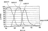
图6是表示该实施方式涉及的透明滤光片2W、黄滤光片2Y、红滤光片2R的分光透射率的一例的图。FIG. 6 is a graph showing an example of the spectral transmittance of the
图7是表示通过该实施方式涉及的摄像元件1的运算得到的外表上的蓝滤光片、绿滤光片、红滤光片的分光透射率的一例的图。FIG. 7 is a graph showing an example of the apparent spectral transmittances of the blue filter, green filter, and red filter obtained by calculation of the
图8是表示以往的摄像元件的分光特性的例子的图。FIG. 8 is a graph showing an example of the spectral characteristics of a conventional imaging element.
图9是表示本发明的第2实施方式涉及的摄像元件9的一例的剖视图。FIG. 9 is a cross-sectional view showing an example of the
图10是表示本发明的第3实施方式涉及的摄像元件11的一例的剖视图。FIG. 10 is a cross-sectional view showing an example of the
图11是用于说明该实施方式涉及的摄像元件11的制造工序的图。FIG. 11 is a diagram for explaining the manufacturing process of the
图12是用于说明该实施方式涉及的摄像元件11的制造工序的图。FIG. 12 is a diagram for explaining the manufacturing process of the
图13是用于说明该实施方式涉及的摄像元件11的制造工序的图。FIG. 13 is a diagram for explaining the manufacturing process of the
图14是用来说明有关该实施方式的摄像元件11的制造工序的图。FIG. 14 is a diagram for explaining the manufacturing process of the
图15是用于说明该实施方式涉及的摄像元件11的制造工序的图。FIG. 15 is a diagram for explaining the manufacturing process of the
图16是表示本发明的第4实施方式涉及的摄像元件17的遮光膜19的配置一例的平面图。FIG. 16 is a plan view showing an example of the arrangement of the
图17是表示本发明的第5实施方式涉及的摄像元件31的滤光片的排列状态一例的主视图。FIG. 17 is a front view showing an example of an arrangement state of filters of the
图18是表示该实施方式涉及的摄像元件31的一例的剖视图。FIG. 18 is a cross-sectional view showing an example of the
图19是表示该实施方式涉及的摄像元件31的另一例的图。FIG. 19 is a diagram showing another example of the
图20是表示该实施方式涉及的补偿滤光片2Blk、透明滤光片2W、黄滤光片2Y、红滤光片2R的分光透射率的一例的图。FIG. 20 is a diagram showing an example of the spectral transmittance of the compensation filter 2Blk, the
图21是表示通过该实施方式涉及的摄像元件31的运算得到的外表上的蓝滤光片、绿滤光片、红滤光片的分光透射率的一例的图。FIG. 21 is a diagram showing an example of the apparent spectral transmittances of the blue filter, green filter, and red filter obtained by calculation of the
图22是表示该实施方式涉及的补偿滤光片的分光特性的图。FIG. 22 is a graph showing the spectral characteristics of the compensation filter according to this embodiment.
图23是表示一般的吸收型的红外线截止滤光片的分光特性的图。FIG. 23 is a graph showing spectral characteristics of a general absorption type infrared cut filter.
图24是表示本发明的第6实施方式涉及的摄像元件39的一例的剖视图。FIG. 24 is a cross-sectional view showing an example of the
图25是表示本发明的第7实施方式涉及的摄像元件41的一例的剖视图。FIG. 25 is a cross-sectional view showing an example of the
图26是表示本发明的第8实施方式涉及的摄像元件47的遮光膜19的配置的第1例的主视图。FIG. 26 is a front view showing a first example of the arrangement of the light-shielding
图27是表示该实施方式涉及的摄像元件47的剖视图。FIG. 27 is a cross-sectional view showing the
图28是表示该实施方式涉及的摄像元件44的遮光膜19的配置的第2例的剖视图。FIG. 28 is a cross-sectional view showing a second example of the arrangement of the light-shielding
图29是表示本发明的第9实施方式涉及的补偿滤光片的分光透射率特性的图。29 is a graph showing spectral transmittance characteristics of a compensation filter according to a ninth embodiment of the present invention.
图30是表示该实施方式涉及的补偿滤光片的分光透射率特性的图。FIG. 30 is a graph showing the spectral transmittance characteristics of the compensation filter according to this embodiment.
图31是表示本发明的第10实施方式涉及的补偿滤光片的分光特性的图。FIG. 31 is a graph showing spectral characteristics of a compensation filter according to a tenth embodiment of the present invention.
图32是表示本发明的第11实施方式涉及的摄像元件的结构的示意图。FIG. 32 is a schematic diagram showing the configuration of an imaging element according to an eleventh embodiment of the present invention.
图33是表示从入射光侧看该实施方式涉及的摄像部110中的滤色片时的排列状态的概念的图。FIG. 33 is a diagram showing a concept of an arrangement state of the color filters in the
图34A是表示该实施方式涉及的摄像部110的截面的一例的图。FIG. 34A is a diagram showing an example of a cross section of the
图34B是表示该实施方式涉及的摄像部110的截面的一例的图。FIG. 34B is a diagram showing an example of a cross section of the
图35是用于说明该实施方式涉及的摄像元件的动作的图。FIG. 35 is a diagram for explaining the operation of the imaging element according to this embodiment.
图36是表示光波长的变化对人眼的刺激值的图。Fig. 36 is a graph showing stimulation values of human eyes by changes in light wavelength.
图37A是用于说明本发明的第12实施方式涉及的摄像部110的制造方法的图。FIG. 37A is a diagram illustrating a method of manufacturing the
图37B是用于说明摄像部110的制造方法的图。FIG. 37B is a diagram for explaining a method of manufacturing the
图37C是用于说明摄像部110的制造方法的图。FIG. 37C is a diagram for explaining a method of manufacturing the
图37D是用于说明摄像部110的制造方法的图。FIG. 37D is a diagram for explaining a method of manufacturing the
图38A是用于说明摄像部110的制造方法的图。FIG. 38A is a diagram for explaining a method of manufacturing the
图38B是用于说明摄像部110的制造方法的图。FIG. 38B is a diagram for explaining a method of manufacturing the
图38C是用于说明摄像部110的制造方法的图。FIG. 38C is a diagram for explaining a method of manufacturing the
图38D是用于说明摄像部110的制造方法的图。FIG. 38D is a diagram for explaining a method of manufacturing the
图38E是用于说明摄像部110的制造方法的图。FIG. 38E is a diagram for explaining a method of manufacturing the
图39是表示该实施方式涉及的摄像元件的另一例的图。FIG. 39 is a diagram showing another example of the imaging element according to this embodiment.
图40是表示该实施方式涉及的摄像元件的另一例的图。FIG. 40 is a diagram showing another example of the imaging element according to this embodiment.
图41是表示本发明的第13实施方式涉及的摄像元件结构的示意图。FIG. 41 is a schematic diagram showing the configuration of an imaging device according to a thirteenth embodiment of the present invention.
图42是从入射光侧看该实施方式涉及的摄像部110T中的滤色片114时的排列状态的概念的图。FIG. 42 is a conceptual view of the arrangement state of the color filters 114 in the
图43A是表示该实施方式涉及的摄像部110T的一例的剖视图。FIG. 43A is a cross-sectional view showing an example of an
图43B是表示该实施方式涉及的摄像部110T的一例的剖视图。FIG. 43B is a cross-sectional view showing an example of an
图44是表示该实施方式涉及的摄像部110T的另一例的图。FIG. 44 is a diagram showing another example of the
图45是表示人的视觉灵敏度、受光元件的灵敏度(SPD灵敏度)、理想的红外线截止滤光片的波长和透射率之间关系的图。FIG. 45 is a graph showing the relationship between human visual sensitivity, sensitivity of a light receiving element (SPD sensitivity), and wavelength and transmittance of an ideal infrared cut filter.
图46是表示反射式的红外线截止滤光片与吸收型的红外线截止滤光片中的光的波长与透射率之间关系的图。46 is a graph showing the relationship between the wavelength of light and the transmittance in a reflective infrared cut filter and an absorptive infrared cut filter.
图47是表示本发明的第1实施例的平坦化层的分光特性的图。Fig. 47 is a graph showing the spectral characteristics of the planarization layer according to the first embodiment of the present invention.
图48是表示该第1实施例涉及的透明滤光片114W、黄滤光片114Y、红滤光片114R、补偿滤光片114Blk的分光特性的图。FIG. 48 is a diagram showing spectral characteristics of the
图49是表示通过该第1实施例涉及的摄像元件的运算得到的外表上的蓝滤光片、绿滤光片、红滤光片的分光特性的图。Fig. 49 is a graph showing the spectral characteristics of the apparent blue filter, green filter, and red filter obtained by computation of the imaging element according to the first embodiment.
图50是表示本发明的第2实施例涉及的透明树脂的分光特性的图。Fig. 50 is a graph showing the spectral characteristics of a transparent resin according to the second embodiment of the present invention.
图51是表示该第2实施例涉及的透明滤光片114W、黄滤光片114Y、红滤光片114R、补偿滤光片114Blk的分光特性的图。FIG. 51 is a diagram showing the spectral characteristics of the
图52是表示通过该第2实施例涉及的摄像元件的运算得到的外表上的蓝滤光片、绿滤光片、红滤光片的分光特性的图。Fig. 52 is a graph showing the spectral characteristics of the apparent blue filter, green filter, and red filter obtained by computation of the imaging element according to the second embodiment.
图53是表示本发明的第14实施方式涉及的滤光片F1~F7的分光特性的一例的图。FIG. 53 is a diagram showing an example of the spectral characteristics of the filters F1 to F7 according to the fourteenth embodiment of the present invention.
图54是用于说明该实施方式涉及的外表上的滤色片的概念的图。FIG. 54 is a diagram for explaining the concept of an external color filter according to this embodiment.
图55是表示本发明的第15实施方式涉及的摄像元件的一例的主视图。FIG. 55 is a front view showing an example of an imaging element according to a fifteenth embodiment of the present invention.
图56是表示该实施方式涉及的滤光片F1~F7的分光特性的一例的图。FIG. 56 is a diagram showing an example of the spectral characteristics of the filters F1 to F7 according to this embodiment.
具体实施方式 Detailed ways
以下,参照附图对本发明的实施方式进行说明。另外,在以下的说明中对于相同的要素赋予相同的标记,并省略其说明。Hereinafter, embodiments of the present invention will be described with reference to the drawings. In addition, in the following description, the same code|symbol is attached|subjected to the same element, and the description is abbreviate|omitted.
<第1实施方式><First Embodiment>
在本实施方式中,说明在CMOS、CCD等受光元件的光入射侧设置滤光层对观测对象的色成分进行观测的摄像元件。In this embodiment, an imaging element that provides a filter layer on the light incident side of a light receiving element such as a CMOS or a CCD, and observes a color component of an observation object will be described.
图4是表示本实施方式涉及的摄像元件的滤光片的排列状态的一例的平面图。在图4中表示从光入射侧观察的滤光片的状态的例子。FIG. 4 is a plan view showing an example of an arrangement state of filters of the imaging element according to the present embodiment. An example of the state of the filter viewed from the light incident side is shown in FIG. 4 .
图5是表示本实施方式涉及的摄像元件的一例的剖视图。在图5中示出了图4的I—I’截面。另外,在图5以受光元件为CMOS的情况为例进行了图示,但在受光元件为CCD的情况下也相同。以下,在摄像元件的其他剖视图中也是同样的结构。FIG. 5 is a cross-sectional view showing an example of an imaging element according to this embodiment. FIG. 5 shows the II' section of FIG. 4 . In addition, in FIG. 5 , the case where the light receiving element is a CMOS is illustrated as an example, but the same applies to the case where the light receiving element is a CCD. Hereinafter, the same structure applies to other cross-sectional views of the imaging device.
摄像元件1具备用于提取入射光中的特定色成分的滤光层2、经由滤光层2观测入射光的受光元件3、和运算部4。The
滤光层2包括透明滤光片2W、黄滤光片2Y、红滤光片2R。通过使黄滤光片2Y为两个像素、使透明滤光片2W和红滤光片2R分别为1个像素的共计4个像素形成色分离的一个单位。即,使黄滤光片2Y的像素数的比例与透明滤光片2W及红滤光片2R的像素数的合计的比例相等。由此,能够按每一个单位执行后述的{(白)—(黄)}及{(黄)—(红)}的运算处理。The
透明滤光片2W、黄滤光片2Y、红滤光片2R以格子状邻接排列,形成面。The
透明滤光片2W优选主要不吸收400nm以上的长波长的光而使其透射。即,透明滤光片2W使合成了蓝成分、绿成分、红成分的光透射。例如,作为透明滤光片2W,优选以折射率n为1.5左右的透明玻璃为基准、波长400nm以上的光的透射率为95%以上的滤光片。这样的透明滤光片2W由酚类、聚乙烯类、丙烯类等树脂形成,但从耐热性等的观点出发,优选由聚乙烯类形成,更希望由丙烯类形成。The
黄滤光片2Y是用来提取入射光中的黄成分(合成了红成分与绿成分的光)的滤光片。该黄滤光片2Y是补色系的滤光片。一般补色系的滤光片的光透射率比蓝、绿、红的三原色系的滤色片高。The
红滤光片2R是用来提取入射光中的红色成分的红的滤色片。一般红的滤色片的透射率比作为三原色系的其他滤色片的蓝的滤光片及绿的滤光片高。The
受光元件3配置在滤光层2的光入射侧的相反侧,具备入射光受光元件3W、黄受光元件3Y、红受光元件3R。此外,受光元件3具有接受经过了滤光层2的光、将接受到的光变换为电信号并求出观测数值(强度值)的功能。另外,受光元件与滤光片的一对一的组合,相当于像素。此外,受光元件3形成在半导体基板5的光入射侧。The
入射光受光元件3W对应于透明滤光片2W,经由透明滤光片2W观测入射光。The incident
黄受光元件3Y对应于黄滤光片2Y,经由黄滤光片2Y观测入射光。The yellow
红受光元件3R对应于红滤光片2R,经由红滤光片2R观测入射光。The red
运算部4具备蓝运算部4B、绿运算部4G、红运算部4R。运算部4具有根据入射光受光元件3W、黄受光元件3Y、红受光元件3R的观测数值Dw、Dy求出蓝的观测数值Db和绿的观测数值Dg的功能。The computing unit 4 includes a
蓝运算部4B从由入射光受光元件3W观测的观测数值Dw中减去由黄受光元件3Y观测的观测数值Dy,求出蓝的观测数值Db(=Dw—Dy)。The
绿运算部4G从由黄受光元件3Y观测的观测数值Dy中减去由红受光元件3R观测的观测数值Dr,求出绿的观测数值Dg(=Dy—Dr)。The
即,如果设对应于透明滤光片2W、黄滤光片2Y、红滤光片2R的色分别为白(W)、黄(Y)、红(R),则以下的(1)式及(2)式的关系式成立。That is, if the colors corresponding to the
蓝(B)=白(W)—黄(Y) ……(1)Blue (B) = white (W) - yellow (Y) ... (1)
绿(G)=黄(Y)—红(R) ……(2)Green (G) = yellow (Y) - red (R) ... (2)
在图5中,表示将黄滤光片2Y与透明滤光片2W横剖、并且将黄受光元件3Y与入射光受光元件3W横剖的剖面。另外,将其他滤光片及其他受光元件横剖的剖面,也是同样的结构。In FIG. 5 , a cross section of the
在半导体基板5的光入射侧形成有受光元件3。The
在形成有受光元件3的半导体基板5的光入射侧的面上,层叠有平坦化层6。由此,能够使滤光层2形成为平坦的设置面。作为平坦化层6的材料,可以使用含有丙烯类或环氧类、聚酰亚胺类、氨酯类、三聚氰胺类、聚酯类、尿素类、苯乙烯类等的树脂的一种或多种的树脂。A
在平坦化层6的光入射侧,形成有对应于受光元件3的滤光层2,此外,在滤光层2的光入射侧,层叠有树脂层(透明平坦化层)7。On the light incident side of the
在树脂层7的光入射侧,具备对应于受光元件3的微透镜8。On the light incident side of the resin layer 7 , a
微透镜8配置在各透明滤光片2W、黄滤光片2Y、红滤光片2R的上方,使其与各透明滤光片2W、黄滤光片2Y、红滤光片2R成对。此外,微透镜8由丙烯树脂等形成,提高向入射光受光元件3W、黄受光元件3Y、红受光元件3R的聚光性。The
另外,在本实施方式中,各滤光层2的膜厚分别为1.4μm,像素间距(透明滤光片2W、黄滤光片2Y、红滤光片2R的间距)为2.6μm。In addition, in this embodiment, the film thickness of each
在上述的平坦化层6中添加有紫外线吸收剂。具体而言,平坦化层6由添加了紫外线吸收剂的热固化型的丙烯树脂形成,膜厚形成为0.3μm。对平坦化层6添加紫外线吸收剂是为了在利用光刻法形成滤光层2时防止从作为基底的半导体基板5的图案曝光光的晕影而形成形状良好的滤光片。另外,这里,通过光刻法对感光性树脂层进行图案曝光及显影等,使感光性树脂残留在规定部位。An ultraviolet absorber is added to the above-mentioned
另外,在本实施方式中形成有平坦化层6,但以将摄像元件进一步减薄为目的,可以省略平坦化层6。In addition, in this embodiment, the
另外,在本实施方式中,透明滤光片2W由碱性可溶型的感光性丙烯树脂(折射率n=1.55)形成。In addition, in the present embodiment, the
此外,黄滤光片2Y及红滤光片2R是利用在透明滤光片2W的形成中使用的透明树脂(感光性丙烯树脂)中,添加规定的有机颜料而分散的着色感光性树脂形成的。例如,作为在黄滤光片2Y的形成中使用的有机颜料,可以举出C.I.Pigment Yellow 150。此外,也可以使用C.I.Pigment Yellow 150与C.I.Pigment Yellow 139的混合类颜料。此外,作为在红滤光片2R的形成中使用的有机颜料,可以举出C.I.Pigment Red 177、C.I.Pigment Red 48:1、和C.I.Pigment Yellow139的混合等。另外,透明滤光片2W也可以由不添加着色物的透明树脂形成。In addition, the
图6是表示关于透明滤光片2W、黄滤光片2Y、红滤光片2R的分光透射率的一例的曲线图。FIG. 6 is a graph showing an example of the spectral transmittance of the
摄像元件1根据各受光元件的观测数值Dw、Dy、Dr进行运算(减法),得到蓝、绿、红的三原色的观测数值Db、Dg、Dr。即,摄像元件1通过进行这样的运算,可以认为在外表上(假想地)具备了蓝滤光片和绿滤光片。The
图7是表示关于通过摄像元件1的运算得到的外表上的蓝滤光片、绿滤光片、红滤光片的分光透射率的一例的曲线图。如果比较图7所示的摄像元件1的外表上的蓝滤光片及绿滤光片的分光透射率与图1所示的以往的蓝及绿的滤色片的分光透射率,则摄像元件1的外表上的蓝滤光片及绿滤光片的透射率具有比以往的蓝及绿的滤光片的透射率高的特征。特别是,外表上的蓝滤光片的透射率比以往的蓝滤光片的透射率高。因此,本实施方式涉及的摄像元件1的蓝的灵敏度高,色平衡好。FIG. 7 is a graph showing an example of the spectral transmittance of the apparent blue filter, green filter, and red filter obtained by calculation of the
进而,比较本实施方式涉及的摄像元件1和以往的摄像元件,在以下进行说明。Furthermore, a comparison between the
首先,对“外表上的滤色片”进行说明。First, the "color filter on the appearance" will be described.
图8是表示以往的摄像元件的分光特性的例子的图。FIG. 8 is a graph showing an example of the spectral characteristics of a conventional imaging element.
以往的摄像元件的分光特性认为与将受光元件的灵敏度(图8(A))、和在受光元件的光入射侧配置的滤光片的透射率(图8(B))相乘的积的值等价,如图8(C)那样表示。The spectral characteristic of a conventional imaging element is considered to be the product of the sensitivity of the light-receiving element (Fig. 8(A)) and the transmittance of the filter placed on the light incident side of the light-receiving element (Fig. The values are equivalent, as shown in Fig. 8(C).
如图8(B)所示,以往的摄像元件中的蓝的滤色片的透射率比红及绿的滤色片的透射率低。此外,如图8(A)所示,蓝的波长区中的受光元件的灵敏度比红及绿的波长区中的灵敏度低。因此,如果在以往的摄像元件中求灵敏度比,则(蓝/绿)比(红/绿)小。因此,色再现性变低。As shown in FIG. 8(B) , the transmittance of the blue color filter in the conventional imaging element is lower than the transmittance of the red and green color filters. In addition, as shown in FIG. 8(A), the sensitivity of the light receiving element in the blue wavelength range is lower than that in the red and green wavelength ranges. Therefore, when the sensitivity ratio is found in the conventional imaging element, (blue/green) is smaller than (red/green). Therefore, color reproducibility becomes low.
相对于此,本实施方式中的摄像元件1具备透明滤光片2W、黄滤光片2Y、红滤光片2R,来代替作为三原色的红、绿、蓝的滤色片。因此,本实施方式中的摄像元件1的分光特性认为与将受光元件的灵敏度、和在受光元件的光入射侧配设的透明滤光片2W、黄滤光片2Y、红滤光片2R的透射率分别相乘的积的值等价。透明滤光片2W、黄滤光片2Y、红滤光片2R的透射率比蓝的滤色片及绿的滤色片高。因而,由入射光受光元件3W、黄受光元件3Y、红受光元件3R经透明滤光片2W、黄滤光片2Y、红滤光片2R观测到入射光的情况下,根据其观测数值Dw、Dy、Dr计算出的观测数值Db、Dg可以说是通过高的透射率得到的观测结果。特别是,对于蓝的观测数值Db,能够增大(蓝/绿)的灵敏度比,能够提高色再现性。On the other hand, the
进而,在本实施方式中,能够通过1次的减法处理求出蓝的观测数值Db及绿的观测数值Dg。因而,与使用以往的补色系的滤色片的摄像元件相比,能够使运算简单化,能够表现接近于原色的鲜艳的色。Furthermore, in the present embodiment, the blue observed value Db and the green observed value Dg can be obtained by one subtraction process. Therefore, compared with an imaging element using a conventional color filter of a complementary color system, calculation can be simplified, and vivid colors close to primary colors can be expressed.
接着,对“暗电流带来的噪声”进行说明。Next, "noise due to dark current" will be described.
如图8(C)所示,受光元件即使在光没有入射的情况下也会产生微弱的电流。这样的尽管没有光入射但从受光元件流出的电流称作“暗电流(dark current)”,成为噪声的原因。以往的蓝、绿、红的三原色的滤色片在分光特性上是使规定的波长区的光透射的滤色片,还存在遮蔽光的波长区。As shown in FIG. 8(C), the light receiving element generates a weak current even when no light is incident on it. Such a current flowing from the light receiving element despite no light incident is called "dark current" and causes noise. Conventional color filters of the three primary colors of blue, green, and red transmit light in a predetermined wavelength region in terms of spectral characteristics, and there are also wavelength regions that block light.
但是,在受光元件中,在遮蔽光的波长区中也产生暗电流。因此,在以往的摄像元件的观测结果中,除了使光透射的波长区中的光的观测结果以外,还包含暗电流的噪声,有时该噪声会使色再现性下降。However, in the light receiving element, dark current also occurs in the wavelength range where light is blocked. Therefore, the observation result of the conventional imaging device includes, in addition to the observation result of light in the wavelength region through which light is transmitted, noise of dark current, which may degrade color reproducibility.
相对于此,本实施方式涉及的摄像元件1如上所述地将入射光受光元件3W的观测数值Dw与黄受光元件3Y的观测数值Dy进行减法处理,将黄受光元件3Y的观测数值Dy与红受光元件3R的观测数值Dr进行减法处理,所以暗电流的值相抵消。因此,能够从观测结果中除去噪声,能够提高色再现性。On the other hand, in the
接着,对“分光的浮动”进行说明。Next, the "floating of the spectrum" will be described.
如图8(B)所示,在以往的蓝、绿、红的滤色片的分光透射率中,蓝和红的滤色片的分光曲线的下降边的透射率低几个百分点,绿的滤色片的分光曲线的下降边的透射率高10%左右。这样,将下降边高称作分光的浮动大。As shown in FIG. 8(B), among the spectral transmittances of conventional blue, green, and red color filters, the transmittances of the descending sides of the spectral curves of the blue and red color filters are several percentage points lower than those of the green ones. The transmittance of the falling edge of the spectral curve of the color filter is about 10% higher. In this way, the trailing edge height is referred to as the large fluctuation of the spectrum.
在以往的摄像元件中,绿的滤色片的分光曲线的下降边存在于蓝及红的波长区中。此外,绿的下降边的分光的浮动较大。因此,在绿的观测结果中,蓝及红混色,存在绿的再现性下降的问题。In a conventional imaging device, the falling edge of the spectral curve of the green color filter exists in the blue and red wavelength regions. In addition, the spectral fluctuation of the green descending side is large. Therefore, in the observation result of green, blue and red are mixed, and there is a problem that the reproducibility of green is lowered.
相对于此,在本实施方式涉及的摄像元件1中,将黄受光元件3Y的观测数值Dy与红受光元件3R的观测数值Dr进行减法处理,求出绿的观测数值Dg。因此,能够减小分光的浮动,能够提高色再现性。On the other hand, in the
接着,对“紫外线吸收剂及红外线吸收剂”进行说明。Next, the "ultraviolet absorber and infrared absorber" will be described.
CMOS及CCD等的受光元件对人感觉不到的紫外线区有一些灵敏度。因此,本实施方式涉及的滤光层2优选吸收400nm以下的光而不使其透射,并且不吸收400nm以上的波长的光而使其透射。这里,优选在透明滤光片2W中添加紫外线吸收剂或在树脂的固化中使用的光引发剂及固化剂,使透明滤光片2W具有紫外线吸收功能。作为紫外线吸收剂,可以使用例如苯并三唑类化合物或二苯甲酮类化合物、水杨酸类化合物、香豆素类化合物。此外,在紫外线吸收剂中,也可以添加例如受阻胺类化合物等光稳定剂或淬灭剂等使用。进而,在用于透明滤光片2W形成的树脂的聚合物或单体、或者固化剂中悬置具有紫外线吸收功能的功能基、或使其具有取入到聚合物中那样的基而进行聚合。例如,也可以将醌类或蒽导入到聚合物中,也可以将紫外线吸收性的基添加到单体中。另外,所谓的悬置,是指以反应型吸收剂等的形式组合到树脂分子链中。Light-receiving elements such as CMOS and CCD have some sensitivity to ultraviolet rays that humans cannot feel. Therefore, the
再者,优选将红外线吸收性化合物或红外线吸收剂添加到构成透明滤光片2W的树脂中。例如通过悬置方式添加到构成透明滤光片2W的树脂中。Furthermore, it is preferable to add an infrared absorbing compound or an infrared absorbing agent to the resin constituting the
再者,根据本实施方式,滤光层2通过使黄滤光片2Y为两个像素、使透明滤光片2W和红滤光片2R分别为1个像素的共计4个像素形成色分离的一个单位。因此,在取得蓝及绿的观测数值时,不需要重复使用黄色的数据值。即,在运算部4中,能够在一个单位内单独地执行{(白)—(黄)}和{(黄)—(红)}的运算处理。由此,能够实现运算处理的高速化。Furthermore, according to the present embodiment, the
如以上说明,本实施方式涉及的摄像元件1通过1次减法处理就能够在外表上看作是具备了高透射性的蓝滤光片及绿滤光片的摄像元件,特别是与以往的摄像元件相比提高了蓝的观测精度。As described above, the
<第2实施方式><Second embodiment>
在本实施方式中,对第1实施方式涉及的摄像元件1的变形例进行说明。另外,本实施方式涉及的摄像元件9是,在第1实施方式涉及的摄像元件1中将透明滤光片2W与树脂层7一体构成。另外,对于与已说明的部分相同的部分赋予相同的标记,并省略说明。In this embodiment, a modified example of the
图9是表示本实施方式涉及的摄像元件的一例的剖视图。图9是对应于图4的I—I’截面的图。此外,透明滤光片10W相当于第1实施方式的透明滤光片2W及树脂层7。FIG. 9 is a cross-sectional view showing an example of an imaging element according to this embodiment. Fig. 9 is a view corresponding to the II' section of Fig. 4 . In addition, the
本实施方式涉及的摄像元件9在第1实施方式涉及的透明滤光片2W的位置配置了透明滤光片10W的一部分。In the
透明滤光片10W的其他部分覆盖黄滤光片2Y及红滤光片2R的光入射侧的面。即,透明滤光片10W是将第1实施方式涉及的透明滤光片2W与树脂层7作为一体的结构,还具有作为透明平坦化层的作用。The other part of the
与第1实施方式同样,摄像元件9根据各受光元件3的观测数值Dw、Dy、Dr进行运算(减法),得到蓝及绿的观测数值Db、Dg。即,摄像元件9根据各受光元件3的观测数值进行运算(减法),可以认为在外表上(假想地)具备了蓝滤光片及绿滤光片和红滤光片。Similar to the first embodiment, the
关于通过摄像元件9的运算得到的外表上的蓝滤光片及绿滤光片、和红滤光片的波长400nm~800nm的分光透射率的一例,示出了与图7同样的曲线。An example of the spectral transmittance of the apparent blue filter, green filter, and red filter at a wavelength of 400 nm to 800 nm obtained by the calculation of the
如以上说明,在本实施方式中,在形成黄滤光片2Y和红滤光片2R后,形成透明滤光片10W以覆盖各滤光片。此时,透明滤光片10W与透明平坦化层以一体的结构形成。As described above, in this embodiment, after the
即,通过同时进行透明滤光片10W与透明平坦化层的形成工序,不需要单独地设置透明滤光片的图案形成工序,能够使摄像元件9的制造过程简单化。That is, by simultaneously performing the steps of forming the
详细地讲,在第1实施方式中形成了透明滤光片2W的部分配置作为透明平坦化层的透明滤光片10W的一部分,透明滤光片10W实现作为透明平坦化层的作用。因此,在例如光刻法等中能够省略单独形成透明滤光片的工序。即,能够通过形成两色(黄、红)的滤光片的劳动就形成3色的滤光片,能够将滤光片形成工序减少1个色的量。Specifically, in the first embodiment, the portion where the
<第3实施方式><third embodiment>
在本实施方式中,对第1及第2实施方式涉及的摄像元件的变形例进行说明。In this embodiment, modified examples of the imaging elements according to the first and second embodiments will be described.
图10是表示有关本实施方式的摄像元件的一例的剖视图。FIG. 10 is a cross-sectional view showing an example of the imaging element according to this embodiment.
有关本实施方式的摄像元件11具备将第2实施方式涉及的摄像元件9的微透镜8与透明滤光片10W做成一体的构造的透明滤光片12W。透明滤光片12W还具有提高向入射光受光元件3W、黄受光元件3Y、红受光元件3R的聚光性的功能。The
以下,利用图11~图15说明该摄像元件11的制造工序。Hereinafter, the manufacturing process of this
首先,在形成有入射光受光元件3W、黄受光元件3Y、红受光元件3R的半导体基板5上,形成由透明树脂构成的平坦化层6(图11)。具体而言,在二维地配设有受光元件的半导体基板5上,以2000rpm的转速旋转涂布以丙烯树脂为主成分的涂布液。接着,通过进行200℃的热处理进行硬膜化,形成膜厚为0.2μm的平坦化层6。在丙烯树脂的涂布液中,使用添加了固形比为约3%的香豆素类紫外线吸收剂的涂布液。First, a
另外,在由着色感光性树脂构成的滤色片的形成中,在对色感光性树脂的图案曝光中使用紫外线。在图案曝光时有时会产生晕影。所以,为了防止晕影,优选在平坦化层6中添加紫外线吸收剂。另外,为了使摄像元件11变薄,也可以省略平坦化层6。In addition, in forming a color filter made of colored photosensitive resin, ultraviolet rays are used for pattern exposure of the color photosensitive resin. Vignetting sometimes occurs when the pattern is exposed. Therefore, in order to prevent vignetting, it is preferable to add an ultraviolet absorber to the
接着,利用光刻法形成黄滤光片2Y及红滤光片2R(图12)。Next, the
详细地讲,使用在能够曝光、显影的感光性丙烯树脂中混合颜色材料的两种彩色光阻剂(黄、红),分别形成约1μm膜厚的黄滤光片2Y和红滤光片2R。另外,黄滤光片2Y的颜色材料可以使用有机颜料C.I.Pigment Yellow 150。黄滤光片2Y的颜色材料(有机颜料)的固形比是约33%。此外,红滤光片2R的颜色材料可以使用C.I.Pigment Red 177、C.I.Pigment Red 48:1和C.I.Pigment Yellow 139的混合颜料。红滤光片2R的颜色材料(有机颜料)的固形比为约48%。Specifically, two color photoresists (yellow and red) mixed with color materials in a photosensitive acrylic resin capable of exposure and development are used to form a
接着,在半导体基板5上旋转涂布透明树脂层,使其覆盖黄滤光片2Y及红滤光片2R。接着,将透明树脂层在180℃下进行3分钟热固化,形成包含透明滤光片12W的平坦化层12。平坦化层12使用与平坦化层6大致相同的材料,利用为了厚膜用而提高了固形比的热固化型的丙烯树脂的涂布液形成。另外,在丙烯树脂中含有2%的香豆素类的紫外线吸收剂。此外,平坦化层12为约2μm膜厚。Next, a transparent resin layer is spin-coated on the
并且,在平坦化层12上形成能够曝光、显影的感光性酚醛树脂层13(图13)。另外,感光性酚醛树脂层13是具有“热回流性”的树脂。所谓的热回流性是指,由热处理熔融而在表面张力作用下变圆为透镜状的性质。In addition, a photosensitive
接着,对感光性酚醛树脂层13进行图案曝光、显影、硬膜处理等,形成规定图案的感光性酚醛树脂。Next, pattern exposure, development, hard coating, etc. are performed on the photosensitive
接着,进行200℃的加热处理,使规定图案的感光性酚醛树脂层13流动化。由此,形成约0.6μm厚度的半球状的透镜母模13a(图14)。Next, heat treatment at 200° C. is performed to fluidize the photosensitive
接着,通过以透镜母模13a为掩模进行各向异性的干式蚀刻,将透镜母模13a的形状转印到平坦化层12上,形成微透镜(图15)。即,通过蚀刻使透镜母模13a消失,但透镜母模13a成为对透明滤光片12W的掩模,将透镜母模13a的半球状的形状转印到透明滤光片12W上。由此,同时形成微透镜8和透明滤光片12W。另外,干式蚀刻量(蚀刻深度)为约1μm。此外,黄滤光片2Y与红滤光片2R成为到达其表面的执行蚀刻深度为1.2μm的膜厚。Next, anisotropic dry etching is performed using the
如以上说明,能够得到透明滤光片12W的一部分作为微透镜发挥功能的摄像元件11。此外,由于透明滤光片12W与微透镜一体化,所以能够使摄像元件11变薄。As described above, it is possible to obtain the
另外,在本实施方式中,将具有透明平坦化膜的作用的透明滤光片12W做成微透镜的形状,但也可以是不形成微透镜而是保持具有平坦化层的作用的透明滤光片12W的状态。在此情况下,在图13的第3工序中形成透明滤光片12W后,不进行感光性酚醛树脂层13的形成以后的工序。In addition, in this embodiment, the
此外,如上所述,在平坦化层6中,为了防止在对色感光性树脂的图案曝光时产生的晕影,优选添加紫外线吸收剂。In addition, as described above, it is preferable to add an ultraviolet absorber to the
此外,在透明滤光片12W中,为了防止基于受光元件在紫外线区域中具有灵敏度的、紫外线带来的噪声的发生,优选添加紫外线吸收剂。In addition, it is preferable to add an ultraviolet absorber to the
作为紫外线吸收剂,可以举出由氧化铈或氧化钛等金属氧化物构成的微粒子。但是,如上所述,在透明滤光片12W上转印透镜形状、透明滤光片12W成为转印型的微透镜的情况下,在紫外线吸收剂是由金属氧化物层构成的情况下,在转印透镜的树脂中无机材料成为光学的异物。因此,在光被遮蔽的情况下,在由摄像元件11得到的图像中产生黑的部分。因而,优选使用染料类的紫外线吸收剂。例如,作为紫外线吸收剂,可以使用苯并三唑类或二苯甲酮类、三嗪类、水杨酸酯类、香豆素类、呫吨类、甲氧肉桂酸类化合物等。Examples of the ultraviolet absorber include fine particles made of metal oxides such as cerium oxide and titanium oxide. However, as described above, when the lens shape is transferred onto the
另外,在第1~第3实施方式中,对于黄色也可以作为除了透明部以外的其他色的底色使用。即,除了透明部以外,黄色也可以共通地被包含在红色部中。此情况下,例如在利用黄色的树脂形成黄滤光片2Y的同时,在红滤光片的形成位置也形成黄滤光片2Y,然后在红滤光片的形成位置形成红滤光片2R。In addition, in the first to third embodiments, yellow may be used as a base color of other colors other than the transparent part. That is, in addition to the transparent part, yellow may be commonly included in the red part. In this case, for example, while the
<第4实施方式><Fourth embodiment>
在本实施方式中,对设置了抑制入射到受光元件中的入射光以外的光引起的反射及扩散、绕入的遮光膜(反射抑制滤光片)的摄像元件进行说明。In this embodiment, an imaging element provided with a light-shielding film (reflection suppression filter) that suppresses reflection, diffusion, and wrap-around of light other than incident light entering the light receiving element will be described.
图16是表示本实施方式涉及的摄像元件的遮光膜的配置的一例的平面图。图16所示的摄像元件17在受光元件的光入射侧的设有滤光层2的有效像素部18的外周部,具备抑制光的反射及透射的遮光膜19。另外,摄像元件17具有用于进行与外部的电连接的由铝等构成的电极部20。在电极部20不形成遮光膜19。16 is a plan view showing an example of the arrangement of light-shielding films of the imaging element according to this embodiment. The
作为遮光膜19的颜色材料,可以使用例如分散混合了有机颜料(C.I.Pigment Violet 23及C.I.Pigment Red 177、C.I.Pigment Red 48:1、C.I.Pigment Yellow 139的混合)的树脂液。如果涂布该颜色材料并硬膜化,形成遮光膜19。但是,颜色材料并不限于此,也可以使用其他颜料。此外,也可以是单层,也可以层叠不同的色。As the color material of the light-shielding
如果将这样的遮光膜19配设在摄像元件17的有效像素部18的外周部,则能够防止摄像元件17的观测结果受到噪声的影响。结果,能够提高像质。If such a light-shielding
如果进行补充,则在以往的摄像元件中,有时入射到受光元件以外部分的光在摄像元件内散射而成为杂光。该杂光如果入射到受光元件中,则成为噪声。此外,如果不需要的光入射到受光元件的周边区域,则成为噪声的原因。In addition, in conventional imaging elements, light incident on parts other than the light receiving element may be scattered inside the imaging element to become stray light. When this stray light enters the light receiving element, it becomes noise. In addition, when unnecessary light enters the peripheral area of the light receiving element, it becomes a cause of noise.
相对于此,本实施方式涉及的摄像元件17在受光元件的有效开口部周边、以及半导体基板5的一部分(例如半导体基板5的外周),配置有在可见光波长区具有抑制透射特性的遮光膜19。因此,利用遮光膜19吸收入射到受光元件以外部分的光。由此,能够防止杂光等不需要的光入射到受光元件。即,能够降低噪声,能够提高通过摄像元件17得到的像质。On the other hand, in the
此外,在本实施方式中,优选使遮光膜19除了具有将可见光线截止的功能,还具有将红外线截止的功能。具体而言,通过使用将炭黑等黑色颜料以固形比40%混合的树脂液,将遮光膜19形成为0.8μm的膜厚,来实现紫外线截止功能。In addition, in the present embodiment, it is preferable that the light-shielding
再者,也可以在使用了炭黑等黑色颜料的遮光膜19上层叠吸收红外线及紫外线的吸收膜。由此,能够防止入射到不是受光元件的部分中的红外线及紫外线散射而成为杂光,发生噪声的情况。另外,作为该吸收红外线及紫外线的吸收膜,如果使用在微透镜8的形成中使用的透明树脂中添加了红外线吸收剂及紫外线吸收剂的材料,则能够减少材料费用。Furthermore, an absorbing film that absorbs infrared rays and ultraviolet rays may be laminated on the light-shielding
另外,在本实施方式中,以在第1实施方式涉及的摄像元件1中具备遮光膜19和吸收膜的情况为例进行了说明,但也可以在其他实施方式涉及的摄像元件中具备遮光膜19和吸收膜。此外,也可以在摄像元件中仅具备遮光膜19。此外,也可以在遮光膜19中添加紫外线吸收剂或红外线吸收剂。In addition, in this embodiment, the case where the light-shielding
<第5实施方式><Fifth Embodiment>
本实施方式说明在第1实施方式涉及的摄像元件1中追加了补偿滤光片2Blk的摄像元件31。In this embodiment, an
图17是表示本实施方式涉及的摄像元件31中的滤光片排列状态的一例的主视图。图18是表示该实施方式涉及的摄像元件31的一例的剖视图。在图18中表示图17的III—III’截面。另外,在图18中,以受光元件为CMOS的情况为例进行了图示,但在受光元件为CCD的情况下也同样。以下,在摄像元件的其他剖视图中也是同样的结构。FIG. 17 is a front view showing an example of an arrangement state of filters in the
本实施方式涉及的摄像元件31具备用于提取入射光中的特定色成分的滤光层2、经由滤光层2观测入射光的受光元件3、和运算部4。The
滤光层2除了透明滤光片2W、黄滤光片2Y、红滤光片2R以外,还包括补偿滤光片2Blk。利用一个个地组合了透明滤光片2W、黄滤光片2Y、红滤光片2R、补偿滤光片2Blk的单位,形成色分离的一个单位。透明滤光片2W、黄滤光片2Y、红滤光片2R、补偿滤光片2Blk以格子状邻接排列。另外,各滤光片的膜厚分别为1.4μm,像素间距(透明滤光片2W、黄滤光片2Y、红滤光片2R、补偿滤光片2Blk的间距)为2.6μm。In addition to the
补偿滤光片2Blk在可见光波长区具有抑制透射特性(低透射特性),是在比可见光波长区长的波长侧具有透射特性的滤光片。即,补偿滤光片2Blk具有红外区域的透射率比可见光波长区的透射率高的特性。此外,补偿滤光片2Blk目视时较黑。The compensation filter 2Blk has transmission suppression characteristics (low transmission characteristics) in the visible light wavelength region, and is a filter having transmission characteristics on the longer wavelength side than the visible light wavelength region. That is, the compensation filter 2Blk has a characteristic that the transmittance in the infrared region is higher than that in the visible light wavelength region. In addition, the compensation filter 2Blk is dark when viewed visually.
在本实施方式中,补偿滤光片2Blk是将紫(V)和红(R)光学重叠而形成的。另外,作为光学重叠的具体实现方法,既可以用混合了紫的颜色材料和红的颜色材料的颜色材料来形成一片滤光片,也可以将紫的滤光片与红的滤光片层叠。In this embodiment, the compensation filter 2Blk is formed by optically overlapping violet (V) and red (R). In addition, as a specific realization method of optical superimposition, one filter may be formed by mixing a purple color material and a red color material, or a purple filter and a red filter may be laminated.
受光元件3配置在滤光层2的光入射侧的相反侧,除了入射光受光元件3W、黄受光元件3Y、红受光元件3R以外,还具备补偿受光元件3Blk。这些受光元件3形成并配设在半导体基板5上。The
补偿受光元件3Blk对应于补偿滤光片2Blk,经由补偿滤光片2Blk观测入射光。The compensation light receiving element 3Blk corresponds to the compensation filter 2Blk, and observes incident light through the compensation filter 2Blk.
运算部4具备蓝运算部4B、绿运算部4G、红运算部4R。运算部4具有根据入射光受光元件3W、黄受光元件3Y、红受光元件3R、补偿受光元件3Blk的观测数值Dw、Dy、Dr、Dblk,求出蓝的观测数值Db、绿的观测数值Dg和被补偿的红的观测数值HDr的功能。The computing unit 4 includes a
红运算部4R从由红受光元件3R观测到的观测数值Dr中减去由补偿受光元件3Blk观测到的观测数值Dblk,求出被补偿的红的观测数值HDr(=Dr—Dblk)。The
在图18中,表示将红滤光片2R与补偿滤光片2Blk横剖、并且将红受光元件3R与补偿受光元件3Blk横剖的截面。对于将其他滤光片及其他受光元件横剖的截面,也是同样的结构。FIG. 18 shows a cross section of the
另外,在图18中,表示了将红的颜料和紫的颜料混合到透明树脂中的单层的补偿滤光片2Blk。但是,补偿滤光片2Blk并不限于图18所示的构造,只要是通过光学重叠实现就可以。这里所谓的光学重叠,如图18所示,既可以通过混合了不同的多个色的颜色材料(颜料、色素)的单层的着色树脂来实现,也可以通过两色以上的不同色的滤色片的层叠构造来实现。例如,如图19所示,也可以层叠紫的滤光片2V和红滤光片2R来形成补偿滤光片2Blk。此外,为了色及透射率调节,也可以使用两色以上的颜色材料。In addition, in FIG. 18 , a single-layer compensation filter 2Blk in which a red pigment and a purple pigment are mixed into a transparent resin is shown. However, the compensating filter 2Blk is not limited to the structure shown in FIG. 18, as long as it is realized by optical overlapping. The so-called optical overlapping here, as shown in Figure 18, can be realized by a single-layer colored resin mixed with different multi-colored color materials (pigments, pigments), or can be realized by two or more different-colored filters. The layered structure of color chips is realized. For example, as shown in FIG. 19 , a compensation filter 2Blk may be formed by laminating a
在将两色以上的滤色片光学重叠的情况下,补偿滤光片2Blk的透射率是所重叠的各滤色片的透射率之积。因而,通过用光学重叠形成补偿滤光片2Blk,能够制作在可见光波长区具有抑制透射特性、在比可见光波长区更长的长波长侧具有透射特性的补偿滤光片2Blk。When color filters of two or more colors are optically overlapped, the transmittance of the compensation filter 2Blk is the product of the transmittances of the overlapped color filters. Therefore, by forming the compensating filter 2Blk by optical superimposition, it is possible to fabricate the compensating filter 2Blk having suppressed transmission characteristics in the visible wavelength region and transmissive characteristics on the long wavelength side longer than the visible wavelength region.
作为在补偿滤光片2Blk的形成中使用的有机颜料,可以使用例如C.I.Pigment Violet 23和用于红滤光片2R的有机颜料(例如C.I.Pigment Red 177、C.I.Pigment Red 48:1与C.I.Pigment Yellow 139的混合)的混合。As organic pigments used in the formation of the compensation filter 2Blk, for example C.I.Pigment Violet 23 and organic pigments for the
关于这样形成的补偿滤光片2Blk与透明滤光片2W、黄滤光片2Y、红滤光片2R的分光透射率的一例,如图20所示。An example of the spectral transmittance of the compensating filter 2Blk formed in this way, the
如以上说明,摄像元件31根据各受光元件的观测数值Dw、Dy、Dr、Dblk进行运算(减法),得到蓝、绿、被补偿的红的三原色的观测数值Db、Dg、HDr。换言之,摄像元件31通过进行运算处理,在外表上(假想地)可以认为是具备了蓝滤光片、绿滤光片、红滤光片。As described above, the
图21是表示关于通过摄像元件31的运算得到的外表上的蓝滤光片、绿滤光片、红滤光片的分光透射率的一例的曲线图。如果比较图21所示的摄像元件31的外表上的蓝滤光片、绿滤光片、红滤光片的分光透射率与图1所示的以往的蓝、绿、红滤光片的分光透射率,则具有摄像元件31的外表上的蓝滤光片、绿滤光片、红滤光片的透射率比以往的蓝及绿的滤色片的透射率高的特征。特别是,外表上的蓝滤光片的透射率在蓝的波长区中比以往的蓝滤色片的透射率高。因此,本实施方式涉及的摄像元件31中,蓝的灵敏度高,改善了色平衡。FIG. 21 is a graph showing an example of the spectral transmittance of the apparent blue filter, green filter, and red filter obtained by the calculation of the
此外,由摄像元件31得到的蓝的观测数值Db、绿的观测数值Dg、被补偿的红的观测数值HDr是分别减去红外区域中的观测数值来计算的。因此,外表上的蓝滤光片、绿滤光片、红滤光片中的分光透射率的曲线,成为在以往的蓝、绿、红的滤色片的分光透射率的曲线中抑制(截止)了红外区域的状态。因而,在本实施方式涉及的摄像元件31中,能够省略红外线截止滤光片,能够变薄。此外,由于能够防止在配设了吸收型的红外线截止滤光片时发生的红的灵敏度降低的情况,所以与以往的摄像元件相比,能够使红的色再现性良好。In addition, the blue observed value Db, the green observed value Dg, and the compensated red observed value HDr obtained by the
另外,关于“外表上的滤色片”、“暗电流带来的噪声”、“分光的浮动”、“紫外线吸收剂及红外线吸收剂”,适用与第1实施方式同样的讨论。In addition, the same discussion as that of the first embodiment applies to "color filter on appearance", "noise due to dark current", "spectral fluctuation", "ultraviolet absorber and infrared absorber".
以下,对“补偿滤光片2Blk的分光特性”进行补充。Hereinafter, the "spectral characteristics of compensation filter 2Blk" will be supplemented.
图22是表示利用将紫的颜料(例如C.I.Pigment Violet 23)和红滤光片2R的颜料混合分散的膜厚1.4μm的丙烯树脂膜而形成的补偿滤光片2Blk的分光特性的曲线图。22 is a graph showing the spectral characteristics of the compensation filter 2Blk formed by mixing and dispersing a violet pigment (for example, C.I. Pigment Violet 23) and a
补偿滤光片2Blk的透射率在比可见光波长区更长的长波长侧成为与图20的红滤光片2R的透射率大致相同的水平(相同或近似)。The transmittance of the compensation filter 2Blk is substantially the same level (same or similar) as the transmittance of the
通过从由红受光元件3R观测到的观测数值Dr中减去由补偿受光元件3Blk观测到的观测数值Dblk,能够将红外区域的观测结果从由红受光元件3R观测到的观测数值Dr中删除。换言之,补偿滤光片2Blk发挥对于红的观测数值的红外线截止滤光片的作用。By subtracting the observed value Dblk observed by the compensation light receiving element 3Blk from the observed value Dr observed by the red
图22所示的补偿滤光片2Blk与图23所示的一般的吸收型红外线截止滤光片不同,约600nm~650nm附近的透射率(作为红外线截止滤光片的实际的透射率)较低。因此,能够进一步提高运算(减法)后得到的红的色表现性。The compensation filter 2Blk shown in FIG. 22 is different from the general absorbing infrared cut filter shown in FIG. 23 in that the transmittance around 600 nm to 650 nm (actual transmittance as an infrared cut filter) is low. . Therefore, it is possible to further improve the color expression of red obtained after the calculation (subtraction).
在本实施方式中,补偿滤光片2Blk的透射率在约400nm~550nm光的波长区及750nm以上的波长区中,与图1所示的红滤色片的透射率具有5%以内的差。由此,能够得到不受红外线及其他色的影响的、被补偿的红的观测数值HDr,提高了红的色再现性。具体而言,补偿滤光片2Blk的透射率如图22所示,在约400nm~630nm维持较低值,然后在630nm~750nm之间急剧地上升,如果超过750nm则维持较高值。In this embodiment, the transmittance of the compensating filter 2B1k is within 5% of the transmittance of the red filter shown in FIG. . As a result, it is possible to obtain a compensated observed value HDr of red that is not affected by infrared rays and other colors, thereby improving the color reproducibility of red. Specifically, as shown in FIG. 22 , the transmittance of the compensation filter 2Blk maintains a low value at about 400nm to 630nm, then rises sharply between 630nm and 750nm, and maintains a high value beyond 750nm.
另外,在一般的吸收型红外线截止滤光片中,透射率成为一半(50%)的波长为约630nm附近。在一般的无机多层膜的红外线截止滤光片中,透射率成为一半的波长为约750nm。在由紫与红的光学重叠形成的补偿滤光片2Blk中,透射率成为一半的波长为约650nm~660nm之间。在通过青与红的光学重叠形成的补偿滤光片2Blk中,透射率成为一半的波长为约740nm~750nm。In addition, in a general absorption type infrared cut filter, the wavelength at which the transmittance becomes half (50%) is around 630 nm. In a general infrared cut filter of an inorganic multilayer film, the wavelength at which the transmittance becomes half is about 750 nm. In the compensation filter 2Blk formed by the optical superposition of violet and red, the wavelength at which the transmittance becomes half is between approximately 650 nm and 660 nm. In the compensation filter 2Blk formed by the optical superposition of cyan and red, the wavelength at which the transmittance becomes half is about 740 nm to 750 nm.
根据以上的观点,从提高红的观测数值的精度的观点来看,优选在补偿滤光片2Blk中,使透射值成为一半的点P的波长被包含在630nm~750nm之间的波长区中。此外,优选在透明滤光片2W中添加紫外线吸收剂。From the above point of view, it is preferable that the wavelength of point P at which the transmission value is half is included in the wavelength region between 630nm and 750nm in the compensation filter 2Blk from the viewpoint of improving the accuracy of the observed value of red. In addition, it is preferable to add an ultraviolet absorber to the
在本实施方式涉及的摄像元件31中,通过红的观测值Dr与补偿用的观测数值Dblk之差求,出补偿后的红的观测数值HDr。因而,通过使补偿滤光片2Blk成为图22那样,能够防止补偿后的红的观测数值HDr受到来自红外线及其他色光的影响。此外,能够得到红的灵敏度高、红的色再现性良好的摄像元件31。In the
另外,在本实施方式中,补偿滤光片2Blk如上所述,既可以由例如紫与红的两色的光学重叠构成,也可以由青与红的两色的光学重叠构成。通过组合这样的两色来形成补偿滤光片2Blk,能够通过颜色材料的比例来调节补偿滤光片2Blk的光透射率成为一半的波长位置,还能够对补偿后的红的观测数值HDr进行色调节。In addition, in the present embodiment, as described above, the compensation filter 2Blk may be constituted by, for example, an optical superposition of two colors of purple and red, or may be constituted by an optical superposition of two colors of cyan and red. By combining such two colors to form the compensation filter 2Blk, the wavelength position at which the light transmittance of the compensation filter 2Blk becomes half can be adjusted by the ratio of the color materials, and the observed value HDr of red after compensation can be adjusted. adjust.
此外,补偿滤光片2Blk的可见光波长区中的色调节(例如灰度的调节)、或者700nm或700nm以上的近红外透射分光中的补偿滤光片2Blk的透射率曲线的上升、或透射率成为一半的波长位置的调节,也可以添加其他颜色材料或其他色的有机颜料、例如紫、蓝、绿等的有机颜料来调节。In addition, the color adjustment in the visible light wavelength region of the compensation filter 2Blk (for example, the adjustment of the gradation), or the rise of the transmittance curve of the compensation filter 2Blk in the near-infrared transmission spectrum at or above 700nm, or the transmittance The adjustment of the half-wavelength position can also be adjusted by adding other color materials or organic pigments of other colors, such as organic pigments such as purple, blue, and green.
此外,在本实施方式涉及的摄像元件31中,能够将不是人的可视区域的红外区域的光的观测结果删除,能够得到接近于人的视觉的摄影结果。In addition, in the
此外,在本实施方式涉及的摄像元件31中,与使用具有图23所示的透射特性的一般吸收型的红外线截止滤光片的情况不同,能够缓和从550nm到560nm的波长区的光的吸收。因此,能够提高红的色表现性。In addition, in the
即,在本实施方式涉及的摄像元件31中,能够看作是具备了高透射的蓝、绿、红滤光片的摄像元件,特别是与以往的摄像元件相比,能够提高蓝及红的观测精度。That is, in the
此外,在本实施方式中,用摄像元件的补偿用像素观测红外区域的光,从红的像素的观测结果中减去该修正用像素的观测结果,从而实现了红外线吸收功能。此外,对于其他色(蓝、绿),也可以得到分别减去了红外区域的观测结果。结果,能够省略设在以往照相机模块的光学系统中的红外线吸收型红外线截止滤光片,能够将照相机做得很薄。In addition, in this embodiment, the infrared light absorption function is realized by observing the light in the infrared region with the compensation pixel of the imaging element, and subtracting the observation result of the correction pixel from the observation result of the red pixel. In addition, for other colors (blue, green), observation results obtained by subtracting the infrared region can also be obtained. As a result, the infrared-absorbing infrared cut filter provided in the optical system of the conventional camera module can be omitted, and the camera can be made thinner.
另外,在本实施方式中,对于黄色,也可以作为除了透明部以外的其他色的底色使用。即,除了透明部以外,黄色也可以被包含在红色部及补偿用色部中。在此情况下,例如在利用黄色的树脂形成黄滤光片2Y的同时,在红滤光片的形成位置及补偿滤光片的形成位置也形成黄滤光片2Y。然后在红滤光片的形成位置形成红滤光片2R,并且在补偿滤光片的形成位置形成补偿滤光片2Blk。In addition, in this embodiment, yellow can also be used as the base color of other colors than the transparent part. That is, in addition to the transparent part, yellow may also be included in the red part and the compensation color part. In this case, for example, the
<第6实施方式><Sixth embodiment>
本实施方式涉及的摄像元件39是,在第5实施方式涉及的摄像元件31中将透明滤光片2W与树脂层7一体构成,从而形成透明滤光片10W。即,相当于在第2实施方式涉及的摄像元件9中形成了补偿滤光片2Blk的结构。摄像元件39的剖视图如图24所示。图24对应于图17的III—III’截面。The
如上所述,本实施方式涉及的摄像元件39将透明滤光片10W与透明平滑化层的形成工序一体化。因此,在滤光片的形成中,不需要单独设置透明滤光片的图案形成工序,能够使制造过程简单化。即,能够通过形成三色滤色片的劳动就构成四色滤色片,能够将滤光片形成工序削减1个色的量。As described above, in the
<第7实施方式><Seventh embodiment>
本实施方式涉及的摄像元件41是,在第6实施方式涉及的摄像元件中将透明滤光片10W与微透镜8一体构成,从而形成透明滤光片12W。即,相当于在第3实施方式涉及的摄像元件11中形成了补偿滤光片2Blk。摄像元件41的剖视图如图25所示。图25对应于图17的III—III’截面。In the
如上所述,在本实施方式中,将透明滤光片10W与微透镜8一体构成,所以能够将摄像元件41做得较薄。As described above, in the present embodiment, since the
<第8实施方式><Eighth embodiment>
在本实施方式中,与第4实施方式涉及的摄像元件相同,在入射入射光的区域以外的区域设有遮光膜。In this embodiment, as in the imaging element according to the fourth embodiment, a light-shielding film is provided in a region other than the region where incident light enters.
图26是表示本实施方式涉及的摄像元件47的遮光膜19的配置的第1例的主视图。图27表示图26的IV—IV’截面。FIG. 26 is a front view showing a first example of the arrangement of the light-shielding
在遮光膜19中,可以使用在第5实施方式中说明的补偿滤光片2Blk。通过在遮光膜19中使用补偿滤光片2Blk,能够将可见光波长区的光截止,能够减少摄像元件47的框部(外周部)的杂光。The compensation filter 2Blk described in the fifth embodiment can be used for the
另外,除了将可见光线截止的功能以外,遮光膜19还可以具备将红外线截止的功能。这样的将可见光线及红外线截止的遮光膜,例如可以使用以固形比40%混合了炭黑等颜料的树脂液来形成为0.8μm的膜厚而实现。In addition, the light-shielding
图28是表示有关该实施方式的摄像元件44的遮光膜的配置的第2例的剖视图。FIG. 28 is a cross-sectional view showing a second example of the arrangement of the light-shielding film of the
摄像元件44具有在COMS的受光元件3的外周部层叠了遮光膜15和膜16的特征。The
作为遮光膜15,可以使用例如补偿滤光片2Blk。即,遮光膜15可以通过与补偿滤光片2Blk的形成方法相同的方法、用与补偿滤光片2Blk相同的材质和结构形成。此外,膜16是具有红外线吸收功能和紫外线吸收功能的至少一个的膜。As the
如上所述,本实施方式涉及的摄像元件44、47,在受光元件的有效开口部周边或半导体基板5的一部分(例如半导体基板5的外周),配置了在可见光波长区具有抑制透射特性的遮光膜。因此,利用遮光膜吸收入射到受光元件以外部分的光。由此,能够防止杂光等不需要的光入射到受光元件中。即,能够降低噪声,能够提高通过摄像元件得到的像质。As described above, in the
另外,在本实施方式中,在有效像素部的外周部配设有遮光膜,但在受光元件是CCD的情况下,也可以在布线部位上形成遮光膜。In addition, in this embodiment, the light-shielding film is disposed on the outer peripheral portion of the effective pixel portion, but when the light-receiving element is a CCD, the light-shielding film may be formed on the wiring portion.
<第9实施方式><Ninth embodiment>
本实施方式表示第5实施方式涉及的补偿滤光片2Blk的具体例。This embodiment shows a specific example of the compensation filter 2Blk according to the fifth embodiment.
本实施方式涉及的补偿滤光片2Blk对于波长400nm~550nm的光的透射率为5%以下,分光透射率特性中的50%透射率的波长范围是620nm~690nm。此外,对于波长700nm的光的透射率是70%。The compensation filter 2Blk according to this embodiment has a transmittance of 5% or less with respect to light having a wavelength of 400 nm to 550 nm, and the wavelength range of 50% transmittance in the spectral transmittance characteristic is 620 nm to 690 nm. In addition, the transmittance for light having a wavelength of 700 nm is 70%.
在一般吸收型的红外截止滤光片中,从550nm附近开始光的吸收。因此,在本实施方式中,作为进行红外截止的机构的补偿滤光片2Blk的透射区域的上升,在最短的光的波长中考虑550nm。因而,将补偿滤光片2Blk的低透射(透射率5%以下)的范围设为400nm~700nm。In general absorption type infrared cut filters, light absorption begins around 550nm. Therefore, in the present embodiment, 550 nm is considered as the shortest wavelength of light as the increase in the transmission region of the compensation filter 2Blk as a mechanism for performing infrared cutoff. Therefore, the range of low transmittance (
本实施方式涉及的补偿滤光片2Blk为了进行用于实现红外截止功能的运算处理,在波长550nm以上的红区域及近红外区域中具有透射特性。这里,以人的视觉灵敏度为前提计算的RGB表色系的等色函数的刺激值是,成为以600nm附近为峰值朝着700nm下降的形状。因此,补偿滤光片2Blk的分光透射率特性优选为从600nm附近上升、从700nm附近成为高透射率的形状。因而,在该分光透射率特性中透射率成为50%的波长范围(一半值的范围)优选为620nm~690nm。The compensation filter 2Blk according to the present embodiment has a transmission characteristic in the red region and the near-infrared region with a wavelength of 550 nm or more in order to perform arithmetic processing for realizing the infrared cut function. Here, the stimulus value of the isochromaticity function of the RGB colorimetric system calculated on the premise of human visual acuity has a shape that peaks around 600 nm and falls toward 700 nm. Therefore, it is preferable that the spectral transmittance characteristic of the compensation filter 2Blk is such that it rises from around 600 nm and becomes high transmittance from around 700 nm. Therefore, in the spectral transmittance characteristic, the wavelength range (half-value range) in which the transmittance becomes 50% is preferably 620 nm to 690 nm.
补偿滤光片2Blk在可见光波长区中具有抑制透射特性(低透射特性),在目视下看起来是黑(Black)的。The compensation filter 2Blk has a transmission suppression characteristic (low transmission characteristic) in the visible light wavelength region, and looks black (Black) visually.
在本实施方式中,补偿滤光片2Blk由至少包含C.I.Pigment Violet23、C.I.Pigment Yellow 139的各颜料的着色树脂组合物形成。此外,由至少包含C.I.Pigment Violet 23、C.I.Pigment Yellow 139、C.I.Pigment Red 254的各颜料的着色树脂组合物形成。In this embodiment, the compensation filter 2Blk is formed of a colored resin composition containing at least each pigment of C.I. Pigment Violet 23 and C.I. Pigment Yellow 139. In addition, it is formed from a colored resin composition containing at least each pigment of C.I.Pigment Violet 23, C.I.Pigment Yellow 139, and C.I.Pigment Red 254.
在本实施方式中,各滤光片的膜厚分别为1.0μm~1.1μm,像素间距(透明滤光片2W、黄滤光片2Y、红滤光片2R、补偿滤光片2Blk的间距)为2.6μm。In this embodiment, the film thickness of each filter is 1.0 μm ~ 1.1 μm, and the pixel pitch (the distance between the
在补偿滤光片2Blk的形成中使用的补偿滤光片用着色树脂组合物,使用如下所示的3种颜料。The coloring resin composition for compensation filters used in forming the compensation filter 2Blk used the following three types of pigments.
C.I.(Color Index)Pigment Red 254(以下也简记作R254),C.I. (Color Index) Pigment Red 254 (hereinafter also abbreviated as R254),
C.I.Pigment Yellow 139(以下也简记作Y139),C.I.Pigment Yellow 139 (hereinafter referred to as Y139 for short),
C.I.Pigment Violet 23(以下也简记作V23)。C.I.Pigment Violet 23 (hereinafter referred to as V23 for short).
另外,可以从这3种颜料中除去R254。再者,除了这3种颜料以外,有时也为了色(透射波长)调节用而附加微量的其他种类的颜料。In addition, R254 can be removed from these 3 pigments. In addition, in addition to these three types of pigments, trace amounts of other types of pigments may be added for color (transmission wavelength) adjustment.
这3种颜料(R255、Y139、V23)相对于补偿滤光片用着色树脂组合物的重量比例(%)分别为,R254=0~15%,Y139=30~40%,V23=55~65%。The weight ratios (%) of these three kinds of pigments (R255, Y139, V23) relative to the colored resin composition for compensation filters are respectively, R254 = 0-15%, Y139 = 30-40%, V23 = 55-65% %.
另外,补偿滤光片用着色树脂组合物如上所述,除了各颜料以外还包含有树脂及溶液。例如,为了分散例如Y139的颜料单体,在7份(以重量计)的Y139中包含有以下的物质。Moreover, the colored resin composition for compensation filters contains resin and a solution other than each pigment as mentioned above. For example, in order to disperse a pigment monomer such as Y139, the following substances are contained in 7 parts (by weight) of Y139.
丙烯树脂溶液(固形成分20%):40份,Acrylic resin solution (
分散剂:0.5份,Dispersant: 0.5 parts,
环己酮:23.0份。Cyclohexanone: 23.0 parts.
此外,在V23的颜料和R254的颜料中也使用并分散有相同的溶液。In addition, the same solution was also used and dispersed in the pigment of V23 and the pigment of R254.
接着,说明有关本实施方式的补偿滤光片2Blk的制造方法。Next, a method of manufacturing the compensation filter 2Blk according to this embodiment will be described.
将上述的两种Y139和V23的颜料浆糊按上述重量比例的各重量来准备。并且,将The above-mentioned two kinds of pigment pastes of Y139 and V23 are prepared according to the respective weights of the above-mentioned weight ratios. and, will
Y139:14.70份、Y139: 14.70 copies,
V23:20.60份、V23: 20.60 copies,
丙烯树脂溶液:14.00份、Acrylic resin solution: 14.00 parts,
丙烯酸单体:4.15份,Acrylic monomer: 4.15 parts,
引发剂:0.7份,Initiator: 0.7 parts,
增感剂:0.4份,Sensitizer: 0.4 parts,
环己酮:27.00份,Cyclohexanone: 27.00 parts,
PGMAC:10.89份混合而形成补偿滤光片用着色树脂组合物。PGMAC: 10.89 parts were mixed to form a colored resin composition for compensation filters.
接着,利用旋转涂布机将该补偿滤光片用着色树脂组合物涂膜形成,使干燥膜厚为1.1μm。Next, the coloring resin composition coating film for this compensation filter was formed with the spin coater so that the dry film thickness might be 1.1 micrometers.
接着,在加热盘上以70℃进行1分钟干燥。接着,利用i线步进曝光装置,通过可形成5μm像素图案的掩模曝光。另外,曝光灵敏度为1000mj/cm2。Next, drying was performed at 70° C. for 1 minute on a hot plate. Next, exposure was performed through a mask capable of forming a 5 μm pixel pattern using an i-line stepper exposure device. In addition, the exposure sensitivity was 1000 mj/cm 2 .
接着,利用有机碱性水溶液,一边使半导体基板5旋转一边以喷淋方式进行60秒钟显影。在利用纯水进行充分的漂洗后,通过旋转将水甩脱干燥。Next, image development was performed for 60 seconds by a shower system using an organic alkaline aqueous solution while rotating the
接着,在加热盘上以220℃进行6分钟的热处理,使像素图案硬膜化。由此,形成厚度1.1μm的补偿滤光片。Next, heat treatment was performed at 220° C. for 6 minutes on a hot plate to harden the pixel pattern. Thus, a compensation filter having a thickness of 1.1 μm was formed.
另外,固定包含在各滤光片用着色树脂组合物中的各颜料的载体,如上述的丙烯树脂那样由透明树脂、或其前体或者它们的混合物构成。Moreover, the carrier which fixes each pigment contained in each colored resin composition for optical filters consists of a transparent resin, its precursor, or their mixture like the above-mentioned acrylic resin.
透明树脂是在作为可见光区域的400nm~700nm的整个波长区成为80%以上的透射率的树脂,更优选成为透射率90%以上的树脂。The transparent resin is a resin having a transmittance of 80% or more in the entire wavelength range of 400 nm to 700 nm which is a visible light region, and more preferably a resin having a transmittance of 90% or more.
在透明树脂中,包括热塑性树脂、热固化性树脂、以及活性能线固化树脂。此外,在其前体中,包括通过活性能线照射进行固化而生成透明树脂的单体或者齐聚物。透明树脂可以将它们单独或两种以上混合形成。Among the transparent resins, thermoplastic resins, thermosetting resins, and active energy ray-curable resins are included. In addition, its precursor includes a monomer or an oligomer that is cured by active energy ray irradiation to form a transparent resin. The transparent resin can be formed by combining these alone or two or more kinds.
这样制造的补偿滤光片的分光透射率特性如图29那样表示。即,本实施方式的补偿滤光片2Blk的分光透射率特性为,对于波长400nm~550nm的光的透射率为5%以下,对于波长700nm的光透射率为70%以上。此外,透射率成为50%以上的波长的位置是620nm~690nm。The spectral transmittance characteristics of the compensation filter manufactured in this way are shown in FIG. 29 . That is, the spectral transmittance characteristic of the compensation filter 2Blk of this embodiment is 5% or less for light having a wavelength of 400nm to 550nm, and 70% or more for light having a wavelength of 700nm. In addition, the position of the wavelength at which the transmittance becomes 50% or more is 620 nm to 690 nm.
因而,与图23所示的一般吸收型的红外线截止滤光片不同,本实施方式涉及的补偿滤光片2Blk的约600nm~650nm附近的透射率低。因此,能够进一步提高运算(减法)后的红的色表现性。Therefore, unlike the general absorption type infrared cut filter shown in FIG. 23 , the compensation filter 2Blk according to the present embodiment has a low transmittance in the vicinity of about 600 nm to 650 nm. Therefore, it is possible to further improve the color expression of red after calculation (subtraction).
另外,补偿滤光片2Blk的透射率优选为,在约400nm~550nm的光的波长区及750nm以上的波长区中,与红的滤色片(例如具有图1所示的透射率特性的红滤光片)的透射率具有5%以内的差。具体而言,通过形成图30所示那样的透射率特性,能够得到不受红外线及其他色的影响的被补偿的红的观测数值HDr,能够提高红的色再现性。In addition, the transmittance of the compensation filter 2B1k is preferably equal to that of a red color filter (for example, a red filter having the transmittance characteristics shown in FIG. The transmittance of the optical filter) has a difference within 5%. Specifically, by forming the transmittance characteristic as shown in FIG. 30 , a compensated observed value HDr of red that is not affected by infrared rays and other colors can be obtained, and the color reproducibility of red can be improved.
此外,本实施方式涉及的补偿滤光片2Blk的分光特性是,在400~550nm的波长区中将透射率抑制得较低,所以可见光被遮蔽。因此,能够抑制对于安装了该补偿滤光片2Blk的摄像元件的色噪声的发生。In addition, the spectral characteristics of the compensating filter 2Blk according to the present embodiment are such that the transmittance is kept low in the wavelength region of 400 to 550 nm, so that visible light is blocked. Therefore, it is possible to suppress the occurrence of color noise with respect to the imaging element to which the compensation filter 2Blk is mounted.
<第10实施方式><10th Embodiment>
本实施方式表示第5实施方式涉及的补偿滤光片2Blk的另一具体例。This embodiment shows another specific example of the compensation filter 2Blk according to the fifth embodiment.
本实施方式涉及的补偿滤光片2Blk由以下结构的颜料浆糊形成。此外,补偿滤光片的膜厚为1.1μm。The compensation filter 2Blk according to this embodiment is formed of a pigment paste having the following structure. In addition, the film thickness of the compensation filter is 1.1 μm.
Y139:11.3份,Y139: 11.3 parts,
R254:4.23份,R254: 4.23 parts,
V23:19.77份。V23: 19.77 copies.
本实施方式的补偿滤光片2Blk的分光特性如图31那样表示。包含在补偿滤光片用着色树脂组合物中的颜料结构是,在第9实施方式的颜料组成(颜料V23和颜料Y139)中追加了颜料R254。The spectral characteristics of the compensation filter 2Blk of this embodiment are shown in FIG. 31 . The pigment structure contained in the colored resin composition for compensation filters is that pigment R254 is added to the pigment composition (pigment V23 and pigment Y139) of the ninth embodiment.
另外,本实施方式涉及的补偿滤光片2Blk的分光特性是,在以光的波长(nm)为横轴、以各波长的光的透射率(%)为纵轴的分光透射率特性的曲线上,对于波长400nm~波长550nm的光的透射率为5%以下,对于波长700nm的光的透射率为70%以上。此外,透射率成为50%的波长的位置为620nm~690nm。In addition, the spectral characteristics of the compensating filter 2B1k according to the present embodiment is a graph of spectral transmittance characteristics with the wavelength (nm) of light as the horizontal axis and the transmittance (%) of light of each wavelength as the vertical axis. On the other hand, the transmittance to light with a wavelength of 400 nm to 550 nm is 5% or less, and the transmittance to light with a wavelength of 700 nm is 70% or more. In addition, the position of the wavelength at which the transmittance becomes 50% is 620 nm to 690 nm.
此外,本实施方式涉及的补偿滤光片2Blk的分光特性是,由于在400~550nm的波长区中将透射率抑制得较低,所以可见光被遮蔽。因此,能够抑制对于安装了该补偿滤光片2Blk的摄像元件的色噪声的发生。In addition, the spectral characteristics of the compensation filter 2Blk according to this embodiment are such that visible light is blocked because the transmittance is kept low in the wavelength region of 400 to 550 nm. Therefore, it is possible to suppress the occurrence of color noise with respect to the imaging element to which the compensation filter 2Blk is mounted.
<第11实施方式><Eleventh embodiment>
本实施方式是关于使透明滤光片具有紫外线吸收功能的摄像元件的实施方式。本实施方式涉及的摄像元件具备摄像部110和运算部120。This embodiment relates to an embodiment of an imaging device in which a transparent filter has an ultraviolet absorbing function. The imaging device according to this embodiment includes an
图32是表示本发明的第11实施方式涉及的摄像部110及运算部120的结构的示意图,图33是表示从入射光侧看摄像部110中的滤色片时的排列状态的概念的图。此外,图34A及图34B分别是表示图32中的摄像部110的V—V’剖视图及VI—VI’剖视图。32 is a schematic diagram showing the configuration of the
摄像部110具备基板111和受光元件112、平坦化层113、滤色片114、微透镜115。The
基板111是具备可进行电信号的收发的布线层的半导体基板。经布线层将受光元件112接收的光的强度值(电信号)发送给运算部120。The
受光元件112形成在基板111上,是接收到光后光电变换为电信号的部件。如后所述,在本实施方式中,滤色片114形成有透明滤光片114W、黄滤光片114Y、红滤光片114R的3种。所以,为了方便,将接收了分别经由透明滤光片114W、黄滤光片114Y、红滤光片114R的光的受光元件,分别称作白受光元件112W、黄受光元件112Y、红受光元件112R。The light receiving element 112 is formed on the
白受光元件112W将根据接收到的光得到的电信号向蓝运算部121B送出。The white
黄受光元件112Y将根据接收到的光得到的电信号向蓝运算部121B与绿运算部121G送出。The yellow
红受光元件112R将根据接收到的光得到的电信号向绿运算部121G和红运算部121R送出。The red
平坦化层113是在形成有受光元件112的基板111的入射光侧的面上层叠的层。通过该平坦化层113使滤色片114的设置面变得平坦。此外,平坦化层113由以染料浓度5%含有香豆素类染料作为紫外线吸收剂的丙烯树脂形成。由此,平坦化层113具有对于365nm~420nm的波长的光显示出50%的透射率,并且对于450nm以上的波长的光显示出90%以上的透射率的分光特性。The
滤色片114是在各个受光元件112上相互邻接地分别形成的部件。在本实施方式中,作为滤色片114形成有透明滤光片114W、黄滤光片114Y、红滤光片114R的3种。另外,由将黄滤光片114Y作为两个像素、将透明滤光片114W与红滤光片114R分别作为1个像素的共计4个像素形成色分离的1个单位。此外,如果将透明滤光片114W、黄滤光片114Y、红滤光片114R分别表示为W、Y、R’,则形成例如图33所示那样的排列状态的滤色片114。The color filters 114 are members formed adjacent to each other on the respective light receiving elements 112 . In this embodiment, three types of color filters 114 are formed: a
透明滤光片114W是利用与平坦化层113相同的材质形成的无色透明的滤色片。即,透明滤光片114W由以染料浓度5%含有香豆素类染料的丙烯树脂形成。由此,透明滤光片114W对于365nm~420nm的光波长区内的任一种波长的光显示出50%的透射率,并且对于450nm以上的波长的光具有90%以上的透射率。The
黄滤光片114Y是用于提取入射到受光元件中的入射光中的黄色光(合成了红成分与绿成分的光)的滤光片。具体而言,是使包含红区域的光及红外区域的光在内的绿区域以上的波长透射的滤光片。作为黄滤光片114Y的颜色材料,可以使用C.I.Pigment Yellow 139。The
红滤光片114R是用于提取入射到受光元件中的入射光中的红色光的滤光片。具体而言,是使包含红区域的光在内的红区域以上的波长透射的滤光片。作为红滤光片114R的颜色材料,可以使用C.I.Pigment Red 117、C.I.Pigment Red 48:1、和C.I.Pigment Yellow 139。The
微透镜115是用于将光聚光到受光元件112上的部件,形成在各滤色片114上。另外,微透镜115由与平坦化层113及透明滤光片114W相同材质的部件形成。The
运算部120具备蓝运算部121B、绿运算部121G、红运算部121R。运算部120根据从摄像部110获取的光的强度值,求出光的三原色的观测数值。由此,能够将彩色图像的数据再现。The
蓝运算部121B是求出蓝色光的观测数值的部件。具体而言,蓝运算部121B从白受光元件112W和黄受光元件112Y获取电信号。从由白受光元件112W获取的光的强度值中减去从黄受光元件112Y获取的光的强度值,求出蓝色光的观测数值。The
绿运算部121G是求出绿色光的观测数值的部件。具体而言,绿运算部121G从黄受光元件112Y和红受光元件112R获取电信号。从由黄受光元件112Y获取的光的强度值中减去从红受光元件112R获取的光的强度值,求出绿色光的观测数值。The
红运算部121R是求出红色光的观测数值的部件。这里,红运算部121R将从红受光元件112R获取的光的强度值作为红色光的观测数值。The
接着,利用图35的流程图说明该实施方式涉及的摄像元件的动作。Next, the operation of the imaging element according to this embodiment will be described using the flowchart of FIG. 35 .
首先,如果从观测对象照射光,则其一部分光作为入射光入射到摄像部110(步骤S1)。First, when light is irradiated from the observation object, a part of the light enters the
入射光由微透镜115聚光,透射滤色片114后到达受光元件112。这里,作为滤色片114,由于形成有透明滤光片114W、黄滤光片114Y、红滤光片114R,所以在白受光元件112W、黄受光元件112Y、红受光元件112R中分别提取除去了紫色光的入射光、黄色光、红色光(步骤S2)。The incident light is collected by the
到达各受光元件112的光被变换为电信号,向运算部120送出(步骤S3)。这里,将分别透射了白受光元件112W、黄受光元件112Y、红受光元件112R的光向运算部120送出。The light that reaches each light receiving element 112 is converted into an electrical signal, and sent to the calculation unit 120 (step S3). Here, the light transmitted through the white
然后,通过运算部120的运算部121分别求出红色光、绿色光、蓝色光的观测数值(步骤S4)。这里,如果将由各受光元件得到的入射光、黄色光、红色光的强度值分别设为Dw、Dy、Dr、将三原色的红色光、绿色光、蓝色光的观测数值分别设为Db、Dg、Dr,则下式(3)、(4)成立。Then, the observation values of red light, green light, and blue light are respectively obtained by the computing unit 121 of the computing unit 120 (step S4). Here, if the intensity values of the incident light, yellow light, and red light obtained by each light receiving element are respectively set as Dw, Dy, Dr, and the observed values of the three primary colors of red light, green light, and blue light are respectively set as Db, Dg, Dr, the following formulas (3) and (4) are established.
Db=Dw—Dy ……(3),Db=Dw—Dy ... (3),
Dg=Dy—Dr ……(4)。Dg=Dy-Dr ... (4).
将这样求出的各像素中的三原色的数据合成,制作观测对象的彩色图像的数据(步骤S5)。The data of the three primary colors in each pixel obtained in this way are synthesized to create data of a color image of the observation object (step S5).
如以上说明,本实施方式涉及的摄像部110中,由于平坦化层113及透明滤光片114W具有对于365nm~420nm波长的光显示出透射率为50%的值、并且对于450nm以上的波长的光显示出90%以上的透射率的分光特性,所以能够得到在摄像元件20中除去了紫外线的影响的光的观测值。由此,能够得到接近于人的视觉灵敏度的蓝色光的观测数值,所以能够提供色平衡和色再现性良好的摄像部110。As described above, in the
此外,摄像部110通过做成将用于使光聚光到各受光元件112上的微透镜115形成在滤色片114上的结构,能够实现像素的细微化。由此,能够提供小型的摄像元件。In addition, the
再者,摄像部110的滤色片114由于包括黄滤光片114Y及红滤光片114R,所以能够根据经由透明滤光片114W、黄滤光片114Y、红滤光片114R的光的强度值,再现观测对象的彩色图像。由此,与以往的使用了补色系滤色片的摄像装置相比,能够降低噪声,能够再现接近于原色的鲜艳的色。Moreover, since the color filter 114 of the
如果进行补充,则蓝色光的数据如上述(3)式所示地根据经由了透明滤光片114W的入射光的强度值求出。这里,根据摄像元件的种类,受光元件112在紫外线区域中灵敏度存在不均匀。因此,如果受光元件112接收了含有紫外线的入射光,则根据摄像元件的种类,会发生蓝色光的观测数据值难以固定地再现、或者与人的视觉灵敏度的匹配不充分的问题。对于该问题,如果使用本实施方式涉及的透明滤光片114W,则能够得到除去了紫外线影响的光的观测数值。因此,根据摄像元件的种类,能够提高蓝色光的观测数值的再现性及色表现性。If supplemented, the data of the blue light is obtained from the intensity value of the incident light passing through the
此外,由于平坦化层113吸收了用光刻法形成滤色片时的图案曝光时的来自基板的晕影的影响,所以能够抑制滤色片的像素变大。即,通过在平坦化层113中添加紫外线吸收剂,能够防止来自基板111的曝光光的晕影,能够形成形状良好的滤光片。In addition, since the
此外,在本实施方式涉及的摄像元件中,根据经由透明滤光片114W得到的电信号和经由黄滤光片114Y得到的电信号,通过运算而求出蓝色光的观测数值。透明滤光片114W在短波长区中是低透射率,具有透射率的上升部。此外,透明滤光片114W在长波长区中是高透射率。因此,透明滤光片114W具有大致S字状的分光透射率曲线。这里,通过使透明滤光片114W具有在365~420nm的光波长区内光透射率成为50%的值的分光特性曲线(更优选为具有在390~420nm的光波长区内光透射率成为50%的值的分光特性曲线),具有能够使通过运算求出的蓝色光的观测数值成为色平衡和再现性良好、对于人眼来说鲜艳的蓝色的优点。In addition, in the imaging device according to the present embodiment, the observed value of blue light is obtained by calculation based on the electric signal obtained through the
对这一点进行补充。图36是表示对应于R(红)、G(绿)、B(蓝)表色系中的光波长(nm)变化的给人眼的刺激值的图。如图36所示,人眼的B(蓝)的矢量刺激值在光波长445nm~450nm附近具有峰值(最大值)。此外,在比成为最大刺激值的光波长更短的短波长侧,成为最大刺激值的一半(最大刺激值的50%的刺激值)的光波长处于420nm~425nm附近。因此,如果使用本实施方式涉及的透明滤光片,则能够再现对人眼鲜艳的蓝色。另外,如图1所示,以往的蓝滤光片的光透射率的峰值处于450nm左右的光波长区中。此外,450nm左右的光波长区中的光透射率为80%左右(透射率是以玻璃基板为基准测量的)。To complement this. Fig. 36 is a graph showing stimulation values to human eyes corresponding to changes in light wavelength (nm) in the R (red), G (green), and B (blue) colorimetric systems. As shown in FIG. 36 , the B (blue) vector stimulus value of the human eye has a peak (maximum value) around the light wavelength of 445 nm to 450 nm. Also, on the shorter wavelength side than the wavelength of light that becomes the maximum stimulation value, the wavelength of light that becomes half of the maximum stimulation value (stimulation value of 50% of the maximum stimulation value) is around 420 nm to 425 nm. Therefore, if the transparent filter according to this embodiment is used, it is possible to reproduce vivid blue to human eyes. In addition, as shown in FIG. 1 , the peak of the light transmittance of the conventional blue filter is in the light wavelength region of about 450 nm. In addition, the light transmittance in the light wavelength region of about 450 nm is about 80% (the transmittance is measured based on a glass substrate).
此外,通过使透明滤光片114W的450nm中的光透射率为90%以上,本实施方式涉及的摄像元件能够提高蓝的灵敏度。In addition, by setting the light transmittance at 450 nm of the
另外,在本实施方式中,利用以染料浓度5%含有香豆素类染料作为紫外线吸收剂的丙烯树脂而形成透明滤光片114W,但也可以使用丙烯类树脂以外的材料。具体而言,也可以使用包含一种或多种环氧类、聚酰胺类、苯酚酚醛类等树脂。In addition, in the present embodiment, the
此外,在本实施方式中,利用以染料浓度5%含有香豆素类染料的丙烯树脂来形成透明滤光片114W,但作为紫外线吸收剂,也可以使用苯并三唑类化合物、二苯甲酮类化合物、水杨酸类化合物、受阻胺类化合物等。再者,也可以使用偶氮染料、偶氮金属络合盐染料、蒽醌染料、靛蓝染料、硫靛染料、酞菁染料、二苯基甲烷染料、三苯基甲烷染料、呫吨染料、噻嗪染料、阳离子(カオチン)染料、菁染料、硝基染料、喹啉染料、萘醌染料、噁嗪染料等。此外,还可以使用1,6—己二醇二丙烯酸酯或已二醇二丙烯酸酯、新戊二醇二丙烯酸酯、三乙二醇二丙烯酸酯等的双官能团单体、或者三羟甲基丙烷三丙烯酸酯(トリメチロ—ルプロハスントリアクリレ—ト)、季戊四醇三丙烯酸酯、三(2—羟乙基)异氰酸酯等的三官能团单体、或者双三羟甲基丙烷四甲基丙烯酸酯、季戊四醇五/六丙烯酸酯等多官能团单体的光聚合性单体。除此以外,还可以使用卤代甲基化三嗪衍生物、卤化噁二唑衍生物、咪唑衍生体、二苯乙醇酮烷基醚类、蒽醌衍生物、苯并蒽酮衍生物、二苯甲酮衍生物、苯乙酮衍生物、噻吨酮衍生物、安息香酸酯衍生物、吖啶衍生物、吩嗪衍生物、钛衍生物等的光聚合引发剂。或者,也可以将具有紫外线吸收性的官能基团悬置到树脂的聚合物或单体、固化剂中、或者使聚合物具有可取入的基而进行聚合。例如,也可以将醌类或蒽导入到聚合体中,也可以添加具有紫外线吸收性的基的单体。In addition, in the present embodiment, the
此外,如果适当地使用上述那样的紫外线吸收剂,则能够使透明滤光片114W的分光特性变化,能够设定为短波长侧的一半值(在分光特性曲线中,光透射率成为50%的光波长值)。由此,能够进行色特性的选择(接近于实际的视觉灵敏度的色或与有机颜料同样的色等)。In addition, if the above-mentioned ultraviolet absorber is used appropriately, the spectral characteristics of the
(像素的脱落)(falling out of pixels)
这里,对“像素的脱落”进行说明。Here, "drop-out of pixels" will be described.
近年来,要求超过600万像素的高精细的CMOS或CCD等。在这些高精细的CMOS或CCD等中,大多需要使用像素尺寸低于2μm×2μm的滤色片。In recent years, a high-definition CMOS or CCD with more than 6 million pixels has been demanded. In these high-definition CMOS or CCD, etc., it is often necessary to use a color filter with a pixel size of less than 2 μm×2 μm.
但是,随着像素尺寸的细微化,产生了滤色片(像素)容易脱落的问题。特别是,在使用蓝的有机颜料的滤色片中,该问题显著地出现。这是因为,在作为图案曝光光的波长的365nm中,蓝的彩色光阻剂的透射率较低(不到1%),所以曝光光不会到达蓝的彩色光阻剂的下部。即,在利用光刻法进行图案曝光而形成蓝的滤色片时,本来应固化的部位成为固化不足。另一方面,在红及绿的材料光阻剂中光波长365nm的图案曝光光充分地在光阻剂中透射(透射率5~10%程度),充分固化到滤色片的下部。因此,红及绿的滤色片比较难以脱落。However, along with miniaturization of the pixel size, there has been a problem that color filters (pixels) tend to come off. In particular, this problem remarkably occurs in a color filter using a blue organic pigment. This is because the blue color resist has a low transmittance (less than 1%) at 365 nm, which is the wavelength of pattern exposure light, so the exposure light does not reach the lower portion of the blue color resist. That is, when a blue color filter is formed by pattern exposure by photolithography, the part that should be cured is insufficiently cured. On the other hand, pattern exposure light with a light wavelength of 365nm in the red and green material photoresist is sufficiently transmitted through the photoresist (transmittance is about 5 to 10%), and is sufficiently cured to the lower part of the color filter. Therefore, the red and green color filters are more difficult to fall off.
反之,为了使彩色光阻剂完全固化而防止滤色片的脱落,只要提高蓝的彩色光阻剂对于365nm波长的图案曝光光的透射率就可以。但是,在提高了蓝的彩色光阻剂的图案曝光光的波长区中的透射率的情况下,作为蓝的彩色光阻剂应降低透射率的红及绿的光波长区中的透射率上升,作为蓝的滤色片的色分离性能降低。因此,在以往的使用蓝、绿、红滤光片的摄像元件中,有使对应于多个色的光透射而色分离变差的问题。Conversely, in order to completely cure the color photoresist and prevent the color filter from falling off, it is sufficient to increase the transmittance of the blue color photoresist to the pattern exposure light with a wavelength of 365nm. However, when the transmittance in the wavelength region of the pattern exposure light of the blue color resist is increased, the transmittance in the red and green light wavelength regions that should lower the transmittance as the blue color resist increases. , the color separation performance of the blue color filter decreases. Therefore, in conventional image pickup devices using blue, green, and red filters, light corresponding to a plurality of colors is transmitted and color separation deteriorates.
对于该问题,在本实施方式涉及的摄像元件中,由于具备用365nm的波长的图案曝光光固化的白滤光片和黄滤光片,所以能够避免像素脱落的现象。即,由于能够在避免像素脱落的现象的同时求出蓝的观测数值,所以能够提供可提高色分离的摄像元件。With regard to this problem, since the imaging element according to this embodiment includes a white filter and a yellow filter that are cured by pattern exposure light at a wavelength of 365 nm, it is possible to avoid the phenomenon of pixel dropout. That is, since the observed value of blue can be obtained while avoiding the phenomenon of pixel dropout, it is possible to provide an imaging device capable of improving color separation.
此外,细微化的滤色片在光刻工序中的图案曝光时,有容易受到来自基板的晕影的影响而发生像素粗大的问题。因此,存在发生色不匀及混色的问题。In addition, the micronized color filter has a problem of being easily affected by vignetting from the substrate during pattern exposure in the photolithography process, resulting in coarse pixels. Therefore, there is a problem that color unevenness and color mixing occur.
对于该问题,在本实施方式涉及的摄像元件中,由于在平坦化层113中添加了吸收剂,所以平坦化层113吸收了图案曝光时的来自基板的曝光光的晕影。结果,能够抑制材料滤光片的像素粗大,能够形成形状良好的滤光片。结果,能够提供可提高色分离的摄像元件。Regarding this problem, in the imaging element according to this embodiment, since an absorber is added to the
<第12实施方式><12th Embodiment>
在本发明的第12实施方式中,对第11实施方式涉及的摄像部110的制造方法进行说明。In a twelfth embodiment of the present invention, a method of manufacturing the
以下,利用图37A~图37D、图38A~图38E对有关本实施方式的摄像部110的制造方法进行说明。Hereinafter, a method of manufacturing the
首先,在形成了受光元件112(在图37A中是112W、112Y)的基板111上形成平坦化层113(图37A)。具体而言,利用以染料浓度5%含有香豆素类染料的丙烯树脂来形成平坦化层113。First, the
接着,在平坦化层113之上形成黄色树脂层YL。黄色树脂层YL是将例如C.I.Pigment Yellow 139和环己酮、PGMEA等有机溶剂或聚合物漆、单体、引发剂添加到感光性树脂中的感光性树脂层。Next, a yellow resin layer YL is formed over the
接着,利用研磨M进行图案曝光(图37B)。这里,被曝光的部分发生光化学反应,成为碱性不溶。Next, pattern exposure is performed by using the rubbing M (FIG. 37B). Here, the exposed part undergoes a photochemical reaction and becomes alkaline insoluble.
然后,利用碱性溶液等显影液将没有被光照射的部分除去。由此,形成黄滤光片114Y(图37C)。即,这里利用光刻法形成黄滤光片114Y。Then, the portion not irradiated with light is removed with a developer such as an alkaline solution. Thus, the
此外,虽然没有图示,但同样形成红滤光片114R。In addition, although not shown, a
接着,在形成黄滤光片114Y及红滤光片114R后,形成透明滤光片114W(图37D)。Next, after forming the
接着,形成透明树脂制的透镜层LL。具体而言,通过与平坦化层113相同的材料形成透镜层LL(图38A)。Next, the lens layer LL made of transparent resin is formed. Specifically, the lens layer LL is formed of the same material as the planarization layer 113 ( FIG. 38A ).
在透镜层LL上形成酚醛树脂层116(图38B)。酚醛树脂层116是为了在后述的干式蚀刻时控制蚀刻速度并得到期望形状的微透镜而形成的。因此,酚醛树脂层116的蚀刻速度优选为比透镜母模117M的蚀刻速度慢。另外,酚醛树脂层116在通过热回流形成后述的透镜母模117M时,发挥热回流的控制作用。A phenol resin layer 116 is formed on the lens layer LL (FIG. 38B). The phenolic resin layer 116 is formed in order to control the etching rate during dry etching described later and to obtain microlenses of a desired shape. Therefore, the etching rate of the phenolic resin layer 116 is preferably slower than the etching rate of the
再者,在酚醛树脂层116上形成感光性树脂层117(图38C)。感光性树脂层117可以由例如具有碱性可溶性、感光性、热回流性的丙烯树脂形成。Furthermore, a
接着,通过光刻工序将感光性树脂层117做成矩形的图案。接着,通过热处理进行回流而变圆。由此,形成透镜母模117M(图38D)。Next, the
接着,以透镜母模117M为掩模进行干式蚀刻处理。由此,在透镜层LL上经由酚醛树脂层116转印透镜母模117M的形状,形成微透镜115(图38E)。Next, dry etching is performed using the
通过以上说明的方法,能够制造摄像部110。The
另外,在摄像部110中,通过使透明滤光片114W与微透镜115成为相同的材质并做成将透明滤光片114W与微透镜115一体化的构造,能够使制造工序简单化。In addition, in the
具体而言,在本实施方式中,分别形成透明滤光片114W和用于形成微透镜115的透镜层LL,但如果透明滤光片114W与微透镜115为相同的材质,则能够同时进行图37D的工序和图38A的工序。即,在图37C的工序后,填充形成透明滤光片114W的部位,并且通过1次涂布形成含有紫外线吸收剂的透镜层LL,使其覆盖红滤光片114R及黄滤光片114Y。然后,进行微透镜115的形成工序。由此,能够制造图39所示那样的透明滤光片114W与微透镜115为一体化构造的摄像部110A,能够使制造工序简单化。Specifically, in the present embodiment, the
此外,如图40所示,如果是没有形成平坦化层113的摄像部110B,则能够进一步省略制造工序。In addition, as shown in FIG. 40 , if it is the imaging unit 110B in which the
<第13实施方式><13th embodiment>
图41是表示本发明的第13实施方式涉及的摄像元件的结构的示意图,图42是从入射光侧看该实施方式涉及的摄像部110T中的滤色片114时的排列状态的概念的图。此外,图43A及图43B分别是图41中的摄像部110T的VII—VII’剖视图及VIII—VIII’剖视图。41 is a schematic diagram showing the configuration of an imaging element according to a thirteenth embodiment of the present invention, and FIG. 42 is a conceptual view of an arrangement state of color filters 114 in an
摄像部110T是在第11实施方式涉及的摄像部110中还具备补偿滤光片114Blk的结构。另外,补偿滤光片114Blk是使可见光不透射而使红外区域的光透射、由此提取红外线的部件。为了方便,将接收经由补偿滤光片114Blk的光的受光元件称作黑受光元件112Blk。The
黑受光元件112Blk将根据接收到的光得到的电信号向红运算部121R送出。The black light receiving element 112Blk sends an electric signal obtained from the received light to the
此外,作为补偿滤光片114Blk的颜色材料,也可使用混合了C.I.Pigment Red 255、C.I.Pigment Yellow 139和C.I.Pigment Violet 23的材料。In addition, as the color material of the compensation filter 114Blk, a material mixed with C.I.Pigment Red 255, C.I.Pigment Yellow 139, and C.I.Pigment Violet 23 may also be used.
另外,透明滤光片114W、黄滤光片114Y、红滤光片114R、补偿滤光片114Blk的1组对应于1个像素。此外,如果将透明滤光片114W、黄滤光片114Y、红滤光片114R、补偿滤光片114Blk分别表示为W、Y、R’、Blk,则形成例如图42所示那样的排列状态的滤色片114。In addition, one set of the
红运算部121R从红受光元件112R和黑受光元件112Blk获取电信号。由此,根据经由红滤光片114R接收的光的强度值与经由补偿滤光片114Blk接收的光的强度值,求出被补偿的红色光的观测数值。The
根据上述结构,如果设由入射光受光元件112W、黄受光元件112Y、红受光元件112R得到的光的强度值分别为Dw、Dy、Dr、Dblk,设蓝色光、绿色光、被补偿的红色光的观测数值分别为Db、Dg、HDr,则下式(5)~(7)所示的运算式成立。According to the above structure, if the intensity values of the light obtained by the incident
Db=Dw—Dy ……(5)Db=Dw—Dy……(5)
Dg=Dy—Dr ……(6)Dg=Dy—Dr...(6)
HDr=Dr—Dblk ……(7)HDr=Dr—Dblk...(7)
即,本实施方式涉及的摄像部110T由于具有补偿滤光片114Blk,所以能够得到除去了红外线影响的红的观测数值。由此,能够得到接近于人的视觉灵敏度的红色光的数据,所以能够提供色平衡和色再现性良好的摄像元件。That is, since the
此外,通过形成有补偿滤光片114Blk的本发明的摄像元件,能够提供除了具有消除上述紫外线的影响的效果以外,同具备红外线截止滤光片的摄像元件相比灵敏度高、色再现性良好的小型摄像元件。In addition, the imaging element of the present invention in which the compensating filter 114Blk is formed can provide an imaging element with higher sensitivity and better color reproducibility than an imaging element equipped with an infrared cut filter, in addition to the effect of canceling the influence of ultraviolet rays described above. Small camera element.
另外,在本实施方式中,补偿滤光片114Blk如图44所示,也可以通过例如作为紫的滤色片的紫滤光片114V和红滤光片114R的光学重叠而构成。紫滤光片114V可以利用例如C.I.Pigment Violet 23形成。In addition, in the present embodiment, as shown in FIG. 44 , the compensation filter 114Blk may be configured by optically overlapping a purple filter 114V and a
(补偿滤光片)(compensation filter)
这里,对补偿滤光片114Blk进行补充。Here, the compensation filter 114Blk is supplemented.
CCD或CMOS等固体摄像元件在人的可见光(例如400nm~700nm)以外的区域也具有高的灵敏度。特别是,对于比可见光波长区长的长波长侧的波长区(以下称作“红外区域”,例如700nm~1100nm的波长区)具有高的灵敏度。这里,通常的有机滤色片不具有红外区域的光(红外线)截止功能。因此,人的视觉灵敏度区域外(例如比700nm长的长波长侧)的光也入射到受光元件中,有时由摄像元件得到的观测对象的色和人通过目视观察的观测对象的色不同。Solid-state imaging devices such as CCDs and CMOSs have high sensitivity even in regions other than human visible light (for example, 400 nm to 700 nm). In particular, it has high sensitivity to a wavelength region on the long-wavelength side (hereinafter referred to as "infrared region", such as a wavelength region of 700 nm to 1100 nm) longer than the wavelength region of visible light. Here, ordinary organic color filters do not have a light (infrared) cutoff function in the infrared region. Therefore, light outside the range of human visual sensitivity (for example, on the long wavelength side longer than 700 nm) also enters the light receiving element, and the color of the observation object obtained by the imaging element may differ from the color of the observation object observed by humans visually.
在此,人的视觉灵敏度、受光元件的灵敏度(SPD灵敏度)、和理想的红外线截止滤光片中的波长与透射率的关系,例如图45所示。如果用红外线截止滤光片将相当于该图45所示的斜线部的波长范围内的入射光截止,则能够再现接近于人的视觉灵敏度的色。另外,在红外线截止滤光片中,有反射型和吸收型两种。反射型的红外线截止滤光片和吸收型红外线截止滤光片中的光的波长与透射率的关系,例如图46所示。Here, the relationship between human visual sensitivity, sensitivity of a light receiving element (SPD sensitivity), and wavelength and transmittance in an ideal infrared cut filter is shown in FIG. 45, for example. If the incident light in the wavelength range corresponding to the hatched portion shown in FIG. 45 is cut off by an infrared cut filter, it is possible to reproduce a color close to human visual sensitivity. In addition, there are two types of infrared cut filters: reflective and absorbing. The relationship between the wavelength of light and the transmittance in the reflective infrared cut filter and the absorbing infrared cut filter is shown, for example, in FIG. 46 .
但是,在利用红外线截止滤光片将红外线截止的情况下,产生以下的问题。However, when infrared rays are cut off by an infrared cut filter, the following problems arise.
首先,存在摄像元件的小型化难以实现的问题。例如,作为将红外线截止滤光片插入到摄像元件的光学系统中的技术,可以举出在特开2000—19322号公报及特开昭63—73204号公报中提出的技术。但是,在这些技术中,插入红外线截止滤光片时使其覆盖CMOS或CCD等的受光元件整体。因此,由于红外线截止滤光片的厚度,难以实现包含有光学系统的摄像元件的小型化。例如,吸收型的红外线截止滤光片具有1~3mm程度的厚度。First, there is a problem that miniaturization of the imaging element is difficult. For example, as a technique of inserting an infrared cut filter into an optical system of an imaging element, techniques proposed in JP-A-2000-19322 and JP-A-63-73204 can be cited. However, in these technologies, an infrared cut filter is inserted so as to cover the entire light-receiving element such as a CMOS or a CCD. Therefore, due to the thickness of the infrared cut filter, it is difficult to miniaturize the imaging element including the optical system. For example, an absorption type infrared cut filter has a thickness of about 1 to 3 mm.
此外,存在制造成本的削减困难的问题。即,在使用滤色片作为照相机部件的情况下,需要将红外线截止滤光片组装到透镜系统中的工序,所以制造成本的削减变得困难。In addition, there is a problem that it is difficult to reduce the manufacturing cost. That is, when a color filter is used as a camera component, a process of assembling the infrared cut filter into the lens system is required, so it is difficult to reduce the manufacturing cost.
这样的问题可以通过利用补偿滤光片并利用运算消除红外线的影响而解决。Such a problem can be solved by using a compensation filter and eliminating the influence of infrared rays by calculation.
此外,在具备光的三原色的滤色片(R、G、B)或补色系的滤色片(C、M、Y)的摄像元件中,存在如果使用红外线截止滤光片则摄像元件的灵敏度下降的问题。这是因为,在使用了红外线截止滤光片的摄像元件中,对所有的受光元件截止了红外线。因此,有红外线截止滤光片将550nm~700nm的可见光波长区的光吸收的情况,存在在具备了绿及红的滤色片等的摄像元件中灵敏度下降的问题。In addition, in an imaging element equipped with color filters of the three primary colors of light (R, G, B) or complementary color filters (C, M, Y), there is a problem that the sensitivity of the imaging element will decrease if an infrared cut filter is used. drop problem. This is because, in an imaging element using an infrared cut filter, infrared rays are cut off for all light receiving elements. Therefore, the infrared cut filter may absorb light in the visible light wavelength region of 550 nm to 700 nm, and there is a problem that the sensitivity of an imaging element including green and red color filters or the like is lowered.
对于该问题,可以通过使用透明滤光片114W、黄滤光片114Y、红滤光片114R、进一步还使用补偿滤光片114Blk来解决。即,通过根据经由透明滤光片114W、黄滤光片114Y、红滤光片114R、补偿滤光片114Blk得到的光的强度值来运算蓝、绿、红的光的观测数值来实现,所以不导致灵敏度下降就能够再现光的三原色。再者,由于使用补偿滤光片114Blk,所以能够仅从红色光的观测数值中除去红外线的影响。This problem can be solved by using the
(第1实施例)(first embodiment)
以下,对本实施方式的一实施例涉及的固体摄像元件的制造方法进行说明。Hereinafter, a method of manufacturing a solid-state imaging device according to an example of the present embodiment will be described.
首先,在形成有受光元件112及遮光膜、钝化膜的半导体基板111上,旋转涂布以染料浓度5%含有香豆素类染料的热固化型的丙烯树脂涂布液后,进行热处理实现硬膜化。由此,形成由透明树脂构成的平坦化层113。该平坦化层113的硬膜后的分光特性成如图47的a1所示。另外,为了比较,将香豆素类染料的染料浓度为1%及10%时的分光特性分别示于a2及a3。First, on the
接着,通过3次光刻工序的方法,分别形成黄滤光片114Y、红滤光片114R、补偿滤光片114Blk的滤色片。像素间距为2.5μm。另外,各滤光片的配置与图42的例子相同。Next, the color filters of the
用于形成黄滤光片114Y的彩色光阻剂(黄色树脂层YL),使用C.I.Pigment Yellow 139作为颜色材料,还使用将环己酮、PGMEA等有机溶剂、聚合物漆、单体、引发剂添加到感光性丙烯树脂中的结构。The color photoresist (yellow resin layer YL) used to form the
用于形成红滤光片114R的彩色光阻剂,使用C.I.Pigment Red177、C.I.Pigment Red 48:1、C.I.Pigment Yellow 139作为颜色材料。其他结构与黄滤光片114Y的情况相同。The color photoresist used to form the
用于形成补偿滤光片114Blk的彩色光阻剂,使用C.I.Pigment Red254、C.I.Pigment Yellow 139、C.I.Pigment Violet 23作为颜色材料。其他结构与黄滤光片114Y的情况相同。The color photoresist used to form the compensation filter 114Blk uses C.I.Pigment Red254, C.I.Pigment Yellow 139, and C.I.Pigment Violet 23 as color materials. Other structures are the same as the case of the
接着,在滤色片114上涂布与平坦化层113相同的丙烯树脂涂布液,使其成为0.8μm的膜厚。然后,通过在200℃下加热6分钟进行硬膜化处理,形成透镜层LL。接着,涂布1.0μm膜厚的酚醛树脂,形成酚醛树脂层116。该酚醛树脂层116具有蚀刻控制功能及热回流控制功能。进而,涂布具有碱性可溶性、感光性、热流动性的丙烯树脂(透镜母模材料),形成感光性树脂层117。Next, the same acrylic resin coating solution as that used for the
接着,通过使用了显影液的光刻工序,将感光性树脂层117(透镜母模材料)形成矩形图案。然后,通过200℃的热处理使其流动。由此,形成半球状的透镜母模117M。另外,可以按高度0.45μm、单侧0.15μm的大致适当的流量形成透镜母模间的间隙为0.35μm的平滑的半球状透镜母模117M。Next, the photosensitive resin layer 117 (lens master material) is formed into a rectangular pattern by a photolithography process using a developer. Then, it was made to flow by heat treatment at 200°C. Thus, a hemispherical
最后,通过干式蚀刻装置,使用氟隆类气体C3F8和C4F8的混合气体,以透镜母模117M为掩模,进行蚀刻处理。由此,形成实质上消除了透镜间的间隙的窄透镜间间隙的微透镜115。Finally, an etching process is performed using a dry etching device using a mixed gas of fluorine-based gases C3F8 and C4F8, using the
另外,在本实施例中使用的丙烯树脂的蚀刻速率同构成透镜母模117M的树脂相比,是1.2倍的较快的蚀刻速率。作为透镜母模117M的基底树脂的感光性树脂层117,将表面粗糙度较小的微透镜加工为窄间隙,能够提高微透镜115的开口率。如果使构成透镜母模117M的树脂的蚀刻速率与感光性树脂层117及透镜层LL的蚀刻速率相同,则能够将微透镜115的形状加工成与透镜母模117M大致相同的大小、形状。In addition, the etching rate of the acrylic resin used in this embodiment is 1.2 times faster than that of the resin constituting the
在这样制造的摄像元件中,透明滤光片114W、黄滤光片114Y、红滤光片114R、补偿滤光片114Blk具有图48所示的分光特性。在图48中,b1、b2、b3、b4分别表示透明滤光片114W、黄滤光片114Y、红滤光片114R、补偿滤光片114Blk的分光特性。如图48所示,各滤光片的分光特性曲线在短波长区中透射率较低,具有透射率的上升部。此外,在长波长区中透射率变高。因此成为大致S字状。In the imaging device manufactured in this way, the
此外,通过进行上述的(5)式~(7)式的色运算,能够得到在外表上具有有图49所示那样的分光特性的蓝、绿、红的滤光片的摄像元件。在图49中,c1、c2、c3分别表示外表上的蓝、绿、红的滤色片的分光特性。In addition, by performing color calculations in the above-mentioned expressions (5) to (7), it is possible to obtain an imaging element having blue, green, and red filters externally having spectral characteristics as shown in FIG. 49 . In FIG. 49, c1, c2, and c3 represent the spectral characteristics of the blue, green, and red color filters on the outside, respectively.
另外,分光测量是如下进行的。In addition, spectroscopic measurement was performed as follows.
首先,测量受光元件112上的各滤色片114的膜厚及透明树脂的膜厚(平坦化层113及透镜层LL)。对于透明树脂,在Si基板上形成膜,通过接触式的膜厚计(Sloan公司制DektakIIA)测量其膜厚。First, the film thickness of each color filter 114 on the light receiving element 112 and the film thickness of the transparent resin (
接着,在玻璃基板111上形成与测量的膜厚相同膜厚的透明树脂及滤色片114,通过分光光度计(日立制作所制U—3400spectrophotometer)测量分光。此时,仅以玻璃基板(没有滤色片及透明树脂的玻璃基板)为基准,仅测量滤色片及透明树脂的分光特性。此外,透射率的值是以折射率1.5的透明玻璃作为100%。Next, a transparent resin having the same film thickness as the measured film thickness and a color filter 114 were formed on the
(第2实施例)(second embodiment)
在本实施例中,使用以染料浓度5%含有苯并三唑类染料的热固化型的丙烯树脂涂布液,将涂布液旋转涂布而形成平坦化层113、透明滤光片114W、透镜层LL。除此以外与第1实施例同样地制造摄像元件。In this example, a thermosetting acrylic resin coating solution containing a benzotriazole dye at a dye concentration of 5% was used, and the coating solution was spin-coated to form the
这里,以染料浓度5%含有苯并三唑类染料的透明树脂的分光特性,如图50的d1所示。另外,为了比较,将苯并三唑类染料的染料浓度为1%及10%时的分光特性分别示于d2及d3。Here, the spectral characteristics of a transparent resin containing a benzotriazole-based dye at a dye concentration of 5% are shown in d1 of FIG. 50 . In addition, for comparison, the spectral characteristics when the dye concentration of the benzotriazole dye is 1% and 10% are shown in d2 and d3, respectively.
在这样制造的摄像元件中,透明滤光片114W、黄滤光片114Y、红滤光片114R、补偿滤光片114Blk的分光特性分别如图51的e1、e2、e3、e4所示。In the imaging device thus produced, the spectral characteristics of the
此外,通过进行上述的(5)式~(7)式的色运算,能够得到在外表上具有具备图52所示的分光特性的蓝、绿、红的滤光片的摄像元件。在图52中,f1、f2、f3分别表示外表上的蓝滤光片、绿滤光片、红滤光片的分光特性。In addition, by performing the color calculations in the above-mentioned expressions (5) to (7), it is possible to obtain an imaging element having blue, green, and red filters externally having the spectral characteristics shown in FIG. 52 . In FIG. 52, f1, f2, and f3 represent the spectral characteristics of the blue filter, green filter, and red filter on the outside, respectively.
这样,通过使透明树脂层(平坦化层113、透明滤光片114W、透镜层LL)的分光特性变化,能够设定短波长侧的一半值。因此,能够进行色特性的选择(实际上接近于视觉灵敏度的色、或者与有机颜料同样的色等)。In this way, by changing the spectral characteristics of the transparent resin layer (the
另外,作为副效果,能够防止通过光刻法形成滤色片时的图案曝光光反射到基板而产生的晕影。因此,能够形成分辨率高的滤色片。In addition, as a side effect, it is possible to prevent halation caused by reflection of pattern exposure light on the substrate when forming the color filter by photolithography. Therefore, a color filter with high resolution can be formed.
此外,在本实施例中,由于能够使用补偿滤光片114Blk通过运算处理除去红外线的影响,所以能够省略红外线截止滤光片。In addition, in this embodiment, since the influence of infrared rays can be removed by arithmetic processing using the compensation filter 114Blk, the infrared cut filter can be omitted.
另外,从简化摄像元件的制造的观点来看,还能够不考虑红外线的影响,用同样的方法制造不使用补偿滤光片114Blk的结构的摄像元件。在此情况下成为使用红外线截止滤光片的结构,但是在包含图案曝光、显影的光刻中,有能够通过用于形成黄滤光片114Y的滤色片和用于形成红滤光片114R的滤色片的两次入色的省略工序进行加工的优点。再者,如果使透明滤色片与微透镜一体化,则能够进一步省略工序。相对于此,为了形成在通常的摄像元件中使用的蓝、绿、红滤色片,需要3次的入色。In addition, from the viewpoint of simplifying the manufacture of the imaging element, it is also possible to manufacture an imaging element having a structure that does not use the compensation filter 114Blk by the same method without considering the influence of infrared rays. In this case, an infrared cut filter is used, but in photolithography including pattern exposure and development, the color filter for forming the
<第14实施方式><14th embodiment>
本实施方式的摄像元件201至少具备两个以上的滤光片,具备:第1滤光片,对于比第1波长短的短波长侧的光,具有抑制透射特性,对于比第1波长长的长波长侧的光,具有透射特性;和第2滤光片,对于比第2波长长的长波长侧的光,具有透射特性。另外,本实施方式涉及的各滤光片,在短波长区中具有抑制透射特性,在长波长区中具有透射特性。此外,在分光特性上,优选具有大致S字状的透射率曲线。The imaging element 201 of the present embodiment includes at least two or more filters, and includes: a first filter that has suppressed transmission characteristics for light on the short-wavelength side shorter than the first wavelength; The light on the long-wavelength side has a transmission characteristic; and the second filter has a transmission characteristic on the light on the long-wavelength side longer than the second wavelength. In addition, each filter according to the present embodiment has transmission suppression characteristics in the short wavelength region and has transmission characteristics in the long wavelength region. In addition, in terms of spectral characteristics, it is preferable to have a substantially S-shaped transmittance curve.
经由第1滤光片及第2滤光片入射的光分别由第1受光元件及第2受光元件接收,变换为电信号。Light incident through the first filter and the second filter is received by the first light receiving element and the second light receiving element, respectively, and converted into an electrical signal.
具体而言,摄像元件201具备在350nm~750nm的波长区中显示出10%以下透射率的第1波长区,并且具有在比该第1波长区长的长波长区的450nm~1100nm波长区中透射率为90%以上的滤光片F1~滤光片F7。另外,第1滤光片及第2滤光片是表示相对关系的名称,滤光片F1~滤光片F7可以分别成为第1滤光片及第2滤光片。Specifically, the imaging element 201 has a first wavelength region that exhibits a transmittance of 10% or less in the wavelength region of 350nm to 750nm, and has a transmittance in the wavelength region of 450nm to 1100nm that is longer than the first wavelength region. Filters F1 to F7 with a transmittance of 90% or more. In addition, the 1st optical filter and the 2nd optical filter are the names which show a relative relationship, and the optical filter F1 - the optical filter F7 can respectively become a 1st optical filter and a 2nd optical filter.
滤光片F1~滤光片F7分别用于捕捉白色光(透明)、发绿的蓝色光、黄绿色光、黄色光、橙色光、红色光、红外光(为了方便而表示为黑)。详细地讲,各滤光片F1~滤光片F7的分光特性分别如图53的L1~L7所示。Filters F1 to F7 are respectively used to capture white light (transparent), greenish blue light, yellow-green light, yellow light, orange light, red light, and infrared light (shown as black for convenience). Specifically, the spectral characteristics of the filters F1 to F7 are as shown in L1 to L7 of FIG. 53 , respectively.
另外,在本实施方式中,滤色片F1、F4、F6分别相当于透明滤光片2W、黄滤光片2Y、红滤光片2R。In addition, in this embodiment, the color filters F1 , F4 , and F6 correspond to the
接着,说明求用于再现在各滤光片F1~滤光片F7中接收的入射光的观测数值的方法。Next, a method for obtaining observed values for reproducing incident light received by each of the filters F1 to F7 will be described.
首先,如果光入射到摄像元件201中,则经由作为滤光片F1~滤光片F7的某一个的第1滤光片及第2滤光片,由对应的第1受光元件及第2受光元件接收入射光。将接收到的光变换为电信号。First, when light is incident on the imaging element 201, the corresponding first light-receiving element and second light-receiving element pass through the first filter and the second filter as any one of the filters F1 to F7. The element receives incident light. Convert the received light into an electrical signal.
接着,如图54中表示概念那样,根据由第1滤光片接收的光的数据值D1、和由第2滤光片接收的光的数据值D2,求出与第1滤光片及第2滤光片接收的光的波长区之差相对应的波长的数据值DC。Next, as conceptually shown in FIG. 54 , based on the data value D1 of light received by the first filter and the data value D2 of light received by the second filter, the relationship between the first filter and the first filter is obtained. 2 The data value DC of the wavelength corresponding to the difference between the wavelength regions of the light received by the filter.
换言之,第1滤光片与第2滤光片构成同各自的波长区之差对应的色的外表上的滤色片。In other words, the first filter and the second filter constitute an apparent color filter of a color corresponding to the difference in the respective wavelength regions.
例如,根据滤光片F1(白)和滤光片F4(黄)能够得到蓝色的观测数值Db。根据滤光片F4(黄)和滤光片F6(红)能够得到绿色的观测值Dg。根据滤光片F6(红)和滤光片F7(黑)能够得到不受红外线影响的红色的数据值HDr。For example, the observed value Db of blue can be obtained from the filter F1 (white) and the filter F4 (yellow). The observed value Dg of green can be obtained by the filter F4 (yellow) and the filter F6 (red). According to the filter F6 (red) and the filter F7 (black), the data value HDr of red which is not affected by infrared rays can be obtained.
这样,能够得到光的三原色的数据值,能够再现接收到的入射光。In this way, the data values of the three primary colors of light can be obtained, and the received incident light can be reproduced.
再者,例如通过对滤光片F2(发绿的蓝)和滤光片F3(黄绿)进行减法处理,能够得到发绿的蓝色(交织有绿的蓝色)的数值。通过滤光片F3(黄绿)与滤光片F4(黄)的减法处理,能得到黄绿色的数值。通过滤光片F4(黄)与滤光片F5(橙)的减法处理,能得到黄色的数值。通过滤光片F5(橙)与滤光片F6(红)的减法处理,能得到橙色的数值。Furthermore, for example, by subtracting the filter F2 (greenish blue) and the filter F3 (yellow-green), the numerical value of the greenish blue (blue interlaced with green) can be obtained. Through the subtraction of filter F3 (yellow-green) and filter F4 (yellow), the value of yellow-green can be obtained. The value of yellow can be obtained by subtracting the filter F4 (yellow) and the filter F5 (orange). The orange value can be obtained by subtracting the filter F5 (orange) and the filter F6 (red).
即,根据上述的方法,通过使用由滤光片F1~滤光片F7中的第1滤光片和第2滤光片构成的两个滤光片,不仅再现了接收到的入射光,还能够进行更细致的色的提取。That is, according to the method described above, by using two filters composed of the first filter and the second filter among the filters F1 to F7, not only the received incident light is reproduced, but also More detailed color extraction is possible.
另外,在本实施方式中例示了滤光片F1~滤光片F7的7种,但并不限于此。即,只要是具有在350nm~750nm的波长区中显示出10%以下的透射率的第1波长区、并且具有在比该第1波长区长的长波长区即450nm~1100nm波长区中透射率为90%以上的波长区的滤色片,本实施方式就不将其排除在外。In addition, although seven kinds of filters F1 to F7 were exemplified in this embodiment, the present invention is not limited thereto. That is, as long as it has a first wavelength region showing a transmittance of 10% or less in the wavelength region of 350nm to 750nm, and has a transmittance in the wavelength region of 450nm to 1100nm, which is a long wavelength region longer than the first wavelength region The present embodiment does not exclude color filters in the wavelength range of 90% or more.
此外,本实施方式涉及的摄像元件201,可以通过干式蚀刻形成滤色片中的颜色材料含有比例最高的高比例滤色片,并且通过光刻法形成比高比例滤色片以外的低比例的滤色片来制造。In addition, in the imaging element 201 according to this embodiment, a high-ratio color filter with the highest color material content ratio in the color filter can be formed by dry etching, and a low-ratio color filter other than the high-ratio color filter can be formed by photolithography. of color filters.
<第15实施方式><Fifteenth embodiment>
在本实施方式中,包括滤色片、补偿滤光片、透明滤光片的多个滤光片的透射率分别在不同的波长区中上升(增加)。In this embodiment, the transmittances of the plurality of filters including the color filter, the compensation filter, and the transparent filter increase (increase) in different wavelength regions, respectively.
图55是表示本实施方式涉及的摄像元件的一例的主视图。在该图55中,表示从光入射侧看的摄像元件210的滤光片F1~F7的状态的例子。滤光片F1~F7包括滤色片、补偿滤光片、透明滤光片。FIG. 55 is a front view showing an example of an imaging element according to this embodiment. In this FIG. 55 , an example of the state of the filters F1 to F7 of the
受光元件(光电变换元件)H1~H7分别经由滤光片F1~F7接收入射光,将观测数值E1~E7输出给运算部62。The light receiving elements (photoelectric conversion elements) H1 to H7 receive incident light through the filters F1 to F7 respectively, and output the observed values E1 to E7 to the computing unit 62 .
运算部220根据经由滤光片F1~F7观测的多个受光元件H1~H7的观测数值E1~E7中的、经由任意两个滤光片观测到的观测数值,执行减法处理,求出与该任意两个滤光片的组对应的波长区的光的观测数值,将计算出的观测数值输出。The
图56是表示摄像元件210中具备的滤光片F1~F7的光波长与透射率之间关系的例子的曲线图。FIG. 56 is a graph showing an example of the relationship between light wavelengths and transmittances of the filters F1 to F7 included in the
本实施方式涉及的摄像元件210具备的多个滤光片F1~F7分别具有对比自己的透射率上升部分的波长WL1~WL7短的短波长侧的光的透射进行抑制的特性,具有使比自己的透射率上升部分的波长WL1~WL7长的长波长侧的光透射的特性。The plurality of filters F1 to F7 included in the
在摄像元件210中,通过受光元件(光电变换元件)H1~H7观测经由滤光片F1~F7入射的光。运算部220输入受光元件H1~H7的各自的观测数值E1~E7。In the
滤光片F1~F7具有如下的分光曲线:在比自己的透射率上升部分短的短波长区中为低透射率,在长波长区为高透射率,并且透射率以大致S字状上升。滤光片F1~F7分别在不同的波长区中透射率上升。The filters F1 to F7 have spectral curves in which the transmittance is low in the short wavelength region shorter than the portion where the transmittance rises, and the transmittance is high in the long wavelength region, and the transmittance increases in a substantially S-shape. The filters F1 to F7 have increased transmittances in different wavelength regions, respectively.
在本实施方式中,滤光片F1是透明滤光片(例如无色透明的滤光片)。In this embodiment, the filter F1 is a transparent filter (for example, a colorless and transparent filter).
滤光片F4是在光的黄成分的提取中使用的黄的滤色片。The filter F4 is a yellow color filter used to extract the yellow component of light.
滤光片F6是在光的红成分的提取中使用的红的滤色片。The filter F6 is a red color filter used to extract the red component of light.
滤光片F7是在可见光波长区中具有抑制光透射的特性、在比可见光波长区长的长波长侧具有使光透射的特性的补偿滤光片。The filter F7 is a compensation filter having a property of suppressing transmission of light in the visible light wavelength range and a property of transmitting light on the longer wavelength side than the visible light wavelength range.
在光的透射率和波长的特性中,滤光片F2的透射率上升部分的波长WL2处于滤光片(透明滤光片)F1的透射率上升部分的波长WL1与滤光片F3的透射率上升部分的波长WL3之间。例如,使滤光片F2的透射率上升部分的波长WL2将滤光片(透明滤光片)F1的透射率上升部分的波长WL1与滤光片F3的透射率上升部分的波长WL3之间的波长区分为两个区域。In the characteristics of light transmittance and wavelength, the wavelength WL2 of the part where the transmittance of the filter F2 increases is between the wavelength WL1 of the part where the transmittance of the filter (transparent filter) F1 increases and the transmittance of the filter F3 The wavelength of the rising part is between WL3. For example, the wavelength WL2 of the part where the transmittance of the filter F2 is increased is the wavelength between the wavelength WL1 of the part where the transmittance of the filter (transparent filter) F1 is increased and the wavelength WL3 of the part where the transmittance of the filter F3 is increased. The wavelength division is divided into two regions.
此外,在光的透射率与波长的特性中,滤光片(黄滤光片)F4的透射率上升部分的波长WL4,处于滤光片F3的透射率上升部分的波长WL3与滤光片(红滤光片)F6的透射率上升部分的波长WL6之间。In addition, in the characteristics of light transmittance and wavelength, the wavelength WL4 of the part where the transmittance of the filter (yellow filter) F4 rises, the wavelength WL3 of the part where the transmittance of the filter F3 rises, and the wavelength WL3 of the filter ( The wavelength WL6 of the part where the transmittance of the red filter) F6 rises.
同样,滤光片F5的透射率上升部分的波长WL5,处于滤光片F4的透射率上升部分的波长WL4与滤光片(红滤光片)F6的透射率上升部分的波长WL6之间。Similarly, the wavelength WL5 of the portion with increased transmittance of the filter F5 is between the wavelength WL4 of the portion with increased transmittance of the filter F4 and the wavelength WL6 of the portion with increased transmittance of the filter (red filter) F6.
在光的透射率与波长的特性中,使滤光片(黄滤光片)F4的透射率上升部分的波长WL4,在比滤光片F5的透射率上升部分的波长WL5短的短波长侧,透射率增加。例如,滤光片F4、F5的透射率上升部分的波长WL4、WL5,将滤光片F3的透射率上升部分的波长WL3与滤光片(红滤光片)F6的透射率上升部分的波长WL6之间的波长区分为3个区域。In the characteristics of light transmittance and wavelength, the wavelength WL4 of the part where the transmittance of the filter (yellow filter) F4 increases is set on the short wavelength side shorter than the wavelength WL5 of the part where the transmittance of the filter F5 increases , the transmittance increases. For example, the wavelengths WL4 and WL5 of the parts where the transmittance of the filters F4 and F5 increase, the wavelength WL3 of the part where the transmittance of the filter F3 increases and the wavelength of the part where the transmittance of the filter (red filter) F6 increases The wavelength division between WL6 is divided into 3 regions.
如上所述,运算部220对于经由滤光片F1~F7观测到的入射光的观测数值E1~E7中的、经由任意两个滤光片观测的入射光的观测数值进行减法处理,求出与该任意两个滤光片的组相对应的波长区的光的观测数值。As described above, the
例如,运算部220从经由滤光片(透明滤光片)F1观测到的观测数值E1中减去经由滤光片(黄滤光片)F4观测到的观测数值E4,输出蓝的观测数值G1。For example, the
此外,例如运算部220从经由滤光片(黄滤光片)F4观测到的观测数值E4中减去经由滤光片(红滤光片)F6观测到的观测数值E6,输出绿的观测数值G2。In addition, for example, the
此外,例如运算部220从经由滤光片(红滤光片)F6观测到的观测数值E6中减去经由补偿滤光片F7观测到的观测数值E7,输出除去了红外线影响(成分)的红的观测数值G3。In addition, for example, the
再者,运算部220通过使用滤光片F2、F4~F6,能够求出更细致的色的观测数值。In addition, the calculating
例如,运算部220从经由滤光片F2观测到的观测数值E2中减去经由滤光片F3观测到的观测数值E3,输出交织有绿的蓝的观测数值G4。For example, the
例如,运算部220从经由滤光片F3观测到的观测数值E3中减去经由滤光片(黄滤光片)F4观测到的观测数值E4,输出黄绿色的观测数值G5。For example, the
例如,运算部220从经由滤光片(黄滤光片)F4观测到的观测数值E4中减去经由滤光片F5观测到的观测数值E5,输出黄的观测数值G6。For example, the
例如,运算部220从经由滤光片F5观测到的观测数值E5中减去经由滤光片(红滤光片)F6观测到的观测数值E6,输出橙色的观测数值G7。For example, the
滤光片F1~F7的透射率优选为,在光的波长为比750nm长的长波长侧的情况下为90%以上。这是为了将红外区域的光的成分截止,高精度地观测人的可见光波长区的光成分的强度。The transmittance of the filters F1 to F7 is preferably 90% or more when the wavelength of light is on the longer wavelength side than 750 nm. This is to cut off the light components in the infrared region and observe the intensity of the light components in the human visible light wavelength region with high precision.
根据各个制造厂商的不同,受光元件(光电变换元件)H1~H7在短波长区的灵敏度有时存在差异。The sensitivity of the light-receiving elements (photoelectric conversion elements) H1 to H7 in the short-wavelength region may vary depending on the manufacturer.
在滤光片(透明滤光片)F1中附加紫外线吸收剂的情况下,使滤光片F1的透射率为50%的光的波长优选为350nm~400nm之间(紫外区域)。因而,使滤光片F1~F7的透射率为50%的光的波长,优选为350nm以上。When an ultraviolet absorber is added to the filter (transparent filter) F1, the wavelength of light having a transmittance of 50% of the filter F1 is preferably between 350nm and 400nm (ultraviolet region). Therefore, the wavelength of light at which the transmittance of the filters F1 to F7 is 50% is preferably 350 nm or more.
另一方面,在滤光片(透明滤光片)F1中没有附加紫外线吸收剂的情况下,优选的是,除了滤光片F1以外的其他滤光片F2~F7的透射率成为50%的光的波长为400m以上,滤光片F1的透射率在光的波长为400nm以上时是90%以上。On the other hand, when no ultraviolet absorber is added to the filter (transparent filter) F1, it is preferable that the transmittances of the other filters F2 to F7 other than the filter F1 become 50%. The wavelength of light is 400 nm or more, and the transmittance of the filter F1 is 90% or more when the wavelength of light is 400 nm or more.
由此,能够减轻受光元件H1~H7受各制造厂商的灵敏度差的影响,能够在一定条件下得到蓝的观测数值。Thereby, it is possible to reduce the influence of sensitivity difference of each manufacturer of the light receiving elements H1 to H7, and it is possible to obtain blue observed values under certain conditions.
此外,人的视觉灵敏度大约为波长400nm~700nm之间,为了调节红区域的灵敏度并进行红的观测数值的调节,优选使滤光片F1~F7的透射率为50%的光的波长是750nm以下。In addition, the visual sensitivity of human beings is about between 400nm and 700nm in wavelength. In order to adjust the sensitivity of the red region and adjust the observed value of red, it is preferable to make the wavelength of the light with a transmittance of 50% of the filters F1-F7 be 750nm the following.
通过以上的讨论,在滤光片(透明滤光片)F1中附加了紫外线吸收剂的情况下,优选的是,多个滤光片F1~F7在350nm~750nm的区域中光透射率具有50%以上的值,在光的波长为比约750nm长的长波长侧的情况下,光透射率为90%以上。Through the above discussion, in the case where an ultraviolet absorber is added to the filter (transparent filter) F1, it is preferable that the plurality of filters F1 to F7 have a light transmittance of 50 in the region of 350nm to 750nm. % or more, when the wavelength of light is longer than about 750 nm, the light transmittance is 90% or more.
此外,在滤光片(透明滤光片)F1中没有附加紫外线吸收剂的情况下,优选的是,除了滤光片F1以外的多个滤光片F2~F7在光的波长为400nm~750nm的区域中光透射率具有50%的值,在光的波长为比约750nm长的长波长侧的情况下光透射率为90%以上,滤光片F1在比400nm长的长波长侧的区域中光透射率为90%以上。In addition, when no ultraviolet absorber is added to the filter (transparent filter) F1, it is preferable that the plurality of filters F2 to F7 other than the filter F1 have a wavelength of light of 400nm to 750nm The light transmittance has a value of 50% in the region of , and the light transmittance is 90% or more in the case where the wavelength of light is on the long-wavelength side longer than approximately 750nm, and the filter F1 is in the region on the long-wavelength side longer than 400nm Medium light transmittance is above 90%.
另外,在本实施方式中,在滤光片F1~F7的光入射侧也可以设置微透镜,滤光片F1与微透镜也可以由相同的透明树脂形成。In addition, in this embodiment, microlenses may be provided on the light incident sides of the filters F1 to F7, and the filter F1 and the microlenses may be formed of the same transparent resin.
如以上说明,通过适当选择在不同的波长区中透射率急剧增加的分光特性不同的滤光片(例如F1~F7),将所选择的滤光片配置在受光元件上,进行基于由受光元件得到的观测数据的运算,从而,除了红(R)、绿(G)、蓝(B)以外,可以求出其他的更细致的色成分的观测数值。As explained above, by properly selecting filters with different spectral characteristics (such as F1 to F7) whose transmittances increase sharply in different wavelength regions, and disposing the selected filters on the light-receiving element, based on the light-receiving element By calculating the obtained observation data, in addition to red (R), green (G), and blue (B), observation values of other finer color components can be obtained.
另外,上述各实施方式涉及的补偿滤光片通过将红颜料与紫颜料混合来制作,能够形成为,在约660nm的波长时透射率成为50%。In addition, the compensation filter according to each of the above-described embodiments is produced by mixing a red pigment and a violet pigment, and can be formed so that the transmittance becomes 50% at a wavelength of about 660 nm.
此外,通过将红颜料与青颜料混合而制作补偿滤光片,能够得到在约740nm的波长时透射率为50%的补偿滤光片。In addition, by mixing a red pigment and a cyan pigment to produce a compensation filter, a compensation filter having a transmittance of 50% at a wavelength of about 740 nm can be obtained.
工业实用性Industrial Applicability
根据本发明,能够提供色平衡和色再现性良好的摄像元件。According to the present invention, it is possible to provide an imaging device with good color balance and color reproducibility.
Claims (29)
Applications Claiming Priority (6)
| Application Number | Priority Date | Filing Date | Title |
|---|---|---|---|
| JP2005177990 | 2005-06-17 | ||
| JP177990/2005 | 2005-06-17 | ||
| JP215598/2005 | 2005-07-26 | ||
| JP228517/2005 | 2005-08-05 | ||
| JP228518/2005 | 2005-08-05 | ||
| JP326173/2005 | 2005-11-10 |
Publications (2)
| Publication Number | Publication Date |
|---|---|
| CN101044622A CN101044622A (en) | 2007-09-26 |
| CN100472791C true CN100472791C (en) | 2009-03-25 |
Family
ID=38808999
Family Applications (1)
| Application Number | Title | Priority Date | Filing Date |
|---|---|---|---|
| CNB2006800006887A Active CN100472791C (en) | 2005-06-17 | 2006-05-12 | Image pickup device |
Country Status (1)
| Country | Link |
|---|---|
| CN (1) | CN100472791C (en) |
Families Citing this family (9)
| Publication number | Priority date | Publication date | Assignee | Title |
|---|---|---|---|---|
| WO2013038974A1 (en) | 2011-09-14 | 2013-03-21 | Fujifilm Corporation | Colored radiation-sensitive composition for color filter, pattern forming method, color filter and method of producing the same, and solid-state image sensor |
| DE102014111945A1 (en) * | 2014-05-19 | 2015-11-19 | Zentrum Mikroelektronik Dresden Ag | Functional unit with radiopaque agents |
| US9992469B2 (en) * | 2014-06-24 | 2018-06-05 | Hitachi Maxell, Ltd. | Imaging processing device and imaging processing method |
| CN105181130A (en) * | 2015-07-03 | 2015-12-23 | 中国电子科技集团公司信息科学研究院 | Detector and manufacturing method thereof |
| JP2019016667A (en) * | 2017-07-05 | 2019-01-31 | ソニーセミコンダクタソリューションズ株式会社 | Imaging device and imaging apparatus |
| US10249771B2 (en) * | 2017-07-27 | 2019-04-02 | Visera Technologies Company Limited | Filter collimators and methods for forming the same |
| US12316939B2 (en) | 2018-04-13 | 2025-05-27 | Panavision International, L.P. | Camera lens system filter |
| US11184510B2 (en) * | 2018-04-13 | 2021-11-23 | Panavision International, L.P. | Electronic camera filter |
| CN111584673A (en) * | 2020-05-22 | 2020-08-25 | 成都天马微电子有限公司 | Sensor, method for manufacturing sensor, and electronic device |
Citations (3)
| Publication number | Priority date | Publication date | Assignee | Title |
|---|---|---|---|---|
| JP2000338393A (en) * | 1999-05-26 | 2000-12-08 | Olympus Optical Co Ltd | Image pickup unit |
| CN1089951C (en) * | 1994-01-28 | 2002-08-28 | 松下电器产业株式会社 | Solid photographic device and manufacture of same |
| CN1625268A (en) * | 2003-12-05 | 2005-06-08 | 三洋电机株式会社 | Solid-state image pickup device and image signal processor |
-
2006
- 2006-05-12 CN CNB2006800006887A patent/CN100472791C/en active Active
Patent Citations (3)
| Publication number | Priority date | Publication date | Assignee | Title |
|---|---|---|---|---|
| CN1089951C (en) * | 1994-01-28 | 2002-08-28 | 松下电器产业株式会社 | Solid photographic device and manufacture of same |
| JP2000338393A (en) * | 1999-05-26 | 2000-12-08 | Olympus Optical Co Ltd | Image pickup unit |
| CN1625268A (en) * | 2003-12-05 | 2005-06-08 | 三洋电机株式会社 | Solid-state image pickup device and image signal processor |
Also Published As
| Publication number | Publication date |
|---|---|
| CN101044622A (en) | 2007-09-26 |
Similar Documents
| Publication | Publication Date | Title |
|---|---|---|
| KR100866718B1 (en) | Imaging element | |
| US7084472B2 (en) | Solid-state imaging device and manufacturing method therefor | |
| KR100825550B1 (en) | Imaging device | |
| CN100440518C (en) | Solid-state imaging device and manufacturing method thereof | |
| JP4882182B2 (en) | Solid-state image sensor | |
| JP2004200360A (en) | Solid-state imaging device and method of manufacturing the same | |
| KR20140135722A (en) | Image pickup element | |
| CN100472791C (en) | Image pickup device | |
| JP4835065B2 (en) | Manufacturing method of imaging device | |
| JP2007053153A (en) | Solid-state imaging device and manufacturing method thereof | |
| US20050045805A1 (en) | Solid-state image sensor and a manufacturing method thereof | |
| JP5056709B2 (en) | Manufacturing method of solid-state imaging device | |
| JP5124917B2 (en) | Image sensor | |
| JP2004228398A (en) | Solid-state imaging device and method of manufacturing the same | |
| JP5445643B2 (en) | Image sensor | |
| JP2000294758A (en) | Solid-state imaging device | |
| JP5200319B2 (en) | Image sensor | |
| JP5034185B2 (en) | Imaging device and imaging apparatus | |
| JP5028791B2 (en) | Imaging device and imaging apparatus | |
| JP2009152315A (en) | Image sensor and manufacturing method thereof | |
| US20260006931A1 (en) | Solid-state imaging element having a plurality of microlenses | |
| JP4292764B2 (en) | Manufacturing method of solid-state imaging device | |
| JP2005234177A (en) | Color filter material, color filter, manufacturing method thereof, and image sensor | |
| KR20050016285A (en) | Solid-state imaging device and production method therefor |
Legal Events
| Date | Code | Title | Description |
|---|---|---|---|
| C06 | Publication | ||
| PB01 | Publication | ||
| C10 | Entry into substantive examination | ||
| SE01 | Entry into force of request for substantive examination | ||
| C14 | Grant of patent or utility model | ||
| GR01 | Patent grant |