CN100465664C - Anti-reflection diaphragm and manufacturing, display device, optical storage medium and solar energy conversion device - Google Patents
Anti-reflection diaphragm and manufacturing, display device, optical storage medium and solar energy conversion device Download PDFInfo
- Publication number
- CN100465664C CN100465664C CNB2005100990159A CN200510099015A CN100465664C CN 100465664 C CN100465664 C CN 100465664C CN B2005100990159 A CNB2005100990159 A CN B2005100990159A CN 200510099015 A CN200510099015 A CN 200510099015A CN 100465664 C CN100465664 C CN 100465664C
- Authority
- CN
- China
- Prior art keywords
- membrane
- plate
- antireflection
- reflection
- refractive index
- Prior art date
- Legal status (The legal status is an assumption and is not a legal conclusion. Google has not performed a legal analysis and makes no representation as to the accuracy of the status listed.)
- Expired - Fee Related
Links
Images


Classifications
-
- G—PHYSICS
- G02—OPTICS
- G02B—OPTICAL ELEMENTS, SYSTEMS OR APPARATUS
- G02B1/00—Optical elements characterised by the material of which they are made; Optical coatings for optical elements
- G02B1/10—Optical coatings produced by application to, or surface treatment of, optical elements
- G02B1/11—Anti-reflection coatings
- G02B1/113—Anti-reflection coatings using inorganic layer materials only
-
- C—CHEMISTRY; METALLURGY
- C03—GLASS; MINERAL OR SLAG WOOL
- C03C—CHEMICAL COMPOSITION OF GLASSES, GLAZES OR VITREOUS ENAMELS; SURFACE TREATMENT OF GLASS; SURFACE TREATMENT OF FIBRES OR FILAMENTS MADE FROM GLASS, MINERALS OR SLAGS; JOINING GLASS TO GLASS OR OTHER MATERIALS
- C03C14/00—Glass compositions containing a non-glass component, e.g. compositions containing fibres, filaments, whiskers, platelets, or the like, dispersed in a glass matrix
- C03C14/004—Glass compositions containing a non-glass component, e.g. compositions containing fibres, filaments, whiskers, platelets, or the like, dispersed in a glass matrix the non-glass component being in the form of particles or flakes
-
- C—CHEMISTRY; METALLURGY
- C03—GLASS; MINERAL OR SLAG WOOL
- C03C—CHEMICAL COMPOSITION OF GLASSES, GLAZES OR VITREOUS ENAMELS; SURFACE TREATMENT OF GLASS; SURFACE TREATMENT OF FIBRES OR FILAMENTS MADE FROM GLASS, MINERALS OR SLAGS; JOINING GLASS TO GLASS OR OTHER MATERIALS
- C03C17/00—Surface treatment of glass, not in the form of fibres or filaments, by coating
- C03C17/006—Surface treatment of glass, not in the form of fibres or filaments, by coating with materials of composite character
- C03C17/007—Surface treatment of glass, not in the form of fibres or filaments, by coating with materials of composite character containing a dispersed phase, e.g. particles, fibres or flakes, in a continuous phase
-
- C—CHEMISTRY; METALLURGY
- C03—GLASS; MINERAL OR SLAG WOOL
- C03C—CHEMICAL COMPOSITION OF GLASSES, GLAZES OR VITREOUS ENAMELS; SURFACE TREATMENT OF GLASS; SURFACE TREATMENT OF FIBRES OR FILAMENTS MADE FROM GLASS, MINERALS OR SLAGS; JOINING GLASS TO GLASS OR OTHER MATERIALS
- C03C17/00—Surface treatment of glass, not in the form of fibres or filaments, by coating
- C03C17/006—Surface treatment of glass, not in the form of fibres or filaments, by coating with materials of composite character
- C03C17/008—Surface treatment of glass, not in the form of fibres or filaments, by coating with materials of composite character comprising a mixture of materials covered by two or more of the groups C03C17/02, C03C17/06, C03C17/22 and C03C17/28
- C03C17/009—Mixtures of organic and inorganic materials, e.g. ormosils and ormocers
-
- G—PHYSICS
- G02—OPTICS
- G02B—OPTICAL ELEMENTS, SYSTEMS OR APPARATUS
- G02B1/00—Optical elements characterised by the material of which they are made; Optical coatings for optical elements
- G02B1/10—Optical coatings produced by application to, or surface treatment of, optical elements
- G02B1/11—Anti-reflection coatings
-
- C—CHEMISTRY; METALLURGY
- C03—GLASS; MINERAL OR SLAG WOOL
- C03C—CHEMICAL COMPOSITION OF GLASSES, GLAZES OR VITREOUS ENAMELS; SURFACE TREATMENT OF GLASS; SURFACE TREATMENT OF FIBRES OR FILAMENTS MADE FROM GLASS, MINERALS OR SLAGS; JOINING GLASS TO GLASS OR OTHER MATERIALS
- C03C2217/00—Coatings on glass
- C03C2217/20—Materials for coating a single layer on glass
- C03C2217/21—Oxides
- C03C2217/212—TiO2
-
- C—CHEMISTRY; METALLURGY
- C03—GLASS; MINERAL OR SLAG WOOL
- C03C—CHEMICAL COMPOSITION OF GLASSES, GLAZES OR VITREOUS ENAMELS; SURFACE TREATMENT OF GLASS; SURFACE TREATMENT OF FIBRES OR FILAMENTS MADE FROM GLASS, MINERALS OR SLAGS; JOINING GLASS TO GLASS OR OTHER MATERIALS
- C03C2217/00—Coatings on glass
- C03C2217/20—Materials for coating a single layer on glass
- C03C2217/21—Oxides
- C03C2217/213—SiO2
-
- C—CHEMISTRY; METALLURGY
- C03—GLASS; MINERAL OR SLAG WOOL
- C03C—CHEMICAL COMPOSITION OF GLASSES, GLAZES OR VITREOUS ENAMELS; SURFACE TREATMENT OF GLASS; SURFACE TREATMENT OF FIBRES OR FILAMENTS MADE FROM GLASS, MINERALS OR SLAGS; JOINING GLASS TO GLASS OR OTHER MATERIALS
- C03C2217/00—Coatings on glass
- C03C2217/40—Coatings comprising at least one inhomogeneous layer
- C03C2217/425—Coatings comprising at least one inhomogeneous layer consisting of a porous layer
-
- C—CHEMISTRY; METALLURGY
- C03—GLASS; MINERAL OR SLAG WOOL
- C03C—CHEMICAL COMPOSITION OF GLASSES, GLAZES OR VITREOUS ENAMELS; SURFACE TREATMENT OF GLASS; SURFACE TREATMENT OF FIBRES OR FILAMENTS MADE FROM GLASS, MINERALS OR SLAGS; JOINING GLASS TO GLASS OR OTHER MATERIALS
- C03C2217/00—Coatings on glass
- C03C2217/40—Coatings comprising at least one inhomogeneous layer
- C03C2217/43—Coatings comprising at least one inhomogeneous layer consisting of a dispersed phase in a continuous phase
- C03C2217/44—Coatings comprising at least one inhomogeneous layer consisting of a dispersed phase in a continuous phase characterized by the composition of the continuous phase
- C03C2217/445—Organic continuous phases
-
- C—CHEMISTRY; METALLURGY
- C03—GLASS; MINERAL OR SLAG WOOL
- C03C—CHEMICAL COMPOSITION OF GLASSES, GLAZES OR VITREOUS ENAMELS; SURFACE TREATMENT OF GLASS; SURFACE TREATMENT OF FIBRES OR FILAMENTS MADE FROM GLASS, MINERALS OR SLAGS; JOINING GLASS TO GLASS OR OTHER MATERIALS
- C03C2217/00—Coatings on glass
- C03C2217/40—Coatings comprising at least one inhomogeneous layer
- C03C2217/43—Coatings comprising at least one inhomogeneous layer consisting of a dispersed phase in a continuous phase
- C03C2217/44—Coatings comprising at least one inhomogeneous layer consisting of a dispersed phase in a continuous phase characterized by the composition of the continuous phase
- C03C2217/45—Inorganic continuous phases
-
- C—CHEMISTRY; METALLURGY
- C03—GLASS; MINERAL OR SLAG WOOL
- C03C—CHEMICAL COMPOSITION OF GLASSES, GLAZES OR VITREOUS ENAMELS; SURFACE TREATMENT OF GLASS; SURFACE TREATMENT OF FIBRES OR FILAMENTS MADE FROM GLASS, MINERALS OR SLAGS; JOINING GLASS TO GLASS OR OTHER MATERIALS
- C03C2217/00—Coatings on glass
- C03C2217/40—Coatings comprising at least one inhomogeneous layer
- C03C2217/43—Coatings comprising at least one inhomogeneous layer consisting of a dispersed phase in a continuous phase
- C03C2217/46—Coatings comprising at least one inhomogeneous layer consisting of a dispersed phase in a continuous phase characterized by the dispersed phase
- C03C2217/47—Coatings comprising at least one inhomogeneous layer consisting of a dispersed phase in a continuous phase characterized by the dispersed phase consisting of a specific material
- C03C2217/475—Inorganic materials
- C03C2217/478—Silica
-
- C—CHEMISTRY; METALLURGY
- C03—GLASS; MINERAL OR SLAG WOOL
- C03C—CHEMICAL COMPOSITION OF GLASSES, GLAZES OR VITREOUS ENAMELS; SURFACE TREATMENT OF GLASS; SURFACE TREATMENT OF FIBRES OR FILAMENTS MADE FROM GLASS, MINERALS OR SLAGS; JOINING GLASS TO GLASS OR OTHER MATERIALS
- C03C2218/00—Methods for coating glass
- C03C2218/10—Deposition methods
- C03C2218/11—Deposition methods from solutions or suspensions
- C03C2218/113—Deposition methods from solutions or suspensions by sol-gel processes
-
- G—PHYSICS
- G02—OPTICS
- G02B—OPTICAL ELEMENTS, SYSTEMS OR APPARATUS
- G02B2207/00—Coding scheme for general features or characteristics of optical elements and systems of subclass G02B, but not including elements and systems which would be classified in G02B6/00 and subgroups
- G02B2207/107—Porous materials, e.g. for reducing the refractive index
-
- G—PHYSICS
- G02—OPTICS
- G02B—OPTICAL ELEMENTS, SYSTEMS OR APPARATUS
- G02B2207/00—Coding scheme for general features or characteristics of optical elements and systems of subclass G02B, but not including elements and systems which would be classified in G02B6/00 and subgroups
- G02B2207/109—Sols, gels, sol-gel materials
Landscapes
- Chemical & Material Sciences (AREA)
- Physics & Mathematics (AREA)
- Engineering & Computer Science (AREA)
- General Chemical & Material Sciences (AREA)
- Organic Chemistry (AREA)
- Materials Engineering (AREA)
- Geochemistry & Mineralogy (AREA)
- Life Sciences & Earth Sciences (AREA)
- Chemical Kinetics & Catalysis (AREA)
- Composite Materials (AREA)
- Optics & Photonics (AREA)
- General Physics & Mathematics (AREA)
- Inorganic Chemistry (AREA)
- Dispersion Chemistry (AREA)
- Ceramic Engineering (AREA)
- Surface Treatment Of Optical Elements (AREA)
- Laminated Bodies (AREA)
- Liquid Crystal (AREA)
- Devices For Indicating Variable Information By Combining Individual Elements (AREA)
- Surface Treatment Of Glass (AREA)
Abstract
气凝胶的传统薄隔膜,尽管具有低折射系数,但是当应用于显示设备等时还存在一些困难,这是由于其低强度导致的。其他方法制造的隔膜难以同时实现低折射系数和足够的强度。本发明提供了一种形成在透射可见光的板的至少一侧上的抗反射隔膜,所述隔膜由无机氧化物微粒和粘合剂构成,内部包含多个孔,具有低于6nm的算术平均表面粗糙度(Ra)。本发明还提供了装有所述隔膜的显示设备的优选实施例。
Conventional thin membranes of airgel, despite having a low refractive index, have some difficulties when applied to display devices and the like due to their low strength. It is difficult for separators manufactured by other methods to simultaneously achieve low refractive index and sufficient strength. The present invention provides an antireflection membrane formed on at least one side of a plate that transmits visible light, the membrane is composed of inorganic oxide fine particles and a binder, contains a plurality of pores inside, and has an arithmetic mean surface of less than 6 nm Roughness (Ra). The present invention also provides preferred embodiments of a display device equipped with the membrane.
Description
技术领域 technical field
本发明涉及形成在板上的抗反射隔膜,使用所述抗反射隔膜的各种产品、装有所述抗反射隔膜的光学元件、以及在最外部表面上装有所述抗反射隔膜的各种显示设备,例如,个人电脑、电视机、蜂窝式电话以及PDA。The present invention relates to an anti-reflection film formed on a board, various products using the anti-reflection film, optical elements equipped with the anti-reflection film, and various displays equipped with the anti-reflection film on the outermost surface Devices such as personal computers, televisions, cellular phones, and PDAs.
背景技术 Background technique
当显示设备在高光强度的状态下(例如,在明亮照明下或在户外)工作时,外部光线被表面反射从而导致周围物体在显示屏中的反射。这导致难以看到图像,尤其是低光强度的暗色部分。为了解决这些问题已作出了各种尝试,例如,用抗反射隔膜覆盖显示屏以通过干涉减少光线反射,或者使得屏幕的最外层表面粗糙以便于通过散射减少规则反射强度。When a display device is operating under conditions of high light intensity (eg, under bright lighting or outdoors), external light is reflected by the surface causing reflections of surrounding objects in the display. This makes it difficult to see the image, especially the dark parts with low light intensity. Various attempts have been made to solve these problems, for example, covering the display screen with an anti-reflection film to reduce light reflection by interference, or making the outermost surface of the screen rough so as to reduce regular reflection intensity by scattering.
然而,粗糙表面导致光散射,这使得图像略微模糊.对于频繁显示文字的个人电脑和频繁显示图像的电视机来说,未进行表面粗糙处理的显示屏趋向于显示更清晰的图像。监视器表面上的板通常是由透明材料制成的,所述透明材料例如,玻璃(折射系数:1.5到1.54)、丙烯酸树脂(折射系数:1.49)以及聚对苯二甲酸乙酯树脂(折射系数:1.56)。However, the rough surface causes light to scatter, which makes the image slightly blurry. For PCs, which frequently display text, and televisions, which frequently display images, displays without surface roughening tend to show sharper images. The plate on the surface of the monitor is usually made of a transparent material such as glass (refractive index: 1.5 to 1.54), acrylic resin (refractive index: 1.49), and polyethylene terephthalate resin (refractive index: Coefficient: 1.56).
由以下等式(1)给出这些元件的反射系数R:The reflection coefficient R of these elements is given by the following equation (1):
R={(n1-n0)/(n1+n0)}2 (1)R={(n 1 -n 0 )/(n 1 +n 0 )} 2 (1)
其中,in,
n0:空气的折射系数n 0 : Refractive index of air
n1:元件的折射系数n 1 : Refractive index of the element
已知空气的折射系数n0通常为1.0,等式(1)可简化为等式(2)。Knowing that the refractive index n 0 of air is usually 1.0, Equation (1) can be simplified to Equation (2).
R={(n1-1)/(n1+1)}2 (2)R={(n 1 -1)/(n 1 +1)} 2 (2)
通过用每种材料的折射系数替换等式(2)中的n1得出,玻璃、丙烯酸树脂或PET树脂等透明元件具有3.9到4.0、3.9或4.8%的反射系数。覆有适当厚度的单层抗反射隔膜以减少反射系数的元件具有通过等式(3)给出的反射系数R′Transparent elements such as glass, acrylic or PET resin have a reflectance of 3.9 to 4.0, 3.9 or 4.8%, obtained by substituting the refractive index of each material for n1 in equation (2). A component coated with a single-layer anti-reflection film of appropriate thickness to reduce the reflection coefficient has a reflection coefficient R' given by equation (3)
R′={(n2 2-n0×n1)/(n2 2+n0×n1)}2 (3)R'={(n 2 2 -n 0 ×n 1 )/(n 2 2 +n 0 ×n 1 )} 2 (3)
其中,in,
n0:空气的折射系数n 0 : Refractive index of air
n1:最外层表面板的折射系数n 1 : Refractive index of the outermost surface plate
n2:隔膜的折射系数n 2 : Refractive index of the diaphragm
已知空气的折射系数n0通常为1.0,等式(3)可简化为等式(4)。Knowing that the refractive index n 0 of air is usually 1.0, Equation (3) can be simplified to Equation (4).
R′={(n2 2-n1)/(n2 2+n1)}2 (4)R'={(n 2 2 -n 1 )/(n 2 2 +n 1 )} 2 (4)
当n2 2=n1(或n2=√n1)时,理论上反射系数R′应为零。When n 2 2 =n 1 (or n 2 =√n 1 ), theoretically the reflection coefficient R′ should be zero.
这意味着玻璃上的抗反射隔膜的适当折射系数大约为1.22.然而,因为甚至当氟化树脂和氟化镁分别具有大约1.34和1.38的折射系数时,使用单层隔膜也非常难以确保足够低的折射系数,前者已知为较低折射系数的材料,后者已知为较低折射系数的无机材料。This means that the appropriate refractive index for an anti-reflection film on glass is about 1.22. However, because even when fluorinated resin and magnesium fluoride have a refractive index of about 1.34 and 1.38, respectively, it is very difficult to ensure a sufficiently low The former is known as a material with a lower refractive index, and the latter is known as an inorganic material with a lower refractive index.
近年来,已提出了用于减小单层隔膜的折射系数的方法.例如,专利文献1提出了气凝胶的薄隔膜.它由内部具有孔的微粒(中空微粒)和用于支撑中空微粒的粘合剂构成。内部孔具有基本与空气相同的折射系数(折射系数n0:1.0),其结果是甚至当中空微粒或粘合剂具有高折射系数时,作为整体的隔膜也具有接近于空气的折射系数。换句话说,通过将该隔膜形成在板上,所述元件可具有减小的折射系数。In recent years, a method for reducing the refractive index of a single-layer diaphragm has been proposed. For example,
专利文献2提出了减小不使用气凝胶的单层隔膜的折射系数的方法。它由具有暴露在空气附近的区域中并被粗糙化的表面的超细有机颗粒构成,以减小表面密度从而减小隔膜折射系数.
专利文献3提出了用于提供具有蜂窝状结构孔的低折射系数隔膜的另一种方法。这些孔被设计得穿过二氧化硅微粒并且相互平行地前进,以便于在不损坏二氧化硅微粒强度的情况下使得空隙比最大化.该文献主张可制造出高强度的低折射系数隔膜.
专利文献1:JP-A2003-201443Patent Document 1: JP-A2003-201443
专利文献2:JP-A7-92305Patent Document 2: JP-A7-92305
专利文献3:JP-A2004-83307Patent Document 3: JP-A2004-83307
发明内容 Contents of the invention
专利文献1所提出的薄气凝胶隔膜涉及由于其高空隙比导致的低机械强度的问题.隔膜的物理强度很大程度上取决于中空微粒的强度.减小中空微粒的折射系数需要增加其空隙比,而且难以增加包含减小的壳壁厚度的中空微粒的薄气凝胶隔膜的物理强度。The thin airgel membrane proposed in
在增加其厚度的同时增加这些颗粒的空隙比是不实际的,这是由于这伴随有增加的颗粒尺寸,而且增加尺寸的颗粒易于散射可见光并且减少其透光率。而且,该方法使用超临界状态的二氧化碳,这会导致特殊的生产相关问题。It is not practical to increase the void ratio of these particles while increasing their thickness, since this is accompanied by increased particle size, and particles of increased size tend to scatter visible light and reduce their transmittance. Furthermore, the method uses carbon dioxide in a supercritical state, which causes particular production-related problems.
我们认为专利文献2和3所提出的低折射系数隔膜(后者具有蜂窝状结构的孔)具有高机械强度,这是由于它们是通过交联或聚合制造的。然而,它们在表面上具有不规则性,这可能吸附灰尘从而增加折射系数。而且,它们具有大约1.3到1.4的折射系数,这高于理想水平1.2。We think that the low-refractive-index separators proposed in
为了解决上述问题已提出了本发明。本发明的目的是提供一种隔膜以及装有所述隔膜的光学元件和显示设备,所述隔膜同时满足高抗反射能力和物理强度的要求。The present invention has been proposed in order to solve the above-mentioned problems. An object of the present invention is to provide a diaphragm, which simultaneously satisfies the requirements of high anti-reflection capability and physical strength, and an optical element and a display device incorporating the same.
本发明的发明人在已广泛地研究了各种隔膜材料和隔膜形成方法之后,提出了这样一种方法,所述方法在粘合剂颗粒中或者在粘合剂颗粒与无机氧化物微粒之间提供5到200nm的孔。我们发现该材料的隔膜显示出比粘合剂低的折射系数,同时尽管在隔膜中存在孔但仍显示出高物理强度,这是由于它所包含的无机氧化物微粒是固态的.After having extensively studied various separator materials and separator forming methods, the inventors of the present invention have proposed a method in which a binder particle or between a binder particle and inorganic oxide fine particles Provides pores from 5 to 200 nm. We found that the separator of this material exhibits a lower refractive index than the binder while exhibiting high physical strength despite the presence of pores in the separator due to the solid state of the inorganic oxide particles it contains.
所述孔不是均匀地分布在隔膜中,而是在抗反射隔膜表面附近分布得比在板表面更多.我们发现这种结构显示出其固有的抗反射能力,并且是在较宽的波长范围内,甚至当其厚度在一定程度上改变时.The holes are not uniformly distributed in the diaphragm, but are distributed more near the surface of the anti-reflection diaphragm than on the surface of the plate. We found that this structure shows its inherent anti-reflection ability, and is in a wider wavelength range even when its thickness changes to some extent.
我们还发现,当二氧化硅微粒用作无机颗粒并且具有水解类残余物的硅化合物(硅溶胶)用作粘合剂时,所述隔膜显示出明显低于用作粘合剂的二氧化硅的折射系数(1.33或更低),以及尽管在隔膜中存在孔但仍显示出高物理强度.We also found that when silica microparticles were used as the inorganic particles and silicon compounds (silica sol) with hydrolysis-like residues were used as the binder, the separator exhibited significantly lower high refractive index (1.33 or lower), and exhibit high physical strength despite the presence of holes in the separator.
而且,我们发现由于其非常低的表面电阻,甚至在冬季低湿度条件下所述隔膜也带来防止灰尘等沉积在其上的作用。Furthermore, we found that due to its very low surface resistance, the separator brings about the effect of preventing dust and the like from being deposited thereon even under low humidity conditions in winter.
为了实现上述目的,本发明提供了以下方面.In order to achieve the above object, the present invention provides the following aspects.
(1)第一方面是抗反射隔膜,所述抗反射隔膜由无机氧化物微粒和粘合剂构成,并具有60到190nm的厚度和内有尺寸为5到200nm的孔。(1) The first aspect is an antireflection membrane composed of inorganic oxide fine particles and a binder, and having a thickness of 60 to 190 nm and having pores having a size of 5 to 200 nm therein.
(2)第二方面是第一方面的抗反射隔膜,其中无机氧化物微粒是二氧化硅。(2) The second aspect is the antireflection membrane of the first aspect, wherein the inorganic oxide fine particles are silicon dioxide.
(3)第三方面是第一方面的抗反射隔膜,其中无机氧化物微粒是二氧化硅并且粘合剂是具有水解类残余物的硅化合物。(3) A third aspect is the antireflection membrane of the first aspect, wherein the inorganic oxide fine particles are silica and the binder is a silicon compound having a hydrolysis type residue.
(4)第四方面是第一方面的抗反射隔膜,所述抗反射隔膜具有1111Ω或更低的表面电阻。(4) A fourth aspect is the antireflection membrane of the first aspect, which has a surface resistance of 11 11 Ω or less.
(5)第五方面是第一方面的抗反射隔膜,所述抗反射隔膜具有由氟化合物构成的表面层,所述层与水具有100到180°(包含)的接触角.(5) The fifth aspect is the antireflection membrane of the first aspect, the antireflection membrane having a surface layer composed of a fluorine compound, the layer having a contact angle with water of 100 to 180° inclusive.
(6)第六方面是第五方面的抗反射隔膜,其中氟化合物具有以下化学式。(6) A sixth aspect is the antireflection membrane of the fifth aspect, wherein the fluorine compound has the following chemical formula.
(化学式3)(chemical formula 3)
[F{CF(CF3)-CF2O}n-CF(CF3)]-X-Si(OR)3 n=6到48[F{CF(CF 3 )-CF 2 O} n -CF(CF 3 )]-X-Si(OR) 3 n=6 to 48
{F(CF2CF2CF2O)n}-X-Si(OR)3 n=6到48{F(CF 2 CF 2 CF 2 O) n }-X-Si(OR) 3 n=6 to 48
{H(CF2)n}-Y-Si(OR)3 n=1到16{H(CF 2 ) n }-Y-Si(OR) 3 n=1 to 16
{F(CF2)n}-Y-Si(OR)3 n=1到16{F(CF 2 ) n }-Y-Si(OR) 3 n=1 to 16
其中,X为全氟代聚醚链与烷氧基硅烷残余物相互键合的位点,Y为全氟代烷基链与烷氧基硅烷残余物相互键合的位点,R为烷基.Among them, X is the site where the perfluoropolyether chain and the alkoxysilane residue are bonded to each other, Y is the site where the perfluoroalkyl chain and the alkoxysilane residue are bonded to each other, and R is an alkyl group. .
(7)第七方面是第二方面的抗反射隔膜,其中二氧化硅具有链状结构。(7) A seventh aspect is the antireflection membrane of the second aspect, wherein the silica has a chain structure.
(8)第八方面是第一方面的抗反射隔膜,其中无机氧化物微粒是二氧化硅,具有链状结构并且在隔膜中其重量在固体方面占有75%或更高的比例。(8) The eighth aspect is the antireflection membrane of the first aspect, wherein the inorganic oxide fine particles are silica, have a chain structure and occupy 75% or more by weight in terms of solids in the membrane.
(9)第九方面是在显示部分的最外部表面上具有抗反射隔膜的显示设备,其中所述抗反射隔膜是第一方面所涉及的抗反射隔膜。(9) A ninth aspect is a display device having an antireflection membrane on an outermost surface of a display portion, wherein the antireflection membrane is the antireflection membrane according to the first aspect.
(10)第十方面是基于记录部分处的光线的差分反射工作的光学存储媒体,其中第一方面所涉及的抗反射隔膜被设在最外部表面上。(10) A tenth aspect is an optical storage medium that operates based on differential reflection of light at the recording portion, wherein the antireflection film related to the first aspect is provided on the outermost surface.
(11)第十一方面是具有至少一个透明壁的温室,其中所述壁装有第一方面所涉及的抗反射隔膜.(11) The eleventh aspect is a greenhouse having at least one transparent wall, wherein said wall is equipped with the antireflective membrane related to the first aspect.
(12)第十二方面是具有输入部分和显示屏的可移动显示装置,其中所述显示屏包括覆有抗反射隔膜的透明板,所述抗反射隔膜是第一方面所涉及的抗反射隔膜。(12) A twelfth aspect is a movable display device having an input portion and a display screen, wherein the display screen includes a transparent plate covered with an antireflection membrane which is the antireflection membrane according to the first aspect .
(13)第十三方面是包括隔离透明板、表面电极、光子-电子转换器、中间透明电极和底部电极的太阳能转换装置,其中隔离透明板覆有第一方面所涉及的抗反射隔膜。(13) A thirteenth aspect is a solar energy conversion device comprising an isolation transparent plate, a surface electrode, a photon-electron converter, an intermediate transparent electrode and a bottom electrode, wherein the isolation transparent plate is coated with the antireflection membrane of the first aspect.
(14)第十四方面是用于构成内部材料的透明板,其中所述板具有第一方面所涉及的抗反射隔膜。(14) A fourteenth aspect is a transparent plate for constituting an internal material, wherein the plate has the antireflection membrane according to the first aspect.
(15)第十五方面是用于形成抗反射隔膜的方法,包括涂布由无机氧化物微粒、粘合剂和溶剂构成的涂覆材料的步骤,以及用于加热所述涂覆材料的步骤。(15) The fifteenth aspect is a method for forming an antireflection membrane, including a step of applying a coating material composed of inorganic oxide fine particles, a binder, and a solvent, and a step of heating the coating material .
(16)第十六方面是第十五方面所涉及的方法,其中在高于涂覆材料的沸点(包含)但低于沸点加150℃(包含)的温度下执行加热步骤。(16) The sixteenth aspect is the method according to the fifteenth aspect, wherein the heating step is performed at a temperature higher than the boiling point of the coating material (inclusive) but lower than the boiling point plus 150° C. (inclusive).
(17)第十七方面是第十五方面所涉及的方法,其中无机氧化物微粒是二氧化硅.(17) The seventeenth aspect is the method according to the fifteenth aspect, wherein the inorganic oxide fine particles are silicon dioxide.
(18)第十八方面是第十五方面所涉及的方法,其中粘合剂是具有水解类残余物的硅化合物。(18) The eighteenth aspect is the method according to the fifteenth aspect, wherein the binder is a silicon compound having a hydrolyzed residue.
(19)第十九方面是第十五方面所涉及的方法,其中用于加热涂覆材料的步骤后面是涂布溶解氟化合物的溶液并且加热所述溶液.(19) The nineteenth aspect is the method according to the fifteenth aspect, wherein the step for heating the coating material is followed by applying a solution in which the fluorine compound is dissolved and heating the solution.
(20)第二十方面是第十五方面所涉及的方法,其中氟化合物由以下化学式表示:(20) The twentieth aspect is the method involved in the fifteenth aspect, wherein the fluorine compound is represented by the following chemical formula:
(化学式4)(chemical formula 4)
[F{CF(CF3)-CF2O}n-CF(CF3)]-X-Si(OR)3 n=6到48[F{CF(CF 3 )-CF 2 O} n -CF(CF 3 )]-X-Si(OR) 3 n=6 to 48
{F(CF2CF2CF2O)n}-X-Si(OR)3 n=6到48{F(CF 2 CF 2 CF 2 O) n }-X-Si(OR) 3 n=6 to 48
{H(CF2)n}-Y-Si(OR)3 n=1到16{H(CF 2 ) n }-Y-Si(OR) 3 n=1 to 16
{F(CF2)n}-Y-Si(OR)3 n=1到16{F(CF 2 ) n }-Y-Si(OR) 3 n=1 to 16
其中,X为全氟代聚醚链与烷氧基硅烷残余物相互键合的位点,Y为全氟代烷基链与烷氧基硅烷残余物相互键合的位点,R为烷基。Among them, X is the site where the perfluoropolyether chain and the alkoxysilane residue are bonded to each other, Y is the site where the perfluoroalkyl chain and the alkoxysilane residue are bonded to each other, and R is an alkyl group. .
(21)第二十一方面是第十五方面所涉及的方法,其中无机氧化物微粒是具有链状结构的二氧化硅.(21) The twenty-first aspect is the method according to the fifteenth aspect, wherein the inorganic oxide fine particles are silica having a chain structure.
本发明的另一个方面是形成在用于透射可见光的板的至少一侧上的抗反射隔膜,所述抗反射隔膜由无机氧化物的微粒和粘合剂构成,并且在内部具有孔,其中一侧上的算术平均表面粗糙度(Ra)低于6nm。Another aspect of the present invention is an antireflection membrane formed on at least one side of a plate for transmitting visible light, the antireflection membrane is composed of fine particles of an inorganic oxide and a binder, and has holes inside, one of which The arithmetic mean surface roughness (Ra) on the side is below 6 nm.
本发明的另一个方面是形成在透射可见光的板的至少一侧上的抗反射隔膜,所述抗反射隔膜由无机氧化物的微粒和粘合剂构成,并且在内部具有孔,其中粘合剂主要由与所述相同的板材料构成.Another aspect of the present invention is an antireflection membrane formed on at least one side of a plate that transmits visible light, the antireflection membrane is composed of fine particles of an inorganic oxide and a binder, and has holes inside, wherein the binder Constructed mainly of the same board material as described.
本发明的另一个方面是形成在用于透射可见光的板的至少一侧上的抗反射隔膜,所述抗反射隔膜由无机氧化物的微粒和粘合剂构成,并且在内部具有孔,其中所述孔在内部比在与空气相接触的表面上分布得更致密。Another aspect of the present invention is an antireflection membrane formed on at least one side of a plate for transmitting visible light, the antireflection membrane is composed of fine particles of an inorganic oxide and a binder, and has holes inside, wherein the The pores are more densely distributed in the interior than on the air-contacting surface.
本发明的另一个方面是上述抗反射隔膜,其中所述孔具有5到200nm(包含)的长轴。本发明的另一个方面是上述抗反射隔膜,其中所述隔膜具有比所述板更低的折射系数。本发明的另一个方面是上述抗反射隔膜,其中所述微粒具有190nm或更短的长轴和小于隔膜厚度的短轴。本发明的另一个方面是上述抗反射隔膜,其中所述板由玻璃制成,而且粘合剂主要由具有相互键合的硅和氧的化合物构成.Another aspect of the present invention is the above antireflection membrane, wherein the pores have a major axis of 5 to 200 nm inclusive. Another aspect of the present invention is the above anti-reflection membrane, wherein the membrane has a lower refractive index than the plate. Another aspect of the present invention is the above-mentioned antireflection membrane, wherein the microparticles have a major axis of 190 nm or less and a minor axis smaller than the thickness of the membrane. Another aspect of the present invention is the above antireflection film, wherein the plate is made of glass, and the adhesive is mainly composed of a compound having silicon and oxygen bonded to each other.
本发明的另一个方面是具有上述抗反射隔膜的光学元件.Another aspect of the present invention is an optical element having the above-mentioned anti-reflective membrane.
本发明的另一个方面是液晶显示板,包括:一对板、布置在这对板之间的液晶层、用于在液晶层上施加电荷的电极、设在这对板的至少一个上的偏振板、以及上述抗反射隔膜.本发明的另一个方面是显示板,包括:一对板、布置在这对板之间的荧光元件、与荧光元件相接触的至少板的一侧上的电极、以及上述抗反射隔膜。本发明的另一个方面是上述液晶显示板,其中透明板隔着空气层被形成在偏振板上,并且上述抗反射隔膜被形成在偏振板或透明板的至少一侧上。本发明的另一个方面是上述液晶显示板,其中透明板隔着有机层被形成在偏振板上,并且上述抗反射隔膜被形成在偏振板或透明板的至少一侧上。Another aspect of the present invention is a liquid crystal display panel comprising: a pair of plates, a liquid crystal layer arranged between the pair of plates, an electrode for applying charges on the liquid crystal layer, a polarizer provided on at least one of the pair of plates plate, and the above-mentioned antireflection diaphragm. Another aspect of the present invention is a display panel comprising: a pair of plates, a fluorescent element arranged between the pair of plates, an electrode on at least one side of the plate in contact with the fluorescent element, and the aforementioned anti-reflective diaphragm. Another aspect of the present invention is the above-mentioned liquid crystal display panel, wherein the transparent plate is formed on the polarizing plate via an air layer, and the above-mentioned antireflection film is formed on at least one side of the polarizing plate or the transparent plate. Another aspect of the present invention is the above-mentioned liquid crystal display panel, wherein a transparent plate is formed on the polarizing plate via an organic layer, and the above-mentioned antireflection film is formed on at least one side of the polarizing plate or the transparent plate.
本发明的另一个方面是上述显示设备,其中显示板表面元件、透明板和有机层满足以下不等式:Another aspect of the present invention is the above display device, wherein the display panel surface element, the transparent plate and the organic layer satisfy the following inequalities:
|n1-n0|≤0.2,以及|n2-n0|≤0.2|n 1 -n 0 |≤0.2, and |n 2 -n 0 |≤0.2
其中,in,
n0:显示板表面元件的折射系数n 0 : Refractive index of display panel surface components
n1:透明板的折射系数n 1 : Refractive index of the transparent plate
n2:有机层的折射系数n 2 : Refractive index of the organic layer
本发明的另一个方面是显示设备,所述显示设备包括光源和用于控制从光源中发射出光线以显示图像的上述液晶显示板.本发明的另一个方面是上述显示设备,其中光源部分或全部由LED构成,并且透明板由有机树脂制成。本发明的另一个方面是上述显示设备,其中光源涂覆有上述抗反射隔膜。本发明的另一个方面是上述显示设备,其中具有与空气的分界面的至少一个元件被设在光源和液晶显示板之间,所述元件至少在一侧上涂覆有上述抗反射隔膜。本发明的另一个方面是上述显示设备,其中所述元件是从由扩散板、扩散片、在表面上具有棱镜结构的膜、光波导、反射某些偏振光的偏振板以及吸收某些偏振光的偏振板构成的组中选择出来的。Another aspect of the present invention is a display device, which includes a light source and the above-mentioned liquid crystal display panel for controlling light emitted from the light source to display an image. Another aspect of the present invention is the above-mentioned display device, wherein the light source part or All are made of LEDs, and the transparent board is made of organic resin. Another aspect of the present invention is the above display device, wherein the light source is coated with the above antireflection film. Another aspect of the present invention is the above display device, wherein at least one element having an interface with air is provided between the light source and the liquid crystal display panel, said element being coated on at least one side with the above-mentioned antireflection film. Another aspect of the present invention is the above-mentioned display device, wherein the element is formed from a diffusion plate, a diffusion sheet, a film having a prism structure on the surface, an optical waveguide, a polarizing plate that reflects certain polarized light, and absorbs certain polarized light. selected from the group consisting of polarizing plates.
从结合附图所作出的本发明实施例的以下描述中将明白本发明的其他目的、特征和优点。Other objects, features and advantages of the present invention will be apparent from the following description of the embodiments of the present invention made in conjunction with the accompanying drawings.
附图说明 Description of drawings
图1示出了用于形成本发明抗反射隔膜的方法的一个示例.Figure 1 shows an example of the method for forming the antireflection membrane of the present invention.
图2是示出了形成在丙烯树脂上的本发明抗反射隔膜的截面图的照片。Fig. 2 is a photograph showing a cross-sectional view of an antireflection film of the present invention formed on an acrylic resin.
图3(A):存在于本发明抗反射隔膜的孔区域中的元素的强度;(B)存在于本发明抗反射隔膜的孔区域以外的区域中的元素的强度.Fig. 3 (A): Intensity of elements present in the pore region of the antireflection membrane of the present invention; (B) intensity of elements present in regions other than the pore region of the antireflection membrane of the present invention.
图4是装有抗反射隔膜的温室。Fig. 4 is a greenhouse equipped with an anti-reflective membrane.
图5是装有抗反射隔膜的DVD盘.Figure 5 is a DVD disk equipped with an anti-reflection film.
图6示出了显示设备的顶视图。Fig. 6 shows a top view of the display device.
图7示出了蜂窝式电话结构.Figure 7 shows the structure of a cellular phone.
图8示意性地示出了太阳能转换装置结构。Fig. 8 schematically shows the structure of the solar energy conversion device.
图9是示出了本发明抗反射隔膜的截面图的照片.9 is a photograph showing a cross-sectional view of the antireflection membrane of the present invention.
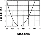
图10示出了本发明抗反射隔膜的反射系数与厚度之间的关系。Fig. 10 shows the relationship between the reflection coefficient and the thickness of the antireflection film of the present invention.
图11示出了本发明的等离子显示器的侧视图.Figure 11 shows a side view of the plasma display of the present invention.
图12示出了本发明的蜂窝式电话的侧视图.Figure 12 shows a side view of the cellular phone of the present invention.
图13示出了本发明的液晶显示器的一个实施例的侧视图。Fig. 13 shows a side view of an embodiment of the liquid crystal display of the present invention.
图14示出了本发明的液晶显示器的另一个实施例的侧视图。Fig. 14 shows a side view of another embodiment of the liquid crystal display of the present invention.
图15示出了本发明的液晶显示器的另一个实施例的侧视图。Fig. 15 shows a side view of another embodiment of the liquid crystal display of the present invention.
附图标记的描述Description of reference signs
1——板1 - board
2——涂覆溶液2 - Coating solution
3——气泡3 - Bubbles
4——孔4 - hole
5、9——本发明的抗反射隔膜5, 9——Anti-reflective diaphragm of the present invention
6——装有本发明抗反射隔膜的温室6—Greenhouse equipped with anti-reflection membrane of the present invention
7——植物罐7 - Plant Pots
8——番茄秧苗8 - tomato seedlings
10——聚碳酸酯板10——polycarbonate plate
11——保护层11 - protective layer
12——记录层12 - Recording layer
13——监视器13 - Monitor
14——隔板14 - clapboard
15——在两侧上涂覆有抗反射隔膜的丙烯酸树脂板15 - Acrylic resin plate coated with anti-reflection film on both sides
16、20——偏振板16, 20 - Polarizing plate
17——显示屏17 - display screen
18——丙烯树脂板18 - acrylic resin board
19——涂覆有抗反射隔膜的玻璃板19 - Glass plate coated with antireflection film
21——操作部分21——Operation part
22——涂覆有抗反射隔膜的玻璃板22—Glass plate coated with anti-reflection film
23——表面电极23 - surface electrode
24——上部光子-电子转换器24 - Upper photon-to-electron converter
25——中间透明电极25——Middle transparent electrode
26——下部光子-电子转换器26 - lower photon-to-electron converter
27——底部电极27 - bottom electrode
115——孔115 - hole
116、145、147、155、156、163、165、166——抗反射隔膜116, 145, 147, 155, 156, 163, 165, 166 - anti-reflection diaphragm
141——荧光元件141 - fluorescent element
142——背面玻璃板142——Rear glass plate
143——前侧玻璃板143——Front glass plate
144——前过滤器144 - front filter
151、161——板151, 161 - board
145、152——氟基抗反射隔膜145, 152——fluorine-based anti-reflective diaphragm
153、16、174——偏振板153, 16, 174 - polarizing plate
154——前侧板154——front side panel
164——丙烯树脂板164——acrylic resin board
167——有机层167 - organic layer
171——玻璃板171—glass plate
172——滤色器172 - color filter
173——液晶层173 - liquid crystal layer
175——扩散片175——Diffuser
176——棱镜片176——prism sheet
177——扩散板177——diffusion plate
178——冷阴极荧光灯管178——Cold-cathode fluorescent lamp
具体实施方式 Detailed ways
下面将参照附图描述本发明的实施例和示例,所述实施例和示例决不是限制本发明,并且在不脱离本发明精神和保护范围的情况下可作出改变。Embodiments and examples of the present invention will be described below with reference to the accompanying drawings, which by no means limit the present invention and can be changed without departing from the spirit and scope of the present invention.
本发明的抗反射隔膜至少由无机氧化物微粒和粘合剂构成,其中粘合剂用于粘接隔膜.所述隔膜基本上是通过将包含无机氧化物微粒、粘合剂和溶剂的混合物涂布在板上之后将其加热为膜而制造的。当粘合剂为热固性材料(例如,硅溶胶,或用于环氧或三聚氰胺树脂的单体)时,它加入有少量催化剂以加速隔膜的热固。所述抗反射隔膜可通过用于形成单层或多层隔膜的工艺形成。The antireflective membrane of the present invention is composed of at least inorganic oxide particles and a binder, wherein the binder is used to bond the membrane. The membrane is basically formed by coating a mixture containing inorganic oxide particles, a binder and a solvent. Manufactured by heating the cloth onto a board to form a film. When the adhesive is a thermosetting material (for example, silica sol, or a monomer for epoxy or melamine resin), it is added with a small amount of catalyst to accelerate the thermosetting of the separator. The anti-reflection membrane may be formed by a process for forming a single-layer or multi-layer membrane.
下面参照图1描述用于形成抗反射隔膜的方法。首先,板1被涂覆以涂覆溶液2以形成涂覆膜。之后,将其加热。这使得溶剂蒸发以便于在膜中留下气泡3。在被冷却之后,这些气泡作为孔3被保留在膜中,从而构成本发明的抗反射隔膜5。A method for forming an antireflective membrane will be described below with reference to FIG. 1 . First, a
图2是示出了本发明抗反射隔膜的一个示例的截面图的照片。它被形成在丙烯酸板上.二氧化硅微粒用作无机氧化物颗粒,而硅溶胶用作粘合剂。丙烯酸板按所述顺序涂覆有低折射系数的隔膜和碳.碳层仅用于在制备样品时保持截面完整,而对本发明抗反射隔膜的效果没有影响。FIG. 2 is a photograph showing a cross-sectional view of one example of the antireflection membrane of the present invention. It was formed on an acrylic plate. Silica microparticles were used as the inorganic oxide particles, while silica sol was used as the binder. The acrylic plate was coated with a low-refractive-index membrane and carbon in the order described. The carbon layer was only used to keep the cross-section intact while preparing the sample and had no effect on the effectiveness of the antireflection membrane of the invention.
图2确认了在低折射系数的抗反射隔膜中几个孔的存在。尽管在形状上不确定,但它们具有大约5到150nm的长轴,其中长轴是指从一端到另一端所画的最长直线的长度.Figure 2 confirms the presence of several holes in the low refractive index antireflective membrane. Although indeterminate in shape, they have a major axis of approximately 5 to 150 nm, where the major axis is the length of the longest straight line drawn from one end to the other.
为了确认隔膜中孔的存在,测量存在于被认为是孔的部分中和固体部分中的元素的强度.在图3中给出了其结果。In order to confirm the presence of pores in the membrane, the intensities of elements present in the portion considered to be pores and in the solid portion were measured. The results are given in Fig. 3.
如图3中所示的,元素,例如,碳、氧和硅在被认为是孔的部分中具有比固体部分中低的强度。As shown in FIG. 3, elements such as carbon, oxygen, and silicon have lower strength in the portion considered to be pores than in the solid portion.
可通过改变作为粘合剂的二氧化硅(折射系数:大约1.5)与孔(折射系数:大约1.0)的比例而控制隔膜的折射系数.The refractive index of the separator can be controlled by changing the ratio of silica (refractive index: about 1.5) as a binder to holes (refractive index: about 1.0).
已知在热固性步骤中溶剂在隔膜中的蒸发有助于孔的形成,也可通过选择适当沸点和热固性处理温度的溶剂而控制孔的形成。Evaporation of the solvent in the membrane during the thermosetting step is known to contribute to pore formation, which can also be controlled by selecting a solvent with an appropriate boiling point and thermosetting processing temperature.
如图2中可看到的趋势,在隔膜最外层表面附近所述孔形成得更为致密。这可令人信服地得出,当被加热以便于热固时开始出现在板上的涂覆溶液中的孔会上升到表面区域。As can be seen in the trend in Figure 2, the pores are more densely formed near the outermost surface of the membrane. This convincingly follows that pores in the coating solution that initially appear on the plate rise to the surface area when heated to facilitate thermosetting.
两层或多层隔膜的叠层结构是整体形成内部孔以及表面区域中的孔的一种选择。这也有助于增强的隔膜强度。Laminates of two or more layers of membranes are an option for the integral formation of internal pores as well as pores in the surface region. This also contributes to enhanced diaphragm strength.
图9示出了该隔膜的横截面图(照片)。该照片示出了分布在抗反射隔膜116内部但较少在表面上延伸的孔。由于较大的不规则性,其上分布有孔的表面整体变得更为粗糙,当用布等擦拭时所述表面易于被擦去。当表面具有更小不规则性时减少了这些问题,从而导致隔膜的物理强度得以提高。Figure 9 shows a cross-sectional view (photograph) of the membrane. The photograph shows pores distributed inside the anti-reflection membrane 116 but less often extending over the surface. Due to the larger irregularities, the surface on which the pores are distributed becomes overall rougher, said surface being easily wiped off when wiped with a cloth or the like. These problems are reduced when the surface has less irregularities, resulting in improved physical strength of the membrane.
接下来,将更详细地描述涂覆溶液和膜制造步骤。Next, the coating solution and film production steps will be described in more detail.
涂覆溶液coating solution
涂覆溶液由粘合剂、无机氧化物微粒和溶剂构成。下面将描述这些成分中的每种。The coating solution consists of a binder, inorganic oxide fine particles, and a solvent. Each of these components will be described below.
(1-1)粘合剂(1-1) Adhesive
可从高透明性的有机或无机高分子量材料以及可聚合成具有高分子量的材料中选择用于涂覆溶液的粘合剂。有机高分子量材料包括热塑性材料。更具体地说,它们包括丙烯树脂、聚苯乙烯、苯乙烯/丙烯共聚物、聚脂树脂、聚氯乙烯、乙烯/醋酸乙烯酯、聚对苯二甲酸乙二醇酯、聚偏二氯乙烯和聚碳酸酯树脂.可聚合成具有高分子量的有机材料包括热固性材料。更具体地说,它们包括具有脂肪族结构的聚酰胺酸衍生物。The binder for the coating solution can be selected from highly transparent organic or inorganic high molecular weight materials and materials polymerizable to have high molecular weight. Organic high molecular weight materials include thermoplastic materials. More specifically, they include acrylic resins, polystyrene, styrene/propylene copolymers, polyester resins, polyvinyl chloride, ethylene/vinyl acetate, polyethylene terephthalate, polyvinylidene chloride And polycarbonate resins. Can be polymerized into organic materials with high molecular weight including thermosetting materials. More specifically, they include polyamic acid derivatives having an aliphatic structure.
无机高分子量材料包括其残余物可水解的硅化合物(通常称之为硅溶胶)和残余物可水解的钛化合物(通常称之为二氧化钛溶胶)。这些是聚合成具有数千分子量的烷氧基硅烷或烷氧基钛烷的化合物,并且可溶解在乙醇基溶剂中.当被加热时,它们可形成为二氧化硅或二氧化钛的粘合剂。Inorganic high molecular weight materials include silicon compounds whose residues are hydrolyzable (usually called silica sol) and residues of which are hydrolyzable titanium compounds (usually called titania sol). These are compounds that polymerize into alkoxysilanes or alkoxytitanes with molecular weights of several thousand and are soluble in ethanol-based solvents. When heated, they form a binder of silica or titania.
可聚合得具有高分子量的无机材料包括具有变化取代基的烷氧基硅烷,例如,氨基、氯基或硫氢基。稍后当描述具有可水解残余物的硅化合物时,将具体描述它们。Inorganic materials that can be polymerized to high molecular weight include alkoxysilanes with varying substituents, for example, amino, chloro, or sulfhydryl. They will be specifically described later when describing silicon compounds having hydrolyzable residues.
硅溶胶可引证为具有可水解残余物的一种硅化合物.当被加热时,它转化为二氧化硅。下面将描述用于形成硅溶胶的一种典型方法。当在弱酸性环境下被加热时,四烷氧基硅烷聚合得具有平均为数千的分子量,这是由于烷氧基被水解为羟基,所述羟基与邻近烷氧基反应从而形成硅-氧-硅键。用于制造硅溶胶的四烷氧基硅烷包括四甲氧基硅烷、四乙氧基硅烷、四丙氧基硅烷、四异丙氧基硅烷、四丁氧基硅烷、以及四异丁氧基硅烷。具有取代烷氧基硅烷基的氯基的硅化合物(例如四氯化硅)也是适用的.Silica sol can be cited as a silicon compound with a hydrolyzable residue. When heated, it transforms into silicon dioxide. A typical method for forming silica sol will be described below. When heated in a mildly acidic environment, tetraalkoxysilanes polymerize to average molecular weights in the thousands due to the hydrolysis of alkoxy groups to hydroxyl groups which react with adjacent alkoxy groups to form silicon-oxygen - Silicon bond. Tetraalkoxysilanes used in the manufacture of silica sols include tetramethoxysilane, tetraethoxysilane, tetrapropoxysilane, tetraisopropoxysilane, tetrabutoxysilane, and tetraisobutoxysilane . Silicon compounds having chlorine groups substituted with alkoxysilyl groups (such as silicon tetrachloride) are also suitable.
除四烷氧基硅烷以外的具有可水解残余物的硅化合物包括具有氨基、氯基或硫氢基的那些。更具体地说,它们包括3-氨基丙基三甲氧基硅烷、3-氨基丙基三乙氧基甲硅烷、N-(2-氨乙酸)-3-氨基丙基三甲氧基硅烷、3-氯丙基三甲氧基硅烷、3-氯丙基甲基二甲氧基硅烷、3-硫氢基丙基三甲氧基硅烷、乙烯基三甲氧基硅烷、3-glycidoxy丙基三甲氧基硅烷、3-glycidoxy丙基甲基二甲氧基甲硅烷以及3-甲基丙烯丙基三甲氧基甲硅烷。Silicon compounds having hydrolyzable residues other than tetraalkoxysilanes include those having amino, chloro, or sulfhydryl groups. More specifically, they include 3-aminopropyltrimethoxysilane, 3-aminopropyltriethoxysilane, N-(2-aminoacetic acid)-3-aminopropyltrimethoxysilane, 3- Chloropropyltrimethoxysilane, 3-chloropropylmethyldimethoxysilane, 3-sulfhydrylpropyltrimethoxysilane, vinyltrimethoxysilane, 3-glycidoxypropyltrimethoxysilane, 3-glycidoxypropylmethyldimethoxysilane and 3-methacrylpropyltrimethoxysilane.
(1-2)无机氧化物微粒(1-2) Inorganic oxide particles
本发明的无机氧化物微粒是无色或白色的硅氧化物、铝氧化物、钛氧化物以及铈氧化物的微粒.当它们为球形时,它们最好具有190nm或更小的平均颗粒尺寸以防止进入隔膜的可见光散射.对于可见光中颗粒的特点,见“Industrial Science of Color”,Yoshinobu Naya,第二版,由Asakura Shoten出版,1984年1月10日,第二页。较大的颗粒可能不适用于显示器,这是因为入射光的可能散射会导致隔膜模糊不清。当它们的形状为线性时,出于与上述相同的原因,它们最好具有190nm的厚度(垂直于纵向方向的横截面的厚度)。初始颗粒的下限尺寸没有限定,只要它们被良好地分散在隔膜中就可以.The inorganic oxide particles of the present invention are colorless or white particles of silicon oxide, aluminum oxide, titanium oxide, and cerium oxide. When they are spherical, they preferably have an average particle size of 190 nm or less. Prevents scattering of visible light entering the diaphragm. For the characteristics of particles in visible light, see "Industrial Science of Color", Yoshinobu Naya, 2nd edition, published by Asakura Shoten, January 10, 1984, p. Larger particles may not be suitable for use in displays due to possible scattering of incident light causing the diaphragm to be hazy. When their shape is linear, they preferably have a thickness of 190 nm (the thickness of the cross section perpendicular to the longitudinal direction) for the same reason as above. The lower limit size of primary particles is not limited as long as they are well dispersed in the separator.
可使用不同形状尺寸的两种或多种类型的无机氧化物微粒.Two or more types of inorganic oxide particles of different shapes and sizes can be used.
应该注意的是,当不充分溶解于溶剂中时,用作粘合剂的具有可水解残余物的硅化合物可使得初始颗粒聚集成更大的次级粒子,从而导致使得隔膜模糊不清的问题.因此最好使用能够良好地分散二氧化硅微粒的溶剂.然而,取决于将使用的板而不能使用这样一种溶剂。在这样的情况下,使用分散剂以良好地分散它们。It should be noted that silicon compounds with hydrolyzable residues used as binders when not sufficiently dissolved in the solvent can cause the primary particles to aggregate into larger secondary particles, leading to the problem of clouding the membrane It is therefore preferable to use a solvent that can disperse silica particles well. However, such a solvent cannot be used depending on the plate to be used. In such cases, dispersants are used to disperse them well.
硅胶适用于二氧化硅微粒.硅胶产品包括有机硅溶胶,例如,Snowtex(Nissan Chemical Industries).这些微粒在表面上具有整体羟基,并且是高亲水性的。而且,包含这些颗粒的抗反射隔膜是亲水性的,同时,具有大约1×10¹⁰到10×1010Ω的低电阻。该级远低于玻璃、或丙烯、聚碳酸酯或PET树脂的电阻的大约1/10,000到1/1,000,000。因此,所述隔膜有效地防止灰尘等沉积于其上,从而使其可广泛地用于各种装置。例如,在透明表面上装有本发明抗反射隔膜的温室等被赐予更多的入射光,从而缩短植物生长时间。图像形成装置可长时间显示清晰图像,甚至当被放置在低湿度房间内时。涂覆有本发明抗反射隔膜的透明板适用于构成内部材料,例如洁净室壁和隔断墙。Silica gel is suitable for silica microparticles. Silica gel products include silicone sols, eg, Snowtex (Nissan Chemical Industries). These microparticles have integral hydroxyl groups on the surface and are highly hydrophilic. Also, the antireflective membrane containing these particles is hydrophilic, and at the same time, has a low resistance of about 1×10 10 to 10×10 10 Ω. This level is well below the resistance of glass, or about 1/10,000 to 1/1,000,000 of the resistance of acrylic, polycarbonate, or PET resins. Therefore, the diaphragm effectively prevents dust and the like from being deposited thereon, thereby making it widely applicable to various devices. For example, greenhouses and the like equipped with the anti-reflection film of the present invention on transparent surfaces are given more incident light, thereby shortening the growing time of plants. The image forming device can display clear images for a long time, even when placed in a room with low humidity. The transparent panels coated with the antireflective membranes according to the invention are suitable for constituting interior materials such as clean room walls and partition walls.
而且,如稍后描述的,当用具有烷氧基硅烷基的全氟代聚醚或全氟代烷基的防水剂处理时,本发明的抗反射隔膜可具有抗液性.Also, as described later, the antireflection film of the present invention can have liquid repellency when treated with a water repellent of perfluoropolyether or perfluoroalkyl having an alkoxysilyl group.
除二氧化硅以外,由于其低折射系数,氧化铝也是有用材料。例如,表面上具有整体羟基的氧化铝溶胶适用于构成低电阻的隔膜。In addition to silica, alumina is also a useful material due to its low index of refraction. For example, an alumina sol having integral hydroxyl groups on the surface is suitable for constituting a low-resistance separator.
(1-3)溶剂(1-3) Solvent
用作涂覆溶液的有效溶剂将粘合剂溶解或均匀地分散在其中.乙醇基溶剂适用于包含具有可水解残余物的硅化合物作为适合的粘合剂以及适合作为无机氧化物微粒的二氧化硅微粒的涂覆溶液。更具体地说,适用于本发明的乙醇基溶剂包括乙醇、n-丙醇、iso-(异)丙醇、n-丁醇、iso-(异)丁醇、tert--(第三)丁醇、n-戊醇、iso-(异)戊醇、以及tert-(第三)戊醇。乙醇基溶剂是适用的,因为它不易于使得例如聚碳酸酯或丙烯的树脂板膨胀、变形或溶解.当其碳数增加时它趋向于具有更高沸点,当它被更多分支时趋向于具有更低沸点.Used as an effective solvent for the coating solution to dissolve or uniformly disperse the binder in it. Ethanol-based solvents are suitable for containing silicon compounds with hydrolyzable residues as suitable binders and suitable as carbon dioxide for inorganic oxide particles Coating solution for silicon microparticles. More specifically, ethanol-based solvents suitable for use in the present invention include ethanol, n-propanol, iso-(iso)propanol, n-butanol, iso-(iso)butanol, tert-(tertiary)butanol alcohol, n-pentanol, iso-(iso)pentanol, and tert-(tertiary)pentanol. An ethanol-based solvent is suitable because it does not easily swell, deform, or dissolve a resin plate such as polycarbonate or acrylic. It tends to have a higher boiling point as its carbon number increases, and tends to have a higher boiling point when it is more branched. has a lower boiling point.
(2)膜制造方法(2) Membrane manufacturing method
本发明的低折射系数隔膜是通过预处理板、涂布涂覆溶液以在其上形成膜并且加热所述膜形成的。也可通过用于形成单层或多层隔膜的工艺形成本发明的低折射系数隔膜.而且,加热步骤可伴随有后处理以提高隔膜的耐磨损性.下面将详细描述这些步骤.The low-refractive-index separator of the present invention is formed by pretreating a plate, applying a coating solution to form a film thereon, and heating the film. The low-refractive-index separator of the present invention can also be formed by the process used to form a single-layer or multi-layer separator. Also, the heating step can be accompanied by a post-treatment to improve the abrasion resistance of the separator. These steps will be described in detail below.
(2-1)预处理(2-1) Preprocessing
预处理步骤清洁一块板以提高其可湿性.这将均匀地将涂覆溶液沉积到板上。The pretreatment step cleans a board to improve its wettability. This will evenly deposit the coating solution onto the board.
(i)板清洁(i) Plate cleaning
在板清洁步骤中,使用可良好地溶解板上的灰尘或将所述灰尘从板上去除的溶剂、清洁剂等。当板是由树脂(例如丙烯或聚碳酸酯)制成的时,例如,乙醇基溶剂(例如,甲醇、乙醇、丙醇或丁醇)比溶解表面从而使之模糊不清的溶剂(例如,四氢呋喃或二氧杂环乙烷)更适合。当板是由玻璃制成的时,将所述板浸在基本溶液(例如,氢氧化钠水溶液)以略微蚀刻表面可去除灰尘。In the board cleaning step, a solvent, a detergent, or the like that can well dissolve dust on the board or remove the dust from the board is used. When the plate is made of a resin such as acrylic or polycarbonate, ethanol-based solvents (e.g., methanol, ethanol, propanol, or butanol) are more effective than solvents that dissolve the surface thereby making it cloudy (e.g., tetrahydrofuran or dioxane) are more suitable. When the plate is made of glass, dust can be removed by immersing the plate in a basic solution (for example, an aqueous solution of sodium hydroxide) to slightly etch the surface.
(ii)板可湿性的提高(ii) Improvement of board wettability
提高板可湿性容许涂覆溶液被更均匀地涂布在表面上,减小膜厚度波动并且提高板上隔膜的光学特性.还增强了隔膜与板的粘附性,导致提高的隔膜强度。可通过借助于适当的装置(例如等离子辐射体)进行的表面修正或使用酸溶液或基本溶液等进行的化学修正提高板可湿性。Improving plate wettability allows the coating solution to be spread more evenly on the surface, reduces film thickness fluctuations and improves optical properties of the separator on the plate. Adhesion of the separator to the plate is also enhanced, resulting in increased strength of the membrane. The plate wettability can be increased by surface modification by means of suitable means such as plasma radiators or chemical modification with acid solutions or base solutions or the like.
·借助于装置进行的表面修正·Surface modification with the aid of devices
落于该范畴的方法包括氧等离子照射、暴露于臭氧环境以及UV照射。每种方法取决于作用在板表面上以形成羟基或羧基的活性氧.这些基团是亲水性的,并且它们被形成于其上的表面将具有提高的可湿性。UV照射通过UV使得空气中的氧激发为活性状态以进行表面修正.因此,它带来与通过氧等离子照射或暴露于臭氧环境相似的效果.氩等离子照射也可用于进行表面修正。Methods falling into this category include oxygen plasma irradiation, exposure to an ozone environment, and UV irradiation. Each method depends on reactive oxygen species acting on the surface of the plate to form hydroxyl or carboxyl groups. These groups are hydrophilic and the surface on which they are formed will have increased wettability. UV irradiation excites oxygen in the air to an active state by UV for surface modification. Therefore, it brings similar effects to irradiation by oxygen plasma or exposure to an ozone environment. Argon plasma irradiation can also be used for surface modification.
·化学修正·Chemical correction
当被浸在氢氧化钠水溶液中时玻璃具有提高的可湿性,这是由于表面上的硅-氧键被破坏以形成氢氧化物基团。Glass has enhanced wettability when immersed in aqueous sodium hydroxide solution due to the breakdown of silicon-oxygen bonds on the surface to form hydroxide groups.
(2-2)涂覆方法(2-2) Coating method
用于涂覆板的方法包括(但不局限于)旋涂法、浸渍涂布法、杆涂布法、通过涂抹器涂覆、喷涂以及浇涂法。为了将隔膜控制在适当厚度下,对于各种涂覆方法需要选择正确的涂覆溶液浓度和条件.影响隔膜厚度的条件是用于旋涂法的旋转速度和时间、用于浸渍涂布法的浸渍时间和拉出速度、用于杆涂布法的杆的表面上的槽深度、通过涂抹器涂覆的间隙尺寸、喷涂的喷雾移动速度、以及浇涂法下板保持的角度和所使用的涂覆溶液的质量。Methods for coating the panels include, but are not limited to, spin coating, dip coating, rod coating, coating by applicator, spray coating, and flow coating. In order to control the diaphragm at an appropriate thickness, it is necessary to select the correct concentration and conditions of the coating solution for each coating method. The conditions that affect the thickness of the diaphragm are the rotation speed and time for the spin coating method, and the time for the dip coating method. Dipping time and pull-out speed, groove depth on the surface of the rod for the rod coating method, gap size for application by the applicator, spray moving speed for spray application, and the angle at which the plate is held under the flow coating method and the used The quality of the coating solution.
最好将目标隔膜厚度设定在60到190nm下。理论上来说,在相当于λ/4n的隔膜厚度t下反射系数达到最小值,其中λ是入射光的波长,n是入射光通过其进入的媒体(透明板,或本发明的抗反射隔膜)的折射系数。It is preferable to set the target membrane thickness at 60 to 190 nm. Theoretically, the reflection coefficient reaches a minimum value at a membrane thickness t corresponding to λ/4n, where λ is the wavelength of the incident light, and n is the medium through which the incident light enters (transparent plate, or anti-reflection membrane of the present invention) the refraction coefficient.
当入射光是可见光(波长:380到760nm)并且使用具有从作为媒体的空气的折射系数(折射系数:大约1.0)到较高折射系数(大约1.7)的透明玻璃板的折射系数范围内的折射系数的材料时,期望的最小隔膜厚度为380/(4×1.7)=56nm.当入射光具有可见范围内的波长时,低于56nm的隔膜厚度可能不会充分地进行反射。考虑到实际制造工艺中出现的隔膜厚度分布,最好将目标隔膜厚度设定在略大于56nm的60nm。另一方面,期望的最大隔膜厚度为760/(4×1.0)=190nm.基于上述考虑,本发明的隔膜厚度最好在60到190nm的范围内。发光系数在个体之间改变。在适应光的相对发光度曲线(见“IndustrialScience of Color”,Yoshinobu Naya,第二版,由Asakura Shoten出版,1984年1月10日,第4到8页)中相对谱敏感度达到最大值的波长(λ)为大约555nm.换句话说,在明亮环境下人类的发光度达到最大值的波长为大约555nm。理论上来说,抗反射隔膜的折射系数将反射系数降低到0%取决于其上形成有隔膜的板的折射系数,这是由于它是板折射系数的平方根。适用于显示设备(例如,监视器)的板的材料包括玻璃,以及丙烯和PET树脂.当分别形成在玻璃板(折射系数:1.50到1.54)、丙烯树脂板(1.49)和PET树脂板(1.56)上时,抗反射隔膜最好具有1.22到1.24,1.22和1.25的折射系数.基于上述考虑,当其形成在折射系数为1.5的板上并且光线具有555nm的波长时,抗反射隔膜理论上可将光线反射降低到0%.未涂覆的板在一侧上具有大约4%的反射系数,并且可将反射系数降至4%或更小的抗反射隔膜厚度在90到140nm的范围内。图10示出了在上述条件下反射系数与隔膜厚度之间的关系。When the incident light is visible light (wavelength: 380 to 760nm) and using a refractive index range from that of air as a medium (refractive index: about 1.0) to a transparent glass plate with a higher refractive index (about 1.7) The desired minimum membrane thickness is 380/(4×1.7)=56nm for materials with a coefficient of . When the incident light has a wavelength in the visible range, a membrane thickness below 56nm may not reflect sufficiently. Considering the membrane thickness distribution occurring in the actual manufacturing process, it is better to set the target membrane thickness at 60nm which is slightly larger than 56nm. On the other hand, the desired maximum membrane thickness is 760/(4×1.0)=190 nm. Based on the above considerations, the membrane thickness of the present invention is preferably in the range of 60 to 190 nm. The luminescence coefficient varies between individuals. In the light-adapted relative luminosity curve (see "Industrial Science of Color", Yoshinobu Naya, 2nd edition, published by Asakura Shoten, January 10, 1984, pages 4 to 8) the relative spectral sensitivity reaches the maximum The wavelength (λ) is about 555 nm. In other words, the wavelength at which the luminosity of humans reaches a maximum in a bright environment is about 555 nm. Theoretically, the refractive index of the anti-reflective membrane to reduce the reflectance to 0% depends on the refractive index of the plate on which the membrane is formed, since it is the square root of the plate's refractive index. Materials suitable for plates of display devices such as monitors include glass, and acrylic and PET resins. When formed on glass plates (refractive index: 1.50 to 1.54), acrylic resin plates (1.49) and PET resin plates (1.56 ), the anti-reflection film preferably has a refractive index of 1.22 to 1.24, 1.22 and 1.25. Based on the above considerations, when it is formed on a plate with a refractive index of 1.5 and the light has a wavelength of 555nm, the anti-reflection film can theoretically be Reduce light reflection to 0%. Uncoated panels have approximately 4% reflectance on one side, and anti-reflective membrane thicknesses that can reduce reflectance to 4% or less are in the range of 90 to 140nm. FIG. 10 shows the relationship between the reflectance and the thickness of the diaphragm under the above conditions.
(2-3)加热(2-3) Heating
涂覆板被加热以通过蒸发去除溶剂,或者加速聚合作用。当热固性树脂用作粘合剂时,应在树脂的热固温度或更高的温度下执行加热.因此必须将溶剂、板和板材料选择得满足这些要求。所述板最好由与用于隔膜的材料相似的材料制成。Coated panels are heated to remove solvent by evaporation, or to accelerate polymerization. When a thermosetting resin is used as an adhesive, heating should be performed at the thermosetting temperature of the resin or higher. Therefore, the solvent, board and board material must be selected to meet these requirements. The plate is preferably made of a material similar to that used for the diaphragm.
(2-4)后处理的描述(2-4) Description of post-processing
当其被热固时,制成了抗反射隔膜。当涂覆以具有抗液性的氟化合物时,其表面将具有提高的污垢热阻性。然而,具有抗液性的氟化合物层应充分薄以不会降低隔膜的抗反射能力。抗液层的厚度为6nm或更低以便于在人类的发光度保持在高水平的555nm的光线波长下将对隔膜反射系数的不利作用控制在1%以下。When it is heat-set, an anti-reflective membrane is made. When coated with a liquid-repellent fluorochemical, the surface will have improved thermal resistance to fouling. However, the liquid-repellent fluorochemical layer should be sufficiently thin so as not to reduce the anti-reflection capability of the membrane. The thickness of the liquid repellent layer is 6nm or less in order to control the adverse effect on the reflectance of the diaphragm to less than 1% at the light wavelength of 555nm where the luminosity of human beings is kept at a high level.
可通过以下两种方法中之一形成具有抗液性的氟化合物的涂覆层。The coating layer of the fluorine compound having liquid repellency can be formed by one of the following two methods.
·涂覆以具有抗液性的氟化合物层・Coated with a liquid-repellent fluorine compound layer
该方法为抗反射隔膜涂覆以具有抗液性的氟化合物层.被涂覆的隔膜显示出抗液性.应该注意的是,为低电阻隔膜涂覆以抗液性氟化合物具有提高的表面电阻,可加速灰尘等沉积在其上。This method coats an antireflective diaphragm with a liquid-repellent fluorochemical layer. The coated diaphragm exhibits liquid repellency. It should be noted that coating a low-resistance diaphragm with a liquid-repellent fluorochemical has an improved surface Resistance, which can accelerate the deposition of dust etc. on it.
用于形成抗液层的材料包括CYTOP(Asahi Glass)和INT304VC(INT屏幕).这些材料中的每种都用溶剂稀释,涂布在板上并且将其加热以通过蒸发去除溶剂,以便于形成抗液层.取决于环境因素在加热步骤中可使其热固。Materials used to form the liquid-repellent layer include CYTOP (Asahi Glass) and INT304VC (INT Screen). Each of these materials is diluted with a solvent, coated on a plate and heated to remove the solvent by evaporation to facilitate formation Liquid-resistant layer. Depending on environmental factors, it can be heat-set during a heating step.
·使全氟代聚醚与全氟代烷化合物与隔膜键合・Bond perfluoropolyether and perfluoroalkane compounds to the separator
这种方法粘接在终端处具有烷氧基硅烷基团等的全氟代聚醚或全氟代烷基化合物,所述化合物可被粘接于抗反射隔膜。更具体地说,由化学式5表示的化合物可被粘接于抗反射隔膜。This method bonds a perfluoropolyether or perfluoroalkyl compound having an alkoxysilane group or the like at the terminal, which can be bonded to an antireflection film. More specifically, the compound represented by Chemical Formula 5 may be adhered to the antireflection film.
(化学式5)(chemical formula 5)
[F{CF(CF3)-CF2O}n-CF(CF3)]-X-Si(OR)3 n=6到48[F{CF(CF 3 )-CF 2 O} n -CF(CF 3 )]-X-Si(OR) 3 n=6 to 48
{F(CF2CF2CF2O)n}-X-Si(OR)3 n=6到48{F(CF 2 CF 2 CF 2 O) n }-X-Si(OR) 3 n=6 to 48
{H(CF2)n}-Y-Si(OR)3 n=1到16{H(CF 2 ) n }-Y-Si(OR) 3 n=1 to 16
{F(CF2)n}-Y-Si(OR)3 n=1到16{F(CF 2 ) n }-Y-Si(OR) 3 n=1 to 16
其中,X为全氟代聚醚链与烷氧基硅烷残余物相互键合的位点,Y为全氟代烷基链与烷氧基硅烷残余物相互键合的位点,以及R为烷基。Wherein, X is the site where the perfluoropolyether chain and the alkoxysilane residue are bonded to each other, Y is the site where the perfluoroalkyl chain and the alkoxysilane residue are bonded to each other, and R is an alkoxysilane residue. base.
所述化合物没有完全覆盖抗反射隔膜表面,而是像生长在地面上的草一样分布在位置中。因此,甚至当涂覆有上述化合物时,低电阻隔膜(1011Ω或更小)也可保持其低电阻。而且,在隔膜表面上形成全氟代聚醚或全氟代烷基链具有提高的润滑性,缓和了表面上由于磨损导致的物理损坏。因此,涂覆隔膜表面提高了其抗磨损性。The compound does not completely cover the surface of the antireflective membrane, but is distributed in places like grass growing on the ground. Therefore, a low-resistance separator (10 11 Ω or less) can maintain its low resistance even when coated with the above compound. Furthermore, the formation of perfluoropolyether or perfluoroalkyl chains on the surface of the membrane provides enhanced lubricity, mitigating physical damage on the surface due to abrasion. Thus, coating the surface of the diaphragm increases its wear resistance.
(2-5)用于后处理的抗液剂(2-5) Anti-liquid agent for post-treatment
下面将描述用于本发明的抗液剂和涂覆方法。The liquid repellent and coating method used in the present invention will be described below.
抗液剂Liquid repellant
更具体地说,在终端处具有烷氧基硅烷基团等的全氟代聚醚或全氟代烷基化合物包括以下化合物1到12:More specifically, perfluoropolyether or perfluoroalkyl compounds having an alkoxysilane group etc. at the terminal include the following
(化学式6)(chemical formula 6)
F{CF(CF3)-CF2O}n-CF(CF3)-CONH-(CH2)3-Si(OCH2CH3)3 F{CF(CF 3 )-CF 2 O} n -CF(CF 3 )-CONH-(CH 2 ) 3 -Si(OCH 2 CH 3 ) 3
n=6到48n=6 to 48
化合物1
(化学式7)(chemical formula 7)
F{CF(CF3)-CF2O}n-CF(CF3)-CONH-(CH2)3-Si(OCH3)3 F{CF(CF 3 )-CF 2 O} n -CF(CF 3 )-CONH-(CH 2 ) 3 -Si(OCH 3 ) 3
n=6到48n=6 to 48
化合物2
(化学式8)(chemical formula 8)
F{CF2CF2CF2O}n-CF2CF2-CONH-(CH2)3-Si(OCH2CH3)3 F{CF 2 CF 2 CF 2 O} n -CF 2 CF 2 -CONH-(CH 2 ) 3 -Si(OCH 2 CH 3 ) 3
n=6到48n=6 to 48
化合物3
(化学式9)(chemical formula 9)
F{CF2CF2CF2O}n-CF2CF2-CONH-(CH2)3-Si(OCH3)3 F{CF 2 CF 2 CF 2 O} n -CF 2 CF 2 -CONH-(CH 2 ) 3 -Si(OCH 3 ) 3
n=6到48n=6 to 48
化合物4Compound 4
(化学式10)(chemical formula 10)
H(CF2)6-CONH-(CH2)3-Si(OCH2CH3)3 H(CF 2 ) 6 -CONH-(CH 2 ) 3 -Si(OCH 2 CH 3 ) 3
化合物5Compound 5
(化学式11)(chemical formula 11)
H(CF2)6-CONH-(CH2)3-Si(OCH3)3 H(CF 2 ) 6 -CONH-(CH 2 ) 3 -Si(OCH 3 ) 3
化合物6
(化学式12)(chemical formula 12)
H(CF2)8-CONH-(CH2)3-Si(OCH2CH3)3 H(CF 2 ) 8 -CONH-(CH 2 ) 3 -Si(OCH 2 CH 3 ) 3
化合物7
(化学式13)(chemical formula 13)
H(CF2)8-CONH-(CH2)3-Si(OCH3)3 H(CF 2 ) 8 -CONH-(CH 2 ) 3 -Si(OCH 3 ) 3
化合物8
(化学式14)(chemical formula 14)
F(CF2)6(CH2)2-Si(OCH3)3 F(CF 2 ) 6 (CH 2 ) 2 -Si(OCH 3 ) 3
化合物9Compound 9
(化学式15)(chemical formula 15)
F(CF2)8-(CH2)2-Si(OCH3)3 F(CF 2 ) 8 -(CH 2 ) 2 -Si(OCH 3 ) 3
化合物10Compound 10
(化学式16)(chemical formula 16)
F(CF2)6-(CH2)2-Si(OCH2CH3)3 F(CF 2 ) 6 -(CH 2 ) 2 -Si(OCH 2 CH 3 ) 3
化合物11Compound 11
(化学式17)(chemical formula 17)
F(CF2)8-(CH2)2-Si(OCH2CH3)3 F(CF 2 ) 8 -(CH 2 ) 2 -Si(OCH 2 CH 3 ) 3
化合物12Compound 12
在这些化合物中,化合物1到8可通过以下所述的方法制造.化合物9到12可分别由Hydrus Chemical作为1H,1H,2H,2H-全氟代辛基三甲氧基硅烷、1H,1H,2H,2H-全氟代辛基三乙氧基硅烷、1H,1H,2H,2H-全氟代癸基三甲氧基硅烷、以及1H,1H,2H,2H-全氟代癸基三乙氧基硅烷提供。Daikin Industries’OPTOOL DSX是另一种商业产品。化合物1到4具有作为全氟代聚醚的氟链。当长时间(大约1000小时)浸入在液体(例如除水外还有机油或汽油)中时,由具有氟链的化合物构成的抗液性隔膜显示出在抗液性方面的较少降低(降低5°或更低)。这些化合物由以下通式表示:Among these compounds, compounds 1 to 8 can be produced by the methods described below. Compounds 9 to 12 can be obtained from Hydrus Chemical respectively as 1H, 1H, 2H, 2H-perfluorooctyltrimethoxysilane, 1H, 1H, 2H,2H-Perfluorooctyltriethoxysilane, 1H,1H,2H,2H-Perfluorodecyltrimethoxysilane, and 1H,1H,2H,2H-Perfluorodecyltriethoxy base silane provided. Daikin Industries' OPTOOL DSX is another commercial product.
(化学式18)(chemical formula 18)
[F{CF(CF3)-CF2O}n-CF(CF3)]-X-Si(OR)3 n=6到48[F{CF(CF 3 )-CF 2 O} n -CF(CF 3 )]-X-Si(OR) 3 n=6 to 48
{F(CF2CF2CF2O)n}-X-Si(OR)3 n=6到48{F(CF 2 CF 2 CF 2 O) n }-X-Si(OR) 3 n=6 to 48
其中,X为全氟代聚醚链与烷氧基硅烷残余物相互键合的位点,R为烷基。Wherein, X is the site where the perfluoropolyether chain and the alkoxysilane residue are bonded to each other, and R is an alkyl group.
化合物5到12示出了在几乎浸入到板的机油或汽油中之前当长时间(大约1000小时)浸入时与水的接触角从大约110°下减小。Compounds 5 to 12 show that the contact angle with water decreases from about 110° when immersed for a long time (about 1000 hours) before almost immersing the panel in motor oil or gasoline.
(化合物1的合成)(Synthesis of Compound 1)
首先,将25重量份的DuPont’s Krytox157FS-L(平均分子量:2500)溶解于100重量份的3M’s PF-5080中,向其中加入20重量份的亚硫酰氯。在回流下结合搅拌加热该混合物48小时,之后通过蒸发器去除亚硫酰氯和PF-5080。这产生出25重量份的Krytox157FS-L的酸性氯化物。它与100重量份的PF-5080、3重量份的Chisso’s Sila-Ace S330以及3重量份的三乙基胺相混合,并且在室温下搅拌所得到的混合物20小时。用Showa Chemical Industry’s助滤剂RADIOLITE过滤反应溶液,并且通过蒸发从滤出液中去除PF-5080.这产生出20重量份的化合物1。First, 25 parts by weight of DuPont's Krytox157FS-L (average molecular weight: 2500) was dissolved in 100 parts by weight of 3M's PF-5080, and 20 parts by weight of thionyl chloride was added thereto. The mixture was heated at reflux with stirring for 48 hours after which time the thionyl chloride and PF-5080 were removed by evaporator. This yielded 25 parts by weight of the acid chloride of Krytox 157FS-L. It was mixed with 100 parts by weight of PF-5080, 3 parts by weight of Chisso's Sila-Ace S330, and 3 parts by weight of triethylamine, and the resulting mixture was stirred at room temperature for 20 hours. The reaction solution was filtered with Showa Chemical Industry's filter aid RADIOLITE, and PF-5080 was removed from the filtrate by evaporation. This yielded 20 parts by weight of
(化合物2的合成)(Synthesis of compound 2)
除用3重量份的Chisso’s Sila-Ace S360取代3重量份的Chisso’sSila-Ace S330以外,以与化合物1相同的方式合成化合物2(20重量份)。Compound 2 (20 parts by weight) was synthesized in the same manner as
(化合物3的合成)(Synthesis of compound 3)
除用35重量份的Daikin Industries’s DEMNUM SH(平均分子量:3500)取代25重量份的DuPont’s Krytox157FS-L(平均分子量:2500)以外,以与化合物1相同的方式合成化合物3(30重量份)。Compound 3 (30 parts by weight) was synthesized in the same manner as
(化合物4的合成)(Synthesis of compound 4)
除用3重量份的Chisso’s Sila-Ace S360取代3重量份的Chisso’sSila-Ace S330以及用35重量份的Daikin Industries’s DEMNUM SH(平均分子量:3500)取代25重量份的DuPont’s Krytox157FS-L(平均分子量:2500)以外,以与化合物1相同的方式合成化合物4(30重量份)。Except replacing 3 parts by weight of Chisso's Sila-Ace S330 with 3 parts by weight of Chisso's Sila-Ace S360 and replacing 25 parts by weight of DuPont's Krytox157FS-L (average molecular weight: 3500) with 35 parts by weight of Daikin Industries' DEMNUM SH (average molecular weight: 3500) : 2500), compound 4 (30 parts by weight) was synthesized in the same manner as
(化合物5的合成)(Synthesis of compound 5)
除用3.5重量份的Daikin Industries’s 7H-十二氟代庚酸(平均分子量:346.03)取代25重量份的DuPont’s Krytox157FS-L(平均分子量:2500)以外,以与化合物1相同的方式合成化合物5(3.5重量份)。In addition to replacing 25 parts by weight of DuPont's Krytox157FS-L (average molecular weight: 2500) with 3.5 parts by weight of Daikin Industries' 7H- dodecafluoroheptanoic acid (average molecular weight: 346.03), compound 5 was synthesized in the same manner as compound 1 ( 3.5 parts by weight).
(化合物6的合成)(Synthesis of compound 6)
除用3.5重量份的Daikin Industries’s 7H-十二氟代庚酸(平均分子量:346.03)取代25重量份的DuPont’s Krytox157FS-L(平均分子量:2500)以及用2重量份的Chisso’s Sila-Ace S320取代2重量份的Chisso’sSila-Ace S310以外,以与化合物1相同的方式合成化合物6(3.5重量份)。In addition to replacing 25 parts by weight of DuPont's Krytox157FS-L (average molecular weight: 2500) with 3.5 parts by weight of Daikin Industries' 7H- dodecafluoroheptanoic acid (average molecular weight: 346.03) and replacing 2 with 2 parts by weight of Chisso's Sila-Ace S320 Compound 6 (3.5 parts by weight) was synthesized in the same manner as
(化合物7的合成)(Synthesis of Compound 7)
除用4.5重量份的Daikin Industries’s 9H-十六氟代壬酸(平均分子量:446.07)取代25重量份的DuPont’s Krytox157FS-L(平均分子量:2500)以外,以与化合物1相同的方式合成化合物7(4.5重量份)。In addition to replacing 25 parts by weight of DuPont's Krytox157FS-L (average molecular weight: 2500) with 4.5 parts by weight of Daikin Industries' 9H-hexadecafluorononanoic acid (average molecular weight: 446.07),
(化合物8的合成)(Synthesis of Compound 8)
除用4.5重量份的Daikin Industries’s 9H-十六氟代壬酸(平均分子量:446.07)取代25重量份的DuPont’s Krytox157FS-L(平均分子量:2500)以及用2重量份的Chisso’s Sila-Ace S20取代2重量份的Chisso’sSila-Ace S310以外,以与化合物1相同的方式合成化合物8(4.5重量份)。In addition to replacing 25 parts by weight of DuPont's Krytox157FS-L (average molecular weight: 2500) with 4.5 parts by weight of Daikin Industries' 9H-hexadecafluorononanoic acid (average molecular weight: 446.07) and replacing 2 with 2 parts by weight of Chisso's Sila-Ace S20 Compound 8 (4.5 parts by weight) was synthesized in the same manner as
(b)形成抗液性隔膜的方法(b) Method of forming a liquid-resistant separator
下面将描述用于使用在终端处具有烷氧基硅烷基团等的全氟代聚醚或全氟代烷基化合物形成抗液性隔膜的方法。首先,将在终端处具有烷氧基硅烷基团的全氟代聚醚或全氟代烷基化合物溶解在溶剂中.溶剂的浓度通常大约在重量的0.01到1.0%,尽管溶液的涂布方法不同。本发明使用的氟基溶剂包括FC-72、FC-77、PF-5060、PF-5080、HFE-7100和HFE-7200(3M),以及Vertrel(DuPont)。这样,就制备出溶解有全氟代聚醚或全氟代烷基化合物的溶液(在下文中称之为抗液性处理溶液)。A method for forming a liquid-resistant separator using a perfluoropolyether or a perfluoroalkyl compound having an alkoxysilane group or the like at the terminal will be described below. First, a perfluoropolyether or perfluoroalkyl compound having an alkoxysilane group at the terminal is dissolved in a solvent. The concentration of the solvent is usually about 0.01 to 1.0% by weight, although the solution coating method different. Fluorine-based solvents used in the present invention include FC-72, FC-77, PF-5060, PF-5080, HFE-7100 and HFE-7200 (3M), and Vertrel (DuPont). Thus, a solution in which perfluoropolyether or perfluoroalkyl compound is dissolved (hereinafter referred to as a liquid repellent treatment solution) is prepared.
接着,通过普通方法(例如浸渍涂覆或旋涂法)为抗反射隔膜涂覆以抗液性处理溶液。之后,对其进行加热。Next, the antireflection membrane is coated with a liquid repellent treatment solution by an ordinary method such as dip coating or spin coating. After that, it is heated.
(3)可应用区域(3) Applicable area
本发明的抗反射隔膜可被形成在透明板上,例如玻璃或聚碳酸酯或丙烯树脂的透明板上。The antireflective membrane of the present invention may be formed on a transparent plate, such as glass or polycarbonate or acrylic transparent plate.
因此,它可应用于需要有效摄取阳光同时使得反射最小化的那些区域。这些区域包括用于使得植物稳定并迅速生长的温室的透明壁、以及水族箱的透明壁,这是因为它可有效地控制反射并且增强所要观察或观赏的动物、植物、昆虫、鱼类等的可视性。Therefore, it can be applied in those areas where effective sunlight intake is required while minimizing reflections. These areas include the transparent walls of greenhouses for stabilizing and rapidly growing plants, and the transparent walls of aquariums because it effectively controls reflections and enhances the visibility of animals, plants, insects, fish, etc. to be observed or viewed. visibility.
相似地,它可应用于显示设备(例如,用于电视机、蜂窝式电话、汽车导航系统、流速计等的液晶显示器、等离子和有机电致发光(EL)显示器),这是由于它可有效地控制光线的反射并且增强可视性。它适用于被布置在这些设备的显示屏的最外层表面。Similarly, it can be applied to display devices (for example, liquid crystal displays, plasma and organic electroluminescent (EL) displays for televisions, cellular phones, car navigation systems, flow meters, etc.), since it can effectively Control the reflection of light and enhance visibility. It applies to the outermost surface of the display screens arranged on these devices.
它还适用于这样的区域,即,用抗反射隔膜覆盖太阳能电池板表面以增强太阳能转换效率。它仍然适用于光学存储媒体的最外层表面,这是由于它不但可有效地吸收太阳光而且还可吸收激光束等。It is also suitable for areas where the surface of the solar panel is covered with an anti-reflection film to enhance solar energy conversion efficiency. It is still suitable for the outermost surface of optical storage media because it absorbs not only sunlight but also laser beams etc. efficiently.
除其高抗反射能力以外,抗反射隔膜的特征还在于其低电阻,从而防止其上的沉积等,并且甚至当在冬季的低湿度环境下或多尘环境下工作时也可保持高透光性和可视性。而且,当赋予其抗液性时,它具有提高的防污特性,从而导致进一步提高的透光性和可视性.这些特征使得本发明的抗反射隔膜可应用于构成内部材料,例如,洁净室壁和隔断墙。In addition to its high anti-reflection capability, anti-reflection membranes are also characterized by their low electrical resistance, preventing deposits etc. on them, and maintain high light transmission even when working in low-humidity or dusty environments in winter and visibility. Moreover, when endowed with liquid repellency, it has enhanced antifouling properties, resulting in further enhanced light transmission and visibility. These features make the antireflective membrane of the present invention applicable to constituting interior materials, for example, clean Room walls and partition walls.
(i)控制反射(i) Control reflexes
甚至当形成在透明板(例如,玻璃或聚碳酸酯或丙烯树脂的透明板)上时,本发明的抗反射隔膜可保持其透明性.因此本发明的抗反射隔膜可应用于显示设备(例如,用于电视机、蜂窝式电话、汽车导航系统、流速计等的液晶显示器、等离子和有机电致发光(EL)显示器)。它还可应用于透镜、机动车车窗、以及机动车照明装置和发光元件的最外层元件。Even when formed on a transparent plate (such as a transparent plate of glass or polycarbonate or acrylic resin), the antireflection film of the present invention can maintain its transparency. Therefore, the antireflection film of the present invention can be applied to display devices such as , Liquid crystal displays, plasma and organic electroluminescence (EL) displays for televisions, cellular phones, car navigation systems, flow meters, etc.). It can also be applied to lenses, automotive windows, and outermost elements of automotive lighting and lighting elements.
(ii)控制显示设备的外部和/或内部光线的反射(ii) control the reflection of external and/or internal light of the display device
当形成在具有与空气的接触面的至少一个平面处时,本发明的抗反射隔膜被布置在光源与最外层板表面的最外层表面之间,并且可控制显示设备内部的光线的反射。当形成在最外层表面上时,它可控制外部光线的反射。它可应用于任何隔膜/元件组合,只要所述元件在其表面与空气之间具有分界面就可以。当形成在除最外层表面以外的表面上时它可具有比形成在最外层表面上时低的物理强度,只要其满足用于控制光线反射的目标能力就可以。When formed at at least one plane having a contact surface with air, the antireflection film of the present invention is disposed between the light source and the outermost surface of the outermost board surface, and can control reflection of light inside the display device . When formed on the outermost surface, it controls the reflection of external light. It is applicable to any membrane/element combination as long as the element has an interface between its surface and air. It may have a lower physical strength when formed on a surface other than the outermost surface than when formed on the outermost surface as long as it satisfies the target capability for controlling light reflection.
当在光线出口、光线入口和前玻璃表面的至少一个上装有本发明的抗反射隔膜时,装有隔着空气层面对前板的光线的出口侧的前过滤器的等离子显示器可控制外部和/或内部光线的反射.当在最外层表面上装有本发明的抗反射隔膜时,缺乏具有与空气层的接触面(即界面)(例如,在前板与前过滤器之间没有空气层或者没有前过滤器)的内部元件的显示设备可控制外部光线的反射。When at least one of the light exit, the light entrance, and the front glass surface is equipped with the anti-reflection membrane of the present invention, the plasma display equipped with the front filter on the exit side of the light facing the front plate across the air layer can control the exterior and/or Or the reflection of internal light. When the anti-reflection membrane of the present invention is housed on the outermost surface, the lack of a contact surface (ie interface) with the air layer (for example, there is no air layer between the front plate and the front filter or A display device with internal elements without a front filter) to control the reflection of external light.
当在具有与空气层的接触面的偏振板或透明板上装有本发明的抗反射隔膜时,其偏振板未粘接于一对之间布置有液晶层的透明板的每个上的液晶显示器可控制内部光线的反射。A liquid crystal display whose polarizing plate is not bonded to each of a pair of transparent plates with a liquid crystal layer disposed therebetween when the antireflection film of the present invention is mounted on a polarizing plate or a transparent plate having a contact surface with an air layer Reflection of internal light can be controlled.
(iii)提高的亮度(iii) Increased brightness
取决于其目的,当在一侧或两侧上部分或全部地装有本发明的抗反射隔膜时,构成背景光单元的元件可具有提高的亮度,从而增强透光性。它可应用于任何隔膜/元件组合,只要所述元件在其表面与空气之间具有分界面就可以。当在光波导上装有本发明的抗反射隔膜时,在板旁边具有光源并且通过光波导将光线指引到目标区域的显示器(例如,小到中型液晶显示器)可具有提高的亮度。当在光源上装有本发明的抗反射隔膜时,也可具有提高的亮度。Depending on the purpose thereof, when the anti-reflection membrane of the present invention is partially or completely provided on one side or both sides, the elements constituting the backlight unit can have increased brightness, thereby enhancing light transmittance. It is applicable to any membrane/element combination as long as the element has an interface between its surface and air. Displays (eg, small to mid-sized liquid crystal displays) that have a light source next to the panel and direct light to a target area through the light guide can have enhanced brightness when the antireflective membrane of the present invention is mounted on the light guide. Increased brightness is also possible when the antireflection film of the present invention is provided on the light source.
示例example
下面将通过示例详细描述本发明。然而,应该理解的是,本发明的保护范围决不受示例限制。The present invention will be described in detail below by way of examples. However, it should be understood that the scope of the present invention is by no means limited by the examples.
(示例1)(Example 1)
首先,将描述用于在玻璃板上形成抗反射隔膜的方法.First, a method for forming an antireflection film on a glass plate will be described.
(1)在其涂覆有用于形成抗反射隔膜的溶液之前,板的预处理(1) Pretreatment of the board before it is coated with the solution for forming the antireflective membrane
用从低电压汞灯中发射出的强度为10mW的紫外线照射玻璃板(尺寸为100×100×1.1mm,折射系数:1.50)5分钟。这将板表面与水的接触角从30到35°减小到10°或更小。A glass plate (dimensions: 100 x 100 x 1.1 mm, refractive index: 1.50) was irradiated with ultraviolet light at an intensity of 10 mW emitted from a low-voltage mercury lamp for 5 minutes. This reduces the contact angle of the plate surface with water from 30 to 35° to 10° or less.
(2)用于形成抗反射隔膜的溶液的制备(2) Preparation of a solution for forming an antireflection membrane
通过将3重量份的硅溶胶溶液(用磷酸保持酸性,溶剂:水/乙醇(1/4),包含2.5%重量份的烷氧基硅烷)作为粘合剂和4重量份的二氧化硅分散剂作为无机氧化物微粒(IPA-ST,Nissan ChemicalIndustries,包含30%重量份的固体)与60重量份的乙醇相混合制备用于形成抗反射隔膜的涂覆溶液(在下文中称之为抗反射隔膜形成溶液).它具有80℃的沸点.By using 3 parts by weight of silica sol solution (keep acidic with phosphoric acid, solvent: water/ethanol (1/4), containing 2.5% by weight of alkoxysilane) as a binder and 4 parts by weight of silicon dioxide dispersion Agent as inorganic oxide fine particles (IPA-ST, Nissan Chemical Industries, containing 30% by weight of solids) was mixed with 60 parts by weight of ethanol to prepare a coating solution for forming an antireflection film (hereinafter referred to as antireflection film form a solution). It has a boiling point of 80°C.
IPA-ST是包含具有10到15nm直径的球形硅胶作为二氧化硅的分散剂。IPA-ST is a dispersant containing spherical silica gel having a diameter of 10 to 15 nm as silicon dioxide.
(3)涂布抗反射隔膜形成溶液(3) Coating the anti-reflection membrane forming solution
首先通过旋涂法在350rpm下将抗反射隔膜形成溶液涂布在步骤First, the anti-reflective membrane forming solution was coated at 350 rpm by spin coating in the step
(1)中预处理的玻璃板上5秒钟,之后在1200rpm下涂布20秒钟.目视观察证明它已几乎被均匀涂布。The glass plate pretreated in (1) was 5 seconds, and then coated at 1200 rpm for 20 seconds. Visual observation confirmed that it had been almost uniformly coated.
(4)加热(4) Heating
将已涂覆的板即刻放置在内部保持在160℃的恒温槽中,并且在其中加热10分钟.这在硅溶胶转化为二氧化硅之后完成了硅溶胶的热固,在玻璃板上制造出了抗反射隔膜.The coated plate was immediately placed in a constant temperature bath kept internally at 160 °C and heated therein for 10 minutes. This completed the thermosetting of the silica sol after it was transformed into silica, and produced on the glass plate antireflective membrane.
(5)背面的处理(5) Handling of the back
在将其翻转之后使得该涂覆板经历上述步骤(1)、(3)和(4),以便于将背面相似地涂覆抗反射隔膜。After turning it over, the coated panel was subjected to the above steps (1), (3) and (4) in order to similarly coat the backside with an antireflective membrane.
(6)评价试验结果(6) Evaluation of test results
如通过椭圆偏振计(Mizoziri Kogaku,DHA-OLK)确定的,形成在玻璃板每侧上的抗反射隔膜具有120nm的厚度(作为整体的隔膜的平均厚度)和1.327的折射系数.与未涂覆板的8%的反射系数相比,在每侧上涂覆有抗反射隔膜的玻璃板在555nm的波长下(在该值波长下人类的发光度达到最大值)具有3.1%的反射系数,证明所述隔膜显示出抗反射能力。The antireflection film formed on each side of the glass plate had a thickness of 120 nm (average thickness of the film as a whole) and a refractive index of 1.327 as determined by an ellipsometer (Mizoziri Kogaku, DHA-OLK). Compared to the 8% reflectance of the plate, a glass plate coated with an anti-reflective membrane on each side has a reflectance of 3.1% at a wavelength of 555 nm (at which wavelength the luminosity of a human being reaches a maximum), demonstrating The membrane exhibits anti-reflection capabilities.
如作为TEM-分析截面图的图2中所示的,在抗反射隔膜中发现尺寸为5到150nm的孔。还可观察到当隔膜厚度朝向表面侧增加时这些孔更密集地分布,并且有限分布在板侧上.因此,示例1制造出具有接近于板侧上的固体隔膜的折射系数和表面侧上的空气的折射系数的折射系数的隔膜。因此我们认为所述隔膜防止在与板或空气的每个接触面中光线的反射,这是因为不相似材料与它们之间的接触面之间的减小的差分折射系数所导致的。在其他示例中观察到相似的孔分布.As shown in FIG. 2 which is a TEM-analysis cross-sectional view, pores with a size of 5 to 150 nm were found in the antireflection membrane. It can also be observed that these pores are more densely distributed as the membrane thickness increases towards the surface side, and limited distribution on the plate side. Thus, Example 1 was fabricated with a refractive index close to that of a solid membrane on the plate side and a The refractive index of the diaphragm is the refractive index of air. We therefore believe that the membrane prevents the reflection of light in each interface with the plate or air due to the reduced differential refractive index between the dissimilar materials and the interface between them. Similar hole distributions are observed in other examples.
根据ASTM D-257确定,抗反射隔膜在20℃和50%的相对湿度下具有2×10¹⁰Ω的表面电阻.The antireflective film has a surface resistance of 2×10 10 Ω at 20°C and 50% relative humidity, determined according to ASTM D-257.
(示例2)(Example 2)
除用单晶体蓝宝石板(折射系数:1.768)取代玻璃板之外,以与示例1(1)到(5)中相同的方式形成抗反射隔膜.An antireflection diaphragm was formed in the same manner as in Example 1(1) to (5) except that a single crystal sapphire plate (refractive index: 1.768) was used instead of the glass plate.
以与示例1(6)中相同的方式评价所述隔膜。它具有120nm的厚度和1.327的折射系数。The separator was evaluated in the same manner as in Example 1(6). It has a thickness of 120nm and a refractive index of 1.327.
在555nm的波长下测量涂覆蓝宝石板的反射系数。与未涂覆板的16%的反射系数相比,它具有低于0.3%的反射系数,证明所述隔膜显示出抗反射能力。The reflectance of the coated sapphire plates was measured at a wavelength of 555 nm. It has a reflectance lower than 0.3% compared to 16% for the uncoated plate, demonstrating that the separator exhibits anti-reflection capabilities.
与示例1中的情况一样,通过TEM在隔膜的横截面中发现尺寸为5到150nm的孔.As in the case of Example 1, pores ranging in size from 5 to 150 nm were found in the cross-section of the separator by TEM.
该隔膜在20℃和50%的相对湿度下具有2×10¹⁰Ω的表面电阻.The separator has a surface resistance of 2×10 10 Ω at 20 °C and 50% relative humidity.
(示例3)(Example 3)
除用作为具有约100nm直径的包含30%重量份固体的二氧化硅的球形硅胶的分散剂的4重量份的IPA-ST-ZL(Nissan ChemicalIndustries)取代作为用于制备抗反射隔膜形成溶液的4重量份的IPA-ST的二氧化硅分散剂之外,以与示例1(1)到(5)中相同的方式将抗反射隔膜形成在玻璃板上.该溶液具有80℃的沸点。Except with 4 parts by weight of IPA-ST-ZL (Nissan Chemical Industries) as a dispersant of spherical silica gel containing 30% by weight of solid silica having a diameter of about 100 nm instead of 4 An antireflection film was formed on a glass plate in the same manner as in Example 1 (1) to (5) except for the silica dispersant of IPA-ST in parts by weight. The solution had a boiling point of 80°C.
以与示例1(6)中相同的方式评价所述隔膜。它具有190nm的厚度和1.295的折射系数。The separator was evaluated in the same manner as in Example 1(6). It has a thickness of 190 nm and a refractive index of 1.295.
在555nm的波长下测量涂覆玻璃板的反射系数.与未涂覆板的8%的反射系数相比,它具有2.1%的反射系数,证明所述隔膜显示出抗反射能力。The reflectance of the coated glass plate was measured at a wavelength of 555nm. It had a reflectance of 2.1% compared to 8% for the uncoated plate, demonstrating that the membrane exhibits anti-reflection capabilities.
与示例1中的情况一样,通过TEM在隔膜的横截面中发现尺寸为5到200nm的孔.As in the case of Example 1, pores ranging in size from 5 to 200 nm were found in the cross-section of the separator by TEM.
该隔膜在20℃和50%的相对湿度下具有5×10¹⁰Ω的表面电阻。The separator had a surface resistance of 5×10 10 Ω at 20° C. and a relative humidity of 50%.
(示例4)(Example 4)
除用作为具有约10到15nm直径的包含30%重量份固体的二氧化硅的球形硅胶的分散剂的4重量份的MT-ST(Nissan ChemicalIndustries)取代作为用于制备抗反射隔膜形成溶液的4重量份的IPA-ST的二氧化硅分散剂之外,以与示例1(1)到(5)中相同的方式将抗反射隔膜形成在玻璃板上。该溶液具有79℃的沸点.Except with 4 parts by weight of MT-ST (Nissan Chemical Industries) as a dispersant of spherical silica gel containing 30% by weight of solid silica having a diameter of about 10 to 15 nm instead of 4 An antireflection film was formed on a glass plate in the same manner as in Example 1 (1) to (5) except for the silica dispersant of IPA-ST in parts by weight. The solution has a boiling point of 79°C.
以与示例1(6)中相同的方式评价所述隔膜。它具有130nm的厚度和1.328的折射系数.The separator was evaluated in the same manner as in Example 1(6). It has a thickness of 130nm and a refractive index of 1.328.
在555nm的波长下测量涂覆玻璃板的反射系数.与未涂覆板的8%的反射系数相比,它具有5.1%的反射系数,证明所述隔膜显示出抗反射能力。The reflectance of the coated glass plate was measured at a wavelength of 555nm. It had a reflectance of 5.1% compared to 8% for the uncoated plate, demonstrating that the separator exhibits anti-reflection capabilities.
与示例1中的情况一样,通过TEM在隔膜的横截面中发现尺寸为5到200nm的孔.As in the case of Example 1, pores ranging in size from 5 to 200 nm were found in the cross-section of the separator by TEM.
该隔膜在20℃和50%的相对湿度下具有2×10¹⁰Ω的表面电阻。The separator had a surface resistance of 2×10 10 Ω at 20° C. and 50% relative humidity.
(示例5)(Example 5)
除用作为具有9到30nm厚度的包含15%重量份固体的链形硅胶的分散剂的4重量份的IPA-ST-UP(Nissan Chemical Industries)取代作为用于制备抗反射隔膜形成溶液的4重量份的IPA-ST的二氧化硅分散剂之外,以与示例1(1)到(5)中相同的方式将抗反射隔膜形成在玻璃板上。该溶液具有80℃的沸点。In addition to replacing 4 parts by weight of IPA-ST-UP (Nissan Chemical Industries) as a dispersant for chain-shaped silica gel containing 15 parts by weight of solids having a thickness of 9 to 30 nm as a dispersant for preparing an antireflective membrane forming solution An antireflection film was formed on a glass plate in the same manner as in Example 1(1) to (5) except that the silica dispersant of IPA-ST was 100000000000000000000000000000000000000000000000000000000000000000000000000000000000 This solution has a boiling point of 80°C.
以与示例1(6)中相同的方式评价所述隔膜。它具有76nm的厚度和1.241的折射系数。The separator was evaluated in the same manner as in Example 1(6). It has a thickness of 76 nm and a refractive index of 1.241.
在555nm的波长下测量涂覆玻璃板的反射系数.与未涂覆板的8%的反射系数相比,它具有0.3%的反射系数,证明所述隔膜显示出抗反射能力。The reflectance of the coated glass plate was measured at a wavelength of 555 nm. It had a reflectance of 0.3% compared to 8% for the uncoated plate, demonstrating that the separator exhibits anti-reflection capabilities.
与示例1中的情况一样,通过TEM在隔膜的横截面中发现尺寸为5到200nm的孔。As in the case of Example 1, pores with a size of 5 to 200 nm were found in the cross-section of the membrane by TEM.
该隔膜在20℃和50%的相对湿度下具有3×10¹⁰Ω的表面电阻。The separator had a surface resistance of 3×10 10 Ω at 20° C. and a relative humidity of 50%.
(示例6)(Example 6)
除作为用于制备抗反射隔膜形成溶液的二氧化硅分散剂的IPA-ST-UP添加比率从4重量份增加到8重量份之外,以与示例1(1)到(5)中相同的方式将抗反射隔膜形成在玻璃板上.该溶液具有80℃的沸点。Except that the addition ratio of IPA-ST-UP as a silica dispersant for preparing the antireflective membrane forming solution was increased from 4 parts by weight to 8 parts by weight, the same as in Example 1 (1) to (5) The anti-reflection membrane was formed on a glass plate. The solution had a boiling point of 80°C.
以与示例1(6)中相同的方式评价所述隔膜.它具有98nm的厚度和1.200的折射系数。The separator was evaluated in the same manner as in Example 1(6). It had a thickness of 98 nm and a refractive index of 1.200.
在555nm的波长下测量涂覆玻璃板的反射系数。与未涂覆板的8%的反射系数相比,它具有0.6%的反射系数,证明所述隔膜显示出抗反射能力。The reflectance of the coated glass panels was measured at a wavelength of 555 nm. It had a reflectance of 0.6% compared to 8% for the uncoated plate, demonstrating that the membrane exhibits anti-reflection capabilities.
与示例1中的情况一样,通过TEM在隔膜的横截面中发现尺寸为5到150nm的孔。As in the case of Example 1, pores with a size of 5 to 150 nm were found in the cross-section of the membrane by TEM.
该隔膜在20℃和50%的相对湿度下具有3×10¹⁰Ω的表面电阻.The separator has a surface resistance of 3×10 10 Ω at 20 °C and 50% relative humidity.
在示例1、3和6的每个中,二氧化硅微粒占隔膜的94%。示例6中制备的隔膜具有比示例1和3中制备的1.327和1.255的折射系数低的折射系数1.200。示例1和3中二氧化硅微粒为球形的,而示例6中为链形的。甚至在示例6的减半的链形二氧化硅的添加比例下,示例5也获得了比示例1和3低的1.241的隔膜折射系数,这意味着链形颗粒比球形颗粒更适合。In each of Examples 1, 3, and 6, the silica particles accounted for 94% of the separator. The separator prepared in Example 6 had a lower refractive index of 1.200 than those prepared in Examples 1 and 3 of 1.327 and 1.255. The silica particles in Examples 1 and 3 are spherical, while in Example 6 they are chain-shaped. Even at the addition ratio of chain silica halved in Example 6, Example 5 obtained a lower diaphragm refractive index of 1.241 than that of Examples 1 and 3, which means that chain particles are more suitable than spherical particles.
(示例7)(Example 7)
除作为用于制备抗反射隔膜形成溶液的二氧化硅分散剂的IPA-ST-UP添加比率从4重量份减少到1.5或重量份之外,以与示例1(1)到(5)中相同的方式将抗反射隔膜形成在玻璃板上。每种溶液具有80℃的沸点。The same as in Example 1 (1) to (5) except that the addition ratio of IPA-ST-UP as a silica dispersant for preparing the antireflective membrane forming solution was reduced from 4 parts by weight to 1.5 or parts by weight The anti-reflection film is formed on the glass plate by the method. Each solution has a boiling point of 80°C.
以与示例1(6)中相同的方式评价所述隔膜.来自于前面溶液的隔膜具有60nm的厚度和1.326的折射系数,来自于后面溶液的隔膜具有67nm的厚度和1.281的折射系数。二氧化硅微粒分别占隔膜的75和80%。在示例5中从包含4重量份的IPA-ST-UP的溶液中制备的隔膜具有76nm的厚度和1.241的折射系数,并且包含89%的二氧化硅微粒。在示例6中从包含8重量份的IPA-ST-UP的溶液中制备的隔膜具有98nm的厚度和1.200的折射系数,并且包含94%的二氧化硅微粒。The membranes were evaluated in the same manner as in Example 1(6). The membrane from the previous solution had a thickness of 60 nm and a refractive index of 1.326, and the membrane from the latter solution had a thickness of 67 nm and a refractive index of 1.281. Silica particles accounted for 75 and 80% of the separator, respectively. The separator prepared from the solution containing 4 parts by weight of IPA-ST-UP in Example 5 had a thickness of 76 nm and a refractive index of 1.241, and contained 89% of silica fine particles. The separator prepared from the solution containing 8 parts by weight of IPA-ST-UP in Example 6 had a thickness of 98 nm and a refractive index of 1.200, and contained 94% of silica fine particles.
这些结果说明,当使用链形二氧化硅颗粒时,隔膜应包含75%或更多的颗粒以具有1.33或更低的折射系数。These results indicate that when chain-shaped silica particles are used, the separator should contain 75% or more of the particles to have a refractive index of 1.33 or lower.
(示例8)(Example 8)
接下来,将描述用于代替玻璃板在丙烯树脂板上形成抗反射隔膜的方法。Next, a method for forming an antireflection film on an acrylic resin plate instead of a glass plate will be described.
(1)在其涂覆有抗反射隔膜形成溶液之前,板的预处理(1) Pretreatment of the plate before it is coated with the antireflection film forming solution
将5mm厚的丙烯树脂板(AS ONE CORP.)切割成100×100mm的板。通过以下程序为其涂覆抗反射隔膜.所述板具有1.52的折射系数.A 5 mm thick acrylic resin plate (AS ONE CORP.) was cut into a 100×100 mm plate. It was coated with an anti-reflection membrane by the following procedure. The plate had a refractive index of 1.52.
首先,将所述板布置在保持在80℃下的热板上,用从低电压汞灯中发射出的强度为10mW的紫外线照射所述板10分钟。这将板表面与水的接触角从90到92°减小到40°或更小。First, the plate was placed on a hot plate kept at 80° C., and the plate was irradiated with ultraviolet rays emitted from a low-voltage mercury lamp at an intensity of 10 mW for 10 minutes. This reduces the contact angle of the plate surface with water from 90 to 92° to 40° or less.
(2)抗反射隔膜形成溶液的制备(2) Preparation of anti-reflection membrane forming solution
通过将3重量份的硅溶胶溶液(用磷酸保持酸性,溶剂:水/乙醇(1/4),包含2.5%重量份的烷氧基硅烷)作为粘合剂和4重量份的二氧化硅分散剂作为无机氧化物微粒(IPA-ST-UP,Nissan ChemicalIndustries,包含15%重量份的固体)与60重量份的乙醇相混合制备抗反射隔膜形成溶液.它具有80℃的沸点.By using 3 parts by weight of silica sol solution (keep acidic with phosphoric acid, solvent: water/ethanol (1/4), containing 2.5% by weight of alkoxysilane) as a binder and 4 parts by weight of silicon dioxide dispersion An antireflection film forming solution was prepared by mixing inorganic oxide fine particles (IPA-ST-UP, Nissan Chemical Industries, containing 15% by weight of solids) with 60 parts by weight of ethanol. It had a boiling point of 80°C.
(3)涂布抗反射隔膜形成溶液(3) Coating the anti-reflection membrane forming solution
首先通过旋涂法在350rpm下将抗反射隔膜形成溶液涂布在步骤(1)中预处理的丙烯树脂板上5秒钟,之后在1200rpm下涂布20秒钟.目视观察证明它已几乎被均匀涂布。At first, the antireflection film-forming solution was coated on the acrylic resin plate pretreated in step (1) by spin coating at 350 rpm for 5 seconds, and then at 1200 rpm for 20 seconds. Visual observation proved that it had almost be evenly coated.
(4)热固(4) thermosetting
将已涂覆的板即刻放置在内部保持在95℃的恒温槽中,并且在其中加热30分钟。这在硅溶胶转化为二氧化硅之后完成了硅溶胶的热固,制造出了形成在丙烯树脂板上的抗反射隔膜。The coated plate was immediately placed in a constant temperature bath kept internally at 95° C., and heated therein for 30 minutes. This completes the thermosetting of the silica sol after it is converted to silica, producing an anti-reflective membrane formed on the acrylic resin plate.
(5)背面的处理(5) Handling of the back
在将其翻转之后使得该涂覆板经历上述步骤(1)、(3)和(4),以便于将背面相似地涂覆抗反射隔膜.After it was turned over, the coated panel was subjected to the above steps (1), (3) and (4) in order to similarly coat the backside with an antireflective membrane.
(6)评价试验结果(6) Evaluation of test results
以与示例1(6)中相同的方式评价所述隔膜。它具有86nm的厚度和1.245的折射系数.The separator was evaluated in the same manner as in Example 1(6). It has a thickness of 86nm and a refractive index of 1.245.
与未涂覆板的8%的反射系数相比,在每侧上涂覆有抗反射隔膜的丙烯树脂板在555nm的波长下具有低于0.3%的反射系数,证明所述隔膜显示出抗反射能力。The acrylic resin plate coated with an anti-reflection membrane on each side has a reflection coefficient of less than 0.3% at a wavelength of 555 nm compared to a reflection coefficient of 8% for an uncoated plate, demonstrating that the membrane exhibits anti-reflection ability.
与示例1中的情况一样,通过TEM在所述隔膜的横截面中发现尺寸为5到150nm的孔。As in the case of Example 1, pores with a size of 5 to 150 nm were found in the cross-section of the membrane by TEM.
抗反射隔膜在20℃和50%的相对湿度下具有3×10¹⁰Ω的表面电阻.The antireflection film has a surface resistance of 3×10 10 Ω at 20 °C and 50% relative humidity.
因此也证明,如同示例1到5中一样,在示例8中,无论所述板是用玻璃还是用丙烯树脂制成的,都可在板上形成抗反射隔膜。It was thus also confirmed that, in Example 8, as in Examples 1 to 5, an antireflection film could be formed on the plate regardless of whether the plate was made of glass or acrylic resin.
(示例9)(Example 9)
接下来,将描述用于代替玻璃板在聚碳酸酯板上形成抗反射隔膜的方法。Next, a method for forming an antireflection membrane on a polycarbonate plate instead of a glass plate will be described.
(1)在其涂覆有抗反射隔膜形成溶液之前,板的预处理(1) Pretreatment of the plate before it is coated with the antireflection film forming solution
将0.5mm厚的聚碳酸酯板(Fujimoto Kagaku)切割成200×200mm的板。通过以下程序为其涂覆抗反射隔膜。所述板具有1.54的折射系数。A 0.5 mm thick polycarbonate plate (Fujimoto Kagaku) was cut into 200 x 200 mm plates. It was coated with an anti-reflection film by the following procedure. The plate has a refractive index of 1.54.
首先,将所述板布置在保持在80℃下的热板上,用从低电压汞灯中发射出的强度为10mW的紫外线照射所述板10分钟.这将板表面与水的接触角从88到90°减小到30°或更小。First, the plate was placed on a hot plate kept at 80°C, and the plate was irradiated with ultraviolet rays with an intensity of 10 mW emitted from a low-voltage mercury lamp for 10 minutes. This changed the contact angle of the plate surface with water from 88 to 90° reduced to 30° or less.
(2)抗反射隔膜形成溶液的制备(2) Preparation of anti-reflection membrane forming solution
通过将3重量份的硅溶胶溶液(用磷酸保持酸性,溶剂:水/乙醇(1/4),包含2.5%重量份的烷氧基硅烷)作为粘合剂和4重量份的二氧化硅分散剂作为无机氧化物微粒(IPA-ST-UP,Nissan ChemicalIndustries,包含15%重量份的固体)与60重量份的乙醇相混合制备抗反射隔膜形成溶液。它具有80℃的沸点。By using 3 parts by weight of silica sol solution (keep acidic with phosphoric acid, solvent: water/ethanol (1/4), containing 2.5% by weight of alkoxysilane) as a binder and 4 parts by weight of silicon dioxide dispersion An antireflection film forming solution was prepared by mixing inorganic oxide fine particles (IPA-ST-UP, Nissan Chemical Industries, containing 15% by weight of solids) with 60 parts by weight of ethanol. It has a boiling point of 80°C.
(3)涂布抗反射隔膜形成溶液(3) Coating the anti-reflection membrane forming solution
首先通过旋涂法在350rpm下将抗反射隔膜形成溶液涂布在步骤(1)中预处理的聚碳酸酯板上5秒钟,之后在1200rpm下涂布20秒钟。目视观察证明它已几乎被均匀涂布.The antireflective membrane forming solution was first coated on the polycarbonate plate pretreated in step (1) by spin coating at 350 rpm for 5 seconds, and then at 1200 rpm for 20 seconds. Visual inspection demonstrated that it had been almost evenly coated.
(4)热固(4) thermosetting
将已涂覆的板即刻放置在内部保持在120℃的恒温槽中,并且在其中加热20分钟.这在硅溶胶转化为二氧化硅之后完成了硅溶胶的热固,制造出了形成在聚碳酸酯板上的抗反射隔膜。The coated plate was immediately placed in a constant temperature bath kept internally at 120 °C and heated therein for 20 minutes. This completed the thermosetting of the silica sol after it was transformed into silica, producing a Anti-reflective diaphragm on carbonate plate.
(5)背面的处理(5) Handling of the back
在将其翻转之后使得该涂覆板经历上述步骤(1)、(3)和(4),以便于将背面相似地涂覆抗反射隔膜.After it was turned over, the coated panel was subjected to the above steps (1), (3) and (4) in order to similarly coat the backside with an antireflective membrane.
(6)评价试验结果(6) Evaluation of test results
以与示例1(6)中相同的方式评价所述隔膜.它具有82nm的厚度和1.243的折射系数。The separator was evaluated in the same manner as in Example 1(6). It had a thickness of 82 nm and a refractive index of 1.243.
与未涂覆板的8.4%的反射系数相比,在每侧上涂覆有抗反射隔膜的聚碳酸酯板在555nm的波长下具有低于0.3%的反射系数,证明所述隔膜显示出抗反射能力。The polycarbonate plate coated with the anti-reflection membrane on each side has a reflection coefficient of less than 0.3% at a wavelength of 555 nm compared to the 8.4% reflection coefficient of the uncoated plate, demonstrating that the membrane exhibits anti-reflection reflexes.
与示例1中的情况一样,通过TEM在所述隔膜的横截面中发现尺寸为5到150nm的孔。As in the case of Example 1, pores with a size of 5 to 150 nm were found in the cross-section of the membrane by TEM.
抗反射隔膜在20℃和50%的相对湿度下具有3×10¹⁰Ω的表面电阻。The antireflection film had a surface resistance of 3×10 10 Ω at 20° C. and a relative humidity of 50%.
因此也证明,如同示例1到5和8中一样,在示例9中,无论所述板是用玻璃、丙烯树脂还是用聚碳酸酯制成的,都可在板上形成抗反射隔膜。It was thus also confirmed that in Example 9, as in Examples 1 to 5 and 8, an antireflective membrane could be formed on the plate regardless of whether the plate was made of glass, acrylic resin or polycarbonate.
(示例10)(Example 10)
用抗液性溶液处理示例1到6、8和9中制备的涂覆有抗反射隔膜的每个板。Each of the antireflection film-coated plates prepared in Examples 1 to 6, 8 and 9 was treated with a liquid repellent solution.
(1)抗液性溶液的制备(1) Preparation of liquid-resistant solution
首先,将溶解在溶剂(Fluorinate PF-5080,3M)中的0.5%重量份的每种化合物1到12制备为抗液性溶液。还制备溶解在溶剂(Fluorinate PF-5080,3M)中的0.1%重量份的每种化合物1到12(在下文中,化合物1的溶液被称之为抗液性溶液[1]、化合物2的溶液被称之为抗液性溶液[2]、诸如此类)。First, 0.5% by weight of each of
作为比较,将0.1%重量份的CYTOP CTL-107M(Asahi Glass)制备为抗液性溶液[13]。As a comparison, 0.1% by weight of CYTOP CTL-107M (Asahi Glass) was prepared as a liquid repellent solution [13].
(2)用抗液性溶液处理的方法(2) Method of treating with liquid-resistant solution
使用抗液性溶液[1]到[12]Use liquid repellant solutions [1] to [12]
将已涂覆的板浸入在每种抗液性溶液中3分钟,从溶液中取出,之后将其放置在内部保持在95℃的恒温槽中30分钟。将其从恒温槽中取出,并且用PF-5080进行表面清洗以去除过多的抗液性溶液.这完成了用抗液性溶液的处理。The coated board was immersed in each liquid repellent solution for 3 minutes, taken out from the solution, and then placed in a constant temperature bath internally maintained at 95° C. for 30 minutes. It was taken out of the constant temperature bath and surface cleaned with PF-5080 to remove excess liquid repellent solution. This completed the treatment with liquid repellent solution.
使用抗液性溶液[13]Use a liquid repellent solution [13]
将已涂覆的板浸入在每种抗液性溶液中3分钟,从溶液中取出,之后将其放置在内部保持在95℃的恒温槽中90分钟。将其从恒温槽中取出。这完成了用抗液性溶液的处理.The coated board was immersed in each liquid repellent solution for 3 minutes, taken out from the solution, and then placed in a constant temperature bath kept internally at 95° C. for 90 minutes. Take it out of the thermostatic bath. This completes the treatment with a liquid repellant solution.
(3)抗液性的评价(3) Evaluation of liquid resistance
通过与水的接触角评价已处理的板的表面的抗液性.其结果如表1-8所示。The liquid repellency of the surface of the treated plate was evaluated by the contact angle with water. The results are shown in Tables 1-8.
表1Table 1
示例1中涂覆的板的处理Treatment of the coated panels in Example 1

表2Table 2
示例2中涂覆的板的处理Treatment of the coated panels in Example 2

表3table 3
示例3中涂覆的板的处理Treatment of the coated panels in Example 3

表4Table 4
示例4中涂覆的板的处理Treatment of the coated panels in Example 4

表5table 5
示例5中涂覆的板的处理Treatment of coated boards in Example 5

表6Table 6
示例6中涂覆的板的处理Treatment of coated panels in Example 6

表7Table 7
示例7中涂覆的板的处理Treatment of the coated panels in Example 7

表8Table 8
示例8中涂覆的板的处理Treatment of coated boards in Example 8

在这些表中还给出了未处理板与水的接触角,以及处理之前和之后的折射系数、反射系数和铅笔硬度.Also given in these tables are the contact angles of the untreated plates with water, as well as the coefficients of refraction, reflectance and pencil hardness before and after treatment.
在用抗液性溶液处理之前,每个抗反射隔膜都显示出与水低于10°的接触角。所述处理增加了角度,但是被证明对折射系数或反射系数没有影响,这是由于这些特性在处理之前和之后保持不变.Each of the antireflective membranes exhibited a contact angle with water of less than 10° prior to treatment with the liquid repellent solution. The treatment increased the angle but was shown to have no effect on the index of refraction or reflectance, since these properties remained unchanged before and after the treatment.
然而,用0.1%重量份的CYTOP CTL-107M溶液处理增加了电阻。CYTOP CTL-107M几乎完全覆盖了抗反射隔膜,而每种化合物1到12都通过抗液性氟基链处的烷氧基硅烷基团被粘接于隔膜表面的适当位置,其结果即,没有完全地覆盖隔膜。更高电阻的隔膜将更容易带有电荷,从而增进灰尘等在其上的沉积。因此,化合物1到12是更适合的,因为它们可使得隔膜更能抵抗灰尘等的沉积.However, treatment with a 0.1 wt% solution of CYTOP CTL-107M increased the resistance. CYTOP CTL-107M almost completely covers the anti-reflection membrane, and each
因此证明在终端处具有烷氧基硅烷基团的氟化合物是适合的,这是由于它可赋予隔膜抗液性同时控制其电阻的增加。Therefore, a fluorine compound having an alkoxysilane group at the terminal proved to be suitable since it can impart liquid repellency to the separator while controlling the increase in resistance thereof.
而且,当用化合物1到12中的每种处理以利于抗液性时,隔膜表面显示出增加的铅笔硬度。与之相反,用CYTOP CTL-107M处理的隔膜显示出与未处理的隔膜同一水准的铅笔硬度。因此应该理解的是,抗液性处理也提高了抗磨损性。Also, when treated with each of
在用于抗液性处理的化合物中,化合物1到4趋向于给出更高接触角,所观察到的最低水平为用化合物1或2处理的示例2中制备的隔膜的88°。具体地,化合物3和4给出了100以上的更高接触角.化合物1到4具有全氟代聚醚链,而其他化合物具有全氟烃基或氟代烷基链,基于此我们认为使用具有全氟代聚醚链的化合物的处理可赋予所述隔膜更高的抗液性。Among the compounds used for the liquid repellency treatment, compounds 1 to 4 tended to give higher contact angles, with the lowest level observed being 88° for the membranes prepared in Example 2 treated with
(示例11)(Example 11)
除乙醇的添加比例从60重量份减小到30重量份并且板尺寸从100×100mm增加到500×500mm以外,以与示例8(1)到(5)相同的方式在丙烯树脂板上在两侧上形成抗反射隔膜。Except that the addition ratio of ethanol was decreased from 60 parts by weight to 30 parts by weight and the size of the board was increased from 100×100 mm to 500×500 mm, in the same manner as in Example 8 (1) to (5), two An anti-reflective membrane is formed on the side.
以与示例1(6)中相同的方式评价所述隔膜。所述隔膜具有140nm的厚度和1.245的折射系数。The separator was evaluated in the same manner as in Example 1(6). The separator had a thickness of 140 nm and a refractive index of 1.245.
接着,在700nm的波长下测量涂覆有抗反射隔膜的丙烯树脂板的反射系数.Next, the reflection coefficient of the acrylic resin plate coated with the antireflection film was measured at a wavelength of 700 nm.
作为存在于叶子中的一种类型的叶绿素的P700是在植物光合作用循环中驱动电子转移循环的重要因素.大约700nm波长的光线对于叶子的照射加速了其中的光合作用循环。因此,当用大约700nm波长的更多光线照射叶子时,可更快地进行光合作用。P700, which is a type of chlorophyll present in leaves, is an important factor driving the electron transfer cycle in the photosynthetic cycle of plants. Irradiation of light with a wavelength of about 700 nm on leaves accelerates the photosynthetic cycle therein. Therefore, photosynthesis occurs more quickly when the leaves are irradiated with more light with a wavelength of about 700nm.
与未涂覆板的8.1%的反射系数相比较,涂覆有抗反射隔膜的丙烯树脂板具有低于0.3%的反射系数,证明所述隔膜显示出抗反射能力.The acrylic resin plate coated with the anti-reflection film had a reflectance of less than 0.3% compared to the 8.1% reflectance of the uncoated plate, demonstrating that the film exhibits anti-reflection capability.
接下来,制备一对丙烯酸板,每个都涂覆有抗反射隔膜,并且用于组装温室,如图4中所示的.Next, a pair of acrylic sheets, each coated with an anti-reflective membrane, was prepared and used to assemble the greenhouse, as shown in Figure 4.
在温室6中,番茄秧苗8(品种:小番茄)在植物罐7中生长。未涂覆的丙烯酸板也用于组装相同尺寸的温室。在五月初,以这样一种方式将生长到几乎相同程度的番茄秧苗8放置在这些温室中,所述方式即,使得它们被太阳光照射到基本相同的程度.放置在具有涂覆有丙烯酸的板的温室中的秧苗在六月15日结出红色果实,而放置在具有未涂覆板的温室中的秧苗却在七月3日结出红色果实,证明抗反射隔膜具有加速植物生长的作用。In the
(示例12)(Example 12)
制备尺寸为500×500×5mm的两个丙烯树脂板,其中一个板在一侧上以与示例11中相同的方式涂覆有抗反射隔膜,而另一个板未被涂覆.它们在其中央布置有2张床的12垫卧室中的边缘上被设置得翘起45°。在不会撒播沉积在其上的灰尘的情况下小心地拆卸它们并且在放置30天之后称重。之后,将它们清洁并且再次称重以根据微分重量确定灰尘的质量。我们发现22mg的灰尘沉积在未涂覆板上,而5mg的灰尘沉积在涂覆板上。未涂覆板具有1×10¹⁶Ω或更多的表面电阻,而涂覆板具有3×10¹⁰Ω的表面电阻。因此证明涂覆板具有高防尘性,这是由于其上的抗反射隔膜减小了表面电阻从而控制灰尘沉积,并且证明涂覆板适用于构成内部材料,例如,用于生活空间的内部材料,以及洁净室和隔断墙。Two acrylic resin plates having a size of 500 x 500 x 5 mm were prepared, one of which was coated on one side with an antireflection film in the same manner as in Example 11, and the other was not coated. They were in the center of A 12-mat bedroom with 2 beds is set to tilt 45° on the edge. They were disassembled carefully without spreading the dust deposited thereon and weighed after standing for 30 days. Afterwards, they were cleaned and weighed again to determine the mass of dust based on differential weight. We found that 22mg of dust was deposited on the uncoated panels and 5mg on the coated panels. The uncoated plate had a surface resistance of 1×10 16 Ω or more, and the coated plate had a surface resistance of 3×10 10 Ω. Coated panels are thus proven to be highly dust-resistant, due to the anti-reflective membrane on them that reduces the surface resistance to control dust deposition, and to prove that coated panels are suitable for constituting interior materials, for example, for interior materials for living spaces , as well as clean rooms and partition walls.
(示例13)(Example 13)
除乙醇的添加比例从60重量份增加到80重量份以外,以与示例9(1)到(4)相同的方式仅在聚碳酸酯板的前侧上形成抗反射隔膜。An antireflective membrane was formed only on the front side of the polycarbonate plate in the same manner as in Examples 9(1) to (4) except that the addition ratio of ethanol was increased from 60 parts by weight to 80 parts by weight.
接下来,在405nm的波长下测量涂覆有抗反射隔膜的聚碳酸酯板的反射系数.近来波长为405nm的光线用于DVD记录的再现以增强记录目的。因此在该波长下当高反射性板用于磁盘时,必须增加光线的强度以便于记录和再现。可在相同的激光输出下通过增加每个凹点处的光线照射时间而增加光线强度.然而这在高速记录和再现上具有不利影响。因此,减小该波长的光线的反射系数是用于高速记录和再现的一项技术。Next, the reflection coefficient of the polycarbonate plate coated with the anti-reflection film was measured at a wavelength of 405 nm. Recently, light with a wavelength of 405 nm is used for reproduction of DVD recording for enhanced recording purposes. Therefore, when a highly reflective plate is used for a magnetic disk at this wavelength, it is necessary to increase the intensity of light for recording and reproduction. The light intensity can be increased by increasing the light irradiation time at each pit under the same laser output. However, this has an adverse effect on high-speed recording and reproduction. Therefore, reducing the reflectance of light of this wavelength is a technique for high-speed recording and reproduction.
与未涂覆侧上的4.2%的反射系数相比较,示例13中涂覆有抗反射隔膜的聚碳酸酯板在涂覆侧上具有低于0.3%的反射系数,证明所述隔膜显示出抗反射能力。The polycarbonate panel coated with the anti-reflection membrane in Example 13 had a reflection coefficient of less than 0.3% on the coated side compared to a reflection coefficient of 4.2% on the uncoated side, demonstrating that the membrane exhibits antireflection reflexes.
接下来,制备另一个涂覆板.这些板被切割得具有两个圆形板(直径:120mm),以制备具有保护层和夹在其中的记录层的DVD磁盘。图5示意性地示出了磁盘。Next, another coated plate was prepared. These plates were cut to have two circular plates (diameter: 120 mm) to prepare a DVD disk having a protective layer and a recording layer interposed therebetween. Fig. 5 schematically shows a magnetic disk.
DVD磁盘由聚碳酸酯板10构成。每个聚碳酸酯板10都涂覆有抗反射隔膜9,将保护层11和记录层12夹在其中。数据被记录在磁盘中并借助于强度为0.5mW的光线(为普通磁盘所需的强度的一半)再现.该磁盘正确地再现数据。与之相反,在低强度光线下普通磁盘可能会错误地再现数据,这是由于表面增加的反射会削弱读出光线到达录音重放单元的光线接收部分,尽管在1mW强度的光线下不会产生问题。另一方面,装有本发明抗反射隔膜的磁盘将反射控制到非常低的程度以允许读出光线几乎完全到达光线接收部分。这令人信服地避免了上述问题。The DVD disk consists of a polycarbonate plate 10 . Each polycarbonate plate 10 is coated with an antireflective membrane 9 sandwiching a protective layer 11 and a recording layer 12 therebetween. Data was recorded on the disk and reproduced with the aid of light having an intensity of 0.5 mW (half the intensity required for ordinary disks). The disk reproduced the data correctly. In contrast, ordinary magnetic disks may falsely reproduce data under low-intensity light due to increased reflections on the surface that impair the read-out light reaching the light-receiving part of the recording and playback unit, although this does not occur under 1mW of light question. On the other hand, the magnetic disk provided with the antireflection film of the present invention controls reflection to a very low level to allow readout light to almost completely reach the light receiving portion. This convincingly avoids the problems described above.
如上所述的,可以证明,甚至当磁盘在普通磁盘所需的强度的一半强度的光线下工作时,装有本发明抗反射隔膜的磁盘可赋予高敏感性光学储存媒体读出的能力。As described above, it can be demonstrated that a magnetic disk equipped with an antireflective membrane of the present invention can impart readability to a highly sensitive optical storage medium even when the disk is operated under light of half the intensity required for conventional magnetic disks.
(示例14)(Example 14)
除用尺寸为460×770×4mm并具有1.52的折射系数的玻璃板取代尺寸为100×100×1.1mm并具有1.50的折射系数的玻璃板以外,以与示例5相同的方式将抗反射隔膜形成在玻璃板的两侧上。An antireflection film was formed in the same manner as in Example 5, except that the glass plate having a size of 100×100×1.1 mm and a refractive index of 1.50 was replaced with a glass plate having a size of 460×770×4 mm and a refractive index of 1.52. on both sides of the glass plate.
接下来,涂覆的玻璃板代替最外层玻璃板被放置在32-类型的等离子TV监视器(Hitachi,W32-P5000)上.该监视器是本发明显示设备的一种。该监视器和另一个没有用涂覆的玻璃板覆盖的监视器以这样一种方式被设置在窗户旁,所述方式即,使得它们受到同样程度的光照.可以观察到,由于进入到抗反射隔膜的太阳光的受控的反射,在前一个监视器的显示屏中的环境目标的反射基本是不明显的,而后一个监视器中则不同.Next, the coated glass plate was placed on a 32-type plasma TV monitor (Hitachi, W32-P5000) instead of the outermost glass plate. This monitor is one of the display devices of the present invention. This monitor and another monitor not covered with a coated glass plate are placed next to the window in such a way that they receive the same degree of light. It can be observed that due to the entry into the anti-reflection The controlled reflection of the sunlight by the diaphragm, the reflection of the ambient objects in the display screen of the former monitor is substantially inconspicuous, but different in the latter monitor.
因此证明,涂覆有本发明抗反射隔膜的玻璃板可赋予等离子TV监视器将其显示屏中环境目标的反射控制到基本不明显的程度并且甚至在强太阳光下显示清晰图像.It has thus been demonstrated that a glass panel coated with an antireflective membrane according to the invention enables a plasma TV monitor to control reflections of environmental objects in its display screen to a substantially inconspicuous degree and to display clear images even under strong sunlight.
(示例15)(Example 15)
除用尺寸为460×770mm的丙烯树脂板取代尺寸为100×100的丙烯树脂板以外,以与示例8相同的方式将抗反射隔膜形成在丙烯树脂板的两侧上。Antireflective membranes were formed on both sides of the acrylic resin plate in the same manner as in Example 8, except that an acrylic resin plate having a size of 460×770 mm was used instead of the acrylic resin plate having a size of 100×100.
接下来,如图6中所示的,涂覆的丙烯树脂板被放置在32-类型的液晶TV监视器(Hitachi,W32-L5000)上。该监视器是本发明显示设备的一种.在两侧上都涂覆有抗反射隔膜的丙烯树脂板15通过1mm高的隔板14被放置在监视器13上。监视器13在最外层表面上装有偏振板16,所述偏振板16被表面粗糙化以散射反射的光线.Next, as shown in FIG. 6, the coated acrylic resin plate was placed on a 32-type liquid crystal TV monitor (Hitachi, W32-L5000). The monitor is one of the display devices of the present invention. An
该监视器和另一个用未有涂覆的丙烯树脂板覆盖的监视器以这样一种方式被设置在窗户旁,所述方式即,使得它们受到同样程度的光照。可以观察到,由于进入到抗反射隔膜的太阳光的受控的反射,在前一个监视器的显示屏中的环境目标的反射基本是不明显的,而后一个监视器中则不同。This monitor and another monitor covered with an uncoated acrylic sheet were placed next to the window in such a way that they were exposed to the same degree of light. It can be observed that reflections of ambient objects are substantially inconspicuous in the display screen of the former monitor but not in the latter monitor due to the controlled reflection of sunlight entering the anti-reflection membrane.
因此证明,涂覆有本发明抗反射隔膜的丙烯树脂板可赋予液晶TV监视器将其显示屏中环境目标的反射控制到基本不明显的程度并且甚至在强太阳光下显示清晰图像.It was thus demonstrated that the acrylic resin plate coated with the anti-reflection film of the present invention can give a liquid crystal TV monitor to control the reflection of environmental objects in its display screen to a substantially inconspicuous level and display clear images even under strong sunlight.
因此,如示例14和15中所论证的,本发明的抗反射隔膜用作显示设备的抗反射隔膜。Therefore, as demonstrated in Examples 14 and 15, the antireflective membrane of the present invention is used as an antireflective membrane for a display device.
(示例16)(Example 16)
测试示例15中所使用的两个32-类型的液晶TV监视器中有丙烯酸板覆盖的显示屏的耐冲击性,其中一个涂覆有抗反射隔膜,而另一个未涂覆有抗反射隔膜。The impact resistance of the display screen covered with an acrylic plate in two 32-type liquid crystal TV monitors used in Example 15, one of which was coated with an antireflection film and the other was not coated with an antireflection film, was tested.
以使其显示屏面对天花板的方式将这些监视器设置在地板上,在其上面铁球(直径:50mm)从1m的高度上落下.之后,将每个监视器接通以显示图像。由于铁球击打在显示屏上的偏振板并且损坏了内部的玻璃,因此由未涂覆的丙烯酸板覆盖的监视器不能正常显示图像.另一方面,由涂覆的丙烯酸板覆盖的监视器正常显示图像.铁球所击打的区域略微损坏,但是没有损坏到导致不能观看图像的问题这样一种程度.These monitors were set on the floor with their display screens facing the ceiling, on which iron balls (diameter: 50 mm) were dropped from a height of 1 m. After that, each monitor was turned on to display images. The monitor covered by the uncoated acrylic plate cannot display images normally because the iron ball hit the polarizing plate on the display screen and damaged the glass inside. On the other hand, the monitor covered by the coated acrylic plate The image is displayed normally. The area hit by the iron ball is slightly damaged, but not damaged to such an extent that the image cannot be viewed.
因此,证明了涂覆有抗反射隔膜的透明板提高了其所保护的显示设备的耐冲击性。Thus, it was demonstrated that a transparent plate coated with an antireflective membrane improves the impact resistance of the display device it protects.
(示例17)(Example 17)
除用尺寸为43×34×0.3mm并具有1.52的折射系数的玻璃板取代尺寸为100×100×1.1mm并具有1.50的折射系数的玻璃板,以及所述板涂覆有示例5中制备的抗反射隔膜形成溶液以外,以与示例5(1)、(3)和(5)中相同的方式将抗反射隔膜形成在玻璃板的一侧上。Except that the glass plate measuring 100 x 100 x 1.1 mm and having a refractive index of 1.50 is replaced by a glass plate measuring 43 x 34 x 0.3 mm and having a refractive index of 1.52, and the plate is coated with the Except for the antireflection membrane forming solution, an antireflection membrane was formed on one side of the glass plate in the same manner as in Example 5(1), (3) and (5).
接下来,在去除最外层显示表面上的丙烯板后,通过用聚异丁烯作为粘合剂将涂覆的玻璃板附于蜂窝式电话的偏振板上。Next, after removing the acrylic plate on the outermost display surface, the coated glass plate was attached to a polarizing plate of a cellular phone by using polyisobutylene as an adhesive.
随后,除用从蜂窝式电话上去除的丙烯树脂板取代尺寸为100×100×5mm的丙烯树脂板之外,以与示例8(1)、(3)和(5)中相同的方式将抗反射隔膜形成在丙烯酸树脂板的两侧上。之后将涂覆板设置在电话上。这制备了具有抗反射隔膜的蜂窝式电话.图7示出了蜂窝式电话的一种结构。Subsequently, in the same manner as in Example 8(1), (3) and (5), except that the acrylic resin plate having a size of 100×100×5 mm was replaced with the acrylic resin plate removed from the cellular phone, the Reflective diaphragms were formed on both sides of the acrylic resin plate. The coated plate is then set on the phone. This produces a cellular phone with an anti-reflective membrane. Figure 7 shows a structure of a cellular phone.
显示屏17涂覆有偏振板20,玻璃板19在一侧上涂覆有抗反射隔膜,并且丙烯树脂板18在两侧上涂覆有抗反射隔膜,其中丙烯树脂板18用作最外层表面.蜂窝式电话通过操作区域21操作。The
将上述蜂窝式电话和不具有抗反射隔膜的电话暴露于直接阳光下。在不具有抗反射隔膜的电话中难以看到图像,这是由于其显示屏中环境目标的强反射所导致的。另一方面,在具有抗反射隔膜的电话中,可容易地看到图像,这是由于即使受到太阳光直晒显示屏中的反射也较弱。因此证明在具有抗反射隔膜的电话中可容易地看到图像这是由于即使受到太阳光直晒显示屏中的反射也较弱.The cellular phones described above and the phones without the anti-reflective membrane were exposed to direct sunlight. It is difficult to see the image in a phone without an anti-reflective membrane due to strong reflections from ambient objects in its display. On the other hand, in a phone with an anti-reflection membrane, the image can be seen easily because the reflection in the display screen is weak even when exposed to direct sunlight. It thus turns out that the image can be seen easily in a phone with an anti-reflection membrane due to the weaker reflection in the display even when exposed to direct sunlight.
在具有未由抗反射隔膜涂覆的丙烯树脂板的电话中显示屏中的反射略微明显,但是利用设置在偏振板上的由抗反射隔膜涂覆的玻璃板进行控制。Reflection in the display screen was slightly noticeable in the phone with the acrylic plate not coated with the anti-reflection film, but was controlled with the glass plate coated with the anti-reflection film placed on the polarizing plate.
抗反射隔膜对于具有相似结构的PDA等也可显示出相同的作用。The anti-reflection film can also exhibit the same effect on PDA and the like having a similar structure.
因此证明,具有本发明抗反射隔膜的移动显示装置具有高可视性显示屏,这是由于甚至在其受到阳光直晒的户外,显示屏中环境目标的反射受到控制。It thus turns out that a mobile display device having an antireflection membrane according to the invention has a display screen of high visibility due to the controlled reflection of ambient objects in the display screen even outdoors where it is exposed to direct sunlight.
(示例18)(Example 18)
除用从太阳能转换装置上去除的玻璃板取代尺寸为100×100×1.1mm的玻璃板之外,以与示例5中相同的方式将抗反射隔膜形成在玻璃上。之后将涂覆板设置在所述装置上。图8示意性地示出了太阳能转换装置的一种结构。An antireflection film was formed on the glass in the same manner as in Example 5 except that the glass plate having a size of 100×100×1.1 mm was replaced with a glass plate removed from the solar energy conversion device. The coated plate is then placed on the device. Fig. 8 schematically shows a structure of a solar energy conversion device.
太阳能转换装置按所述顺序包括涂覆有抗反射隔膜的玻璃衬底22、表面电极23、上部光子-电子转换器24、中间透明电极25、下部光子-电子转换器26以及下部电极27。The solar energy conversion device comprises a
以使得太阳光基本以相同程度照射它们的方式设置该装置和另一个未装有抗反射隔膜的装置,并且测量每个装置的电力输出。可观察到装有抗反射隔膜的装置产生比另一个装置多大约10%的电力.涂覆的玻璃板在400到700nm范围内的波长下具有0.5%的平均反射系数,而未涂覆的玻璃板具有10%的平均反射系数。装有抗反射隔膜的装置产生更多的电力,可以想得到是因为它通过控制反射而在光子-电子转换器中摄取了更多的太阳光。This device and another device not equipped with an anti-reflective membrane were set up in such a manner that sunlight irradiated them to substantially the same extent, and the power output of each device was measured. It was observed that the device with the anti-reflection membrane produced approximately 10% more electricity than the other device. The coated glass plate had an average reflectance of 0.5% at wavelengths in the range of 400 to 700 nm, while the uncoated glass The panels had an average reflectance of 10%. The device with the anti-reflection membrane produced more electricity, conceivably because it captured more sunlight in the photon-to-electron converter by controlling reflection.
因此证明,装有抗反射隔膜的太阳能转换装置通过由玻璃板表面控制光线反射而更有效地产生电力。It was thus demonstrated that a solar power conversion device equipped with an anti-reflection membrane can generate electricity more efficiently by controlling the reflection of light from the surface of the glass plate.
(示例19)(Example 19)
除用0.1重量份的氨基丙基三乙氧基硅烷(Chisso,S330)取代3重量份的硅溶胶溶液,以及用4重量份的IPA-ST-UP(Nissan ChemicalIndustries)取代4重量份的作为二氧化硅分散剂的IPA-ST(NissanChemical Industries)之外,以与示例1中相同的方式制备抗反射隔膜形成溶液.Except replacing 3 parts by weight of silica sol solution with 0.1 parts by weight of aminopropyltriethoxysilane (Chisso, S330), and replacing 4 parts by weight of IPA-ST-UP (Nissan Chemical Industries) as di Except for IPA-ST (Nissan Chemical Industries) of the silica dispersant, an antireflection film forming solution was prepared in the same manner as in Example 1.
之后,除用上述溶液取代抗反射隔膜形成溶液以外,以与示例1(1)和(3)到(5)中相同的方式将抗反射隔膜形成在玻璃板上。以与示例1(6)中相同的方式评价所述隔膜.它具有80nm的厚度和1.251的折射系数.它在555nm的波长下具有低于0.3%的反射系数。如图2中所示的,通过TEM在隔膜的横截面中发现尺寸为5到150nm的孔。After that, an antireflection membrane was formed on a glass plate in the same manner as in Example 1 (1) and (3) to (5) except that the above solution was used instead of the antireflection membrane forming solution. The separator was evaluated in the same manner as in Example 1(6). It had a thickness of 80 nm and a refractive index of 1.251. It had a reflectance of less than 0.3% at a wavelength of 555 nm. As shown in FIG. 2 , pores with a size of 5 to 150 nm were found in the cross-section of the membrane by TEM.
该隔膜在20℃和50%的相对湿度下具有2×10¹⁰Ω的表面电阻。The separator had a surface resistance of 2×10 10 Ω at 20° C. and 50% relative humidity.
(示例20)(Example 20)
除用0.1重量份的N-(2-氨乙酸)-3-氨基丙基三乙氧基硅烷(Chisso,S320)取代3重量份的硅溶胶溶液,以及用4重量份的IPA-ST-UP(Nissan Chemical Industries)取代4重量份的作为二氧化硅分散剂的IPA-ST(Nissan Chemical Industries)之外,以与示例1中相同的方式制备抗反射隔膜形成溶液。In addition to replacing 3 parts by weight of silica sol solution with 0.1 parts by weight of N-(2-aminoacetic acid)-3-aminopropyltriethoxysilane (Chisso, S320), and using 4 parts by weight of IPA-ST-UP (Nissan Chemical Industries) instead of 4 parts by weight of IPA-ST (Nissan Chemical Industries) as a silica dispersant, an antireflective membrane forming solution was prepared in the same manner as in Example 1.
之后,除用上述溶液取代抗反射隔膜形成溶液以外,以与示例1(1)和(3)到(5)中相同的方式将抗反射隔膜形成在玻璃板上.以与示例1(6)中相同的方式评价所述隔膜。它具有81nm的厚度和1.252的折射系数.它在555nm的波长下具有低于0.3%的反射系数.如图2中所示的,通过TEM在隔膜的横截面中发现尺寸为5到160nm的孔。Thereafter, an antireflective membrane was formed on a glass plate in the same manner as in Example 1(1) and (3) to (5) except that the above-mentioned solution was used instead of the antireflective membrane forming solution. With Example 1(6) The separator was evaluated in the same manner as in . It has a thickness of 81 nm and a refractive index of 1.252. It has a reflectance lower than 0.3% at a wavelength of 555 nm. As shown in Fig. 2, pores with a size of 5 to 160 nm were found in the cross-section of the membrane by TEM .
该隔膜在20℃和50%的相对湿度下具有2×10¹⁰Ω的表面电阻。The separator had a surface resistance of 2×10 10 Ω at 20° C. and 50% relative humidity.
(示例21)(Example 21)
除用0.1重量份的3-氯丙基三甲氧基硅烷(Chisso,S620)取代3重量份的硅溶胶溶液,以及用4重量份的IPA-ST-UP(Nissan ChemicalIndustries)取代4重量份的作为二氧化硅分散剂的IPA-ST(NissanChemical Industries)之外,以与示例1中相同的方式制备抗反射隔膜形成溶液。In addition to replacing 3 parts by weight of silica sol solution with 0.1 parts by weight of 3-chloropropyltrimethoxysilane (Chisso, S620), and replacing 4 parts by weight of IPA-ST-UP (Nissan Chemical Industries) with 4 parts by weight of As An antireflective separator forming solution was prepared in the same manner as in Example 1 except for IPA-ST (Nissan Chemical Industries) of a silica dispersant.
之后,除用上述溶液取代抗反射隔膜形成溶液以外,以与示例1(1)和(3)到(5)中相同的方式将抗反射隔膜形成在玻璃板上。以与示例1(6)中相同的方式评价所述隔膜。它具有78nm的厚度和1.246的折射系数.它在555nm的波长下具有低于0.3%的反射系数。如图2中所示的,通过TEM在隔膜的横截面中发现尺寸为5到160nm的孔。After that, an antireflection membrane was formed on a glass plate in the same manner as in Example 1 (1) and (3) to (5) except that the above solution was used instead of the antireflection membrane forming solution. The separator was evaluated in the same manner as in Example 1(6). It has a thickness of 78nm and a refractive index of 1.246. It has a reflection coefficient of less than 0.3% at a wavelength of 555nm. As shown in FIG. 2 , pores with a size of 5 to 160 nm were found in the cross-section of the membrane by TEM.
该隔膜在20℃和50%的相对湿度下具有2×10¹⁰Ω的表面电阻。The separator had a surface resistance of 2×10 10 Ω at 20° C. and 50% relative humidity.
(示例22)(Example 22)
除用0.1重量份的3-硫氢基丙基三乙氧基硅烷(Chisso,S810)取代3重量份的硅溶胶溶液,以及用4重量份的IPA-ST-UP(NissanChemical Industries)取代4重量份的作为二氧化硅分散剂的IPA-ST(Nissan Chemical Industries)之外,以与示例1中相同的方式制备抗反射隔膜形成溶液.Except replacing 3 parts by weight of silica sol solution with 0.1 parts by weight of 3-sulfhydrylpropyltriethoxysilane (Chisso, S810), and replacing 4 parts by weight with IPA-ST-UP (NissanChemical Industries) of 4 parts by weight Except for the IPA-ST (Nissan Chemical Industries) of 1 part as a silica dispersant, an antireflection film-forming solution was prepared in the same manner as in Example 1.
之后,除用上述溶液取代抗反射隔膜形成溶液以外,以与示例1(1)和(3)到(5)中相同的方式将抗反射隔膜形成在玻璃板上。以与示例1(6)中相同的方式评价所述隔膜。它具有82nm的厚度和1.252的折射系数。它在555nm的波长下具有低于0.3%的反射系数.如图2中所示的,通过TEM在隔膜的横截面中发现尺寸为5到180nm的孔。After that, an antireflection membrane was formed on a glass plate in the same manner as in Example 1 (1) and (3) to (5) except that the above solution was used instead of the antireflection membrane forming solution. The separator was evaluated in the same manner as in Example 1(6). It has a thickness of 82nm and a refractive index of 1.252. It has a reflectance lower than 0.3% at a wavelength of 555 nm. As shown in FIG. 2, pores with a size of 5 to 180 nm were found in the cross-section of the membrane by TEM.
该隔膜在20℃和50%的相对湿度下具有2×10¹⁰Ω的表面电阻。The separator had a surface resistance of 2×10 10 Ω at 20° C. and 50% relative humidity.
因此证明,在示例22中,与示例19到21相同,具有水解类残余物的用作用于抗反射隔膜的粘合剂的硅化合物不局限于硅溶胶。It was thus proved that in Example 22, as in Examples 19 to 21, the silicon compound used as a binder for the antireflection membrane having a hydrolysis-type residue is not limited to silica sol.
(示例23)(Example 23)
除用3重量份的二氧化钛溶胶溶液(固体含量:2.5%)取代3重量份的硅溶胶溶液,以及用4重量份的IPA-ST-UP(Nissan ChemicalIndustries)取代4重量份的作为二氧化硅分散剂的IPA-ST(NissanChemical Industries)之外,以与示例1中相同的方式制备抗反射隔膜形成溶液。In addition to replacing 3 parts by weight of silica sol solution with 3 parts by weight of titanium dioxide sol solution (solid content: 2.5%), and replacing 4 parts by weight of IPA-ST-UP (Nissan Chemical Industries) as a silica dispersion An antireflection film-forming solution was prepared in the same manner as in Example 1 except for IPA-ST (Nissan Chemical Industries) as an agent.
之后,除用上述溶液取代抗反射隔膜形成溶液以外,以与示例1(1)和(3)到(5)中相同的方式将抗反射隔膜形成在玻璃板上.以与示例1(6)中相同的方式评价所述隔膜。它具有80nm的厚度和1.263的折射系数.它在555nm的波长下具有0.5%的反射系数。如图2中所示的,通过TEM在隔膜的横截面中发现尺寸为7到170nm的孔。Thereafter, an antireflective membrane was formed on a glass plate in the same manner as in Example 1(1) and (3) to (5) except that the above-mentioned solution was used instead of the antireflective membrane forming solution. With Example 1(6) The separator was evaluated in the same manner as in . It has a thickness of 80nm and a refractive index of 1.263. It has a reflection coefficient of 0.5% at a wavelength of 555nm. As shown in FIG. 2 , pores with a size of 7 to 170 nm were found in the cross-section of the membrane by TEM.
该隔膜在20℃和50%的相对湿度下具有2×10¹⁰Ω的表面电阻.The separator has a surface resistance of 2×10 10 Ω at 20 °C and 50% relative humidity.
因此证明,在示例23中,与硅化合物相同,钛化合物也可用作用于抗反射隔膜的粘合剂.It was thus proved that, in Example 23, the same as the silicon compound, the titanium compound can also be used as a binder for the antireflection diaphragm.
(示例24)(Example 24)
除用4重量份的氧化铝分散剂(Nissan Chemical Industries,Aluminasol-520,固体含量:20%)取代4重量份的作为二氧化硅分散剂的IPA-ST(Nissan Chemical Industries)之外,以与示例1中相同的方式制备抗反射隔膜形成溶液。In addition to replacing 4 parts by weight of IPA-ST (Nissan Chemical Industries) as a silica dispersant with 4 parts by weight of an alumina dispersant (Nissan Chemical Industries, Aluminasol-520, solid content: 20%), with An antireflective membrane forming solution was prepared in the same manner as in Example 1.
之后,除用上述溶液取代抗反射隔膜形成溶液以外,以与示例1(1)和(3)到(5)中相同的方式将抗反射隔膜形成在玻璃板上。以与示例1(6)中相同的方式评价所述隔膜.它具有102nm的厚度和1.315的折射系数。它在555nm的波长下具有2.8%的反射系数.如图2中所示的,通过TEM在隔膜的横截面中发现尺寸为5到150nm的孔.After that, an antireflection membrane was formed on a glass plate in the same manner as in Example 1 (1) and (3) to (5) except that the above solution was used instead of the antireflection membrane forming solution. The separator was evaluated in the same manner as in Example 1(6). It had a thickness of 102 nm and a refractive index of 1.315. It has a reflection coefficient of 2.8% at a wavelength of 555 nm. As shown in Fig. 2, pores with a size of 5 to 150 nm were found in the cross-section of the separator by TEM.
该隔膜在20℃和50%的相对湿度下具有2×10¹⁰Ω的表面电阻。The separator had a surface resistance of 2×10 10 Ω at 20° C. and 50% relative humidity.
因此证明,在示例24中,用于抗反射隔膜的精细无机氧化物不局限于二氧化硅。Therefore, it was proved that in Example 24, the fine inorganic oxide used for the antireflection membrane was not limited to silicon dioxide.
(示例25)(Example 25)
除用0.15重量份的丙烯树脂乳剂(Hitachi Chemical,HITAROIDE,SW6011,固体含量:50%)取代3重量份的硅溶胶溶液,用4重量份的Snowtex C(Nissan Chemical Industries,固体含量:20%)取代4重量份的作为二氧化硅分散剂的IPA-ST(Nissan ChemicalIndustries),以及用60重量份的水取代60重量份的乙醇之外,以与示例1中相同的方式制备抗反射隔膜形成溶液。它具有100℃的沸点。Except replacing the silica sol solution of 3 parts by weight with propylene resin emulsion (Hitachi Chemical, HITAROIDE, SW6011, solid content: 50%) of 0.15 parts by weight, with 4 parts by weight of Snowtex C (Nissan Chemical Industries, solid content: 20%) An antireflection film forming solution was prepared in the same manner as in Example 1, except that 4 parts by weight of IPA-ST (Nissan Chemical Industries) as a silica dispersant was replaced, and 60 parts by weight of ethanol was replaced by 60 parts by weight of water. . It has a boiling point of 100°C.
之后,除用上述溶液取代抗反射隔膜形成溶液以及加热温度改变为120℃以外,以与示例1(1)和(3)到(5)中相同的方式将抗反射隔膜形成在玻璃板上。以与示例1(6)中相同的方式评价所述隔膜.它具有90nm的厚度和1.320的折射系数。它在555nm的波长下具有2.9%的反射系数。如图2中所示的,通过TEM在隔膜的横截面中发现尺寸为5到80nm的孔.Thereafter, an antireflective membrane was formed on a glass plate in the same manner as in Example 1(1) and (3) to (5) except that the above solution was used instead of the antireflective membrane forming solution and the heating temperature was changed to 120°C. The separator was evaluated in the same manner as in Example 1(6). It had a thickness of 90 nm and a refractive index of 1.320. It has a reflectance of 2.9% at a wavelength of 555nm. As shown in Figure 2, pores ranging in size from 5 to 80 nm were found in the cross-section of the separator by TEM.
该隔膜在20℃和50%的相对湿度下具有8×10¹⁰Ω的表面电阻.The separator has a surface resistance of 8×10 10 Ω at 20 °C and 50% relative humidity.
因此证明,在示例25中,与无机高分子量材料(例如硅化合物和钛化合物一样),有机高分子量材料(例如丙烯树脂)也可用作用于抗反射隔膜形成溶液的粘合剂。Thus, it was demonstrated that in Example 25, as well as inorganic high molecular weight materials such as silicon compounds and titanium compounds, organic high molecular weight materials such as acrylic resins can also be used as a binder for the antireflection membrane forming solution.
(示例26)(Example 26)
除用2重量份的IPA-ST-UP(Nissan Chemieal Industries)和2重量份的IPA-ST-ZL(Nissan Chemical Industries)取代4重量份的作为二氧化硅分散剂的IPA-ST(Nissan Chemical Industries)之外,以与示例1中相同的方式制备抗反射隔膜形成溶液。Except replacing 4 parts by weight of IPA-ST (Nissan Chemical Industries ) except that an antireflective membrane forming solution was prepared in the same manner as in Example 1.
之后,除用上述溶液取代抗反射隔膜形成溶液以外,以与示例1(1)和(3)到(5)中相同的方式将抗反射隔膜形成在玻璃板上。以与示例1(6)中相同的方式评价所述隔膜。它具有102nm的厚度和1.250的折射系数。它在555nm的波长下具有0.9%的反射系数。如图2中所示的,通过TEM在隔膜的横截面中发现尺寸为5到150nm的孔。After that, an antireflection membrane was formed on a glass plate in the same manner as in Example 1 (1) and (3) to (5) except that the above solution was used instead of the antireflection membrane forming solution. The separator was evaluated in the same manner as in Example 1(6). It has a thickness of 102nm and a refractive index of 1.250. It has a reflectance of 0.9% at a wavelength of 555nm. As shown in FIG. 2 , pores with a size of 5 to 150 nm were found in the cross-section of the membrane by TEM.
该隔膜在20℃和50%的相对湿度下具有4×10¹⁰Ω的表面电阻。The separator had a surface resistance of 4×10 10 Ω at 20° C. and 50% relative humidity.
因此证明,在示例26中,不同形状或尺寸的无机氧化物微粒也用于抗反射隔膜。It was thus demonstrated that in Example 26, inorganic oxide fine particles of different shapes or sizes were also used for the antireflection membrane.
(示例27)(Example 27)
在示例27中通过以下程序制备抗反射隔膜形成溶液。示例28、以及比较示例1和2也以相似的方式制备抗反射隔膜形成溶液。评价这些隔膜的特征。An antireflective membrane forming solution was prepared in Example 27 by the following procedure. Example 28, and Comparative Examples 1 and 2 were also prepared in a similar manner to antireflective membrane forming solutions. The characteristics of these separators were evaluated.
(抗反射隔膜形成溶液的制备)(Preparation of Antireflection Membrane Forming Solution)
通过将作为粘合剂的4重量份的硅溶胶溶液(COLCOAT Co.,COLCOAT N-103X)和8重量份的二氧化硅分散剂作为无机氧化物微粒(IPA-ST-UP,Nissan Chemical Industries,包含15%重量份的固体)与40重量份的丁醇相混合制备抗反射隔膜形成溶液(涂覆溶液A)。相似地,通过将作为粘合剂的4重量份的硅溶胶溶液(COLCOAT Co.,COLCOAT N-103X)和2重量份的二氧化硅分散剂作为无机氧化物微粒(IPA-ST,Nissan Chemical Industries,包含30%重量份的固体)与10重量份的丁醇相混合制备涂覆溶液B。By using 4 parts by weight of silica sol solution (COLCOAT Co., COLCOAT N-103X) as a binder and 8 parts by weight of a silica dispersant as inorganic oxide particles (IPA-ST-UP, Nissan Chemical Industries, An antireflective membrane forming solution (coating solution A) was prepared by mixing 15% by weight of solids) with 40 parts by weight of butanol. Similarly, by using 4 parts by weight of a silica sol solution (COLCOAT Co., COLCOAT N-103X) as a binder and 2 parts by weight of a silica dispersant as an inorganic oxide particle (IPA-ST, Nissan Chemical Industries , containing 30% by weight of solids) was mixed with 10 parts by weight of butanol to prepare coating solution B.
(在其涂覆有用于形成抗反射隔膜的溶液之前,板的预处理)(Pretreatment of the plate before it is coated with the solution for forming the anti-reflective membrane)
用从低电压汞灯中发射出的强度为10mW的紫外线照射玻璃板(尺寸为100×100×1.1mm,折射系数:1.50)5分钟.这将板表面与水的接触角从30到35°减小到10°或更小。A glass plate (dimensions: 100 × 100 × 1.1 mm, refractive index: 1.50) was irradiated with ultraviolet light emitted from a low-voltage mercury lamp with an intensity of 10 mW for 5 minutes. This changed the contact angle of the plate surface with water from 30 to 35° reduced to 10° or less.
(抗反射隔膜的制备)(Preparation of anti-reflection membrane)
首先通过旋涂法在350rpm下将涂覆溶液A涂布在预处理的玻璃板上5秒钟,之后在1200rpm下涂布20秒钟。在160℃下加热涂覆板10分钟以使得硅溶胶热固.之后在室温下放置,在其已冷却到30℃之后,在相同的条件下通过旋涂法在已形成的隔膜上再次涂覆溶液B。之后再次在160℃下加热10分钟,从而在玻璃板上形成抗反射隔膜.Coating solution A was first coated on a pretreated glass plate by spin coating at 350 rpm for 5 seconds and then at 1200 rpm for 20 seconds. The coated plate was heated at 160°C for 10 minutes to heat-set the silica sol. After it was left at room temperature, after it had cooled to 30°C, it was coated again by spin coating under the same conditions on the formed separator Solution B. Then heated again at 160°C for 10 minutes to form an anti-reflection film on the glass plate.
(评价测试结果)(evaluation test results)
从以下项目方面测量以上制备的隔膜的光学特征、物理特性和形状:隔膜厚度、折射系数、最小反射系数、总透光率、铅笔硬度、表面电阻、表面粗糙度以及耐磨损性。评价程序如下所述的。在表9中给出了测量和评价结果。The optical characteristics, physical properties and shape of the separator prepared above were measured from the following items: separator thickness, refractive index, minimum reflection coefficient, total light transmittance, pencil hardness, surface resistance, surface roughness, and abrasion resistance. The evaluation procedure is as described below. In Table 9, the measurement and evaluation results are given.
如通过椭圆偏振计(Mizoziri Kogaku,DHA-OLK)确定的,所述隔膜具有100nm的厚度和1.243的折射系数。The separator had a thickness of 100 nm and a refractive index of 1.243 as determined by an ellipsometer (Mizoziri Kogaku, DHA-OLK).
与未涂覆板的大约8%的反射系数相比,如由分光光度计(JASCO,V-570 UV/VIS/NIR S pectrophotometer)确定的,所述隔膜在可视区域的555nm的波长下具有0.3%或更低的反射系数,证明所述隔膜显示出抗反射能力。Compared to the approximately 8% reflectance of the uncoated plate, the membrane has a wavelength of 555 nm in the visible region as determined by a spectrophotometer (JASCO, V-570 UV/VIS/NIR Spectrophotometer) A reflection coefficient of 0.3% or less, proves that the separator exhibits antireflection capability.
用两侧上涂覆有抗反射隔膜的玻璃板所使用的相同的分析器测量总透光率。与未涂覆板的91%的透光率相比较,所述隔膜具有98%的总透光率,证明所述隔膜提高了未涂覆玻璃板的总透光率。The total light transmittance was measured with the same analyzer used for the glass plate coated with anti-reflection film on both sides. The separator had a total transmittance of 98% compared to 91% for the uncoated panel, demonstrating that the separator increased the total transmittance of the uncoated glass panel.
根据JIS K-5400确定,所述隔膜具有6H的铅笔硬度.The separator has a pencil hardness of 6H as determined according to JIS K-5400.
通过以下使用表面分析器(Shinto Scientific,HEIDON-14)的耐磨损性测试评价耐磨损性测试.滑动测试片在一定载荷下在抗反射隔膜上往复移动以观察划痕的存在与否以及其程度(即使有的话).尺寸为10×9.5×6mm的滑动测试片是由铝制成的,其上缠绕有四倍棉布(Oriex,三角绷带)。它在1000g的载荷下以100mm/秒的速度往复移动10次45mm的距离.通过目测观察测试的隔膜表面上是否留有损坏,例如,瘢疤或剥落.在表面上未观察到损坏。The abrasion resistance test was evaluated by the following abrasion resistance test using a surface analyzer (Shinto Scientific, HEIDON-14). The sliding test piece was reciprocated on the anti-reflection membrane under a certain load to observe the presence or absence of scratches and To what extent (if any). Sliding test pieces measuring 10 x 9.5 x 6 mm are made of aluminum on which four times cotton (Oriex, triangular bandage) is wrapped. It reciprocates 10 times with a distance of 45mm at a speed of 100mm/sec under a load of 1000g. Visually observe whether there is damage left on the surface of the tested diaphragm, for example, scars or peeling. No damage is observed on the surface.
通过电阻测试器(Yokogawa Electric,HI-RESISTANCETESTER MODEL-TR-3)确定所述隔膜在26℃和70%的相对湿度下具有1010Ω的表面电阻.The separator was determined to have a surface resistance of 10 10 Ω at 26° C. and a relative humidity of 70% by a resistance tester (Yokogawa Electric, HI-RESISTANCETESTER MODEL-TR-3).
通过原子力显微镜(Seiko Instruments,SPI13700)确定,所述隔膜具有3nm的算术平均表面粗糙度。The separator had an arithmetic mean surface roughness of 3 nm as determined by atomic force microscopy (Seiko Instruments, SPI13700).
(示例28)(Example 28)
(抗反射隔膜形成溶液的制备)(Preparation of Antireflection Membrane Forming Solution)
通过混合相同质量的涂覆溶液A和B制备抗反射隔膜形成溶液(涂覆溶液C)。An antireflective membrane forming solution (coating solution C) was prepared by mixing coating solutions A and B of the same mass.
(在其涂覆有用于形成抗反射隔膜的溶液之前,板的预处理)(Pretreatment of the plate before it is coated with the solution for forming the anti-reflective membrane)
以与示例27中相同的方式预处理玻璃板.Pretreat the glass plate in the same manner as in Example 27.
(抗反射隔膜的制备)(Preparation of anti-reflection membrane)
首先通过旋涂法在350rpm下将涂覆溶液C涂布在预处理的玻璃板上5秒钟,之后在1200rpm下涂布20秒钟。在160℃下加热涂覆板10分钟以使得硅溶胶热固。这在玻璃板上形成抗反射隔膜。Coating solution C was first coated on a pretreated glass plate by spin coating at 350 rpm for 5 seconds and then at 1200 rpm for 20 seconds. The coated panels were heated at 160° C. for 10 minutes to thermoset the silica sol. This forms an anti-reflective membrane on the glass plate.
(评价测试结果)(evaluation test results)
所述隔膜具有1.243的折射系数、100nm的厚度、0.3%或更低的反射系数、98%的总透光率、6H的铅笔硬度、1010Ω的表面电阻以及3nm的表面粗糙度。在表面上未观察到损坏。The separator had a refractive index of 1.243, a thickness of 100 nm, a reflectance of 0.3% or less, a total light transmittance of 98%, a pencil hardness of 6H, a surface resistance of 10 10 Ω, and a surface roughness of 3 nm. No damage was observed on the surface.
(比较示例1)(comparison example 1)
(抗反射隔膜形成溶液的制备)(Preparation of Antireflection Membrane Forming Solution)
使用示例27中制备的涂覆溶液C。Coating Solution C prepared in Example 27 was used.
(在其涂覆有用于形成抗反射隔膜的溶液之前,板的预处理)(Pretreatment of the plate before it is coated with the solution for forming the anti-reflective membrane)
以与示例27中相同的方式预处理玻璃板。The glass plates were pretreated in the same manner as in Example 27.
(抗反射隔膜的制备)(Preparation of anti-reflection membrane)
除用涂覆溶液A取代涂覆溶液C以外,以与示例28中相同的方式形成抗反射隔膜.An antireflective membrane was formed in the same manner as in Example 28 except that coating solution A was used instead of coating solution C.
(评价测试结果)(evaluation test results)
所述隔膜具有1.226的折射系数、100nm的厚度、0.3%或更低的反射系数、99%的总透光率、1010Ω的表面电阻以及6nm的表面粗糙度.然而,它具有3H的铅笔硬度,并且在耐磨损性测试之后基本没有隔膜留下。The separator has a refractive index of 1.226, a thickness of 100 nm, a reflectance of 0.3% or less, a total light transmittance of 99%, a surface resistance of 10 10 Ω, and a surface roughness of 6 nm. However, it has a pencil of 3H hardness, and substantially no diaphragm remained after the abrasion resistance test.
(比较示例2)(comparative example 2)
(抗反射隔膜形成溶液的制备)(Preparation of Antireflection Membrane Forming Solution)
通过将作为粘合剂的4重量份的硅溶胶溶液(COLCOAT Co.,COLCOAT N-103X)和3重量份的二氧化硅分散剂作为无机氧化物微粒(IPA-ST,Nissan Chemical Industries,包含30%重量份的固体)与26重量份的丁醇相混合制备抗反射隔膜形成溶液(涂覆溶液D).By using 4 parts by weight of silica sol solution (COLCOAT Co., COLCOAT N-103X) as a binder and 3 parts by weight of a silica dispersant as inorganic oxide particles (IPA-ST, Nissan Chemical Industries, containing 30 % by weight of solids) was mixed with 26 parts by weight of butanol to prepare an antireflective membrane forming solution (coating solution D).
(在其涂覆有用于形成抗反射隔膜的溶液之前,板的预处理)(Pretreatment of the plate before it is coated with the solution for forming the anti-reflective membrane)
以与示例27中相同的方式预处理玻璃板。The glass plates were pretreated in the same manner as in Example 27.
(抗反射隔膜的制备)(Preparation of anti-reflection membrane)
除用涂覆溶液D取代涂覆溶液C以外,以与示例28中相同的方式形成抗反射隔膜。An antireflective membrane was formed in the same manner as in Example 28 except that coating solution D was used instead of coating solution C.
(评价测试结果)(evaluation test results)
所述隔膜具有1.308的折射系数、100nm的厚度、2.0%的最小反射系数、95%的总透光率、6H的铅笔硬度、1010Ω的表面电阻以及3nm的表面粗糙度.在表面上未观察到损坏。The separator has a refractive index of 1.308, a thickness of 100 nm, a minimum reflectance of 2.0%, a total light transmittance of 95%, a pencil hardness of 6H, a surface resistance of 10 10 Ω, and a surface roughness of 3 nm. Damage was observed.
如通过在耐磨损性测试之后基本没有隔膜留下的观察可明白的,比较示例1中制备的隔膜具有低物理强度,即,低铅笔硬度和低耐磨损性。与之相反,比较示例2中制备的隔膜具有比比较示例1中制备的隔膜高的物理强度,6H和3H铅笔硬度相比较,并且在表面上未示出损坏。3nm和6nm相比较,它也具有低表面粗糙度。在隔膜经历物理强度测试(由铅笔硬度评价的耐划痕性以及通过滑动测试评价的耐磨损性)的同时,表面上的突出部分被施加更大比例的力,导致隔膜的物理损坏。相反,更小比例的力被施加于空穴部分。我们认为施加于突出部分的力随着表面不规则性(即,表面粗糙度)的幅度的增加而增加,从而明显降低隔膜的物理强度,反之亦然,更均匀地施加于更少不规则性的隔膜表面(即,光滑表面)上的力明显增加了其强度.这将解释上述观察结果,即,较高表面粗糙度的隔膜具有较低物理强度.As apparent from the observation that substantially no separator remained after the abrasion resistance test, the separator prepared in Comparative Example 1 had low physical strength, ie, low pencil hardness and low abrasion resistance. In contrast, the separator prepared in Comparative Example 2 had higher physical strength than the separator prepared in Comparative Example 1, 6H and 3H pencil hardness were compared, and showed no damage on the surface. It also has low surface roughness compared to 3nm and 6nm. While the separators were subjected to physical strength tests (scratch resistance as evaluated by pencil hardness and abrasion resistance as evaluated by sliding tests), protruding parts on the surface were subjected to proportionally greater forces, resulting in physical damage to the separators. Instead, a smaller proportion of the force is applied to the cavity portion. We believe that the force applied to the protrusion increases with the magnitude of the surface irregularities (i.e., surface roughness), thereby significantly reducing the physical strength of the diaphragm, and vice versa, more uniformly applied to less irregularities The force on the surface of the separator (i.e., a smooth surface) significantly increases its strength. This would explain the above observation that a separator with a higher surface roughness has lower physical strength.

*耐磨损性测试结果:(![]()
![]()
总结与抗反射能力相关的特征和与物理强度相关的特征:示例27:隔膜具有0.3%或更低的最小反射系数以及高物理强度.示例28:隔膜具有0.3%或更低的最小反射系数以及高物理强度。比较示例1:如由铅笔硬度和耐磨损性测试结果中看出的,隔膜具有0.3%或更低的最小反射系数,但是具有低物理强度,或低耐划痕和滑动性。Summarize the characteristics related to anti-reflection ability and the characteristics related to physical strength: Example 27: The diaphragm has a minimum reflection coefficient of 0.3% or less and high physical strength. Example 28: The diaphragm has a minimum reflection coefficient of 0.3% or less and High physical strength. Comparative Example 1: As seen from the pencil hardness and abrasion resistance test results, the separator had a minimum reflectance of 0.3% or less, but had low physical strength, or low scratch and slip resistance.
比较示例2:隔膜具有2.0的最小反射系数,尽管次于示例27或28中制备的隔膜,但是具有高物理强度.Comparative Example 2: The separator has a minimum reflection coefficient of 2.0, although inferior to the separators prepared in Examples 27 or 28, but has high physical strength.
因此这些结果证明,通过在内部提供适当的孔并且降低表面粗糙度Ra可获得高抗反射能力和物理强度的抗反射隔膜.These results therefore prove that antireflection membranes with high antireflection capability and physical strength can be obtained by providing appropriate pores inside and reducing the surface roughness Ra.
我们还发现,与玻璃板相比较,本发明的隔膜具有低电阻,从而带来这样的优点,即,防止灰尘等沉积在其上,由于可带电荷至较低程度。We have also found that the separator of the present invention has a low electrical resistance compared to a glass plate, thereby bringing the advantage of preventing dust etc. from being deposited thereon, since it can be charged to a lower degree.
当覆以覆盖层时,包含多个微孔的低折射系数隔膜可提高抗反射能力和物理强度.When covered with a cover layer, the low-refractive-index diaphragm containing multiple microvoids improves anti-reflection and physical strength.
应该注意的是,当覆盖层为具有高电阻的氟化合物时,隔膜表面趋向于带电荷从而使得更多灰尘等沉积在其上。It should be noted that when the covering layer is a fluorine compound having high electrical resistance, the surface of the diaphragm tends to be charged so that more dust and the like are deposited thereon.
(示例29)(Example 29)
用抗液性溶液处理示例27和28中制备的涂覆有抗反射隔膜的每个玻璃板。Each of the antireflection film-coated glass plates prepared in Examples 27 and 28 was treated with a liquid repellent solution.
(1)抗液性溶液的制备(1) Preparation of liquid-resistant solution
首先,将溶解在溶剂(Fluorinate PF-5080,3M)中的0.5%重量份的化合物1制备为抗液性溶液.First, 0.5% by weight of
(2)用抗液性溶液处理的方法(2) Method of treating with liquid-resistant solution
将已涂覆的板浸入在每种抗液性溶液中15分钟,从溶液中取出,之后将其放置在内部保持在130℃的恒温槽中15分钟.将其从恒温槽中取出,并且用PF-5080进行表面清洗以去除过多的抗液性溶液.这完成了用抗液性溶液的处理.The coated board was immersed in each liquid-repellent solution for 15 minutes, taken out from the solution, and then placed in a thermostatic bath kept inside at 130°C for 15 minutes. It was taken out of the thermostatic bath, and used PF-5080 performs surface cleaning to remove excess liquid repellent solution. This completes the treatment with liquid repellent solution.
(3)抗液性的评价(3) Evaluation of liquid resistance
通过与水的接触角评价已处理的板的表面的抗液性.其结果在表10中给出。The liquid repellency of the surface of the treated panels was evaluated by the contact angle with water. The results are given in Table 10.
[表10][Table 10]

用抗液性溶液处理隔膜表面增加了其与水的接触角.因此证明所述处理减小了本发明抗反射隔膜的表面能量从而增强其防污能力。Treating the surface of the membrane with a liquid repellent solution increased its contact angle with water. It was thus demonstrated that the treatment reduced the surface energy of the antireflective membrane of the present invention to enhance its antifouling ability.
(示例30)(Example 30)
参照图11[A]到[E]描述示例30、31和32每个中制备的抗反射隔膜的具体实施例.Specific examples of the antireflection film prepared in each of Examples 30, 31, and 32 are described with reference to FIGS. 11 [A] to [E].
图11[A]示出了包含布置在背面玻璃板142和前侧玻璃板143之间的荧光元件141以及隔着空气层布置在板143上的前过滤器144的等离子显示器。11 [A] shows a plasma display including a
图11[B]示出了包含最外层表面(即前过滤器144的外侧)上的氟化合物(Asahi Glass,ARCTOP)的抗反射隔膜145的等离子显示器。FIG. 11 [B] shows a plasma display including an
图11[C]示出了包含最外层表面(即前过滤器144的外侧)上的抗反射隔膜146的等离子显示器,其中除被形成在不同板上以外,该抗反射隔膜以与示例27中相同的方式被制备。FIG. 11[C] shows a plasma display including an
这些显示器以这样一种方式被设置在窗户旁,所述方式即,使得它们受到同样程度的光照.可以观察到,反射光线沿等离子显示器[A]、[B]和[C]以递减次序增强。具体地,显示器[C],将前过滤器处的反射控制到这样一种程度,即,使得显示屏中的环境目标的反射基本是不明显的。这些显示器[A]、[B]具有5.3和2.1%的可视反射系数,即,反射系数和作为人类目测敏感度的测量值的发光率的乘积。另一方面,显示器[C]具有降低到1.3%的水平。从而证明,装有本发明抗反射隔膜的等离子显示器(图11[C])具有比传统显示器(图11[B])更低的可视反射系数.The displays are placed next to the windows in such a way that they are illuminated to the same degree. It can be observed that the reflected light increases in descending order along the plasma displays [A], [B] and [C] . In particular, the display [C], controls reflections at the front filter to such an extent that reflections of ambient objects in the display screen are substantially inconspicuous. These displays [A], [B] have a visible reflectance of 5.3 and 2.1%, ie the product of reflectance and luminance which is a measure of human visual sensitivity. Display [C], on the other hand, has a level reduced to 1.3%. Thus, it was proved that the plasma display (FIG. 11[C]) equipped with the anti-reflection film of the present invention has a lower visible reflectance than the conventional display (FIG. 11[B]).
(示例31)(Example 31)
图11[D]示出了除在前过滤器144的两侧上装有两个抗反射隔膜146和147以外与示例30相同型号的等离子显示器(等离子显示器[D]),其中除被形成在不同板上以外,所述隔膜以与示例27中相同的方式被制备。11 [D] shows a plasma display (plasma display [D]) of the same model as Example 30 except that two
等离子显示器[C]和[D]以这样一种方式被设置在窗户旁,所述方式即,使得它们受到同样程度的光照.等离子显示器[D]具有从等离子显示器[C]的1.3%的可视反射系数降低到0.72%的可视反射系数.Plasma displays [C] and [D] are placed next to the windows in such a way that they receive the same level of light. Plasma display [D] has 1.3% of the possible Apparent reflectance reduced to 0.72% visible reflectance.
(示例32)(Example 32)
图11[E]示出了除在前过滤器144的两侧上装有两个抗反射隔膜146和147并且前侧玻璃板143在一侧上装有抗反射隔膜以外与示例30相同型号的等离子显示器(等离子显示器[E]),其中除被形成在不同板上以外,所述隔膜以与示例27中相同的方式被制备。11[E] shows a plasma display of the same model as Example 30 except that two
等离子显示器ID]和[E]以这样一种方式被设置在窗户旁,所述方式即,使得它们受到同样程度的光照.等离子显示器[E]具有从等离子显示器[E]的0.72%的可视反射系数降低到0.078%的可视反射系数.Plasma Displays ID] and [E] were placed next to the window in such a way that they received the same level of light. Plasma Display [E] had a 0.72% visible from Plasma Display [E] Reflectance reduced to 0.078% visible reflectance.
而且,通过在前玻璃板上额外提供抗反射隔膜,等离子显示器[E]降低了从荧光元件中发出的光线的反射,从而增强所述元件的输出效率,以产生更明亮的图像.Moreover, by additionally providing an anti-reflection film on the front glass, the plasma display[E] reduces the reflection of light emitted from the fluorescent element, thereby enhancing the output efficiency of said element to produce brighter images.
(示例33)(Example 33)
参照图12[A]到[C]描述示例33和34每个中制备的抗反射隔膜的具体实施例。Specific examples of the antireflection film prepared in each of Examples 33 and 34 are described with reference to FIGS. 12 [A] to [C].
图12[A]示出了包含由背光单元、背面偏振板、液晶层和滤色器构成的板151;形成在前侧偏振板153上的氟化合物(Asahi Glass,ARCTOP)的抗反射隔膜152的蜂窝式电话.12 [A] shows a
图12[B]示出了在最外层表面(即前侧板154的外侧)上装有抗反射隔膜155的蜂窝式电话,其中除被形成在不同板上以外,该抗反射隔膜以与示例27中相同的方式被制备.FIG. 12 [B] shows a cellular phone with an
这些电话以这样一种方式被设置在户外,所述方式即,使得它们受到同样程度的光照.可以观察到,在前侧板的外侧上未装有抗反射隔膜的蜂窝式电话[A]中难以看到图像,这是由于其显示屏中环境目标的明显反射所导致的。另一方面,在前侧板的外侧上装有抗反射隔膜的蜂窝式电话[B]中,将板处的反射控制到这样一种程度,即,使得显示屏中环境目标的反射基本不明显,从而可容易地看到图像。These phones are set outdoors in such a way that they are exposed to the same degree of light. It can be observed that in the cellular phone [A] which is not equipped with an anti-reflective membrane on the outside of the front side panel Difficulty seeing the image due to significant reflections from ambient objects in its display. On the other hand, in the cellular phone [B] in which the anti-reflection film is provided on the outer side of the front side plate, the reflection at the plate is controlled to such an extent that the reflection of the environmental object in the display screen is substantially inconspicuous, Images can thus be easily viewed.
(示例34)(Example 34)
图12[C]示出了除在前侧板154的两侧上装有两个抗反射隔膜155和156以外与示例33相同型号的蜂窝式电话,其中除被形成在不同板上以外,该抗反射隔膜以与示例27中相同的方式被制备.Fig. 12[C] shows a cellular phone of the same model as Example 33 except that two
这些蜂窝式电话[A]、[B]和[C]以这样一种方式被设置在户外,所述方式即,使得它们受到同样程度的光照。可以观察到,反射光线以蜂窝式电话[A]、[B]和[C]的递减次序增强。换句话说,装有抗反射隔膜的电话(蜂窝式电话[C])比其他两个电话更有效地控制显示屏中环境目标的反射,从而可容易地看到图像。通过用示例27中制备的抗反射隔膜更换偏振板上的抗反射隔膜也可提高抗反射效果.These cellular phones [A], [B] and [C] are set outdoors in such a way that they are exposed to the same degree of light. It can be observed that the reflected light is enhanced in descending order of cellular phones [A], [B] and [C]. In other words, the phone (cellular phone [C]) equipped with the anti-reflective membrane more effectively controls the reflection of environmental objects in the display screen than the other two phones, so that the image can be seen easily. The anti-reflection effect can also be improved by replacing the anti-reflection membrane on the polarizing plate with the anti-reflection membrane prepared in Example 27.
(示例35)(Example 35)
参照图13[A]到[H]描述示例35到41每个中制备的抗反射隔膜的具体实施例。这些电话使用相同型号的液晶显示器。Specific examples of the antireflection membrane prepared in each of Examples 35 to 41 are described with reference to FIGS. 13 [A] to [H]. These phones use the same type of LCD display.
图13[A]示出了包含由背光单元、背面偏振板、液晶层和滤色器构成的板161;以及被处理得用于防闪光的偏振板162(其表面粗糙化以控制显示屏中环境目标的反射)的液晶显示器.FIG. 13 [A] shows a
图13[B]示出了具有形成在偏振板162上的抗反射隔膜163的液晶显示器,其中除被形成在不同板上以外,该抗反射隔膜以与示例27中相同的方式被制备。13[B] shows a liquid crystal display having an
这些显示器[A]和[B]以这样一种方式被设置在窗户旁,所述方式即,使得它们受到同样程度的光照.可以观察到,当显示暗色图像时,由于光线散射在屏幕上而导致显示器[A]产生显得苍白而不清晰的图像。另一方面,装有抗反射隔膜的显示器[B]通过干扰控制其本身的入射外部光线以产生更清晰的图像。These displays [A] and [B] are placed by the windows in such a way that they receive the same degree of light. It can be observed that when a dark image is displayed, the Causes the monitor [A] to produce a pale and unsharp image. On the other hand, a display [B] equipped with an anti-reflection film controls its own incident external light by interference to produce a clearer image.
(示例36)(Example 36)
图13[C]示出了通过空气层在偏振板162的前表面上装有丙烯树脂板164的液晶显示器。FIG. 13[C] shows a liquid crystal display in which an
通过以下程序测试未装有丙烯树脂板的显示器[A]和装有丙烯树脂板164的显示器[C]的显示屏的抗冲击性。The impact resistance of the display screen of the display [A] not equipped with the acrylic resin plate and the display [C] equipped with the
首先,以使其显示屏面对天花板的方式将这些显示器设置在地板上,在其上面铁球(直径:50mm)从1m的高度上落下.之后,将每个显示器接通以显示图像。由于铁球击打在显示屏上的偏振板并且损坏了内部的玻璃,因此未装有丙烯树脂板的显示器[A]不能正常显示图像。另一方面,装有丙烯树脂板的显示器[B]正常显示图像.铁球所击打的区域略微损坏,但是没有损坏到导致不能观看图像的问题这样一种程度。First, these monitors were set on the floor in such a manner that their displays faced the ceiling, on which iron balls (diameter: 50 mm) were dropped from a height of 1 m. After that, each monitor was turned on to display images. The monitor [A] without the acrylic plate did not display images properly because the iron ball hit the polarizing plate on the display and damaged the glass inside. On the other hand, the monitor [B] equipped with the acrylic resin plate displayed images normally. The area hit by the iron ball was slightly damaged, but not damaged to such an extent that it caused a problem that the image could not be viewed.
因此,我们发现,丙烯树脂板提高了其所保护的显示设备的耐冲击性.Therefore, we found that the acrylic resin sheet improves the impact resistance of the display device it protects.
(示例37)(Example 37)
图13[D]示出了装有形成在丙烯树脂板外侧上的抗反射隔膜165的液晶显示器,其中除被形成在不同板上以外,该抗反射隔膜以与示例27中相同的方式被制备.13 [D] shows a liquid crystal display equipped with an
未装有抗反射隔膜的显示器[C]和显示器[D]以这样一种方式被设置在窗户旁,所述方式即,使得它们受到同样程度的光照。可以观察到,显示器[D]将前过滤器处的反射控制到这样一种程度,即,使得显示屏中的环境目标的反射基本是不明显的。The display [C] and the display [D] without the anti-reflective membrane were placed next to the window in such a way that they were exposed to the same degree of light. It can be observed that the display [D] controls reflections at the front filter to such an extent that reflections of ambient objects in the display screen are substantially inconspicuous.
(示例38)(Example 38)
图13[E]示出了包括在两侧上涂覆有抗反射隔膜165和166的丙烯树脂板164的液晶显示器,其中除被形成在不同板上以外,该抗反射隔膜以与示例27中相同的方式被制备。13 [E] shows a liquid crystal display including an
在丙烯树脂板上未装有抗反射隔膜的显示器[C]、在板的一侧上装有抗反射隔膜的显示器[D]以及在板的两侧上装有抗反射隔膜的显示器[E]以这样一种方式被设置在窗户旁,所述方式即,使得它们受到同样程度的光照。可以观察到,反射光线按照显示器[A]、[B]和[C]的递减次序增强.换句话说,示例38中装有抗反射隔膜的显示器比其他两个显示器更有效地控制显示屏中环境目标的反射。A display without an anti-reflection film on an acrylic resin plate [C], a display with an anti-reflection film on one side of the plate [D], and a display with an anti-reflection film on both sides of the plate [E] in this way One way is to set up next to the windows in such a way that they receive the same level of light. It can be observed that the reflected light is enhanced in the descending order of displays [A], [B], and [C]. In other words, the display in Example 38 with the anti-reflective membrane controls the reflection in the display more effectively than the other two displays. Reflection of environmental targets.
(示例39)(Example 39)
图13[F]示出了包括在两侧上涂覆有抗反射隔膜165和166的丙烯树脂板164以及装有抗反射隔膜163的偏振板162的液晶显示器,其中除被形成在不同板上以外,该抗反射隔膜以与示例27中相同的方式被制备。13 [F] shows a liquid crystal display including an
在丙烯树脂板上未装有抗反射隔膜的显示器[C]以及显示器[E]以这样一种方式被设置在窗户旁,所述方式即,使得它们受到同样程度的光照。可以观察到,借助于抗反射隔膜,显示器[F]将前过滤器处的反射控制到这样一种程度,即,使得显示屏中的环境目标的反射基本是不明显的.而且,由于散射在偏振板上的受控的光线,它产生更清晰的图像。The display [C] without the anti-reflection film on the acrylic board and the display [E] were placed next to the window in such a way that they were exposed to the same degree of light. It can be observed that, by means of the anti-reflection membrane, the display [F] controls the reflection at the front filter to such an extent that the reflection of ambient objects in the display is substantially inconspicuous. Moreover, due to scattering in Controlled light on a polarizing plate, which produces sharper images.
(示例40)(Example 40)
图13[G]示出了液晶显示器,包括:除形成在不同板上以外以与图27中相同的方式涂覆有抗反射隔膜165的丙烯树脂板164;在边缘处通过双面胶带粘接于板164的偏振板162;以及布置在偏振板162与丙烯树脂板164之间以控制板162表面上光线散射的折射系数为1.5的有机层167,所述有机层167也可作为表面的防闪光处理的结果而出现。浸渍用油(Nikon,Immersion Oil A MXA20234)用作有机层.FIG. 13 [G] shows a liquid crystal display including: an
由于光反射在偏振板与空气之间的界面和丙烯树脂板与空气之间的界面中产生到可忽视的程度,并且还由于基本消除了来自于防闪光处理的光线散射,显示器IG]产生比丙烯树脂板上未装有抗反射隔膜的显示器[C]更清晰的图像。Since light reflection is generated to a negligible degree in the interface between the polarizing plate and the air and the interface between the acrylic resin plate and the air, and also because light scattering from the anti-glare treatment is substantially eliminated, the display IG] produces a larger Displays without anti-reflection film on the acrylic board [C] Sharper images.
而且,由于偏振板与空气之间的界面的可忽视的作用,用于防闪光处理或装有抗反射隔膜的偏振板可被省去.Also, due to the negligible effect of the interface between the polarizing plate and air, the polarizing plate for anti-glare treatment or equipped with an anti-reflection film can be omitted.
(示例41)(Example 41)
图13[H]示出了液晶显示器,包括:除形成在不同板上以外以与图27中相同的方式涂覆有抗反射隔膜165和166的丙烯树脂板164。所述隔膜通过浸渍涂布形成,该方法通常比旋涂法耗费更少的涂覆溶液。偏振板162在边缘处通过双面胶带粘接于丙烯树脂板164。,并且折射系数为1.3的有机层167被布置在偏振板162与丙烯树脂板164之间以控制板162表面上光线散射,所述有机层167也可作为表面的防闪光处理的结果而出现。丙烯树脂板上的偏振板和抗反射隔膜分别具有1.5和1.2的折射系数.使用具有大约为1.3的折射系数的有机层将偏振板和有机层之间的界面中以及丙烯树脂与有机层之间的界面中的反射减小到约0.1%的可忽视的水平。氟油(DuPont,Krytox 143AC)用作有机层.由于光反射在偏振板与空气之间的界面和丙烯树脂板与空气之间的界面中产生到可忽视的程度,并且还由于基本消除了来自于防闪光处理的光线散射,显示器[H]产生比丙烯树脂板上未装有抗反射隔膜的显示器[C]更清晰的图像。FIG. 13 [H] shows a liquid crystal display including: an
而且,由于偏振板与空气之间的界面的可忽视的作用,用于防闪光处理或装有抗反射隔膜的偏振板可被省去.Also, due to the negligible effect of the interface between the polarizing plate and air, the polarizing plate for anti-glare treatment or equipped with an anti-reflection film can be omitted.
而且,示例41中制备的抗反射隔膜可通过浸渍涂布形成以耗费更少的涂覆溶液。Also, the antireflective membrane prepared in Example 41 could be formed by dip coating to consume less coating solution.
(示例42)(Example 42)
示例42使用除其装有发光二极管(LED)作为背景光以外具有与显示器[C]相同结构的液晶显示器。LED具有比通常用作液晶背景光的冷阴极荧光灯管节约更多能量、低运转成本、长使用寿命以及不需要水银(水银为危险物)的特征。LED所涉及的一个问题源自于其高发光效率。它仅释放有限的热量以略微增加液晶显示器周围的温度。因此,当在较低的室温下工作时所述显示器可具有不充分的反应速度.例如,使用冷阴极荧光灯管的液晶显示器具有增加到40℃的表面温度,而当使用LED时表面温度为30℃。由于液晶层的不充分的反应速度,这可扰乱移动图像的显示。在示例42中,液晶显示器由前侧上的丙烯树脂板164覆盖以便于隔离。丙烯树脂板164以与示例27中相同的方式涂覆有抗反射隔膜165和166,并且偏振板162也以相同的方式涂覆有抗反射隔膜163.该结构与液晶显示器[C]相同。Example 42 used a liquid crystal display having the same structure as the display [C] except that it was equipped with a light emitting diode (LED) as a backlight. LEDs are characterized by greater energy savings than cold-cathode fluorescent tubes commonly used as backlights for liquid crystals, low running costs, long lifetimes, and no need for mercury (which is a hazard). One problem involved with LEDs stems from their high luminous efficiency. It only releases a limited amount of heat to slightly increase the temperature around the LCD. Therefore, the display may have insufficient response speed when operating at a lower room temperature. For example, a liquid crystal display using CCFL tubes has a surface temperature that increases to 40°C, while the surface temperature is 30°C when using LEDs. ℃. This may disturb the display of moving images due to insufficient reaction speed of the liquid crystal layer. In Example 42, the liquid crystal display is covered by an
与液晶显示器[C]相比较,装有LED背景光的液晶显示器在显示移动图像的情况中是可视的。它在表面温度(℃)和显示移动图像的情况方面与液晶显示器[C]具有可比性。与玻璃相比较,有机树脂,例如,丙烯树脂具有更小的导热性和更大的隔离性。因此,我们判断液晶显示器与丙烯树脂板有效地隔离以具有与液晶显示器[C]可比的反应速度。而且,装有LED背景光的液晶显示器中的抗反射隔膜控制光反射,将显示屏中环境目标的反射降低到基本不明显的程度。Compared with the liquid crystal display [C], the liquid crystal display equipped with LED backlight is visible in the case of displaying moving images. It is comparable to liquid crystal displays [C] in terms of surface temperature (°C) and conditions for displaying moving images. Organic resins such as acrylic resins have less thermal conductivity and greater insulation than glass. Therefore, we judge that the liquid crystal display is effectively isolated from the acrylic resin plate to have a response speed comparable to that of the liquid crystal display [C]. Furthermore, the anti-reflective membranes in LCDs with LED backlights control light reflections, reducing reflections from environmental objects in the display to a level that is essentially inconspicuous.
(示例43)(Example 43)
在示例43中测试示例35中所制备的和图13[B]中所示的两个液晶显示器。图14示出了其内部结构.图13[B]中所示的板161包括:发光侧偏振板162、玻璃板171、滤色器172、液晶层173以及入射光侧偏振板174,其中偏振板162涂覆有抗反射隔膜163。背景光单元由扩散片175、棱镜片176、扩散板177和冷阴极荧光灯管178构成。Two liquid crystal displays prepared in Example 35 and shown in FIG. 13 [B] were tested in Example 43. Fig. 14 shows its internal structure. The
除使用不同成分的涂覆溶液通过浸渍涂布被形成在不同形状的板上以外,在这些显示器中的一个中用作光源的冷阴极荧光灯管178以与示例27中相同的方式在玻璃表面上涂覆有抗反射隔膜163.这也在图14中示出。In one of these displays, the cold cathode
这些显示器被放置在暗室中,以比较它们产生的图像.可以观察到,具有在玻璃表面上涂覆有抗反射隔膜的冷阴极荧光灯管178的图14中所示的显示器产生比图13中的显示器更明亮的图像,甚至当图像相同时。如辐射分光辉度计(PHOTORESEARCH,PR705)确定的,图14中所示的显示器产生高出1%亮度的图像,令人信服地得自于冷阴极荧光灯管表面处增加的透光性.These displays were placed in a dark room to compare the images they produced. It was observed that the display shown in FIG. Display brighter images, even when the images are the same. The display shown in Figure 14 produced a 1% brighter image as determined by a radiometric spectrophotometer (PHOTORESEARCH, PR705), convincingly resulting from the increased light transmission at the surface of the CCFL tube.
其结果显示出当涂覆有抗反射隔膜时,光学透镜可具有提高的透光性,甚至当使用LED时.因此证明,当其光源涂覆有本发明的抗反射隔膜时,显示设备可产生更明亮的图像。The results show that when coated with an anti-reflection film, the optical lens can have improved light transmission even when using LEDs. It is thus demonstrated that a display device can produce brighter images.
(示例44)(Example 44)
测试与示例43中所制备的相同型号的另一个液晶显示器.构成背景光单元的扩散板、扩散片、棱镜片和发光侧偏振板都以与示例27相同的方式涂覆有抗反射隔膜163。图15示出了该结构。Another liquid crystal display of the same model as prepared in Example 43 was tested. The diffuser plate, diffuser sheet, prism sheet, and light-emitting-side polarizing plate constituting the backlight unit were all coated with an
图14中所示的显示器和图15中所示的显示器被放置在暗室中,以比较它们产生的图像。可以观察到,图15中所示的显示器产生比图14中的显示器更明亮的图像,甚至当图像相同时。如辐射分光辉度计(PHOTORESEARCH,PR705)确定的,图15中所示的显示器产生高出5%亮度的图像,令人信服地得自于背景光单元中每个元件处增加的透光性。因此证明,当其元件涂覆有本发明的抗反射隔膜时,显示设备可产生更明亮的图像。The display shown in Figure 14 and the display shown in Figure 15 were placed in a dark room to compare the images they produced. It can be observed that the display shown in Figure 15 produces a brighter image than the display in Figure 14, even when the images are the same. The display shown in Figure 15 produced a 5% brighter image as determined by a radiometric spectrophotometer (PHOTORESEARCH, PR705), convincingly resulting from increased light transmission at each element in the backlight unit . It has thus been demonstrated that display devices can produce brighter images when their components are coated with the antireflective membrane of the invention.
本领域普通技术人员还应该理解的是,尽管基于本发明的实施例作出了前述描述,但是本发明不局限于此,并且在不脱离本发明精神和所附权利要求的保护范围的前提下可作出各种改变和修正。本发明的优点Those of ordinary skill in the art should also understand that although the foregoing description has been made based on the embodiments of the present invention, the present invention is not limited thereto, and can be implemented without departing from the spirit of the present invention and the protection scope of the appended claims. Various changes and corrections are made. Advantages of the invention
通过简单的涂布和热固涂覆溶液的程序,本发明可形成具有低折射系数和高抗反射能力的单层抗反射隔膜.光学装置和元件,例如,当装有抗反射隔膜时,显示设备和DVD磁盘可以高敏感性再现记录,同时控制显示屏中环境目标的反射。我们发现当最外层表面由涂覆有抗反射隔膜的(丙烯树脂、玻璃等的)透明板覆盖时,抗反射隔膜可获得控制显示屏中环境目标的反射以及增强液晶显示器(由于偏振板用作显示屏,因此其耐冲击性较低)的耐冲击性的效果.Through a simple procedure of coating and thermosetting the coating solution, the present invention can form a single-layer antireflection film with a low refractive index and high antireflection capability. Optical devices and components, for example, when equipped with an antireflection film, show Devices and DVD disks can reproduce recordings with high sensitivity while controlling reflections from environmental objects in the display. We have found that when the outermost surface is covered by a transparent plate (acrylic, glass, etc.) coated with an anti-reflective film, the anti-reflective film can be obtained to control the reflection of environmental objects in the display screen and to enhance the liquid crystal display (due to the As a display, so its impact resistance is low) the effect of impact resistance.
我们还发现,由于较大程度地控制反射,因此抗反射隔膜可有效地利用太阳光,并且可应用于太阳能转换装置和温室,所述温室包括涂覆于其上的元件以加速植物的生长。We have also found that anti-reflective membranes can efficiently utilize sunlight due to the greater control of reflections, and can be applied to solar energy conversion devices and greenhouses including elements coated thereon to accelerate plant growth.
我们还发现,由于抗反射隔膜其电阻足够低,因此抗反射隔膜可应用于构成内部材料,从而提供高度防污板.We have also found that antireflective membranes can be applied to form internal materials due to their sufficiently low electrical resistance, thereby providing highly stain-resistant panels.
Claims (14)
Applications Claiming Priority (2)
| Application Number | Priority Date | Filing Date | Title |
|---|---|---|---|
| JP2004333838A JP4792732B2 (en) | 2004-11-18 | 2004-11-18 | Antireflection film, optical component using antireflection film, and image display device using antireflection film |
| JP2004333838 | 2004-11-18 |
Publications (2)
| Publication Number | Publication Date |
|---|---|
| CN1776460A CN1776460A (en) | 2006-05-24 |
| CN100465664C true CN100465664C (en) | 2009-03-04 |
Family
ID=35064919
Family Applications (1)
| Application Number | Title | Priority Date | Filing Date |
|---|---|---|---|
| CNB2005100990159A Expired - Fee Related CN100465664C (en) | 2004-11-18 | 2005-08-31 | Anti-reflection diaphragm and manufacturing, display device, optical storage medium and solar energy conversion device |
Country Status (4)
| Country | Link |
|---|---|
| EP (2) | EP1659423B1 (en) |
| JP (1) | JP4792732B2 (en) |
| CN (1) | CN100465664C (en) |
| DE (1) | DE602005026090D1 (en) |
Cited By (2)
| Publication number | Priority date | Publication date | Assignee | Title |
|---|---|---|---|---|
| CN108572404A (en) * | 2017-03-10 | 2018-09-25 | 佳能株式会社 | The manufacturing method of optical component, picture pick-up device and optical component |
| CN110799032A (en) * | 2017-08-09 | 2020-02-14 | 富士胶片株式会社 | Films for agricultural greenhouses and agricultural greenhouses |
Families Citing this family (37)
| Publication number | Priority date | Publication date | Assignee | Title |
|---|---|---|---|---|
| JP5011676B2 (en) | 2005-08-12 | 2012-08-29 | 株式会社日立製作所 | Equipment provided with display device |
| EP1760497B1 (en) * | 2005-09-02 | 2016-11-09 | Hitachi Maxell, Ltd. | Optical part and projection type display apparatus using same |
| FR2908406B1 (en) * | 2006-11-14 | 2012-08-24 | Saint Gobain | POROUS LAYER, METHOD FOR MANUFACTURING THE SAME, AND APPLICATIONS THEREOF |
| FR2927155B1 (en) * | 2007-03-05 | 2010-04-02 | R & D Ind Sarl | SOLAR CAPTOR. |
| KR100893617B1 (en) * | 2007-05-23 | 2009-04-20 | 삼성에스디아이 주식회사 | Plasma display panels and filters |
| JP2010079053A (en) * | 2008-09-26 | 2010-04-08 | Sumitomo Osaka Cement Co Ltd | Low refractive index film, antireflective film, transparent member, fluorescent lamp |
| JP5245774B2 (en) * | 2008-12-03 | 2013-07-24 | 凸版印刷株式会社 | Antireflection film |
| KR101148886B1 (en) * | 2009-05-13 | 2012-05-29 | 네오뷰코오롱 주식회사 | Organic light emitting diode and manufacturing method thereof |
| US8557877B2 (en) | 2009-06-10 | 2013-10-15 | Honeywell International Inc. | Anti-reflective coatings for optically transparent substrates |
| CN103476726B (en) | 2011-04-01 | 2016-06-01 | 旭硝子株式会社 | Glass plate with low reflection coating |
| US8864898B2 (en) | 2011-05-31 | 2014-10-21 | Honeywell International Inc. | Coating formulations for optical elements |
| CN105906200A (en) * | 2011-08-05 | 2016-08-31 | Hoya株式会社 | Cover Glass For Mobile Device And Production Method Therefor |
| AT13179U1 (en) * | 2011-09-22 | 2013-08-15 | Inova Lisec Technologiezentrum | Photovoltaic module |
| JP5539299B2 (en) * | 2011-12-14 | 2014-07-02 | パナソニック株式会社 | Manufacturing method of solar cell module |
| TWM435366U (en) * | 2012-03-30 | 2012-08-11 | Yuxi Technology Co Ltd | Protective film for electronic device |
| WO2013153648A1 (en) * | 2012-04-12 | 2013-10-17 | フクビ化学工業株式会社 | Transparent resin laminate |
| JP6225908B2 (en) * | 2012-09-10 | 2017-11-08 | 旭硝子株式会社 | Glass substrate for display and manufacturing method thereof |
| CN103779525A (en) * | 2012-10-26 | 2014-05-07 | 海洋王照明科技股份有限公司 | Lithium-ion battery separator and preparation method thereof |
| JP5747928B2 (en) * | 2013-02-13 | 2015-07-15 | 大日本印刷株式会社 | Method for manufacturing antireflection article |
| WO2014175124A1 (en) * | 2013-04-24 | 2014-10-30 | 旭硝子株式会社 | Substrate having antireflective layer |
| DE112015001752B4 (en) * | 2014-04-09 | 2026-04-30 | Dow Corning Corporation | Optical element and method for forming an optical element |
| KR102160091B1 (en) | 2014-06-12 | 2020-09-25 | 엘지디스플레이 주식회사 | Polarizing plate and method of fabricating the same |
| EP3209621B1 (en) | 2014-10-22 | 2020-02-12 | Corning Incorporated | Methods and apparatus for improving reliability of cover substrate against impact fractures |
| JP2018077260A (en) * | 2015-03-19 | 2018-05-17 | パナソニックIpマネジメント株式会社 | Hydrophilic lens |
| JP6803842B2 (en) | 2015-04-13 | 2020-12-23 | ハネウェル・インターナショナル・インコーポレーテッドHoneywell International Inc. | Polysiloxane formulations and coatings for optoelectronic applications |
| US10099247B2 (en) * | 2015-07-14 | 2018-10-16 | Honeywell International Inc. | Anti-reflective coating for sapphire |
| JP2017066209A (en) * | 2015-09-28 | 2017-04-06 | 日東電工株式会社 | Coating liquid, manufacturing method of coating liquid, manufacturing method of laminated film, and manufacturing method of image display device |
| CN109661598B (en) * | 2016-09-02 | 2021-04-27 | 富士胶片株式会社 | Phosphor-containing film and backlight unit |
| JP6627828B2 (en) * | 2017-07-19 | 2020-01-08 | 日亜化学工業株式会社 | Thin film manufacturing method, thin film forming material, optical thin film, and optical member |
| JP7118615B2 (en) * | 2017-10-12 | 2022-08-16 | キヤノン株式会社 | Optical element, optical system and imaging device |
| CN111669969B (en) * | 2018-02-01 | 2022-02-25 | Agc株式会社 | Base material and copolymer |
| JP7229691B2 (en) * | 2018-07-26 | 2023-02-28 | キヤノン株式会社 | Optical film and its manufacturing method |
| JP2020076067A (en) * | 2018-11-08 | 2020-05-21 | 住友化学株式会社 | Optical film |
| KR102020990B1 (en) * | 2018-12-20 | 2019-09-11 | 주식회사 나우테크 | Transparent electrode film for smart window, Manufacturing method thereof and PDLC smart window containing the same |
| WO2021171912A1 (en) * | 2020-02-28 | 2021-09-02 | 日本板硝子株式会社 | Low-refractive-index film, laminate, optical element, windbreak material, and display device |
| CN111362589B (en) * | 2020-04-29 | 2022-07-01 | 东莞南玻太阳能玻璃有限公司 | A kind of weather-resistant double-layer high anti-reflection coated glass and preparation method thereof |
| CN115718333B (en) * | 2021-08-24 | 2023-11-07 | 荣耀终端有限公司 | Antireflection film, cover plate structure and manufacturing method of antireflection film |
Citations (7)
| Publication number | Priority date | Publication date | Assignee | Title |
|---|---|---|---|---|
| US4816333A (en) * | 1985-01-25 | 1989-03-28 | Minnesota Mining And Manufacturing Company | Silica coating |
| US6251523B1 (en) * | 1997-12-09 | 2001-06-26 | Nippon Sheet Glass Co, Ltd. | Reflection preventing glass plate and production method thereof and coating composition for reflection preventing |
| JP2001188104A (en) * | 1999-09-29 | 2001-07-10 | Fuji Photo Film Co Ltd | Antireflection film, polarizing plate, and image display device |
| CN1325550A (en) * | 1998-11-06 | 2001-12-05 | 太平太阳有限公司 | Silica film texturing of glass |
| JP2002079600A (en) * | 2000-09-05 | 2002-03-19 | Toppan Printing Co Ltd | Anti-reflection laminate |
| US6383559B1 (en) * | 1995-12-07 | 2002-05-07 | Fuji Photo Film Co., Ltd. | Anti-reflection film and display device having the same |
| US6392727B1 (en) * | 1998-12-31 | 2002-05-21 | Honeywell International Inc. | Reduced reflectance polarized display |
Family Cites Families (12)
| Publication number | Priority date | Publication date | Assignee | Title |
|---|---|---|---|---|
| GB2064987B (en) * | 1979-11-14 | 1983-11-30 | Toray Industries | Process for producing transparent shaped article having enhanced anti-reflective effect |
| JP3456664B2 (en) | 1993-09-24 | 2003-10-14 | 大日本印刷株式会社 | Low refractive index anti-reflection film, anti-reflection film and method for producing the same |
| JP4215288B2 (en) * | 1996-10-31 | 2009-01-28 | 共同印刷株式会社 | High haze coating and method for forming the same |
| JP4081862B2 (en) * | 1998-07-06 | 2008-04-30 | 東レ株式会社 | Thin film and antireflection film using the same |
| EP1089093B1 (en) * | 1999-09-28 | 2008-04-02 | FUJIFILM Corporation | Anti-reflection film, polarizing plate comprising the same, and image display device using the anti-reflection film or the polarizing plate |
| EP2420539A1 (en) * | 2001-10-25 | 2012-02-22 | Panasonic Electric Works Co., Ltd | Composite thin film holding substrate, transparent conductive film holding substrate, and surface light emitting body |
| JP4107050B2 (en) | 2001-10-25 | 2008-06-25 | 松下電工株式会社 | Coating material composition and article having a coating formed thereby |
| JP2004083307A (en) | 2002-08-23 | 2004-03-18 | Sumitomo Osaka Cement Co Ltd | Silica fine particle, coating material for low refractive index film formation, low refractive index film and method for manufacturing the same, and antireflection film |
| TWI238894B (en) * | 2003-02-21 | 2005-09-01 | Asahi Kasei Corp | Laminate containing silica and application composition for forming porous silica layer |
| JP4378972B2 (en) * | 2003-02-25 | 2009-12-09 | パナソニック電工株式会社 | Antireflection film, method of manufacturing antireflection film, antireflection member |
| JP2005010470A (en) * | 2003-06-19 | 2005-01-13 | Asahi Kasei Corp | Coating composition for antireflection film and antireflection film |
| JP4352934B2 (en) * | 2004-03-03 | 2009-10-28 | 株式会社日立製作所 | Antireflection film, image display device having the same, optical recording medium, solar power generation module, and antireflection film forming method |
-
2004
- 2004-11-18 JP JP2004333838A patent/JP4792732B2/en not_active Expired - Fee Related
-
2005
- 2005-08-12 EP EP05017621A patent/EP1659423B1/en not_active Expired - Lifetime
- 2005-08-12 EP EP10173463A patent/EP2259097A3/en not_active Withdrawn
- 2005-08-12 DE DE602005026090T patent/DE602005026090D1/en not_active Expired - Lifetime
- 2005-08-31 CN CNB2005100990159A patent/CN100465664C/en not_active Expired - Fee Related
Patent Citations (8)
| Publication number | Priority date | Publication date | Assignee | Title |
|---|---|---|---|---|
| US4816333A (en) * | 1985-01-25 | 1989-03-28 | Minnesota Mining And Manufacturing Company | Silica coating |
| US4816333B1 (en) * | 1985-01-25 | 1999-11-02 | Minnesota Mining & Mfg | Silica coating |
| US6383559B1 (en) * | 1995-12-07 | 2002-05-07 | Fuji Photo Film Co., Ltd. | Anti-reflection film and display device having the same |
| US6251523B1 (en) * | 1997-12-09 | 2001-06-26 | Nippon Sheet Glass Co, Ltd. | Reflection preventing glass plate and production method thereof and coating composition for reflection preventing |
| CN1325550A (en) * | 1998-11-06 | 2001-12-05 | 太平太阳有限公司 | Silica film texturing of glass |
| US6392727B1 (en) * | 1998-12-31 | 2002-05-21 | Honeywell International Inc. | Reduced reflectance polarized display |
| JP2001188104A (en) * | 1999-09-29 | 2001-07-10 | Fuji Photo Film Co Ltd | Antireflection film, polarizing plate, and image display device |
| JP2002079600A (en) * | 2000-09-05 | 2002-03-19 | Toppan Printing Co Ltd | Anti-reflection laminate |
Cited By (4)
| Publication number | Priority date | Publication date | Assignee | Title |
|---|---|---|---|---|
| CN108572404A (en) * | 2017-03-10 | 2018-09-25 | 佳能株式会社 | The manufacturing method of optical component, picture pick-up device and optical component |
| CN108572404B (en) * | 2017-03-10 | 2021-01-01 | 佳能株式会社 | Optical member, imaging apparatus, and method of manufacturing optical member |
| CN110799032A (en) * | 2017-08-09 | 2020-02-14 | 富士胶片株式会社 | Films for agricultural greenhouses and agricultural greenhouses |
| CN110799032B (en) * | 2017-08-09 | 2021-10-19 | 富士胶片株式会社 | Films for agricultural greenhouses and agricultural greenhouses |
Also Published As
| Publication number | Publication date |
|---|---|
| EP1659423A1 (en) | 2006-05-24 |
| DE602005026090D1 (en) | 2011-03-10 |
| JP2006145709A (en) | 2006-06-08 |
| JP4792732B2 (en) | 2011-10-12 |
| EP2259097A2 (en) | 2010-12-08 |
| EP2259097A3 (en) | 2011-11-09 |
| EP1659423B1 (en) | 2011-01-26 |
| CN1776460A (en) | 2006-05-24 |
Similar Documents
| Publication | Publication Date | Title |
|---|---|---|
| CN100465664C (en) | Anti-reflection diaphragm and manufacturing, display device, optical storage medium and solar energy conversion device | |
| US8088475B2 (en) | Anti-reflecting membrane, and display apparatus, optical storage medium and solar energy converting device having the same, and production method of the membrane | |
| JP4851953B2 (en) | Optical member | |
| JP4352934B2 (en) | Antireflection film, image display device having the same, optical recording medium, solar power generation module, and antireflection film forming method | |
| JP5283146B2 (en) | Liquid crystal display | |
| JP5849970B2 (en) | Article having a low-reflection film | |
| JP5350628B2 (en) | Anti-UV coating composition and use thereof | |
| JP5216501B2 (en) | Optical film, polarizing plate, and image display device | |
| JP2009526727A (en) | Anti-reflection coated glass plate | |
| JP2009211078A (en) | Antireflection film, image display device having the same, optical recording medium, solar power generation module, and method for forming antireflection film | |
| KR101567630B1 (en) | Optical laminate, polarising plate and display device | |
| JP2010078886A (en) | Anti-glare film, anti-reflection film, polarizing plate, and image display device | |
| CN102834743A (en) | Anti-glare sheet for liquid crystal display device | |
| KR101858305B1 (en) | Antiglare sheet for image display device, manufacturing method thereof, method of improving black tint and image sharpness of an image display device using said antiglare sheet and suited for use with both moving images and still images | |
| US7616380B2 (en) | Optical part and projection type display apparatus using same | |
| JP5306420B2 (en) | Liquid crystal display | |
| JP2017186205A (en) | Article having a low-reflection film | |
| JP4760237B2 (en) | Optical component and projection-type image display device using the same | |
| US8263219B2 (en) | Optical film, polarizing plate, and image display | |
| JP4811081B2 (en) | Optical component and projection-type image display device using the same | |
| JP7343023B1 (en) | An optical film, a polarizing plate, a surface plate, an image display panel, and an image display device using the optical film, a method for manufacturing the optical film, and a method for selecting an optical film | |
| KR20250063794A (en) | Optical film, and, polarizing plate using the optical film, surface plate, image display panel and image display device, and, method for producing the optical film, and, method for selecting optical film, and, evaluation method for fingerprint wiping performance | |
| JP2023083219A (en) | Translucent member, transparent protective cover, and image capturing system | |
| TW200909844A (en) | Protecting panel, method for making the protecting panel and display device using the protecting panel |
Legal Events
| Date | Code | Title | Description |
|---|---|---|---|
| C06 | Publication | ||
| PB01 | Publication | ||
| C10 | Entry into substantive examination | ||
| SE01 | Entry into force of request for substantive examination | ||
| C14 | Grant of patent or utility model | ||
| GR01 | Patent grant | ||
| CF01 | Termination of patent right due to non-payment of annual fee |
Granted publication date: 20090304 Termination date: 20160831 |
|
| CF01 | Termination of patent right due to non-payment of annual fee |