CN100423096C - Optical information recording device and laser control circuit - Google Patents
Optical information recording device and laser control circuit Download PDFInfo
- Publication number
- CN100423096C CN100423096C CNB2006100060065A CN200610006006A CN100423096C CN 100423096 C CN100423096 C CN 100423096C CN B2006100060065 A CNB2006100060065 A CN B2006100060065A CN 200610006006 A CN200610006006 A CN 200610006006A CN 100423096 C CN100423096 C CN 100423096C
- Authority
- CN
- China
- Prior art keywords
- signal
- recording
- unit
- information
- period
- Prior art date
- Legal status (The legal status is an assumption and is not a legal conclusion. Google has not performed a legal analysis and makes no representation as to the accuracy of the status listed.)
- Expired - Fee Related
Links
Images





Landscapes
- Optical Recording Or Reproduction (AREA)
- Optical Head (AREA)
- Optical Record Carriers And Manufacture Thereof (AREA)
Abstract
公开了一种多级信息记录装置,其包括根据被记录的多级信息、表示播放和记录状态的信号、以及表示与多级信息同步的单元频率的时钟信号,将信号输入给策略产生单元和激光驱动单元的控制单元。策略产生单元基于来自控制单元的信号和时钟信号根据写脉冲、低脉冲、偏置脉冲和间隔脉冲的激光束发射的时间安排产生一脉冲信号。激光驱动单元根据通过将播放信号/记录信号延迟一个策略产生单元的处理时间而获得的延迟播放信号/延迟记录信号、来自策略产生单元的表示脉冲发射时间的脉冲信号、和为每个脉冲预定的强度信号确定激光光源的驱动电流。

Disclosed is a multi-level information recording device comprising inputting signals to a policy generation unit and Control unit for the laser drive unit. The strategy generating unit generates a pulse signal according to the timing of laser beam emission of write pulse, low pulse, bias pulse and interval pulse based on the signal from the control unit and the clock signal. The laser drive unit is based on the delayed playback signal/delayed recording signal obtained by delaying the playback signal/recording signal by one processing time of the strategy generation unit, the pulse signal representing the pulse emission time from the strategy generation unit, and the predetermined time for each pulse. The intensity signal determines the drive current of the laser light source.
Description
本专利申请是申请日为2003年9月4日、申请号为03127285.1、题为“光记录方法、装置和介质、激光控制电路、信号检测方法”的专利申请的分案申请。This patent application is a divisional application of the patent application with the filing date of September 4, 2003, the application number of 03127285.1, and the title of "Optical Recording Method, Device and Medium, Laser Control Circuit, and Signal Detection Method".
技术领域 technical field
本发明涉及一种在光信息记录介质,例如光盘上记录多级信息(multilevel information)的光信息记录方法、执行该光信息记录方法的光信息记录装置,例如光盘装置、控制激光束的辐射的激光控制电路、用于在多级记录中检测摆动信号的摆动信号检测方法、以及用于在多级记录中检测伺服信号的伺服信号检测方法。The present invention relates to an optical information recording method for recording multilevel information on an optical information recording medium such as an optical disc, an optical information recording device for performing the optical information recording method, such as an optical disc device, a device for controlling radiation of a laser beam A laser control circuit, a wobble signal detection method for detecting a wobble signal in multilevel recording, and a servo signal detection method for detecting a servo signal in multilevel recording.
背景技术 Background technique
目前,CD驱动器和DVD驱动器作为用于在光信息记录介质,例如CD或DVD上记录数据的光信息记录装置已经得到了公认。同时,被处理的文件的数据大小正变得越来越大,因此,就要求在光信息记录装置中具有较高的性能以在光信息记录介质上获得较大的容量。Currently, CD drives and DVD drives have been recognized as optical information recording devices for recording data on optical information recording media such as CDs or DVDs. Simultaneously, the data size of the processed files is becoming larger and thus, higher performance is required in the optical information recording apparatus to obtain a larger capacity on the optical information recording medium.
增加光信息记录介质的容量的一个方法是使用多级记录技术(例如,日本专利公开第2001-84592号)。根据该多级记录技术,在光盘轨迹的圆周方向上具有预定长度的单元被定义为虚记录单元(cell),将激光束照射在所述单元上以便在每个单元上记录标记。这里,所述单元的圆周方向长度通常不超出光束点的光学分辨率。信息包含在记录在每个单元上的标记的面积中。通过对按照各个标记的面积从这些单元反射的信号的多个电平进行辨别,可从所述单元提取多级信息。One method of increasing the capacity of an optical information recording medium is to use a multilevel recording technique (for example, Japanese Patent Laid-Open No. 2001-84592). According to this multilevel recording technique, a cell having a predetermined length in the circumferential direction of an optical disc track is defined as a dummy recording cell (cell) on which a laser beam is irradiated to record a mark on each cell. Here, the circumferential length of the cells generally does not exceed the optical resolution of the beam spot. The information is contained in the marked area recorded on each unit. By discriminating multiple levels of signal reflected from these cells according to the area of each mark, multiple levels of information can be extracted from the cells.
在传统的使用双级信息记录方法的CD驱动器或DVD驱动器中,信息被嵌入到具有大于光学分辨率的长度的记录标记中。因此,根据该方法,对减小射束点直径的限制妨碍了光盘大容量的实现。尤其是,射束点直径是通过激光束的波长和透镜的数值孔径(NA)按物理原理确定的。因此,企图减小射束点直径必须依赖于增加激光短波的波长和增加透镜的NA。另一方面,根据多级信息记录方法,多级信息被记录在具有与光学分辨率相等的长度的单元上,因此,光盘的容量能被减小,而不会依赖于减小射束点。In a conventional CD drive or DVD drive using a dual-level information recording method, information is embedded in recording marks having a length greater than optical resolution. Therefore, according to this method, the limitation on reducing the beam spot diameter prevents the realization of a large capacity of the optical disc. In particular, the beam spot diameter is determined physically by the wavelength of the laser beam and the numerical aperture (NA) of the lens. Therefore, attempts to reduce the beam spot diameter must rely on increasing the wavelength of the short-wave laser and increasing the NA of the lens. On the other hand, according to the multilevel information recording method, multilevel information is recorded in units having a length equal to the optical resolution, and therefore, the capacity of the optical disk can be reduced without depending on reducing the beam spot.
典型的用于使用相变介质的多级信息记录的激光发射波形包括具有用于熔化光信息记录介质的记录层的高光强度的写脉冲、具有用于快速冷却记录层以形成标记的低光强度的低(off)脉冲、和用于在记录层上形成间隔(或者用于在可重写的情况下擦除已经存在的标记)的间隔脉冲。Typical laser shot waveforms for multilevel information recording using phase change media include write pulses with high light intensity for melting the recording layer of the optical information recording medium, low light intensity for rapidly cooling the recording layer to form marks A low (off) pulse of , and a spacer pulse for forming spaces on the recording layer (or for erasing existing marks in the case of rewritable).
在这一例子中,低能量周期占用了标记信息时间的一大部分,并且在该周期中光发射是非常弱的。即,低能量周期的光强度被设置得不大于播放能量。尤其是,紧跟在写能量周期之后的低能量周期的光强度被优选地设置为尽可能的低以便增强冷却效果(甚至可能根本没有光发射)。然而,当激光束输出为低时,由于通过来自返回(反射)光的影响引起的光发射状态的不稳定增大了噪音。另外,反射信号强度也被减弱了,从而导致了来自诸如电路噪音这样的因素的影响的弱点。In this example, the low energy period takes up a large portion of the marking information time, and the light emission is very weak during this period. That is, the light intensity of the low power period is set not to be greater than the playback power. In particular, the light intensity of the low power period immediately following the write power period is preferably set as low as possible in order to enhance the cooling effect (possibly even no light emission at all). However, when the laser beam output is low, noise increases due to instability of the light emission state by the influence from returning (reflected) light. In addition, the reflected signal strength is also weakened, resulting in weakness from influences such as circuit noise.
通常,在播放过程中,播放能量必须被设置得相对较低以防止标记老化。因此,例如,可以使用能够减小激光束噪音的高频调制器(HFM),或者可以增加第一级检测电路的放大率以便保证足够的信号幅度并且信号分量不受电路噪音干扰。Typically, during playback, the playback energy must be set relatively low to prevent marker burn-in. Therefore, for example, a high-frequency modulator (HFM) capable of reducing laser beam noise may be used, or the amplification ratio of the first-stage detection circuit may be increased in order to ensure sufficient signal amplitude and signal components free from circuit noise.
另一方面,在记录过程中,为了在写能量周期或间隔能量周期中防止信号的饱和,必须降低第一级检测电路的放大率,光强度在写能量周期和间隔能量周期中较高以便信号能被精确检测。进一步,高频调制器在记录过程中通常被关闭,从而在低能量周期(弱光发射周期)期间获得的信号分量可能受激光束噪音和电路噪音的干扰,使得大多数信号分量在该周期过程中不能被检测。另外,由于写脉冲周期非常短,所以在该周期过程中不能执行稳定信号检测。On the other hand, in the recording process, in order to prevent the saturation of the signal in the write energy period or the interval energy period, the amplification factor of the first-stage detection circuit must be reduced, and the light intensity is higher in the write energy period and the interval energy period so that the signal can be accurately detected. Further, the high-frequency modulator is usually turned off during the recording process, so that the signal components obtained during the low energy period (weak light emission period) may be disturbed by laser beam noise and circuit noise, so that most of the signal components during this period cannot be detected. In addition, since the write pulse period is very short, stable signal detection cannot be performed during this period.
然而,即使在记录期间,也需要检测诸如伺服信号和摆动信号这样的信号。伺服信号指的是用于沿预期的轨迹导引射束点的位置信息,而摆动信号指的是包含在记录介质上的诸如地址信息和旋转信息这样的信息。However, even during recording, it is necessary to detect signals such as servo signals and wobble signals. The servo signal refers to position information for guiding a beam spot along a desired trajectory, and the wobble signal refers to information such as address information and rotation information contained on a recording medium.
在使用常规的光信息记录装置记录多级信息过程中,当激光发射波形相应于在其中能够以稳定比率获得足够量的光的间隔能量周期时,信号检测是可能的;然而,在写能量周期和低能量周期过程中,由于上面所说明的原因,精确的信号检测是不可能的。另外,由于标记和间隔是以相同的几率产生的,所以用于信号检测的有效时间周期约为记录时间的一半。因此,这将导致检测的信号质量的恶化。In recording multilevel information using a conventional optical information recording apparatus, signal detection is possible when the laser emission waveform corresponds to an interval energy period in which a sufficient amount of light can be obtained at a stable rate; however, in the write energy period and during low energy cycles, accurate signal detection is not possible for the reasons explained above. In addition, since marks and spaces are generated with the same probability, the effective time period for signal detection is about half of the recording time. Therefore, this will lead to a deterioration of the detected signal quality.
同时,注意在多级记录中,记录波形和它的时间控制与在双级记录中使用的波形和时间控制是不同的,因此,不能使用常规的激光控制电路(LSI:大规模集成电路)。在双级记录中,信息由标记的长度表示,因此,记录发射间隔依赖于信息序列发生变化。例如在CD或DVD中,当最小标记/间隔长度被指定为3T(T表示基本周期)时,不需要波形处理的长度3T的间隔被插入到需要复杂波形处理的标记之间。激光控制电路处理该间隔周期为用于下一个标记的发射波形处理的准备时间。Also, note that in multilevel recording, the recording waveform and its timing control are different from those used in bilevel recording, and therefore, conventional laser control circuits (LSI: Large Scale Integration) cannot be used. In dual-level recording, the information is represented by the length of the marks, so the recording shot interval varies depending on the sequence of information. For example, in CD or DVD, when the minimum mark/space length is specified as 3T (T represents a fundamental period), a space of length 3T that does not require waveform processing is inserted between marks that require complex waveform processing. The laser control circuit processes this interval period as the preparation time for the processing of the emission waveform of the next mark.
另一方面,在多级记录中,不同大小(面积)的标记每个都被记录在一个单元的中心处,因此,记录光发射具有规则的周期。不过,在单元之间未提供间隔且波形处理必须被连续的执行。On the other hand, in multilevel recording, marks of different sizes (areas) are each recorded at the center of one cell, and therefore, recording light emission has a regular period. However, no interval is provided between units and waveform processing must be performed continuously.
总之,用于双级记录的激光控制电路和用于多级记录的激光控制电路之间的两个主要差别为:In summary, the two main differences between laser control circuits for dual-level recording and laser control circuits for multi-level recording are:
1)记录标记的定位(不规则/规则)1) Positioning of record marks (irregular/regular)
2)用于记录标记的波形处理的安排(在记录标记之间插入/不插入作为准备时间的间隔)2) Arrangement of waveform processing for recording marks (insertion/non-insertion of intervals as preparation time between recording marks)
因此,常规的用于双级记录的激光控制电路不能用于多级记录,并且必须采取措施以改进用于多级记录的激光控制电路。Therefore, the conventional laser control circuit for dual-level recording cannot be used for multi-level recording, and measures must be taken to improve the laser control circuit for multi-level recording.
另外,存在这样一个问题:在常规技术中不能正确检测适于多级记录的摆动信号和伺服信号。In addition, there is a problem that wobble signals and servo signals suitable for multilevel recording cannot be correctly detected in the conventional technique.
发明内容 Contents of the invention
因此,本发明就是考虑现有技术中的一个或多个上述问题而进行构思的,并且本发明的目的是在保持记录性能的同时提高在记录过程中检测的信号的质量。根据本发明的一个方面,常规的低能量周期(off power period)被分成用于保持在标记形成中所期望或所需的快速冷却效果的低能量周期和在其中可以实现信号检测的偏置能量周期,所述被分割后的周期被设置为具有不同的能量。Accordingly, the present invention was conceived in consideration of one or more of the above-mentioned problems in the prior art, and an object of the present invention is to improve the quality of a signal detected during recording while maintaining recording performance. According to one aspect of the invention, a conventional off power period is divided into an off power period for maintaining the desired or required rapid cooling effect in mark formation and a bias power in which signal detection can be achieved cycle, and the divided cycle is set to have different energies.
而且,本发明的另一个目的是改善信号检测性能,并提高多级记录中的激光束光强度的控制精度。另外,本发明的一个目的是在保持记录性能的同时能够输出具有适用于多级记录的发射波形的激光束。Furthermore, another object of the present invention is to improve the signal detection performance and to increase the control precision of the light intensity of the laser beam in multilevel recording. In addition, an object of the present invention is to be able to output a laser beam having an emission waveform suitable for multilevel recording while maintaining recording performance.
另外,本发明的另外一个目的是在使用写脉冲、低脉冲(off pulse)、间隔脉冲(space pulse)、和偏置脉冲的记录多级信息过程中能够对摆动信号和伺服信号进行最佳检测。In addition, another object of the present invention is to enable optimum detection of wobble signals and servo signals during recording of multi-level information using write pulses, off pulses, space pulses, and bias pulses. .
根据本发明的一方面,本发明提供了一种光信息记录装置,用于在光信息记录介质上记录多级信息,其中光信息记录介质的区域被分成近似相等的多个单元,并且通过照射其强度根据将被记录的多级信息进行了调制的激光束将可以以多种尺寸形成的标记记录在所述单元上,所述装置包括:用于输入表示单元频率的时钟信号和对应于每个单元的多级信息、并根据输入的时钟信号和多级信息确定用于每个单元的激光束发射波形的单元;和通过按照所确定的激光束发射波形照射激光束,在每个单元上记录多级信息的单元。According to one aspect of the present invention, the present invention provides an optical information recording device for recording multi-level information on an optical information recording medium, wherein the area of the optical information recording medium is divided into approximately equal units, and by irradiating A laser beam whose intensity is modulated according to the multi-level information to be recorded records marks which can be formed in various sizes on said cells, said means comprising: for inputting a clock signal representing the frequency of the cell and corresponding to each multi-level information of each unit, and determine the unit of the laser beam emission waveform for each unit according to the input clock signal and the multi-level information; and by irradiating the laser beam according to the determined laser beam emission waveform, on each unit A unit that records multiple levels of information.
根据本发明的一方面,本发明提供了一种激光控制电路,用于对照射用于在光信息记录介质上记录多级信息的激光束的光强度进行调制,其中光信息记录介质的区域被分成近似相等的多个单元,并且根据将被记录的多级信息将可以以多种尺寸形成的标记记录在所述单元上,所述激光控制电路包括:用于输入表示单元频率的时钟信号和对应于每个单元的多级信息、并根据输入的时钟信号和多级信息确定用于每个单元的激光束发射波形的单元。According to an aspect of the present invention, the present invention provides a laser control circuit for modulating the light intensity of a laser beam irradiated for recording multilevel information on an optical information recording medium, wherein an area of the optical information recording medium is controlled by is divided into a plurality of units that are approximately equal, and marks that can be formed in various sizes are recorded on the units according to the multi-level information to be recorded, the laser control circuit includes: for inputting a clock signal representing the frequency of the unit and A unit corresponding to the multilevel information of each unit and determining a laser beam emission waveform for each unit based on the input clock signal and the multilevel information.
根据另一方面,本发明提供一种用于在光信息记录介质上记录多级信息的光信息记录方法,其中光信息记录介质的区域被分成近似相等的多个单元,并且通过照射光强度根据将要被记录的多级信息进行了调制的激光束将可以以多种尺寸形成的标记记录在所述单元上,所述方法包括步骤:According to another aspect, the present invention provides an optical information recording method for recording multilevel information on an optical information recording medium, wherein the area of the optical information recording medium is divided into approximately equal units, and the A laser beam modulated with multilevel information to be recorded records marks that can be formed in various sizes on the unit, the method comprising the steps of:
在所述单元上照射激光束从而在其上记录标记,其中所述激光束包括具有预定的光强度的写能量周期、具有比写能量周期的预定光强度低的光强度的低能量周期、具有比写能量周期的光强度低但比低能量周期的光强度高的光强度的间隔能量周期、以及具有比间隔能量周期的光强度低但比低能量周期的光强度高的光强度的偏置能量周期。A laser beam is irradiated on the cell to record a mark thereon, wherein the laser beam includes a writing energy period having a predetermined light intensity, a low energy period having a light intensity lower than the predetermined light intensity of the writing energy period, a period having an alternate energy period having a light intensity lower than that of the write energy period but higher than that of the low energy period, and a bias having a light intensity lower than that of the alternate energy period but higher than that of the low energy period energy cycle.
根据本发明的另一方面,本发明提供一种适于在光信息记录介质上记录多级信息的光信息记录装置,其中光信息记录介质的区域被分成近似相等的多个单元,并且通过照射光强度根据将要被记录的多级信息进行了调制的激光束将可以以多种尺寸形成的标记记录在所述单元上,所述装置包括:According to another aspect of the present invention, the present invention provides an optical information recording device suitable for recording multi-level information on an optical information recording medium, wherein the area of the optical information recording medium is divided into a plurality of approximately equal units, and by irradiating A laser beam whose light intensity is modulated according to the multilevel information to be recorded records marks that can be formed in various sizes on the unit, the device comprising:
用于通过设定激光束使其包括具有预定的光强度的写能量周期、具有比写能量周期的预定光强度低的光强度的低能量周期、具有比写能量周期的光强度低但比低能量周期的光强度高的光强度的间隔能量周期、以及具有比间隔能量周期的光强度低但比低能量周期的光强度高的光强度的偏置能量周期来记录每个标记的单元。For setting the laser beam so as to include a writing energy period having a predetermined light intensity, a low energy period having a light intensity lower than the predetermined light intensity of the writing energy period, a light intensity period having a light intensity lower than the writing energy period but lower than An alternate energy period of light intensity with a higher light intensity for the energy period, and an offset energy period with a light intensity lower than that of the alternate energy period but higher than that of the low energy period to record each marked cell.
根据本发明的另一个方面,本发明提供一种适于在光信息记录介质上记录多级信息的光信息记录装置,其中光信息记录介质的区域被分成近似相等的多个单元,并且通过照射光强度根据将要被记录的多级信息进行了调制的激光束将可以以多种尺寸形成的标记记录在所述单元上,所述装置包括:According to another aspect of the present invention, the present invention provides an optical information recording device suitable for recording multi-level information on an optical information recording medium, wherein the area of the optical information recording medium is divided into a plurality of approximately equal units, and by irradiating A laser beam whose light intensity is modulated according to the multilevel information to be recorded records marks that can be formed in various sizes on the unit, the device comprising:
用于输入表示单元频率的时钟信号和对应于每个单元的多级信息、并根据输入的时钟信号和多级信息确定对于每个单元的激光束发射波形的单元;和a unit for inputting a clock signal representing the frequency of the unit and multilevel information corresponding to each unit, and determining a laser beam emission waveform for each unit based on the input clock signal and multilevel information; and
通过按照所确定的激光束发射波形发射激光束,在每个单元上记录多级信息。By emitting a laser beam according to the determined laser beam emission waveform, multi-level information is recorded on each cell.
根据本发明的另一方面,本发明提供一种适于对为了在光信息记录介质上记录多级信息而发射的激光束的光强度进行调制的激光控制电路,其中光信息记录介质的区域被分成近似相等的多个单元,并且根据将要被记录的多级信息将可以以多种尺寸形成的标记记录在所述单元上,所述激光控制电路包括:According to another aspect of the present invention, the present invention provides a laser control circuit suitable for modulating the light intensity of a laser beam emitted for recording multilevel information on an optical information recording medium, wherein an area of the optical information recording medium is controlled by Divided into a plurality of units that are approximately equal, and recording marks that can be formed in various sizes on the units according to multi-level information to be recorded, the laser control circuit includes:
用于输入表示单元频率的时钟信号和对应于每个单元的多级信息、并根据输入的时钟信号和多级信息确定对于每个单元的激光束发射波形。For inputting a clock signal representing the unit frequency and multilevel information corresponding to each unit, and determining a laser beam emission waveform for each unit based on the input clock signal and multilevel information.
根据本发明的另外一个方面,本发明提供一种在用于将多级信息记录到光信息记录介质上的多级记录中的摆动信号检测方法,其中光信息记录介质的区域被分成近似相等的多个单元,并且通过根据将要被记录的多级信息照射激光束而将可以以多种尺寸形成的标记记录在所述单元上,所述激光束包括具有预定的光强度的写脉冲、具有比写脉冲的预定光强度低的光强度的低脉冲、具有比写脉冲的光强度低但比低脉冲的光强度高的光强度的间隔脉冲、和具有比间隔脉冲的光强度低但比低脉冲的光强度高的光强度的偏置脉冲,所述摆动信号检测方法包括步骤:According to another aspect of the present invention, the present invention provides a wobble signal detection method in multilevel recording for recording multilevel information onto an optical information recording medium, wherein the area of the optical information recording medium is divided into approximately equal a plurality of cells, and marks that can be formed in various sizes are recorded on the cells by irradiating a laser beam including a write pulse with a predetermined light intensity, a ratio of A low pulse having a light intensity lower than the predetermined light intensity of the write pulse, an interval pulse having a light intensity lower than that of the write pulse but higher than that of the low pulse, and a low pulse having a light intensity lower than that of the interval pulse but higher than that of the low pulse A bias pulse with a light intensity of high light intensity, the wobble signal detection method comprising the steps of:
从光信息记录介质上检测推挽信号;和detecting a push-pull signal from an optical information recording medium; and
从所检测到的推挽信号消除单元频率分量以提取表示形成在光信息记录介质上的轨迹波动的摆动信号。The unit frequency component is removed from the detected push-pull signal to extract a wobble signal representing fluctuation of a track formed on the optical information recording medium.
根据本发明的另外一个方面,本发明提供一种光信息记录装置,包括根据按照本发明的多级记录中的摆动信号检测方法进行控制的控制单元。According to another aspect of the present invention, the present invention provides an optical information recording device, comprising a control unit controlled according to the method for detecting wobble signals in multi-level recording according to the present invention.
根据本发明的进一个方面,本发明提供一种光信息记录介质,包括:According to a further aspect of the present invention, the present invention provides an optical information recording medium, comprising:
一个被分割成近似相等的多个单元的区域,在所述单元上标记可以根据将要被记录的信息形成多种尺寸;其中An area divided into approximately equal units on which markings can be of various sizes depending on the information to be recorded; where
从预先形成的轨迹摆动中检测到的摆动信号的频率不超过单元频率的1/10。The frequency of the wobble signal detected from the wobble of the preformed track does not exceed 1/10 of the unit frequency.
按照本发明的另外一个方面,本发明提供一种在用于在光信息记录介质上记录多级信息的多级记录中的伺服信号检测方法,其中光信息记录介质的区域被分割成近似相等的多个单元,而通过根据将要被记录的多级信息照射激光束而将可以以多种尺寸形成的标记记录在所述单元上,所述激光束包括具有预定的光强度的写脉冲、具有比写脉冲的预定光强度低的光强度的低脉冲、具有比写脉冲的光强度低但比低脉冲的光强度高的光强度的间隔脉冲、和具有比间隔脉冲的光强度低但比低脉冲的光强度高的光强度的偏置脉冲,所述伺服信号检测方法包括步骤:According to another aspect of the present invention, the present invention provides a servo signal detection method in multilevel recording for recording multilevel information on an optical information recording medium, wherein an area of the optical information recording medium is divided into approximately equal a plurality of cells on which marks that can be formed in various sizes are recorded by irradiating a laser beam including a write pulse having a predetermined light intensity, a ratio of A low pulse having a light intensity lower than the predetermined light intensity of the write pulse, an interval pulse having a light intensity lower than that of the write pulse but higher than that of the low pulse, and a low pulse having a light intensity lower than that of the interval pulse but higher than that of the low pulse A bias pulse of a light intensity with a high light intensity, the servo signal detection method comprising the steps of:
从光信息记录介质检测粗伺服信号;和detecting a coarse servo signal from an optical information recording medium; and
从检测到的粗伺服信号消除对应于摆动信号和单元频率中的至少一种的高频分量以提取伺服信号。A high frequency component corresponding to at least one of a wobble signal and a unit frequency is removed from the detected rough servo signal to extract a servo signal.
根据本发明的另一个方面,本发明提供一种光信息记录-播放装置,包括用于通过基于由根据本发明的伺服信号检测方法检测的伺服信号确定被照射在光信息记录介质上的激光束的位置来记录和重放信息的单元。According to another aspect of the present invention, the present invention provides an optical information recording-playback apparatus, comprising means for determining the laser beam irradiated on the optical information recording medium based on the servo signal detected by the servo signal detection method according to the present invention. A unit of location to record and playback information.
附图说明 Description of drawings
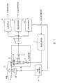
图1为表示根据本发明的一个实施例的光盘装置的结构的方框图;1 is a block diagram showing the structure of an optical disc device according to an embodiment of the present invention;
图2为表示意图1所示的激光控制电路的电路结构的方框图;Fig. 2 is a block diagram showing the circuit structure of the laser control circuit shown in Fig. 1;
图3A-3D为说明在图1所示的光盘装置中执行的多级记录操作的要点的示意图;3A-3D are diagrams illustrating the outline of a multi-level recording operation performed in the optical disc apparatus shown in FIG. 1;
图4A-4D为表示用于在图1所示的光盘装置中的多级记录的激光发射波形的示意图;4A-4D are schematic diagrams showing laser emission waveforms for multilevel recording in the optical disc device shown in FIG. 1;
图5A-5C为说明用于在图1所示的光盘装置中在偏置脉冲中产生良好的调节的处理的波形图;5A-5C are waveform diagrams illustrating a process for producing good adjustment in bias pulses in the optical disc apparatus shown in FIG. 1;
图6为表示激光束根据温度变化的电流-光强度特性的曲线图;Fig. 6 is a graph showing current-light intensity characteristics of a laser beam according to temperature changes;
图7A-7E为说明在偏置能量周期中操作高频调制器(HFM)的时间安排的示意图;7A-7E are schematic diagrams illustrating the timing of operating a high frequency modulator (HFM) during a bias energy cycle;
图8为表示意图1所示的激光控制电路的另一个电路结构的方框图;Fig. 8 is a block diagram showing another circuit structure of the laser control circuit shown in Fig. 1;
图9为用于5级记录的策略(strategy)表的典型格式的图表;Figure 9 is a diagram of a typical format for a strategy table for
图10为表示用于在多级记录中执行第一摆动信号检测过程的电路结构的方框图;10 is a block diagram showing a circuit configuration for performing a first wobble signal detection process in multilevel recording;
图11A-11D为说明在多级记录中具有相同大小的连续记录标记的情况的示意图;11A-11D are diagrams illustrating the case of consecutive recording marks having the same size in multilevel recording;
图12为表示用于在多级记录中执行第二摆动信号检测过程的电路结构的方框图;12 is a block diagram showing a circuit configuration for performing a second wobble signal detection process in multilevel recording;
图13为表示用于在多级记录中执行第三摆动信号检测过程的电路结构的方框图;13 is a block diagram showing a circuit configuration for performing a third wobble signal detection process in multilevel recording;
图14为表示用于在多级记录中执行第四摆动信号检测过程的电路结构的方框图;14 is a block diagram showing a circuit configuration for performing a fourth wobble signal detection process in multilevel recording;
图15为表示用于在多级记录中执行第五摆动信号检测过程的电路结构的方框图;15 is a block diagram showing a circuit configuration for performing a fifth wobble signal detection process in multilevel recording;
图16为表示用于在多级记录中执行第七摆动信号检测过程的电路结构的方框图;16 is a block diagram showing a circuit configuration for performing a seventh wobble signal detection process in multilevel recording;
图17为说明根据本发明的一个实施例的光盘的特性的曲线图;FIG. 17 is a graph illustrating characteristics of an optical disc according to an embodiment of the present invention;
图18为表示四分的(quartered)光接收器的电路结构的方框图;Fig. 18 is a block diagram showing the circuit configuration of a quartered (quartered) optical receiver;
图19为表示用于在多级记录中执行第一伺服信号检测过程的电路结构的方框图;FIG. 19 is a block diagram showing a circuit configuration for performing a first servo signal detection process in multilevel recording;
图20为表示用于在多级记录中执行第二伺服信号检测过程的电路结构的方框图;20 is a block diagram showing a circuit configuration for performing a second servo signal detection process in multilevel recording;
图21为表示用于在多级记录中执行第三伺服信号检测过程的电路结构的方框图;FIG. 21 is a block diagram showing a circuit configuration for performing a third servo signal detection process in multilevel recording;
图22为表示用于在多级记录中执行第四伺服信号检测过程的电路结构的方框图;FIG. 22 is a block diagram showing a circuit configuration for performing a fourth servo signal detection process in multilevel recording;
图23为表示用于在多级记录中执行第五伺服信号检测过程的电路结构的方框图;23 is a block diagram showing a circuit configuration for performing a fifth servo signal detection process in multilevel recording;
图24为表示用于在多级记录中执行第七伺服信号检测过程的电路结构的方框图;FIG. 24 is a block diagram showing a circuit configuration for performing a seventh servo signal detection process in multilevel recording;
图25为表示用于在多级记录中执行第八伺服信号检测过程的电路结构的方框图;25 is a block diagram showing a circuit configuration for performing an eighth servo signal detection process in multilevel recording;
图26A和26B为说明在多级记录中的第八伺服信号检测过程的示意图。26A and 26B are diagrams illustrating the eighth servo signal detection process in multilevel recording.
具体实施方式 Detailed ways
下面,将参考附图说明本发明的优选实施例。Hereinafter, preferred embodiments of the present invention will be described with reference to the accompanying drawings.
图1为表示根据本发明的一个实施例的光盘装置的结构的方框图。FIG. 1 is a block diagram showing the structure of an optical disc device according to an embodiment of the present invention.
该光盘装置为光信息记录装置,例如CD驱动器或DVD驱动器,并且包括一实现光学系统的光拾取器单元1、驱动光拾取器单元1移动并旋转光盘13(也就是,信息记录介质,例如CD或DVD)的马达12、用于控制马达12的旋转的马达驱动电路6,以及其它适当的电子电路。This optical disc device is an optical information recording device, such as a CD drive or a DVD drive, and includes an
光拾取器单元1包括激光光源2、以公知的方式将从激光光源2发射的激光束的光线导引到不同的元件(未示出)的光学元件、将激光束光线在光盘13上聚焦为一个光点的物镜3、和控制透镜的位置以便将射束点导引到期望的位置的致动器4、以及光学接收器(PD:光敏二极管)5。The
光盘装置的各种电路包括根据来自编码器的信号控制激光光源2的激光发射的激光控制电路7。Various circuits of the optical disc device include a
通过配置激光束使其包括一具有预定的高光强度的写能量周期、一具有比写能量周期的预定的光强度低的光强度的低能量周期、具有比写能量周期的光强度低且比低能量周期的光强度高地光强度的间隔能量周期、和具有比间隔能量周期的光强度低但比低能量周期的光强度高的光强度的偏置能量周期,激光控制电路7具有管理每个标记在形成在光记录介质的区域上的单元上的记录的功能。By configuring the laser beam to include a write energy period with a predetermined high light intensity, a low energy period with a light intensity lower than the predetermined light intensity of the write energy period, a light intensity lower than the write energy period and lower than the The light intensity of the energy period is high, the interval energy period of the light intensity, and the bias energy period with the light intensity lower than the light intensity of the interval energy period but higher than the light intensity of the low energy period, and the
图2为表示激光控制电路7的典型内部电路结构的方框图。根据该图,激光控制电路7包括控制单元20、策略(strategy)产生单元21和激光驱动单元22。FIG. 2 is a block diagram showing a typical internal circuit configuration of the
从外部源传来的作为记录数据的用户数据在由CPU(未示出)控制的编码电路(未示出)处被转换为多级信息。由编码电路获得的多级信息然后被传送给激光器控制电路7的控制单元20。其它信号,例如表示记录/播放状态的信号和表示与多级信息同步的单元频率的时钟信号也被传送给了控制单元20。User data transmitted from an external source as recording data is converted into multi-level information at an encoding circuit (not shown) controlled by a CPU (not shown). The multilevel information obtained by the encoding circuit is then transmitted to the
在图2的例子中,信号被从编码电路供给;然而,信号也可以由其它不同的电路供给。例如,播放信号/记录信号可从CPU传送,而时钟信号可从时钟产生电路传送。In the example of FIG. 2, the signal is supplied from the encoding circuit; however, the signal may also be supplied by other different circuits. For example, a playback signal/recording signal may be transmitted from a CPU, and a clock signal may be transmitted from a clock generation circuit.
例如,控制电路20根据接收的信号设置策略产生电路21和激光器驱动单元22。For example, the
例如,根据控制单元20的输出信号和时钟信号,策略产生单元21根据写能量周期、低能量周、偏置能量周期和间隔能量周期的时间控制产生一脉冲信号,在所述这些能量周期中激光束分别以写能量Pw、低能量Pof、偏置能量Pb和间隔能量Ps进行辐射。For example, according to the output signal and the clock signal of the
激光器驱动单元22,例如根据延迟播放信号/延迟记录信号(通过对播放信号/记录信号延迟策略产生单元21的处理时间而获得)、来自策略产生单元21的表示写能量周期、低能量周期、偏置能量周期和间隔能量周期的时间控制的脉冲信号、和为每个脉冲指定的强度信号来确定用于激光源2的驱动电流,在所述这些能量周期中激光束分别以写能量Pw、低能量Pof、偏置能量Pb和间隔能量Ps进行发射。The
换言之,控制单元20、策略产生单元21和激光器驱动单元22具有这样的功能:输入表示单元频率的时钟信号和与每个单元对应的多级信息,和根据输入的时钟信号和多级信息为每个单元确定一激光束发射波形。In other words, the
另外,由于激光源2的当前光的输出特性根据温度存在很大的不同,所以激光器驱动单元22具有用于检测输出光强度和使输出稳定的输出控制功能。光强度检测可由激光源2中安装的光学接收器5执行,或者相反,用于检测光强度的光学系统可单独设置。此外,激光器驱动单元22可具有用于减少激光源2的输出噪音的高频叠加功能。In addition, since the output characteristics of the current light of the
其它电路包括I/V(电流/电压)电路8,用于对光接收器5处接收到的来自光盘13的反射信号执行电流到电压的变换,其结果经变换的信号被传送给若干不同的检测电路。Other circuits include an I/V (current/voltage) circuit 8 for performing a current-to-voltage conversion of the reflected signal received at the
I/V电路8对应于第一级电路,并且这里,分别为播放和记录设置了合适的变换效率比(增益)。The I/V circuit 8 corresponds to a first-stage circuit, and here, appropriate conversion efficiency ratios (gains) are set for playback and recording, respectively.
RF检测电路9提取记录在光盘13上的多级信息分量,并将检测到的组分发送给解码电路(未示出)。接着,解码器将多级信息分量转变为用户数据。The
摆动检测电路10从表示来自光接收器5的各个部件的输出之间的差的推挽信号提取包含在形成在光盘上的轨迹中的摆动信号分量,光接收器5的各部分是由沿光盘13上的轨迹切线方向延伸的分割线分割的,并且摆动检测电路10将所提取的分量发送给地址检测电路(未示出)和时钟检测电路(未示出),例如,使得摆动信号能被用于管理光盘13的绝对定位、产生与介质旋转同步的时钟信号、和控制介质旋转。适于摆动信号检测的时间控制信号主要由激光器控制电路7提供。The
伺服检测电路11提取激光射束点的位置信息并向马达驱动电路6发送指令,马达驱动电路6用于将射束点照射至期望的位置并驱动光拾取器单元1和致动器4移动。The
图3A-3D为说明在图1的光盘装置中执行的多级记录操作的要点的示意图。3A-3D are diagrams illustrating the outline of a multi-level recording operation performed in the optical disc device of FIG. 1 .
如图3A所示,具有实质上相同的(virtually uniform)长度的虚单元被定义在于光盘13上形成的轨迹上,且在每个虚单元的中心处形成一个记录标记。作为例子,在该图中,电平3(L3)、电平4(L4)和电平1(L1)的标记被分别记录在三个连续的虚单元上。在图3B中,示出了记录标记的典型形状。As shown in FIG. 3A, virtual cells having a virtually uniform length are defined on tracks formed on the
图3C表示用于记录标记的激光发射波形的例子。激光发射波形包括以写能量Pw辐射的写能量周期、以低能量Pof照射的低能量周期、以偏置能量Pb照射的偏置能量周期和以间隔能量Ps进行辐射的间隔能量周期。Fig. 3C shows an example of laser emission waveforms for recording marks. The laser emission waveform includes a write energy period irradiated with write energy Pw, a low energy period irradiated with low energy Pof, a bias energy period irradiated with bias energy Pb, and a spaced energy period irradiated with spaced energy Ps.
图3D表示在播放期间从每个单元的反射光获得的播放信号的例子。通过判定播放信号的信号强度电平,可以估算出记录在每个单元上的标记的面积且根据每个单元的面积能够重放记录的信息。Fig. 3D shows an example of a playback signal obtained from the reflected light of each cell during playback. By determining the signal strength level of the playback signal, the area of the mark recorded on each cell can be estimated and the recorded information can be reproduced based on the area of each cell.
例如,如果具有三个不同面积(L1-L3)的三个不同的记录标记能被记录在虚单元上并能重放,这意味着能在每个单元中存储四个电平或两个比特的信息(即,没有标记、标记L1、标记L2、和标记L3)。另一方面,如果能鉴别出七个不同的记录标记(L1-L7),那么在每个单元中可存储八个电平或三个比特的信息。For example, if three different recording marks with three different areas (L1-L3) can be recorded on dummy cells and reproduced, this means that four levels or two bits can be stored in each cell (ie, no flag, flag L1, flag L2, and flag L3). On the other hand, if seven different recording marks (L1-L7) can be identified, eight levels or three bits of information can be stored in each cell.
通过在不超出光学分辨率的区域中建立记录标记的面积与播放信号的幅度之间的固定的关系可实现多级信息记录。Multilevel information recording can be achieved by establishing a fixed relationship between the area of the recording mark and the amplitude of the playback signal in an area not exceeding the optical resolution.
随着单元长度变短,由于每个电平之间的差变得越来越小,则越来越难于鉴别记录在虚单元上的多级信息的电平。As the cell length becomes shorter, it becomes more and more difficult to discriminate the level of the multi-level information recorded on the dummy cell because the difference between each level becomes smaller.
相反,当单元长度增加到超出了光学分辨率的程度时,信号幅度将是饱和的且因此将不可能鉴别多级信息。由于上面解释的原因,需要或有必要采取一些限制来设置光点直径和单元长度(单元宽度)之间的关系。Conversely, when the cell length is increased beyond the optical resolution, the signal amplitude will be saturated and thus it will be impossible to discriminate multi-level information. For the reasons explained above, it is necessary or necessary to take some restrictions to set the relationship between the spot diameter and the cell length (cell width).
另外,注意虚单元不必在整个介质上以绝对等长度的方式进行定义。相反地,虚单元的长度可发生少许的变化,只要变化的长度在能使多级信息呈现适当的区别的范围内。Also, note that virtual elements do not have to be defined with absolutely equal length over the entire medium. On the contrary, the length of the dummy cell can be changed slightly, as long as the length of the change is within the range that enables the multi-level information to exhibit appropriate distinction.
因此,例如,在光盘13的记录区域在径向上被分割以形成若干区并且在每个区上使用了以固定介质转动角速度的CAV格式的情况下,单元长度随着单元朝向每个区的外周边移动而逐渐变长。然而,通过增加区的数量,在内周边侧的单元长度和在该区内的外周边侧的单元长度之间的差可被最小化并且能精确地鉴别出多级信息。Therefore, for example, in the case where the recording area of the
图4A-4D为表示用于在图1所示的光盘装置中记录多级信息的激光发射波形的示意图。4A-4D are diagrams showing laser emission waveforms for recording multi-level information in the optical disc device shown in FIG. 1. Referring to FIG.
在该例子中,用于在虚单元上记录标记的激光束发射波形能以四个电平(L1-L4)记录信息。如图所示,每个用于记录标记的激光发射波形包括以被设定为能够表示信息的高光强度的写能量Pw辐射的写能量周期、以设定为比写能量Pw的光强度低的能量Pof照射的低能量周期、在低能量周期之后输出的并以设定为比间隔能量Ps低但比低能量Pof高的光强度的偏置能量Pb照射的偏置能量周期、和能够隔开信息并且以设定为比写能量Pw低但比低能量Pof高的光强度的间隔能量Ps进行辐射的间隔能量周期。然而,注意用于在电平L1处记录标记的激光发射波形不包括偏置能量周期。In this example, the laser beam emission waveform for recording marks on the dummy cells can record information at four levels (L1-L4). As shown in the figure, each laser emission waveform for recording a mark includes a write energy period irradiated with a write energy Pw set to a high light intensity capable of expressing information, a light intensity set to be lower than the write energy Pw. The low energy period of the energy Pof irradiation, the bias energy period output after the low energy period and irradiated with the bias energy Pb of light intensity set to be lower than the interval energy Ps but higher than the low energy Pof, and the information and is radiated for interval energy periods at an interval energy Ps set to a light intensity lower than the write energy Pw but higher than the low energy Pof. Note, however, that the laser shot waveform for recording marks at level L1 does not include a bias energy period.
同时要注意,在附图中,以阴影线填充的椭圆图形为表示记录标记相对单元的定位的虚单元;因此,这些图形不表示记录标记的实际形状。Also note that in the drawings, hatched elliptical figures are imaginary units representing the positioning of the recording marks relative to the units; therefore, these figures do not represent the actual shape of the recording marks.
在记录标记时,写能量周期、低能量周期、和偏置能量周期的发射时间根据标记的电平被从虚单元的中心位置偏移,以便在虚单元的中心处形成标记。When recording a mark, the emission times of the write energy period, the low energy period, and the bias energy period are shifted from the center position of the dummy cell according to the level of the mark to form a mark at the center of the dummy cell.
下面,将介绍在根据本发明的实施例的光盘装置中执行的处理。Next, the processing performed in the optical disc device according to the embodiment of the present invention will be described.
在将标记记录到单元上时,激光器控制电路7辐射具有写能量Pw的激光束,写能量Pw被设定为在写能量周期中具有预定高的光强度。例如,激光器控制电路7可以14mW的光强度照射激光束,以使光盘的记录层熔化。然后,在低能量周期中,照射具有低能量Pof的激光束,低能量Pof被设定为具有比写能量Pw低的光强度。在该周期中,光发射非常微弱并且几乎没有发射任何光。例如,可以以0-0.5mW的光强度辐射激光束,以使光盘的记录层被快速冷却。从而,形成了标记的前沿。When recording a mark onto a cell, the
在常规的光盘装置中,辐射相应于低能量周期的激光束直到形成所要求的标记长度,然后辐射具有能擦除标记的光强度的对应于间隔能量周期的激光束。例如,在间隔能量周期中可以7mW的光强度辐射激光束以形成记录标记的后沿。In a conventional optical disk device, a laser beam corresponding to a low energy period is irradiated until a desired mark length is formed, and then a laser beam corresponding to an alternate energy period is irradiated with a light intensity capable of erasing the mark. For example, a laser beam may be irradiated at a light intensity of 7 mW in interval energy periods to form trailing edges of recording marks.
然而,在本实施例中,在低能量周期之后提供有偏置能量周期,在该周期中具有偏置能量Pb的激光束被设定为具有比间隔能量Ps低但比低能量Pof高的光强度(即,Ps>Pb>Pof)。例如,对于偏置能量周期可以使用具有1-2mW的光强度的激光束。However, in the present embodiment, after the low power period, there is provided a bias power period in which the laser beam having the bias power Pb is set to have light lower than the interval power Ps but higher than the low power Pof Intensity (ie, Ps>Pb>Pof). For example, a laser beam with a light intensity of 1-2 mW may be used for the bias energy period.
对应于偏置能量周期的激光束的光强度Pb优选地在这样一个电平范围内:在该范围内信号分量可被保护免受在用于记录的第一级电路增益(其低于用于播放的增益)中的噪音的干扰,同时可保持记录特性。因此,记录层在写能量周期之后的低能量期间被冷却,以形成标记,并且即使在偏置能量周期期间辐射了具有比重放能量Pr高的光强度的激光束,标记也不会老化(degraded)。另外,注意在上面的说明中给出的特定的光强度值仅仅是例子,并且这些值根据介质的层特性可发生变化。The light intensity Pb of the laser beam corresponding to the bias energy cycle is preferably within a level range within which the signal component can be protected from gain in the first-stage circuit for recording (which is lower than that for playback gain) while maintaining recording characteristics. Therefore, the recording layer is cooled during the low energy period after the writing energy period to form marks, and even if a laser beam having a light intensity higher than the reproducing energy Pr is irradiated during the bias energy period, the marks are not degraded. ). Also, note that the specific light intensity values given in the above description are examples only, and that these values may vary depending on the layer properties of the medium.
在常规的光盘装置的激光束发射波形中,当连续形成短标记时,信号能在间隔能量周期过程中检测出来,并且能获得满足要求的记录质量。然而,当连续形成长标记时,例如在电平4(L4)处的标记,在其间不能执行信号检测的写能量周期和低能量周期占用了激光束辐射时间的大部分,并且在其间可以进行信号检测的间隔能量周期是非常短的以至记录质量下降了。In the laser beam emission waveform of a conventional optical disc device, when short marks are continuously formed, signals can be detected during interval energy periods, and satisfactory recording quality can be obtained. However, when long marks such as marks at level 4 (L4) are continuously formed, the write energy period and the low energy period during which signal detection cannot be performed occupy most of the laser beam irradiation time, and during which signal detection cannot be performed. The energy period between signal detections is so short that the recording quality deteriorates.
然而,根据本实施例,能在偏置能量周期期间提取信号分量,使得即使连续形成长标记也不会降低记录质量。同时,根据上面的记录处理,偏置能量周期被插在低能量周期之后;然而,偏置能量周期的时间安排不局限于这样的布置,而是偏置能量周期可以插入到用于记录标记的激光束辐射周期过程中的任何时刻。However, according to the present embodiment, signal components can be extracted during the bias energy period, so that the recording quality is not lowered even if long marks are continuously formed. Meanwhile, according to the recording process above, the bias power period is inserted after the low power period; however, the timing of the bias power period is not limited to such an arrangement, but the bias power period may be inserted into the Any moment during the laser beam irradiation cycle.
通过在用于标记形成的激光束发射波形中插入具有介于低能量部分和间隔能量部分的光强度之间的光强度的偏置能量部分,能够防止记录质量的下降,即使在连续记录长标记期间也能检测出不同的检测信号,并且能使激光束的输出控制稳定化。By inserting a bias energy portion having a light intensity between those of the low energy portion and the space energy portion in the laser beam emission waveform for mark formation, it is possible to prevent degradation of recording quality even when long marks are continuously recorded During this period, different detection signals can be detected, and the output control of the laser beam can be stabilized.
下面,将介绍在本实施例的光盘装置中执行的进一步的处理。Next, further processing performed in the optical disc device of this embodiment will be described.
为了在光盘上以正确的尺寸精确形成记录标记,可为每次记录调节在偏置能量周期中的激光束发射时间。In order to accurately form recording marks with correct dimensions on the optical disc, the laser beam emission time in the bias energy period can be adjusted for each recording.
所述“以正确的尺寸精确的形成记录标记”不是意味着记录标记的物理面积必须对应于多级值(多级信息的电平),而是,记录面积使记录的多级信息在播放信号中能被容易地鉴别出。Said "accurately forming recording marks with correct size" does not mean that the physical area of the recording marks must correspond to the multilevel value (the level of the multilevel information), but the recording area makes the recorded multilevel information appear in the playback signal can be easily identified.
在多级信息记录中,由于形成了比光学分辨率小的标记,所以用于记录标记的初始信息所需要的写能量周期的时间宽度通常是固定的,而与多级信息无关。因此,用于确定表示多级信息的标记区域的主要因素为“低能量周期的时间宽度+偏置能量周期的时间宽度”。In multilevel information recording, since marks smaller than the optical resolution are formed, the time width of a write energy period required for recording initial information of the mark is generally fixed regardless of the multilevel information. Therefore, the main factor for determining the marking area representing multi-level information is "the time width of the low energy period + the time width of the bias energy period".
对于每组多级信息用于冷却光盘的记录层所需要的低能量周期的时间宽度是通过记录层的特性确定的,并且因此是固定的,而与多级信息无关。The time width of the low energy periods required for cooling the recording layer of the optical disc for each set of multilevel information is determined by the properties of the recording layer and is therefore fixed regardless of the multilevel information.
在本实施例中,通过设置偏置能量周期的时间宽度使其对应于与被记录的多级信息的电平(多级值)相称的时间部分和根据每组多级信息被调节的时间部分的和,激光器控制电路7调节用于每组多级信息的偏置能量周期的时间宽度。In this embodiment, by setting the time width of the bias energy cycle so that it corresponds to the time part commensurate with the level (multi-level value) of the recorded multi-level information and the time part adjusted according to each group of multi-level information and, the
根据每组被记录的多级信息调节偏置能量周期的时间宽度的处理依赖于这样的事实:在每个单元上形成有具有“多级值-1”的面积的分布的标记,使得偏置能量周期的时间宽度与被记录的多级信息的电平近似相称。The process of adjusting the time width of the bias energy period according to each set of recorded multi-level information relies on the fact that a mark with a distribution of the area of "multi-level value -1" is formed on each cell such that the bias The time width of the energy period is approximately proportional to the level of the recorded multi-level information.
图5A-5C为说明在本实施例的光盘装置中调节偏置能量周期的时间宽度的处理的示意图。5A-5C are diagrams illustrating the process of adjusting the time width of the bias energy cycle in the optical disc device of this embodiment.
图5A示出表示单元频率的单元时钟的波形(时钟信号);而图5B示出具有n倍的单元时钟频率的周期的n倍时钟信号(n为整数)的波形。如图5C所示,偏置脉冲时间根据被记录的多级信息的电平以时间宽度Tx为单位成比例地变化。即,用于记录标记L2的偏置能量周期的时间宽度比用于记录标记L1的偏置能量周期的时间宽度长时间宽度Tx,用于记录标记L 3的偏置能量周期的时间宽度比用于记录标记L1的偏置能量周期的时间宽度长2Tx(时间宽度Tx的两倍)。FIG. 5A shows a waveform (clock signal) of a unit clock representing a unit frequency; while FIG. 5B shows a waveform of an n-fold clock signal (n is an integer) having a period n times the unit clock frequency. As shown in FIG. 5C, the bias pulse time is proportionally changed in units of time width Tx according to the level of multilevel information to be recorded. That is, the time width of the bias energy cycle for the recording mark L2 is longer than the time width Tx of the bias energy cycle for the recording mark L1, and the time width of the bias energy cycle for the recording mark L3 is longer than the time width Tx of the bias energy cycle for the recording mark L3 The time width of the bias energy cycle of the recording mark L1 is 2Tx longer (twice the time width Tx).
然而,光记录介质的记录层不必具有线性特性,且用于获得期望的播放信号电平所需要的时间根据前述的和后来的单元的多级值变化。因此,在为每级多级信息提供的时间宽度Ty内最好对偏置能量周期的时间宽度进行微调,如图5C所示。激光控制电路7通过根据计算式:Tb=(a-1)Tx+Ty(Tb:偏置能量周期的时间宽度;a:多级值)进行微调来确定偏置能量周期的时间宽度。However, the recording layer of the optical recording medium does not necessarily have a linear characteristic, and the time required for obtaining a desired playback signal level varies depending on the multilevel value of the preceding and subsequent units. Therefore, it is preferable to fine-tune the time width of the bias energy period within the time width Ty provided for each level of multi-level information, as shown in FIG. 5C . The
因此,用于电平1的偏置能量周期Tb的时间宽度为Ty,用于电平2的偏置能量周期Tb的时间宽度为“Tx+Ty”,用于电平3的偏置能量周期T的时间宽度为“2Tx+Ty”,而用于电平4的偏置能量周期Tb的时间宽度为“3Tx+Ty”。Therefore, the time width of the bias energy cycle Tb for
注意,在调节偏置能量周期的时间宽度中未使用与多级信息的电平相称的时间部分的情况下,在管理用于确定对于多级信息的偏置能量周期的时间宽度的参数中,就最小光学分辨率来说,必须考虑整个单元。另一方面,在与多级值相称的加上/减去时间宽度单元的情况下,根据被记录的信息的多级值和相应的良好调节部分而不是整个单元对用于确定偏置能量周期的时间宽度的参数进行管理,从而能够大大减少激光控制电路7的处理负荷。Note that in the case where a time portion commensurate with the level of the multilevel information is not used in adjusting the time width of the bias energy period, in managing the parameters for determining the time width of the bias energy period for the multilevel information, For minimum optical resolution, the entire unit must be considered. On the other hand, in the case of plus/minus time-width cells commensurate with multi-level values, the multi-level values and corresponding well-regulated fractions of the recorded information rather than the entire cell pair are used to determine the bias energy period By managing the parameters of the time width, the processing load on the
根据该实施例,由于偏置能量周期的时间宽度是由根据多级信息的电平(多级值)而被加上/减去的成比例的时间部分和用于每次记录的良好调节部分组成,所以,能够简化脉冲宽度的设置和每个能量部分的时间控制。According to this embodiment, since the time width of the bias energy period is a proportional time portion that is added/subtracted according to the level of the multi-level information (multi-level value) and a well-adjusted portion for each recording Composition, therefore, can simplify the setting of the pulse width and the timing control of each energy part.
下面,介绍本发明的另一个实施例,其中激光控制电路7在多级信息满足预定的条件时输出偏置能量周期。Next, another embodiment of the present invention will be introduced, in which the
如图4A所示,当通过辐射相应于针对最小所需时间周期的写能量周期和低能量周期的激光束而形成标记时,即,当形成标记L1时,不辐射用于偏置能量周期的激光束。同时,当记录信息为表示空格(没有标记)的L0时,激光发射波形由间隔能量周期组成,并且因此不产生用于偏置能量周期的激光束。另外,在偏置能量周期是非常短的(例如,标记L2)以至不能有效地检测到信号分量的情况下,可优选地消除用于偏置能量周期的激光束发射。As shown in FIG. 4A, when a mark is formed by irradiating a laser beam corresponding to a write energy period and a low energy period for the minimum required time period, that is, when forming a mark L1, the laser beam for the bias energy period is not irradiated. Laser beam. Meanwhile, when the recording information is L0 representing a space (no mark), the laser emission waveform consists of interval energy periods, and thus no laser beam for offset energy periods is generated. Also, where the bias energy period is so short (eg, mark L2) that the signal component cannot be effectively detected, it may be preferable to eliminate laser beam emission for the bias energy period.
做出这样的设置来防止由于光接收器中的限制和电路的响应速度而引起的信号分量的恶化,并用于消除来自噪音的不期望的影响,所述噪音是在短周期期间对信号分量进行取样时产生的。Such a setting is made to prevent deterioration of the signal component due to limitations in the optical receiver and response speed of the circuit, and to eliminate undesired influence from noise that acts on the signal component during a short period generated during sampling.
因此,在多级信息满足特定的条件时,通过输出用于偏置能量周期的激光束,在无法保证精确信号检测的充足时间宽度时,能够防止用于偏置能量周期的激光束发射。结果,在偏置能量周期过程中能够消除在信号检测中存在的误差并且能检测出高质量信号。Therefore, by outputting the laser beam for the offset energy period when the multilevel information satisfies a specific condition, emission of the laser beam for the offset energy period can be prevented when a sufficient time width for accurate signal detection cannot be ensured. As a result, errors existing in signal detection can be eliminated and high-quality signals can be detected during the bias energy period.
下面,介绍本发明的另一个实施例,其中激光控制电路7控制用于偏置能量周期的激光束的光强度(Pb)使其高于在重放多级信息过程中辐射的激光束的光强度(Pr)。Next, another embodiment of the present invention is introduced, in which the
偏置能量Pb优选地被设置为在电平范围中的最大电平,在所述范围中,对于信号检测能够得到足够的记录质量。重放能量Pr被设置为这样一个电平:此时即使重放操作已经执行了一个很长的时间,也能防止记录的数据老化。例如,可将重放能量设置为0.7mW。换句话说,重放能量被优选地设置为低于记录层可被热老化的电平,但偏置能量Pb可比重放能量Pr高,因为偏置能量周期在记录过程中表现为短周期。The bias energy Pb is preferably set to the maximum level in the range of levels in which sufficient recording quality can be obtained for signal detection. The playback power Pr is set to a level at which aging of the recorded data can be prevented even if the playback operation has been performed for a long time. For example, playback energy can be set to 0.7mW. In other words, the playback energy is preferably set lower than the level at which the recording layer can be thermally aged, but the bias energy Pb can be higher than the playback energy Pr because the bias energy period appears as a short period during recording.
另外,当偏置能量Pb被设定为低于重放能量Pr,并且第一级电路增益比在重放时的低时,可能难于获得期望的信号质量。In addition, when the bias energy Pb is set lower than the reproduction energy Pr, and the first-stage circuit gain is lower than that at the time of reproduction, it may be difficult to obtain a desired signal quality.
因此,对应于偏置能量Pb的光强度Pb优选地被设置为比重放能量Pr高的光强度,以便从偏置能量周期能获得预期的效果。Therefore, the light intensity Pb corresponding to the bias energy Pb is preferably set to a higher light intensity than the playback energy Pr so that a desired effect can be obtained from the bias energy period.
通过将偏置能量周期的偏置能量Pb设置为高于在播放过程中的光强度,即使用于记录的最佳电路增益是低的,也能防止在偏置能量周期期间检测的信号受到噪音的干扰。By setting the bias energy Pb of the bias energy period higher than the light intensity during playback, even if the optimum circuit gain for recording is low, the signal detected during the bias energy period can be prevented from being noisy interference.
下面,将介绍本发明的进一步的实施例,尤其是用于可重写型介质,例如相变介质,其中激光控制电路7将间隔能量周期的光强度设置为能够擦除标记的电平。In the following, a further embodiment of the present invention will be described, especially for rewritable media, such as phase change media, in which the
在可重写型介质中,具有用于形成记录标记的激光束发射波形的低光强度的低能量周期被延长,而且,同时,可重写型介质的反射率是低的,使得在低能量周期中不能执行信号检测。然而根据本发明,通过在激光束发射波形中设置偏置能量周期,可提高信号检测性能。In the rewritable type medium, the low energy period with the low light intensity of the laser beam emission waveform for forming the recording mark is extended, and, at the same time, the reflectivity of the rewritable type medium is low, so that at low energy Signal detection cannot be performed during the cycle. According to the present invention, however, signal detection performance can be improved by setting a bias energy cycle in the laser beam emission waveform.
因此,根据本实施例,即使在由于介质的低反射率和低能量周期的低光强度而使得信号分量的检测非常困难的情况下使用了可重写型介质,在偏置能量周期期间也能获得改善的信号检测性能。Therefore, according to the present embodiment, even when a rewritable type medium is used where the detection of signal components is very difficult due to the low reflectance of the medium and the low light intensity of the low power period, during the bias power period Get improved signal detection performance.
下面,将介绍本发明的进一步的实施例,其中激光控制电路7检测用于偏置能量周期和间隔能量周期的激光束的光强度并且根据该检测得的光强度补偿用于写能量周期的光强度,以便保持激光束的输出强度的精度。Next, a further embodiment of the present invention will be introduced, wherein the
图6为表示激光束根据温度变化的电流-光强度特性的曲线图。Fig. 6 is a graph showing current-light intensity characteristics of a laser beam according to temperature changes.
激光束的输出特性根据温度存在很大的不同。如图所示,当温度(T)为50℃时随电流值(电流的量)变化的光强度灵敏度比在温度为25℃时的低。The output characteristics of the laser beam vary greatly depending on the temperature. As shown in the figure, the light intensity sensitivity to the current value (amount of current) is lower when the temperature (T) is 50°C than when the temperature is 25°C.
因此,例如,在温度25℃处,当驱动电流被设定为能够输出对应于用于间隔能量周期的间隔能量Ps的光强度的电流值Is时,在温度50℃处的输出光强度Ps被减小到约2/3,如图中在T=50℃的虚线上由圆圈○表示的。因此,通过检测输出激光束的间隔能量Ps并控制电流值使得光强度被恒定的保持在一个相同的水平上,可获得对于50℃的相应的电流值Is’,如在50℃的虚线上由方块□所表示的。Therefore, for example, at a temperature of 25° C., when the driving current is set to a current value Is capable of outputting a light intensity corresponding to the interval energy Ps for the interval energy cycle, the output light intensity Ps at a temperature of 50° C. is Reduced to about 2/3, as indicated by circles on the dotted line at T=50°C in the figure. Therefore, by detecting the interval energy Ps of the output laser beam and controlling the current value so that the light intensity is kept constant at the same level, the corresponding current value Is' for 50°C can be obtained, as shown on the dotted line at 50°C by Indicated by square □.
然而,控制对应于用于写能量周期的写能量Pw的光强度是非常困难的。这是因为写能量Pw的写能量部分的宽度是短的,因此难于精确检测光强度。However, it is very difficult to control the light intensity corresponding to the write energy Pw for the write energy period. This is because the width of the write energy portion of the write energy Pw is short, so it is difficult to accurately detect the light intensity.
例如,当间隔能量Ps和写能量Pw在温度25℃时的电流差(Iw-Is)被加到电流值Is’(Is’+Iw-Is)时,结果得到的电流值Iw″在温度50℃处不会输出写能量Pw,相反输出较低的写能量Pw″,如50℃的虚线上由三角△标出的,该作用是在灵敏度上存在差异的结果。For example, when the current difference (Iw-Is) between the space energy Ps and the write energy Pw at a temperature of 25°C is added to the current value Is' (Is'+Iw-Is), the resulting current value Iw" at a temperature of 50 No write energy Pw is output at °C, but a lower write energy Pw″ is output instead, as marked by a triangle △ on the dotted line at 50 °C. This effect is the result of the difference in sensitivity.
因此,优选地,为了获得光强度灵敏度对另一个能量部分的光强度进行检测,并使用根据该获得的灵敏度计算得到的电流值。在根据本发明的光盘装置中,使用了偏置能量周期的光强度。Therefore, preferably, the light intensity of another energy portion is detected in order to obtain the light intensity sensitivity, and the current value calculated from the obtained sensitivity is used. In the optical disc device according to the present invention, the light intensity of the bias energy period is used.
特定地,激光控制电路7执行下述的运算处理。Specifically, the
首先,在执行电流控制以便将间隔能量Ps保持在一个固定的水平的同时,检测偏置能量周期的偏置能量Pb和与之相应的在50℃时的电流值Ib’。然后,根据间隔能量Ps、及其相应的电流值Is′、偏置能量Pb、和它相应的电流值Ib’,计算灵敏度(Is’-Ib’)/(Ps-Pb),并且从等式Iw’=Is’+(Pw-Ps)×(Is’-Ib’)/(Ps-Pb)得到的电流值Iw’被用作输出写功率Pw的驱动电流。First, the bias energy Pb of the bias energy period and the current value Ib' at 50°C corresponding thereto are detected while current control is performed so as to maintain the space energy Ps at a fixed level. Then, the sensitivity (Is'-Ib')/(Ps-Pb) is calculated from the interval energy Ps, and its corresponding current value Is', the bias energy Pb, and its corresponding current value Ib', and from the equation The current value Iw' obtained by Iw'=Is'+(Pw-Ps)*(Is'-Ib')/(Ps-Pb) is used as the driving current for outputting the write power Pw.
在常规的光盘装置中,除了间隔能量周期外没有合适的能量部分可用于检测光强度,并且虽然低能量周期对于光强度检测是足够长的,但该能量部分的光强度是非常低的使得不能保证精确检测。In conventional optical disk devices, no suitable energy portion is available for detecting light intensity except for interval energy periods, and although the low energy period is long enough for light intensity detection, the light intensity of this energy portion is so low that it cannot Guaranteed accurate detection.
因此,如果在上述的运算中使用了低能量Pof来计算写能量Pw,那么电流值相对于温度变化存在的差是最小化的,如图所示,使得在灵敏度变化检测中可以很容易地产生误差。换言之,光强度越高,越容易检测温度变化,并且越不可能产生误差。Therefore, if the low-energy Pof is used to calculate the write energy Pw in the above calculation, the difference in the current value with respect to the temperature change is minimized, as shown in the figure, so that it can be easily generated in the sensitivity change detection error. In other words, the higher the light intensity, the easier it is to detect a temperature change and the less likely it is to make an error.
然而,根据本实施例,由于偏置能量周期被提供用于记录多级信息,所以可执行激光束控制,此时,通过检测用于间隔能量周期和偏置能量周期的激光束光强度可获得灵敏度,并且根据灵敏度检测出用于不适于光强度检测的能量部分,即,写能量周期的电流值。However, according to the present embodiment, since the bias energy period is provided for recording multi-level information, laser beam control can be performed, at this time, by detecting the laser beam light intensity for the interval energy period and the bias energy period, it can be obtained Sensitivity, and according to the sensitivity, the energy portion not suitable for light intensity detection, that is, the current value of the writing energy cycle is detected.
在不使用上述运算的情况下,记录被周期性地暂停以从记录区域离开,并且检测和补偿每个能量部分的电流-光特性。Without using the above operations, the recording is periodically paused to leave the recording area, and the current-optical characteristics of each energy fraction are detected and compensated.
因此,通过检测用于间隔能量周期和偏置能量周期的激光束强度,并根据该检测的光强度补偿写能量周期,当在标记记录过程中由于温度的变化发生了激光特性的变化时,信息记录处理不必暂停以纠正激光发射特性。因此,每个能量部分的光强度被维持在最佳水平,使得能够获得高记录质量。Therefore, by detecting the intensity of the laser beam for the spacer energy period and the bias energy period, and compensating the write energy period based on the detected light intensity, when a change in the characteristics of the laser occurs due to a change in temperature during mark recording, the information Recording processing does not have to be paused to correct laser emission characteristics. Therefore, the light intensity of each energy portion is maintained at an optimum level, enabling high recording quality to be obtained.
下面,将介绍本发明的进一步的实施例,其中在偏置能量周期中对高频调制器进行操作。In the following, a further embodiment of the invention will be described, in which the high frequency modulator is operated in a bias energy period.
在通过激光束发射记录多级信息过程中,由于来自返回光(反射光)的影响,在激光束输出中产生了不稳定性,并且不稳定性在低输出中尤其明显。为了抵制该影响,使用了高频调制器(FHM)。在以低输出进行播放的过程中使用高频调制器以高频发射激光束以稳定输出,并且该调制器能被开启/关闭。In recording multi-level information by laser beam emission, instability occurs in laser beam output due to influence from returning light (reflected light), and the instability is particularly noticeable at low output. To counteract this effect, a high frequency modulator (FHM) is used. A high-frequency modulator is used to emit a laser beam at a high frequency to stabilize output during playback at a low output, and the modulator can be turned on/off.
通常,在记录过程中的激光束输出为高,并且因此,不会使用用于消除来自返回光的影响的高频调制器。Generally, the laser beam output during recording is high, and therefore, a high-frequency modulator for canceling influence from returning light is not used.
然而,在多级记录的情况下,在记录期间,在具有低输出的偏置能量周期中检测信号分量,从而产生激光束的不稳定输出的问题。因此,最好还是在偏置能量周期过程中优先操作高频调制器,以使激光束输出稳定化。However, in the case of multilevel recording, during recording, a signal component is detected in a bias energy period with a low output, thereby causing a problem of unstable output of the laser beam. Therefore, it is also preferable to operate the high frequency modulator preferentially during the bias energy cycle to stabilize the laser beam output.
根据本实施例,激光控制电路7控制高频调制器以在偏置能量周期过程中进行操作。According to the present embodiment, the
图7A-7E为说明在偏置能量周期中操作高频调制器(HFM)的时间安排的示意图。7A-7E are schematic diagrams illustrating the timing of operating a high frequency modulator (HFM) during a bias energy period.
图7A表示虚单元(图中的标记*表示数字1-4);图7B表示虚记录标记(将被记录的标记);图7C表示在播放和记录过程中的能量波形;图7D表示在偏置能量周期过程中对高频调制器进行操作时的激光束发射波形;而图7E表示用于操作高频调制器的开/关的时间控制信号的波形。Fig. 7 A represents dummy unit (mark * in the figure represents numeral 1-4); Fig. 7 B represents dummy recording mark (the mark that will be recorded); Fig. 7 C represents the energy waveform in playing and recording process; Fig. 7 D represents The laser beam emission waveform when the high frequency modulator is operated during the set energy cycle; and FIG. 7E shows the waveform of the time control signal for operating the high frequency modulator on/off.
根据图7E所示的时间控制信号,激光控制电路7控制高频调制器在偏置能量周期过程中进行操作。According to the time control signal shown in FIG. 7E , the
通过在偏置能量周期过程中操作高频调制器,在光强度电平为低的偏置能量周期过程中可使激光束输出稳定化,并能实现高质量信号检测。注意高频调制器也可以在间隔能量周期中进行操作。By operating the high-frequency modulator during the bias energy period, the laser beam output can be stabilized during the bias energy period in which the light intensity level is low, and high-quality signal detection can be realized. Note that high frequency modulators can also operate in interval energy cycles.
下面,将说明本发明的进一步的实施例,其中表示多级信息和激光束发射波形之间的预定关系的表被执行。Next, a further embodiment of the present invention will be described in which a table representing a predetermined relationship between multilevel information and laser beam emission waveforms is implemented.
图8为经改进的激光控制电路的电路结构的方框图。Fig. 8 is a block diagram of the circuit structure of the improved laser control circuit.
通过用该电路结构代替图1所示的激光控制电路7,与多级信息同步的单元频率的时钟信号和将被记录在每个单元上的多级信息被输入给控制单元20,并且参考存储了多级信息和激光束发射波形之间的预定关系的表23(策略)以确定用于每个单元的合适的策略。用于每个单元的策略包括每个能量部分的宽度和时间安排。By replacing the
对于每个单元,从表23查阅到的数据被发送给策略产生单元21并产生相应于该单元的确定的激光发射波形的控制脉冲(写能量周期、低能量周期、偏置能量周期、和间隔能量周期的激光束发射的发射时间控制信号)。然后将控制脉冲发送给激光驱动单元22,它通过写能量Pw、低能量Pof、偏置能量Pb和间隔能量Ps的各个光强度管理将被发射的激光束。For each unit, the data consulted from table 23 is sent to strategy
这里,需要注意的是,可以不使用表23来实现每个单元的策略的设置,在这种情况下,使用多级信息的函数(function)来确定每个能量部分的宽度。而且,如果播放信号/记录信号被输入给控制单元20且高频调制器功能被实现在激光控制单元22中,则在播放和偏置能量周期过程中可实现高频调制器的滤波操作。Here, it should be noted that the setting of the strategy for each unit may not be implemented using Table 23, and in this case, a function of multilevel information is used to determine the width of each energy section. Also, if the playback signal/record signal is input to the
因此,通过输入表示单元频率和将被记录在每个单元上的多级信息的时钟信号以确定用于每个单元的激光束发射波形,可在单元的中心处精确地形成记录标记,该记录方法是多级记录的特性。Therefore, by inputting a clock signal representing the cell frequency and multi-level information to be recorded on each cell to determine the laser beam emission waveform for each cell, a recording mark can be precisely formed at the center of the cell, which records Methods are properties of multi-level records.
另外,通过参照包含多级信息和发射波形之间的预定的关系的表来确定用于每个单元的激光发射波形,并根据确定的激光发射波形驱动激光束发射,根据为每组记录信息调整的波形宽度和时间安排可实现在单元的中心处形成记录标记的特有的多级记录方法。In addition, the laser emission waveform for each unit is determined by referring to a table containing multi-level information and a predetermined relationship between emission waveforms, and the laser beam emission is driven according to the determined laser emission waveform, and adjusted according to the recording information for each group. The unique multi-level recording method that forms a recording mark at the center of the cell can be realized in the waveform width and timing.
同时,所述表座号包含用于根据一组对应于至少三个连续的单元的多级信息确定激光束发射波形的信息。根据该实施例,所述表包含这样的信息:用于使用当前进行记录的单元的多级信息和前一个单元以及后一个单元的多级信息作为参数来设置发射波形的信息。At the same time, the table number contains information for determining the laser beam emission waveform according to a set of multi-level information corresponding to at least three consecutive units. According to this embodiment, the table contains information for setting the transmission waveform using the multilevel information of the cell currently being recorded and the multilevel information of the previous and subsequent cells as parameters.
图9为在5级记录中的表(策略表)的典型格式。Fig. 9 is a typical format of a table (policy table) in a
在该表中,对于当前将要进行记录的单元的多级信息被表示为“当前单元”,对于当前单元之前的单元的多级信息被表示为“在前单元(precedingcell)”(该单元在其上已经具有记录的信息),而紧跟当前单元之后的单元的多级信息被表示为“随后的单元(subsequent cell)”(该单元将在当前单元的记录之后进行记录)。每个单元的电平被设计为一个矩阵,并存储每个控制脉冲的时间设置值。In this table, the multi-level information for the cell to be currently recorded is represented as "current cell", and the multi-level information for the cell preceding the current cell is represented as "preceding cell" (the cell in which already has recorded information above), while the multi-level information of the cell immediately following the current cell is denoted as "subsequent cell (subsequent cell)" (the cell will be recorded after the record of the current cell). The level of each unit is designed as a matrix, and the time setting value of each control pulse is stored.
表中所示的值Tabc(a,b,c:0-4)表示各个控制脉冲的时间设置值。这里,“a”表示在前单元的多级信息,“b”表示当前单元的多级信息,而“c”表示随后的单元的多级信息。虽然在图9所示的表中,用于包含电平2的在先单元的各组多级信息的时间设置值和上述值被省略了,但在本实施例中使用的表存储了用于所有电平的发射波形参数。The values Tabc(a, b, c: 0-4) shown in the table represent the time setting values of the respective control pulses. Here, 'a' represents multi-level information of a previous unit, 'b' represents multi-level information of a current unit, and 'c' represents multi-level information of a subsequent unit. Although in the table shown in FIG. 9, the time setting values and the above-mentioned values for each set of multi-level information of the preceding
另外,参照图9所示的表,只有一个用于控制脉冲的参数(例如,用于偏置能量周期的时间宽度或良好调节部分)能被指定;然而,例如,也可以提供用于指定诸如写脉冲和/或低脉冲的时间宽度的其它参数的相似的表。In addition, with reference to the table shown in Figure 9, only one parameter for the control pulse (for example, the time width or well-regulated fraction for the bias energy cycle) can be specified; Similar tables for other parameters of the time width of the write pulse and/or low pulse.
通过根据表中的用于至少三个连续的单元的多级信息的组合来存储时间宽度信息和/或时间控制信息,并参照该表确定激光束发射波形,多级信息能够以这样一种方式被记录使得来自相邻单元的标记的信号干扰能被限制在一个已知的特性范围,并在重放该记录的介质时能被消除,从而能够改善播放性能并获得较高的密度。By storing time width information and/or time control information according to a combination of multilevel information for at least three consecutive cells in a table, and referring to the table to determine the laser beam emission waveform, multilevel information can be obtained in such a manner Recorded so that signal interference from adjacent cell marks can be limited to a known characteristic and eliminated when the recorded medium is played back, enabling improved playback performance and higher densities.
另外,根据单元频率的时钟信号产生的高频时钟周期被优选地用于在策略产生单元21处设置得控制脉冲宽度和时间控制的最小分辨率。换言之,通过将表示单元频率的时钟信号的频率乘以n(n为整数)得到的频率的周期被用作设置激光束发射波形的步长(step)。In addition, a high-frequency clock cycle generated from a clock signal of the unit frequency is preferably used to set the minimum resolution of the control pulse width and time control at the
在图8所示的电路结构中,单元频率的时钟信号被输入给PLL电路24,在此处,该时钟信号的频率被乘以n(n为整数)以产生n倍时钟信号。n倍的时钟信号然后被输出给策略产生单元21。In the circuit structure shown in FIG. 8, a clock signal of a unit frequency is input to the
在策略产生单元21处,n倍时钟信号的周期根据从表23获得的设置值被用于计数时间和脉冲宽度,从而产生控制脉冲。At the
使用n倍时钟信号的周期作为步长(step)来对表23进行设置。Table 23 is set using n times the period of the clock signal as a step.
因此,通过布置单元频率的时钟信号以使其与介质的速度变化一致,则在策略产生单元21处产生的控制脉冲的宽度也能被相应地变化,使得每个记录标记都能以期望的尺寸被记录,即使介质的速度发生变化。Therefore, by arranging the clock signal of the unit frequency so as to be consistent with the speed change of the medium, the width of the control pulse generated at the
另外,需要注意的是,能够使用模拟延迟元件来改变脉冲宽度和时间安排;然而,这不是一非常好的结果,因为延迟时间可以作为温度变化的结果而发生变化。而且,在记录速度根据介质半径位置连续变化的CAV方法中,当模拟延迟元件被用于改变脉冲宽度和时间安排时,增加了模拟延迟元件的数量,从而增大了电路尺寸;然而,通过使用表示单元频率的n倍频的时钟信号的周期,电路尺寸能被减小。Also, note that it is possible to use analog delay elements to vary the pulse width and timing; however, this is not a very good result because the delay time can change as a result of temperature changes. Also, in the CAV method in which the recording speed is continuously changed according to the radial position of the medium, when analog delay elements are used to change the pulse width and timing, the number of analog delay elements is increased, thereby increasing the circuit size; however, by using By representing the period of the clock signal n times the unit frequency, the circuit size can be reduced.
因此,通过使用表示单元频率的n(n:整数)倍频的时钟信号的周期作为步长(step)来设置激光发射波形,即使在介质旋转速度发生变化时也可以保持标记尺寸的一致性,从而能保证高电平信号质量。而且,不象模拟延迟元件,本实施例不具有趋于温度变化的缺点,因此即使在记录速度是连续变化的CAV方法中也能实现小的电路。Therefore, by setting the laser emission waveform using the period of the clock signal representing n (n: integer) multiples of the unit frequency as a step, it is possible to maintain the consistency of the mark size even when the rotation speed of the medium changes, Thus, high-level signal quality can be guaranteed. Also, unlike an analog delay element, the present embodiment has no disadvantage of being prone to temperature variation, and therefore can realize a small circuit even in the CAV method in which the recording speed is continuously changed.
根据本实施例的光盘装置即使在记录过程中也能以高质量检测不同的信号。而且,该装置能够精确地控制激光束的光强度并且能够根据记录信息调节记录波形以实现高记录质量。The optical disc device according to the present embodiment can detect different signals with high quality even during recording. Also, the device can precisely control the light intensity of the laser beam and can adjust the recording waveform according to the recording information to achieve high recording quality.
另外,本发明对于其中使用擦写能量作为间隔能量周期中的间隔能量的相变型(可重写:RW)介质是非常有利的;然而,类似的优点还可以在其它光信息记录介质中实现,例如使用在其中以低光强度作为间隔能量周期(因为擦写是不必要的)的波形的一次写入型介质(可记录的:R)。而且,注意虽然在本发明的上述实施例中,通过安排每个写能量周期和低能量周期来形成记录标记,但本发明不局限于这样的安排,并且例如,在低能量周期被设置得太长以至于在信号检测中出现了恶化的情况下可以产生调节。In addition, the present invention is very advantageous for a phase change type (rewritable: RW) medium in which erasing and writing energy is used as the interval energy in the interval energy cycle; however, similar advantages can also be realized in other optical information recording media , for example, a write-once type medium (recordable: R) using a waveform in which light intensity is low as an interval energy period (because erasing and writing are unnecessary). Also, note that although in the above-described embodiments of the present invention, recording marks are formed by arranging each write energy period and a low energy period, the present invention is not limited to such an arrangement, and, for example, the low energy period is set too high. So long that adjustments can occur in the event of a deterioration in signal detection.
在根据本发明的光信息记录方法和光信息记录装置中,激光束发射的低能量周期被分割成具有用于标记信息所需的快速冷却效应的低能量周期和能够进行信号检测的偏置能量周期,并且通过根据各个能量部分改变激光束的光强度,在记录过程中检测的信号的质量能被改善,同时能够保持多级信息记录的性能。In the optical information recording method and optical information recording apparatus according to the present invention, the low energy period of laser beam emission is divided into a low energy period having a rapid cooling effect required for marking information and a bias energy period capable of signal detection , and by changing the light intensity of the laser beam according to the respective energy sections, the quality of the signal detected during recording can be improved while maintaining the performance of multilevel information recording.
而且,通过解决作为用于多级记录的波形的典型缺点的低信号检测性能的问题,在控制激光束的光强度中可以实现较大的精度。另外,在保持性能的同时,能实现具有适于多级记录的发射波形的激光束的输出。Also, greater precision can be achieved in controlling the light intensity of the laser beam by solving the problem of low signal detection performance, which is a typical disadvantage of waveforms used for multilevel recording. In addition, output of a laser beam having an emission waveform suitable for multilevel recording can be realized while maintaining performance.
下面,介绍根据本发明优选实施例的在多级记录中的典型摆动信号检测过程。Next, a typical wobble signal detection process in multi-level recording according to a preferred embodiment of the present invention will be described.
图10为表示用于在根据本发明的实施例的多级记录中实现第一摆动信号检测过程的电路结构的方框图。FIG. 10 is a block diagram showing a circuit configuration for realizing a first wobble signal detection process in multilevel recording according to an embodiment of the present invention.
图11A-11D为说明在根据本发明的多级信息记录方法在各单元上连续记录一致标记的情况的示意图。11A-11D are diagrams illustrating the case where coincidence marks are successively recorded on each cell in the multilevel information recording method according to the present invention.
为了实现第一摆动信号检测过程,图1所示的摆动检测电路10被布置为包括滤波器120和增益控制(GC)电路121,如图10所示。In order to realize the first wobble signal detection process, the
这里,图1的光盘装置具有这样的功能:通过设置记录激光束使其包括具有预定高强度的写能量脉冲、具有比写脉冲的光强度低的光强度的低脉冲、具有比写脉冲的光强度低但比低脉冲的光强度高的间隔脉冲、和具有比间隔脉冲的光强度低但比低脉冲的光强度高的偏置能量脉冲,能在光记录介质的区域上形成的各单元上记录每个标记。而且,滤波器120具有从来自光记录介质检测的推挽信号消除单元频率分量的功能。并且,GC电路121具有从通过从推挽信号消除单元频率分量获得的信号提取表示在光信息记录介质上形成的轨迹摆动的摆动信号的功能。Here, the optical disc device of FIG. 1 has a function of setting the recording laser beam so as to include a write energy pulse having a predetermined high intensity, a low pulse having a light intensity lower than that of the write pulse, and a light pulse having a light intensity higher than that of the write pulse. A spaced pulse having a lower intensity but higher than the light intensity of the low pulse, and a bias energy pulse having a light intensity lower than that of the spaced pulse but higher than the light intensity of the low pulse can be formed on each unit on an area of the optical recording medium Record each marker. Also, the
类似于跟踪信号,表示在光盘13上形成的轨迹的摆动的摆动信号能够从推挽信号(表示光学接收器5的各个部分的输出之间的差的差信号,光接收器5被沿轨迹切线方向的方向延伸的分割线分割为两部分)得到。Similar to the tracking signal, the wobble signal representing the wobble of the track formed on the
由于摆动信号频率比跟踪摆动的频段高,所以即使在摆动操作过程中也保留有摆动信号并可以被检测出来。Since the frequency of the wobble signal is higher than that of the tracking wobble, the wobble signal remains and can be detected even during the wobble operation.
然而,在记录过程中,激光输出的强度被调制,因此摆动信号的检测是困难的。However, during recording, the intensity of the laser output is modulated, so detection of wobble signals is difficult.
尤其是,通过没有偏置脉冲的记录激光束发射,在一个接一个连续记录大标记时,不能确保有效地检测周期。另一方面,通过用于记录的包括偏置脉冲的激光发射,在偏置脉冲周期过程中,摆动信号的有效检测是可能的。In particular, when large marks are continuously recorded one after another by recording laser beam emission without a bias pulse, efficient detection of the period cannot be ensured. On the other hand, by laser emission comprising a bias pulse for recording, efficient detection of the wobble signal is possible during the bias pulse period.
由于推挽信号为差值信号,所以理想的激光强度调制分量被除去了,因此摆动信号分量的幅度变化被精确地检测出来。Since the push-pull signal is a difference signal, the ideal laser intensity modulation component is removed, so the amplitude variation of the swing signal component is accurately detected.
然而,实际上,例如,可发生在透镜和射线的轴中的变化或者由于介质的倾斜而在分割的光接收器部分之间存在的强度变化,因此,激光的强度调制分量可被迭加在推挽信号上,从而导致摆动信号的恶化。However, in practice, for example, variations in the axis of the lens and the rays or intensity variations that exist between the divided photoreceiver parts due to the inclination of the medium, the intensity-modulating component of the laser light can be superimposed on on the push-pull signal, resulting in degradation of the wobble signal.
下面,将参照图11A-11D详细介绍上面的问题。Next, the above problem will be described in detail with reference to FIGS. 11A-11D.
在图11A所示的虚单元上,可以形成具有不同尺寸的记录标记。然而,在下面,作为简化实施例将介绍连续形成具有为图11B所示的虚单元的单元长度的一半的尺寸的记录标记的情形。图11C示出用于记录标记的激光发射波形。On the dummy cells shown in FIG. 11A, recording marks having different sizes can be formed. However, in the following, a case where recording marks having a size half the cell length of the dummy cells shown in FIG. 11B are continuously formed will be described as a simplified example. Fig. 11C shows laser emission waveforms for recording marks.
使用多个光发射强度来对激光发射波形进行调制。由于在光接收器和/或电路的传输特性方面存在的局限,在图11D所示的记录过程中在反射信号中出现了“讹误(corruption)”。在图11D所示的波形中,间隔脉冲和偏置脉冲之间的越迁(transition)是明显的。A laser emission waveform is modulated using a plurality of light emission intensities. Due to limitations in the transmission characteristics of the optical receiver and/or the circuit, "corruption" occurs in the reflected signal during the recording shown in FIG. 11D. In the waveform shown in FIG. 11D, the transition between the spacer pulse and the bias pulse is evident.
在这种情况下,该反射信号的频率与单元的频率相同。当由于某种波动而在被分割的光接收器中出现了强度差时,上述的用于记录的反射信号保留在推挽信号中从而变成摆动信号分量的噪音。In this case, the frequency of the reflected signal is the same as that of the cell. When an intensity difference occurs in the divided optical receivers due to some kind of fluctuation, the above-mentioned reflection signal for recording remains in the push-pull signal to become noise of the wobble signal component.
换言之,在多级记录中,单元频率分量倾向于被强迭加,因此,在多级记录中在用于执行第一摆动信号检测过程的电路结构中,滤波器120被插入以消除单元频率分量。In other words, in multilevel recording, unit frequency components tend to be superimposed strongly, and therefore, in the circuit configuration for performing the first wobble signal detection process in multilevel recording,
而且,根据光盘(记录介质)13的格式,从介质的轨迹获得的用于控制介质的旋转速度的摆动信号可能被叠加而变为噪音。在这种情况下,这些分量也被除去。Also, depending on the format of the optical disc (recording medium) 13, a wobble signal obtained from the track of the medium for controlling the rotational speed of the medium may be superimposed to become noise. In this case, these components are also removed.
另外,在为高速记录装配的系统中,反射光还被写脉冲和低脉冲影响,因此能够消除比单元频率高的频率分量的滤波特性是优选的。也就是,滤波器优选地为用于除去在单元频率之上的频率分量的低通滤波器。而且,GC电路121被实现以根据滤波器120的输出执行增益补偿使得摆动信号的幅度被适当地调节。In addition, in a system equipped for high-speed recording, reflected light is also affected by write pulses and low pulses, so filter characteristics capable of eliminating frequency components higher than the cell frequency are preferable. That is, the filter is preferably a low-pass filter for removing frequency components above the unit frequency. Also, the
以这种方式,单元频率分量被消除使得用于多级记录的强单元频率的激光发射引起的摆动信号的恶化被防止,并且能够检测出高质量的摆动信号。In this way, the element frequency component is eliminated so that deterioration of the wobble signal caused by laser emission of a strong element frequency for multilevel recording is prevented, and a high-quality wobble signal can be detected.
接着,将介绍在多级记录中的第二摆动信号检测过程。Next, the second wobble signal detection process in multilevel recording will be described.
图12为表示用于在多级记录中执行第二摆动信号检测过程的电路结构的方框图。Fig. 12 is a block diagram showing a circuit configuration for performing a second wobble signal detection process in multilevel recording.
在于多级记录中执行第二摆动信号检测过程的电路结构中,能以简单的电路结构检测出某一信号质量电平的摆动信号。In the circuit configuration in which the second wobble signal detection process is performed in multilevel recording, a wobble signal of a certain signal quality level can be detected with a simple circuit configuration.
通常,通过在记录用户数据之前进行测试写入能将激光发射强度最佳化,使得可以记录高质量多级信息。这里,优选地摆动信号的最佳增益随着激光射线的光强度的变化而变化。Usually, laser emission intensity can be optimized by performing test writing before recording user data, so that high-quality multilevel information can be recorded. Here, the optimum gain of the wobble signal preferably varies as a function of the light intensity of the laser beam.
图12所示的用于执行第二摆动信号检测过程的电路结构包括滤波器120和作为图1所示的激光控制电路7和摆动检测电路10的增益控制(GC)电路121。The circuit configuration shown in FIG. 12 for performing the second wobble signal detection process includes a
具体讲,GC电路121包括激光控制电路7、CPU 130、D/A变换器131和VCA 132。Specifically, the
换句话说,图12所示的GC电路121具有这样的功能:使用根据用于确定增益的偏置脉冲的光强度和间隔脉冲的光强度计算得的至少一个设置值来提取摆动信号,所述增益被应用于通过从推挽信号消除单元频率分量获得的信号。In other words, the
在GC电路121中,通过CPU 130来管理激光发射的光强度;也就是,CPU130对激光控制电路7设置最佳光强度值。可选择地,可以对激光控制电路7本身进行设置以读取电流光强度设置。In the
根据光强度设置,CPU 130计算通过光强度调制分量的虚滤波获得的平均激光发射量,并对D/A变换器131设置合适的值以确定VCA 132的增益。According to the light intensity setting, the
VCA 132的增益根据D/A变换器131的输出电压变化。可根据由CPU管理的每个脉冲的脉冲宽度、光强度、以及多级信息的产生率获得平均激光发射量。The gain of the
因此,增益相应于记录光强度的连续变化而变为最佳值以便通过简单电路结构就能保证记录质量,并实现最佳摆动信号检测过程。Therefore, the gain becomes an optimum value corresponding to the continuous change of the recording light intensity so that the recording quality can be ensured by a simple circuit structure, and an optimum wobble signal detection process can be realized.
下面,将介绍在多级记录中的第三摆动信号检测过程。Next, the third wobble signal detection process in multilevel recording will be described.
图13为表示用于在多级记录中执行第三摆动信号检测过程的电路结构的方框图。Fig. 13 is a block diagram showing a circuit configuration for performing a third wobble signal detection process in multilevel recording.
该电路结构用于与在记录过程中反射信号(和信号)的平均值变化一起实现稳定摆动检测过程。This circuit configuration is used to stabilize the wobble detection process together with the mean value variation of the reflected signal (sum signal) during recording.
由于介质表面或介质轨迹的反射率的变化,或者激光强度的波动,和信号在低频处变化(频率比每个脉冲的调制分量低)。另外,和信号根据多级信息的连续性进行变化。这些在宽频带范围内的波动作为用于改变它的增益的因素可影响摆动信号。Due to changes in the reflectivity of the surface of the medium or the track of the medium, or fluctuations in the intensity of the laser light, and the signal varies at low frequencies (frequency lower than the modulation component of each pulse). In addition, the sum signal changes according to the continuity of the multi-level information. These fluctuations over a wide frequency band can affect the wobble signal as a factor for changing its gain.
因此,通过在多级记录中执行用于进行第三摆动信号检测过程的电路,可防止上述的问题。Therefore, by implementing the circuit for performing the third wobble signal detection process in multilevel recording, the above-mentioned problems can be prevented.
图13所示的电路结构包括滤波器120和作为图1所示的摆动检测电路10的增益控制(GC)电路121’。The circuit configuration shown in FIG. 13 includes a
GC电路121’包括VCA 140、滤波器141、VCA 142、幅度检测电路143,和比较器144。The
换句话说,图13所示的GC电路121’通过放大或者减弱信号而具有提取摆动信号的功能,所述信号是通过使用与用于将通过从和信号消除摆动频率分量获得的信号电平保持在一个预定的参考电压的增益相等的增益、将单元频率分量从推挽信号除去获得的。In other words, the GC circuit 121' shown in FIG. 13 has a function of extracting a wobble signal by amplifying or attenuating a signal that is maintained by using a signal level that is obtained by canceling the wobble frequency component from the sum signal. It is obtained by removing the unit frequency component from the push-pull signal at a gain equal to the gain of a predetermined reference voltage.
在该电路中,摆动频率分量在滤波器141处被从和信号除去,并且从滤波器141的输出信号在电压增益控制放大器(VCA)142处被放大或减弱。然后,在幅度检测电路143处,来自VCA 142的输出信号的幅度被检测,并且来自VCA 142的输出信号在比较器144处与预定的参考电压信号进行比较。然后,相应于通过比较获得的差的电压被输出给VCA 142以使增益变化。In this circuit, the swing frequency component is removed from the sum signal at a
通过该环路,VCA 142的增益被控制使得VCA 142的输出信号幅度达到预定的参考电压。至于推挽信号,在单元频率之上的频率处的高频分量在滤波器120’被除去,之后滤波信号通过VCA 140被放大或减弱。这里,在VCA140中使用的增益与对VCA 142设置得增益相等。Through this loop, the gain of
因此,通过响应在多级记录信息的记录过程中的介质轨迹的反射率的波动或激光发射强度波动以周期循环的方式连续改变增益以使增益最佳化,可实现最佳摆动信号检测。Accordingly, optimal wobble signal detection can be achieved by continuously changing the gain in a cyclical manner in response to fluctuations in reflectance of the medium track or fluctuations in laser emission intensity during recording of multi-level recording information to optimize the gain.
下面将介绍在多级记录中的第四摆动信号检测过程。The fourth wobble signal detection process in multilevel recording will be described below.
图14为表示用于在多级记录中执行第四摆动信号检测过程的电路结构的方框图。注意与图13所示的部分对应的部分被给出相同的数字符号。Fig. 14 is a block diagram showing a circuit configuration for performing a fourth wobble signal detection process in multilevel recording. Note that parts corresponding to those shown in FIG. 13 are given the same numerical symbols.
该电路结构与在多级记录中用于执行第三摆动信号检测过程的电路结构非常相似;然而,图14中的电路结构在滤波器141之前还包括取样保持(S/H)电路145,并且通过偏置脉冲周期或间隔脉冲周期的取样过程获得的取样信号被用作基本信号,而不使用和信号的平均值。This circuit structure is very similar to the circuit structure for performing the third wobble signal detection process in multi-level recording; however, the circuit structure in FIG. 14 also includes a sample-and-hold (S/H)
因此,图14所示的GC电路121”通过放大或者减弱信号具有提取摆动信号的功能,所述信号是通过使用与用于将在偏置脉冲的激光发射周期或者间隔脉冲的激光发射周期过程中获得的和信号的电平保持在一个预定的参考电压的增益相等的增益、将单元频率分量从推挽信号除去获得的。Therefore, the
由于用于在多级记录中进行第四摆动信号检测过程的电路结构与用于执行第三摆动信号检测过程的电路结构基本相同,那么将介绍后者的结构的不同的特征,即,S/H电路145和输入给滤波器141的信号.Since the circuit structure for performing the fourth wobble signal detection process in multilevel recording is substantially the same as the circuit structure for performing the third wobble signal detection process, the different features of the latter structure, namely, S/
如前面所介绍的,和信号包括涉及多级信息的连续性的波动.例如,当十个连续的单元的多级信息为:“0,0,0,0,0,4,4,4,4,4”,则和信号包含具有1/10单元频率的频率分量的波动。一般来讲,为了分离摆动频率,调制模式被控制在多级调制的阶段,使得和信号的波动被防止接近摆动信号频率。在通过附加冗余位增加信息量之后,调制模式控制包括消除特殊的模式的使用。As introduced earlier, the sum signal includes continuous fluctuations involving multi-level information. For example, when the multi-level information of ten consecutive units is: "0, 0, 0, 0, 0, 4, 4, 4, 4, 4", then the sum signal contains fluctuations in frequency components with 1/10 unit frequency. Generally speaking, in order to separate the wobble frequency, the modulation mode is controlled in the stage of multi-level modulation, so that the fluctuation of the sum signal is prevented from approaching the wobble signal frequency. Modulation mode control involves eliminating the use of special modes after increasing the amount of information by adding redundant bits.
这反过来意味着记录密度被减小了,因此在多级记录方法中获得较高的密度的优势被降低了。另外,不象双级记录,在多级记录中,通过调制模式控制实现的频率的完全分离是困难的。This in turn means that the recording density is reduced, thus reducing the advantage of achieving higher densities in multilevel recording methods. In addition, unlike dual-level recording, complete separation of frequencies by modulation pattern control is difficult in multi-level recording.
例如,当多级信息为“0,1,0,1,0,7,6,7,6,7”时,虽然在多级信息中不存在连续性,如在先前的具有多个“0”和多个“4”的模式中,1/10单元频率的频率分量确实存在于信号中。为了完全消除期望的频率,需要加上大量的冗余位,并且需要消除许多模式。For example, when the multi-level information is "0, 1, 0, 1, 0, 7, 6, 7, 6, 7", although there is no continuity in the multi-level information, as in the previous " and multiple "4" patterns, frequency components of 1/10 unit frequency do exist in the signal. To completely eliminate the desired frequency, a large number of redundant bits need to be added, and many patterns need to be eliminated.
实际上,不可能完全消除接近摆动频率的和信号摆动分量,并且期望在信号中保留一些波动。In practice, it is impossible to completely remove the swing component of the sum signal near the swing frequency, and it is desirable to retain some fluctuations in the signal.
当接近摆动频率的波动被叠加在和信号上时,通过VCA 140在摆动信号上执行的增益补偿根据包括VCA 142的控制环路的波段(相位延迟)产生的害处比益处多。Gain compensation performed by
例如,如果在和信号和摆动信号中包括1/10单元频率的波动,并且如果包括VCA 142的控制环路的相位延迟为1/5单元频率,VCA 142和VCA 140的增益补偿将具有反相的输入,使得所述输入,例如和信号或摆动信号的幅度较大时,输出被放大,并且当输入的幅度较小时,输出被减弱。For example, if a fluctuation of 1/10 unit frequency is included in the sum signal and the wobble signal, and if the phase delay of the control
实际上,高频分量在滤波器141处被除去,增益补偿的不利影响将不如上述的例子明显;然而,相同的影响可发生在比摆动频率低的频率上。In practice, the high frequency components are removed at
为了避免被由于多级信息的连续性引起的和信号的波动所误导,S/H电路145通过取样在偏置脉冲周期或间隔脉冲周期过程中获取和信号。另外,为了提高信号质量,取样可被限制在预定的多级信息的记录时刻。In order to avoid being misled by the fluctuation of the sum signal due to the continuity of the multi-level information, the S/
例如,当记录电平“0”时,间隔脉冲较长,而当记录标记“7”时,偏置脉冲较长。因此,在各个脉冲周期过程中对上面的信号电平进行取样时,能够减小由于信号的“讹误”引起的取样误差。For example, when a level "0" is recorded, the space pulse is longer, and when a mark "7" is recorded, the bias pulse is longer. Thus, sampling errors due to "corruption" of the signal can be reduced when the above signal level is sampled during each pulse period.
然后,S/H电路145的输出信号在滤波器141处被滤波,使得摆动频率分量被如上所述的消除,并且取样噪音也被消除。Then, the output signal of the S/
因此,为了最佳化,响应于介质轨迹的反射率的波动,增益被连续变化,使得能够进行最佳摆动信号检测。Thus, for optimization, the gain is continuously varied in response to fluctuations in the reflectivity of the medium track, enabling optimal wobble signal detection.
下面,将介绍多级记录中的第五摆动信号检测过程。Next, the fifth wobble signal detection process in multilevel recording will be described.
图15为表示用于在多级记录中执行第五摆动信号检测过程的电路结构的方框图。Fig. 15 is a block diagram showing a circuit configuration for performing a fifth wobble signal detection process in multilevel recording.
在该电路结构中,摆动信号是通过分别在偏置能量周期和间隔能量周期过程中对推挽信号进行取样并且使对于每个脉冲周期获得的信号同步而得到的。In this circuit configuration, the wobble signal is obtained by sampling the push-pull signal during the bias energy period and the space energy period respectively and synchronizing the signal obtained for each pulse period.
图15所示的电路结构包括滤波器120、取样电路150和151,增益控制(GC-a)电路152,增益控制(GC-b)电路153,和用于图1所示的摆动检测电路10的加法器154。The circuit configuration shown in Figure 15 includes a
因此,图15的电路结构具有通过将增益控制信号和将单元频率分量从在间隔脉冲的激光发射周期过程中检测的推挽信号中消除单元频率分量而得到的信号进行合成来提取摆动信号的功能,其中所述被增益控制的信号是通过将指定的增益应用于将单元频率分量从在偏置脉冲的激光发射周期过程中检测的推挽信号消除而产生的信号。Therefore, the circuit structure of FIG. 15 has the function of extracting the wobble signal by synthesizing the gain control signal and the signal obtained by eliminating the unit frequency component from the push-pull signal detected during the laser emission period of the spaced pulse. , wherein the gain-controlled signal is a signal generated by applying a specified gain to cancel a unit frequency component from a push-pull signal detected during a lasing cycle of a bias pulse.
在该电路结构中,单元频率分量在滤波器120处被从推挽信号中除去,并且取样电路150和151分别接收表示偏置脉冲周期的偏置信号和表示间隔脉冲周期的间隔信号。表示偏置信号和间隔信号的取样信号可以是偏置脉冲和间隔脉冲本身,或者例如,为了稳定推挽信号,可通过转变时间安排、改变宽度来处理所述信号。In this circuit configuration, unit frequency components are removed from the push-pull signal at
然后,在它们各自的时刻被取样的信号在GC-a电路152或GC-b电路153处被放大或减弱,并且结果信号在加法器154处被合成使得摆动信号能被提取。Then, the signals sampled at their respective instants are amplified or attenuated at the GC-a
GC-a电路152和GC-b电路153被执行用于补偿在偏置脉冲周期过程中获得的摆动信号分量和在间隔脉冲周期过程中获得的摆动信号分量之间的增益差的目的。注意在本实施例中GC-a电路152在增益中产生变化以使信号差平坦,因此可以省略GC-b电路153。The GC-a
另外,GC-a电路152的增益变换方法可通过包括在多级记录中进行第二摆动信号检测过程中使用的D/A变换器131和VCA电路132的电路结构来实现。可选择地,增益变换方法可通过多个阻值的选择来实现。In addition, the gain conversion method of the GC-a
另外,在本实施例中使用的加法器154可由一个选择器来代替。在图15中,取样电路150和151被置于滤波器120之后;然而,这些电路的顺序是无关的,并且取样电路还可以放在滤波器之前。在这种情况下,两个滤波器被分别置于两个取样电路之后。Also, the
在该实施例中,由于在其中光强度是弱的并且摆动信号分量是小的偏置脉冲周期过程中的信号被放大为等于间隔脉冲周期的信号电平的电平,所以低输出偏置脉冲周期的信号分量可以被有效地使用使得可以高质量的检测摆动信号。In this embodiment, since the signal during the bias pulse period in which the light intensity is weak and the wobble signal component is small is amplified to a level equal to the signal level of the interval pulse period, the low output bias pulse Periodic signal components can be effectively used so that wobble signals can be detected with high quality.
下面,介绍多级记录中的第六摆动信号检测过程。Next, the sixth wobble signal detection process in multi-level recording will be described.
在用于进行多级记录中的第六摆动信号检测过程的电路结构中,使用用于将在偏置周期和间隔脉冲周期过程中获得的取样和信号的各个电平保持在一个预定的电平的各个增益,在各个脉冲周期过程中检测的摆动信号分量被放大或减弱。In the circuit configuration for performing the sixth wobble signal detection process in multilevel recording, the method for maintaining the respective levels of the samples and signals obtained during the bias period and the interval pulse period at a predetermined level is used For each gain of , the wobble signal component detected during each pulse period is amplified or attenuated.
该电路结构(未示出)对应于图15所示的电路结构,但GC-a电路152和GC-b电路153具有对应于图14所示的GC电路121”的内部结构。This circuit structure (not shown) corresponds to the circuit structure shown in FIG. 15, but the GC-a
因此,通过合成第一信号和第二信号,所述电路结构具有提取摆动信号的功能,所述第一信号是通过使用与用于将在偏置脉冲的激光发射周期过程中检测的和信号的电平保持在一个预定的参考电压的增益相等的增益,对将单元频率分量从偏置脉冲激光发射周期过程中获得的推挽信号中消除而获得的信号进行放大或减弱而获得的,而所述第二信号是通过使用与用于将在间隔脉冲激光发射周期过程中检测的和信号的电平保持在一个预定的参考电压的增益相等的增益,对将单元频率分量从间隔脉冲激光发射周期过程中获得的推挽信号中消除而获得的信号进行放大或减弱而获得的。Therefore, the circuit structure has the function of extracting the wobble signal by synthesizing the first signal and the second signal by using the sum signal used to be detected during the lasing period of the bias pulse The level is maintained at a gain equal to the gain of a predetermined reference voltage, which is obtained by amplifying or attenuating the signal obtained by eliminating the unit frequency component from the push-pull signal obtained during the bias pulse laser emission cycle, and the obtained Said second signal is obtained by using a gain equal to the gain for maintaining the level of the sum signal detected during the interval pulse laser emission period at a predetermined reference voltage, for converting the unit frequency component from the interval pulse laser emission period to The signal obtained by eliminating the push-pull signal obtained during the process is amplified or attenuated.
在用于执行多级记录中的第六摆动信号检测过程的电路结构中,偏置脉冲周期被设置为用于GC-a电路152的取样时间,而间隔脉冲周期被设置为用于GC-b电路153的取样时间。表示取样时间的取样信号可以是相应的脉冲本身或是处理过的脉冲形式。而且,注意用于各个信号的参考电压被设为相等。In the circuit configuration for performing the sixth wobble signal detection process in multilevel recording, the bias pulse period is set as the sampling time for the GC-a
以这种方法,为了最佳化,相应于具有周期性循环的多级记录信息的记录过程中的激光发射强度的波动或者介质轨迹的反射率的变化,增益被连续的改变,并且通过将偏置脉冲周期(此时,光强度是弱的,且摆动信号分量是小的)过程中的信号放大至等于偏置脉冲周期过程中的信号的电平,低输出偏置脉冲周期的信号分量被有效地使用,使得能够以高质量最佳地检测摆动信号。In this way, for optimization, the gain is continuously changed corresponding to the fluctuation of the laser emission intensity or the change of the reflectivity of the medium track during the recording of the multi-level recording information with a periodic cycle, and by applying the bias The signal during the set pulse period (at this time, the light intensity is weak and the swing signal component is small) is amplified to be equal to the level of the signal during the bias pulse period, and the signal component of the low output bias pulse period is amplified Used effectively, it enables optimal detection of wobble signals with high quality.
下面将介绍多级记录中的第七摆动信号检测过程。The seventh wobble signal detection process in multi-level recording will be described below.
图16为表示用于在多级记录中执行第七摆动信号检测过程的电路结构的方框图。注意图16中所示的与图15的那些相同的元件部分以相同的数字符号给出。Fig. 16 is a block diagram showing a circuit configuration for performing a seventh wobble signal detection process in multilevel recording. Note that component parts shown in FIG. 16 that are the same as those of FIG. 15 are given the same numerals.
该电路结构与图15所示的结构大部分一致,除了GC-a电路152的内部结构。图16的GC-a电路152’使用间隔周期过程中得到的和信号的电平作为参考电压。The circuit structure is largely identical to that shown in FIG. 15 except for the internal structure of the GC-a
因此,通过合成第一信号和第二信号,图16所示的电路具有提取摆动信号的功能,所述第一信号是通过使用与用于将在偏置脉冲的激光发射周期过程中检测到的和信号的电平保持在间隔脉冲的激光发射周期过程中检测到的和信号的电平的增益相等的增益,对将单元频率分量从偏置脉冲激光发射周期过程中检测到的推挽信号中消除而获得的信号进行放大或减弱而获得的,而所述第二信号是通过将单元频率分量从间隔脉冲激光发射周期过程中检测到的推挽信号中消除而获得的信号。Therefore, the circuit shown in FIG. 16 has the function of extracting the wobble signal by synthesizing the first signal and the second signal which will be detected during the laser emission period of the bias pulse by using The level of the sum signal is kept equal to the gain of the level of the signal detected during the laser emission cycle of the interval pulse, and the unit frequency component is detected from the push-pull signal during the laser emission cycle of the bias pulse The signal obtained by the cancellation is obtained by amplifying or attenuating, and the second signal is obtained by canceling the unit frequency component from the push-pull signal detected during the interval pulsed laser emission period.
在该电路结构中,偏置脉冲周期过程中的摆动信号检测过程与在图15的电路中执行得一致;然而,用于GC-a电路152’的参考电压是通过下面的过程获得的。In this circuit configuration, the wobble signal detection process during the bias pulse period is identical to that performed in the circuit of FIG. 15; however, the reference voltage for the GC-a circuit 152' is obtained by the following process.
首先,S/H电路160在相应于表示间隔脉冲周期的间隔信号的时刻获得和信号。然后,在高于摆动频率的高频分量被除去的滤波器162处对和信号进行滤波处理并获得参考电压。参考电压然后被传送给比较器166。First, the S/H circuit 160 obtains a sum signal at a timing corresponding to an interval signal representing an interval pulse period. Then, the sum signal is subjected to filter processing at the
而且,S/H电路161在相应于表示偏置脉冲周期的间隔脉冲信号的时刻获得(取样)和信号。然后,高于摆动频率的高频分量在滤波器163处被从和信号除去并且从滤波器163输出的信号在电压增益控制放大器(VCA)165处被放大或减弱。然后,幅度检测电路164检测来自VCA 165的输出信号的幅度。而且,比较器166将从VCA 165的输出信号与参考电压信号进行比较并根据通过比较获得的电压参考输出一个电压信号以便改变VCA 167的增益。Also, the S/
在本实施例中,由于用于间隔脉冲周期的摆动信号增益是固定的,所以能够省略用于确定该增益的GB-b电路153,并且能够简化电路结构。In this embodiment, since the gain of the wobble signal for the interval pulse period is fixed, the GB-
因此,根据本实施例,为了最佳化,相应类似具有周期性循环的多级记录信息的记录过程中的激光发射强度的波动或介质轨迹的反射率的变化这样的因素,增益被重复的变化,并且通过将具有弱光强度和小摆动信号分量的偏置脉冲周期中的信号电平放大至等于间隔脉冲周期中的信号电平,低输出偏置脉冲周期的信号分量被有效使用,使得用于检测摆动信号的电路能被简化并且能以高质量精确地检测摆动信号。Therefore, according to the present embodiment, for optimization, the gain is repeatedly changed in response to such factors as fluctuations in laser emission intensity or changes in the reflectivity of the medium track during recording of multi-level recording information with periodic cycles. , and by amplifying the signal level in the bias pulse period with weak light intensity and small wobble signal component to be equal to the signal level in the interval pulse period, the signal component of the low output bias pulse period is effectively used, making it possible to use A circuit for detecting a wobble signal can be simplified and the wobble signal can be accurately detected with high quality.
下面,将介绍为根据本发明的一个实施例的光信息记录介质的光盘13。Next, the
例如,光盘13规定适于多级信息记录的摆动信号频率不高于1/10单元频率。For example, the
在双级记录中,信息由所记录的标记的长度表示,因此,大小为3T-11T(T为基本周期)的标记随机出现。在这种情况下,数据波段是宽的并且没有特定频率分量的强输出。In dual-level recording, information is represented by the length of the recorded marks, so marks of size 3T-11T (T is the basic period) appear randomly. In this case, the data band is wide and there is no strong output of specific frequency components.
然而,在多级记录中,每个标记的周期对应于其单元,因此在记录期间将出现单元频率分量的强输出,并且在播放过程中出现二分之一单元频率的频率分量的强输出。However, in multi-level recording, the period of each mark corresponds to its unit, so there will be a strong output of the unit frequency component during recording, and a strong output of the frequency component of half the unit frequency will appear during playback.
通过限制如先前所述的多级调制控制可以将连续组的多级信息的频率分量控制在一个确定的程度。特别地,例如,当多级值表示为“n”时,并且将被调节的多级信息的单元周期表示为“m”时,n的m次幂(nm)的信息量被管理,并且从每组“m”个单元中消除了具有大频率分量的组合(多级信息的连续模式)。The frequency components of successive sets of multilevel information can be controlled to a certain extent by limiting the multilevel modulation control as previously described. In particular, for example, when the multilevel value is expressed as "n" and the unit period of the adjusted multilevel information is expressed as "m", the amount of information of n to the mth power (n m ) is managed, and Combinations with large frequency components (continuous patterns of multilevel information) are eliminated from each group of "m" units.
将它考虑进限制多级信息调制中,比单元频率低很多的频率分量的管理需要管理信息的宽波段。Taking this into consideration in limiting multilevel information modulation, management of frequency components much lower than the unit frequency requires management of a wide band of information.
另一方面,频率分量越接近单元频率,信息密度越高,从而使得调制效率下降,反过来记录容量下降。因此,作为例子下面给出了特定的值。On the other hand, the closer the frequency component is to the unit frequency, the higher the information density, which reduces the modulation efficiency and conversely reduces the recording capacity. Therefore, specific values are given below as examples.
根据CD、DVD的值,摆动信号的幅度近似为播放信号的最大幅度的1/20。Depending on the value of CD, DVD, the amplitude of the wobble signal is approximately 1/20 of the maximum amplitude of the playback signal.
图17为说明根据本发明的一个实施例的光盘13的特性的曲线图。FIG. 17 is a graph illustrating the characteristics of the
在该图中,在摆动频率处的粗体线70表示摆动频率分量的信号强度,而在播放信号频率处的粗体线71表示播放信号强度。In the figure, a
当在L0G显示中设置比例1比20,虽然对应于用于提取摆动信号的界线的播放信号的迭加点依赖于播放信号的频率,但迭加点等于或低于摆动信号幅度。When the scale 1:20 is set in the LOG display, although the superimposition point of the playback signal corresponding to the boundary for extracting the wobble signal depends on the frequency of the playback signal, the superposition point is equal to or lower than the wobble signal amplitude.
另外,在电路中,优选地使用次级滤波器,并且因此,例如,可以获得用于削弱播放信号的1/20或更少的频率,并且,例如播放信号频率可以被设置为5倍的摆动频率或更高。Also, in the circuit, a secondary filter is preferably used, and therefore, for example, a frequency of 1/20 or less for attenuating the playback signal can be obtained, and, for example, the playback signal frequency can be set to a swing of 5 times frequency or higher.
由点划线72表示的滤波特性具有消除高于摆动频率的频率的功能,并且如图中所示的,衰减特性随着信号频率分量的增加而被增强。这里,播放信号频率优选地被设置为具有1/20或更少的衰减率的频率。The filter characteristic indicated by the one-
由于最强的播放信号频率对应于1/2的单元频率(因为一个周期对应于两个单元),所以单元频率比摆动频率大10倍;也就是,摆动频率优选地低于单元频率的1/10。Since the strongest playback signal frequency corresponds to 1/2 the cell frequency (since one cycle corresponds to two cells), the cell frequency is 10 times greater than the wobble frequency; that is, the wobble frequency is preferably lower than 1/2 the
以这种方法,摆动信号能从在记录过程中各种信号被强迭加的单元频率分量中分离,使得能够获得优秀的信号质量。In this way, the wobble signal can be separated from the unit frequency component where various signals are strongly superimposed during recording, making it possible to obtain excellent signal quality.
而且,通过使用本发明的光盘装置在光盘13上记录多级信息,可使记录系统稳定。Furthermore, by recording multi-level information on the
另外,通过借助于本发明的光盘装置重放记录在光盘13上的多级信息,可使播放系统稳定。In addition, by reproducing the multilevel information recorded on the
下面,介绍根据本发明的优选实施例的多级记录中的伺服信号检测过程。Next, a servo signal detection process in multi-level recording according to a preferred embodiment of the present invention will be described.
图18为四分的光接收器的方框图;而图19为用于在根据本发明的一个实施例的多级记录中实现第一伺服信号检测过程的电路结构的方框图。18 is a block diagram of a quadrant optical receiver; and FIG. 19 is a block diagram of a circuit configuration for realizing a first servo signal detection process in multilevel recording according to an embodiment of the present invention.
作为用于实现多级记录中的第一伺服信号检测过程的电路结构的例子,从光盘15接收反射光的光接收器(PD)可被分割为如图18所示的四部分。这里,被分割的接收器部分5A-5D分别将它们的输出发送给I/V电路8a-8d。I/V电路8a-8d在反射信号的基础上进行电压变换以分别产生信号VA-VD。As an example of a circuit configuration for realizing the first servo signal detection process in multilevel recording, a photoreceiver (PD) that receives reflected light from the optical disc 15 can be divided into four as shown in FIG. 18 . Here, the divided receiver sections 5A-5D send their outputs to the I/
粗(raw)聚焦误差信号对应于(VA+VD)-(VB+VC),而粗(raw)跟踪误差信号对应于(VA+VC)-(VB+VD)。粗聚焦误差信号和粗跟踪误差信号仅仅通过计算而不通过处理就能得到;因此,这些信号被称作为粗伺服信号。粗伺服信号包括高频分量,例如读取的区域是未记录的摆动信号分量,和所述区域是已经记录的数据信号分量(单元频率分量)。因此,如图19所示,采用用于消除高频分量的滤波器216和217以消除不必要的噪音。A raw focus error signal corresponds to (VA+VD)-(VB+VC), and a raw tracking error signal corresponds to (VA+VC)-(VB+VD). The coarse focus error signal and the coarse tracking error signal can be obtained only by calculation without processing; therefore, these signals are called coarse servo signals. The coarse servo signal includes high frequency components, for example, the read area is an unrecorded wobble signal component, and the area is an already recorded data signal component (unit frequency component). Therefore, as shown in FIG. 19,
然后,经滤波的信号被设置得用于获得期望的信号幅度的增益控制(GC)电路218和219放大或减小以产生伺服信号,例如聚焦误差信号和跟踪误差信号。这里,注意用于粗聚焦误差信号和粗跟踪误差信号的计算方法可根据光接收系统发生变化,从而所述的计算方法不局限于上面的例子。而且,虽然未示出,按照相同的过程,可检测出其它类型的伺服信号,例如由(VA+VB+VC+VD)得到的轨迹交叉信号。The filtered signal is then amplified or reduced by gain control (GC)
换言之,滤波器216和217具有从在光信息记录介质检测的粗伺服信号中除去高频分量,例如摆动信号分量的功能。GC电路218和219具有从通过从粗伺服信号除去高频分量获得的信号中提取伺服信号的功能。In other words, the
然而,在记录过程中,激光输出的强度被调制,因此伺服信号的品质被降低了。However, during recording, the intensity of the laser output is modulated, so the quality of the servo signal is degraded.
尤其是,通过没有偏置脉冲的记录激光发射,在一个接一个地记录大的记录标记时,不能确保有效地检测周期。另一方面,使用包括偏置脉冲的记录激光发射,在偏置脉冲周期过程中能够进行有效地信号检测。In particular, when recording large recording marks one after another by recording laser light emission without a bias pulse, effective detection of the period cannot be ensured. On the other hand, using a recording laser shot comprising a bias pulse enables efficient signal detection during the period of the bias pulse.
由于伺服信号为差信号,所以理想地激光强度调制分量仅影响伺服信号分量的幅度变化。Since the servo signal is a difference signal, ideally the laser intensity modulation component only affects the amplitude variation of the servo signal component.
然而,实际上,例如,可能发生由于介质的倾斜引起的透镜和射线的轴的变化或被分割的光接收器部分的四个部分之间的强度的变化,因此,激光的强度调制分量被叠加在伺服信号上,结果导致了伺服信号的恶化。However, in reality, for example, changes in the axis of the lens and rays due to the inclination of the medium or changes in the intensity between the four parts of the divided photoreceiver section may occur, so that the intensity modulation components of the laser light are superimposed On the servo signal, the result is a degradation of the servo signal.
下面,将再参照图11A-11D进一步详细介绍上面的问题,在图11A-11D中说明了在连续的单元上记录相同尺寸的记录标记的情况。Next, the above problem will be described in further detail with reference again to FIGS. 11A-11D , which illustrate the case of recording recording marks of the same size on consecutive units.
如先前解释的,当由于某种类型的波动而在四分割的光接收器上出现了强度差时,在记录过程中的反射信号保留在粗伺服信号中,因而成为伺服信号分量的噪音。As previously explained, when intensity differences occur on the quartered photoreceiver due to some type of fluctuation, the reflected signal during recording remains in the coarse servo signal and thus becomes noise to the servo signal component.
换句话说,在多级记录中,易于对单元频率分量进行强迭加,因此,在用于执行多级记录中的第一伺服信号检测过程的电路结构中,滤波器216和217被插入以消除单元频率分量。In other words, in multilevel recording, it is easy to strongly superpose unit frequency components, and therefore, in the circuit configuration for performing the first servo signal detection process in multilevel recording, filters 216 and 217 are inserted to Eliminates unit frequency components.
而且,根据光盘(记录介质)13的格式,从介质上形成的轨迹获得的用于控制介质的转动速度的摆动信号可能被迭加而成为噪音。在这种情况下,这些分量也同时被消除。Also, depending on the format of the optical disc (recording medium) 13, a wobble signal obtained from a track formed on the medium for controlling the rotational speed of the medium may be superimposed as noise. In this case, these components are also eliminated at the same time.
另外,在用于高速记录的系统中,反射信号还受到来自写脉冲和低脉冲的影响,因此能够消除高于单元频率的频率分量的滤波特性是优选的。也就是,所述滤波器优选地为用于除去高于最小摆动信号频率的频率分量的低通滤波器。而且,GC电路218和219被配置用于在滤波器216和217的输出的基础上执行增益补偿以使伺服信号的幅度被适当地调节。In addition, in a system for high-speed recording, reflection signals are also affected by write pulses and low pulses, so filter characteristics capable of eliminating frequency components higher than the cell frequency are preferable. That is, the filter is preferably a low-pass filter for removing frequency components higher than the minimum wobble signal frequency. Also, the
以这种方法,相应于单元频率分量的摆动信号的高频分量被消除,从而带有通过用于多级信息记录的激光发射获得的短有效信号周期的伺服信号的恶化能被防止,并且能够检测高质量的伺服信号。In this way, the high-frequency components of the wobble signal corresponding to the unit frequency components are eliminated, so that the deterioration of the servo signal with a short effective signal period obtained by laser emission for multilevel information recording can be prevented, and it is possible to Detect high-quality servo signals.
接下来,将介绍多级记录中的第二伺服信号检测过程。Next, the second servo signal detection process in multilevel recording will be described.
图20为表示用于在多级记录中执行第二伺服信号检测过程的电路结构的方框图。Fig. 20 is a block diagram showing a circuit configuration for performing a second servo signal detection process in multilevel recording.
在多级记录中执行第二伺服信号检测过程的电路结构中,能够以简单的电路结构检测出某一信号质量电平的伺服信号。In the circuit configuration in which the second servo signal detection process is performed in multilevel recording, a servo signal of a certain signal quality level can be detected with a simple circuit configuration.
一般来讲,通过在记录用户数据之前施行测试写入可使激光发射强度最佳化,使得可以记录高质量的多级信息。这里,优选地摆动信号的最佳增益随着激光光线的光强度的变化而变化。In general, laser emission intensity can be optimized by performing test writing before recording user data, so that high-quality multilevel information can be recorded. Here, it is preferable that the optimum gain of the wobble signal varies with the light intensity of the laser light.
如图20所示的用于执行第二伺服信号检测过程的电路结构包括滤波器220和作为图1所示的激光控制电路7和伺服检测电路11的增益控制(GC)电路221。The circuit structure for performing the second servo signal detection process shown in FIG. 20 includes a
另外,GC电路221包括激光控制电路7、CPU 230、D/A变换器231、和VCA 232。In addition, the GC circuit 221 includes a
也就是,图20所示的GC电路221具有这样的功能:使用根据用于确定增益的偏置脉冲的光强度和间隔脉冲的光强度计算得到的至少一个设置值来提取伺服信号,所述增益将被用于通过从粗伺服信号消除摆动信号的高频分量或单元频率分量而获得的信号。That is, the GC circuit 221 shown in FIG. 20 has a function of extracting the servo signal using at least one set value calculated from the light intensity of the bias pulse and the light intensity of the interval pulse for determining the gain of To be used for a signal obtained by canceling a high-frequency component or a unit frequency component of a wobble signal from a rough servo signal.
在GC电路221中,激光发射的光强度通过CPU 230进行管理,也就是,CPU 230为激光控制电路设置最佳光强度值。可选择地,激光控制电路7本身可以被设置得用于读取当前的光强度设置。In the GC circuit 221, the light intensity emitted by the laser is managed by the
根据光强度设置,CPU 230计算通过光强度调制分量的虚滤波获得的平均激光发射量,并且为D/A变换器231设置合适的值以确定VCA 232的增益。According to the light intensity setting, the
VCA 232的增益根据D/A变换器231的输出电压变化。平均激光发射量可根据由CPU管理的每个脉冲的脉冲宽度、光强度和多级信息的产生率得到。The gain of the
因此,为了通过简单电路结构而能确保记录质量的目的,增益被变化为相应于记录光强度的连续变化的最佳值,并且能够进行适当的伺服信号检测过程。Therefore, for the purpose of ensuring the recording quality with a simple circuit structure, the gain is changed to an optimum value corresponding to the continuous change of the recording light intensity, and an appropriate servo signal detection process can be performed.
下面,将介绍多级记录中的第三伺服信号检测过程。Next, the third servo signal detection process in multilevel recording will be described.
图21为表示用于在多级记录中执行第三伺服信号检测过程的电路结构的方框图。Fig. 21 is a block diagram showing a circuit configuration for performing a third servo signal detection process in multilevel recording.
该电路结构用于协同记录过程中的反射信号(和信号)的平均值的变化来实现稳定伺服检测过程。This circuit structure is used to stabilize the servo detection process in conjunction with the variation of the average value of the reflected signal (sum signal) during recording.
由于介质表面或轨迹的反射率的变化或者激光强度(低于每个脉冲的调制分量的频率)的波动,和信号在低频处发生变化。另外,和信号根据多级信息的连续性进行变化。这些宽波段上的波动作为用于改变增益的因素影响伺服信号。Signals vary at low frequencies due to changes in the reflectivity of the medium surface or track or fluctuations in laser intensity (below the frequency of the modulating component of each pulse). In addition, the sum signal changes according to the continuity of the multi-level information. Fluctuations over these wide bands affect the servo signal as a factor for changing the gain.
因此,通过采用用于在多级记录中执行第三伺服信号检测过程的电路,可防止上述的问题。Therefore, by employing a circuit for performing the third servo signal detection process in multilevel recording, the above-mentioned problems can be prevented.
图21所示的该电路结构包括滤波器220和作为图1所示的伺服检测电路11的增益控制(GC)电路221’。This circuit configuration shown in FIG. 21 includes a
GC电路221’包括VCA 240、滤波器241、VCA 242、幅度检测电路243、和比较器244。The GC circuit 221′ includes a
也就是,通过使用与用于将通过从和信号将高频分量消除而获得的一个信号的电平维持在一个预定的参考电压的增益相等的增益,将通过从粗伺服信号消除对应于摆动信号或单元频率的高频分量而获得的信号进行放大或减小,图21所示的GC电路221’具有提取伺服信号的功能。That is, by using a gain equal to the gain for maintaining the level of a signal obtained by canceling high-frequency components from the sum signal at a predetermined reference voltage, the signal corresponding to the wobble signal will be canceled by canceling the rough servo signal. or the high-frequency component of the unit frequency to amplify or reduce the signal obtained, and the GC circuit 221' shown in FIG. 21 has the function of extracting the servo signal.
在该电路结构中,高频分量在滤波器241处被从和信号中消除,并且来自滤波器241的输出信号在电压增益控制放大器(VCA)242处被放大或减小。然后,在幅度检测电路243处,来自VCA 242的输出信号的幅度被检测,而且来自VCA 242的输出信号在比较器244处被与预定的参考电压进行比较。相应于通过比较得到的差的电压被输出,使得VCA 242的增益被改变。In this circuit configuration, high frequency components are eliminated from the sum signal at
由于该环路,VCA 242的增益被控制,使得VCA 242的输出信号幅度达到预定的参考电压。至于粗伺服信号,高频分量,例如单元频率分量和摆动信号(摆动频率分量)在滤波器220处被除去,之后经滤波的信号通过VCA 240被放大或减小。VCA 240的增益等于VCA 242的增益。Due to this loop, the gain of
通过相应于以周期性循环记录多级记录信息的过程中出现的激光发射强度波动或介质轨迹的反射率波动而连续改变增益以使增益最佳化,可实现最佳伺服信号检测。Optimum servo signal detection can be achieved by continuously changing the gain to optimize the gain corresponding to fluctuations in laser emission intensity or fluctuations in reflectivity of the medium track occurring during recording of multilevel recording information in a periodic cycle.
下面,将介绍多级记录中的第四伺服检测过程。Next, the fourth servo detection process in multi-level recording will be described.
图22为表示用于在多级记录中执行第四伺服信号检测过程的电路结构的方框图。注意与图21所示的那些部分相同的部分被给子相同的数字符号。Fig. 22 is a block diagram showing a circuit configuration for performing a fourth servo signal detection process in multilevel recording. Note that the same parts as those shown in FIG. 21 are given the same numerals.
该电路结构与用于在多级记录中执行第三伺服信号检测过程的电路结构非常相似;然而,图22中的电路结构在滤波器241之前进一步包括取样保持电路245,与偏置脉冲周期或间隔脉冲周期中在取样过程期间获得的取样信号被用作基信号,而不是使用和信号的平均值。This circuit configuration is very similar to the circuit configuration used to perform the third servo signal detection process in multi-level recording; however, the circuit configuration in FIG. Instead of using the average of the sum signal, the sampled signal obtained during the sampling process in the interval pulse period is used as the base signal.
因此,通过使用与用于将在偏置脉冲的激光发射周期或间隔脉冲的激光发射周期过程中获得的和信号的电平维持在一个预定的参考电压的增益相等的增益,将通过从粗伺服信号消除类似摆动信号或单元频率分量的高频分量而获得的信号进行放大或减小,图22所示的GC电路221”具有提取伺服信号的功能。Therefore, by using a gain equal to the gain for maintaining the level of the sum signal obtained during the lasing period of the bias pulse or the lasing period of the spacer pulse at a predetermined reference voltage, the Signals are amplified or reduced by eliminating high-frequency components such as wobble signals or unit frequency components. The GC circuit 221" shown in FIG. 22 has the function of extracting servo signals.
由于用于在多记录中执行第四伺服信号检测过程的电路结构与用于执行第三伺服信号检测过程的电路结构大部分相同,所以将介绍后者结构的不同特征,即,S/H电路245和输入给滤波器241的信号。Since the circuit structure for performing the fourth servo signal detection process in multi-recording is mostly the same as the circuit structure for performing the third servo signal detection process, the different features of the latter structure, that is, the S/H circuit will be described. 245 and the signal input to the
如上所述,和信号包括涉及多级信息连续性的波动。例如,当十个连续单元的多级信息为:“0,0,0,0,0,4,4,4,4,4”时,和信号包括具有1/10单元频率的频率分量的波动。理想地,为了分离频率,调制模式在多级调制阶段被控制,使得和信号的波动被防止出现在伺服信号频率的周围。调制模式控制包括在通过加上冗余位而增加了信息量之后消除特殊模式的使用。As mentioned above, the sum signal includes fluctuations involving multi-level information continuity. For example, when the multi-level information of ten consecutive units is: "0, 0, 0, 0, 0, 4, 4, 4, 4, 4", the sum signal includes fluctuations of frequency components with 1/10 unit frequency . Ideally, for frequency separation, the modulation pattern is controlled in the multi-level modulation stage such that fluctuations in the sum signal are prevented from appearing around the frequency of the servo signal. Modulation mode control includes eliminating the use of special modes after increasing the amount of information by adding redundant bits.
这反过来意味着记录密度被减小了,从而在多级记录方法中获得较高密度的优点被减小了。另外,与双级记录不同,在多级记录中,通过调制模式控制而获得频率的完全分离可能是困难的。This in turn means that the recording density is reduced, thereby reducing the advantage of obtaining higher densities in multilevel recording methods. Also, unlike bi-level recording, in multi-level recording it may be difficult to achieve complete separation of frequencies through modulation pattern control.
例如,当多级信息为“0,1,0,1,0,7,6,7,6,7”时,虽然在多级信息中不存在连续性,但在信号中确实存在1/10单元频率的频率分量,如在先前的具有多个“0”和多个“4”的模式中一样。为了将期望的频率完全消除,需要加上相当数量的冗余位并且需要消除许多模式。For example, when the multilevel information is "0, 1, 0, 1, 0, 7, 6, 7, 6, 7", although there is no continuity in the multilevel information, there is indeed 1/10 in the signal The frequency components of the unit frequency, as in the previous pattern with multiple '0's and multiple '4's. To completely remove the desired frequency, a considerable number of redundant bits need to be added and many patterns need to be eliminated.
实际上,不可能完全消除伺服波段中的和信号波动,并且期望在信号中保留某些波动。In practice, it is impossible to completely remove sum signal fluctuations in the servo band, and it is desirable to retain some fluctuations in the signal.
当接近伺服波段的波动被迭加在和信号上时,通过VCA 240在伺服信号上进行的增益补偿根据包括VCA 242的控制环路的波段(相位延迟)产生的害处比好处多。Gain compensation on the servo signal by
例如,如果在和信号和伺服信号中有1/10单元频率的波动,并且如果包括VCA 242的控制环路的相位延迟为1/5的单元频率,那么VCA 242和VCA 240的增益补偿将具有反相的输入,使得当诸如和信号或伺服信号的输入的幅度较大时,输出被放大,而当所述输入的幅度较小时,所述输出被减小。For example, if there is a fluctuation of 1/10 of the unit frequency in the sum signal and the servo signal, and if the phase delay of the control loop including the
实际上,由于高频分量在滤波器241处被消除,所以增益补偿的反作用不像上述的例子那样明显;然而,相同的作用可出现在低于摆动频率的频率上。In practice, since the high frequency components are canceled at
为了避免被由多级信息的连续性引起的和信号的波动所减小,S/H电路245通过取样在偏置脉冲周期和间隔脉冲周期过程中获得和信号。另外,为了提高信号质量,取样可以被限制在预定的多级信息的记录时刻。In order to avoid being reduced by the fluctuation of the sum signal caused by the continuity of the multi-level information, the S/H circuit 245 obtains the sum signal by sampling during the bias pulse period and the interval pulse period. In addition, in order to improve the signal quality, the sampling can be limited to the predetermined recording time of the multi-level information.
例如,当记录电平“0”时,间隔脉冲较长,而当记录电平“1”时,偏置脉冲较长。因此,当在各个脉冲周期过程中对上面的信号电平进行取样时,由信号的“讹误”所引起的取样误差能被减小。For example, when the recording level is "0", the interval pulse is longer, and when the recording level is "1", the offset pulse is longer. Thus, sampling errors caused by "corruption" of the signal can be reduced when the above signal level is sampled during each pulse period.
然后,S/H电路245的输出信号在滤波器241处被滤波,使得高频分量被如上述地消除,并且取样噪音也被消除。Then, the output signal of the S/H circuit 245 is filtered at the
因此,相应于介质轨迹反射率的波动,增益被连续变化为最佳化,使得最佳伺服信号检测能被执行。Therefore, the gain is continuously changed to be optimized corresponding to fluctuations in the reflectivity of the medium track, so that optimum servo signal detection can be performed.
下面,将介绍多级记录中的第五伺服信号检测过程。Next, the fifth servo signal detection process in multilevel recording will be described.
图23为表示用于在多级记录中执行第五伺服信号检测过程的电路结构的方框图。Fig. 23 is a block diagram showing a circuit configuration for performing a fifth servo signal detection process in multilevel recording.
在该电路结构中,伺服信号是通过分别在偏置脉冲周期和间隔脉冲周期过程中对粗伺服信号进行取样并对每个脉冲周期获得的这些信号进行合成获得的。In this circuit configuration, the servo signal is obtained by sampling the coarse servo signal during the offset pulse period and the space pulse period respectively and synthesizing these signals obtained for each pulse period.
图23所示的电路结构包括滤波器220、取样电路250和251、增益控制(GC-a)电路、增益控制GC-b电路253、以及作为图1所示的伺服检测电路11的加法器254。The circuit configuration shown in FIG. 23 includes a
因此,图23的电路结构通过合成第一信号和第二信号具有提取伺服信号的功能,所述第一信号是通过将预定的增益应用于通过从在偏置脉冲的激光发射周期过程中检测到的粗伺服信号中消除对应于摆动信号或单元频率的高频分量获得的信号而产生的,而第二信号是通过将对应于摆动信号或单元频率的高频分量从在间隔脉冲的激光发射周期过程中检测到的粗伺服信号中消除而得到的。Therefore, the circuit configuration of FIG. 23 has a function of extracting a servo signal by synthesizing a first signal obtained by applying a predetermined gain to a signal detected during a laser emission period of a bias pulse and a second signal. The coarse servo signal is generated by removing the high frequency component corresponding to the wobble signal or unit frequency from the signal obtained by removing the high frequency component corresponding to the wobble signal or unit frequency from the laser emission period of the interval pulse obtained by eliminating the coarse servo signal detected during the process.
在该电路结构中,摆动信号或单元偏频率分量的高频分量在滤波器220处被从粗伺服信号中除去,并且每个取样电路250和251分别接收偏置脉冲周期的偏置信号和间隔脉冲周期的间隔信号。表示偏置信号和间隔信号的取样信号可以是偏置脉冲或间隔脉冲本身,或者所述信号可例如,通过转变时间安排、改变宽度而被处理,以使粗伺服信号稳定化。In this circuit configuration, the wobble signal or the high frequency component of the unit offset frequency component is removed from the coarse servo signal at the
然后,在它们的各个时刻取样的信号在GC-a电路252和GC-b电路253处被放大或减小,并且结果得到的信号在加法器254处被合成,使得伺服信号被提取。Then, the signals sampled at their respective timings are amplified or reduced at the GC-a
GC-a电路252和GC-b电路被实现用于补偿在偏置脉冲周期过程中获得的伺服信号分量和在间隔脉冲周期过程中获得的伺服信号分量之间的增益差。注意在本实施例中,GC-a电路252在增益中产生变化以消除信号差,因此,GC-b电路可以被省略。The GC-a
而且,GC-a电路252的增益变化方法可通过图20所示的包括D/A变换器231和VCA电路232的电路结构来实现。可选择地,增益变化方法可通过多个阻值的选择来实现。Also, the gain changing method of the GC-a
另外,本实施例中使用的加法器254可由选择器来代替。在图23中,取样电路250和251被布置在滤波器220之后;然而,这些电路的顺序是不相关的,并且取样电路可以放在滤波器之前。在这种情况下,两个滤波器电路被分别布置在两个取样电路之后。In addition, the
在该实施例中,由于在其中光强度是弱的且伺服信号分量是小的偏置脉冲周期过程中的信号被放大为与间隔脉冲周期的信号电平相等的电平,所以低输出偏置脉冲周期的信号分量可以被有效地使用,使得能够检测出具有高质量的伺服信号。In this embodiment, since the signal during the bias pulse period in which the light intensity is weak and the servo signal component is small is amplified to a level equal to the signal level of the interval pulse period, the low output bias The signal components of the pulse period can be effectively used, making it possible to detect a servo signal with high quality.
下面,介绍多级记录中的第六伺服信号检测过程。Next, the sixth servo signal detection process in multi-level recording will be described.
在用于在多级记录中执行第六伺服信号检测过程的电路结构中,通过用于将从每个偏置脉冲周期和间隔脉冲周期的取样过程中获得的和信号电平保持在某一电平,伺服信号分量同时被放大或减小。In the circuit configuration for performing the sixth servo signal detection process in multilevel recording, by maintaining the sum signal level obtained from the sampling process for each bias pulse period and interval pulse period at a certain electric level, the servo signal components are amplified or reduced at the same time.
该电路结构对应于图23所示的电路结构,但是GC-a电路和GC-b电路的内部结构对应于图22所示的GC电路221”的内部结构。This circuit structure corresponds to the circuit structure shown in FIG. 23 , but the internal structures of the GC-a circuit and the GC-b circuit correspond to the internal structure of the GC circuit 221 ″ shown in FIG. 22 .
因此,图23的电路结构通过合成第一信号和第二信号具有提取伺服信号的功能,所述第一信号是通过使用与用于将在偏置脉冲的激光发射周期过程中检测的和信号的电平维持在一个预定的参考电压的增益相等的增益,对将相应于摆动信号或单元频率分量的高频分量从在偏置脉冲的激光发射周期过程中检测的粗伺服信号中消除获得的信号进行放大或减小而产生的,而第二信号是通过使用与用于将在间隔脉冲的激光发射周期过程中检测的和信号的电平维持在一个预定的参考电压的增益相等的增益,对通过从间隔脉冲的激光发射周期过程中检测的粗信号中消除对应于摆动信号或单元频率分量的高频分量获得信号进行放大或减小而得到的。Therefore, the circuit structure of FIG. 23 has the function of extracting the servo signal by synthesizing the first signal and the second signal by using the sum signal used to be detected during the laser emission cycle of the bias pulse. The level is maintained at a gain equal to the gain of a predetermined reference voltage, to the signal obtained by canceling the high frequency component corresponding to the wobble signal or unit frequency component from the coarse servo signal detected during the laser emission period of the bias pulse amplified or reduced, and the second signal is generated by using a gain equal to the gain used to maintain the level of the sum signal detected during the laser emission period of the spaced pulses at a predetermined reference voltage, for It is obtained by amplifying or reducing the signal obtained by eliminating the high-frequency component corresponding to the wobble signal or the unit frequency component from the coarse signal detected during the laser emission period of the spaced pulse.
在用于在多级记录中执行第六伺服信号检测过程的电路结构中,偏置脉冲周期被设置为用于GC-a电路252的取样时间,而间隔脉冲周期被设置为用于GC-b电路253的取样时间。表示取样时间的取样信号可以是相应的脉冲本身或是脉冲的经处理的形式。而且,注意用于各个信号的参考电压被设置为相等。In the circuit configuration for performing the sixth servo signal detection process in multilevel recording, the bias pulse period is set as the sampling time for the GC-a
以这种方法,相应于具有周期性循环的多级记录信息的记录过程中的激光发射强度的波动或介质轨迹的反射率的变化,增益被连续变为最佳化,并且通过将在其中光强度是弱的且摆动信号分量是很少的偏置脉冲周期过程中的信号放大至与在间隔脉冲周期过程的信号电平相等的一个电平,低输出偏置脉冲周期的信号分量被有效地使用,使得具有高质量的伺服信号的能被适当的检测出来。In this way, the gain is continuously changed to be optimized corresponding to the fluctuation of laser emission intensity or the change of the reflectivity of the medium track during the recording of the multi-level recording information with a periodic cycle, and by applying the light in the The signal during the bias pulse period is amplified to a level equal to the signal level during the interval pulse period, and the signal component of the low output bias pulse period is effectively Use so that servo signals with high quality can be properly detected.
下面将介绍多级记录中的第七伺服信号检测过程。The seventh servo signal detection process in the multi-level recording will be described below.
图24为表示用于在多级记录中执行第七伺服信号检测过程的电路结构的方框图。注意图24所示的那些与图23相同的元件部分被给予相同的数字符号。Fig. 24 is a block diagram showing a circuit configuration for performing a seventh servo signal detection process in multilevel recording. Note that those component parts shown in FIG. 24 that are the same as those in FIG. 23 are given the same numerals.
该电路结构与图23所示的电路结构大部分相同,除了GC-a电路252的内部结构。图24的GC-a电路252’使用在间隔脉冲周期过程中获得的和信号的电平作为用于GC-a电路252’的参考电压。This circuit structure is mostly the same as that shown in FIG. 23 except for the internal structure of the GC-a
因此,图24的电路通过合成第一信号和第二信号具有提取伺服信号的功能,所述第一信号是通过使用与用于将在偏置脉冲的激光发射周期过程中检测的和信号的电平维持在于间隔脉冲的激光发射周期过程中检测的和信号的电平的增益相等的增益,对将相应于摆动信号或单元频率分量的高频分量从在偏置脉冲的激光发射周期过程中检测的粗伺服信号中消除获得的信号进行放大或减小而产生的,而第二信号是通过将相应于摆动信号或单元频率的高频分量从在间隔脉冲的激光发射周期过程中检测的粗伺服信号中消除获得的。Thus, the circuit of FIG. 24 has the function of extracting the servo signal by synthesizing the first signal and the second signal by using the electrical signal for the sum signal to be detected during the lasing period of the bias pulse. Maintaining a gain equal to the gain of the level of the signal detected during the laser emission period of the interval pulse, for the high frequency component corresponding to the wobble signal or unit frequency component detected during the laser emission period of the bias pulse The coarse servo signal obtained by canceling the signal is amplified or reduced, while the second signal is generated by adding a high-frequency component corresponding to the wobble signal or unit frequency from the coarse servo detected during the laser emission period of the spaced pulse. signal obtained by elimination.
在该电路中,偏置脉冲周期过程中的伺服信号检测过程与在图23的电路中执行的相同;然而,用于GC-a电路252’的参考电压是按照下面的过程获得的。In this circuit, the servo signal detection process during the bias pulse period is the same as that performed in the circuit of Fig. 23; however, the reference voltage for the GC-a circuit 252' is obtained according to the following process.
首先,S/H电路260在对应于表示间隔脉冲周期的间隔信号的时刻获得和信号。然后,在滤波器262处对和信号进行滤波处理,使得高频分量被消除并且获得参考电压。参考电压然后被发送给比较器266。First, the S/H circuit 260 obtains a sum signal at a timing corresponding to an interval signal representing an interval pulse cycle. Then, the sum signal is filtered at the
而且,S/H电路261在相应于表示偏置脉冲周期的偏置脉冲信号的时刻获得(取样)和信号。然后高频分量在滤波器263处被从和信号中除去,并且,滤波器263的输出信号在电压增益控制放大器(VCA)265处被放大或减小。然后,幅度检测电路264检测VCA 265的输出信号的幅度。而且,比较器将VCA 265的输出信号与参考电压信号进行比较并输出对应于通过比较获得的电压差的电压以便改变VCA 267的增益。Also, the S/
在本实施例中,由于用于间隔脉冲周期的伺服信号增益是固定的,所以用于确定该增益的GC-b电路253能被省略,并且电路结构能被简化。In this embodiment, since the servo signal gain for the interval pulse period is fixed, the GC-
因此,根据本实施例,用于检测伺服信号的电路能被简化,在该电路中,相应于类似在具有周期性循环的多级记录信息的记录过程中的激光发射强度波动或介质轨迹的反射率的变化这样的因素,增益被迭代地改变为最佳化,并且通过将具有弱光强度和小的伺服信号分量的偏置脉冲周期中的信号电平放大至等于间隔脉冲周期中的信号电平,低输出偏置脉冲周期的信号分量被有效地使用,使得能够精确地检测出具有高质量的伺服信号。Therefore, according to the present embodiment, a circuit for detecting a servo signal corresponding to a laser emission intensity fluctuation or a reflection of a medium track during recording of multilevel recording information with a periodic cycle can be simplified. The gain is changed iteratively to be optimized due to factors such as variations in rate, and by amplifying the signal level in the bias pulse period with weak light intensity and small servo signal components to be equal to the signal level in the interval pulse period Flat, low signal components of the output bias pulse period are effectively used, enabling accurate detection of servo signals with high quality.
下面,将介绍多级记录中的第八伺服信号检测过程。Next, the eighth servo signal detection process in multilevel recording will be described.
图25为表示用于在多级记录中执行第八伺服信号检测过程的电路结构的方框图。Fig. 25 is a block diagram showing a circuit configuration for performing an eighth servo signal detection process in multilevel recording.
图26A-26B为说明在多级记录中由图25所示的电路执行的第八伺服信号检测过程的示意图。26A-26B are diagrams illustrating an eighth servo signal detection process performed by the circuit shown in Fig. 25 in multilevel recording.
如图25所示,在该电路结构中,相位补偿电路270被布置在图1所示的伺服检测电路11之后以根据用于控制激光束在介质上的位置的闭环获得的相位性质对根据第一至第七伺服信号检测过程中的任何一个获得的伺服信号执行相位补偿。As shown in FIG. 25, in this circuit structure, a
因此,相位补偿电路270具有对根据多级记录中的第一至第七伺服信号检测中的任何一个获得的伺服信号进行相位补偿的功能。Therefore, the
在激光束位置控制中,由于机械限制不可能将交叉频率(在闭环增益特性为0dB时的频率)设置得非常高。In the laser beam position control, it is impossible to set the crossover frequency (frequency at which the closed-loop gain characteristic is 0 dB) very high due to mechanical limitations.
在图26A中,线[a]表示交叉频率为ω1的最简增益特性。另一方面,为了保持控制精度,激光束位置控制可以适用于低波段波动,例如介质旋转分量,因此闭环的增益特性在低波段上可以被设置为具有高增益。满足该条件的简单的增益特性由图26A中的线[b]表示。然而,在这种情况下,交叉频率在超出机械限制的为ω2的较高频率处。In FIG. 26A, line [a] represents the simplest gain characteristic at the crossover frequency ω1. On the other hand, in order to maintain the control accuracy, the laser beam position control can be applied to low-band fluctuations, such as medium rotation components, so the gain characteristic of the closed loop can be set to have a high gain in the low-band. A simple gain characteristic satisfying this condition is indicated by line [b] in FIG. 26A. In this case, however, the crossover frequency is at a higher frequency of ω2 beyond the mechanical limit.
相位补偿电路270可以被用于这种情形下。图26B示出了相位补偿电路270的独立特性。如该图中所示,增益在波段Δω中变化。当增益变化时,在该波段Δω周围出现了相位延迟,但延迟仅出现在该区域中。The
通过使伺服信号通过相位补偿电路270,在将交叉频率保持在ω1的同时,可在低波段上确保高增益。在本实施例中,相位延迟电路被给作相位补偿电路270的例子;然而,可以代替它使用用于确保交叉频率周围的导向(lead)的相位超前(lead)电路。By passing the servo signal through the
根据本实施例,为了控制介质上的激光束位置,对伺服信号进行相位补偿,并且因此能够获得满足机械条件和控制精度要求的伺服信号特性。According to the present embodiment, in order to control the position of the laser beam on the medium, the servo signal is phase-compensated, and thus it is possible to obtain servo signal characteristics satisfying mechanical conditions and control accuracy requirements.
而且,通过在其中上述的光学装置在光盘15上记录多级信息并重放记录在光盘15上的多级信息的结构,能够实现稳定的记录播放系统。Also, by the structure in which the above-mentioned optical device records multilevel information on the optical disc 15 and reproduces the multilevel information recorded on the optical disc 15, a stable recording playback system can be realized.
通过根据本发明的多级记录中的伺服信号检测方法和光信息记录播放装置,适于通过写脉冲、低脉冲、间隔脉冲和偏置脉冲记录多级信息的伺服信号可以被检测。With the servo signal detection method in multi-level recording and optical information recording and playback apparatus according to the present invention, servo signals suitable for recording multi-level information by write pulses, low pulses, space pulses and offset pulses can be detected.
本申请基于和要求2002年9月4日提出的日本专利申请第2002-25917号、2002年11月29日提出的日本专利申请第2002-346800号、以及2002年11月29日提出的日本专利申请第2002-346820号的在先申请日的优先权,这些申请的整体内容在这里通过参考而被合并。This application is based on and claims Japanese Patent Application No. 2002-25917 filed on September 4, 2002, Japanese Patent Application No. 2002-346800 filed on November 29, 2002, and Japanese Patent Application No. 2002 on November 29, 2002 Priority to the earlier filing date of Application No. 2002-346820, the entire contents of which applications are hereby incorporated by reference.
Claims (8)
Applications Claiming Priority (4)
| Application Number | Priority Date | Filing Date | Title |
|---|---|---|---|
| JP2002259179A JP4138410B2 (en) | 2002-09-04 | 2002-09-04 | Optical information recording method and optical information recording apparatus |
| JP259179/02 | 2002-09-04 | ||
| JP346820/02 | 2002-11-29 | ||
| JP346800/02 | 2002-11-29 |
Related Parent Applications (1)
| Application Number | Title | Priority Date | Filing Date |
|---|---|---|---|
| CNB031272851A Division CN1296910C (en) | 2002-09-04 | 2003-09-04 | Optical recording method, its device, and signal detection method |
Publications (2)
| Publication Number | Publication Date |
|---|---|
| CN1822131A CN1822131A (en) | 2006-08-23 |
| CN100423096C true CN100423096C (en) | 2008-10-01 |
Family
ID=32260291
Family Applications (2)
| Application Number | Title | Priority Date | Filing Date |
|---|---|---|---|
| CNB2006100060065A Expired - Fee Related CN100423096C (en) | 2002-09-04 | 2003-09-04 | Optical information recording device and laser control circuit |
| CNB200610006007XA Expired - Fee Related CN100369126C (en) | 2002-09-04 | 2003-09-04 | Media and device for optical information recording and display device |
Family Applications After (1)
| Application Number | Title | Priority Date | Filing Date |
|---|---|---|---|
| CNB200610006007XA Expired - Fee Related CN100369126C (en) | 2002-09-04 | 2003-09-04 | Media and device for optical information recording and display device |
Country Status (2)
| Country | Link |
|---|---|
| JP (1) | JP4138410B2 (en) |
| CN (2) | CN100423096C (en) |
Citations (3)
| Publication number | Priority date | Publication date | Assignee | Title |
|---|---|---|---|---|
| JPH08124160A (en) * | 1994-10-21 | 1996-05-17 | Sony Corp | Optical disk recording device |
| JP2001250280A (en) * | 2000-03-02 | 2001-09-14 | Sony Corp | Recording medium, method for producing recording medium, method for producing master for producing recording medium, apparatus for producing recording medium, and apparatus for producing original for recording medium |
| US20010036143A1 (en) * | 1998-10-26 | 2001-11-01 | Mitsubishi Chemical Corporation | Multilevel recording and reproduction method and phase change multilevel recording medium |
Family Cites Families (5)
| Publication number | Priority date | Publication date | Assignee | Title |
|---|---|---|---|---|
| JPS5936335A (en) * | 1982-08-24 | 1984-02-28 | Matsushita Electric Ind Co Ltd | Optical disk and its recording and reproducing method |
| JP3833324B2 (en) * | 1996-01-26 | 2006-10-11 | シャープ株式会社 | Optical recording medium, optical recording / reproducing apparatus, and method of manufacturing optical recording medium |
| EP0818778B1 (en) * | 1996-07-09 | 2004-06-23 | Sharp Kabushiki Kaisha | Optical disc with dispersed wobble sections, manufacturing method and recording and reproducing method |
| CN1132160C (en) * | 1998-04-14 | 2003-12-24 | 株式会社日立制作所 | Optical disc apparatus |
| JP2001148123A (en) * | 1999-11-22 | 2001-05-29 | Sony Corp | Optical disc, recording and / or reproducing apparatus and method |
-
2002
- 2002-09-04 JP JP2002259179A patent/JP4138410B2/en not_active Expired - Fee Related
-
2003
- 2003-09-04 CN CNB2006100060065A patent/CN100423096C/en not_active Expired - Fee Related
- 2003-09-04 CN CNB200610006007XA patent/CN100369126C/en not_active Expired - Fee Related
Patent Citations (3)
| Publication number | Priority date | Publication date | Assignee | Title |
|---|---|---|---|---|
| JPH08124160A (en) * | 1994-10-21 | 1996-05-17 | Sony Corp | Optical disk recording device |
| US20010036143A1 (en) * | 1998-10-26 | 2001-11-01 | Mitsubishi Chemical Corporation | Multilevel recording and reproduction method and phase change multilevel recording medium |
| JP2001250280A (en) * | 2000-03-02 | 2001-09-14 | Sony Corp | Recording medium, method for producing recording medium, method for producing master for producing recording medium, apparatus for producing recording medium, and apparatus for producing original for recording medium |
Also Published As
| Publication number | Publication date |
|---|---|
| CN100369126C (en) | 2008-02-13 |
| CN1822131A (en) | 2006-08-23 |
| CN1819039A (en) | 2006-08-16 |
| JP2004103048A (en) | 2004-04-02 |
| JP4138410B2 (en) | 2008-08-27 |
Similar Documents
| Publication | Publication Date | Title |
|---|---|---|
| US6894965B2 (en) | Method for recording/reproducing data on/from optical disk | |
| US5675568A (en) | Laser power control in an optical recording system to compensate for variations in mark length resulting from a wobbled groove | |
| US7474603B2 (en) | Optical information recording method, apparatus, and medium, laser control circuit, wobble signal detection method, and servo signal detection method | |
| US6856588B2 (en) | Recording apparatus and recording method | |
| JP2000222734A (en) | Information recording method | |
| JP3730084B2 (en) | Light control circuit | |
| US8228773B2 (en) | Laser driving device and optical apparatus | |
| US7957239B2 (en) | Optical disk drive for adjusting power of a recording laser | |
| CN100423096C (en) | Optical information recording device and laser control circuit | |
| US20100157749A1 (en) | Information Recording/Reproducing Apparatus and Track Offset Adjusting Method of Information Recording Medium | |
| US20050237884A1 (en) | Information recording apparatus and method, and computer program product | |
| US20080069158A1 (en) | Laser power control technique and apparatus for recording and reproducing data in and from optical disk under laser power control | |
| US6587410B1 (en) | Recording/reproducing apparatus and method that can record/reproduce a signal properly, and to correct phase difference between control/driving signals to appropriate laser of magnetic drive circuit | |
| JPH07249225A (en) | Information recording device | |
| JP4149346B2 (en) | Optical modulation recording / reproducing apparatus | |
| JP3661623B2 (en) | Optical disk device | |
| JP3446683B2 (en) | Information recording method | |
| JP2000163748A (en) | Information recording method and information recording / reproducing device | |
| US8228771B2 (en) | Optical disc recording apparatus and optical disc recording method | |
| US7636283B2 (en) | Optical disc signal recording method and optical disc apparatus | |
| JP4030862B2 (en) | Multilevel recording wobble signal detection method and optical information recording apparatus | |
| US20090147647A1 (en) | Information recording method and information recording/reproducing apparatus | |
| JP3958673B2 (en) | Multilevel recording servo signal detection method and optical information recording / reproducing apparatus | |
| JP2001357531A (en) | Optical disk drive | |
| US20100020664A1 (en) | Recording strategy adjusting method and optical disc recording/reproducing device |
Legal Events
| Date | Code | Title | Description |
|---|---|---|---|
| C06 | Publication | ||
| PB01 | Publication | ||
| C10 | Entry into substantive examination | ||
| SE01 | Entry into force of request for substantive examination | ||
| C14 | Grant of patent or utility model | ||
| GR01 | Patent grant | ||
| CF01 | Termination of patent right due to non-payment of annual fee |
Granted publication date: 20081001 Termination date: 20150904 |
|
| EXPY | Termination of patent right or utility model |