CN100423074C - Driving method of display device, display device, and program - Google Patents
Driving method of display device, display device, and program Download PDFInfo
- Publication number
- CN100423074C CN100423074C CNB2004100997774A CN200410099777A CN100423074C CN 100423074 C CN100423074 C CN 100423074C CN B2004100997774 A CNB2004100997774 A CN B2004100997774A CN 200410099777 A CN200410099777 A CN 200410099777A CN 100423074 C CN100423074 C CN 100423074C
- Authority
- CN
- China
- Prior art keywords
- display
- display pixel
- pixel
- color
- source line
- Prior art date
- Legal status (The legal status is an assumption and is not a legal conclusion. Google has not performed a legal analysis and makes no representation as to the accuracy of the status listed.)
- Expired - Fee Related
Links
Images


Classifications
-
- G—PHYSICS
- G09—EDUCATION; CRYPTOGRAPHY; DISPLAY; ADVERTISING; SEALS
- G09G—ARRANGEMENTS OR CIRCUITS FOR CONTROL OF INDICATING DEVICES USING STATIC MEANS TO PRESENT VARIABLE INFORMATION
- G09G3/00—Control arrangements or circuits, of interest only in connection with visual indicators other than cathode-ray tubes
- G09G3/20—Control arrangements or circuits, of interest only in connection with visual indicators other than cathode-ray tubes for presentation of an assembly of a number of characters, e.g. a page, by composing the assembly by combination of individual elements arranged in a matrix no fixed position being assigned to or needed to be assigned to the individual characters or partial characters
- G09G3/34—Control arrangements or circuits, of interest only in connection with visual indicators other than cathode-ray tubes for presentation of an assembly of a number of characters, e.g. a page, by composing the assembly by combination of individual elements arranged in a matrix no fixed position being assigned to or needed to be assigned to the individual characters or partial characters by control of light from an independent source
- G09G3/36—Control arrangements or circuits, of interest only in connection with visual indicators other than cathode-ray tubes for presentation of an assembly of a number of characters, e.g. a page, by composing the assembly by combination of individual elements arranged in a matrix no fixed position being assigned to or needed to be assigned to the individual characters or partial characters by control of light from an independent source using liquid crystals
- G09G3/3611—Control of matrices with row and column drivers
-
- G—PHYSICS
- G09—EDUCATION; CRYPTOGRAPHY; DISPLAY; ADVERTISING; SEALS
- G09G—ARRANGEMENTS OR CIRCUITS FOR CONTROL OF INDICATING DEVICES USING STATIC MEANS TO PRESENT VARIABLE INFORMATION
- G09G3/00—Control arrangements or circuits, of interest only in connection with visual indicators other than cathode-ray tubes
- G09G3/20—Control arrangements or circuits, of interest only in connection with visual indicators other than cathode-ray tubes for presentation of an assembly of a number of characters, e.g. a page, by composing the assembly by combination of individual elements arranged in a matrix no fixed position being assigned to or needed to be assigned to the individual characters or partial characters
-
- G—PHYSICS
- G09—EDUCATION; CRYPTOGRAPHY; DISPLAY; ADVERTISING; SEALS
- G09G—ARRANGEMENTS OR CIRCUITS FOR CONTROL OF INDICATING DEVICES USING STATIC MEANS TO PRESENT VARIABLE INFORMATION
- G09G2320/00—Control of display operating conditions
- G09G2320/02—Improving the quality of display appearance
- G09G2320/0209—Crosstalk reduction, i.e. to reduce direct or indirect influences of signals directed to a certain pixel of the displayed image on other pixels of said image, inclusive of influences affecting pixels in different frames or fields or sub-images which constitute a same image, e.g. left and right images of a stereoscopic display
-
- G—PHYSICS
- G09—EDUCATION; CRYPTOGRAPHY; DISPLAY; ADVERTISING; SEALS
- G09G—ARRANGEMENTS OR CIRCUITS FOR CONTROL OF INDICATING DEVICES USING STATIC MEANS TO PRESENT VARIABLE INFORMATION
- G09G2320/00—Control of display operating conditions
- G09G2320/02—Improving the quality of display appearance
- G09G2320/0285—Improving the quality of display appearance using tables for spatial correction of display data
-
- G—PHYSICS
- G09—EDUCATION; CRYPTOGRAPHY; DISPLAY; ADVERTISING; SEALS
- G09G—ARRANGEMENTS OR CIRCUITS FOR CONTROL OF INDICATING DEVICES USING STATIC MEANS TO PRESENT VARIABLE INFORMATION
- G09G3/00—Control arrangements or circuits, of interest only in connection with visual indicators other than cathode-ray tubes
- G09G3/20—Control arrangements or circuits, of interest only in connection with visual indicators other than cathode-ray tubes for presentation of an assembly of a number of characters, e.g. a page, by composing the assembly by combination of individual elements arranged in a matrix no fixed position being assigned to or needed to be assigned to the individual characters or partial characters
- G09G3/34—Control arrangements or circuits, of interest only in connection with visual indicators other than cathode-ray tubes for presentation of an assembly of a number of characters, e.g. a page, by composing the assembly by combination of individual elements arranged in a matrix no fixed position being assigned to or needed to be assigned to the individual characters or partial characters by control of light from an independent source
- G09G3/36—Control arrangements or circuits, of interest only in connection with visual indicators other than cathode-ray tubes for presentation of an assembly of a number of characters, e.g. a page, by composing the assembly by combination of individual elements arranged in a matrix no fixed position being assigned to or needed to be assigned to the individual characters or partial characters by control of light from an independent source using liquid crystals
- G09G3/3611—Control of matrices with row and column drivers
- G09G3/3648—Control of matrices with row and column drivers using an active matrix
Landscapes
- Engineering & Computer Science (AREA)
- Physics & Mathematics (AREA)
- Computer Hardware Design (AREA)
- General Physics & Mathematics (AREA)
- Theoretical Computer Science (AREA)
- Chemical & Material Sciences (AREA)
- Crystallography & Structural Chemistry (AREA)
- Control Of Indicators Other Than Cathode Ray Tubes (AREA)
- Liquid Crystal Display Device Control (AREA)
- Liquid Crystal (AREA)
- Devices For Indicating Variable Information By Combining Individual Elements (AREA)
Abstract
显示像素(A)的写入信号是,将显示像素(A)的输入信号基于显示像素(B)的输入信号或者写入信号进行了校正的信号。而且,显示像素(B)是用与驱动显示像素(A)的栅极线相同的栅极线进行驱动的,显示像素(B)通过开关元件连接的源极线,与显示像素(A)通过寄生电容Csdb连接的源极线相同。这样,在液晶显示装置等,驱动使用多个源极线和多个栅极线的显示像素的方式的显示装置来说,能够降低2个显示像素之间的串扰。
The writing signal of the display pixel (A) is a signal obtained by correcting the input signal of the display pixel (A) based on the input signal or writing signal of the display pixel (B). Moreover, the display pixel (B) is driven by the same gate line as that of the display pixel (A), and the display pixel (B) is connected to the display pixel (A) through the source line connected to the switching element. The source lines to which the parasitic capacitance Csdb is connected are the same. In this manner, in a display device such as a liquid crystal display device that drives display pixels using a plurality of source lines and a plurality of gate lines, crosstalk between two display pixels can be reduced.
Description
发明领域field of invention
本发明涉及通过降低色彩串扰的方式提高色彩再现性的显示装置的驱动方法、显示装置、以及程序。The present invention relates to a driving method of a display device, a display device, and a program that improve color reproducibility by reducing color crosstalk.
发明背景Background of the invention
对于显示装置的色彩再现性,从在先技术中能够找到很多的缺陷。尤其是对于液晶显示装置,具有以下2种缺陷。Regarding the color reproducibility of the display device, many defects can be found in the prior art. In particular, liquid crystal display devices have the following two defects.
许多液晶显示装置,是利用液晶的多折射性得到透射光的,由于RGB色的各个像素的液晶对应于同一电压显示的透过率不同,例如存在即使是显示同样的白色(R=G=B),根据它的灰度色彩情况也不同的场合。Many liquid crystal display devices use the multi-refraction of liquid crystals to obtain transmitted light. Since the transmittances of the liquid crystals of each RGB color pixel corresponding to the same voltage display are different, for example, even if they display the same white (R=G=B ), depending on its grayscale color situation is also different occasions.
对于该问题,无论模拟的还是数字的,对于RGB色设定独立的γ曲线的方法十分有效。这样的对RGB色进行单独的校正的方法,例如在申请文件1(特开2002-258813号公报(2002年9月11日公开))中进行了记载。For this problem, regardless of analog or digital, a method of setting independent γ curves for RGB colors is very effective. Such a method of individually correcting RGB colors is described, for example, in Application Document 1 (JP-A-2002-258813 (published on September 11, 2002)).
此外,涉及光闸型设备的液晶显示装置,与显示灰度无关的产生各种颜色的漏光现象,尤其在显示灰度降低的情况下因为漏光的影响而使得色彩纯度(彩度)降低。而且,因为即使在对比度充分的情况下,在大多数的液晶显示装置中更加重视亮度效率,所以背光装置和色彩滤光组件的光谱特性不设定得宽广的话就会发生没有方向的情况。由于该状况,导致随着亮度的降低色度也降低。In addition, in the liquid crystal display device related to the shutter type device, light leakage phenomenon of various colors occurs regardless of the display gradation, especially when the display gradation is lowered, the color purity (saturation) is lowered due to the influence of light leakage. In addition, since brightness efficiency is more important in most liquid crystal display devices even when the contrast ratio is sufficient, if the spectral characteristics of the backlight device and the color filter unit are not set broadly, there will be no direction. Due to this situation, the chromaticity decreases as the luminance decreases.
为了提高色彩纯度,在像素中对于色度相对较强的颜色使其彩度更强,另一方面,对于色度较弱的颜色使其彩度更弱,这样的色度强调技术十分有效。这样的色度校正技术,在例如申请文件2(特开2003-52050号公报(2003年2月21日公开))中进行了记载。In order to improve the color purity, it is very effective to make a color with a relatively strong chroma stronger in a pixel, and on the other hand, make a color with a weaker chroma weaker. Such a chromaticity correction technique is described in, for example, Application Document 2 (JP-A-2003-52050 (published on February 21, 2003)).
此外,作为TFT-LCD特有的问题,也指出了由于相邻的像素通过寄生电容相结合而产生的串扰问题。换句话说,在透明电极和源极线之间存在绝缘膜,其中具有寄生电容。类似的,在栅极线和透明电极之间,源极线和公共电极之间也产生有寄生电容。受到这些寄生电容和液晶自身的容量的影响,在栅极处于OFF的时候的显示像素的电位与所期望的电压不同,造成产生了显示灰度与所期望的灰度不同的问题。作为解决该串扰的问题的方法,降低上述的寄生电容的技术在例如申请文件3(特开平5-203994号公报(1993年8月13日))中进行了记载,但仍然不能够充分地降低串扰。In addition, as a problem specific to TFT-LCD, the problem of crosstalk due to the combination of adjacent pixels through parasitic capacitance has also been pointed out. In other words, there is an insulating film between the transparent electrode and the source line, in which there is parasitic capacitance. Similarly, parasitic capacitance is also generated between the gate line and the transparent electrode, and between the source line and the common electrode. Affected by these parasitic capacitances and the capacity of the liquid crystal itself, the potential of the display pixel when the gate is OFF is different from the expected voltage, causing a problem that the displayed gradation is different from the expected gradation. As a method to solve this crosstalk problem, the technique of reducing the above-mentioned parasitic capacitance is described in, for example, Application Document 3 (Japanese Unexamined Patent Publication No. Hei 5-203994 (August 13, 1993)), but it still cannot sufficiently reduce the crosstalk.
可是,这些在先技术虽然在调整面板整体或者每个显示像素的颜色再现性方面有效,但是不能对应显示装置中根据显示模式再现的颜色发生变化的状况。However, these prior art techniques are effective in adjusting the color reproducibility of the entire panel or each display pixel, but cannot cope with the situation where the reproduced color varies depending on the display mode in the display device.
换句话说,与TFT连接的显示像素中在栅极高压的瞬间施加期望的电压,栅极低压的时候该像素通过寄生电容与许多周围电子回路连接。而且,由于这些周围电子回路的大多数,是与面板设计相关的,可以预先设定考虑了在显示像素和周围电子回路之间的寄生电容的驱动电压。因此,在周围电子回路之间形成的寄生电容导致的串扰,能够得到预先的补偿。然而,驱动其它显示像素的源极线的电位,由于不能预先规定,由其他源极线导致产生的串扰不能预先补偿。In other words, the desired voltage is applied to the display pixel connected to the TFT when the gate is high voltage, and the pixel is connected to many surrounding electronic circuits through parasitic capacitance when the gate is low voltage. Also, since most of these surrounding electronic circuits are panel design dependent, it is possible to pre-set drive voltages that take into account parasitic capacitances between display pixels and surrounding electronic circuits. Therefore, the crosstalk caused by the parasitic capacitance formed between the surrounding electronic circuits can be pre-compensated. However, since the potentials of source lines driving other display pixels cannot be predetermined, the crosstalk caused by other source lines cannot be compensated in advance.
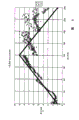
也就是说,如图15(a)所示,在液晶显示装置中,源极线Si(i是整数)和栅极线Gj(j是整数)设置为相互正交,在各个源极线和各个栅极线的交叉部分上,设置显示像素100以及开关元件200。而且,显示像素100...之中,在显示像素(A)中,形成有以下的寄生电容Csda·Csdb·Cgd·Ccs。而且,显示像素(B)表示和显示像素(A)在栅极线的布设方向上邻接的显示像素。That is, as shown in FIG. 15(a), in the liquid crystal display device, the source line Si (i is an integer) and the gate line Gj (j is an integer) are arranged to be orthogonal to each other, and each source line and
即,Right now,
寄生电容Csda...在用于驱动显示像素(A)的源极线S2和显示像素(A)之间形成的寄生电容Parasitic capacitance Csda...a parasitic capacitance formed between the source line S2 for driving the display pixel (A) and the display pixel (A)
寄生电容Csdb...在用于驱动显示像素(B)的源极线S3和显示像素(A)之间形成的寄生电容Parasitic capacitance Csdb...a parasitic capacitance formed between the source line S3 for driving the display pixel (B) and the display pixel (A)
寄生电容Cgd...在用于驱动显示像素(A)的栅极线G2和显示像素(A)之间形成的寄生电容Parasitic capacitance Cgd...a parasitic capacitance formed between the gate line G2 for driving the display pixel (A) and the display pixel (A)
寄生电容Ccs...在公共电极线和显示像素(A)之间形成的寄生电容。Parasitic capacitance Ccs... A parasitic capacitance formed between the common electrode line and the display pixel (A).
而且,显示像素(A)自身的电容为Cp,施加在各个栅极线上的电压如图15(b)所示那样的变化。而且,显示像素(A)显示G色,另一方面,显示像素(B)显示R色或者B色,使显示像素(A)的显示灰度为LA,显示像素(B)的显示等级为LB时,使LA≠LB。Furthermore, the capacitance of the display pixel (A) itself is Cp, and the voltage applied to each gate line changes as shown in FIG. 15( b ). Moreover, the display pixel (A) displays G color, on the other hand, the display pixel (B) displays R color or B color, so that the display grayscale of the display pixel (A) is LA, and the display level of the display pixel (B) is LB. , make LA≠LB.
该场合,栅极高电压的时候,在显示像素(A)的液晶部分上仅施加漏电压+V(A),在显示像素(B)的液晶部分上仅施加漏电压-V(B)。而且,在接下来的栅极线成为ON的时候,在驱动显示像素(A)的源极线上施加-V(A),在驱动显示像素(B)的源极线上施加+V(B)。In this case, when the gate voltage is high, only the drain voltage +V(A) is applied to the liquid crystal part of the display pixel (A), and only the drain voltage -V(B) is applied to the liquid crystal part of the display pixel (B). Then, when the next gate line is turned ON, -V(A) is applied to the source line for driving the display pixel (A), and +V(B) is applied to the source line for driving the display pixel (B). ).
然而,实际上显示像素(A)中,由于并没有原样施加上述的漏电压,而是施加的受到寄生电容的影响发生了变化的漏电压。具体而言,施加在显示像素(A)上的电压的有效值为Va,However, in actual display pixel (A), since the above-mentioned drain voltage is not applied as it is, a drain voltage changed due to the influence of parasitic capacitance is applied. Specifically, the effective value of the voltage applied to the display pixel (A) is Va,
Va=V(A)+(Csda*V(A)+Cgd*Vg+Csdb*V(B)+Ccs*Vc)/CpVa=V(A)+(Csda*V(A)+Cgd*Vg+Csdb*V(B)+Ccs*Vc)/Cp
而且,Vg是施加在栅极线上的电压,Vc是施加在对置电极上的电压。Also, Vg is the voltage applied to the gate line, and Vc is the voltage applied to the counter electrode.
这样,在显示像素(A)上,施加了与期望的漏电压(A)不同的电压。Thus, a voltage different from the desired drain voltage (A) is applied to the display pixel (A).
其中,在显示像素(A)之间形成的寄生电容Csda·Cgd·Ccs,由于可以在设计阶段进行预测,可以设定考虑了该寄生电容的值的漏电压。换句话说,这些寄生电容,对显示像素(A)的显示灰度基本没有什么影响。Here, since the parasitic capacitance Csda·Cgd·Ccs formed between the display pixels (A) can be predicted at the design stage, the drain voltage can be set in consideration of the value of the parasitic capacitance. In other words, these parasitic capacitances basically have no effect on the display grayscale of the display pixel (A).
然而,上述的有效电压Va的计算公式中包含,寄生电容Csdb,漏电压V(B)。即,电压Va还受到与显示像素(B)连接的源极线的影响,所以产生由显示像素(B)的显示灰度引起的显示像素(A)的灰度发生变化的色彩串扰。However, the above formula for calculating the effective voltage Va includes the parasitic capacitance Csdb and the drain voltage V(B). That is, the voltage Va is also affected by the source line connected to the display pixel (B), so color crosstalk occurs in which the gradation of the display pixel (A) changes due to the display gradation of the display pixel (B).
例如,V(A)=±2.59,V(B)=±1.21V的时候,供给显示像素(A)的电压为±2.45V,可知产生了色彩平衡的变化。For example, when V(A)=±2.59 and V(B)=±1.21V, the voltage supplied to the display pixel (A) is ±2.45V, and it can be seen that the color balance changes.
此外,如专利文献3所述,即使在设计阶段减少了寄生电容,仅仅能够减小串扰量,不能完全的避免色彩串扰。因此,实际上施加在显示像素上的电位,相应于显示装置整体的显示图案发生变动。结果是,显示像素不能再现所期望的亮度。In addition, as described in
此外,通过重新设置遮蔽电极和布线,也能使得对串扰进行一定的补偿,但是要在显示装置中设计新的结构,提高了显示装置的制造成本。In addition, crosstalk can also be compensated to a certain extent by re-arranging the shielding electrodes and wiring, but a new structure needs to be designed in the display device, which increases the manufacturing cost of the display device.
发明简述Brief description of the invention
本发明是用于解决上述问题的技术方案,目的在于提供一种高效率的降低串扰的显示装置的驱动方法,显示装置,以及程序。The present invention is a technical solution for solving the above problems, and aims to provide a high-efficiency driving method of a display device with reduced crosstalk, a display device, and a program.
为了解决上述问题,本发明的显示装置的驱动方法是配置有显示像素的显示装置的驱动方法,显示像素包含有在多个栅极线和多个源极线的交叉部分分别对应的开关元件和像素电极,其特征在于:由于与同一个栅极线连接的第1显示像素和第2显示像素,与和该第1显示像素连接的源极线邻接的同时在该第1显示像素的像素电极之间形成寄生电容的源极线,作为与上述第2显示像素连接的部件,基于向第2显示像素输入的信号或者向第2显示像素写入的信号,将向上述第1显示像素写入的信号、向第1显示像素的输入信号作为校正信号。In order to solve the above-mentioned problems, the driving method of the display device of the present invention is a driving method of a display device configured with display pixels, and the display pixels include switching elements and switching elements respectively corresponding to intersections of multiple gate lines and multiple source lines. The pixel electrode is characterized in that: since the first display pixel and the second display pixel connected to the same gate line are adjacent to the source line connected to the first display pixel, the pixel electrode of the first display pixel The source line forming a parasitic capacitance between them, as a component connected to the second display pixel, writes to the first display pixel based on the signal input to the second display pixel or the signal written to the second display pixel. The signal and the input signal to the first display pixel are used as the correction signal.
此外,为了解决上述问题,本发明的显示装置是配置有显示像素和开关元件的显示装置,其配置成多个栅极线和多个源极线在交叉的部分分别对应,其特征在于:由于与同一个栅极线连接的第1显示像素和第2显示像素,与和该第1显示像素连接的源极线邻接的同时在该第1显示像素的像素电极之间形成寄生电容的源极线,与上述第2显示像素连接,基于向第2显示像素的输入信号或者向第2显示像素的写入信号,将向上述第1显示像素写入的信号、向第1显示像素输入的信号作为校正信号。In addition, in order to solve the above-mentioned problems, the display device of the present invention is a display device configured with display pixels and switching elements, which are arranged such that a plurality of gate lines and a plurality of source lines correspond to crossing parts respectively, and is characterized in that: The first display pixel and the second display pixel connected to the same gate line are adjacent to the source line connected to the first display pixel, and the source electrode of the parasitic capacitance is formed between the pixel electrodes of the first display pixel. line connected to the second display pixel, based on the input signal to the second display pixel or the write signal to the second display pixel, the signal written to the first display pixel and the signal input to the first display pixel as a correction signal.
在配置有显示像素的显示装置中,该显示像素包含有其多个栅极线和多个源极线与各个交叉部分相对应的开关元件和像素电极,显示像素(第1显示像素)的像素电极的一部分,通过绝缘膜等和与该显示像素(第1显示像素)连接的源极线邻接的源极线(与第2显示像素连接的,驱动第2显示像素的源极线)重叠。与该第1显示像素的像素电极和第2显示像素连接的源极线的重叠部分形成寄生电容,对第1显示像素的像素电极电位产生影响。In a display device configured with display pixels, the display pixels include a plurality of gate lines and a plurality of source lines corresponding to the respective intersections of switching elements and pixel electrodes, and the pixels of the display pixels (first display pixels) Part of the electrode overlaps the source line (the source line connected to the second display pixel and driving the second display pixel) adjacent to the source line connected to the display pixel (first display pixel) through an insulating film or the like. The overlapping portion of the source line connected to the pixel electrode of the first display pixel and the second display pixel forms a parasitic capacitance, which affects the potential of the pixel electrode of the first display pixel.
其中,在上述结构中,基于向第2显示像素输入的信号或者向第2显示像素写入的信号,对向第1显示像素输入的信号进行校正,将它作为向第1显示像素写入的信号。换句话说,在预先考虑在驱动第1显示像素的像素电极和第2显示像素的源极线之间的寄生电容的影响的基础上决定写入第1显示像素的写入信号。其中,输入信号是向显示装置传送的各个像素产生的原来的灰度数据和电压数据,写入信号是实际上给予源极线的施加电压或者与该施加电压对应的灰度。上述第2显示像素的写入信号是,对第2显示像素的输入信号(电压数据或者灰度数据)进行校正的信号(电压或者灰度)。Wherein, in the above structure, based on the signal input to the second display pixel or the signal written to the second display pixel, the signal input to the first display pixel is corrected, and it is used as the input signal to the first display pixel. Signal. In other words, the write signal written into the first display pixel is determined in consideration of the influence of the parasitic capacitance between the pixel electrode driving the first display pixel and the source line of the second display pixel. Among them, the input signal is the original gradation data and voltage data generated by each pixel transmitted to the display device, and the writing signal is the applied voltage actually applied to the source line or the gradation corresponding to the applied voltage. The writing signal of the second display pixel is a signal (voltage or gradation) corrected for the input signal (voltage data or gradation data) of the second display pixel.
据此,能够大幅度降低在上述寄生电容使得第1显示像素的像素电极(个个像素电极)的电位发生变动的情况下产生的显示灰度与所期望的灰度之间的差距(串扰量),可以提高(色彩平衡的正常化)显示质量。Accordingly, it is possible to significantly reduce the difference between the display gradation and the desired gradation (the amount of crosstalk) that occurs when the potential of the pixel electrode (individual pixel electrodes) of the first display pixel fluctuates due to the above-mentioned parasitic capacitance. ), which can improve (normalization of color balance) display quality.
此外,本发明的显示装置是,在多个栅极线和多个源极线的交叉的部分上分别对应的配置包含开关元件和像素电极的显示像素的显示装置,其特征在于:第1栅极线以及邻接于与第1源极线连接的第1显示像素的第2源极线,与上述第2显示像素连接,并具备,实现了将第1显示像素的输入信号,基于第2显示像素的输入信号或者第2显示像素的写入信号,和上述第2源极线以及第1显示像素之间形成的寄生电容的电容值进行校正,并将它作为第1显示像素的写入信号的功能的校正回路。上述第2源极线和第1显示像素之间形成的寄生电容比如可以是第2源极线和第1显示像素的像素电极之间的寄生电容和第2源极线与开关元件的各个电极(漏电极等)之间的寄生电容。In addition, the display device of the present invention is a display device in which display pixels including switching elements and pixel electrodes are respectively arranged correspondingly at intersections of a plurality of gate lines and a plurality of source lines, and is characterized in that the first gate The electrode line and the second source line adjacent to the first display pixel connected to the first source line are connected to the above-mentioned second display pixel, and are provided to realize the input signal of the first display pixel based on the second display The input signal of the pixel or the write signal of the second display pixel is corrected with the capacitance value of the parasitic capacitance formed between the second source line and the first display pixel, and it is used as the write signal of the first display pixel The function of the correction loop. The parasitic capacitance formed between the second source line and the first display pixel may be, for example, the parasitic capacitance between the second source line and the pixel electrode of the first display pixel and the second source line and each electrode of the switching element. (Drain electrode, etc.) between the parasitic capacitance.
此外,本发明的显示装置是,在多个栅极线和多个源极线的交叉的部分上分别对应的配置包含开关元件和像素电极的显示像素的显示装置,其特征在于:对于连接于同一个栅极线的第1显示像素和第2显示像素,在邻接于和该第1显示像素连接的源极线的同时在该第1显示像素之间形成寄生电容的源极线,与上述第2显示像素连接,并具备,实现了将第1显示像素的输入信号,基于第2显示像素的输入信号或者第2显示像素的写入信号,和上述寄生电容的电容值进行校正,并将它作为第1显示像素的写入信号的功能的校正回路。上述寄生电容比如可以是,源极线和第1显示像素的像素电极之间的寄生电容和源极线和第1显示像素的开关元件的各个电极(比如,漏电极)之间的寄生电容。In addition, the display device of the present invention is a display device in which display pixels including switching elements and pixel electrodes are respectively arranged correspondingly at intersections of a plurality of gate lines and a plurality of source lines, and is characterized in that: The first display pixel and the second display pixel on the same gate line are adjacent to the source line connected to the first display pixel while forming a parasitic capacitance between the source lines of the first display pixel, and the above-mentioned The second display pixel is connected, and possesses the ability to correct the input signal of the first display pixel, based on the input signal of the second display pixel or the write signal of the second display pixel, and the capacitance value of the above parasitic capacitance, and It acts as a correction loop for the function of the write signal to the 1st display pixel. The above parasitic capacitance may be, for example, the parasitic capacitance between the source line and the pixel electrode of the first display pixel, and the parasitic capacitance between the source line and each electrode (for example, the drain electrode) of the switching element of the first display pixel.
而且,某个显示像素与源极线连接,表示该显示像素的像素电极通过该开关元件与源极线连接的意思。]Furthermore, the fact that a certain display pixel is connected to the source line means that the pixel electrode of the display pixel is connected to the source line via the switching element. ]
附图简述Brief description of the drawings
图1是详细的示出图2的彩色显示装置的显示面板的构成的平面图。FIG. 1 is a plan view showing in detail the configuration of a display panel of the color display device of FIG. 2 .
图2是本发明的显示装置的一个实施形式的彩色显示装置的构成的方块图。Fig. 2 is a block diagram showing the configuration of a color display device which is an embodiment of the display device of the present invention.
图3是示出图1的显示面板中的显示图案变化的状态的图形。FIG. 3 is a diagram illustrating a state in which a display pattern changes in the display panel of FIG. 1 .
图4是用于对比本来的白色亮度和合成的白色亮度的图。FIG. 4 is a graph for comparing original white luminance and synthesized white luminance.
图5是表示对本来的白色亮度的合成白色亮度的刺激值的误差率和显示灰度之间的关系的图。5 is a graph showing the relationship between the error rate of the stimulus value of the synthesized white luminance with respect to the original white luminance and the display gradation.
图6是图表法表示的校正灰度等级和显示灰度之间的关系的图。Fig. 6 is a graph showing the relationship between the corrected gradation level and the displayed gradation level.
图7是在将图6的校正灰度等级施加在显示像素(A)的灰度等级上的场合,表示显示灰度等级LA和刺激误差率之间的关系的图。Fig. 7 is a diagram showing the relationship between the display gradation level LA and the stimulus error rate when the correction gradation level of Fig. 6 is applied to the gradation level of the display pixel (A).
图8是使用配色例1的图1的显示面板处于配色状态的平面图。FIG. 8 is a plan view of the display panel in FIG. 1 using color matching example 1 in a color matching state.
图9是使用配色例2的图1的显示面板处于配色状态的平面图。FIG. 9 is a plan view of the display panel in FIG. 1 using color matching example 2 in a color matching state.
图10是使用配色例2的图1的显示面板处于配色状态的平面图。FIG. 10 is a plan view of the display panel in FIG. 1 using color matching example 2 in a color matching state.
图11是使用配色例3的图1的显示面板处于配色状态的平面图。FIG. 11 is a plan view of the display panel in FIG. 1 using color matching example 3 in a color matching state.
图12是使用连接例1的图1的显示面板的源极线和显示像素的连接状态的平面图。12 is a plan view of a connection state of source lines and display pixels of the display panel of FIG. 1 using connection example 1. FIG.
图13是使用连接例2的图1的显示面板的源极线和显示像素的连接状态的平面图。13 is a plan view of a connection state of source lines and display pixels of the display panel of FIG. 1 using connection example 2. FIG.
图14是本发明的显示装置的其它的实施形式的彩色显示装置的结构的方块图。14 is a block diagram showing the configuration of a color display device in another embodiment of the display device of the present invention.
图15(a)是在先的液晶显示装置的显示面板的结构的图,(b)是向栅极线施加的电压的状态的图。FIG. 15( a ) is a diagram showing the configuration of a display panel of a conventional liquid crystal display device, and FIG. 15( b ) is a diagram showing the state of voltages applied to gate lines.
图16(a)(b)是表示本发明的CCT校正回路的处理步骤的方块图。16(a)(b) are block diagrams showing the processing steps of the CCT correction circuit of the present invention.
图17是本发明的其它的CCT校正回路的处理步骤的方块图。Fig. 17 is a block diagram of the processing steps of another CCT correction loop of the present invention.
具体实施例specific embodiment
对于本发明的一个实施形式,基于附图进行说明。One embodiment of the present invention will be described based on the drawings.
[显示装置的结构][Structure of Display Device]
图2是本发明的彩色显示装置1(显示装置)的一个实施形式。如图所示,彩色显示装置1具备CCT(色彩串扰)校正回路2,极性翻转回路3,定时控制器4,源极驱动器5,栅极驱动器6,显示面板7和存储部8。而且,图2中,大幅度省略了与本发明无关的结构。FIG. 2 is an embodiment of the color display device 1 (display device) of the present invention. As shown in the figure, a
CCT校正回路2是本发明的特征部分的结构,对由从外部输入的表示R色(第1显示色)的灰度等级的红色信号R,表示G色(第2显示色)的灰度等级的绿色信号G,表示B色(第2显示色)的灰度等级的蓝色信号B构成的输入信号灰度(输入彩色信号)进行校正,显示面板7中输出向各个显示像素(像素组图中未示出)的写入信号灰度(输出彩色影像信号)R’,G’,B’。而且,还可以是第1显示色为青色,第2显示色为品红色,第3显示色为黄色。而且,CCT校正回路2优选包含色度强调回路10。The
CCT校正回路2通过将输入的彩色影像信号R·G·B锁存并每1点地进行延迟的方式,对与同一个源极线连接的2个显示像素进行后述的处理。The
极性翻转回路3,基于从CCT校正回路2输出的写入信号灰度R’,G’,B’(数字数据),决定写入显示面板的各个显示像素的写入电压信号(模拟数据)。The
本彩色显示装置1(显示装置)中,如图14所示,CCT校正回路还可以设置在极性翻转回路3的前段。换句话说,图14所示的CCT校正回路2,校正来自极性翻转回路3的输入信号电压(模拟数据),输出写入电压信号(模拟数据)。In the color display device 1 (display device), as shown in FIG. 14 , the CCT correction circuit can also be provided in the front stage of the
定时控制器4基于输入的RGB同期信号,产生用于驱动源极驱动器5和栅极驱动器6的源极驱动器用定时信号以及栅极驱动器用定时信号。而且,源极驱动器用定时信号通过极性翻转回路3输入到源极驱动器5。The
源极驱动器5将由极性翻转回路3决定的写入电压施加到各个显示像素上,驱动与在显示面板7上设置的各个显示像素通过TFT连接的各个源极线。而且,源极驱动器5还可以与极性翻转回路3一体形成。此外,栅极驱动器6也是用于驱动与在显示面板7上设置的各个显示像素通过TFT连接的各个栅极线的装置。The
显示面板7是被矩阵状配置的多个显示像素,通过用多个源极线和多个栅极线驱动的方式进行图像显示的装置。具体而言,如图1所示,将源极线Si(i为整数)和栅极线Gj(j为整数)设置为正交的形式,在各个源极线和各个栅极线的交叉部分上,设置包含显示像素11和开关元件12的各显示象素。The
其中,显示像素11...之中,对用同样的栅极线G2驱动的2个显示像素,如图1所示,与该第1显示像素(A)连接的源极线S2邻接的同时在该第1显示像素(A)的像素电极之间形成寄生电容的源极线S3,与上述第2显示像素(B)连接的场合,在显示像素(A)的周围,形成以下的寄生电容Csda·Csdb·Cgd·Ccs。Among the
寄生电容Csda...在用于驱动显示像素(A)的源极线和显示像素(A)之间形成的寄生电容Parasitic capacitance Csda...A parasitic capacitance formed between the source line for driving the display pixel (A) and the display pixel (A)
寄生电容Csdb...在用于驱动显示像素(B)的源极线和显示像素(A)之间形成的寄生电容Parasitic capacitance Csdb...a parasitic capacitance formed between the source line for driving the display pixel (B) and the display pixel (A)
寄生电容Cgd...在用于驱动显示像素(A)的栅极线和显示像素(A)之间形成的寄生电容Parasitic capacitance Cgd...A parasitic capacitance formed between the gate line for driving the display pixel (A) and the display pixel (A)
寄生电容Ccs...在公共电极线和显示像素(A)之间形成的寄生电容。Parasitic capacitance Ccs... A parasitic capacitance formed between the common electrode line and the display pixel (A).
由此,不用通过CCT校正回路2像现有技术那样驱动各个显示像素11...,关注显示像素的显示灰度,会产生由于受到向驱动其它的显示像素的源极线施加的电压的影响得到与所期望的灰度不同的结果的称为串扰的问题。例如,如图1所示的结构中,关注作为第1显示像素的显示像素(A)的话,显示像素(A)的显示灰度就会受到,向驱动作为第2显示像素的显示像素(B)的源极线S3所施加的电压的影响。Therefore, instead of driving each
本实施形式的彩色显示装置1中,设置CCT校正回路2(参照图2,图14)正是用于改善产生这样的串扰的问题。In the
其中,使用图16·17,对CCT校正回路2的写入信号的输出步骤进行说明。Here, the output procedure of the writing signal of the
图16是对使用CCT校正回路2,将显示像素(A)的输入信号灰度基于显示像素(B)的输入信号灰度进行校正,将它作为显示像素(A)的写入信号灰度输出到极性翻转回路3的场合进行说明的方块图。Fig. 16 is to use the
首先,左侧的显示像素(A)的输入信号灰度,在每一个点的存储在存储器中的同时向CCT校正回路2输入(图16(a))。接着,如同一个图的(b)中所示,显示像素(B)的输入信号灰度也在每一个点的存储在存储器中的同时向CCT校正回路2输入,此时,从每一个点存储器中将先前存储的显示像素(A)的输入信号灰度输出,与显示像素(B)的输入信号灰度一起输入到CCT校正回路2。CCT校正回路2中,将来自该每一个点存储器中的显示像素(A)的输入信号灰度,基于显示像素(B)的输入信号灰度进行校正,将他们作为显示像素(A)的写入信号灰度输出到极性翻转回路3。First, the input signal gradation of the left display pixel (A) is input to the
图17是对使用CCT校正回路2’,将显示像素(A)的输入信号灰度基于显示像素(B)的写入信号灰度进行校正,将它作为显示像素(A)的写入信号灰度输出到极性翻转回路3的场合进行说明的方块图。Fig. 17 uses the CCT correction circuit 2' to correct the input signal grayscale of the display pixel (A) based on the written signal grayscale of the display pixel (B), and use it as the written signal grayscale of the display pixel (A) A block diagram illustrating the case where the degree is output to the
扫描方向设定为显示像素(A)→显示像素(B)的方向,首先,将与扫描端(图中右端)的源极线相连接的显示像素(n)的输入信号灰度输入到CCT校正回路2的同时,将除了该显示像素(n)之外的所有的显示像素的输入信号灰度存储在一个线存储器中。显示像素(n)的输入信号灰度在CCT校正回路2’中校正,在存储在一个线存储器的同时作为显示像素(n)的写入信号灰度输出到CCT校正回路2’。其中,CCT校正回路2从线存储器中读取显示像素(n-1)的输入信号灰度,将它基于输入的显示像素(n)的写入信号灰度进行校正,作为显示像素(n-1)的写入信号灰度输出的同时将它存储在一个线存储器中。按照这个顺序进行,如果将显示像素(B)的写入信号灰度存储在1个线存储器中的同时输出到CCT校正回路2’,CCT校正回路2’从1个线存储器中读取显示像素(A)的输入信号灰度,将它基于输入的上述显示像素(B)的写入信号灰度进行校正并作为显示像素(A)的写入信号灰度输出的同时存储在1个线存储器中。The scanning direction is set as the direction of display pixel (A)→display pixel (B). First, input the gray level of the input signal of the display pixel (n) connected to the source line of the scanning end (right end in the figure) to the CCT While correcting
结果,在1个线存储器中,能够存储所有的显示像素的写入信号灰度,适当的向极性翻转回路3输出。此时,由于将写入信号灰度向显示面板输出的顺序与该线的顺序相反,需要进行适当的顺序转换。As a result, the write signal gradations of all the display pixels can be stored in one line memory, and output to the
在校正(向1个线存储器的存储)方向和各线的扫描方向相反的场合,与各个线对应的写入信号灰度按照各个线的扫描方向输出到极性翻转回路。When the correction (storage in one line memory) direction is opposite to the scanning direction of each line, the write signal gradation corresponding to each line is output to the polarity inversion circuit according to the scanning direction of each line.
而且,如果将扫描方向设定为显示像素(B)→显示像素(A)的方向,首先,将与扫描端(图中的右端)的源极线相连接的显示像素(n)的输入信号灰度输入到CCT校正回路(图中未示出),作为显示像素(n)的写入信号灰度输出到极性翻转回路3。此时,如果将显示像素(n-1)的输入信号灰度输入到CCT校正回路,将它基于上述显示像素(n)的写入信号灰度进行校正,作为显示像素(n-1)的写入信号灰度输出。按照这个顺序进行,将显示像素(B)的输入信号灰度输入到CCT校正回路2,并将显示像素(B)的写入信号灰度输出的话,此时输入的显示像素(A)的输入信号灰度,基于该显示像素(B)的写入信号灰度进行校正,作为显示像素(A)的写入信号灰度输出。Furthermore, if the scanning direction is set to display pixel (B)→display pixel (A), first, the input signal of the display pixel (n) connected to the source line of the scanning end (the right end in the figure) is The gray scale is input to the CCT correction circuit (not shown in the figure), and output to the
这样的话,将各个显示像素的写入信号灰度依次输出到极性翻转回路3。在该扫描方向的场合,可以省略1个线存储器。In this case, the gray levels of the writing signals of the respective display pixels are sequentially output to the
[2.关于串扰的校正处理][2. Correction processing for crosstalk]
[2-1.关于亮度平衡的变动][2-1. About changes in brightness balance]
在本实施形式的彩色显示装置1中,设置CCT校正回路2是用于改善产生串扰的问题。通过这样的两个回路能够使得输入彩色影像信号的校正顺序非常清楚,所以对每个显示图案的亮度平衡的变动进行下列说明。In the
例如,如图3所示的图案1-3用显示面板7进行显示。具体而言,对于图案1,在邻接的6个显示像素上,从左开始顺序为,R色,G色,B色,黑色,黑色,黑色的进行显示。对于图案2来说,是以黑色,G色,B色,R色,黑色,黑色的顺序进行显示。对于图案3来说,是以黑色,黑色,B色,R色,G色,黑色的顺序进行显示。For example, the pattern 1-3 shown in FIG. 3 is displayed by the
这样的图案1-3分别显示在显示面板7上的图像,应该是完全相同的。然而实际上,向显示黑色的显示像素(灰度等级为0的显示像素)的左边的显示像素上施加的电压,受到向显示黑色的显示像素所施加的电压的影响。这样,在该左边的像素中,使得显示出了比期望的灰度等级稍低的灰度等级。The images of such patterns 1-3 respectively displayed on the
例如,在图案1中,B色的显示像素在黑色的显示像素的旁边,使得显示的B色以比期望的灰度等级稍低的灰度等级进行显示。同样的,图案2中R色以比期望的灰度等级稍低的灰度等级进行显示,图案3中G色以比期望的灰度等级稍低的灰度等级进行显示。这样,使得在显示面板上的显示图案中,邻接的多个显示像素之间的亮度平衡发生了变动。For example, in
此外,考虑到邻接的3个显示像素进行白色的显示的场合,如图4的等式的左边所示,在3个显示像素从左开始按顺序为R色,G色,B色进行显示的状态下,能够进行理想的白色的显示。In addition, considering the case where three adjacent display pixels display white, as shown on the left side of the equation in FIG. In this state, an ideal white display can be performed.
另一方面,对于邻接的3个显示像素,在同一个等式的右边所示,通过在下面的图案4-6中分别进行显示切换的方法,也应该能够显示白色。On the other hand, for the three adjacent display pixels, as shown on the right side of the same equation, it should be possible to display white by performing display switching in each of the following patterns 4-6.
即,对于图案4-6,将3个显示像素各自的显示颜色从左边的像素开始依次记载的话,为That is, for Pattern 4-6, if the respective display colors of the three display pixels are described sequentially from the left pixel, it is
图案4:R色,黑色,黑色Pattern 4: R color, black, black
图案5:黑色,G色,黑色Pattern 5: black, G color, black
图案6:黑色,黑色,B色Pattern 6: black, black, B color
也就是说,本来的白色亮度应该等于合成的白色亮度(红亮度+绿亮度+蓝亮度-2*黑亮度),实际上,合成的白色亮度最好比白色亮度低。所以,如上所述,是由于受到对黑色显示像素的施加电压的拉动,向R,G,或者B色的显示像素施加的电压发生变化引起的。That is to say, the original white brightness should be equal to the synthesized white brightness (red brightness + green brightness + blue brightness - 2*black brightness), in fact, the synthesized white brightness is preferably lower than the white brightness. Therefore, as described above, the voltage applied to the display pixel of the R, G, or B color changes due to the pull of the voltage applied to the black display pixel.
对本来的白色亮度的合成白色亮度的刺激值的误差率和显示灰度之间的关系如图5那样。而且,在图5中,与注目显示像素邻接的显示像素的灰度等级是0的场合,注目显示像素的灰度等级表示在横轴上。例如,将图1所示的结构的显示面板中的显示像素(A)作为注目显示像素的话,图5的横轴中所示的显示灰度可以考虑表示为,在显示像素(B)的灰度等级LB为0时显示像素(A)的灰度等级LA。The relationship between the error rate of the stimulus value of the synthesized white luminance with respect to the original white luminance and the display gradation is shown in FIG. 5 . Furthermore, in FIG. 5, when the gradation level of the display pixel adjacent to the display pixel of interest is 0, the gradation level of the display pixel of interest is indicated on the horizontal axis. For example, if the display pixel (A) in the display panel with the structure shown in FIG. 1 is used as the display pixel of interest, the display gray scale shown in the horizontal axis of FIG. When the level LB is 0, the gray level LA of the pixel (A) is displayed.
下面,为了说明的方便,将图5的横轴,作为表示显示像素(A)的灰度等级LA的轴。Hereinafter, for convenience of description, the horizontal axis in FIG. 5 is taken as the axis representing the gray level LA of the display pixel (A).
如图5所示,灰度等级LA在低灰度等级侧的场合,刺激误差率的变化较大。也就是说,对于图5,灰度等级LA为从0到128之间的值的时,刺激误差率的弧线表示为陡峭地倾斜。另一方面,灰度等级LA超过128的情况下,从刺激误差率的弧线表示为不是非常陡峭,可以看出刺激误差率的变化较小。As shown in FIG. 5 , when the gradation level LA is on the low gradation level side, the variation in the stimulus error rate is large. That is to say, with regard to FIG. 5 , when the gray level LA is a value between 0 and 128, the arc of the stimulus error rate shows a steep slope. On the other hand, when the gradation level LA exceeds 128, the arc of the stimulus error rate is not very steep, and it can be seen that the change of the stimulus error rate is small.
而且,为了对注目显示像素中的合成白色亮度进行校正使其接近于本来的白色亮度,所需要的校正灰度等级是通过将各个灰度的刺激值的误差率从该灰度的刺激值的变化率中分离求出的。图6中,校正灰度等级和显示灰度之间的关系用图表化的图来表示。Furthermore, in order to correct the composite white luminance in the display pixel of interest so that it is close to the original white luminance, the corrected gray level is obtained by dividing the error rate of the stimulus value of each gray scale from the stimulus value of the gray scale Calculated separately from the rate of change. In FIG. 6 , the relationship between the corrected gradation level and the display gradation level is shown graphically.
即,图6是将图5的刺激值用接近的灰度中的刺激值变化率进行除法运算得到的两作为变换成实际灰度的值。That is, FIG. 6 is a value obtained by dividing the stimulus value in FIG. 5 by the rate of change of the stimulus value in a close gray scale and converting it into an actual gray scale.
如图6所示,比如显示像素(A)的灰度等级LA为0的场合中,校正灰度等级大致为0。而且,随着灰度等级LA接近128,校正灰度等级也增加。另一方面,灰度等级LA超过128的情况下,校正灰度等级LA和校正灰度等级之间的相关关系变得不明了。As shown in FIG. 6 , for example, when the gradation level LA of the display pixel (A) is 0, the corrected gradation level is approximately 0. Also, as the gradation level LA approaches 128, the corrected gradation level also increases. On the other hand, when the gradation level LA exceeds 128, the correlation between the corrected gradation level LA and the corrected gradation level becomes unclear.
而且,图6是假定与图5相同的灰度等级LB为0、表示灰度等级LA和校正灰度之间的关系。灰度等级LB成为一个比0还要大的值的场合,与该LB的值对应的以一定量减少校正灰度等级。而且,LB≥LA的时候,校正灰度等级为0。Furthermore, FIG. 6 shows the relationship between the gray level LA and the corrected gray level assuming that the gray level LB is 0 as in FIG. 5 . When the gradation level LB has a value greater than 0, the correction gradation level is reduced by a certain amount corresponding to the value of LB. Moreover, when LB≥LA, the corrected gray level is 0.
这里参照图5可以知道,对于低灰度其误差率的变化较大。对于显示像素(A)显示低等级的灰度的场合,具有较大的必要性来对合成亮度进行调整精度的校正。Referring to FIG. 5 here, it can be seen that the error rate varies greatly for low gray levels. When the display pixel (A) displays a low-level gradation, it is highly necessary to correct the adjustment accuracy of the combined luminance.
因此,如图6所示,在灰度等级为从0到128的范围中的时候显示灰度等级和校正灰度等级之间的关系用直线表示,能够计算出与灰度等级相应的合适的校正灰度。这样,灰度等级LA在低灰度侧的场合的合成灰度的校正能够以更高的精度进行。Therefore, as shown in FIG. 6, when the gray scale is in the range from 0 to 128, the relationship between the displayed gray scale and the corrected gray scale is represented by a straight line, and the appropriate gray scale corresponding to the gray scale can be calculated. Correct grayscale. In this way, when the gradation level LA is on the low gradation side, the composite gradation can be corrected with higher accuracy.
另一方面,灰度等级LA在高灰度侧的场合中,比如在128以上的场合中,灰度等级LA和校正灰度等级之间的相对关系变得不明了。因此,灰度等级LA超过128的场合,可以将校正灰度等级设定为一定值来进行比较粗略的校正。On the other hand, when the gradation level LA is on the high gradation side, for example, 128 or higher, the relative relationship between the gradation level LA and the corrected gradation level becomes unclear. Therefore, when the gradation level LA exceeds 128, relatively rough correction can be performed by setting the corrected gradation level to a constant value.
如上那样设定的校正灰度等级施加在显示像素(A)的灰度等级上的场合,显示灰度等级LA和刺激误差率之间的关系如图7所示。如图7所示,通过施加校正灰度等级的方式,能够将刺激误差率从最大的25%降低到5%。When the correction gradation level set as above is applied to the gradation level of the display pixel (A), the relationship between the display gradation level LA and the stimulus error rate is shown in FIG. 7 . As shown in Figure 7, by applying the correction gray scale, the stimulus error rate can be reduced from a maximum of 25% to 5%.
[2-2.关于使用灰度等级数据的串扰的校正][2-2. Regarding correction of crosstalk using gradation data]
根据这些讨论结果,用CCT校正回路,基于显示像素(B)的输入信号灰度或者写入信号灰度对写入显示像素(A)的信号灰度、显示像素(A)的输入信号灰度进行了校正的灰度能够降低串扰量。也就是说,通过基于向显示像素(B)的输入信号灰度或者写入信号灰度对向显示像素(A)的输入信号灰度进行校正的方法,在考虑到显示像素(A)受到的来自显示像素(B)的由寄生电容产生的影响的基础上,能够确定相对显示像素(A)的写入信号灰度。因此,能够降低寄生电容Csd和显示像素之间产生的串扰量,使得显示装置的显示的色彩平衡正常化。According to these discussion results, using the CCT correction circuit, based on the grayscale of the input signal of the display pixel (B) or the grayscale of the written signal, the grayscale of the signal written to the display pixel (A), the grayscale of the input signal of the display pixel (A) Corrected grayscale reduces the amount of crosstalk. That is, by correcting the gray scale of the input signal to the display pixel (A) based on the gray scale of the input signal to the display pixel (B) or the gray scale of the written signal, in consideration of the Based on the influence of the parasitic capacitance from the display pixel (B), the gradation of the writing signal to the display pixel (A) can be determined. Therefore, the amount of crosstalk generated between the parasitic capacitance Csd and the display pixels can be reduced, and the color balance of the display of the display device can be normalized.
具体而言,在数字数据表示的显示像素(A)的灰度等级为LA,同样的数字数据表示的显示像素(B)的灰度等级为LB,以上述LA和上述LB为输入值的函数为F(LA,LB)的场合中,将输入到显示像素(A)的输入灰度等级校正为根据用Lout=LA+F(LA,LB)计算出的灰度等级Lout。Specifically, the gray level of the display pixel (A) represented by the digital data is LA, and the gray level of the display pixel (B) represented by the same digital data is LB, and the above-mentioned LA and the above-mentioned LB are functions of input values In the case of F(LA, LB), the input gradation level input to the display pixel (A) is corrected to the gradation level Lout calculated by Lout=LA+F(LA, LB).
这样的对灰度等级LA进行校正,由于使用了数字数据的灰度等级对向显示像素(A)的输入信号灰度进行了校正,能够通过简单的处理降低串扰。也就是说,用表示施加电压的模拟数据对向显示像素(A)的施加电压进行校正的话,由于存在比使用数字数据更多的位数需要处理的场合,使得处理非常困难。在使用数字数据的校正处理中,能够避免这样的处理的困难化的问题。Such correction of the gradation level LA corrects the gradation of the input signal to the display pixel (A) using the gradation level of the digital data, so that crosstalk can be reduced by simple processing. In other words, when the voltage applied to the display pixel (A) is corrected using analog data representing the applied voltage, processing is very difficult because more bits need to be processed than when using digital data. In the correction processing using digital data, it is possible to avoid such a problem of making the processing difficult.
而且,上述LA比预定的阈值更小时,定义为F(LA,LB)=k(LA-LB)(但是,k>0),上述LA大于该阈值时,优选将F(LA,LB)定义为一个输出一定值的函数。Moreover, when the above-mentioned LA is smaller than a predetermined threshold value, it is defined as F(LA, LB)=k(LA-LB) (however, k>0), and when the above-mentioned LA is larger than the threshold value, it is preferable to define F(LA, LB) as is a function that outputs a certain value.
也就是说,为了降低串扰而应该施加给LA的校正值F(LA,LB)的值,如图6所示,直到到达LA为预定的阈值(128灰度)前,LA的值相应的单调增加。此外,对于LA超过阈值(128灰度)的情况,LA和F(LA,LB)之间的相对关系变得不明了。此外,如图5所示,由于刺激值的误差率降低,在LA上施加一定值的输出Lout,用比较粗略的校正方式降低串扰。That is to say, in order to reduce the crosstalk, the value of the correction value F(LA, LB) that should be applied to LA, as shown in Figure 6, until it reaches the predetermined threshold value (128 gray levels) of LA, the value of LA is correspondingly monotonous Increase. Furthermore, for the case where LA exceeds the threshold (128 gray levels), the relative relationship between LA and F(LA, LB) becomes unclear. In addition, as shown in Figure 5, since the error rate of the stimulus value is reduced, a certain value of output Lout is applied to the LA, and the crosstalk is reduced by a relatively rough correction method.
因此,定义上述那样的F(LA,LB)的话,能够用简略的处理求出Lout。Therefore, if F(LA, LB) as described above is defined, Lout can be obtained by simple processing.
而且,从0到最大灰度等级中包含的整数中抽取出多个整数,一方面将在该多个整数分别作为LA的场合中的F(LA,0)的值,与对应的LA的值相关联的储存在预设的查询表中,而且,优选将输入了上述查询表中没有储存的LA的F(LA,LB)的值,基于在该查询表中存储的LA的值,与该LA的值对应的F(LA,0)的值,和满足F(LA,LB)=0的LA和LB的值进行内插。Moreover, a plurality of integers are extracted from the integers contained in 0 to the maximum gray level. On the one hand, the value of F(LA, 0) in the case where the plurality of integers are respectively used as LA, and the value of the corresponding LA The association is stored in a preset look-up table, and, preferably, the value of F(LA, LB) for which LA not stored in the above-mentioned look-up table is input is based on the value of LA stored in the look-up table, and the The value of F(LA, 0) corresponding to the value of LA is interpolated with the values of LA and LB satisfying F(LA, LB)=0.
根据上述结构,由于能够使用查询表求出F(LA,LB)的值,所以将该查询表根据显示装置的各个种类预先制作,而且在存储部8(参照图2)中进行储存,能够相应于显示装置的种类求出合适的F(LA,LB)的值。According to the above structure, since the value of F(LA, LB) can be obtained using the look-up table, the look-up table is created in advance according to each type of display device, and stored in the storage unit 8 (see FIG. Find an appropriate value of F(LA, LB) depending on the type of display device.
而且,LA>LB的场合,上述内插优选用直线内插的方式。作为内插方法,直线的内插也是最简单的方法。Furthermore, in the case of LA>LB, it is preferable to use a linear interpolation method for the above-mentioned interpolation. As an interpolation method, linear interpolation is also the simplest method.
此外,LA<LB的场合,优选定义为F(LA,LB)=0。In addition, when LA<LB, it is preferable to define F(LA, LB)=0.
LA<LB的场合,由于显示像素(A)的灰度等级低,源极线和第1显示像素之间即使产生了串扰,该串扰对显示像素(A)的显示等级所带来的影响也很小。换句话说,LA<LB的场合,还可以不用特别的求出校正值F(LA,LB)。所以,LA<LB的场合,优选定义为F(LA,LB)=0。In the case of LA<LB, since the gray level of the display pixel (A) is low, even if there is crosstalk between the source line and the first display pixel, the influence of the crosstalk on the display level of the display pixel (A) is small. very small. In other words, in the case of LA<LB, the correction value F(LA, LB) need not be obtained in particular. Therefore, when LA<LB, it is preferable to define F(LA, LB)=0.
[2-3.关于使用施加电压数据的串扰的校正][2-3. About correction of crosstalk using applied voltage data]
此外,上述说明中,虽然对使用显示像素(A)的输入信号灰度等级LA和显示像素(B)的灰度(输入信号灰度,写入信号灰度)等级LB,来决定至显示像素(A)的写入信号灰度的方法进行了说明,但是也不是一定要使用这样的处理。即,还可以基于表示向显示像素(A)的写入信号电压的模拟数据,以及表示向显示像素(B)的施加电压(输入信号电压,写入信号电压)的模拟数据,决定向显示像素(A)的写入信号电压。对该校正顺序在下面进行说明。而且,使用表示施加电压的模拟数据的校正操作与使用表示灰度等级的数字数据的校正类似,是用CCT校正回路来实行的。但是,由于必须将表示向各个像素的施加电压的模拟数据输入到CCT校正回路,如图14所示,必须将极性翻转回路设置在CCT校正回路的前面。In addition, in the above description, although the input signal grayscale LA of the display pixel (A) and the grayscale (input signal grayscale, write signal grayscale) level LB of the display pixel (B) are used to determine the display pixel The method of writing signal gradation in (A) has been described, but such processing is not necessarily used. In other words, it is also possible to determine the input signal to the display pixel (A) based on the analog data indicating the voltage of the signal to be written to the display pixel (A) and the analog data indicating the voltage (input signal voltage, input signal voltage) to the display pixel (B). (A) Write signal voltage. This correction procedure will be described below. Also, the correction operation using analog data representing the applied voltage is carried out by a CCT correction circuit similarly to the correction using digital data representing gray levels. However, since it is necessary to input the analog data representing the voltage applied to each pixel to the CCT correction circuit, as shown in FIG. 14 , it is necessary to provide the polarity inversion circuit before the CCT correction circuit.
在基于表示施加电压的模拟数据的校正步骤中,在显示像素(A)的电容值为Cp,显示像素(B)的开关元件所连接的源极线和与显示像素(A)连接的寄生电容的电容值为Csd,灰度等级为g的时候的显示像素(A)的施加电压(输入信号电压)为U(g),向显示像素(B)的施加电压(输入信号电压或者写入信号电压)为Ugad,向公共电极的施加电压(显示黑色的时候的显示像素(A)的施加电压)为Ubad的时候,将用F(g)=Csd·(Ugad-Ubad)/Cp·(U(g+1)-U(g))表示的校正值F(g)作为显示像素(A)的校正值(写入信号灰度)进行计算。而且,将与加上了该校正值F(g)和显示像素(A)的输入信号灰度的灰度对应的电压,作为显示像素(A)的写入信号电压。尤其是,Csd/Cp设定为0.020这样的程度的较小的值的话,也能够减小校正值F(g)。In the correction step based on the analog data representing the applied voltage, the capacitance value Cp of the display pixel (A), the source line to which the switching element of the display pixel (B) is connected and the parasitic capacitance connected to the display pixel (A) The capacitance value of Csd is Csd, the applied voltage (input signal voltage) of the display pixel (A) when the gray level is g is U(g), and the applied voltage (input signal voltage or write signal voltage) to the display pixel (B) is U(g). voltage) is Ugad, and when the applied voltage to the common electrode (applied voltage of the display pixel (A) when displaying black) is Ubad, F(g)=Csd·(Ugad-Ubad)/Cp·(U A correction value F(g) represented by (g+1)-U(g)) is calculated as a correction value (writing signal gradation) of the display pixel (A). Then, a voltage corresponding to the gradation obtained by adding this correction value F(g) and the gradation of the input signal of the display pixel (A) is used as the writing signal voltage of the display pixel (A). In particular, if Csd/Cp is set to a small value of about 0.020, the correction value F(g) can also be reduced.
而且,上述Cp,是在显示像素(A)的液晶电容上,加上Ccs,Csda,Csdb,以及Cgd。且,由于控制了液晶电容(电容值),液晶电容最好为Cp,还可以在液晶电容上附加上述Ccs,Csda,Csdb,Cgd以及在显示像素(A)内形成的电容中的至少一个来作为Cp。Moreover, the above Cp is the addition of Ccs, Csda, Csdb, and Cgd to the liquid crystal capacitance of the display pixel (A). And, since the liquid crystal capacitance (capacitance value) is controlled, the liquid crystal capacitance is preferably Cp, and at least one of the above-mentioned Ccs, Csda, Csdb, Cgd and the capacitance formed in the display pixel (A) can also be added on the liquid crystal capacitance. As Cp.
或者,为了显示期望的灰度需要在显示像素(A)上施加电压有效值为Va的场合,对显示像素(B)的施加电压(输入信号电压·写入信号电压)为V(B),显示像素(A)所连接的源极线S2和显示像素(A)的像素电极之间形成的寄生电容的电容值为Csda,显示像素(B)所连接的源极线G3和显示像素(A)的像素电极之间形成的寄生电容的电容值为Csdb,与显示像素(A)连接的栅极线G2和显示像素(A)的像素电极之间形成的寄生电容的电容值为Cgd,与显示像素(A)对应设置的储存电容电极Cs,和显示像素(A)的开关元件的漏电极之间形成的寄生电容的电容值为Ccs,向上述栅极线G2的施加电压为Vg,向上述储存电容电极Cs的施加电压为Vc,显示像素(A)的电容值为Cp,将用V(A)=(Cp·Va-Cgd·Vg-Csdb·V(B)+Ccs·Vc)/(Cp+Csda)表示的电压V(A),作为对显示像素(A)的写入信号电压。Alternatively, when the effective value of the voltage applied to the display pixel (A) is Va in order to display a desired grayscale, the applied voltage (input signal voltage and write signal voltage) to the display pixel (B) is V(B), The capacitance value of the parasitic capacitance formed between the source line S2 connected to the display pixel (A) and the pixel electrode of the display pixel (A) is Csda, and the source line G3 connected to the display pixel (B) and the display pixel (A) The capacitance value of the parasitic capacitance formed between the pixel electrodes of ) is Csdb, the capacitance value of the parasitic capacitance formed between the gate line G2 connected to the display pixel (A) and the pixel electrode of the display pixel (A) is Cgd, and The capacitance value of the parasitic capacitance formed between the storage capacitor electrode Cs corresponding to the display pixel (A) and the drain electrode of the switching element of the display pixel (A) is Ccs, and the applied voltage to the above-mentioned gate line G2 is Vg. The applied voltage of the above-mentioned storage capacitor electrode Cs is Vc, and the capacitance value of the display pixel (A) is Cp, and V(A)=(Cp·Va-Cgd·Vg-Csdb·V(B)+Ccs·Vc)/ The voltage V(A) represented by (Cp+Csda) is used as the writing signal voltage to the display pixel (A).
[2-4.关于使用色彩强调处理的串扰的校正][2-4. Regarding correction of crosstalk using color emphasis processing]
此外,上述那样的基于显示像素(B)的灰度等级的对显示像素()的灰度等级进行校正的方法,具有与申请文件2中所记载的色彩强调处理共同的部分。即,在专利文件2中记载的是,将在输入彩色影像信号中包含的R色信号,G色信号,以及B色信号的灰度等级分别作为R,G,以及B,通过将用公式Furthermore, the method of correcting the gradation level of the display pixel (B) based on the gradation level of the display pixel (B) as described above has a part in common with the color enhancement process described in
R′=R+Krg(R-G)+Krb(R-B)R'=R+Krg(R-G)+Krb(R-B)
G′=G+Kgr(G-R)+Kgb(G-B)G'=G+Kgr(G-R)+Kgb(G-B)
B′=B+Kbr(B-R)+Kbg(B-G)B'=B+Kbr(B-R)+Kbg(B-G)
(但是,Krg,Krb,Kgr,Kgb,Kbr,以及Kbg是在正的常数或者0以上的数值范围中变化的变量)(However, Krg, Krb, Kgr, Kgb, Kbr, and Kbg are variables that change in a positive constant or a value range above 0)
对输入彩色影像信号进行计算所得到的R’,G’,以及B’分别作为R色信号,G色信号,以及B色信号的灰度等级的方法。The R', G', and B' obtained by calculating the input color image signal are used as the gray levels of the R color signal, G color signal, and B color signal, respectively.
而且,在同一个专利文献中,还记载了这样的方法,一方面使得Krg和Krb在R为中间色调的灰度等级的时候成为最大,在R是白色的灰度等级或者黑色的灰度等级的时候成为最小的进行变化,一方面使得Kgr和Kgb在G为中间色调的灰度等级的时候成为最大,在G是白色的灰度等级或者黑色的灰度等级的时候成为最小的进行变化,另一方面使得Kbr和Kbg在B为中间色调的灰度等级的时候成为最大,在B是白色的灰度等级或者黑色的灰度等级的时候成为最小的进行变化。Moreover, in the same patent document, such a method is also described. On the one hand, Krg and Krb are maximized when R is a gray level of halftones, and when R is a gray level of white or black, When it becomes the smallest change, on the one hand, Kgr and Kgb become the largest when G is the gray level of the middle tone, and the smallest change is made when G is the gray level of white or black. On the other hand, Kbr and Kbg are changed such that Kbr and Kbg are maximized when B is a half-tone grayscale, and minimized when B is a white grayscale or a black grayscale.
可是,色彩强调的校正函数自身没有考虑到像素之间的串扰。另一方面,串扰的校正函数是参照邻接像素的灰度的函数,是与在色彩强调中使用的函数相同的函数。因此,通过将在先的色彩强调的校正与本申请的串扰校正配合使用的方法能够低成本的降低串扰。换句话说,以与在先的彩色强调相同的程度的成本得到了考虑了色彩强调和串扰校正的两个方面的色彩平衡的校正函数H(色彩强调处理的函数+串扰校正的函数)提高了显示质量。However, the correction function for color emphasis itself does not take into account the crosstalk between pixels. On the other hand, the crosstalk correction function refers to the gradation of adjacent pixels, and is the same function as that used for color emphasis. Therefore, crosstalk can be reduced at low cost by using the previous color emphasis correction in conjunction with the crosstalk correction method of the present application. In other words, the correction function H (a function of color emphasis processing + a function of crosstalk correction) that takes into account both aspects of color emphasis and crosstalk correction is obtained at the same degree of cost as the previous color emphasis. Display quality.
在本实施形式的彩色显示装置1的色彩强调回路10中实行对该校正函数H的处理。换句话说,上述彩色处理的运算公式中R,G,B,Krg,Krb,Kgr,Kgb,Kbr,和Kbg通过用显示像素(A)的灰度等级LA,以及显示像素(B)的灰度等级LB,和灰度等级LC表示的方法,可以设定下面的F(LA,LB)。而且,灰度等级LC是包含显示像素(A)和显示像素(B)的显示像点中,除显示像素(A)和显示像素(B)之外的显示像素的灰度等级。This correction function H is processed in the
F(LA,LB)=kLB(LA-LB)+kLC(LA-LC)F(LA, LB)=kLB(LA-LB)+kLC(LA-LC)
(但是kLB,kLC分别为LB,LC的函数,用MAX表示灰度等级的最大值的场合,k(0)=某个定值,k(MAX)=0,存在k(p)为极大值的p(0>p而且p<255))(However, kLB and kLC are functions of LB and LC respectively, and when MAX is used to represent the maximum value of the gray level, k(0)=a certain value, k(MAX)=0, and k(p) is extremely large value of p(0>p and p<255))
这样,由于能够以与在先的色彩强调处理类似的处理降低串扰,在显示装置内部或者外部的电脑上实行在先的彩色强调处理的程序的话,能够低成本地降低串扰。In this way, since crosstalk can be reduced by processing similar to the previous color enhancement processing, if the program of the previous color enhancement processing is executed on a computer inside or outside the display device, crosstalk can be reduced at low cost.
[3.关于显示面板的配色的例子][3. Examples of color matching of display panels]
运用本实施形式的驱动方法为了能够更有效率的降低串扰,对于多个显示像素的配色的例子,用下面的内容进行说明。而且,下面的配色例子1-3是在各个显示像素中用RGB三色配色的例子,但是还可以使用在各个像素中用青色·品红色·黄色的例子。In order to reduce crosstalk more efficiently by using the driving method of this embodiment, an example of color matching of a plurality of display pixels will be described in the following content. Furthermore, the following color matching examples 1-3 are examples in which each display pixel uses RGB three-color color matching, but an example in which each pixel uses cyan, magenta, and yellow may also be used.
[配色例1:条状的配色][Color matching example 1: Strip color matching]
配色例1中,将RGB色对应于多个显示像素进行条状的配色,使得其对应于从各个源极线形成的条状。In the color matching example 1, the RGB colors are matched in stripes corresponding to a plurality of display pixels so that they correspond to the stripes formed from the respective source lines.
具体而言,如图8所示,对于显示面板7,使得多个源极线Si(i为整数)相互平行的配置。该场合中,配色例1中,例如如下地设定多个显示像素的显示颜色。Specifically, as shown in FIG. 8 , for the
换句话说,显示面板7中包含的显示像素,比如显示像素11a,设定为第1显示像素。而且显示像素11a,是在显示面板7中包含的显示像素中的任意一个。而且,在显示像素11a通过开关元件12a所连接的源极线(第1源极线)S1上,将由通过开关元件分别连接的多个显示像素构成的排列设定为第1显示像素排列。比如,显示像素11b,11c,由于是分别和源极线S1通过开关元件12b·12c连接的,是构成第1显示像素排列的显示像素。In other words, the display pixels included in the
而且,构成第1显示像素排列的多个显示像素的显示颜色设定为RGB的三种颜色中的任意一种颜色。比如,如图8所示,构成第1显示像素排列的显示像素11a·11b·11c的显示颜色设定为R色。Furthermore, the display color of the plurality of display pixels constituting the first display pixel array is set to any one of the three colors of RGB. For example, as shown in FIG. 8, the display colors of the
此外,用驱动显示像素11a的栅极线G1进行驱动的同时,在显示像素11a通过寄生电容Csc连接的源极线(第2源极线)S2上,将通过开关元件12d连接的显示像素11d设定为第2显示像素。而且,在显示像素11d通过开关元件12d连接的源极线S2上,将通过开关元件连接的多个像素构成的排列设定为第2显示像素排列。比如,显示像素11e·11f由于分别与源极线S2通过开关元件12e·12f连接,是构成第2显示像素排列的显示像素。In addition, while driving with the gate line G1 for driving the
对于该第2显示像素排列,从RGB的三种颜色中将除了在第1显示像素排列中设定的显示颜色之外的两种颜色中的任何一种颜色设定为显示颜色。比如,如图8所示,构成第2显示像素排列的显示像素11d·11e·11f的显示颜色为G色。In this second display pixel arrangement, any one of two colors other than the display color set in the first display pixel arrangement among the three colors of RGB is set as the display color. For example, as shown in FIG. 8, the display color of the
而且,在源极线S1和源极线S2邻接的一侧的相反侧上,将和与源极线S2邻接的源极线S3(第3源极线)通过开关元件连接的多个显示像素构成的排列设定为第3显示像素排列。比如,如图8所示,与源极线S3分别通过开关元件12g·12h·12I连接的显示像素11g·11h·11I,是构成第3显示像素排列的显示像素。Furthermore, on the side opposite to the side where the source line S1 and the source line S2 are adjacent, a plurality of display pixels connected to the source line S3 (third source line) adjacent to the source line S2 via switching elements The configuration arrangement is set as the third display pixel arrangement. For example, as shown in FIG. 8 , the
而且,对于该第3显示像素排列,将在RGB的三种颜色之中的没有作为第1显示像素排列和第2显示像素排列的显示颜色设定的颜色作为显示颜色进行设定。比如,如图8所示,构成第3显示像素排列的显示像素11g·11h·11I的显示颜色设定为B色。And, for the third display pixel array, a color not set as the display color of the first display pixel array and the second display pixel array among the three colors of RGB is set as the display color. For example, as shown in FIG. 8, the display color of the
而且,第1显示像素排列,第2显示像素排列,第3显示像素排列的显示颜色,不限于上述的例子。比如,在第1显示像素排列设定为R色的场合,还可以将第2显示像素排列设定为B色,第3显示像素排列设定为G色。Furthermore, the display colors of the first display pixel array, the second display pixel array, and the third display pixel array are not limited to the above examples. For example, when the first display pixel arrangement is set to R color, the second display pixel arrangement may be set to B color, and the third display pixel arrangement may be set to G color.
根据上述结构,比如,存在输入到源极线S2的电压受到影响,使得显示像素11a和显示像素11d之间产生串扰的场合。According to the above structure, for example, there is a case where the voltage input to the source line S2 is affected so that crosstalk occurs between the
然而,第1显示像素排列中包含的多个显示像素将RGB颜色中的任意一种颜色设定为显示颜色。因此,显示像素11a和显示像素11d之间,即使出现了产生串扰使得对用户的视觉效果产生了较大影响的场合,也能够将产生了同样的串扰的地方在第1显示像素排列内进行适当的分布。因此,从彩色显示装置整体看来降低了串扰级别,能够使得显示装置的显示的色彩平衡正常化。However, a plurality of display pixels included in the first display pixel array set any one of RGB colors as a display color. Therefore, even if crosstalk occurs between the
[配色例2:斜条纹状的配色][Color Example 2: Diagonal Striped Color]
配色例2中,如下的对多个显示像素进行RGB颜色的任意配色。在对配色例2的说明中,显示装置中包含的3个显示像素构成的第1显示像素组,以及与在该第1显示像素组中包含的3个显示像素不同的3个显示像素构成的第2显示像素组,需要根据如下的方式进行设定。In the color matching example 2, arbitrary color matching of RGB colors is performed on a plurality of display pixels as follows. In the description of color matching example 2, a first display pixel group consisting of three display pixels included in the display device, and a display pixel group consisting of three display pixels different from the three display pixels included in the first display pixel group The second display pixel group needs to be set as follows.
换句话说,将第1显示像素组中包含的3个显示像素设定为,在通过上述第1栅极线被驱动的同时通过开关元件连接到源极线上的第3显示像素,上述第1显示像素,和上述第2显示像素,其中上述第2显示像素通过寄生电容连接到所述源极线上。比如,如图9所示,显示像素11a设定为第1显示像素,显示像素11d设定为第2显示像素的话,将通过栅极线(第1栅极线)G1被驱动的同时通过开关元件12g被连接到上的显示像素11g设定为第3显示像素,其中显示像素11d通过寄生电容Csd与栅极线S3连接。In other words, the three display pixels included in the first display pixel group are set as the third display pixels connected to the source line through the switching element while being driven by the first gate line, and the third display pixel is connected to the source line through the switching element. 1 display pixel, and the above-mentioned second display pixel, wherein the above-mentioned second display pixel is connected to the source line through a parasitic capacitance. For example, as shown in FIG. 9, if the
而且,将这些通过同样的栅极线驱动的,在栅极线方向上彼此邻接的3个显示像素构成的集合,表现为在权利要求和说明书中的[显示像点]。此外,一个像素由多个子像素构成的场合,本说明书的[显示像素]是对应于子像素的说法,权利要求的[显示像点]是对应于子像素的集合体的说法。Furthermore, a set of three display pixels adjacent to each other in the direction of the gate lines driven by the same gate line is expressed as a "display pixel" in the claims and specification. In addition, when one pixel is composed of a plurality of sub-pixels, the term "display pixel" in this specification corresponds to a sub-pixel, and the term "display pixel" in claims corresponds to an aggregate of sub-pixels.
而且,对于显示像素11a·11d·11g,将RGB的三种颜色中的任何一种颜色作为显示颜色,在像素之间彼此不同的进行设定。比如,如图9所示,将显示像素11a设定为R色,显示像素11d设定为G色,显示像素11g设定为B色。Furthermore, in the
另一方面,在第2显示像素组中包含的三种显示像素,设定为,On the other hand, the three types of display pixels included in the second display pixel group are set as follows:
和上述第1显示像素通过开关元件连接的源极线,以及与上述第1栅极线邻接的第2栅极线通过开关元件连接的第4显示像素,a source line connected to the first display pixel via a switching element, and a fourth display pixel connected to a second gate line adjacent to the first gate line via a switching element,
和上述第2显示像素通过开关元件连接的源极线,以及与上述第2栅极线通过开关元件连接的第5显示像素,a source line connected to the second display pixel via a switching element, and a fifth display pixel connected to the second gate line via a switching element,
以及和上述第3显示像素通过开关元件连接的源极线,和与上述第2栅极线通过开关元件连接的第6显示像素。比如,上述那样的作为第1显示像素所设定的是显示像素11a的话,作为第4显示像素设定的就是,和显示像素11a通过开关元件12a连接的源极线S1,以及与栅极线G1邻接的栅极线G2(第2栅极线)通过开关元件12b连接的显示像素11b。类似的,显示像素11e设定为第5显示像素,显示像素11h设定为第6显示像素。And a source line connected to the third display pixel via a switching element, and a sixth display pixel connected to the second gate line via a switching element. For example, if the
而且,对于上述第4显示像素具有与上述第3显示像素相同的显示颜色,上述第5显示像素具有与上述第1显示像素相同的显示颜色,上述第6显示像素具有与上述第2显示像素相同的显示颜色。换句话说,如图9所示,设定为显示像素11a是R色,显示像素11d是G色,显示像素11g是B色的话,显示像素11b是B色,显示像素11e是R色,显示像素11h是G色。Furthermore, the fourth display pixel has the same display color as the third display pixel, the fifth display pixel has the same display color as the first display pixel, and the sixth display pixel has the same display color as the second display pixel. The display color of . In other words, as shown in FIG. 9, if the
或者,还可以使得上述第4显示像素具有与上述第2显示像素相同的颜色,上述第5显示像素具有与上述第3显示像素相同的颜色,上述第6显示像素具有与上述第1显示像素相同的颜色。换句话说,如图10所示,设定为显示像素11b是G色,显示像素11e是B色,显示像素11h是R色。Alternatively, the fourth display pixel may have the same color as the second display pixel, the fifth display pixel may have the same color as the third display pixel, and the sixth display pixel may have the same color as the first display pixel. s color. In other words, as shown in FIG. 10 , it is set that the
而且,虽然上述的例子中,第1显示像素包含的3个显示像素是对按照R色·G色·B色的顺序进行配色的例子说明的,配色的顺序,不必限定为这个顺序。比如,还可以用R色·B色·G色的顺序进行配色。Furthermore, in the above example, the three display pixels included in the first display pixel are described as an example in which color matching is performed in the order of R color, G color, and B color, but the order of color matching is not necessarily limited to this order. For example, color matching can also be performed in the order of R color, B color, and G color.
根据上述结构,能够具有下面的优点。即,在显示像素11a和显示像素11d之间产生串扰对用户的视觉效果产生较大影响的场合,同样的串扰也在其它的两个显示像素之间产生。According to the above configuration, the following advantages can be obtained. That is, when the crosstalk generated between the
然而,根据上述结构,在用同样的源极线驱动的同时,对于第1显示像素组和第2显示像素组中分别包含的3个显示像素,RGB色按照不同的顺序设定为显示颜色。因此,能够使得彩色显示装置的整体的色彩平衡不发生偏差的均匀的对显示像素进行配色。However, according to the above configuration, RGB colors are set as display colors in different order for the three display pixels respectively included in the first display pixel group and the second display pixel group while being driven by the same source line. Therefore, it is possible to uniformly color match the display pixels without causing deviation in the overall color balance of the color display device.
所以,在显示像素11a和显示像素11d之外的两个像素之间产生对视觉有影像的串扰的地方,能够更好的分散彩色显示装置内的平衡。因此,从彩色显示装置整体来看降低了串扰的级别,能够使得显示装置的显示的色彩平衡更加正常化。Therefore, the balance in the color display device can be better distributed where there is visual crosstalk between two pixels other than the
[配色例3:方格型图案的配色][Color matching example 3: Check color matching]
对配色例3的说明中,需要设定分别由3个显示像素构成的第1显示像素排列,第2显示像素排列,以及第3显示像素排列。对于这些显示像素排列,可以根据配色例1进行类似的设定。比如,如图11所示,将显示像素11a·11b·11c设定为在第1显示像素排列中包含的显示像素,将显示像素11d·11e·11f设定为在第2显示像素排列中包含的显示像素,将11g·11h·11i设定为在第3显示像素排列中包含的显示像素。In the description of color matching example 3, it is necessary to set a first display pixel arrangement, a second display pixel arrangement, and a third display pixel arrangement each composed of three display pixels. For these display pixel arrangements, similar settings can be made according to color matching example 1. For example, as shown in FIG. 11,
而且,对于配色例3,在第2显示像素排列和第3显示像素排列中包含的显示像素,可以设定从RGB色中除了在第1显示像素排列中设定的显示颜色之外的2种颜色作为形成方格型图案的显示颜色。比如,如图11所示,对于将在第1显示像素排列中包含的显示像素11a·11b·11c设定为R色的场合,将第2显示像素排列中的显示像素11d·11f和第3显示像素排列中的显示像素11h设定为G色,第2显示像素排列中的显示像素11e和第3显示像素排列中的显示像素11g·11I设定为B色。而且,还可以将B色和G色反过来配置。Furthermore, in color matching example 3, the display pixels included in the second display pixel arrangement and the third display pixel arrangement can be set to two kinds of display colors other than the display colors set in the first display pixel arrangement from RGB colors. The color is used as the display color to form a checkered pattern. For example, as shown in FIG. 11, when the
根据上述结构,能够得到下列优点。即,输入源极线S2的电压受到影响,存在在显示像素11a和显示像素11d之间产生串扰对用户的视觉效果产生较大影响的场合。According to the above structure, the following advantages can be obtained. That is, the voltage input to the source line S2 is affected, and crosstalk may occur between the
然而,第1显示像素排列中包含的多个显示像素,由于将RGB色中的任何一个颜色设定为显示颜色,即使在上述那样的产生了串扰对用户的视觉效果产生了较大的影响的场合,能够将产生了同样的串扰的地方在第1显示像素排列内进行适当的分布。However, since any one of the RGB colors is set as the display color for the plurality of display pixels included in the first display pixel arrangement, even when crosstalk occurs as described above, it greatly affects the user's visual effect. In this case, locations where the same crosstalk occurs can be appropriately distributed within the first display pixel arrangement.
而且,第2显示像素排列中和第3显示像素排列中包含的多个显示像素,设定为将RGB色中的两个颜色形成方格型图案的显示颜色。即,对于第2显示像素排列和第3显示像素排列来说,没有产生色彩平衡的偏差的进行了均匀的显示像素的配色。Furthermore, a plurality of display pixels included in the second display pixel array and the third display pixel array are set to display colors in which two colors of RGB colors form a checkered pattern. That is, in the second display pixel arrangement and the third display pixel arrangement, uniform color matching of display pixels is performed without causing color balance deviation.
因此,第2显示像素排列和第3显示像素排列内产生的串扰的处所,能够在两个像素排列内平衡更好的分散。所以,能够使得显示装置的显示的色彩平衡更加正常化。Therefore, where the crosstalk occurs in the second display pixel arrangement and the third display pixel arrangement, it is possible to balance better dispersion in the two pixel arrangements. Therefore, the display color balance of the display device can be more normalized.
而且,第2排列和第3排列最好用剩下的1种颜色将它们2个进行方格型排列。Furthermore, it is preferable to arrange two of them in a grid pattern with the remaining one color for the second and third arrays.
[配色例4:4种颜色的配色][Color matching example 4: Color matching of 4 colors]
配色例4中,比如,将R色,G色,B色以及白色作为第1-第4显示颜色的场合以及将青色,品红色,黄色和绿色作为第1-第4显示颜色的场合,由该第1-第4显示色构成的4种颜色在各个显示像素内进行配色。对于基本的配色的方法,可以使用与配色例1至配色例3相同的方法。In the color matching example 4, for example, when R color, G color, B color and white are used as the first to fourth display colors and when cyan, magenta, yellow and green are used as the first to fourth display colors, by The four colors composed of the first to fourth display colors are matched in each display pixel. For the method of basic color matching, the same method as that of color matching example 1 to color matching example 3 can be used.
换句话说,使用配色例1进行4种颜色配色的场合中,如下地设置第4显示像素排列。也就是说,同时,在第1-第4显示颜色之中,将没有作为第1-第3显示像素排列的显示颜色设定的颜色设定为该多个显示像素的显示颜色。In other words, when color matching of four colors is performed using color matching example 1, the fourth display pixel arrangement is provided as follows. That is, at the same time, among the first to fourth display colors, a color that is not set as the display colors of the first to third display pixel arrays is set as the display colors of the plurality of display pixels.
比如,如图8所示的构成显示面板7的话,在与源极线S2和源极线S3邻接侧的相反侧的与源极线S3邻接的源极线(图中未示出)上,将通过开关元件连接的多个显示像素设定为第4显示像素排列。而且,将该第4显示像素排列的显示颜色设定为白色。For example, if the
此外,使用配色例对4种颜色进行配色的场合,需要设定如下的第1显示像素组和第2显示像素组。换句话说,如图9所示,第1显示像素组含有的4个显示像素设定为,In addition, when coloring four colors using the color matching example, it is necessary to set the first display pixel group and the second display pixel group as follows. In other words, as shown in FIG. 9, the four display pixels included in the first display pixel group are set as,
在用上述第1栅极线驱动的同时在上述第2显示像素仅通过寄生电容连接的源极线上通过开关元件连接的第3显示像素,The third display pixel connected through the switching element on the source line connected only by the parasitic capacitance of the second display pixel while being driven by the first gate line,
在用上述第1栅极线驱动的同时在上述第3显示像素仅通过寄生电容连接的源极线上通过开关元件连接的第4显示像素,The fourth display pixel connected through the switching element on the source line connected only by the parasitic capacitance of the third display pixel while being driven by the first gate line,
上述第1显示像素,The above-mentioned 1st display pixel,
以及上述第2显示像素。例如,如图9所示,显示像素11a设定为第1显示像素,显示像素11d设定为第2显示像素的话,在用栅极线(第1栅极线)G1驱动的同时在显示像素11d通过寄生电容Csd连接的源极线S3上通过开关元件12g连接的显示像素11g设定为第3显示像素。类似的,在用栅极线G1驱动的同时在显示像素11g通过寄生电容Csd连接的源极线S4上通过开关元件12j连接的显示像素11j设定为第4显示像素。and the aforementioned second display pixel. For example, as shown in FIG. 9, if the
而且,对于显示像素11a·11d·11g·11j,可以将R,G,B,白色4种颜色中的任何一种颜色作为显示颜色,在每个像素之间不同的进行设定。比如,如图9所示,显示像素11a设定为R色,显示像素11d设定为G色,显示像素11g设定为B色,显示像素11j设定为白色。Furthermore, for the
另一方面,上述第2显示像素组中包含的4种显示像素设定为,On the other hand, the four types of display pixels included in the second display pixel group are set as,
和上述第1显示像素通过开关元件连接的源极线,以及与上述第1栅极线邻接的第2栅极线通过开关元件连接的第5显示像素,a source line connected to the first display pixel via a switching element, and a fifth display pixel connected to a second gate line adjacent to the first gate line via a switching element,
和上述第2显示像素通过开关元件连接的源极线,以及与上述第2栅极线通过开关元件连接的第6显示像素,a source line connected to the second display pixel via a switching element, and a sixth display pixel connected to the second gate line via a switching element,
和上述第3显示像素通过开关元件连接的源极线,以及与上述第2栅极线通过开关元件连接的第7显示像素,a source line connected to the third display pixel via a switching element, and a seventh display pixel connected to the second gate line via a switching element,
和上述第4显示像素通过开关元件连接的源极线,以及与上述第2栅极线通过开关元件连接的第8显示像素。比如,将上述的第1显示像素设定为显示像素11a的话,和显示像素11a通过开关元件12a连接的源极线S1,以及与栅极线G1邻接的栅极线G2(第2栅极线)通过开关元件12b连接的显示像素11b设定为第5显示像素。类似的,显示像素11e设定为第6显示像素,显示像素11h设定为第7显示像素,显示像素11k设定为第8显示像素。A source line connected to the fourth display pixel via a switching element, and an eighth display pixel connected to the second gate line via a switching element. For example, if the above-mentioned first display pixel is set as the
而且,上述第5显示像素具有与上述第4显示像素相同的显示颜色,上述第6显示像素具有与上述第1显示像素相同的显示颜色,上述第7显示像素具有与上述第2显示像素相同的显示颜色,上述第8显示像素具有与上述第3显示像素相同的显示颜色。换句话说,如图9所示,显示像素11b为白色,显示像素11e为R色,显示像素11h为G色,显示像素11k为B色。Furthermore, the fifth display pixel has the same display color as the fourth display pixel, the sixth display pixel has the same display color as the first display pixel, and the seventh display pixel has the same display color as the second display pixel. For a display color, the eighth display pixel has the same display color as that of the third display pixel. In other words, as shown in FIG. 9 , the
或者,还可以使得上述第5显示像素具有与上述第2显示像素相同的显示颜色,上述第6显示像素具有与上述第3显示像素相同的显示颜色,上述第7显示像素具有与上述第4显示像素相同的显示颜色,上述第8显示像素具有与上述第1显示像素相同的显示颜色。换句话说,如图10所示,显示像素11b为G色,显示像素11e为B色,显示像素11h为白色,显示像素11k为R色。Alternatively, the fifth display pixel may have the same display color as the second display pixel, the sixth display pixel may have the same display color as the third display pixel, and the seventh display pixel may have the same display color as the fourth display pixel. The pixels have the same display color, and the eighth display pixel has the same display color as the first display pixel. In other words, as shown in FIG. 10 , the
此外,对于使用配色例3的4种颜色配色的场合,如下的设定第4显示像素的排列。也就是说,将通过开关元件与第4源极线连接的多个显示像素作为第4显示像素排列进行设定,其中第4源极线与位于第2源极线以及第3源极线邻接侧的相反侧的第3源极线邻接。In addition, when using the four-color color matching in color matching example 3, the arrangement of the fourth display pixels is set as follows. That is to say, a plurality of display pixels connected to the fourth source line through the switching element is set as a fourth display pixel arrangement, wherein the fourth source line is adjacent to the second source line and the third source line The third source line on the side opposite to the side is adjacent.
而且,第2显示像素排列,第3显示像素排列,以及第4显示像素排列中包含的显示像素,其显示颜色设定为由上述第1显示颜色,上述第2显示颜色,上述第3显示颜色,以及上述第4显示颜色中除了在上述第1显示像素排列中设定的显示颜色之外的颜色设定成的方格型图案。Furthermore, the display colors of the display pixels included in the second display pixel array, the third display pixel array, and the fourth display pixel array are set to be the first display color, the second display color, and the third display color. , and the colors other than the display colors set in the first display pixel arrangement among the above-mentioned fourth display colors are set in a checkered pattern.
例如,如图11所示地构成显示面板7,则在和源极线S1和源极线S3邻接一侧相对的一侧,将通过开关元件与和源极线S3邻接的源极线(图中未示出)连接的多个显示像素作为第4显示像素排列进行设定。For example, if the
而且,第2显示像素排列,第3显示像素排列,以及第4显示像素排列中包含的显示像素,其显示颜色设定为从上述第1显示颜色,上述第2显示颜色,上述第3显示颜色,以及上述第4显示颜色中除了在上述第1显示像素排列中设定的显示颜色之外的颜色设定成的方格型图案。Furthermore, the display colors of the display pixels included in the second display pixel array, the third display pixel array, and the fourth display pixel array are set from the above-mentioned first display color, the above-mentioned second display color, and the above-mentioned third display color. , and the colors other than the display colors set in the first display pixel arrangement among the above-mentioned fourth display colors are set in a checkered pattern.
比如,如图11所示,第1显示像素排列中包含的显示像素11a·11b·11c设定为R色的话,第2显示像素排列中包含的显示像素11d-11f,第3显示像素排列中包含的显示像素11g-11i,以及第4显示像素排列中包含的显示像素(图中未示出)中,设定其显示颜色为G,B,白色形成的方格型图案。For example, as shown in FIG. 11, if the
而且,所说的[3种颜色配色成为方格型图案],具体而言,表示用和配色例2大致相同的步骤进行配色的方法。换句话说,比如RGB色的3种颜色配色形成方格型图案的场合,第2-第4显示像素排列中包含的显示像素,可以如图9或者图10所示的显示像素11a-11i那样的设定显示颜色。也就是说,通过栅极线邻接的显示像点的配色,按照跨越栅极线的程度以RGB·BRG·GBR......的方式变化(参照图9)。或者,按照跨越栅极线的程度以RGB·GBR·BRG......的方式变化(参照图10)。Furthermore, the term "three kinds of color matching to form a checkered pattern" specifically means a method of performing color matching in approximately the same procedure as in color matching example 2. In other words, for example, when three colors of RGB colors are matched to form a checkered pattern, the display pixels included in the second-fourth display pixel arrangement can be like the
这样,用与配色例1-配色例3大致相同的方法,可以将相对于多个显示像素的4种颜色进行配色。而且,即使这样的4种颜色的配色也可以得到与配色例1-3相同的效果。In this way, four colors corresponding to a plurality of display pixels can be matched in the same manner as in color matching examples 1 to 3. Moreover, even such a color matching of four colors can obtain the same effect as that of color matching examples 1-3.
[4.关于源极线和显示像素之间的连接形式][4. About the connection form between the source line and the display pixel]
为了通过使用本实施形式的驱动方法更加有效率的降低串扰,对于源极线和显示像素之间的连接形式,通过下面的2个例子进行介绍。而且,下面的连接例1,连接例2,在上述的配色例1-4中的任何一个都可以进行运用。In order to reduce crosstalk more efficiently by using the driving method of this embodiment, the following two examples will be used to introduce the connection forms between the source lines and the display pixels. Moreover, the following connection example 1 and connection example 2 can be used in any of the above-mentioned color matching examples 1-4.
[连接例1:L字状部][Connection example 1: L-shaped part]
连接例1中,源极线中包含的各个源极线以L字状部和反L字状部交替循环的连接的形状进行配置。也就是说,如图12所示,将源极线S1,以L字状部S1a,和反L字状部S1b交替循环的连接的形状进行配置。类似的,将源极线S2,以L字状部S2a,和反L字状部S2b交替循环的连接的形状进行配置,将源极线S3,以L字状部S3a,和反L字状部S3b交替循环的连接的形状进行配置。In connection example 1, each source line included in the source line is arranged in a connection shape in which L-shaped portions and inverted L-shaped portions alternately circulate. That is, as shown in FIG. 12 , the source line S1 is arranged in a shape in which the L-shaped portion S1 a and the inverted L-shaped portion S1 b are alternately connected. Similarly, the source line S2 is arranged in the shape of L-shaped part S2a and reverse L-shaped part S2b alternately connected, and the source line S3 is arranged in the shape of L-shaped part S3a and reverse L-shaped part. Sections S3b are arranged in alternate circular connected shapes.
此外,由于在图12中与反L字状部S1b连接的显示像素,比与L字状部S1a连接的显示像素所邻接的源极线S2更长,在源极线S2之间形成的寄生电容也增大。因此,通过将相对与栅极线S2和栅极线S3连接的多个显示像素的,G色和B色以方格型图案的方式进行配色的方法,能够在视觉感应程度低的B色上集中较大的串扰,能够使得显示面板的彩色平衡的正常化。In addition, since the display pixel connected to the reverse L-shaped portion S1b in FIG. Capacitance also increases. Therefore, by matching the color G and the color B in a checkered pattern with respect to a plurality of display pixels connected to the gate line S2 and the gate line S3, it is possible to display the colors on the color B with a low degree of visual sensitivity. Concentrating large crosstalk can normalize the color balance of the display panel.
[连接例2:跨越每个栅极线的进行翻转的连接][Connection example 2: Inverted connection across each gate line]
连接例2中,与多个源极线中包含的各个源极线相对的开关元件连接的方向,设定为跨越每个在上述多个栅极线中包含的各个栅极线都不同。也就是说,如图13所示,与源极线S2连接的开关元件12d,从该源极线S2看和右侧的显示像素11d连接。而且,与开关元件12d相同的与源极线S2连接的开关元件12b,从该源极线S2看与左侧的显示像素11b连接。In connection example 2, the connection direction of the switching element facing each source line included in the plurality of source lines is set to be different across each gate line included in the plurality of gate lines. That is, as shown in FIG. 13 , the switching
其它的源极线S1·S3也类似地,在跨越栅极线G1·G2·G3......的程度上,将相对于源极线的开关元件的连接方向设定为右,左,右......。The other source lines S1·S3 are also similarly set to the right and left with respect to the direction of connection of the switching elements with respect to the source lines to the extent that they straddle the gate lines G1·G2·G3... ,right.......
根据上述的连接例1和连接例2,能够得到下列的效果。即,串扰在寄生电容和显示像素之间,也即,源极线和显示像素之间产生。因此,将各个源极线相互平行的设置的话,使得串扰产生的场所沿着源极线呈直线的连续,使得颜色平衡被破坏。According to the above connection example 1 and connection example 2, the following effects can be obtained. That is, crosstalk occurs between parasitic capacitances and display pixels, that is, between source lines and display pixels. Therefore, if the source lines are arranged in parallel with each other, the places where the crosstalk occurs will continue in a straight line along the source lines, and the color balance will be destroyed.
然而,根据上述结构,各个源极线,设置成为以L字状部和反L字状部交替循环的连接的形式。即,在各个显示像素和各个源极线之间形成的寄生电容上产生偏移。因此,能够将将产生串扰的场所在显示装置内进行适当的分散。所以,能够使得显示装置的显示的色彩平衡更加正常化。However, according to the above configuration, each source line is provided in a connection form in which the L-shaped portion and the reversed L-shaped portion alternately circulate. That is, an offset is generated in a parasitic capacitance formed between each display pixel and each source line. Therefore, locations where crosstalk will occur can be appropriately distributed within the display device. Therefore, the display color balance of the display device can be more normalized.
[5.关于程序][5. About the program]
上述说明中,CCT校正回路2和颜色强调回路10仅从硬件实现的场合为例进行了说明,但是不限于此。该部件的全部或者一部分,还可以通过将用于实现上述功能的程序,和实行该程序的硬件(电脑)进行组合的方式来实现。作为一个例子,可以用与彩色显示装置1连接的电脑,作为在驱动显示面板7的时候使用的设备驱动的方式,来实现CCT校正回路2和彩色强调回路10,由于软件等的程序的可写入替换的特性,还可以在能够变更实现CCT校正回路2和彩色强调回路10的回路的动作的场合中,通过配置该软件,变更该回路的动作的方法,使得该回路作为上述实施形式的CCT校正回路2和彩色强调回路10而动作。In the above description, the
这些场合,准备有可以实行上述功能的硬件,该硬件中,仅通过实行上述程序,就能够实现上述实施形式中的CCT校正回路2和彩色强调回路10。In these cases, hardware capable of executing the above-mentioned functions is prepared, and the
如上所述,本驱动方法中,As mentioned above, in this driving method,
上述第1显示像素的电容值为Cp,The capacitance value of the above-mentioned first display pixel is Cp,
在上述第2显示像素所连接的源极线和上述第1显示像素的像素电极之间形成的寄生电容的电容值为Csd,The capacitance value of the parasitic capacitor formed between the source line connected to the second display pixel and the pixel electrode of the first display pixel is Csd,
输入信号灰度的等级为g的时候的向第1显示像素的输入信号电压为U(g),When the gray level of the input signal is g, the input signal voltage to the first display pixel is U(g),
向上述第2显示像素的输入信号电压和写入信号电压为Ugad,The input signal voltage and write signal voltage to the above-mentioned 2nd display pixel are Ugad,
优选向与各个显示像素对置的公共电极的施加电压为Ubad的时候,When the applied voltage to the common electrode opposite to each display pixel is preferably Ubad,
使得在用F(g)=Csd·(Ugad-Ubad)/(Cp·(U(g+1)-U(g)))来表示的校正灰度F(g)上施加了向第1显示像素的输入信号灰度的值成为向上述第1显示像素的写入信号灰度。So that the correction gradation F(g) represented by F(g)=Csd·(Ugad-Ubad)/(Cp·(U(g+1)-U(g))) is applied to the first display The value of the gradation of the input signal to the pixel becomes the gradation of the write signal to the first display pixel.
或者,or,
在为了上述第1显示像素的显示达到所期望的灰度需要有效值电压Va的场合下,In the case where the effective value voltage Va is required for the display of the first display pixel to achieve a desired gray scale,
在相对上述第2显示像素的输入信号电压和写入信号电压为V(B),When the input signal voltage and write signal voltage to the above-mentioned second display pixel are V(B),
在上述第1显示像素所连接的源极线和该第1显示像素的像素电极之间形成的寄生电容的电容值为Csda,The capacitance value of the parasitic capacitor formed between the source line connected to the first display pixel and the pixel electrode of the first display pixel is Csda,
在上述第2显示像素所连接的源极线和上述第1显示像素的像素电极之间形成的寄生电容的电容值为Csdb,The capacitance value of the parasitic capacitor formed between the source line connected to the second display pixel and the pixel electrode of the first display pixel is Csdb,
在上述第1显示像素所连接的栅极线和该第1显示像素的像素电极之间形成的寄生电容的的电容值为Cgd,The capacitance value of the parasitic capacitor formed between the gate line connected to the first display pixel and the pixel electrode of the first display pixel is Cgd,
在对应于上述第1显示像素而设置的存储电容电极和该第1显示像素之间形成的寄生电容的电容值为Ccs,The capacitance value of the parasitic capacitance formed between the storage capacitor electrode provided corresponding to the first display pixel and the first display pixel is Ccs,
上述栅极线的施加电压为Vg,The voltage applied to the gate line is Vg,
上述存储电容电极的施加电压为Vc,The applied voltage of the storage capacitor electrode is Vc,
上述第1显示像素的电容值为Cp,The capacitance value of the above-mentioned first display pixel is Cp,
还可以将用V(A)=(CP·Va-Cgd·Vg-Csdb·V(B)+Ccs·Vc)/(Cp+Csda)表示的电压V(A)作为上述第1显示像素的写入信号电压。It is also possible to use the voltage V(A) represented by V(A)=(CP·Va-Cgd·Vg-Csdb·V(B)+Ccs·Vc)/(Cp+Csda) as the write voltage of the above-mentioned first display pixel input signal voltage.
此外,本发明的显示装置的驱动方法,是在多个栅极线和多个源极线的交叉的部分上分别对应的配置包括开关元件和像素电极的显示像素的显示装置的驱动方法,在同一个栅极线上附带连接有第1显示像素和第2显示像素,和与该第1显示像素连接的源极线邻接的同时形成在该第1显示像素的像素电极之间的寄生电容的源极线,作为与上述第2显示像素连接的部件,其特征在于:In addition, the driving method of the display device of the present invention is a driving method of a display device in which display pixels including switching elements and pixel electrodes are respectively arranged corresponding to intersections of a plurality of gate lines and a plurality of source lines. The first display pixel and the second display pixel are connected to the same gate line, and the parasitic capacitance between the pixel electrodes of the first display pixel is formed adjacent to the source line connected to the first display pixel. The source line, as a component connected to the above-mentioned second display pixel, is characterized in that:
向第1显示像素的输入信号灰度的等级为LA,向其它的第2显示像素的输入信号灰度的等级为LB,将上述LA和LB作为输入值的函数为F(LA,LB)的场合,The gradation level of the input signal to the first display pixel is LA, the gradation level of the input signal to the other second display pixel is LB, and the function using the above-mentioned LA and LB as input values is F(LA, LB). occasion,
向上述第1显示像素的写入信号灰度的等级Lout,为通过Lout=LA+F(LA,LB)计算出的灰度等级,向上述第1显示像素的写入信号电压为,将该第1显示像素的输入信号电压基于上述第2显示像素的输入信号电压或者上述第2显示像素的写入信号电压进行了校正的电压。The level Lout of the gray scale of the writing signal to the above-mentioned first display pixel is the gray level calculated by Lout=LA+F(LA, LB), and the voltage of the writing signal to the above-mentioned first display pixel is, The input signal voltage of the first display pixel is a corrected voltage based on the input signal voltage of the second display pixel or the writing signal voltage of the second display pixel.
根据上述结构,向上述第1显示像素的写入电压信号,是将该第1显示像素的输入信号电压基于上述第2显示像素的输入信号电压或者写入电压信号进行了校正的电压。这样,通过预先考虑到了驱动第1显示像素的像素电极和第2显示像素的源极线之间的寄生电容的影响并决定写入信号的方法,能够大幅度降低由上述寄生电容使得各个像素电极的电位产生变化导致产生的显示灰度和期望灰度之间的差异(串扰量),可以提高显示质量。According to the above configuration, the write voltage signal to the first display pixel is a voltage obtained by correcting the input signal voltage of the first display pixel based on the input signal voltage or the write voltage signal of the second display pixel. In this way, by considering in advance the influence of the parasitic capacitance between the pixel electrode driving the first display pixel and the source line of the second display pixel and determining the write signal, it is possible to greatly reduce the parasitic capacitance caused by the parasitic capacitance of each pixel electrode. The change in the potential of the LED causes a difference (amount of crosstalk) between the generated display grayscale and the desired grayscale, which can improve the display quality.
而且,由于表示信号电压的模拟数据相对表示灰度等级的数字数据不具有线性的特性曲线,该模拟数据的处理需要较多的位数。也就是说,与对使用模拟数据的信号电压的数据的向第1显示像素的信号电压进行校正的处理相比,对使用数字数据的灰度等级的第1显示像素的信号灰度的校正的处理的方法比较简单。Moreover, since the analog data representing the signal voltage does not have a linear characteristic curve relative to the digital data representing gray levels, the processing of the analog data requires a large number of bits. That is, compared with the process of correcting the signal voltage to the first display pixel using the signal voltage of analog data, the correction of the signal gradation of the first display pixel using the gradation of digital data The method of processing is relatively simple.
因此,根据上述结构,能够用简单的处理,使得显示装置的色彩平衡正常化。Therefore, according to the above configuration, the color balance of the display device can be normalized by simple processing.
而且,在上述结构的驱动方法中,在上述LA小于预定的阈值的场合,定义为F(LA,LB)=k(LA-LB)(但是,k>0),在上述LA大于预定的阈值的场合,F(LA,LB)优选作为输出一定值的函数进行定义。Moreover, in the driving method of the above-mentioned structure, when the above-mentioned LA is smaller than a predetermined threshold value, it is defined as F(LA, LB)=k(LA-LB) (however, k>0), and when the above-mentioned LA is larger than a predetermined threshold value In the case of , F(LA, LB) is preferably defined as a function that outputs a constant value.
换句话说,为了降低串扰,在LA上应该施加的校正值F(LA,LB)的值,在LA达到预定的阈值前,随着LA的值单调递增。此外,在LA超过阈值的情况下,LA和F(LA,LB)之间的相关关系不明了,由于刺激值的误差率降低,在LA上施加一定值的输出Lout,用比较粗略的校正方式降低串扰。In other words, in order to reduce crosstalk, the value of the correction value F(LA, LB) that should be applied to LA increases monotonously with the value of LA before LA reaches a predetermined threshold. In addition, when LA exceeds the threshold, the correlation between LA and F(LA, LB) is unclear. Since the error rate of the stimulus value is reduced, a certain value of output Lout is applied to LA, and a relatively rough correction method is used. Reduce crosstalk.
因此,如上的定义F(LA,LB),达到了能够用简略的处理方式求出Lout的效果。Therefore, the above definition of F(LA, LB) achieves the effect that Lout can be obtained by a simple processing method.
而且,在上述结构的驱动方法中,优选的方案是,从0到最大灰度等级中包含的整数中抽取出多个整数,将该多个整数分别作为LA时,将F(LA,0)的值和对应于LA的值相关联并预先存储在查询表中,另一方面,基于存储在该查询表中的LA的值、与该LA的值对应的F(LA,0)的值、和满足F(LA,LB)=0的LA和LB的值,对将没有存储在上述查询表中的LA输入后的F(LA,LB)的值,进行内插。Moreover, in the driving method of the above-mentioned structure, a preferred solution is to extract a plurality of integers from the integers contained in 0 to the maximum gray level, and when the plurality of integers are respectively used as LA, F(LA, 0) The value of is associated with the value corresponding to LA and pre-stored in the lookup table. On the other hand, based on the value of LA stored in the lookup table, the value of F(LA, 0) corresponding to the value of LA, Interpolation is performed on the value of F(LA, LB) obtained by inputting LA not stored in the look-up table and the values of LA and LB satisfying F(LA, LB) = 0.
根据上述结构,由于可以使用查询表求出F(LA,LB)的值,对应显示装置的每个种类预先制作有查询表的情况下,能够相应于显示装置的种类求出合适的F(LA,LB)的值。According to the above configuration, since the value of F(LA, LB) can be obtained using the look-up table, if a look-up table is prepared in advance for each type of display device, an appropriate value of F(LA, LB) can be obtained according to the type of display device. , LB) value.
因此,无论什么种类的显示装置,都达到了能够降低串扰并使得色彩平衡正常化的效果。Therefore, regardless of the type of display device, crosstalk can be reduced and color balance can be normalized.
而且,在上述显示装置的驱动方法中,LA>LB的场合,优选将上述内插用直线内插的方式进行。In addition, in the driving method of the display device described above, when LA>LB, it is preferable to perform the above-mentioned interpolation by linear interpolation.
即,作为内插方法,由于直线的内插是最简单的方法,根据上述结构,达到了能够通过简单的处理方法求出与显示装置的种类相应的合适的F(LA,LB)的值的效果。That is, as the interpolation method, since the linear interpolation is the simplest method, according to the above configuration, it is possible to obtain an appropriate value of F(LA, LB) according to the type of the display device by a simple processing method. Effect.
而且,在上述结构的驱动方法中,LA<LB的场合,优选定义为F(LA,LB)=0。Furthermore, in the driving method with the above configuration, when LA<LB, it is preferable to define F(LA, LB)=0.
也就是说,在LA<LB的场合,由于第1显示像素的灰度等级较低,即使在源极线和第1显示像素之间产生串扰,该串扰给第1显示像素的显示等级带来的影响也很小。即,LA<LB的场合,可以不用特别的求出校正值F(LA,LB)。That is to say, in the case of LA<LB, since the gray level of the first display pixel is relatively low, even if crosstalk occurs between the source line and the first display pixel, the crosstalk will bring a negative impact on the display level of the first display pixel. The impact is also small. That is, in the case of LA<LB, the correction value F(LA, LB) need not be obtained in particular.
所以,根据上述结构,能够进一步用简单的处理降低串扰。Therefore, according to the above configuration, it is possible to further reduce crosstalk with a simple process.
而且,本发明是在多个栅极线和多个源极线的交叉的部分上分别对应的配置包括开关元件和像素电极的显示像素的显示装置的驱动方法,由于连接到同一个栅极线上、分别显示第1,第2和第3显示颜色的第1-第3显示像素,在和与第1显示像素连接的源极线邻接的同时形成在该第1显示像素的像素电极之间的寄生电容的源极线,与上述第2显示像素连接,而且,在和与第2显示像素连接的源极线邻接的同时形成在该第2显示像素的像素电极之间的寄生电容的的源极线作为与上述第3显示像素连接的部件,上述第1显示像素的输入信号灰度为LA,上述第2显示像素的输入信号灰度或者写入信号灰度为LB,而且上述第3显示像素的输入信号灰度或者写入信号灰度为LC的场合,Furthermore, the present invention is a method for driving a display device in which display pixels including switching elements and pixel electrodes are respectively arranged correspondingly at intersections of a plurality of gate lines and a plurality of source lines. On the top, the first to third display pixels respectively displaying the first, second and third display colors are formed between the pixel electrodes of the first display pixel while being adjacent to the source line connected to the first display pixel The source line of the parasitic capacitance is connected to the second display pixel, and the parasitic capacitance is formed between the pixel electrodes of the second display pixel while being adjacent to the source line connected to the second display pixel. The source line is used as a component connected to the third display pixel, the input signal grayscale of the first display pixel is LA, the input signal grayscale or write signal grayscale of the second display pixel is LB, and the third display pixel When the input signal grayscale of the display pixel or the write signal grayscale is LC,
可以将用G(LA,LB,LC)=kLB(LA-LB)+kLC(LA-LC)(但是,kLB,kLC分别为,LB,LC,的函数,在显示的灰度等级的最大值为MAX的场合,k(0)=某个一定值,k(MAX)=0,存在k(p)为最大值的p(0<p<255))表示的校正灰度G(LA,LB,LC)上施加第1显示像素的输入信号灰度LA的灰度作为第1显示像素的写入信号灰度。G(LA, LB, LC)=kLB(LA-LB)+kLC(LA-LC) can be used (however, kLB, kLC are functions of LB, LC, respectively, and the maximum value of the displayed gray scale In the case of MAX, k(0)=a certain value, k(MAX)=0, there is a corrected gray scale G(LA, LB) represented by p(0<p<255)) where k(p) is the maximum value , LC) to apply the grayscale of the input signal grayscale LA of the first display pixel as the written signal grayscale of the first display pixel.
而且,上述结构的驱动方法中可以使得,第1显示颜色为R色,第2显示颜色为G色,第3显示颜色为B色。Moreover, in the driving method with the above structure, the first display color is R color, the second display color is G color, and the third display color is B color.
根据上述结构,由于可以采用与在先的色彩强调处理相同的处理来降低串扰,将在先的实行色彩强调处理的程序,在显示装置内部或者外部的电脑上实行的话,能够低成本地降低串扰。According to the above structure, since crosstalk can be reduced by the same processing as the previous color enhancement processing, if the previous program for performing color enhancement processing is executed on a computer inside or outside the display device, crosstalk can be reduced at low cost. .
而且,上述结构的显示装置中,在将上述多个源极线相互平行的配置的同时,用表示第1显示颜色的显示像素,表示第2显示颜色的显示像素,表示第3显示颜色的显示像素构成的显示像点来进行图像显示,优选包括下面的第1显示像素排列,第2显示像素排列,以及第3显示像素排列。Furthermore, in the display device having the above structure, while the plurality of source lines are arranged parallel to each other, the display pixels representing the first display color and the display pixels representing the second display color are used to display the display of the third display color. The display dots composed of pixels are used for image display, preferably including the following first display pixel arrangement, second display pixel arrangement, and third display pixel arrangement.
首先,由通过开关元件与第一源极线相连的多个显示像素构成第1显示像素排列的同时,将上述第1显示颜色,上述第2显示颜色,上述第3显示颜色中的任何一种颜色设定为显示颜色,其中第一源极线通过开关元件与上述第一显示象素相连接。Firstly, while the first display pixels are arranged by a plurality of display pixels connected to the first source line through the switching element, any one of the above-mentioned first display color, the above-mentioned second display color, and the above-mentioned third display color The color is set as a display color, wherein the first source line is connected to the above-mentioned first display pixel through a switch element.
此外,由通过开关元件与第一源极线相连的多个显示像素构成第2显示像素排列的同时,将上述第1显示颜色,上述第2显示颜色,上述第3显示颜色中的除了在上述第1显示像素排列中设定的显示颜色之外的两种颜色中的任何一种颜色设定为显示颜色,其中第一源极线通过开关元件与上述第显示象素相连接。In addition, while the second display pixel is arranged by a plurality of display pixels connected to the first source line through the switching element, the above-mentioned first display color, the above-mentioned second display color, and the above-mentioned third display color are not included in the above-mentioned Any one of two colors other than the display color set in the first display pixel array is set as the display color, wherein the first source line is connected to the above-mentioned first display pixel through a switching element.
而且,在上述第1源极线和上述第2源极线邻接侧的相反侧,由通过开关元件与第3源极线相连接的多个显示像素构成第3显示像素排列的同时,将上述第1显示颜色,上述第2显示颜色,上述第3显示颜色中的除了在上述第1显示像素排列和上述第2显示像素排列中设定的显示颜色之外的一种颜色设定为显示颜色,其中第3显示像素与第2显示像素相邻。Furthermore, on the side opposite to the adjacent side of the first source line and the second source line, a third display pixel arrangement is formed by a plurality of display pixels connected to the third source line through switching elements, and the above-mentioned One of the first display color, the second display color, and the third display color other than the display colors set in the first display pixel array and the second display pixel array is set as the display color. , where the third display pixel is adjacent to the second display pixel.
设置上述结构的第1-第3显示像素排列,设置第1-第3显示颜色的方法,是用于在显示装置上对多个显示像素进行配色的一般的方法。所以,根据上述结构,能够降低一般的显示装置中产生的串扰的等级,使得显示装置的显示的色彩平衡正常化。The method of arranging the first-third display pixel arrangement with the above-mentioned structure and arranging the first-third display colors is a general method for color matching a plurality of display pixels on a display device. Therefore, according to the above configuration, it is possible to reduce the level of crosstalk occurring in a general display device, and to normalize the color balance of the display of the display device.
而且,上述结构的显示装置中,上述显示像点在进一步具备显示第4显示颜色的显示像素的同时,还可以具有下述结构的第4显示像素排列。换句话说,也可以是这样的结构,即在上述第2源极线和上述第3源极线邻接侧的相反侧,第4显示像素排列由通过开关元件与第4源极线连接的多个显示像素构成的同时,将上述第4显示颜色设定为显示颜色,其中第4源极线与上述第3源极线邻接。Furthermore, in the display device having the above structure, the above display pixel may further have a fourth display pixel array having the following structure while further including display pixels for displaying a fourth display color. In other words, it is also possible to have a structure in which the fourth display pixel array is composed of multiple pixels connected to the fourth source line through switching elements on the side opposite to the side adjacent to the second source line and the third source line. The above-mentioned fourth display color is set as the display color while the display pixels are configured, wherein the fourth source line is adjacent to the above-mentioned third source line.
此外,上述结构的显示装置在将上述多个源极线设置为相互平行的同时,用显示第1显示颜色的显示像素,显示第2显示颜色的显示像素,显示第3显示颜色的显示像素构成的显示像点来进行图像显示,上述显示装置中包含的3个显示像素构成的第1显示像素组,以及,由与该第1显示像素组中包含的3个显示像素不同的3个显示像素构成的第2显示像素组,还可以进行以下设定。In addition, the display device having the above-mentioned configuration is configured by arranging the plurality of source lines parallel to each other, display pixels displaying the first display color, display pixels displaying the second display color, and display pixels displaying the third display color. display pixels for image display, a first display pixel group consisting of three display pixels included in the display device, and three display pixels different from the three display pixels included in the first display pixel group The second display pixel group configured can also be set as follows.
首先,第1显示像素组中包含的3个显示像素由通过开关元件与源极线连接的第3显示像素,上述第1显示像素,以及上述第2显示像素构成,其中所述源极线在由上述第1栅极线驱动的同时通过寄生电容与上述第2显示像素相连接。而且,上述第1显示像素,上述第2显示像素,以及上述第3显示像素中,设定为具有上述第1显示颜色,上述第2显示颜色,以及上述第3显示颜色中的任何一种颜色且显示颜色彼此不同。First, the three display pixels included in the first display pixel group are composed of a third display pixel connected to a source line through a switching element, the first display pixel, and the second display pixel, wherein the source line is It is driven by the first gate line and connected to the second display pixel through a parasitic capacitance. Furthermore, the first display pixel, the second display pixel, and the third display pixel are set to have any one of the first display color, the second display color, and the third display color And display colors are different from each other.
上述第2显示像素组中包含的3个显示像素由下列象素构成:The three display pixels contained in the above-mentioned second display pixel group are composed of the following pixels:
通过开关元件与源极线以及邻接于上述第1栅极线的第2栅极线连接的第4显示像素,其中源极线通过开关元件和上述第1显示像素连接,A fourth display pixel connected to a source line and a second gate line adjacent to the first gate line through a switching element, wherein the source line is connected to the first display pixel through a switching element,
和通过开关元件与源极线以及上述第2栅极线连接的第5显示像素,其中源极线通过开关元件与上述第2显示像素连接,and a fifth display pixel connected to the source line and the second gate line through a switching element, wherein the source line is connected to the second display pixel through a switching element,
和通过开关元件与源极线以及上述第2栅极线连接的第6显示像素,其中源极线通过开关元件与上述第3显示象素连接。and a sixth display pixel connected to the source line and the second gate line through a switching element, wherein the source line is connected to the third display pixel through a switching element.
而且,上述第4显示像素具有与上述第3显示像素相同的颜色,上述第5显示像素具有与上述第1显示像素相同的颜色,上述第6显示像素具有与上述第2显示像素相同的颜色。或者,上述第4显示像素具有与上述第2显示像素相同的颜色,上述第5显示像素具有与上述第3显示像素相同的颜色,上述第6显示像素具有与上述第1显示像素相同的颜色。Furthermore, the fourth display pixel has the same color as the third display pixel, the fifth display pixel has the same color as the first display pixel, and the sixth display pixel has the same color as the second display pixel. Alternatively, the fourth display pixel has the same color as the second display pixel, the fifth display pixel has the same color as the third display pixel, and the sixth display pixel has the same color as the first display pixel.
根据上述结构,能够实现下述的效果。即,在第2显示像素和第1显示像素之间产生串扰对用户的视觉效果产生很大影响的场合下,同样的串扰也在其它的两个显示像素之间产生。According to the above configuration, the following effects can be achieved. That is, when the crosstalk generated between the second display pixel and the first display pixel greatly affects the user's visual effect, the same crosstalk also occurs between the other two display pixels.
然而,根据上述结构,在用同一个源极线驱动的同时,,按照第1显示颜色-第3显示颜色彼此不同的顺序对第1显示像素组和第2显示像素组中分别包含的3个显示像素进行显示颜色的设定。因此,能够使得显示装置整体的色彩平衡不产生偏差且均匀的对显示像素进行配色。However, according to the above configuration, while being driven by the same source line, the three pixels respectively included in the first display pixel group and the second display pixel group are arranged in the order that the first display color - the third display color are different from each other. The display pixels are used to set the display color. Therefore, it is possible to uniformly color match the display pixels without causing deviation in the overall color balance of the display device.
所以,能够在显示装置内平衡地对在第1显示像素和第2显示像素之外的2个像素之间产生对视觉具有影响的串扰的场所进行良好的分散。因此,从显示装置整体来看降低了串扰级别,达到了使得显示装置的显示的色彩平衡正常化的效果。Therefore, it is possible to satisfactorily disperse locations where crosstalk affecting vision occurs between two pixels other than the first display pixel and the second display pixel in a balanced manner within the display device. Therefore, from the perspective of the display device as a whole, the level of crosstalk is reduced, achieving the effect of normalizing the color balance displayed by the display device.
而且,上述结构的显示装置,在将上述多个源极线相互平行的配置的同时,用显示第1显示颜色的显示像素,显示第2显示颜色的显示像素,显示第3显示颜色的显示像素,以及显示第4显示颜色的显示像素构成的显示像点来进行图像显示,上述显示装置中包含的4个显示像素构成的第1显示像素组,以及,用和该第1显示像素组中包含的4个显示像素不同的4个显示像素构成的第2显示像素组,还可以用如下的方式设定。In addition, in the display device having the above-mentioned configuration, while the plurality of source lines are arranged parallel to each other, the display pixels displaying the first display color, the display pixels displaying the second display color, and the display pixels displaying the third display color are used. , and the display dots composed of display pixels that display the fourth display color to display an image, the first display pixel group composed of four display pixels included in the above-mentioned display device, and, used and included in the first display pixel group The second display pixel group composed of 4 display pixels different from the 4 display pixels can also be set in the following manner.
即,第1显示像素组中包含的4个显示像素由下列显示像素构成:That is, the four display pixels included in the first display pixel group consist of the following display pixels:
在用上述第1栅极线驱动的同时通过开关元件与源极线连接的第3显示像素,其中源极线仅通过寄生电容与上述第2显示像素连接;A third display pixel connected to a source line through a switching element while being driven by the first gate line, wherein the source line is connected to the second display pixel only through a parasitic capacitance;
在用上述第1栅极线驱动的同时通过开关元件与源极线连接的第4显示像素,其中源极线仅通过寄生电容与上述第3显示像素连接;A fourth display pixel connected to a source line through a switching element while being driven by the first gate line, wherein the source line is connected to the third display pixel only through a parasitic capacitance;
上述第1显示像素,The above-mentioned 1st display pixel,
以及上述第2显示像素。and the aforementioned second display pixel.
而且,上述第1显示像素,上述第2显示像素,上述第3显示像素,上述第4显示像素中,从上述第1显示颜色,上述第2显示颜色,上述第3显示颜色,上述第4显示颜色的中间任意的选择一种颜色作为显示颜色且彼此不同的进行设定。Furthermore, among the first display pixel, the second display pixel, the third display pixel, and the fourth display pixel, from the first display color, the second display color, the third display color, and the fourth display pixel, One of the colors is arbitrarily selected as the display color and set to be different from each other.
此外,上述第2显示像素组中包含的4个显示像素是,In addition, the 4 display pixels included in the above-mentioned 2nd display pixel group are,
通过开关元件与源极线以及邻接于上述第1栅极线的第2栅极线连接的第5显示像素,其中源极线通过开关元件与上述第一显示像素连接;A fifth display pixel connected to a source line and a second gate line adjacent to the first gate line through a switch element, wherein the source line is connected to the first display pixel through a switch element;
通过开关元件与源极线以及上述第2栅极线连接的第6显示像素,其中源极线通过开关元件与上述第2显示像素连接;A sixth display pixel connected to the source line and the second gate line through a switch element, wherein the source line is connected to the second display pixel through a switch element;
通过开关元件与源极线以及上述第2栅极线连接的第7显示像素,其中源极线通过开关元件与上述第3显示像素连接;A seventh display pixel connected to the source line and the second gate line through a switch element, wherein the source line is connected to the third display pixel through a switch element;
通过开关元件与源极线以及上述第2栅极线连接的第8显示像素,其中源极线通过开关元件与上述第4显示像素连接。An eighth display pixel connected to a source line and the second gate line through a switching element, wherein the source line is connected to the fourth display pixel through a switching element.
而且,上述第5显示像素具有与上述第4显示像素相同的颜色,上述第6显示像素具有与上述第1显示像素相同的颜色,上述第7显示像素具有与上述第2显示像素相同的颜色,上述第8显示像素具有与上述第3显示像素相同的颜色。或者,上述第5显示像素具有与上述第2显示像素相同的颜色,上述第6显示像素具有与上述第3显示像素相同的颜色,上述第7显示像素具有与上述第4显示像素相同的颜色,上述第8显示像素具有与上述第1显示像素相同的颜色。Furthermore, the fifth display pixel has the same color as the fourth display pixel, the sixth display pixel has the same color as the first display pixel, and the seventh display pixel has the same color as the second display pixel, The eighth display pixel has the same color as the third display pixel. Alternatively, the fifth display pixel has the same color as the second display pixel, the sixth display pixel has the same color as the third display pixel, and the seventh display pixel has the same color as the fourth display pixel, The eighth display pixel has the same color as the first display pixel.
根据上述结构,能够实现下列效果。即,在第2显示像素和第1显示像素之间产生串扰对用户的视觉效果产生很大影响的场合下,同样的串扰也在其它的两个显示像素之间产生。According to the above structure, the following effects can be achieved. That is, when the crosstalk generated between the second display pixel and the first display pixel greatly affects the user's visual effect, the same crosstalk also occurs between the other two display pixels.
然而,根据上述结构,在用同一个源极线驱动的同时,第1显示像素组和第2显示像素组中分别包含的4个显示像素,按照第1显示颜色-第4显示颜色彼此不同的顺序进行显示颜色的设定。因此,能够使得显示装置整体的色彩平衡不产生偏差且均匀的对显示像素进行配色。However, according to the above configuration, while being driven by the same source line, the four display pixels respectively included in the first display pixel group and the second display pixel group are different from each other in terms of the first display color to the fourth display color. Set the display color in sequence. Therefore, it is possible to uniformly color match the display pixels without causing deviation in the overall color balance of the display device.
所以,能够在显示装置内平衡地对在第1显示像素和第2显示像素之外的2个像素之间产生对视觉具有影响的串扰的场所进行良好的分散。因此,从显示装置整体来看降低了串扰级别,达到了使得显示装置的显示的色彩平衡正常化的效果。Therefore, it is possible to satisfactorily disperse locations where crosstalk affecting vision occurs between two pixels other than the first display pixel and the second display pixel in a balanced manner within the display device. Therefore, from the perspective of the display device as a whole, the level of crosstalk is reduced, achieving the effect of normalizing the color balance displayed by the display device.
此外,本发明的显示装置,在将上述多个源极线相互平行的配置的同时,用显示第1显示颜色的显示像素,显示第2显示颜色的显示像素,显示第3显示颜色的显示像素,构成的显示像点来进行图像显示,还可以用如下的方式设定第1显示像素排列,第2显示像素排列,以及第3显示像素排列。In addition, in the display device of the present invention, while arranging the plurality of source lines in parallel with each other, display pixels displaying the first display color, display pixels displaying the second display color, and display pixels displaying the third display color are used. , and display pixels configured to display images, the first display pixel arrangement, the second display pixel arrangement, and the third display pixel arrangement can also be set in the following manner.
首先,第1显示像素排列由通过开关元件与第1源极线连接的多个显示像素构成的同时,将上述第1显示颜色,上述第2显示颜色,上述第3显示颜色中的任何一种颜色设定成为显示颜色,其中第1源极线通过开关元件与上述第1显示像素连接。First, while the first display pixel array is composed of a plurality of display pixels connected to the first source line through the switching element, any one of the above-mentioned first display color, the above-mentioned second display color, and the above-mentioned third display color The color is set to be a display color, wherein the first source line is connected to the above-mentioned first display pixel through a switching element.
而且,第2显示像素排列由通过开关元件与第1源极线连接的多个显示像素构成,其中第1源极线通过开关元件与上述第2显示像素连接。Furthermore, the second display pixel array is composed of a plurality of display pixels connected to the first source line through the switching element, wherein the first source line is connected to the second display pixel through the switching element.
而且,在上述第1源极线和上述第2源极线的邻接侧的相反侧,第3显示像素排列由通过开关元件与和上述第2源极线邻接的第3源极线连接的多个显示像素构成。Furthermore, on the side opposite to the side adjacent to the first source line and the second source line, the third display pixel array is composed of a plurality of pixels connected to a third source line adjacent to the second source line through a switching element. display pixels.
而且,上述第2显示像素排列和上述第3显示像素排列中包含的显示像素的显示颜色设定为从上述第1显示颜色,上述第2显示颜色,以及上述第3显示颜色中除了在上述第1显示像素排列中设定的显示颜色之外的两种颜色形成的方格型图案。Furthermore, the display colors of the display pixels included in the second display pixel arrangement and the third display pixel arrangement are set to be selected from the first display color, the second display color, and the third display color except for the first display color. 1Displays a checkered pattern of two colors other than the display colors set in the pixel arrangement.
根据上述结构,比如,输入到第2源极线的电压受到了影响,存在第1显示像素和第2源极线之间产生串扰并对用户的视觉效果产生了较大的影响的场合。According to the above configuration, for example, the voltage input to the second source line is affected, and crosstalk may occur between the first display pixel and the second source line, which greatly affects the user's visual effect.
然而,本发明的第1显示像素排列中包含的多个显示像素,是将第1显示颜色-第3显示颜色中的任何一种颜色作为显示颜色进行设定的,所以即使在产生了上述那样的对用户的视觉效果具有较大影响的串扰的场合,也能够将产生了同样的串扰的场所在第1显示像素排列中进行适当的分布。However, the plurality of display pixels included in the first display pixel array of the present invention is set to any one of the first display color to the third display color as the display color, so even if the above-mentioned Even in the case of crosstalk that greatly affects the user's visual effect, locations where the same crosstalk occurs can be appropriately distributed in the first display pixel arrangement.
而且,第2显示像素排列和第3显示像素排列中包含的多个显示像素中,是将第1显示颜色-第3显示颜色中的两种颜色形成方格型图案来进行设定的。即,在第2显示颜色排列和第3显示颜色排列中,可以不产生色彩平衡偏差的均匀的进行显示像素的配色。In addition, among the plurality of display pixels included in the second display pixel arrangement and the third display pixel arrangement, two colors from the first display color to the third display color are set in a checkered pattern. That is, in the second display color arrangement and the third display color arrangement, color matching of display pixels can be performed uniformly without color balance deviation.
因此,能够在两个像素排列内很好地平衡分散第2显示像素排列和第3显示像素排列内产生串扰的场所。所以,达到了使得由显示装置显示的色彩平衡更正常化的效果。Therefore, it is possible to well balance and disperse places where crosstalk occurs in the second display pixel arrangement and the third display pixel arrangement within the two pixel arrangements. Therefore, an effect of more normalizing the color balance displayed by the display device is achieved.
而且,上述结构的显示装置也可以是这样的结构,即上述显示像点进一步具有显示第4显示颜色的显示像素,该装置还包含下述的第4显示像素排列。Moreover, the display device with the above structure may also have such a structure that the display pixel further has display pixels displaying a fourth display color, and the device further includes a fourth display pixel arrangement as described below.
换句话说,在上述第2源极线和上述第3源极线的邻接侧的相反侧,第4显示像素排列由通过开关元件与和上述第3源极线邻接的第4源极线连接的多个显示像素构成。而且,上述第2显示像素排列,上述第3显示像素排列,以及上述第4显示像素排列中包含的显示像素还可以将上述第1显示颜色,上述第2显示颜色,上述第3显示颜色以及上述第4显示颜色中的除了在上述第1显示像素排列中设定的显示颜色之外的3种颜色形成方格型图案的进行显示颜色的设定。In other words, on the side opposite to the side adjacent to the second source line and the third source line, the fourth display pixel array is connected to the fourth source line adjacent to the third source line through the switching element. composed of multiple display pixels. Furthermore, the display pixels included in the second display pixel arrangement, the third display pixel arrangement, and the fourth display pixel arrangement may be the first display color, the second display color, the third display color and the Among the fourth display colors, three colors other than the display color set in the first display pixel array are set to form a checkered pattern.
而且,在上述结构的显示装置中,上述第1显示颜色为R色,上述第2显示颜色为G色,上述第3显示颜色为B色。或者,上述第1显示颜色为青色,上述第2显示颜色为品红色,上述第3显示颜色为黄色。此外,作为第4显示颜色,可以是白色或者绿色。Furthermore, in the display device configured as described above, the first display color is R color, the second display color is G color, and the third display color is B color. Alternatively, the first display color is cyan, the second display color is magenta, and the third display color is yellow. Also, white or green may be used as the fourth display color.
而且在上述结构的显示装置中,上述多个源极线中包含的各个源极线,优选成L字状部和反L字状部交替循环的连接的形式进行配置。或者,相对多条源极线中包含的各个源极线的与开关元件连接的方向,优选设定为跨越每个上述多个栅极线中包含的各个栅极线彼此不同的形式。Furthermore, in the display device having the above-mentioned structure, it is preferable that each source line included in the plurality of source lines is arranged in such a manner that L-shaped portions and reversed-L-shaped portions are alternately connected. Alternatively, the direction of connection to the switching element with respect to each of the source lines included in the plurality of source lines is preferably set to be different across each of the gate lines included in the plurality of gate lines.
如上所述,在寄生电容和显示像素之间,即源极线和显示像素之间产生串扰。因此,将各个源极线相互平行的进行配置,使得串扰产生的场所沿着源极线成直线的连续分布,破坏了色彩的平衡。As described above, crosstalk occurs between parasitic capacitances and display pixels, that is, between source lines and display pixels. Therefore, the source lines are arranged parallel to each other, so that the places where the crosstalk occurs are continuously distributed in a straight line along the source lines, which destroys the color balance.
然而,根据上述结构,以L字状部和反L字状部交替循环的连接的形式对各个源极线进行配置。且,开关元件所连接的方向设定为每跨过各个栅极线都不同。因此,能够将产生串扰的场所在显示装置内进行适当的分散。所以,能够使得显示装置的色彩平衡更加正常化。However, according to the above configuration, the respective source lines are arranged in such a manner that the L-shaped portion and the reversed L-shaped portion are alternately connected. In addition, the direction in which the switching elements are connected is set to be different every time each gate line is straddled. Therefore, locations where crosstalk occurs can be appropriately distributed within the display device. Therefore, the color balance of the display device can be more normalized.
此外,本发明的程序,特征在于:其是将上述驱动方法在电脑中实行的程序。通过将该程序在电脑上实行的方法,能够得到与本发明的驱动方法同样的效果。Furthermore, the program of the present invention is characterized in that it is a program that executes the above-mentioned driving method in a computer. By executing this program on a computer, the same effects as those of the driving method of the present invention can be obtained.
而且,在本发明的显示装置的驱动方法是与多个栅极线和多个源极线的各个交叉部分对应,配置有开关元件和显示像素的显示装置的驱动方法,一方面基于其它的第2显示像素的施加电压对第1显示像素的施加电压进行校正,另一方面,用与驱动上述第1显示像素的第1栅极线相同的栅极线驱动上述第2显示像素,通过开关元件与上述第2显示像素连接的源极线,可以和通过寄生电容与上述第1显示像素连接的源极线相同。Moreover, the driving method of the display device of the present invention is a driving method of a display device in which switching elements and display pixels are arranged corresponding to each crossing portion of a plurality of gate lines and a plurality of source lines. The applied voltage of the 2 display pixels corrects the applied voltage of the 1st display pixel, on the other hand, the 2nd display pixel is driven by the same gate line as the 1st gate line driving the 1st display pixel, through the switching element The source line connected to the second display pixel may be the same as the source line connected to the first display pixel via a parasitic capacitance.
此时,上述第1显示像素的电容值为Cp,与和上述第2显示像素的开关元件连接的源极线和上述第1显示像素连接的寄生电容的电容值为Csd,灰度等级为g的时候在第1显示像素上施加的电压为U(g),在上述第2显示像素上的施加电压为Ugad,显示黑色的时候的上述第1显示像素上施加的电压为Ubad的时候,还可以将用F(g)=Csd·(Ugad-Ubad)/Cp·(U(g+1)-U(g))表示的校正值F(g)作为上述第1显示像素的校正灰度输出。At this time, the capacitance value of the above-mentioned first display pixel is Cp, the capacitance value of the parasitic capacitance connected to the source line connected to the switching element of the above-mentioned second display pixel and the above-mentioned first display pixel is Csd, and the gray scale is g When the voltage applied to the first display pixel is U(g), the applied voltage to the second display pixel is Ugad, and the voltage applied to the first display pixel when displaying black is Ubad, and The correction value F(g) represented by F(g)=Csd·(Ugad-Ubad)/Cp·(U(g+1)-U(g)) can be output as the corrected grayscale of the first display pixel .
此外,为了显示期望的灰度在上述第1显示像素上施加的电压的有效值为Va,对上述第2显示像素的施加电压为V(B),与和上述第1显示像素的开关元件连接的源极线和上述第1显示像素连接的寄生电容的电容值为Csda,与和上述第2显示像素的开关元件连接的源极线和上述第1显示像素连接的寄生电容的电容值为Csdb,与驱动上述第1显示像素的栅极线和该第1显示像素连接的寄生电容的电容值为Cgd,与对应于上述第1显示像素设置的公共电极和该第1显示像素连接的寄生电容的电容值为Ccs,在上述栅极线上施加的电压为Vg,在上述公共电极上施加的电压为Vc,上述第1显示像素的电容值为Cp的场合,可以将用V(A)=(Cp*Va-Cgd*Vg-Csdb*V(B)+Ccs*Vc)/(Cp+Csda)表示的电压V(A),施加在上述第1显示像素上。In addition, the effective value of the voltage applied to the first display pixel in order to display a desired gradation is Va, and the applied voltage to the second display pixel is V(B), which is connected to the switching element of the first display pixel. The capacitance value of the parasitic capacitance connected to the source line of the source line and the first display pixel is Csda, and the capacitance value of the parasitic capacitance connected to the source line connected to the switching element of the second display pixel and the first display pixel is Csdb , the capacitance value of the parasitic capacitance connected to the gate line driving the first display pixel and the first display pixel is Cgd, and the parasitic capacitance connected to the common electrode provided corresponding to the first display pixel and the first display pixel The capacitance value of the above-mentioned display pixel is Ccs, the voltage applied on the above-mentioned gate line is Vg, the voltage applied on the above-mentioned common electrode is Vc, and when the capacitance value of the above-mentioned first display pixel is Cp, V(A)= A voltage V(A) represented by (Cp*Va-Cgd*Vg-Csdb*V(B)+Ccs*Vc)/(Cp+Csda) is applied to the first display pixel.
而且,本发明的显示装置的驱动方法是对应于多个栅极线和多个源极线的各个交叉部分,驱动配置有开关元件和显示像素的显示装置的驱动方法,输入第1显示像素的灰度等级为LA,输入另外的第2显示像素的灰度等级为LB,以上述LA和LB为输入值的函数为F(LA,LB)的场合,对上述第1显示像素输入灰度等级用Lout=LA+F(LA,LB)计算出的灰度等级Lout进行校正,另一方面对上述第1显示像素的施加电压,基于对上述第2显示像素的施加电压进行校正,上述第2显示像素,是用与驱动上述第1显示像素的第1栅极线相同的栅极线进行驱动的,上述第2显示像素通过开关元件连接的源极线还可以和上述第1显示像素通过寄生电容所连接的源极线相同。Furthermore, the driving method of the display device of the present invention is a driving method for driving a display device in which switching elements and display pixels are arranged corresponding to intersections of a plurality of gate lines and a plurality of source lines. When the gray level is LA, the gray level of the other second display pixel is LB, and the function of the above LA and LB as input values is F(LA, LB), the gray level is input to the first display pixel The gray level Lout calculated by Lout=LA+F(LA, LB) is corrected. On the other hand, the voltage applied to the first display pixel is corrected based on the voltage applied to the second display pixel. The display pixel is driven by the same gate line as the first gate line that drives the first display pixel, and the source line connected to the second display pixel through a switching element can also be connected to the first display pixel through a parasitic The source lines to which the capacitors are connected are the same.
此外,本发明的显示装置中,对应于多个栅极线和多个源极线的各个交叉部分,配置有开关元件和显示像素,基于另外的第2显示像素的施加电压对第1显示像素的施加电压进行校正,上述第2显示像素,是用与驱动上述第1显示像素的第1栅极线相同的栅极线进行驱动的,通过开关元件与上述第2显示像素连接的源极线还可以与通过寄生电容与上述第1显示像素连接的源极线相同。In addition, in the display device of the present invention, switching elements and display pixels are arranged corresponding to intersections of a plurality of gate lines and a plurality of source lines, and the voltage applied to the first display pixel is applied to another second display pixel. The applied voltage is corrected, the second display pixel is driven by the same gate line as the first gate line that drives the first display pixel, and the source line connected to the second display pixel through a switching element It may also be the same as the source line connected to the above-mentioned first display pixel through a parasitic capacitance.
根据本发明,在驱动使用了多个源极线和多个栅极线的显示像素的方式的显示装置中,能够降低2个显示像素之间的串扰。因此,本发明适于提高显示装置,尤其是液晶显示装置的色彩再现性。According to the present invention, in a display device that drives display pixels using a plurality of source lines and a plurality of gate lines, crosstalk between two display pixels can be reduced. Therefore, the present invention is suitable for improving the color reproducibility of a display device, especially a liquid crystal display device.
Claims (26)
Applications Claiming Priority (6)
| Application Number | Priority Date | Filing Date | Title |
|---|---|---|---|
| JP2003419535 | 2003-12-17 | ||
| JP2003419535 | 2003-12-17 | ||
| JP2003-419535 | 2003-12-17 | ||
| JP2004360440 | 2004-12-13 | ||
| JP2004360440A JP4184334B2 (en) | 2003-12-17 | 2004-12-13 | Display device driving method, display device, and program |
| JP2004-360440 | 2004-12-13 |
Publications (2)
| Publication Number | Publication Date |
|---|---|
| CN1664906A CN1664906A (en) | 2005-09-07 |
| CN100423074C true CN100423074C (en) | 2008-10-01 |
Family
ID=34810104
Family Applications (1)
| Application Number | Title | Priority Date | Filing Date |
|---|---|---|---|
| CNB2004100997774A Expired - Fee Related CN100423074C (en) | 2003-12-17 | 2004-12-17 | Driving method of display device, display device, and program |
Country Status (5)
| Country | Link |
|---|---|
| US (1) | US7522127B2 (en) |
| JP (1) | JP4184334B2 (en) |
| KR (1) | KR100690472B1 (en) |
| CN (1) | CN100423074C (en) |
| TW (1) | TWI299844B (en) |
Families Citing this family (26)
| Publication number | Priority date | Publication date | Assignee | Title |
|---|---|---|---|---|
| JP3792246B2 (en) * | 2004-05-13 | 2006-07-05 | シャープ株式会社 | Crosstalk elimination circuit, liquid crystal display device, and display control method |
| JP4938685B2 (en) * | 2005-11-30 | 2012-05-23 | シャープ株式会社 | Display device and display member driving method |
| US20090102767A1 (en) * | 2006-03-27 | 2009-04-23 | Makoto Shiomi | Liquid Crystal Display Apparatus |
| US7948566B2 (en) * | 2006-03-27 | 2011-05-24 | Sharp Kabushiki Kaisha | Liquid crystal display apparatus having an input gradation set to have a relationship along a gamma curve |
| JP2007279156A (en) * | 2006-04-03 | 2007-10-25 | Renesas Technology Corp | Driving device for display device and driving method therefor |
| JP2008009039A (en) * | 2006-06-28 | 2008-01-17 | Epson Imaging Devices Corp | Electrooptical device and electronic equipment |
| JP2008089823A (en) * | 2006-09-29 | 2008-04-17 | Casio Comput Co Ltd | Matrix display device drive circuit, display device, and matrix display device drive method |
| US8330700B2 (en) | 2007-03-29 | 2012-12-11 | Casio Computer Co., Ltd. | Driving circuit and driving method of active matrix display device, and active matrix display device |
| JPWO2009008497A1 (en) * | 2007-07-11 | 2010-09-09 | ソニー株式会社 | Display device, method for correcting light emission unevenness, and computer program |
| JP5012275B2 (en) * | 2007-07-17 | 2012-08-29 | ソニー株式会社 | Signal processing apparatus and signal processing method |
| US8599108B2 (en) * | 2007-12-11 | 2013-12-03 | Adti Media, Llc140 | Large scale LED display |
| US8648774B2 (en) | 2007-12-11 | 2014-02-11 | Advance Display Technologies, Inc. | Large scale LED display |
| JP2009237524A (en) * | 2008-03-03 | 2009-10-15 | Nikon Corp | Liquid crystal panel device, projector, liquid crystal display device and image processor |
| BRPI0917829A2 (en) * | 2008-08-19 | 2015-11-24 | Sharp Kk | data processing apparatus, liquid crystal display device, television receiver, and data processing method |
| CN102105928B (en) * | 2008-09-16 | 2013-05-22 | 夏普株式会社 | Data processing device, liquid crystal display device, television receiver, and data processing method |
| JP4877363B2 (en) * | 2009-06-29 | 2012-02-15 | カシオ計算機株式会社 | Liquid crystal display device and driving method thereof |
| JP2011043775A (en) * | 2009-08-24 | 2011-03-03 | Nec Lcd Technologies Ltd | Image display device and video signal processing method used in the same |
| WO2011083606A1 (en) * | 2010-01-08 | 2011-07-14 | シャープ株式会社 | Display device, and method for driving display device |
| WO2012111553A1 (en) | 2011-02-18 | 2012-08-23 | シャープ株式会社 | Drive method for display device, program, and display device |
| CN103854616A (en) * | 2012-12-07 | 2014-06-11 | 群康科技(深圳)有限公司 | Crosstalk compensation method of display panel and display device thereof |
| TWI500018B (en) * | 2012-12-07 | 2015-09-11 | Innocom Tech Shenzhen Co Ltd | Crosstalk compensation method and display apparatus using the same |
| KR102002986B1 (en) * | 2013-01-11 | 2019-07-24 | 삼성디스플레이 주식회사 | Display device and driving method of the same |
| JP5771241B2 (en) * | 2013-06-28 | 2015-08-26 | 双葉電子工業株式会社 | Display driving device, display driving method, and display device |
| CN103813158B (en) * | 2014-02-19 | 2015-12-02 | 深圳市华星光电技术有限公司 | Over-drive value generating apparatus and method |
| JP6578661B2 (en) * | 2015-01-27 | 2019-09-25 | セイコーエプソン株式会社 | Driver, electro-optical device and electronic apparatus |
| CN110476120B (en) * | 2017-03-31 | 2021-06-25 | 索尼公司 | Lighting equipment and projectors |
Citations (5)
| Publication number | Priority date | Publication date | Assignee | Title |
|---|---|---|---|---|
| JPH05203994A (en) * | 1991-09-24 | 1993-08-13 | Toshiba Corp | Liquid crystal display |
| US20020033924A1 (en) * | 1997-12-26 | 2002-03-21 | Sharp Kabushiki Kaisha | Liquid crystal display device capable of reducing the influence of parasitic capacities |
| JP2002258813A (en) * | 2001-03-05 | 2002-09-11 | Matsushita Electric Ind Co Ltd | Liquid crystal drive |
| JP2003052050A (en) * | 2001-05-30 | 2003-02-21 | Sharp Corp | Color display |
| WO2003060868A1 (en) * | 2002-01-17 | 2003-07-24 | International Business Machines Corporation | Display device, scanning line driver circuit |
Family Cites Families (36)
| Publication number | Priority date | Publication date | Assignee | Title |
|---|---|---|---|---|
| JPS5961818A (en) * | 1982-10-01 | 1984-04-09 | Seiko Epson Corp | liquid crystal display device |
| JPS6123199A (en) | 1984-07-11 | 1986-01-31 | シャープ株式会社 | Driving circuit for color liquid crystal display unit |
| DE3583185D1 (en) | 1984-07-06 | 1991-07-18 | Sharp Kk | CONTROL DEVICE FOR A LIQUID CRYSTAL COLOR DISPLAY DEVICE. |
| US4800375A (en) * | 1986-10-24 | 1989-01-24 | Honeywell Inc. | Four color repetitive sequence matrix array for flat panel displays |
| DE69112698T2 (en) * | 1990-05-07 | 1996-02-15 | Fujitsu Ltd | High quality display device with active matrix. |
| JPH0467091A (en) | 1990-07-09 | 1992-03-03 | Internatl Business Mach Corp <Ibm> | Liquid crystal display unit |
| TW225025B (en) | 1992-10-09 | 1994-06-11 | Tektronix Inc | |
| DE69411223T2 (en) | 1993-04-30 | 1999-02-18 | International Business Machines Corp., Armonk, N.Y. | Method and apparatus for eliminating crosstalk in an active matrix liquid crystal display device |
| JPH06324649A (en) | 1993-05-14 | 1994-11-25 | Sony Corp | Solid state display |
| JP3133216B2 (en) | 1993-07-30 | 2001-02-05 | キヤノン株式会社 | Liquid crystal display device and driving method thereof |
| DE69529400T2 (en) * | 1994-11-24 | 2003-10-30 | Koninklijke Philips Electronics N.V., Eindhoven | LIQUID CRYSTAL DISPLAY DEVICE WITH ACTIVE MATRIX AND CONTROL METHOD FOR COMPENSATING Crosstalk |
| GB2303437A (en) | 1995-06-12 | 1997-02-19 | Ford Motor Co | Stress relief in heat exchangers |
| US6023315A (en) * | 1995-07-04 | 2000-02-08 | Sharp Kabushiki Kaisha | Spatial light modulator and directional display |
| JP3734537B2 (en) | 1995-09-19 | 2006-01-11 | シャープ株式会社 | Active matrix liquid crystal display device and driving method thereof |
| GB9705703D0 (en) * | 1996-05-17 | 1997-05-07 | Philips Electronics Nv | Active matrix liquid crystal display device |
| JPH1010517A (en) | 1996-06-21 | 1998-01-16 | Fujitsu Ltd | Image display device |
| JP3629867B2 (en) * | 1997-01-10 | 2005-03-16 | ソニー株式会社 | Plasma address display device |
| JP3300638B2 (en) * | 1997-07-31 | 2002-07-08 | 株式会社東芝 | Liquid crystal display |
| JPH11272244A (en) | 1998-03-25 | 1999-10-08 | Toshiba Corp | Liquid crystal display |
| GB2336963A (en) | 1998-05-02 | 1999-11-03 | Sharp Kk | Controller for three dimensional display and method of reducing crosstalk |
| WO2000068966A1 (en) | 1999-05-07 | 2000-11-16 | Technology Trade And Transfer Corporation | Flat display |
| JP3416570B2 (en) | 1999-05-20 | 2003-06-16 | シャープ株式会社 | Address type image display device |
| JP2001042833A (en) | 1999-07-29 | 2001-02-16 | Sharp Corp | Color display |
| JP4521903B2 (en) | 1999-09-30 | 2010-08-11 | ティーピーオー ホンコン ホールディング リミテッド | Liquid crystal display |
| JP2001184012A (en) | 1999-10-12 | 2001-07-06 | Sharp Corp | Matrix type display device |
| EP1147509A1 (en) * | 1999-11-12 | 2001-10-24 | Koninklijke Philips Electronics N.V. | Liquid crystal display device with high brightness |
| WO2001041632A2 (en) * | 1999-12-08 | 2001-06-14 | X-Rite Incorporated | Optical measurement device and related process |
| JP3571993B2 (en) | 2000-04-06 | 2004-09-29 | キヤノン株式会社 | Driving method of liquid crystal display element |
| JP2001343636A (en) | 2000-05-31 | 2001-12-14 | Sharp Corp | Matrix type color display device |
| US6542136B1 (en) | 2000-09-08 | 2003-04-01 | Motorola, Inc. | Means for reducing crosstalk in a field emission display and structure therefor |
| JP3685029B2 (en) | 2000-10-04 | 2005-08-17 | セイコーエプソン株式会社 | Liquid crystal display device, image signal correction circuit, driving method of liquid crystal display device, image signal correction method, and electronic apparatus |
| JP3815212B2 (en) | 2000-12-04 | 2006-08-30 | セイコーエプソン株式会社 | Electro-optical device, electronic apparatus, and method of adjusting electro-optical device |
| JP2002297109A (en) | 2001-03-30 | 2002-10-11 | Fujitsu Ltd | Liquid crystal display device and its driving circuit |
| US7956823B2 (en) | 2001-05-30 | 2011-06-07 | Sharp Kabushiki Kaisha | Color display device, color compensation method, color compensation program, and storage medium readable by computer |
| US6888604B2 (en) * | 2002-08-14 | 2005-05-03 | Samsung Electronics Co., Ltd. | Liquid crystal display |
| US7271863B2 (en) * | 2002-10-16 | 2007-09-18 | Nitto Denko Corporation | Color liquid crystal display with internal rear polarizer |
-
2004
- 2004-12-13 JP JP2004360440A patent/JP4184334B2/en not_active Expired - Fee Related
- 2004-12-16 KR KR1020040106881A patent/KR100690472B1/en not_active Expired - Fee Related
- 2004-12-16 US US11/012,119 patent/US7522127B2/en not_active Expired - Fee Related
- 2004-12-17 TW TW093139455A patent/TWI299844B/en not_active IP Right Cessation
- 2004-12-17 CN CNB2004100997774A patent/CN100423074C/en not_active Expired - Fee Related
Patent Citations (5)
| Publication number | Priority date | Publication date | Assignee | Title |
|---|---|---|---|---|
| JPH05203994A (en) * | 1991-09-24 | 1993-08-13 | Toshiba Corp | Liquid crystal display |
| US20020033924A1 (en) * | 1997-12-26 | 2002-03-21 | Sharp Kabushiki Kaisha | Liquid crystal display device capable of reducing the influence of parasitic capacities |
| JP2002258813A (en) * | 2001-03-05 | 2002-09-11 | Matsushita Electric Ind Co Ltd | Liquid crystal drive |
| JP2003052050A (en) * | 2001-05-30 | 2003-02-21 | Sharp Corp | Color display |
| WO2003060868A1 (en) * | 2002-01-17 | 2003-07-24 | International Business Machines Corporation | Display device, scanning line driver circuit |
Also Published As
| Publication number | Publication date |
|---|---|
| US20050168424A1 (en) | 2005-08-04 |
| JP2005202377A (en) | 2005-07-28 |
| KR100690472B1 (en) | 2007-03-09 |
| JP4184334B2 (en) | 2008-11-19 |
| US7522127B2 (en) | 2009-04-21 |
| KR20050061362A (en) | 2005-06-22 |
| CN1664906A (en) | 2005-09-07 |
| TWI299844B (en) | 2008-08-11 |
| TW200601222A (en) | 2006-01-01 |
Similar Documents
| Publication | Publication Date | Title |
|---|---|---|
| CN100423074C (en) | Driving method of display device, display device, and program | |
| US10643550B2 (en) | Liquid crystal display device | |
| US7209105B2 (en) | System and method for compensating for visual effects upon panels having fixed pattern noise with reduced quantization error | |
| US9262977B2 (en) | Image processing method for reduced colour shift in multi-primary LCDs | |
| JP4938685B2 (en) | Display device and display member driving method | |
| JP5021334B2 (en) | Display device | |
| JP5593920B2 (en) | Liquid crystal display | |
| US9928786B2 (en) | Display device and signal converting device | |
| CN101414451B (en) | Method for driving liquid crystal display panel with triple gate arrangement | |
| CN102347010B (en) | Liquid crystal display | |
| US20140071174A1 (en) | Color-compensating image driving | |
| US20070257944A1 (en) | Color display system with improved apparent resolution | |
| EP1704555A2 (en) | Multi-primary liquid crystal display | |
| KR20050022299A (en) | Display device and method of driving the display device | |
| US20100026705A1 (en) | Systems and methods for reducing desaturation of images rendered on high brightness displays | |
| US11514832B2 (en) | Display apparatus and method of driving the same | |
| US20090102767A1 (en) | Liquid Crystal Display Apparatus | |
| CN103761955B (en) | Perceptual color matching method between two different multicolor displays | |
| WO2013031608A1 (en) | Liquid-crystal display device and method for driving liquid-crystal panel | |
| KR100707028B1 (en) | LCD Display | |
| KR100843696B1 (en) | Color correction method and device of liquid crystal display device |
Legal Events
| Date | Code | Title | Description |
|---|---|---|---|
| C06 | Publication | ||
| PB01 | Publication | ||
| C10 | Entry into substantive examination | ||
| SE01 | Entry into force of request for substantive examination | ||
| C14 | Grant of patent or utility model | ||
| GR01 | Patent grant | ||
| C17 | Cessation of patent right | ||
| CF01 | Termination of patent right due to non-payment of annual fee |
Granted publication date: 20081001 Termination date: 20131217 |