CN100408403C - Subway vehicle side wall - Google Patents
Subway vehicle side wall Download PDFInfo
- Publication number
- CN100408403C CN100408403C CNB2006100387310A CN200610038731A CN100408403C CN 100408403 C CN100408403 C CN 100408403C CN B2006100387310 A CNB2006100387310 A CN B2006100387310A CN 200610038731 A CN200610038731 A CN 200610038731A CN 100408403 C CN100408403 C CN 100408403C
- Authority
- CN
- China
- Prior art keywords
- window
- side wall
- width
- car
- car body
- Prior art date
- Legal status (The legal status is an assumption and is not a legal conclusion. Google has not performed a legal analysis and makes no representation as to the accuracy of the status listed.)
- Expired - Lifetime
Links
Images


Classifications
-
- Y02T30/34—
Landscapes
- Body Structure For Vehicles (AREA)
Abstract
地铁车辆侧墙,包括上边梁、下边梁以及车窗,具有以车门、车窗开口宽度为间距分布的型材立柱,该型材立柱的上、下端分别与上边梁和下边梁焊接成一体,相邻型材立柱间的车窗区具有分别与上边梁和下边梁固定连接的窗上板和窗下板,车窗玻璃装在窗上板和窗下板之间。取消了原有的车体侧墙板,改变了传统的由车体侧墙板受力和承载的方式,车体上部垂向载荷完全由型材立柱向下传递,立柱的间距由车门、车窗的开口宽度决定,而车窗开口宽度不再受到车体侧墙板的限制,因此可以相应增大车窗有效面积,保证车厢内光线充足、明亮,使地铁列车更加美观,具有现代化气息;可以实现模块化制造,工艺简化,工效高。

The side wall of the subway vehicle, including the upper side beam, the lower side beam and the window, has profile columns distributed with the width of the door and window openings as the interval. The window area between the profile columns has an upper window plate and a lower window plate fixedly connected with the upper side beam and the lower side beam respectively, and the vehicle window glass is installed between the upper window plate and the lower window plate. The original side wall panels of the car body have been canceled, and the traditional way of receiving force and load from the side wall panels of the car body has been changed. The vertical load on the upper part of the car body is completely transmitted downward by the profile columns, and the distance between the columns is controlled by the doors and windows. The width of the opening of the car window is determined by the width of the opening, and the width of the window opening is no longer limited by the side wall panels of the car body, so the effective area of the car window can be increased accordingly to ensure that the light in the car is sufficient and bright, making the subway train more beautiful and modern; Realize modular manufacturing, process simplification, and high work efficiency.
Description
技术领域 technical field
本发明涉及一种地铁车辆的车体侧墙,特别是一种地铁车辆新型侧墙结构。The invention relates to a car body side wall of a subway vehicle, in particular to a novel side wall structure of a subway vehicle.
背景技术 Background technique
目前国内通行的铝合金地铁车辆,其车体侧墙结构如图1所示,是用多块铝合金中空型材3叠层焊接成侧墙板,然后与侧墙上边梁1、侧墙下边梁7以及用于加强车门、车窗强度的立柱2和横梁(图中未画出)整体组焊成侧墙结构。图1中10示意车门区。在此种形式的侧墙结构中,车体上部垂向载荷主要通过侧墙板向下传递,而车门、车窗是通过在侧墙板上开口形成。为了确保整车的受力和承载,车窗的开口面积被限制在较小的范围内,门边与窗边也必须保证有足够宽度的侧墙板,这样将导致车厢内光线不足,同时也影响了车辆的美观。另外,这种车体侧墙制造工艺也比较复杂。At present, the aluminum alloy subway vehicle currently in use in China has a body side wall structure as shown in Figure 1, which is to use a plurality of aluminum alloy
发明内容 Contents of the invention
本发明所要解决的技术问题是,克服现有技术的缺点,提供一种地铁车辆侧墙。The technical problem to be solved by the present invention is to provide a subway vehicle side wall by overcoming the disadvantages of the prior art.
本发明解决其技术问题所采用的技术方案如下:一种地铁车辆侧墙,包括上边梁、下边梁以及车窗,其特征是:具有以车门、车窗开口宽度为间距分布的型材立柱,该型材立柱的上、下端分别与上边梁和下边梁焊接成一体,相邻型材立柱间的车窗区具有分别与上边梁和下边梁固定连接的窗上板和窗下板,车窗玻璃装在窗上板和窗下板之间。The technical solution adopted by the present invention to solve the technical problem is as follows: a side wall of a subway vehicle, comprising upper side beams, lower side beams and vehicle windows, characterized in that: there are profile columns distributed with the width of the opening width of the vehicle door and vehicle window, the The upper and lower ends of the profile column are welded together with the upper side beam and the lower side beam respectively, and the window area between adjacent profile columns has a window upper plate and a window lower plate fixedly connected with the upper side beam and the lower side beam respectively, and the window glass is mounted on the Between the upper and lower panels of the window.
本发明的有益效果如下:取消了原有的车体侧墙板,改变了传统的由车体侧墙板受力和承载的方式,车体上部垂向载荷完全由型材立柱向下传递,立柱的间距由车门、车窗的开口宽度决定,而车窗开口宽度不再受到车体侧墙板的限制,因此可以相应增大车窗有效面积,保证车厢内光线充足、明亮,使地铁列车更加美观,具有现代化气息;通过改变立柱之间的间距,可以灵活地变化车门间距和车窗的大小;侧墙的主体结构是由型材立柱和上边梁、下边梁焊接成一体,可以实现模块化制造,工艺简化,工效高;侧墙的窗上板和窗下板可以采用铆接方式固定连接,无焊接变形,加工方便,平整度好;侧墙结构与车顶和底架之间既可采用铆接连接也可采用焊接工艺,而传统侧墙必须采用焊接方式连接;型材立柱的截面形式可以根据内装结构的变化进行相应的调整,可实现多系统集成。The beneficial effects of the present invention are as follows: the original side wall panels of the car body are canceled, the traditional way of being stressed and carried by the side wall panels of the car body is changed, the vertical load on the upper part of the car body is completely transmitted downward by the profile column, and the column The distance between the windows is determined by the opening width of the doors and windows, and the window opening width is no longer limited by the side wall panels of the car body, so the effective area of the windows can be increased accordingly to ensure that the light in the car is sufficient and bright, making the subway train more It is beautiful and has a modern atmosphere; by changing the distance between the columns, the distance between the doors and the size of the windows can be flexibly changed; the main structure of the side wall is welded together by the profile columns, the upper side beam and the lower side beam, which can realize modular manufacturing , the process is simplified, and the work efficiency is high; the upper window panel and the lower window panel of the side wall can be fixedly connected by riveting, no welding deformation, convenient processing, and good flatness; riveting can be used between the side wall structure and the roof and underframe The welding process can also be used for connection, while the traditional side wall must be connected by welding; the section form of the profile column can be adjusted according to the change of the internal structure, and multi-system integration can be realized.
附图说明 Description of drawings
图1为传统侧墙结构示意图。Figure 1 is a schematic diagram of a traditional side wall structure.
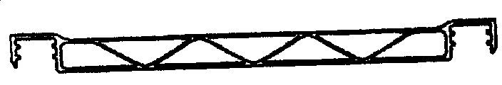
图2为本发明地铁车辆侧墙结构示意图。Fig. 2 is a schematic diagram of the structure of the side wall of the subway vehicle of the present invention.
图3为本发明地铁车辆侧墙实施例中第一种型材立柱截面示意图。Fig. 3 is a schematic cross-sectional view of the first profile column in the embodiment of the side wall of the subway vehicle of the present invention.
图4为本发明地铁车辆侧墙实施例中第二种型材立柱截面示意图。Fig. 4 is a schematic cross-sectional view of the second profile column in the embodiment of the side wall of the subway vehicle of the present invention.
图5为本发明地铁车辆侧墙实施例中第三种型材立柱截面示意图。Fig. 5 is a schematic cross-sectional view of the third profile column in the embodiment of the side wall of the subway vehicle of the present invention.
具体实施方式 Detailed ways
下面参照附图并结合实施例对本发明作进一步详细描述。但是本发明不限于所给出的例子。The present invention will be further described in detail below with reference to the accompanying drawings and examples. However, the invention is not limited to the examples given.
如图2所示,本发明地铁车辆侧墙,包括上边梁1、下边梁7以及车窗4,其特征是:具有以车门、车窗开口宽度为间距分布的型材立柱5,该型材立柱5的上、下端分别与上边梁1和下边梁7焊接成一体,相邻型材立柱间的车窗区具有分别与上边梁1和下边梁7铆接固定的窗上板8和窗下板9,车窗4玻璃位于窗上板8和窗下板9之间。As shown in Figure 2, the side wall of the subway vehicle of the present invention comprises upper side beam 1,
由于车厢两端处受力较小,为了使整车受力平衡,本发明进一步的特征是:在车厢两端采用截面相对较小的型材立柱。Since the force at both ends of the carriage is relatively small, in order to balance the stress on the whole vehicle, a further feature of the present invention is that profile columns with relatively small cross-sections are used at both ends of the carriage.
除上述实施例外,本发明还可以有其他实施方式。凡采用等同替换或等效变换形成的技术方案,均落在本发明要求的保护范围。In addition to the above-mentioned embodiments, the present invention can also have other implementations. All technical solutions formed by equivalent replacement or equivalent transformation fall within the scope of protection required by the present invention.
Claims (4)
Priority Applications (1)
| Application Number | Priority Date | Filing Date | Title |
|---|---|---|---|
| CNB2006100387310A CN100408403C (en) | 2006-03-09 | 2006-03-09 | Subway vehicle side wall |
Applications Claiming Priority (1)
| Application Number | Priority Date | Filing Date | Title |
|---|---|---|---|
| CNB2006100387310A CN100408403C (en) | 2006-03-09 | 2006-03-09 | Subway vehicle side wall |
Publications (2)
| Publication Number | Publication Date |
|---|---|
| CN101032966A CN101032966A (en) | 2007-09-12 |
| CN100408403C true CN100408403C (en) | 2008-08-06 |
Family
ID=38729755
Family Applications (1)
| Application Number | Title | Priority Date | Filing Date |
|---|---|---|---|
| CNB2006100387310A Expired - Lifetime CN100408403C (en) | 2006-03-09 | 2006-03-09 | Subway vehicle side wall |
Country Status (1)
| Country | Link |
|---|---|
| CN (1) | CN100408403C (en) |
Families Citing this family (6)
| Publication number | Priority date | Publication date | Assignee | Title |
|---|---|---|---|---|
| CN100564124C (en) * | 2008-06-26 | 2009-12-02 | 济南轨道交通装备有限责任公司 | The railway truck technical boundary beam |
| CN102887152B (en) * | 2011-07-22 | 2015-04-15 | 中国北车集团大同电力机车有限责任公司 | Car body and connecting device of side wall and under frame |
| CN103192839A (en) * | 2013-03-28 | 2013-07-10 | 唐山轨道客车有限责任公司 | Vehicle inner side wall |
| KR101812620B1 (en) * | 2013-09-04 | 2017-12-27 | 카와사키 주코교 카부시키 카이샤 | Railway vehicle body |
| CN110860815B (en) * | 2019-11-29 | 2022-04-12 | 安徽雷尔伟交通装备有限公司 | Novel aluminum alloy section tailor-welded side wall structure and assembly welding process thereof |
| CN116985859B (en) * | 2023-07-28 | 2025-10-17 | 中车株洲电力机车有限公司 | Vehicle body and rubber wheel train |
Citations (7)
| Publication number | Priority date | Publication date | Assignee | Title |
|---|---|---|---|---|
| US3999489A (en) * | 1974-12-18 | 1976-12-28 | Waggon Union Gmbh | Sliding wall arrangement for covered railroad freight cars |
| US4327648A (en) * | 1979-05-14 | 1982-05-04 | Frech Anton | Funicular railway car cabin |
| US5267515A (en) * | 1989-01-18 | 1993-12-07 | Hitachi, Ltd. | Vehicle body construction having longitudinally elongated extruded panels and continuous welds joining the panels |
| CN1136297A (en) * | 1994-09-30 | 1996-11-20 | Abb亨舍尔公开有限公司 | Tramway |
| CN1216958A (en) * | 1996-05-13 | 1999-05-19 | 杜瓦格公司 | carriages of rail vehicles |
| CN1101762C (en) * | 1997-12-22 | 2003-02-19 | 戴姆勒-克莱斯勒铁路系统有限公司 | locomotive car |
| CN2889816Y (en) * | 2006-03-09 | 2007-04-18 | 中国南车集团南京浦镇车辆厂 | Novel side wall of underground train |
-
2006
- 2006-03-09 CN CNB2006100387310A patent/CN100408403C/en not_active Expired - Lifetime
Patent Citations (7)
| Publication number | Priority date | Publication date | Assignee | Title |
|---|---|---|---|---|
| US3999489A (en) * | 1974-12-18 | 1976-12-28 | Waggon Union Gmbh | Sliding wall arrangement for covered railroad freight cars |
| US4327648A (en) * | 1979-05-14 | 1982-05-04 | Frech Anton | Funicular railway car cabin |
| US5267515A (en) * | 1989-01-18 | 1993-12-07 | Hitachi, Ltd. | Vehicle body construction having longitudinally elongated extruded panels and continuous welds joining the panels |
| CN1136297A (en) * | 1994-09-30 | 1996-11-20 | Abb亨舍尔公开有限公司 | Tramway |
| CN1216958A (en) * | 1996-05-13 | 1999-05-19 | 杜瓦格公司 | carriages of rail vehicles |
| CN1101762C (en) * | 1997-12-22 | 2003-02-19 | 戴姆勒-克莱斯勒铁路系统有限公司 | locomotive car |
| CN2889816Y (en) * | 2006-03-09 | 2007-04-18 | 中国南车集团南京浦镇车辆厂 | Novel side wall of underground train |
Non-Patent Citations (4)
| Title |
|---|
| 新干线车辆车体的强度和安全性评价. 公江等.国外铁道车辆,第40卷第6期. 2003 |
| 新干线车辆车体的强度和安全性评价. 公江等.国外铁道车辆,第40卷第6期. 2003 * |
| 铝合金车体结构设计构思. 常树民,马纪军.铁道车辆,第42卷第9期. 2004 |
| 铝合金车体结构设计构思. 常树民,马纪军.铁道车辆,第42卷第9期. 2004 * |
Also Published As
| Publication number | Publication date |
|---|---|
| CN101032966A (en) | 2007-09-12 |
Similar Documents
| Publication | Publication Date | Title |
|---|---|---|
| CN203681555U (en) | Car body structure of rail car | |
| CN101863290B (en) | Lightweight total-bearing body frame structure | |
| CN201189864Y (en) | Aluminum body | |
| CN202624228U (en) | Installation structure for rail vehicle cab framework and vehicle body | |
| CN103802849B (en) | A kind of Type B Body Structure for Metro Vehicle | |
| CN201907513U (en) | Stainless steel rail passenger train body | |
| CN102673585B (en) | The roof structure of car body of high speed railway car | |
| CN115771536B (en) | A vehicle body structure of a rail-type rubber-wheel rapid transit system | |
| CN106184245A (en) | A kind of lightweight body construction | |
| CN106428053B (en) | A kind of railroad coach steel structure of car body frame | |
| CN105197031A (en) | Rail car and side wall assembly thereof | |
| CN202448992U (en) | End wall for railway vehicle | |
| US20100213740A1 (en) | Vehicle and Container Body Structure Thereof | |
| CN110027577A (en) | Aluminum honeycomb and aluminium sheet splicing drivers' cab and the rail vehicle with it | |
| CN103072631A (en) | Combined A column and roof side rail of vehicle | |
| CN100408403C (en) | Subway vehicle side wall | |
| CN204915697U (en) | Rail vehicle and side wall subassembly thereof | |
| WO2019024424A1 (en) | Carriage sidewall framework unit, sidewall, and train carriage | |
| CN106143615B (en) | Lap joint type width-variable passenger car frame connecting structure | |
| CN103332201A (en) | Metro car roof structure without boundary beam | |
| CN201998996U (en) | Vehicle roof structure of high-speed railway vehicle body | |
| CN2889816Y (en) | Novel side wall of underground train | |
| CN104494622B (en) | Variable cross-section side wall for rail wagon | |
| CN205469076U (en) | Low -floor vehicle headwall | |
| CN113581230B (en) | Frameless aluminum honeycomb driver cab |
Legal Events
| Date | Code | Title | Description |
|---|---|---|---|
| C06 | Publication | ||
| PB01 | Publication | ||
| C10 | Entry into substantive examination | ||
| SE01 | Entry into force of request for substantive examination | ||
| C14 | Grant of patent or utility model | ||
| GR01 | Patent grant | ||
| ASS | Succession or assignment of patent right |
Owner name: NANCHE NANJING PUZHEN VEHICLE CO., LTD. Free format text: FORMER OWNER: CHINA SOUTHERN GROUP NANJING PUZHEN VEHICLE PLANT Effective date: 20080815 |
|
| C41 | Transfer of patent application or patent right or utility model | ||
| TR01 | Transfer of patent right |
Effective date of registration: 20080815 Address after: No. 68 Zhujiang North Road, Taishan Park, hi tech Development Zone, Jiangsu, Nanjing, China Patentee after: CSR NANJING PUZHEN Co.,Ltd. Address before: 5, dragon tiger lane, Nanjing Town, Jiangsu, China Patentee before: CSR NANJING PUZHEN ROLLING STO |
|
| C56 | Change in the name or address of the patentee | ||
| CP03 | Change of name, title or address |
Address after: 210031 Nanjing province high tech Development Zone, Taishan Park North Pearl Road, No. 68 Patentee after: CRRC NANJING PUZHEN Co.,Ltd. Address before: No. 68 Zhujiang North Road, Taishan Park, hi tech Development Zone, Jiangsu, Nanjing, China Patentee before: CSR NANJING PUZHEN Co.,Ltd. |
|
| CX01 | Expiry of patent term |
Granted publication date: 20080806 |
|
| CX01 | Expiry of patent term |