CN100382169C - Optical pickup and optical disc device - Google Patents

Optical pickup and optical disc device Download PDF

Info

Publication number
CN100382169C
CN100382169C CNB2005101276467A CN200510127646A CN100382169C CN 100382169 C CN100382169 C CN 100382169C CN B2005101276467 A CNB2005101276467 A CN B2005101276467A CN 200510127646 A CN200510127646 A CN 200510127646A CN 100382169 C CN100382169 C CN 100382169C
Authority
CN
China
Prior art keywords
light beam
light
aberration
object lens
correcting means
Prior art date
Legal status (The legal status is an assumption and is not a legal conclusion. Google has not performed a legal analysis and makes no representation as to the accuracy of the status listed.)
Expired - Fee Related
Application number
CNB2005101276467A
Other languages
Chinese (zh)
Other versions
CN1815582A (en
Inventor
山本健二
西纪彰
Current Assignee (The listed assignees may be inaccurate. Google has not performed a legal analysis and makes no representation or warranty as to the accuracy of the list.)
Sony Corp
Original Assignee
Sony Corp
Priority date (The priority date is an assumption and is not a legal conclusion. Google has not performed a legal analysis and makes no representation as to the accuracy of the date listed.)
Filing date
Publication date
Application filed by Sony Corp filed Critical Sony Corp
Publication of CN1815582A publication Critical patent/CN1815582A/en
Application granted granted Critical
Publication of CN100382169C publication Critical patent/CN100382169C/en
Anticipated expiration legal-status Critical
Expired - Fee Related legal-status Critical Current

Links

Images

Classifications

    • GPHYSICS
    • G11INFORMATION STORAGE
    • G11BINFORMATION STORAGE BASED ON RELATIVE MOVEMENT BETWEEN RECORD CARRIER AND TRANSDUCER
    • G11B7/00Recording or reproducing by optical means, e.g. recording using a thermal beam of optical radiation by modifying optical properties or the physical structure, reproducing using an optical beam at lower power by sensing optical properties; Record carriers therefor
    • G11B7/12Heads, e.g. forming of the optical beam spot or modulation of the optical beam
    • G11B7/135Means for guiding the beam from the source to the record carrier or from the record carrier to the detector
    • G11B7/1392Means for controlling the beam wavefront, e.g. for correction of aberration
    • GPHYSICS
    • G11INFORMATION STORAGE
    • G11BINFORMATION STORAGE BASED ON RELATIVE MOVEMENT BETWEEN RECORD CARRIER AND TRANSDUCER
    • G11B7/00Recording or reproducing by optical means, e.g. recording using a thermal beam of optical radiation by modifying optical properties or the physical structure, reproducing using an optical beam at lower power by sensing optical properties; Record carriers therefor
    • G11B7/12Heads, e.g. forming of the optical beam spot or modulation of the optical beam
    • G11B7/125Optical beam sources therefor, e.g. laser control circuitry specially adapted for optical storage devices; Modulators, e.g. means for controlling the size or intensity of optical spots or optical traces
    • G11B7/127Lasers; Multiple laser arrays
    • GPHYSICS
    • G11INFORMATION STORAGE
    • G11BINFORMATION STORAGE BASED ON RELATIVE MOVEMENT BETWEEN RECORD CARRIER AND TRANSDUCER
    • G11B7/00Recording or reproducing by optical means, e.g. recording using a thermal beam of optical radiation by modifying optical properties or the physical structure, reproducing using an optical beam at lower power by sensing optical properties; Record carriers therefor
    • G11B7/12Heads, e.g. forming of the optical beam spot or modulation of the optical beam
    • G11B7/135Means for guiding the beam from the source to the record carrier or from the record carrier to the detector
    • G11B7/1392Means for controlling the beam wavefront, e.g. for correction of aberration
    • G11B7/13922Means for controlling the beam wavefront, e.g. for correction of aberration passive
    • GPHYSICS
    • G11INFORMATION STORAGE
    • G11BINFORMATION STORAGE BASED ON RELATIVE MOVEMENT BETWEEN RECORD CARRIER AND TRANSDUCER
    • G11B7/00Recording or reproducing by optical means, e.g. recording using a thermal beam of optical radiation by modifying optical properties or the physical structure, reproducing using an optical beam at lower power by sensing optical properties; Record carriers therefor
    • G11B2007/0003Recording, reproducing or erasing systems characterised by the structure or type of the carrier
    • G11B2007/0006Recording, reproducing or erasing systems characterised by the structure or type of the carrier adapted for scanning different types of carrier, e.g. CD & DVD

Landscapes

  • Physics & Mathematics (AREA)
  • Optics & Photonics (AREA)
  • Optical Head (AREA)

Abstract

一种适用于多种不同类型的光盘的光学拾取器和光盘装置,其包括:光源,用于发射具有与第一光盘匹配的波长的第一光束或具有与第二光盘匹配的波长的第二光束;物镜,用于将从光源发射的第一光束或第二光束聚焦到第一光盘或第二光盘中合适的光盘的记录表面上;以及第一像差校正装置,其被布置在光源和物镜之间的第一光束的光路上,以生成像差来消除物镜导致的慧差。

An optical pickup and optical disc apparatus suitable for a plurality of different types of optical discs, comprising: a light source for emitting a first light beam having a wavelength matched to a first optical disc or a second light beam having a wavelength matched to a second optical disc a light beam; an objective lens for focusing a first light beam or a second light beam emitted from a light source onto a recording surface of an appropriate one of the first optical disc or the second optical disc; and a first aberration correcting device arranged between the light source and the second optical disc. On the optical path of the first beam between the objective lenses, aberrations are generated to eliminate the coma aberration caused by the objective lenses.

Description

光学拾取器和光盘装置 Optical pickup and optical disc device

技术领域 technical field

本发明涉及光学拾取器和光盘装置,光学拾取器可以方便地安装到光盘装置,光学拾取器可以将信息记录到多个不同类型的光盘中的任何一个和从多个不同类型的光盘中的任何一个再现信息。The present invention relates to an optical pickup and an optical disc device, the optical pickup can be easily mounted to the optical disc device, the optical pickup can record information to and from any of a plurality of different types of optical discs A reproduced message.

背景技术 Background technique

图1是相关技术中的安装在已知光盘装置上的光学拾取器,该光学拾取器利用3光束方法作为跟踪控制方法。FIG. 1 is an optical pickup mounted on a known optical disc device in the related art, which uses a 3-beam method as a tracking control method.

图1清楚地示出了光学拾取器101,其利用回放模式(replay mode)中的光栅103将从激光二极管102发射的光束L100划分成主光束和两个侧光束(下文中将总称为光束L200)。光束L200的一部分透过光束分光器104进入光电探测器106以检测所发射的光线的量,而光束L200的剩余部分被光束分光器104反射进入准直透镜105。Fig. 1 clearly shows an optical pickup 101, which utilizes a grating 103 in a playback mode (replay mode) to divide a beam L100 emitted from a laser diode 102 into a main beam and two side beams (hereinafter collectively referred to as beam L200) ). Part of the light beam L200 passes through the beam splitter 104 and enters the photodetector 106 to detect the amount of emitted light, while the remaining part of the light beam L200 is reflected by the beam splitter 104 and enters the collimating lens 105 .

准直透镜105将入射光束L200转换为准直光束,然后通过向上反射镜107使其照射1/4波片108。然后1/4波片108将入射光束L200转换为圆偏振光。然后,光束L200通过物镜109聚焦到光盘110的信息记录表面110A上。The collimating lens 105 converts the incident light beam L200 into a collimated light beam, and then makes it irradiate the 1/4 wave plate 108 through the upward reflecting mirror 107 . The 1/4 wave plate 108 then converts the incident light beam L200 into circularly polarized light. Then, the light beam L200 is focused onto the information recording surface 110A of the optical disc 110 by the objective lens 109 .

另一方面,由光盘110的信息记录表面110A反射的光束L200的部分(下文称作反射光束L300)通过物镜109进入1/4波片108,并且在其通过向上反射镜107进入到准直透镜105之前被1/4波片108转换为线偏振光。On the other hand, a part of the light beam L200 reflected by the information recording surface 110A of the optical disc 110 (hereinafter referred to as the reflected light beam L300) enters the 1/4 wave plate 108 through the objective lens 109, and enters the collimator lens through the upward reflection mirror 107 at it. 105 is converted into linearly polarized light by 1/4 wave plate 108 before.

然后,准直透镜105使入射的反射光束L300转换为聚焦光束,并且通过光束分光器104用该光束照射多透镜111。给入射的反射光束L300带来像散的多透镜111使入射的反射光束L300聚焦到光接收元件112的光接收表面112A上。Then, the collimator lens 105 converts the incident reflected beam L300 into a focused beam, and irradiates the multi-lens 111 with the beam through the beam splitter 104 . The multi-lens 111 that imparts astigmatism to the incident reflected light beam L300 focuses the incident reflected light beam L300 onto the light receiving surface 112A of the light receiving element 112 .

在上述布置中,光盘装置获取再现数据并且工作来根据各种信号进行跟踪控制和聚焦控制,这些信号包括根据入射到光接收元件112的光接收平面112A上的反射光束L300从光接收元件112输出的聚焦误差信号、跟踪误差信号和射频(RF)信号。In the above arrangement, the optical disc device acquires reproduced data and operates to perform tracking control and focus control based on various signals including output from the light receiving element 112 based on the reflected light beam L300 incident on the light receiving plane 112A of the light receiving element 112 focus error signal, tracking error signal and radio frequency (RF) signal.

已知的光盘装置具有表现出衍射透镜结构的物镜109的光学拾取器101,该光学拾取器101适于发射一般来自激光二极管102的光束L100并利用形成在物镜109上的衍射光栅使从光束L100生成的光束L200产生衍射,以将光束聚焦到光盘110的信息记录表面110A上,其中光束L100具有要与其一起使用的光盘110匹配的波长,这些光盘110是从不同类型的光盘中选出的,包括CD光盘(CD)和数字通用光盘(DVD),参考日本专利申请公开公布NO.10-199026。A known optical disc device has an optical pickup 101 exhibiting an objective lens 109 of a diffractive lens structure, which is adapted to emit a light beam L100 generally from a laser diode 102 and make the light beam L100 The generated light beam L200 is diffracted to focus the light beam on the information recording surface 110A of the optical disc 110, wherein the light beam L100 has a wavelength to be matched with the optical disc 110 to be used with it, and these optical discs 110 are selected from different types of optical discs, Including compact disc (CD) and digital versatile disc (DVD), refer to Japanese Patent Application Laid-Open Publication No. 10-199026.

发明内容 Contents of the invention

同时,近些年来,已开发出蓝光光盘(BD)来满足对更高记录密度和更大容量的需求。因此,需要这样的光盘装置,该光盘装置可以将信息记录到三种不同类型的光盘和再现来自这三种不同类型光盘的信息,其中这三种不同类型的光盘包括CD、DVD和BD。Meanwhile, in recent years, a Blu-ray Disc (BD) has been developed to meet demands for higher recording density and larger capacity. Therefore, there is a need for an optical disc device that can record information to and reproduce information from three different types of optical discs, including CDs, DVDs, and BDs.

但是,就保护衬底层的厚度和从光盘装置的激光二极管发射出的光线的波长来说,包括CD、DVD和BD这三种不同类型的光盘110彼此不同。更具体地说,CD的保护衬底层为1.2mm厚,DVD的为0.6mm厚,而BD的为0.1mm厚。从用于CD的激光二极管发射出的光束L100的波长为780nm,用于DVD的为650nm,而用于BD的为407nm。因此,必需对由于保护玻璃的厚度差和从光束L100产生的光束L200的波长差所导致的由光束产生的球差进行校正,并且将该光束聚焦到每个光盘110的信息记录表面110A上。However, three different types of optical discs 110 including CD, DVD, and BD are different from each other in terms of the thickness of the protective substrate layer and the wavelength of light emitted from the laser diode of the optical disc device. More specifically, the protective substrate layer is 1.2 mm thick for CDs, 0.6 mm thick for DVDs, and 0.1 mm thick for BDs. The wavelength of the light beam L100 emitted from the laser diode for CD is 780 nm, that for DVD is 650 nm, and that for BD is 407 nm. Therefore, it is necessary to correct the spherical aberration generated by the light beam due to the thickness difference of the cover glass and the wavelength difference of the light beam L200 generated from the light beam L100, and to focus the light beam on the information recording surface 110A of each optical disc 110.

现在,参考图2A到图2C,可以设想出通过下述方法来解决该问题:在物镜109的光接收表面109A一侧布置衍射元件111,以校正可归因于三种不同类型光盘110(包括CD、DVD和BD)的保护衬底层的厚度差的球差、以及可归因于光束L200的波长差的球差,然后将光束L200聚焦到各个光盘110的信息记录表面110A上。Now, referring to FIGS. 2A to 2C, it is conceivable to solve this problem by arranging a diffractive element 111 on the light receiving surface 109A side of the objective lens 109 to correct CD, DVD, and BD) the spherical aberration of the thickness difference of the protective substrate layer and the spherical aberration attributable to the wavelength difference of the light beam L200, and then focus the light beam L200 onto the information recording surface 110A of each optical disc 110.

但是,设计既可以校正归因于三种不同类型光盘110(包括CD、DVD和BD)的保护衬底层的厚度差的球差、也可以校正可归因于光束L200的波长差的球差的衍射元件111是极其困难的。例如,如果针对三种类型光盘110之一的保护衬底层的厚度和相应的光束L200的波长优化衍射效率,则对于剩余的两种类型的光盘110的保护衬底层的厚度和相应的光束L200就不是优化的了,因此降低了剩余的两种类型光盘110的记录/再现特性。However, the design can correct both the spherical aberration attributable to the thickness difference of the protective substrate layer of the three different types of optical discs 110 (including CD, DVD, and BD) and the spherical aberration attributable to the wavelength difference of the light beam L200. Diffractive elements 111 are extremely difficult. For example, if the diffraction efficiency is optimized for the thickness of the protective substrate layer and the wavelength of the corresponding light beam L200 for one of the three types of optical discs 110, then the thickness of the protective substrate layer and the corresponding light beam L200 for the remaining two types of optical discs 110 will be It is not optimized anymore, thus degrading the recording/reproducing characteristics of the remaining two types of optical discs 110 .

如图3A所示,在三种不同类型的光盘110中的CD的CD回放模式中,通过使用发散光的光束L201(包括功率成份)替换照射物镜109的准直光束L200,可以解决这个问题。利用这种技术,在驱动光盘110中的CD以再现信息时,通过利用发散光束而不是利用衍射元件111的衍射效果,可归因于保护衬底层的厚度差的球差以及可归因于波长差的球差得到了校正。另一方面,在驱动三种不同类型的光盘110中的DVD或BD来再现信息时,利用衍射元件111校正球差并且提高了衍射效率。As shown in FIG. 3A, this problem can be solved by replacing the collimated light beam L200 illuminating the objective lens 109 with the light beam L201 of divergent light (including power component) in the CD playback mode of CD among three different types of optical discs 110. With this technique, when driving a CD in the optical disc 110 to reproduce information, by using a diverging beam instead of using the diffraction effect of the diffraction element 111, the spherical aberration attributable to the thickness difference of the protective substrate layer and the spherical aberration attributable to the wavelength Poor spherical aberration is corrected. On the other hand, when reproducing information by driving DVD or BD among the three different types of optical discs 110 , the spherical aberration is corrected by the diffraction element 111 and diffraction efficiency is improved.

但是,利用这种技术,在通过驱动物镜109进行跟踪操作而使发散光的光束L201倾斜进入物镜109时,缩小了发散光的光束L201的有限的放大率,如图3B所示。然后,由于跟踪操作导致产生不允许的慧差,结果,由于在光盘110的信息记录表面110A上光斑的变形的剖面,导致三种不同类型的光盘110中的CD的记录/再现特性降低。However, with this technique, when the divergent light beam L201 obliquely enters the objective lens 109 by driving the objective lens 109 for tracking operation, the finite magnification of the divergent light beam L201 is reduced, as shown in FIG. 3B . Then, unacceptable coma aberration is generated due to the tracking operation, and as a result, the recording/reproducing characteristics of the CDs in the three different types of optical discs 110 are degraded due to the deformed profile of the light spot on the information recording surface 110A of the optical disc 110.

考虑上述情形,因此本发明的目的是提供能够改善多种不同类型的光盘的记录/再现特性的光学拾取器和光盘装置。In consideration of the above circumstances, it is therefore an object of the present invention to provide an optical pickup and an optical disc device capable of improving recording/reproducing characteristics of various types of optical discs.

在本发明的一个方面中,通过提供一种适用于多种不同类型光盘的光学拾取器实现本发明的上述和其他目的,该光学拾取器包括:光源,用于发射具有与第一光盘匹配的波长的第一光束或具有与第二光盘匹配的波长的第二光束;物镜,用于将从光源发射的第一光束或第二光束聚焦到第一光盘或第二光盘中合适的光盘的记录表面上;第一像差校正装置,其被布置在光源和物镜之间的第一光束的光路上,以产生用于消除物镜导致的慧差的像差;和载运装置,用于载运所述第一像差校正装置,以在使用所述第一光盘用于记录/再现时,将所述第一像差校正装置插入到所述光源和所述物镜之间的所述第一光束和所述第二光束的所述光路中,在使用所述第二光盘用于记录/再现时,将所述第一像差校正装置从所述光源和所述物镜之间的所述第一光束和所述第二光束的所述光路中拉出。In one aspect of the present invention, the above and other objects of the present invention are achieved by providing an optical pickup suitable for a plurality of different types of optical discs, the optical pickup comprising: a light source for emitting a first light beam of a wavelength or a second light beam having a wavelength matched to that of the second optical disc; an objective lens for focusing the first light beam or the second light beam emitted from the light source to an appropriate one of the first optical disc or the second optical disc for recording On the surface; a first aberration correcting device, which is arranged on the optical path of the first light beam between the light source and the objective lens, to generate an aberration for eliminating coma aberration caused by the objective lens; and carrying means for carrying the first aberration correcting means to insert the first light beam and the first aberration correcting means between the light source and the objective lens when using the first optical disc for recording/reproducing In the optical path of the second light beam, when using the second optical disc for recording/reproduction, the first aberration correcting device is separated from the first light beam and the light source between the light source and the objective lens The second light beam is pulled out of the optical path.

在本发明的另一个方面中,提供了一种适用于多种不同类型光盘的光学拾取器,其中多种不同类型的光盘表现出用于接收光束的透明衬底的不同厚度,该光学拾取器包括:光源,用于有选择地发射具有与第一光盘匹配的波长的第一光束或具有与第二光盘匹配的波长的第二光束;物镜,用于将从光源发射的第一光束或第二光束聚焦到第一光盘或第二光盘中合适的光盘的记录表面上;第一像差校正装置,其被布置在光源和物镜之间的第一光束的光路上,以产生用于消除物镜导致的慧差的像差;载运装置,用于载运所述第一像差校正装置,以在使用所述第一光盘用于记录/再现时,将所述第一像差校正装置插入到所述光源和所述物镜之间的所述第一光束和所述第二光束的所述光路中,在使用所述第二光盘用于记录/再现时,将所述第一像差校正装置从所述光源和所述物镜之间的所述第一光束和所述第二光束的所述光路中拉出;并且第一像差校正装置使从光源发射的第一光束从准直光转换为具有第一像差校正装置剖面并且包含功率成份的波前。In another aspect of the present invention, there is provided an optical pickup suitable for a plurality of different types of optical discs exhibiting different thicknesses of transparent substrates for receiving light beams, the optical pickup Including: a light source for selectively emitting a first light beam having a wavelength matched with the first optical disc or a second light beam having a wavelength matched with the second optical disc; an objective lens for transmitting the first light beam emitted from the light source or the second light beam The two light beams are focused onto the recording surface of a suitable optical disc in the first optical disc or the second optical disc; a first aberration correcting device, which is arranged on the optical path of the first light beam between the light source and the objective lens, to produce an optical disc for eliminating the objective lens aberration caused by coma; carrying means for carrying the first aberration correcting device to insert the first aberration correcting device into the In the optical path of the first light beam and the second light beam between the light source and the objective lens, when using the second optical disc for recording/reproduction, the first aberration correcting device is removed from The first light beam and the second light beam between the light source and the objective lens are pulled out from the optical path; and the first aberration correcting means converts the first light beam emitted from the light source from collimated light to A wavefront having a first aberration correcting device profile and including a power component.

在本发明的又一个方面中,提供了一种装备有适用于操作多种不同类型光盘的光学拾取器的光盘装置,该装置包括:光源,用于发射具有与第一光盘匹配的波长的第一光束或具有与第二光盘匹配的波长的第二光束;物镜,用于将从光源发射的第一光束或第二光束聚焦到第一光盘或第二光盘中合适的光盘的记录表面上;第一像差校正装置,其被布置在光源和物镜之间的第一光束的光路上,以产生用于消除物镜导致的慧差的像差;和载运装置,用于载运所述第一像差校正装置,以在使用所述第一光盘用于记录/再现时,将所述第一像差校正装置插入到所述光源和所述物镜之间的所述第一光束和所述第二光束的所述光路中,在使用所述第二光盘用于记录/再现时,将所述第一像差校正装置从所述光源和所述物镜之间的所述第一光束和所述第二光束的所述光路中拉出。In yet another aspect of the present invention, there is provided an optical disc device equipped with an optical pickup suitable for handling a plurality of different types of optical discs, the device comprising: a light source for emitting a first optical disc having a wavelength matched to the first optical disc a light beam or a second light beam having a wavelength matched to the second optical disc; an objective lens for focusing the first light beam or the second light beam emitted from the light source onto a recording surface of a suitable one of the first optical disc or the second optical disc; A first aberration correcting device arranged on the optical path of the first light beam between the light source and the objective lens to generate an aberration for eliminating coma aberration caused by the objective lens; and a carrying device for carrying the first image aberration correcting means for inserting the first aberration correcting means between the first light beam and the second light beam between the light source and the objective lens when the first optical disc is used for recording/reproducing In the optical path of the light beam, when the second optical disc is used for recording/reproducing, the first aberration correcting device is separated from the first light beam and the second light beam between the light source and the objective lens. Two beams are pulled out of the optical path.

因此,根据本发明的适用于多种不同类型的光盘的光学拾取器包括:光源,用于发射具有与第一光盘匹配的波长的第一光束或具有与第二光盘匹配的波长的第二光束;物镜,用于将从光源发射的第一光束或第二光束聚焦到第一光盘或第二光盘中合适的光盘的记录表面上;第一像差校正单元,其被布置在光源和物镜之间的第一光束的光路上,以产生用于消除物镜导致的慧差的像差;和载运装置,用于载运所述第一像差校正单元,以在使用所述第一光盘用于记录/再现时,将所述第一像差校正单元插入到所述光源和所述物镜之间的所述第一光束和所述第二光束的所述光路中,在使用所述第二光盘用于记录/再现时,将所述第一像差校正单元从所述光源和所述物镜之间的所述第一光束和所述第二光束的所述光路中拉出。然后,第一光束通过第一像差校正单元和物镜聚焦到第一光盘上,而第二光束通过物镜聚焦到第二光盘上,以使得如果包括多种不同类型的光盘,则可以恒定地将光束聚焦到聚焦光斑的衍射极限。因此,根据本发明,可以实现能够改善多种不同类型光盘的记录/再现特性的光盘拾取器。Therefore, an optical pickup suitable for a plurality of different types of optical discs according to the present invention includes: a light source for emitting a first light beam having a wavelength matched to a first optical disc or a second light beam having a wavelength matched to a second optical disc an objective lens for focusing the first light beam or the second light beam emitted from the light source onto the recording surface of a suitable one of the first optical disc or the second optical disc; a first aberration correction unit arranged between the light source and the objective lens on the optical path of the first light beam between them, to generate aberrations for eliminating coma aberration caused by the objective lens; and a carrying device for carrying the first aberration correction unit for recording when using the first optical disc /When reproducing, inserting the first aberration correcting unit into the optical path of the first light beam and the second light beam between the light source and the objective lens, when using the second optical disc At the time of recording/reproducing, the first aberration correcting unit is pulled out from the optical path of the first light beam and the second light beam between the light source and the objective lens. Then, the first light beam is focused on the first optical disc through the first aberration correction unit and the objective lens, and the second light beam is focused on the second optical disc through the objective lens, so that if a plurality of different types of optical discs are included, the The beam is focused to the diffraction limit of the focused spot. Therefore, according to the present invention, it is possible to realize an optical disc pickup capable of improving recording/reproducing characteristics of various types of optical discs.

类似地,根据本发明的装备有适用于多种不同类型光盘的光学拾取器的光盘装置包括:光源,用于发射具有与第一光盘匹配的波长的第一光束或具有与第二光盘匹配的波长的第二光束;物镜,用于将从光源发射的第一光束或第二光束聚焦到第一光盘或第二光盘中合适的光盘的记录表面上;第一像差校正单元,其被布置在光源和物镜之间的第一光束的光路上,以生成用于消除物镜导致的慧差的像差;和载运装置,用于载运所述第一像差校正单元,以在使用所述第一光盘用于记录/再现时,将所述第一像差校正单元插入到所述光源和所述物镜之间的所述第一光束和所述第二光束的所述光路中,在使用所述第二光盘用于记录/再现时,将所述第一像差校正单元从所述光源和所述物镜之间的所述第一光束和所述第二光束的所述光路中拉出。然后,第一光束通过第一像差校正单元和物镜聚焦到第一光盘上,而第二光束通过物镜聚焦到第二光盘上,使得如果包括多种不同类型的光盘,则光束可以恒定地被聚焦到聚焦光斑的衍射极限。因此,根据本发明,可以实现能够改善多种不同类型光盘的记录/再现特性的光盘装置。Similarly, an optical disc device equipped with an optical pickup suitable for a plurality of different types of optical discs according to the present invention includes a light source for emitting a first light beam having a wavelength matched to a first optical disc or having a wavelength matched to a second optical disc. a wavelength of the second light beam; an objective lens for focusing the first light beam or the second light beam emitted from the light source onto a recording surface of an appropriate one of the first optical disc or the second optical disc; a first aberration correction unit arranged on the optical path of the first light beam between the light source and the objective lens to generate aberration for eliminating coma aberration caused by the objective lens; and a carrying device for carrying the first aberration correction unit to use the first When an optical disc is used for recording/reproducing, the first aberration correcting unit is inserted into the optical path of the first light beam and the second light beam between the light source and the objective lens, when using the When the second optical disc is used for recording/reproducing, the first aberration correction unit is pulled out from the optical path of the first light beam and the second light beam between the light source and the objective lens. Then, the first light beam is focused onto the first optical disc through the first aberration correcting unit and the objective lens, and the second light beam is focused onto the second optical disc through the objective lens, so that if a plurality of different types of optical discs are included, the light beam can be constantly Focus to the diffraction limit of the focused spot. Therefore, according to the present invention, it is possible to realize an optical disc device capable of improving recording/reproducing characteristics of various types of optical discs.

在结合附图阅读时,本发明的本质、原理和用途将从下面的详细描述变清楚,在附图中,相似的部分用相似的标号或符号表示。The nature, principles and uses of the present invention will become apparent from the following detailed description when read in conjunction with the accompanying drawings, in which like parts are indicated by like numerals or symbols.

附图说明 Description of drawings

在附图中:In the attached picture:

图1是已知光学拾取器的示意性图示,其示出了该光学拾取器的配置;Fig. 1 is a schematic illustration of a known optical pickup, which shows the configuration of the optical pickup;

图2A到图2C是已知光学拾取器的示意性图示,其比图1更具体地示出了光学拾取器的配置;2A to 2C are schematic illustrations of a known optical pickup, which show the configuration of the optical pickup more specifically than FIG. 1;

图3A和图3B是由于已知光学拾取器的跟踪操作所导致的慧差的示意性图示;3A and 3B are schematic illustrations of coma aberration due to the tracking operation of a known optical pickup;

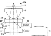
图4是根据本发明的光学拾取器的实施例的示意性图示,其示出了该光学拾取器的配置;FIG. 4 is a schematic illustration of an embodiment of an optical pickup according to the present invention, showing the configuration of the optical pickup;

图5是在CD回放模式中插入和移除图4的实施例的像场校正透镜的示意性图示;Figure 5 is a schematic illustration of insertion and removal of the field correction lens of the embodiment of Figure 4 in CD playback mode;

图6A和图6B是图4的实施例的像差校正元件的示意性图示,其示出了该像差校正元件的具体配置;6A and FIG. 6B are schematic illustrations of the aberration correction element of the embodiment of FIG. 4, which show a specific configuration of the aberration correction element;

图7是图4的实施例的像差校正元件的示意性图示,其示出了该像差校正元件的具体配置;7 is a schematic illustration of the aberration correction element of the embodiment of FIG. 4, which shows a specific configuration of the aberration correction element;

图8是图4的实施例的像场校正透镜、物镜和CD保护玻璃(coverglass)的示意性图示,其示出了它们的具体配置;Figure 8 is a schematic illustration of the field correction lens, objective lens and CD coverglass (coverglass) of the embodiment of Figure 4, which shows their specific configurations;

图9是图示出了图4的实施例的场圆(field turn)和像差之间的关系的图表;Figure 9 is a graph illustrating the relationship between field turn and aberration of the embodiment of Figure 4;

图10是图示出了已知光学拾取器的场圆和像差之间的关系的图表;10 is a graph illustrating the relationship between field circle and aberration of a known optical pickup;

图11是在DVD回放模式中插入和移除图4的实施例的像场校正透镜的示意性图示;11 is a schematic illustration of insertion and removal of the field correction lens of the embodiment of FIG. 4 in DVD playback mode;

图12是在BD回放模式中插入和移除图4的实施例的像场校正透镜的示意性图示;FIG. 12 is a schematic illustration of insertion and removal of the field correction lens of the embodiment of FIG. 4 in BD playback mode;

图13是根据本发明的光盘装置的实施例的示意性图示,其示出了该光盘装置的配置;13 is a schematic illustration of an embodiment of an optical disc device according to the present invention, showing the configuration of the optical disc device;

图14是插入和移除图13的实施例的像场校正透镜的示意性图示;Figure 14 is a schematic illustration of insertion and removal of the field correction lens of the embodiment of Figure 13;

图15是在图13的实施例的像场校正透镜和放大转换元件之间切换的示意性图示;以及Figure 15 is a schematic illustration of switching between the field correction lens and the magnification conversion element of the embodiment of Figure 13; and

图16是在图13的实施例的像场校正透镜和放大转换元件之间切换的示意性图示。16 is a schematic illustration of switching between the field correction lens and the magnification conversion element of the embodiment of FIG. 13 .

具体实施方式 Detailed ways

现在,将参考图示本发明优选实施例的附图更详细地描述本发明。Now, the present invention will be described in more detail with reference to the accompanying drawings that illustrate preferred embodiments of the invention.

(1)本实施例的光学拾取器的配置(1) Configuration of the optical pickup of the present embodiment

参考图4,标号20概括表示本实施例的光学拾取器,其包括激光二极管2、向上反射镜7和物镜9等,其中激光二极管2发射光束L1,光束L1具有与要与本实施例一起使用的三种不同类型的光盘中的任何一种匹配的波长,这些光盘可以是CD、DVD或BD。另外,作为第一像差校正装置工作的像场校正透镜21和作为第二像差校正装置工作的像差校正元件22布置在向上反射镜7和物镜9之间。此外,还提供了用于可移除地插入像场校正透镜21的载运机构23。三种不同类型的光盘的保护衬底层的厚度彼此不同。更具体地说,CD的保护衬底层为1.2mm厚,DVD的为0.6mm厚,而BD的为0.1mm厚。With reference to Fig. 4, reference numeral 20 generally represents the optical pick-up of present embodiment, and it comprises laser diode 2, upward reflection mirror 7 and object lens 9 etc., wherein laser diode 2 emits light beam L1, light beam L1 has and will use together with present embodiment Matching wavelengths to any of three different types of discs, which can be CDs, DVDs, or BDs. In addition, a field correction lens 21 operating as a first aberration correcting means and an aberration correcting element 22 operating as a second aberration correcting means are arranged between the upward reflection mirror 7 and the objective lens 9 . Furthermore, a carrier mechanism 23 for removably inserting the field correction lens 21 is also provided. The thicknesses of the protective substrate layers of the three different types of optical discs were different from each other. More specifically, the protective substrate layer is 1.2 mm thick for CDs, 0.6 mm thick for DVDs, and 0.1 mm thick for BDs.

参考图5,更具体地说,在用于回放CD的CD回放模式中,从激光二极管2发射出的具有与该CD匹配的波长(780nm)的光束L1通过光栅透镜3被划分为主光束和两个侧光束(在下文中总地简称为光束L2),并且然后被准直。然后,准直光束L2通过光束分光器4、准直透镜5、向上反射镜7和1/4波片8进入像场校正透镜21。Referring to FIG. 5, more specifically, in the CD playback mode for playing back a CD, a light beam L1 emitted from a laser diode 2 having a wavelength (780 nm) matched to the CD is divided into a main beam and a light beam by a grating lens 3. Two side beams (hereinafter referred to collectively as beam L2) are then collimated. Then, the collimated light beam L2 enters the image field correction lens 21 through the beam splitter 4 , the collimator lens 5 , the upward reflection mirror 7 and the 1/4 wave plate 8 .

如图5所示,使用透明基体构件形成像场校正透镜21,该透明基体构件一般由玻璃制成,并且具有表现为预定曲线状剖面的光接收表面21A和平面光发射表面21B,以作为非球面透镜工作。As shown in FIG. 5, the field correction lens 21 is formed using a transparent base member generally made of glass and having a light-receiving surface 21A and a planar light-emitting surface 21B exhibiting a predetermined curved profile as a non-conductive lens. Spherical lenses work.

利用这种布置,像场校正透镜21使入射光束L2从准直光转换为根据像场校正透镜21的曲线状剖面的发散光(具有像场校正透镜21的曲线状剖面并且包含功率成份的波前),并且将其发射到像差校正元件22。这样,利用该发散光束,校正了可归因于光盘10之间的保护衬底层的厚度差的球差和可归因于波长差的球差。With this arrangement, the field correction lens 21 converts the incident light beam L2 from collimated light into divergent light according to the curved section of the field correction lens 21 (waveform having the curved section of the field correction lens 21 and containing power components front), and transmit it to the aberration correcting element 22. Thus, with the diverging beam, spherical aberration attributable to the difference in thickness of the protective substrate layer between the optical discs 10 and spherical aberration attributable to the difference in wavelength are corrected.

如图5所示,使用透明基体构件形成像差校正元件22,该透明基体构件一般由玻璃制成,并且具有光接收表面22A和光发射表面22B,这两个表面都是平面。As shown in FIG. 5 , the aberration correcting element 22 is formed using a transparent base member generally made of glass and having a light receiving surface 22A and a light emitting surface 22B, both of which are flat.

现在参考图6,像差校正元件22的光接收表面22A由同心铺设的圆形衍射元件24形成,这些圆形衍射元件24一个在另一个上面,并且每个都具有预定的波长选择属性,这使它们表现出各自的高度。例如,它们中的一个透射具有适于BD的波长(407nm)的光束L2和具有适于CD的波长的光束L2而不使它们衍射,但是使具有适于DVD的波长(680nm)的光束L2衍射。因此,利用这种布置,例如在回放三种不同类型的光盘10中的CD或BD中合适的光盘的CD回放模式或BD回放模式中,与用于将光束L2从准直光转换为衍射光并将其聚焦到光盘10的信息记录表面10A上的布置相比,都可以在不使用衍射的情况下使光束L2以更大量的光线聚焦到光盘10的信息记录表面10A上。Referring now to FIG. 6, the light-receiving surface 22A of the aberration correcting element 22 is formed by concentrically laying circular diffractive elements 24 one above the other and each having a predetermined wavelength selection property, which make them show their respective heights. For example, one of them transmits light beam L2 having a wavelength suitable for BD (407 nm) and light beam L2 having a wavelength suitable for CD without diffracting them, but diffracts light beam L2 having a wavelength suitable for DVD (680 nm) . Therefore, with this arrangement, for example, in a CD playback mode or a BD playback mode in which an appropriate disc among CDs or BDs among the three different types of optical discs 10 is played back, the same as for converting the light beam L2 from collimated light to diffracted light and focusing it on the information recording surface 10A of the optical disc 10, it is possible to focus the light beam L2 on the information recording surface 10A of the optical disc 10 with a larger amount of rays without using diffraction.

因此,利用这种布置,像差校正元件22仅在具有适于DVD的波长的光束L2透过衍射元件24时使其衍射,以相对应物镜9对具有适于DVD的波长的光束L2的球差进行校正。Therefore, with this arrangement, the aberration correcting element 22 diffracts the light beam L2 having the wavelength suitable for DVD only when it is transmitted through the diffractive element 24, so as to correspond to the spherical shape of the light beam L2 having the wavelength suitable for DVD by the objective lens 9. The difference is corrected.

另外,如图7所示,每个具有预定波长选择属性的用于多个不同波长的波长滤波薄膜25被镀到像差校正元件22的光发射表面22B。In addition, as shown in FIG. 7 , wavelength filter films 25 for a plurality of different wavelengths each having a predetermined wavelength selection property are plated to the light emitting surface 22B of the aberration correcting element 22 .

波长滤波薄膜25一般以下述方式布置。第一波长滤波薄膜25A被布置在将物镜9的数值孔径限定为等于0.45的中心圆区域25D的外侧并且在将物镜9的数值孔径限定为等于0.6的圆区域的内部,使得基本上全透射具有适于DVD的波长的光束L2和具有适于BD的波长的光束,但是基本上全反射具有适于CD的波长的光束L2;第二波长滤波薄膜25B被布置在将物镜9的数值孔径限定为等于0.6的圆区域的外侧并且将物镜9的数值孔径限定为等于0.85的圆区域的内部,使得基本上全透射具有适于BD的波长的光束L2,但是基本上全反射具有适于DVD的波长的光束L2和具有适于CD的波长的光束L2;而第三波长滤波薄膜25C被布置在将物镜9的数值孔径限定为等于0.85的圆区域的外侧,使得基本上全反射具有适于BD的波长的光束L2、具有适于DVD的波长的光束L2和具有适于CD的波长的光束L2。The wavelength filtering film 25 is generally arranged in the following manner. The first wavelength filter film 25A is arranged outside the central circular region 25D defining the numerical aperture of the objective lens 9 equal to 0.45 and inside the circular region defining the numerical aperture of the objective lens 9 equal to 0.6 so that substantially total transmission has The light beam L2 with a wavelength suitable for DVD and the light beam with a wavelength suitable for BD, but the light beam L2 with a wavelength suitable for CD is substantially totally reflected; the second wavelength filter film 25B is arranged to limit the numerical aperture of the objective lens 9 to The outside of the circular area equal to 0.6 and the numerical aperture of the objective lens 9 is defined to be equal to the inside of the circular area of 0.85, so that the light beam L2 with a wavelength suitable for BD is substantially completely transmitted, but substantially totally reflected with a wavelength suitable for DVD and the light beam L2 having a wavelength suitable for CD; and the third wavelength filter film 25C is arranged outside the circular area that limits the numerical aperture of the objective lens 9 to be equal to 0.85, so that substantially total reflection has a suitable for BD The light beam L2 having a wavelength suitable for DVD, the light beam L2 having a wavelength suitable for DVD, and the light beam L2 having a wavelength suitable for CD.

利用这种布置,像差校正元件22可以选择具有适于BD的波长的光束作为匹配0.85数值孔径的光束L2以及具有适于DVD的波长的光束作为匹配0.6数值孔径的光束L2,同时其可以选择具有适于CD的波长的光束作为匹配0.45数值孔径的光束L2。With this arrangement, the aberration correcting element 22 can select a beam having a wavelength suitable for BD as a beam L2 matching a 0.85 numerical aperture and a beam having a wavelength suitable for a DVD as a beam L2 matching a 0.6 numerical aperture, while it can select A light beam having a wavelength suitable for CD is used as a light beam L2 matching a numerical aperture of 0.45.

这样,光学拾取器20将入射到像场校正透镜21的具有适于CD的波长的光束L2从准直光转换为发散光以校正可归因于保护衬底层的厚度差的球差和可归因于波长差的球差,并且将其发射到像差校正元件22。然后,其限制发散光束L2进入像差校正元件22的孔径以便使其匹配0.45数值孔径,然后利用物镜9将该光束聚焦到光盘10的信息记录表面10A上。In this way, the optical pickup 20 converts the light beam L2 having a wavelength suitable for CD incident on the field correction lens 21 from collimated light to divergent light to correct spherical aberration and attributable The spherical aberration due to the wavelength difference is emitted to the aberration correcting element 22 . Then, it restricts the divergent light beam L2 from entering the aperture of the aberration correcting element 22 so as to match the numerical aperture of 0.45, and then focuses the light beam onto the information recording surface 10A of the optical disc 10 with the objective lens 9 .

注意,像场校正透镜21的曲线状剖面被限定为使得没有相对于CD的像差,其中CD是三种不同类型的光盘10之一。Note that the curved section of the field correction lens 21 is defined so that there is no aberration with respect to CD, which is one of three different types of optical discs 10 .

因此,由于通过像场校正透镜21、像差校正元件22和物镜9,具有适于CD的波长的光束L2被聚焦到光盘10的信息记录表面10A上,所以光学拾取器20可以在信息记录表面10A上将聚焦光斑聚焦到衍射极限。Therefore, since the light beam L2 having a wavelength suitable for CD is focused onto the information recording surface 10A of the optical disc 10 through the field correction lens 21, the aberration correction element 22, and the objective lens 9, the optical pickup 20 can operate on the information recording surface. The focused spot on the 10A is focused to the diffraction limit.

随后,在使由CD或光盘10反射的反射光束L3通过物镜9和像差校正元件22进入像场校正透镜21之后,与在上述回放模式的情形中一样,通过1/4波片8、向上反射镜7、准直透镜5、光束分光器4和多透镜11,光学拾取器20将光束L3聚焦到光接收元件12的光接收表面12A上。Subsequently, after the reflected light beam L3 reflected by the CD or optical disc 10 enters the field correction lens 21 through the objective lens 9 and the aberration correcting element 22, as in the case of the playback mode described above, passes through the 1/4 wave plate 8, upward Mirror 7 , collimator lens 5 , beam splitter 4 and multi-lens 11 , optical pickup 20 focus light beam L3 onto light receiving surface 12A of light receiving element 12 .

另外,在CD回放模式中,光学拾取器20校正在跟踪操作中引起的慧差,在跟踪操作中,物镜9在光盘10的径向方向上平行于光盘10的记录表面移动。In addition, in the CD playback mode, the optical pickup 20 corrects coma aberration caused in a tracking operation in which the objective lens 9 moves parallel to the recording surface of the optical disc 10 in the radial direction of the optical disc 10 .

更具体地说,在物镜9的视像场被驱动来作出移动物镜9的跟踪操作时,在移动物镜9的跟踪操作中,光学拾取器20校正由于倾斜进入物镜9的光束L2所导致的慧差,这是由于该慧差被由于像场校正透镜21和物镜9的光轴偏心所导致的慧差所抵消。More specifically, when the field of view of the objective lens 9 is driven to make a tracking operation of moving the objective lens 9, in the tracking operation of moving the objective lens 9, the optical pickup 20 corrects the coma caused by the light beam L2 obliquely entering the objective lens 9. This is because the coma aberration is canceled by the coma aberration caused by the decentering of the optical axes of the field correction lens 21 and the objective lens 9 .

因此,即使在倾斜进入物镜9的光束L2被聚焦到光盘10的信息记录表面10A上时,光学拾取器20也可以在消除了慧差的状态中在信息记录表面10A上将光斑聚焦到衍射极限。Therefore, even when the light beam L2 obliquely entering the objective lens 9 is focused on the information recording surface 10A of the optical disc 10, the optical pickup 20 can focus the light spot to the diffraction limit on the information recording surface 10A in a state where the coma aberration is canceled .

至于像场校正透镜21的曲线状剖面,如果光轴的高度为Y mm,曲率半径为R mm、锥形常数(conical constant)为K,并且Y4项、Y6项、Y8项、Y10项、Y12项、Y14项和Y16项的非球面系数分别为A、B、C、D、E、F和G,则从表面顶点的深度X mm由下面所示非球面方程(1)给出。因此,可以使用下述公式设计像场校正透镜21的非球面剖面。As for the curved section of the field correction lens 21, if the height of the optical axis is Y mm, the radius of curvature is R mm, the conical constant is K, and Y 4 terms, Y 6 terms, Y 8 terms, Y The aspheric coefficients of 10 items, Y 12 items, Y 14 items and Y 16 items are A, B, C, D, E, F and G respectively, then the depth X mm from the surface vertex is given by the aspheric surface equation shown below ( 1) Give. Therefore, the aspherical profile of the field correction lens 21 can be designed using the following formula.

X=Y2/R/1+{1-(1+k)(Y/R)2}1/2+AY4+BY6+CY8+DY10+EY12+FY14+GY16…(1)X=Y 2 /R/1+{1-(1+k)(Y/R) 2 } 1/2 +AY 4 +BY 6 +CY 8 +DY 10 +EY 12 +FY 14 +GY 16 …( 1)

图8示出了像场校正透镜21的光接收表面21A的剖面、光发射表面21B的剖面、曲率半径、到下一个表面的轴上厚度、对于具有适于CD的波长的光束L2的折射率和针对具有适合于CD的波长的光束L2的非球面常量,以及物镜9的对应参数。8 shows a section of the light-receiving surface 21A of the field correction lens 21, a section of the light-emitting surface 21B, a radius of curvature, an axial thickness to the next surface, and a refractive index for a light beam L2 having a wavelength suitable for CD. and the aspheric constants for the light beam L2 having a wavelength suitable for CD, and the corresponding parameters of the objective lens 9 .

图9示出了在以图8中列出的方式设计像场校正透镜21、物镜9和光盘10(其是CD)时相对于物镜9的场圆的球差、慧差和像散。另一方面,图10示出了在下述情况时相对于物镜9的场圆的球差、慧差和像散,所述情况是在激光二极管2的发光点与物镜9隔开22.82mm并且发散光的光束L2在如图3所示没有插入像场校正透镜21的情况下进入物镜9时。FIG. 9 shows spherical aberration, coma and astigmatism with respect to the field circle of the objective lens 9 when the field correction lens 21, the objective lens 9, and the optical disc 10 (which is a CD) are designed in the manner listed in FIG. On the other hand, FIG. 10 shows spherical aberration, coma, and astigmatism with respect to the field circle of the objective lens 9 in the case where the light emitting point of the laser diode 2 is separated from the objective lens 9 by 22.82 mm and When the astigmatic light beam L2 enters the objective lens 9 without inserting the field correction lens 21 as shown in FIG. 3 .

从试验结果可知,很清楚,在以上述方式设计像场校正透镜21、物镜9和光盘10(或CD)时所观测到的相对于物镜9的场圆的总像差远小于在如图3所示未插入像场校正透镜21的情况下使发散光的光束L2从与物镜9隔开22.82mm的激光二极管2发光点进入物镜9时所观测到的相对于物镜9的场圆的总像差。From the experimental results, it is clear that the total aberration observed with respect to the field circle of the objective lens 9 when designing the image field correction lens 21, the objective lens 9, and the optical disc 10 (or CD) in the above-mentioned manner is much smaller than that shown in Fig. 3 The overall image relative to the field circle of the objective lens 9 observed when the beam L2 of the diverging light enters the objective lens 9 from the light emitting point of the laser diode 2 separated from the objective lens 9 by 22.82 mm under the condition that the field correction lens 21 is not inserted as shown Difference.

具体地说,与在如图3所示未插入像场校正透镜21的情况下使发散光的光束L2从与物镜9隔开22.82mm的激光二极管2发光点进入物镜9的布置相比,在试验中可以确认利用上述布置可以显著减小三次(thirddegree)慧差。Specifically, compared with the arrangement in which the light beam L2 of the divergent light enters the objective lens 9 from the light emitting point of the laser diode 2 separated from the objective lens 9 by 22.82mm under the condition that the field correction lens 21 is not inserted as shown in FIG. It was confirmed in experiments that third degree coma can be significantly reduced with the above arrangement.

另一方面,在图11所示的用于回放作为光盘10的DVD的DVD回放模式中,光学拾取器20利用光栅透镜3将从激光二极管2发射的具有适于DVD的波长(650nm)的光束L1划分来产生在上述回放模式中使用的光束L2。然后,光束L2被准直,并且通过光束分光器4、准直透镜5、向上反射镜7和1/4波片8进入像差校正元件22。On the other hand, in the DVD playback mode for playing back DVD as the optical disc 10 shown in FIG. L1 is divided to generate light beam L2 used in the playback mode described above. Then, the light beam L2 is collimated, and enters the aberration correcting element 22 through the beam splitter 4 , the collimator lens 5 , the upward reflection mirror 7 and the 1/4 wave plate 8 .

此刻,从图11清楚可见,光学拾取器20驱动载运机构23从向上反射镜7和像差校正元件22之间拉出像场校正透镜21。At this moment, it is clear from FIG. 11 that the optical pickup 20 drives the carrying mechanism 23 to pull out the field correction lens 21 from between the upward reflection mirror 7 and the aberration correction element 22 .

像差校正元件22利用衍射元件24使具有适于DVD的波长的入射光束L2发生衍射,并且在其通过物镜9将光束聚焦到光盘10的信息记录表面10A上之前,通过限制孔径从而使该光束匹配0.6数值孔径。The aberration correcting element 22 diffracts the incident light beam L2 having a wavelength suitable for DVD with the diffractive element 24, and before it passes through the objective lens 9 to focus the light beam onto the information recording surface 10A of the optical disc 10, the light beam is limited by aperture so that the light beam Matching 0.6 numerical aperture.

从而以此方式,当通过像差校正元件22和物镜9将具有适于DVD的波长的光束L2聚焦到光盘10的信息记录表面10A上时,光学拾取器20可以在信息记录表面10A上将聚焦光斑聚焦到衍射极限。Thus in this way, when the light beam L2 having a wavelength suitable for DVD is focused onto the information recording surface 10A of the optical disc 10 by the aberration correcting element 22 and the objective lens 9, the optical pickup 20 can focus the light beam on the information recording surface 10A. The spot is focused to the diffraction limit.

随后,在使反射光束L3通过物镜9进入像差校正元件22之后,与在上述回放模式的情形中一样,通过1/4波片8、向上反射镜7、准直透镜5、光束分光器4和多透镜11,光学拾取器20将光束L3聚焦到光接收元件12的光接收表面12A上。从而,具有适于DVD的波长的光束L2被衍射元件24衍射,以校正可归因于光盘10(或DVD)的保护衬底层的厚度差的球差、以及可归因于波长差的球差。Subsequently, after the reflected light beam L3 enters the aberration correcting element 22 through the objective lens 9, as in the case of the playback mode described above, it passes through the 1/4 wave plate 8, the upward reflecting mirror 7, the collimator lens 5, the beam splitter 4 and the multi-lens 11 , the optical pickup 20 focuses the light beam L3 onto the light-receiving surface 12A of the light-receiving element 12 . Thereby, the light beam L2 having the wavelength suitable for DVD is diffracted by the diffraction element 24 to correct the spherical aberration attributable to the thickness difference of the protective substrate layer of the optical disc 10 (or DVD), and the spherical aberration attributable to the wavelength difference .

另一方面,参考图12,在用于回放BD的BD回放模式中,与在上述回放模式的情形中一样,利用光栅透镜3将从激光二极管2发射的具有匹配BD的波长(407nm)的光束L1划分来产生光束L2。然后,使准直光束L2通过光束分光器4、准直透镜5、向上反射镜7和1/4波片8进入像差校正元件22。On the other hand, referring to FIG. 12 , in the BD playback mode for playing back a BD, as in the case of the above-mentioned playback mode, the light beam having the wavelength (407 nm) emitted from the laser diode 2 that matches the BD is transformed by the grating lens 3 . L1 is divided to generate light beam L2. Then, the collimated light beam L2 is made to enter the aberration correcting element 22 through the beam splitter 4 , the collimator lens 5 , the upward reflection mirror 7 and the 1/4 wave plate 8 .

此刻,从图12清楚可见,与在上述DVD模式的情形中一样,光学拾取器20驱动载运机构23从向上反射镜7和像差校正元件22之间拉出像场校正透镜21。At this moment, as is clear from FIG. 12 , the optical pickup 20 drives the carrier mechanism 23 to pull out the field correction lens 21 from between the upward reflection mirror 7 and the aberration correction element 22 as in the case of the DVD mode described above.

然后,在像差校正元件22通过物镜9将光束聚焦到光盘10的信息记录表面10A上之前,其通过限制孔径从而使入射光束L2匹配0.85数值孔径。Then, before the aberration correcting element 22 focuses the beam onto the information recording surface 10A of the optical disc 10 through the objective lens 9, it matches the incident beam L2 to 0.85 numerical aperture by limiting the aperture.

从而以此方式,当通过像差校正元件22和物镜9将具有适于BD的波长的光束L2聚焦到光盘10的信息记录表面10A上时,光学拾取器20可以在信息记录表面10A上将聚焦光斑聚焦到衍射极限。注意,本实施例的光学拾取器20最适于回放作为光盘10的BD,而不要求像差校正元件22的衍射效果来在发射具有匹配BD的波长的光束L2时校正可归因于光盘10(或BD)的保护衬底层的厚度差的球差、以及可归因于波长差的球差。Thus in this way, when the light beam L2 having a wavelength suitable for BD is focused onto the information recording surface 10A of the optical disc 10 by the aberration correcting element 22 and the objective lens 9, the optical pickup 20 can focus the light beam on the information recording surface 10A. The spot is focused to the diffraction limit. Note that the optical pickup 20 of the present embodiment is most suitable for playing back a BD as the optical disc 10 without requiring the diffraction effect of the aberration correcting element 22 to correct the optical disc 10 attributable to the optical disc 10 when emitting the light beam L2 having a wavelength matching the BD. (or BD) the spherical aberration due to the thickness difference of the protective substrate layer, and the spherical aberration attributable to the wavelength difference.

随后,在使反射光束L3通过物镜9进入像差校正元件22之后,与在上述回放模式的情形中一样,通过1/4波片8、向上反射镜7、准直透镜5、光束分光器4和多透镜11,光学拾取器20将光束L3聚焦到光接收元件12的光接收表面12A上。Subsequently, after the reflected light beam L3 enters the aberration correcting element 22 through the objective lens 9, as in the case of the playback mode described above, it passes through the 1/4 wave plate 8, the upward reflecting mirror 7, the collimator lens 5, the beam splitter 4 and the multi-lens 11 , the optical pickup 20 focuses the light beam L3 onto the light-receiving surface 12A of the light-receiving element 12 .

(2)光盘装置实施例的配置(2) Configuration of the embodiment of the optical disk device

图13是通过应用上述根据本发明的光学拾取器20实现的根据本发明的光盘装置30的实施例的示意图。光盘装置30在CD、DVD或BD上记录数据并再现来自CD、DVD或BD的数据。FIG. 13 is a schematic diagram of an embodiment of an optical disc device 30 according to the present invention realized by applying the above-described optical pickup 20 according to the present invention. The optical disc device 30 records data on a CD, DVD, or BD and reproduces data from the CD, DVD, or BD.

更具体地说,在记录模式中,光盘装置30的系统控制器31利用伺服控制部分32控制并驱动主轴马达33,以使安装在光盘装置30中的光盘10在预定状态中旋转。More specifically, in the recording mode, the system controller 31 of the optical disc device 30 controls and drives the spindle motor 33 with the servo control section 32 to rotate the optical disc 10 mounted in the optical disc device 30 in a predetermined state.

此刻,光盘装置30的信号处理部分34被提供有通过接口36来自外部设备35的记录操作所必需的各种数据,这些数据包括视频/音频数据和计算机数据。然后,信号处理部分34为了调制和其他目的对所提供的数据进行处理,然后将所获得的要被记录的数据作为激光器驱动数据施加到激光器控制部分37。At this point, the signal processing section 34 of the optical disc device 30 is supplied with various data necessary for a recording operation from an external device 35 through an interface 36, including video/audio data and computer data. Then, the signal processing section 34 processes the supplied data for modulation and other purposes, and then applies the obtained data to be recorded to the laser control section 37 as laser driving data.

激光器控制部分37驱动光学拾取器20中的激光二极管2(图4),使其根据提供给其的激光器驱动数据以预定功率水平闪光。结果,根据激光二极管2的闪光操作闪光的光束L2从光学拾取器20发射出,并且照射光盘10。从而,结果数据被记录到光盘10上。The laser control section 37 drives the laser diode 2 (FIG. 4) in the optical pickup 20 to flash at a predetermined power level in accordance with laser drive data supplied thereto. As a result, the light beam L2 flashed according to the flashing operation of the laser diode 2 is emitted from the optical pickup 20 and irradiates the optical disc 10 . Thus, the resulting data is recorded onto the optical disc 10 .

同时,光学拾取器20将根据在光束L2被光盘10反射时由光束L2产生的反射光束L3从光接收元件12(图4)输出的各种信号施加到前置放大器38。Simultaneously, the optical pickup 20 applies to the preamplifier 38 various signals output from the light receiving element 12 ( FIG. 4 ) according to the reflected light beam L3 generated by the light beam L2 when the light beam L2 is reflected by the optical disc 10 .

然后,前置放大器38根据所提供的各种信号生成聚焦误差信号、跟踪误差信号和RF信号,并且将聚焦误差信号和跟踪误差信号传输到伺服控制部分32,将RF信号传输到信号处理部分34。Then, the preamplifier 38 generates a focus error signal, a tracking error signal, and an RF signal based on the supplied various signals, and transmits the focus error signal and the tracking error signal to the servo control section 32, and transmits the RF signal to the signal processing section 34. .

从而,在必需时,伺服控制部分32驱动进给马达(feed motor)39以使光学拾取器20在光盘10的径向方向移动,并且驱动双轴执行器(未示出)以根据提供给其的聚焦误差信号和跟踪误差信号保持光学拾取器20中的物镜9,以使从光学拾取器20发射出的光束L2恰当地聚焦到并跟随光盘10的信息记录表面10A上的正确轨道。Thereby, when necessary, the servo control part 32 drives a feed motor (feed motor) 39 to move the optical pickup 20 in the radial direction of the optical disc 10, and drives a biaxial actuator (not shown) to The focus error signal and the tracking error signal keep the objective lens 9 in the optical pickup 20 so that the light beam L2 emitted from the optical pickup 20 is properly focused on and follows the correct track on the information recording surface 10A of the optical disc 10.

另一方面,在回放模式中,光盘装置30的系统控制器31利用伺服控制部分32控制并驱动主轴马达33,以使安装在光盘装置30中的光盘10与在记录模式中一样在预定状态中旋转。On the other hand, in the playback mode, the system controller 31 of the optical disc device 30 controls and drives the spindle motor 33 with the servo control section 32 so that the optical disc 10 mounted in the optical disc device 30 is in a predetermined state as in the recording mode. rotate.

激光器控制部分37驱动光学拾取器20中的激光二极管2(图4),使其以预定功率水平闪光。结果,光束L2连续从光学拾取器20朝向光盘10发射出,并且根据在光束L2被光盘10反射时所产生的反射光束L3从光接收元件12(图4)输出的各种信号被施加到前置放大器38。The laser control section 37 drives the laser diode 2 (FIG. 4) in the optical pickup 20 to flash at a predetermined power level. As a result, the light beam L2 is continuously emitted from the optical pickup 20 toward the optical disc 10, and various signals output from the light receiving element 12 (FIG. 4) according to the reflected light beam L3 generated when the light beam L2 is reflected by the optical disc 10 are applied to the front Put amplifier 38.

然后,与记录模式中一样,前置放大器38根据所提供的各种信号生成聚焦误差信号、跟踪误差信号和RF信号,并且将聚焦误差信号和跟踪误差信号传输到伺服控制部分32,将RF信号传输到信号处理部分34。Then, as in the recording mode, the preamplifier 38 generates a focus error signal, a tracking error signal, and an RF signal based on supplied various signals, and transmits the focus error signal and the tracking error signal to the servo control section 32, and transmits the RF signal transmitted to the signal processing section 34.

从而,与记录模式中一样,光盘装置30在伺服控制部分32的控制下,根据聚焦误差信号和跟踪误差信号工作来执行聚焦控制和跟踪控制。Thus, as in the recording mode, the optical disc device 30 operates under the control of the servo control section 32 in accordance with the focus error signal and the tracking error signal to perform focus control and tracking control.

另外,信号处理部分34以预定方式处理提供给其的RF信号来进行解调、纠错等,并且通过接口36将所获得的要被再现的数据传输到外部设备35。In addition, the signal processing section 34 processes the RF signal supplied thereto in a predetermined manner for demodulation, error correction, etc., and transmits the obtained data to be reproduced to the external device 35 through the interface 36 .

这样,光盘装置30可以将数据记录到光盘10和再现来自光盘10的数据。In this way, the optical disc device 30 can record data to and reproduce data from the optical disc 10 .

除了上述布置,光盘装置30还检测要用来记录数据或再现数据的光盘10,从而发现其是处于记录模式或回放模式中的CD、DVD或BD中那种合适的。然后,其生成光盘检测数据并将其传输到信号处理部分34。In addition to the above arrangement, the optical disc device 30 also detects the optical disc 10 to be used for recording data or reproducing data, thereby finding that it is suitable among CD, DVD or BD in recording mode or playback mode. Then, it generates disc detection data and transmits it to the signal processing section 34 .

在记录模式中,信号处理部分34将指示与从光学拾取器20提供的盘检测数据对应的波长的激光器驱动数据施加到激光器控制部分37。然后,激光器控制部分37驱动光学拾取器20中的激光二极管2(图4),以使其根据所提供的激光器驱动数据以匹配光盘10的波长用预定功率水平闪光。In the recording mode, the signal processing section 34 applies laser drive data indicating a wavelength corresponding to the disc detection data supplied from the optical pickup 20 to the laser control section 37 . Then, the laser control section 37 drives the laser diode 2 (FIG. 4) in the optical pickup 20 to flash with a predetermined power level matching the wavelength of the optical disc 10 according to the supplied laser drive data.

另一方面,在回放模式中,信号处理部分34将指示与从光学拾取器20提供的盘检测数据对应的波长的激光器驱动数据施加到激光器控制部分37。从而,激光器控制部分37可以以匹配上述光盘10的波长用预定功率水平导通激光二极管2(图4)。On the other hand, in the playback mode, the signal processing section 34 applies laser drive data indicating a wavelength corresponding to the disc detection data supplied from the optical pickup 20 to the laser control section 37 . Thus, the laser control section 37 can turn on the laser diode 2 (FIG. 4) with a predetermined power level at a wavelength matching the optical disc 10 described above.

然后,信号处理部分34将从光学拾取器20提供的盘检测数据传送到系统控制器31。Then, the signal processing section 34 transmits the disc detection data supplied from the optical pickup 20 to the system controller 31 .

系统控制器31根据盘检测数据利用伺服控制部分32控制载运机构23,以使其在光盘装置30驱动CD作为光盘10来记录或回放时,驱动载运机构23将像场校正透镜21(图4)插入到向上反射镜7(图4)和像差校正元件22(图4)之间,而在光盘装置30驱动DVD或BD作为光盘10时其驱动载运机构23将像场校正透镜21(图4)从向上反射镜7(图4)和像差校正元件22(图4)之间拉出。The system controller 31 uses the servo control part 32 to control the carrying mechanism 23 according to the disk detection data, so that when the optical disk device 30 drives a CD to record or play back as the optical disk 10, the driving carrying mechanism 23 will drive the image field correction lens 21 (FIG. 4) Inserted between the upward reflecting mirror 7 ( FIG. 4 ) and the aberration correction element 22 ( FIG. 4 ), and when the optical disc device 30 drives DVD or BD as the optical disc 10, it drives the carrier mechanism 23 to the field correction lens 21 ( FIG. 4 ) is drawn from between the upward reflecting mirror 7 (FIG. 4) and the aberration correcting element 22 (FIG. 4).

这样,取决于安装到其中的光盘10的类型,光盘装置30驱动载运机构23,以将像场校正透镜21(图4)插入到向上反射镜7(图4)和像差校正元件22(图4)之间,或者将像场校正透镜21(图4)从向上反射镜7(图4)和像差校正元件22(图4)之间拉出。从而,在CD回放模式中,其通过像场校正透镜、像差校正元件和物镜将具有适于CD的波长的光束L2聚焦到光盘10的信息记录表面10A上,而在DVD回放模式或BD回放模式中,其通过像差校正元件和物镜将具有适于DVD或BD(任一合适的)的波长的光束L2聚焦到光盘10的信息记录表面10A上,从而其总是可以在信息记录表面10A上将聚焦光斑聚焦到衍射极限。Thus, depending on the type of the optical disc 10 installed therein, the optical disc device 30 drives the carrier mechanism 23 to insert the field correction lens 21 (FIG. 4) into the upward reflection mirror 7 (FIG. 4) and the aberration correcting member 22 (FIG. 4), or pull out the field correction lens 21 (FIG. 4) from between the upward reflecting mirror 7 (FIG. 4) and the aberration correcting element 22 (FIG. 4). Thus, in the CD playback mode, it focuses the light beam L2 having a wavelength suitable for CD onto the information recording surface 10A of the optical disc 10 through the field correction lens, the aberration correction element, and the objective lens, while in the DVD playback mode or BD playback mode, which focuses a light beam L2 having a wavelength suitable for DVD or BD (any suitable) onto the information recording surface 10A of the optical disc 10 through an aberration correcting element and an objective lens, so that it can always be on the information recording surface 10A to focus the focused spot to the diffraction limit.

(3)本实施例的操作和优点(3) Operation and advantages of this embodiment

利用上述布置,在光盘装置30驱动载运机构23将像场校正透镜21插入到向上反射镜7和像差校正元件22之间,并且还驱动物镜9以进行跟踪操作时,可以用像场校正透镜21的光轴和物镜9的光轴偏心所导致的慧差来抵消在没有像场校正透镜21的情况下物镜9的跟踪操作所导致的慧差,从而校正该慧差。With the above arrangement, when the optical disc device 30 drives the carrier mechanism 23 to insert the field correction lens 21 between the upward reflection mirror 7 and the aberration correction member 22, and also drives the objective lens 9 for tracking operation, the field correction lens can be used. The coma aberration caused by the eccentricity of the optical axis of the objective lens 9 and the optical axis of the objective lens 9 is used to offset the coma aberration caused by the tracking operation of the objective lens 9 without the field correction lens 21, thereby correcting the coma aberration.

从而,在CD回放模式中,光盘装置30利用像场校正透镜21、像差校正元件22和物镜9将具有适于CD的波长的光束L2聚焦到光盘10的信息记录表面10A上,而在DVD回放模式或BD回放模式中,其利用像差校正元件22和物镜9将具有适于DVD或BD(任一个合适的)的波长的光束L2聚焦到光盘10的信息记录表面10A上,从而其总可以在信息记录表面10A上将聚焦光斑聚焦到衍射极限。Thus, in the CD playback mode, the optical disc device 30 focuses the light beam L2 having a wavelength suitable for CD onto the information recording surface 10A of the optical disc 10 using the field correction lens 21, the aberration correcting element 22, and the objective lens 9, while on the DVD In playback mode or BD playback mode, it uses aberration correcting element 22 and objective lens 9 to focus light beam L2 having a wavelength suitable for DVD or BD (whichever is appropriate) onto information recording surface 10A of optical disc 10, so that its total The focused spot can be focused to the diffraction limit on the information recording surface 10A.

利用上述布置,在光盘装置30驱动载运机构23将像场校正透镜21插入到向上反射镜7和像差校正元件22之间,并且还驱动物镜9以进行跟踪操作时,可以用像场校正透镜21的光轴和物镜9的光轴偏心所导致的慧差来抵消在没有像场校正透镜21的情况下物镜9的跟踪操作所导致的慧差,从而校正该慧差。从而,在CD回放模式中,光盘装置30利用像场校正透镜21、像差校正元件22和物镜9将具有适于CD的波长的光束L2聚焦到光盘10的信息记录表面10A上,而在DVD回放模式或BD回放模式中,其利用像差校正元件22和物镜9将具有适于DVD或BD(任一个合适的)的波长的光束L2聚焦到光盘10的信息记录表面10A上,以使其总可以在信息记录表面10A上将聚焦光斑聚焦到衍射极限。因此,可以实现用于多种不同类型光盘的具有改进的记录/再现特性的光盘装置。With the above arrangement, when the optical disc device 30 drives the carrier mechanism 23 to insert the field correction lens 21 between the upward reflection mirror 7 and the aberration correction member 22, and also drives the objective lens 9 for tracking operation, the field correction lens can be used. The coma aberration caused by the eccentricity of the optical axis of the objective lens 9 and the optical axis of the objective lens 9 is used to offset the coma aberration caused by the tracking operation of the objective lens 9 without the field correction lens 21, thereby correcting the coma aberration. Thus, in the CD playback mode, the optical disc device 30 focuses the light beam L2 having a wavelength suitable for CD onto the information recording surface 10A of the optical disc 10 using the field correction lens 21, the aberration correcting element 22, and the objective lens 9, while on the DVD In the playback mode or BD playback mode, it uses the aberration correcting element 22 and the objective lens 9 to focus the light beam L2 having a wavelength suitable for DVD or BD (whichever is appropriate) onto the information recording surface 10A of the optical disc 10 so that it It is always possible to focus the focused spot to the diffraction limit on the information recording surface 10A. Therefore, an optical disc device with improved recording/reproducing characteristics for a plurality of different types of optical discs can be realized.

(4)其他实施例(4) Other embodiments

尽管针对回放光盘10(其可以是CD、DVD或BD)的回放模式描述了上述实施例,但是本发明决不限于此,换言之,上述描述完全适用于在光盘10(其可以是CD、DVD或BD)上记录信息的记录模式。Although the above embodiments have been described with respect to the playback mode for playing back an optical disc 10 (which may be a CD, DVD or BD), the present invention is by no means limited thereto. A recording mode for recording information on the BD).

尽管针对利用光学拾取器在预定第一光盘或不同于第一光盘的第二光盘上记录数据和再现来自第一光盘或第二光盘的数据中任一种合适的描述了上述实施例,其中第一光盘可以是CD并且第二光盘可以是DVD或BD,但是本发明决不限于此。换言之,除了CD、DVD和BD之外的光盘同样可以用于本发明的目的。Although the above-described embodiments have been described for any one of recording data on a predetermined first optical disc or a second optical disc different from the first optical disc and reproducing data from the first optical disc or the second optical disc by using an optical pickup, wherein the first optical disc One optical disc may be a CD and the second optical disc may be a DVD or a BD, but the present invention is by no means limited thereto. In other words, optical discs other than CDs, DVDs and BDs can also be used for the purpose of the present invention.

尽管在上述实施例中,布置在光源和物镜之间的光路上以产生像差来抵消由于物镜产生的慧差的第一像差校正装置被操作来驱动物镜9在光盘10的径向方向并且平行于光盘10的记录表面移动以进行跟踪,但是本发明决不限于此,而是诸如倾斜物镜之类的多种不同技术中的任何一种可以用于本发明的目的,以便抵消由于物镜所导致的慧差。Although in the above-described embodiment, the first aberration correcting means arranged on the optical path between the light source and the objective lens to generate aberration to offset the coma aberration due to the objective lens is operated to drive the objective lens 9 in the radial direction of the optical disc 10 and Parallel to the recording surface of the optical disc 10 for tracking, but the present invention is by no means limited thereto, but any one of a variety of different techniques such as tilting the objective lens can be used for the purpose of the present invention in order to counteract the resulting coma.

尽管在上述实施例中,像场校正透镜21作为第一像差校正装置布置在光源和物镜之间的光路上,以产生像差来抵消由于物镜所导致的慧差,但是本发明决不限于此,例如,象上述像场校正透镜21一样工作的液晶器件或某些其他类似的像差校正装置可用于本发明的目的。具体地说,当使用液晶器件时,其可以通过根据要使用的波长控制所施加的电压,从而控制要施加到传输波前的相位分布,以使其不再必需根据波长插入像场校正透镜21或拉出像场校正透镜21。Although in the above-described embodiments, the field correction lens 21 is arranged as the first aberration correcting means on the optical path between the light source and the objective lens to generate aberrations to cancel the coma caused by the objective lens, the present invention is by no means limited to Thus, for example, a liquid crystal device operating like the field correcting lens 21 described above or some other similar aberration correcting means can be used for the purpose of the present invention. Specifically, when a liquid crystal device is used, it is possible to control the phase distribution to be applied to the transmission wavefront by controlling the applied voltage according to the wavelength to be used, so that it is no longer necessary to insert the field correction lens 21 according to the wavelength Or pull out the field correction lens 21 .

尽管在上述实施例中,载运机构被布置来驱动像场校正透镜21以便将其插入和拉出,具有匹配CD、DVD和BD、或者三种不同类型的光盘的不同波长的光束分别被发射过相同的光路,并聚焦到记录表面上,但是本发明决不限于此。例如,像场校正透镜可以布置在光源和物镜之间,并且可以提供弯折光路来绕过该像场校正透镜,以使具有适于CD(一类光盘)的波长的光束通过像场校正透镜和物镜聚焦到光盘(其是CD)的信息记录表面上,而具有适于DVD或BD(另一类光盘)的波长的光束通过未布置像场校正透镜的弯折光路聚焦到光盘(其是DVD或BD中任一合适的)的信息记录表面上。从而,根据本发明的光学拾取器可以这样改变以通过下述光路将光束聚焦到记录表面上:该光路取决于选择为与多种不同类型光盘中的任何一种匹配的光束的波长而改变。Although in the above-described embodiment, the carriage mechanism is arranged to drive the field correction lens 21 so as to be inserted and pulled out, light beams having different wavelengths matching CD, DVD, and BD, or three different types of optical discs are emitted respectively. The same optical path, and focus on the recording surface, but the present invention is by no means limited thereto. For example, a field correction lens may be arranged between the light source and the objective lens, and a bent light path may be provided to bypass the field correction lens so that a light beam having a wavelength suitable for a CD (a type of optical disc) passes through the field correction lens and the objective lens are focused onto the information recording surface of an optical disc (which is a CD), while a light beam having a wavelength suitable for DVD or BD (another type of optical disc) is focused onto the optical disc (which is a DVD or BD) on the information recording surface. Thus, an optical pickup according to the present invention can be changed to focus a light beam onto a recording surface through an optical path that changes depending on the wavelength of the light beam selected to match any of a variety of different types of optical discs.

尽管在上述实施例中,布置在光源和物镜之间的像场校正透镜21工作来使光束L2从准直光转换为发散光,但是本发明决不限于此。例如,可替换地,在CD回放模式中,可以驱动载运机构23来从光束分光器4和向上反射镜7之间拉出准直透镜5,或者可以提供多个激光二极管,以使在使发散光光束L2进入图14所示的像场校正透镜50,并且物镜9被驱动以进行跟踪操作时,由于像场校正透镜21的光轴和物镜9的光轴偏心可以产生慧差。Although in the above-described embodiments, the field correction lens 21 arranged between the light source and the objective lens operates to convert the light beam L2 from collimated light to divergent light, the present invention is by no means limited thereto. For example, alternatively, in CD playback mode, the carriage mechanism 23 could be driven to pull the collimating lens 5 from between the beam splitter 4 and the upward reflecting mirror 7, or multiple laser diodes could be provided so that the When the astigmatic light beam L2 enters the field correction lens 50 shown in FIG. 14, and the objective lens 9 is driven for tracking operation, coma aberration may be generated due to decentering of the optical axis of the field correction lens 21 and the optical axis of the objective lens 9.

此外,尽管在实施例的上面的描述中,在回放作为光盘10的CD时载运机构23被驱动来将像场校正透镜21插入到向上反射镜7和像差校正元件22之间,而在回放DVD或BD时,载运机构23被驱动来将像场校正透镜21从向上反射镜7和像差校正元件22之间拉出,但是本发明决不限于此。例如,在回放作为光盘10的BD时,具有预定剖面的放大转换元件51可以可替换地插入到向上反射镜7和像差校正元件22之间。Furthermore, although in the above description of the embodiment, the carriage mechanism 23 is driven to insert the field correction lens 21 between the upward reflection mirror 7 and the aberration correction member 22 when playing back a CD as the optical disk 10, In the case of DVD or BD, the carrier mechanism 23 is driven to pull the field correction lens 21 out from between the upward reflection mirror 7 and the aberration correction member 22, but the present invention is by no means limited thereto. For example, at the time of playing back a BD as the optical disc 10 , the magnification conversion element 51 having a predetermined cross section may be alternatively inserted between the upward reflection mirror 7 and the aberration correction element 22 .

利用这种布置,对于其发光点基本布置在相同位置的多个不同波长的激光光束中的任何一个,可以选择最优的光放大,从而改善记录/再现特性。With this arrangement, optimum optical amplification can be selected for any one of a plurality of laser beams of different wavelengths whose light-emitting points are arranged substantially at the same position, thereby improving recording/reproducing characteristics.

尽管在上述实施例中,用于CD的光束L2从准直光被转换为发散光,该发散光波前具有第一像差校正装置的曲线状剖面,并且包含功率成份,但是本发明决不限于此。例如,除了发散光外的任何包含功率成份的各种波前中的任一种都可替换地用于本发明的目的。Although in the above-described embodiment, the light beam L2 for CD is converted from collimated light to divergent light whose wavefront has a curved profile of the first aberration correcting device and contains power components, the present invention is by no means limited to this. For example, any of the various wavefronts containing a power component other than diverging light may alternatively be used for the purposes of the present invention.

尽管在上述实施例中,衍射元件24形成在像差校正元件22的光接收表面22A上,并且波长滤波薄膜25被镀到作为布置在第一像差校正装置和物镜之间的第二像差校正装置的像差校正元件22的光发射表面22B上,但是本发明决不限于此。例如,可替换地,可以利用衍射、使用衍射滤波薄膜和孔径限制元件、或者利用孔径限制技术校正像差。Although in the above-described embodiments, the diffraction element 24 is formed on the light receiving surface 22A of the aberration correcting element 22, and the wavelength filter film 25 is plated on as the second aberration correcting device disposed between the first aberration correcting means and the objective lens. on the light emitting surface 22B of the aberration correcting element 22 of the correcting device, but the present invention is by no means limited thereto. For example, aberrations may alternatively be corrected using diffraction, using diffractive filter films and aperture limiting elements, or using aperture limiting techniques.

尽管在上述实施例中,利用取决于实际使用的波长的波长滤波薄膜来使各种不同波长的光束中的任何一种透射或反射,但是本发明决不限于。例如,可替换地,各种不同波长的光束中的任何一种可以被透射、吸收或衍射。实质在于除了具有用于CD、DVD或BD的有效直径的光束之外,其他任何光束都不参与聚焦光斑。Although in the above-described embodiments, any of light beams of various wavelengths is transmitted or reflected using a wavelength filter film depending on the wavelength actually used, the present invention is by no means limited thereto. For example, light beams of any of various wavelengths may alternatively be transmitted, absorbed or diffracted. The essence is that no beam other than the one with the effective diameter for CD, DVD or BD participates in the focused spot.

尽管在上述实施例中,光学拾取器20检测要用于记录/再现的光盘10的类型,换言之,光盘10是CD、DVD或BD,但是本发明决不限于此。可以利用任何适当的替换技术来检测光盘10的类型。Although in the above-described embodiment, the optical pickup 20 detects the type of the optical disc 10 to be used for recording/reproduction, in other words, the optical disc 10 is CD, DVD, or BD, the present invention is by no means limited thereto. The type of optical disc 10 may be detected using any suitable alternative technique.

尽管在上述实施例中,系统控制器31利用伺服控制部分32驱动载运机构23,但是本发明决不限于此。例如,可替换地,可以提供与系统控制器31分开的用于驱动载运机构23的载运装置。Although in the above-described embodiments, the system controller 31 drives the carrier mechanism 23 using the servo control section 32, the present invention is by no means limited thereto. For example, a carrier device for driving the carrier mechanism 23 may alternatively be provided separate from the system controller 31 .

尽管在上面的描述中,根据本发明的光盘装置具有图12所示的配置,但是本发明决不限于此。换言之,根据本发明的光盘装置可以具有根据上边示出并描述的光盘装置的配置。Although in the above description, the optical disc device according to the present invention has the configuration shown in FIG. 12, the present invention is by no means limited thereto. In other words, the optical disc device according to the present invention can have the configuration according to the optical disc device shown and described above.

简言之,本发明可以应用于各种不同类型的光盘装置。In short, the present invention can be applied to various types of optical disc devices.

本领域的技术人员应当理解,取决于设计需求和其他因素,可以作出各种修改、组合、子组合和变更,只要它们在所附权利要求及其等同物范围内。It should be understood by those skilled in the art that various modifications, combinations, sub-combinations and alterations may be made depending on design requirements and other factors insofar as they are within the scope of the appended claims and the equivalents thereof.

Claims (22)

1. one kind is applicable to the optical pickup apparatus of operating the number of different types CD, and described optical pickup apparatus comprises:
Light source is used to launch and has with first light beam of the wavelength of first CD coupling or have second light beam with the wavelength of second CD coupling;
Object lens are used for and will focus on the recording surface of the suitable CD of described first CD or described second CD from described first light beam of described light emitted or described second light beam;
First aberration-correcting means, it is disposed on the light path of described first light beam between described light source and the described object lens, to eliminate the coma that described object lens cause; With
Carrying device, be used for described first aberration-correcting means of carrying, with when using described first CD to be used for recoding/reproduction, described first aberration-correcting means is inserted in the described light path of described first light beam between described light source and the described object lens and described second light beam, when using described second CD to be used for recoding/reproduction, with described first aberration-correcting means between described light source and described object lens described first light beam and the described light path of described second light beam pull out.
2. optical pickup apparatus as claimed in claim 1, wherein:
Described first light beam or described second light beam go out from described light emitted selectively, and focus on by identical light path on the described recording surface of CD suitable in described first CD or described second CD.
3. optical pickup apparatus as claimed in claim 1, wherein:
Described first aberration-correcting means makes from described first light beam of described light emitted and is converted to the wavefront that has the described first aberration-correcting means section and comprise the power composition from collimated light.
4. optical pickup apparatus as claimed in claim 1 also comprises:
Second aberration-correcting means, it is arranged between described first aberration-correcting means and the described object lens; And
Described second aberration-correcting means makes one of described second light beam or a plurality of second dissimilar light beams that diffraction take place, with on the described recording surface that it is focused on corresponding second CD and make the described first light beam transmission.
5. optical pickup apparatus as claimed in claim 4, wherein:
Described second aberration-correcting means applies limited aperture to described first light beam or described second light beam, so that meet the numerical aperture of described first light beam or the numerical aperture of described second light beam.
6. optical pickup apparatus as claimed in claim 1, wherein:
Described light emitted has the 3rd light beam of the wavelength that mates with the 3rd CD; And
Described object lens focus on described the 3rd light beam on the recording surface of described the 3rd CD.
7. optical pickup apparatus as claimed in claim 6, wherein:
By with the identical light path of light path of described first light beam and described second light beam, described the 3rd light beam is focused on the described recording surface of described the 3rd CD.
8. optical pickup apparatus as claimed in claim 7 also comprises:
Second aberration-correcting means, it is arranged between described first aberration-correcting means and the described object lens; And
Described second aberration-correcting means makes the described second light beam generation diffraction, with on the described recording surface that described second light beam is focused on corresponding second CD and make described first light beam and described the 3rd light beam transmission.
9. one kind is applicable to the optical pickup apparatus of operating the number of different types CD, and the CD of described number of different types shows the different-thickness of the transparent substrates that is used for receiving beam, and described optical pickup apparatus comprises:
Light source is used for launching selectively and has with first light beam of the wavelength of first CD coupling or have second light beam with the wavelength of second CD coupling;
Object lens are used for and will focus on the recording surface of the suitable CD of described first CD or described second CD from described first light beam of described light emitted or described second light beam;
First aberration-correcting means, it is disposed on the light path of described first light beam between described light source and the described object lens, to eliminate the coma that described object lens cause;
Carrying device, be used for described first aberration-correcting means of carrying, with when using described first CD to be used for recoding/reproduction, described first aberration-correcting means is inserted in the described light path of described first light beam between described light source and the described object lens and described second light beam, when using described second CD to be used for recoding/reproduction, with described first aberration-correcting means between described light source and described object lens described first light beam and the described light path of described second light beam pull out; And
Described first aberration-correcting means makes from described first light beam of described light emitted and is converted to the wavefront that has the described first aberration-correcting means section and comprise the power composition from collimated light.
10. optical pickup apparatus as claimed in claim 9, wherein:
Described first light beam or described second light beam go out from described light emitted selectively, and focus on by identical light path on the described recording surface of CD suitable in described first CD or described second CD.
11. optical pickup apparatus as claimed in claim 9 also comprises:
Second aberration-correcting means, it is arranged between described first aberration-correcting means and the described object lens; And
Described second aberration-correcting means makes one of described second light beam or a plurality of second dissimilar light beams that diffraction take place, with on the described recording surface that it is focused on corresponding second CD and make described first light beam and other second light beam transmissions.
12. optical pickup apparatus as claimed in claim 11, wherein:
Described second aberration-correcting means applies limited aperture to described first light beam or described second light beam, so that meet the numerical aperture of described first light beam or the numerical aperture of described second light beam.
13. an optical disc apparatus that is equipped with the optical pickup apparatus that is applicable to operation number of different types CD, described device comprises:
Light source is used to launch and has with first light beam of the wavelength of first CD coupling or have second light beam with the wavelength of second CD coupling;
Object lens are used for and will focus on the recording surface of the suitable CD of described first CD or described second CD from described first light beam of described light emitted or described second light beam;
First aberration-correcting means, it is disposed on the light path of described first light beam between described light source and the described object lens, to eliminate the coma that described object lens cause; With
Carrying device, be used for described first aberration-correcting means of carrying, with when using described first CD to be used for recoding/reproduction, described first aberration-correcting means is inserted in the described light path of described first light beam between described light source and the described object lens and described second light beam, when using described second CD to be used for recoding/reproduction, with described first aberration-correcting means between described light source and described object lens described first light beam and the described light path of described second light beam pull out.
14. device as claimed in claim 13, wherein:
Described first light beam or described second light beam go out from described light emitted selectively, and focus on by identical light path on the described recording surface of CD suitable in described first CD or described second CD.
15. device as claimed in claim 13, wherein:
Described first aberration-correcting means makes from described first light beam of described light emitted and is converted to the wavefront that has the described first aberration-correcting means section and comprise the power composition from collimated light.
16. device as claimed in claim 13 also comprises:
Second aberration-correcting means, it is arranged between described first aberration-correcting means and the described object lens; And
Described second aberration-correcting means makes one of described second light beam or a plurality of second dissimilar light beams that diffraction take place, with on the described recording surface that it is focused on corresponding second CD and make described first light beam and other second light beam transmissions.
17. device as claimed in claim 16, wherein:
Described second aberration-correcting means applies limited aperture to described first light beam or described second light beam, so that meet the numerical aperture of described first light beam or the numerical aperture of described second light beam.
18. device as claimed in claim 13, wherein:
Described light emitted has the 3rd light beam of the wavelength that mates with the 3rd CD; With
By with the identical light path of light path of described first light beam and described second light beam, described the 3rd light beam by described object lens focusing to the recording surface of described the 3rd CD.
19. device as claimed in claim 18 also comprises:
Second aberration-correcting means, it is arranged between described first aberration-correcting means and the described object lens; And
Described second aberration-correcting means makes the described second light beam generation diffraction, with on the described recording surface that described second light beam is focused on corresponding second CD and make described first light beam and described the 3rd light beam transmission.
20. an optical pickup apparatus that is applicable to operation number of different types CD, described optical pickup apparatus comprises:
Light source is used to launch and has with first light beam of the wavelength of first CD coupling or have second light beam with the wavelength of second CD coupling;
Object lens are used for and will focus on the recording surface of the suitable CD of described first CD or described second CD from described first light beam of described light emitted or described second light beam;
First aberration correction unit, it is disposed on the light path of described first light beam between described light source and the described object lens, to eliminate the coma that described object lens cause; With
Carrying device, be used for described first aberration correction unit of carrying, with when using described first CD to be used for recoding/reproduction, described first aberration correction unit is inserted in the described light path of described first light beam between described light source and the described object lens and described second light beam, when using described second CD to be used for recoding/reproduction, with described first aberration correction unit between described light source and described object lens described first light beam and the described light path of described second light beam pull out.
21. an optical pickup apparatus that is applicable to operation number of different types CD, the CD of described number of different types shows the different-thickness of the transparent substrates that is used for receiving beam, and described optical pickup apparatus comprises:
Light source is used for launching selectively and has with first light beam of the wavelength of first CD coupling or have second light beam with the wavelength of second CD coupling;
Object lens are used for and will focus on the recording surface of the suitable CD of described first CD or described second CD from described first light beam of described light emitted or described second light beam;
First aberration correction unit, it is disposed on the light path of described first light beam between described light source and the described object lens, to eliminate the coma that described object lens cause;
Carrying device, be used for described first aberration correction unit of carrying, with when using described first CD to be used for recoding/reproduction, described first aberration correction unit is inserted in the described light path of described first light beam between described light source and the described object lens and described second light beam, when using described second CD to be used for recoding/reproduction, with described first aberration correction unit between described light source and described object lens described first light beam and the described light path of described second light beam pull out; And
Described first aberration correction unit makes from described first light beam of described light emitted and is converted to the wavefront that has the described first aberration correction unit section and comprise the power composition from collimated light.
22. an optical disc apparatus that is equipped with the optical pickup apparatus that is applicable to operation number of different types CD, described device comprises:
Light source is used to launch and has with first light beam of the wavelength of first CD coupling or have second light beam with the wavelength of second CD coupling;
Object lens are used for and will focus on the recording surface of the suitable CD of described first CD or described second CD from described first light beam of described light emitted or described second light beam;
First aberration correction unit, it is disposed on the light path of described first light beam between described light source and the described object lens, to eliminate the coma that described object lens cause;
Carrying device, be used for described first aberration correction unit of carrying, with when using described first CD to be used for recoding/reproduction, described first aberration correction unit is inserted in the described light path of described first light beam between described light source and the described object lens and described second light beam, when using described second CD to be used for recoding/reproduction, with described first aberration correction unit between described light source and described object lens described first light beam and the described light path of described second light beam pull out.
CNB2005101276467A 2004-12-06 2005-12-06 Optical pickup and optical disc device Expired - Fee Related CN100382169C (en)

Applications Claiming Priority (2)

Application Number Priority Date Filing Date Title
JP2004352950A JP2006164372A (en) 2004-12-06 2004-12-06 Optical pickup and optical disc apparatus
JP2004352950 2004-12-06

Publications (2)

Publication Number Publication Date
CN1815582A CN1815582A (en) 2006-08-09
CN100382169C true CN100382169C (en) 2008-04-16

Family

ID=36611367

Family Applications (1)

Application Number Title Priority Date Filing Date
CNB2005101276467A Expired - Fee Related CN100382169C (en) 2004-12-06 2005-12-06 Optical pickup and optical disc device

Country Status (5)

Country Link
US (1) US20060140104A1 (en)
JP (1) JP2006164372A (en)
KR (1) KR20060063727A (en)
CN (1) CN100382169C (en)
TW (1) TWI312512B (en)

Families Citing this family (2)

* Cited by examiner, † Cited by third party
Publication number Priority date Publication date Assignee Title
JPWO2008047750A1 (en) * 2006-10-18 2010-02-25 日本電気株式会社 Optical head device and optical information recording / reproducing device
TWI419551B (en) * 2008-08-22 2013-12-11 Solid-state panoramic image capture apparatus

Citations (6)

* Cited by examiner, † Cited by third party
Publication number Priority date Publication date Assignee Title
EP0777222A1 (en) * 1995-11-29 1997-06-04 Sharp Kabushiki Kaisha Optical pickup having two objective lenses
JPH10199026A (en) * 1996-12-28 1998-07-31 Victor Co Of Japan Ltd Pickup device for reproducing cd/dvd interchangeably
JP2001034996A (en) * 1999-07-27 2001-02-09 Matsushita Electric Ind Co Ltd Optical pickup
JP2002197717A (en) * 1999-01-22 2002-07-12 Konica Corp Optical pickup device, recording/reproducing device having the optical pickup device, optical device, method for recording/reproducing information, optical system, lens, diffracting optical system for optical disk, reproducing device and object lens for optical pickup device
CN1372255A (en) * 2000-12-28 2002-10-02 索尼公司 Optical recording and/or reproducing equipmentand aberration regulation method
US20040233821A1 (en) * 2003-05-23 2004-11-25 Ryo Saitoh Optical pickup device and optical recording medium driving apparatus

Patent Citations (6)

* Cited by examiner, † Cited by third party
Publication number Priority date Publication date Assignee Title
EP0777222A1 (en) * 1995-11-29 1997-06-04 Sharp Kabushiki Kaisha Optical pickup having two objective lenses
JPH10199026A (en) * 1996-12-28 1998-07-31 Victor Co Of Japan Ltd Pickup device for reproducing cd/dvd interchangeably
JP2002197717A (en) * 1999-01-22 2002-07-12 Konica Corp Optical pickup device, recording/reproducing device having the optical pickup device, optical device, method for recording/reproducing information, optical system, lens, diffracting optical system for optical disk, reproducing device and object lens for optical pickup device
JP2001034996A (en) * 1999-07-27 2001-02-09 Matsushita Electric Ind Co Ltd Optical pickup
CN1372255A (en) * 2000-12-28 2002-10-02 索尼公司 Optical recording and/or reproducing equipmentand aberration regulation method
US20040233821A1 (en) * 2003-05-23 2004-11-25 Ryo Saitoh Optical pickup device and optical recording medium driving apparatus

Also Published As

Publication number Publication date
KR20060063727A (en) 2006-06-12
US20060140104A1 (en) 2006-06-29
TWI312512B (en) 2009-07-21
JP2006164372A (en) 2006-06-22
CN1815582A (en) 2006-08-09
TW200634790A (en) 2006-10-01

Similar Documents

Publication Publication Date Title
CN1922668B (en) Optical pickup for generating and compensating for aberration, method and optical information processing device using the same
US8194522B2 (en) Aspheric lens and optical pickup including the same
WO2008075573A1 (en) Optical element for optical pickup device, optical pickup device and method for assembling optical pickup device
US7233562B2 (en) Optical pickup device
CN101441880B (en) optical pickup and optical disc device
CN100382169C (en) Optical pickup and optical disc device
KR100546351B1 (en) Compatible optical pickups and optical recording and / or reproducing apparatus employing the same
WO2007010770A1 (en) Optical pickup and recorder/reproducer of optical information recording medium
JP2002237078A (en) Object lens and optical pickup device
JP2006092671A (en) Optical pickup device and drive unit for optical disk
JP2009037719A (en) Optical pickup device and objective optical element
JP4366813B2 (en) Optical pickup device and coupling lens for optical pickup device
JP2007317348A (en) Optical pickup and optical information processing apparatus
KR100680171B1 (en) Compatible optical pickup
JP4706481B2 (en) Optical pickup device
JP2006244656A (en) Objective lens, optical pickup device, and optical disk device
US20060109771A1 (en) Optical pickup device
JP2003121733A (en) Objective and optical pickup device
JP2007048373A (en) Optical pickup and optical disc apparatus
JP2008146748A (en) Optical element for optical pickup device and optical pickup device
JP2008198281A (en) Lens unit for optical pickup device and optical pickup device
KR20060104097A (en) Compatible optical pickup
JP2009015951A (en) Correction element for optical pickup device, objective optical element unit, and optical pickup device
JP2008146747A (en) Frame body for optical pickup device, optical element unit, and optical pickup device
JP2006228368A (en) Objective lens, optical pickup device and optical disk device

Legal Events

Date Code Title Description
C06 Publication
PB01 Publication
C10 Entry into substantive examination
SE01 Entry into force of request for substantive examination
C14 Grant of patent or utility model
GR01 Patent grant
C17 Cessation of patent right
CF01 Termination of patent right due to non-payment of annual fee

Granted publication date: 20080416

Termination date: 20100106