BR102021013040A2 - Methods for positioning a blade and for moving materials with a blade and work vehicle - Google Patents
Methods for positioning a blade and for moving materials with a blade and work vehicle Download PDFInfo
- Publication number
- BR102021013040A2 BR102021013040A2 BR102021013040-7A BR102021013040A BR102021013040A2 BR 102021013040 A2 BR102021013040 A2 BR 102021013040A2 BR 102021013040 A BR102021013040 A BR 102021013040A BR 102021013040 A2 BR102021013040 A2 BR 102021013040A2
- Authority
- BR
- Brazil
- Prior art keywords
- blade
- work vehicle
- pitch
- identified
- wing
- Prior art date
Links
Images


Classifications
-
- E—FIXED CONSTRUCTIONS
- E02—HYDRAULIC ENGINEERING; FOUNDATIONS; SOIL SHIFTING
- E02F—DREDGING; SOIL-SHIFTING
- E02F3/00—Dredgers; Soil-shifting machines
- E02F3/04—Dredgers; Soil-shifting machines mechanically-driven
- E02F3/76—Graders, bulldozers, or the like with scraper plates or ploughshare-like elements; Levelling scarifying devices
- E02F3/7609—Scraper blade mounted forwardly of the tractor on a pair of pivoting arms which are linked to the sides of the tractor, e.g. bulldozers
- E02F3/7618—Scraper blade mounted forwardly of the tractor on a pair of pivoting arms which are linked to the sides of the tractor, e.g. bulldozers with the scraper blade adjustable relative to the pivoting arms about a horizontal axis
-
- E—FIXED CONSTRUCTIONS
- E02—HYDRAULIC ENGINEERING; FOUNDATIONS; SOIL SHIFTING
- E02F—DREDGING; SOIL-SHIFTING
- E02F3/00—Dredgers; Soil-shifting machines
- E02F3/04—Dredgers; Soil-shifting machines mechanically-driven
- E02F3/76—Graders, bulldozers, or the like with scraper plates or ploughshare-like elements; Levelling scarifying devices
- E02F3/7622—Scraper equipment with the scraper blade mounted on a frame to be hitched to the tractor by bars, arms, chains or the like, the frame having no ground supporting means of its own, e.g. drag scrapers
- E02F3/7627—Scraper equipment with the scraper blade mounted on a frame to be hitched to the tractor by bars, arms, chains or the like, the frame having no ground supporting means of its own, e.g. drag scrapers with the scraper blade adjustable relative to the frame about a vertical axis
-
- E—FIXED CONSTRUCTIONS
- E02—HYDRAULIC ENGINEERING; FOUNDATIONS; SOIL SHIFTING
- E02F—DREDGING; SOIL-SHIFTING
- E02F3/00—Dredgers; Soil-shifting machines
- E02F3/04—Dredgers; Soil-shifting machines mechanically-driven
- E02F3/76—Graders, bulldozers, or the like with scraper plates or ploughshare-like elements; Levelling scarifying devices
- E02F3/80—Component parts
- E02F3/815—Blades; Levelling or scarifying tools
- E02F3/8152—Attachments therefor, e.g. wear resisting parts, cutting edges
-
- E—FIXED CONSTRUCTIONS
- E02—HYDRAULIC ENGINEERING; FOUNDATIONS; SOIL SHIFTING
- E02F—DREDGING; SOIL-SHIFTING
- E02F3/00—Dredgers; Soil-shifting machines
- E02F3/04—Dredgers; Soil-shifting machines mechanically-driven
- E02F3/76—Graders, bulldozers, or the like with scraper plates or ploughshare-like elements; Levelling scarifying devices
- E02F3/80—Component parts
- E02F3/815—Blades; Levelling or scarifying tools
- E02F3/8155—Blades; Levelling or scarifying tools provided with movable parts, e.g. cutting discs, vibrating teeth or the like
-
- E—FIXED CONSTRUCTIONS
- E02—HYDRAULIC ENGINEERING; FOUNDATIONS; SOIL SHIFTING
- E02F—DREDGING; SOIL-SHIFTING
- E02F3/00—Dredgers; Soil-shifting machines
- E02F3/04—Dredgers; Soil-shifting machines mechanically-driven
- E02F3/76—Graders, bulldozers, or the like with scraper plates or ploughshare-like elements; Levelling scarifying devices
- E02F3/80—Component parts
- E02F3/84—Drives or control devices therefor, e.g. hydraulic drive systems
- E02F3/844—Drives or control devices therefor, e.g. hydraulic drive systems for positioning the blade, e.g. hydraulically
-
- E—FIXED CONSTRUCTIONS
- E02—HYDRAULIC ENGINEERING; FOUNDATIONS; SOIL SHIFTING
- E02F—DREDGING; SOIL-SHIFTING
- E02F3/00—Dredgers; Soil-shifting machines
- E02F3/04—Dredgers; Soil-shifting machines mechanically-driven
- E02F3/76—Graders, bulldozers, or the like with scraper plates or ploughshare-like elements; Levelling scarifying devices
- E02F3/80—Component parts
- E02F3/84—Drives or control devices therefor, e.g. hydraulic drive systems
- E02F3/844—Drives or control devices therefor, e.g. hydraulic drive systems for positioning the blade, e.g. hydraulically
- E02F3/845—Drives or control devices therefor, e.g. hydraulic drive systems for positioning the blade, e.g. hydraulically using mechanical sensors to determine the blade position, e.g. inclinometers, gyroscopes, pendulums
-
- E—FIXED CONSTRUCTIONS
- E02—HYDRAULIC ENGINEERING; FOUNDATIONS; SOIL SHIFTING
- E02F—DREDGING; SOIL-SHIFTING
- E02F9/00—Component parts of dredgers or soil-shifting machines, not restricted to one of the kinds covered by groups E02F3/00 - E02F7/00
- E02F9/26—Indicating devices
- E02F9/261—Surveying the work-site to be treated
- E02F9/262—Surveying the work-site to be treated with follow-up actions to control the work tool, e.g. controller
Landscapes
- Engineering & Computer Science (AREA)
- Mining & Mineral Resources (AREA)
- Civil Engineering (AREA)
- General Engineering & Computer Science (AREA)
- Structural Engineering (AREA)
- Mechanical Engineering (AREA)
- Operation Control Of Excavators (AREA)
Abstract
métodos para posicionar uma lâmina e para movimentar materiais com uma lâmina, e, veículo de trabalho. um sistema e método para ajustar automaticamente a arfagem de um implemento de trabalho anexado a um veículo de trabalho, em que o implemento de trabalho tem asas ajustáveis. o sistema e o método incluem materiais móveis com uma lâmina tendo uma asa ajustável localizada em uma extremidade de uma porção central da lâmina, em que a lâmina está operacionalmente conectada ao veículo de trabalho e é posicionável em relação ao veículo de trabalho em resposta a um comando do operador. uma posição comandada da lâmina é identificada com base em um sinal de posicionamento da lâmina recebido do comando do operador transmitido por um dispositivo de controle do operador. uma posição inclinada da asa ajustável em relação à porção central da lâmina é identificada. uma arfagem da lâmina em relação ao veículo de trabalho com base é automaticamente ajustada com base na posição comandada identificada da lâmina e na posição inclinada identificada da asa ajustável.methods for positioning a blade and for moving materials with a blade, and work vehicle. a system and method for automatically adjusting the pitch of a work implement attached to a work vehicle, wherein the work implement has adjustable wings. the system and method includes moving materials with a blade having an adjustable wing located at one end of a central portion of the blade, wherein the blade is operatively connected to the work vehicle and is positionable relative to the work vehicle in response to a operator command. a commanded blade position is identified based on a blade positioning signal received from the operator command transmitted by an operator control device. a tilted position of the adjustable wing relative to the central portion of the blade is identified. a pitch of the blade relative to the base work vehicle is automatically adjusted based on the identified commanded position of the blade and the identified pitched position of the adjustable wing.
Description
[001] A presente invenção se refere no geral a uma máquina de trabalho tendo atuadores para ajustar um implemento e, mais particularmente, a um veículo de trabalho tendo um sistema de controle, e método para ajustar a arfagem do implemento.[001] The present invention relates generally to a work machine having actuators for adjusting an implement, and more particularly to a work vehicle having a control system, and method for adjusting the pitch of the implement.
[002] Os veículos de trabalho são configurados para realizar uma ampla variedade de tarefas, incluindo o uso como veículos de construção, veículos florestais, veículos de manutenção de gramados, bem como veículos rodoviários, tais como os usados para remover neve, espalhar sal, ou veículos com capacidade de reboque. Adicionalmente, os veículos de trabalho tipicamente realizam trabalho com um ou mais implementos que são movimentados por atuadores em resposta a comandos providos por um usuário do veículo de trabalho, ou por comandos que são gerados automaticamente por um sistema de controle, tanto localizado no veículo quanto localizado externamente ao veículo.[002] Work vehicles are configured to perform a wide variety of tasks, including use as construction vehicles, forestry vehicles, lawn maintenance vehicles, as well as road vehicles such as those used to remove snow, spread salt, or vehicles with towing capability. Additionally, work vehicles typically perform work with one or more implements that are moved by actuators in response to commands provided by a user of the work vehicle, or by commands that are automatically generated by a control system, either located on the vehicle or in the vehicle. located outside the vehicle.
[003] Em um exemplo, tal como um buldôzer, o buldôzer é equipado com um implemento, tal como uma lâmina, que é movimentada por atuadores que respondem aos comandos do implemento. A lâmina é usada para movimentar materiais. Para realizar essas tarefas, a posição da lâmina é ajustada por um ou mais atuadores. Em um trator de esteira de utilidade, por exemplo, a lâmina é tipicamente ajustável em diferentes direções, que inclui elevação e abaixamento da lâmina, ajuste de uma posição de arfagem da lâmina movendo a parte superior da lâmina para frente e para trás em relação a um ponto pivô inferior, um ângulo da lâmina movendo uma ou a outra extremidade da lâmina para a esquerda ou direita em torno de um ponto pivô central, e uma inclinação da lâmina em torno de um ponto pivô central para elevar ou abaixar um lado ou outro da lâmina.[003] In one example, such as a bulldozer, the bulldozer is equipped with an implement, such as a blade, which is moved by actuators that respond to the implement's commands. The blade is used to move materials. To accomplish these tasks, the blade position is adjusted by one or more actuators. On a utility crawler tractor, for example, the blade is typically adjustable in different directions, which includes raising and lowering the blade, adjusting a blade pitching position by moving the top of the blade back and forth relative to a lower pivot point, a blade angle moving either end of the blade left or right around a center pivot point, and a blade tilt around a center pivot point to raise or lower one side or the other of the blade.
[004] Outros veículos de trabalho incluem, mas sem se limitar a buldôzers, carregadeiras e motoniveladoras. Em motoniveladoras, por exemplo, um conjunto de barra de tração é afixado na frente da motoniveladora, que é puxado pela motoniveladora à medida que ela move para frente. O conjunto de barra de tração suporta rotacionalmente um membro de acionamento do círculo em uma extremidade livre do conjunto da barra de tração e o membro de acionamento do círculo suporta um implemento de trabalho, tal como a lâmina, também conhecido como uma armação da lâmina. O ângulo do implemento de trabalho sob o conjunto de barra de tração pode ser ajustado pela rotação do membro de acionamento do círculo em relação ao conjunto de barra de tração.[004] Other work vehicles include but are not limited to bulldozers, loaders and motor graders. On graders, for example, a drawbar assembly is attached to the front of the grader, which is pulled by the grader as it moves forward. The drawbar assembly rotationally supports a circle drive member at a free end of the drawbar assembly and the circle drive member supports a working implement such as the blade, also known as a blade frame. The angle of the working implement under the drawbar assembly can be adjusted by rotating the circle drive member relative to the drawbar assembly.
[005] Além do mais, com a lâmina sendo rotacionada em torno de um eixo geométrico rotacional fixo, a lâmina é também ajustável em um ângulo selecionado em relação ao membro de acionamento do círculo. Este ângulo é conhecido coma inclinação da lâmina. A elevação da lâmina é também ajustável.[005] Furthermore, with the blade being rotated around a fixed rotational axis, the blade is also adjustable at a selected angle with respect to the driving member of the circle. This angle is known as the blade pitch. Blade elevation is also adjustable.
[006] Diferentes tipos de lâminas são conhecidos e incluem uma lâmina de peça única tendo uma borda dianteira relativamente reta que engata o material que está sendo movimentado. Outras lâminas incluem uma única asa em uma extremidade da porção central da lâmina, ou duas asas localizadas em qualquer extremidade de uma porção central da lâmina. Em uma lâmina com uma ou duas asas, cada asa é tanto fixada em um ângulo inclinado em relação à parte central da lâmina quanto é ajustável em relação à parte central da lâmina. Em lâminas com asas móveis, o ajuste da asa reduz o comprimento da lâmina. Pela redução do comprimento da lâmina, a largura total do veículo é reduzida, o que pode tornar o transporte do veículo menos complicado.[006] Different types of blades are known and include a one-piece blade having a relatively straight leading edge that engages the material being moved. Other blades include a single wing at one end of the central portion of the blade, or two wings located at either end of a central portion of the blade. On a blade with one or two wings, each wing is either fixed at an angle to the center of the blade or is adjustable with respect to the center of the blade. On blades with moveable wings, adjusting the wing shortens the blade length. By reducing the length of the blade, the overall width of the vehicle is reduced, which can make transporting the vehicle less complicated.
[007] As lâminas com a asa ajustável inclinada em relação à parte central são frequentemente usadas em certas condições de aragem para melhorar a eficiência do trabalho. Por exemplo, quando a asa é angulada em relação à porção central em uma operação de nivelamento, o transbordamento na fileira da asa é reduzido. A asa na posição angulada provê uma máquina mais produtiva pela redução do número de passes necessários para completar uma operação de nivelamento, resultando em um uso mais eficiente da máquina.[007] Blades with adjustable wing slanted towards the center are often used in certain plowing conditions to improve work efficiency. For example, when the wing is angled from the center portion in a leveling operation, overflow in the wing row is reduced. The angled wing provides a more productive machine by reducing the number of passes required to complete a grading operation, resulting in more efficient use of the machine.
[008] As operações de nivelamento, entretanto, podem ser adversamente afetadas durante o uso de uma lâmina com asas anguladas em relação à porção central. Dependendo da posição da lâmina em relação à superfície, a aresta de corte da parte central da lâmina pode ser a única porção da lâmina em contato com a superfície. Nesta situação, uma ou ambas as asas não ficam em contato com a superfície que está sendo nivelada, ou cortam muito profundamente a mesma. Em decorrência disso, passes adicionais são necessários para concluir uma operação de nivelamento. O que é necessário, portanto, é uma lâmina com asas e um sistema de controle para movimentar uma lâmina com asas para otimizar a operação de nivelamento da lâmina de um veículo.[008] Leveling operations, however, can be adversely affected when using a blade with wings angled from the central portion. Depending on the position of the blade in relation to the surface, the cutting edge of the central part of the blade may be the only portion of the blade in contact with the surface. In this situation, one or both wings do not make contact with the surface being leveled, or they cut too deeply into it. As a result, additional passes are required to complete a grading operation. What is needed, therefore, is a winged blade and a control system for moving a winged blade to optimize a vehicle's blade leveling operation.
[009] Em uma modalidade, é provido um método para posicionar uma lâmina em relação a um veículo de trabalho tendo um controle do operador para posicionar a lâmina, em que a lâmina tem uma asa ajustável. O método inclui: identificar uma posição da asa em relação a uma porção central da lâmina; identificar uma posição da lâmina com base em um sinal de posicionamento da lâmina recebido do controle do operador; e ajustar automaticamente a posição da lâmina com base na posição identificada da asa e no sinal de posicionamento da lâmina identificado.[009] In one embodiment, a method is provided for positioning a blade in relation to a work vehicle having an operator control for positioning the blade, wherein the blade has an adjustable wing. The method includes: identifying a position of the wing relative to a central portion of the blade; identifying a blade position based on a blade positioning signal received from operator control; and automatically adjust the blade position based on the identified wing position and the identified blade positioning signal.
[0010] Em outra modalidade, é provido um veículo de trabalho incluindo um chassi, uma lâmina e um sistema de articulação conectado ao chassi e à lâmina, em que o sistema de articulação é configurado para posicionar a lâmina em relação ao chassi. O veículo de trabalho inclui adicionalmente um controle do operador e um controlador operacionalmente conectado ao controle do operador e ao sistema de articulação. O controlador inclui um processador e uma memória, em que a memória é configurada para armazenar instruções de programa. O processador é configurado para executar as instruções de programa armazenadas para: identificar uma posição da asa em relação a uma porção central da lâmina; identificar uma posição da lâmina com base em um sinal de posicionamento da lâmina recebido do controle do operador; e ajustar automaticamente a posição da lâmina com base na posição identificada da asa e no sinal de posicionamento da lâmina identificado.[0010] In another embodiment, a work vehicle is provided including a chassis, a blade and an articulation system connected to the chassis and blade, wherein the articulation system is configured to position the blade in relation to the chassis. The work vehicle additionally includes an operator control and a controller operatively connected to the operator control and linkage system. The controller includes a processor and a memory, where the memory is configured to store program instructions. The processor is configured to execute stored program instructions to: identify a position of the wing relative to a central portion of the blade; identifying a blade position based on a blade positioning signal received from operator control; and automatically adjust the blade position based on the identified wing position and the identified blade positioning signal.
[0011] Em uma modalidade adicional, é provido um método para movimentar materiais com uma lâmina tendo uma asa ajustável localizada em uma extremidade de uma porção central da lâmina, em que a lâmina é operacionalmente conectada a um veículo de trabalho e é posicionável em relação ao trabalho veículo em resposta a um comando do operador. O método inclui: identificar uma posição comandada da lâmina com base em um sinal de posicionamento da lâmina recebido do comando do operador; identificar uma posição inclinada da asa ajustável em relação à porção central da lâmina; ajustar automaticamente uma arfagem da lâmina em relação ao veículo de trabalho com base na posição comandada identificada da lâmina e na posição inclinada identificada da asa ajustável.[0011] In a further embodiment, a method is provided for moving materials with a blade having an adjustable wing located at one end of a central portion of the blade, wherein the blade is operatively connected to a work vehicle and is positionable relative to the blade. to vehicle work in response to an operator command. The method includes: identifying a commanded blade position based on a blade position signal received from the operator's command; identifying a tilted position of the adjustable wing relative to the central portion of the blade; automatically adjust a pitch of the blade relative to the work vehicle based on the identified commanded position of the blade and the identified pitched position of the adjustable wing.
[0012] Os aspectos supramencionados da presente invenção e a maneira de obtê-los ficarão mais aparentes e a própria invenção será mais bem entendida pela referência à descrição seguinte das modalidades da invenção, consideradas em combinação com os desenhos anexos, em que:
a FIG. 1 é uma vista lateral elevacional de um veículo de trabalho e, mais especificamente, de um buldôzer, como um trator de esteira, incluindo um implemento de trabalho.[0012] The aforementioned aspects of the present invention and the manner of obtaining them will become more apparent and the invention itself will be better understood by reference to the following description of embodiments of the invention, considered in combination with the accompanying drawings, in which:
FIG. 1 is a side elevational view of a work vehicle and more specifically a bulldozer such as a bulldozer including a work implement.
[0013] A FIG. 2 é uma vista em perspectiva traseira de um implemento de trabalho e, mais particularmente, de uma lâmina de seis vias, tendo asas ajustáveis e atuadores associados para movimentar a lâmina em relação a um veículo de trabalho.[0013] FIG. 2 is a rear perspective view of a work implement, and more particularly a six-way blade, having adjustable wings and associated actuators for moving the blade in relation to a work vehicle.
[0014] A FIG. 3 é uma vista frontal de uma lâmina em uma posição arfada para a frente.[0014] FIG. 3 is a front view of a blade in a pitched forward position.
[0015] A FIG. 4 é uma vista frontal de uma lâmina em uma posição arfada para trás.[0015] FIG. 4 is a front view of a blade in a backward pant position.
[0016] A FIG. 5 é um diagrama de blocos esquemático de um sistema de controle configurado para controlar a posição de um implemento e, mais particularmente, controlar a posição de uma lâmina com asas ajustáveis.[0016] FIG. 5 is a schematic block diagram of a control system configured to control the position of an implement, and more particularly, control the position of a blade with adjustable wings.
[0017] A FIG. 6 é um diagrama de processo para ajustar automaticamente a posição de uma lâmina com base em uma posição de uma asa que se estende a partir de uma porção central da lâmina.[0017] FIG. 6 is a process diagram for automatically adjusting the position of a blade based on a position of a wing extending from a central portion of the blade.
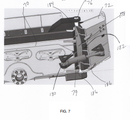
[0018] A FIG. 7 é uma vista traseira de uma lâmina tendo uma asa localizada em uma posição para a frente ou dobrada.[0018] FIG. 7 is a rear view of a blade having a wing located in a forward or folded position.
[0019] Para efeitos de promoção de um entendimento dos princípios da invenção inovadora, será feita agora referência às modalidades aqui descritas e ilustradas nos desenhos, e linguagem específica será usada para descrevê-las. No entanto, deve-se entender que não se pretende que haja qualquer limitação do escopo da nova invenção inovativa, tais alterações e modificações adicionais nos dispositivos e métodos ilustrados, e tais aplicações adicionais dos princípios da invenção inovadora como aqui ilustrado sendo contempladas como normalmente ocorreria a um versado na técnica aos quais a invenção inovadora diz respeito.[0019] For the purposes of promoting an understanding of the principles of the innovative invention, reference will now be made to the embodiments described herein and illustrated in the drawings, and specific language will be used to describe them. However, it should be understood that no limitation on the scope of the novel innovative invention is intended, such additional changes and modifications to the devices and methods illustrated, and such additional applications of the principles of the novel invention as illustrated herein being contemplated as would normally occur. to one skilled in the art to which the innovative invention pertains.
[0020] A FIG. 1 é uma vista lateral elevacional de um veículo de trabalho 10, como um trator de esteira, incluindo um implemento, tal como uma lâmina buldôzer 12, que é adequadamente acoplada ao buldôzer por um conjunto de articulação 14. Outros implementos, incluindo armações de lâmina, são contemplados. O veículo inclui uma armação ou chassi 16 que aloja um motor de combustão interna (não mostrado) localizado dentro de um alojamento 20. O veículo de trabalho 10 inclui uma cabina 22 onde um operador assenta para operar o veículo. O veículo é conduzido por um esteira circundante 24 que engata operacionalmente uma roda motriz principal traseira 26 e uma roda motriz auxiliar dianteira 28. A esteira circundante é tensionada pelo conjunto de tensão e retração 30. A esteira circundante é provida com olhais de guia de centralização para guiar a esteira ao longo das rodas motrizes e garras para engatar por atrito o chão.[0020] FIG. 1 is a side elevational view of a work vehicle 10, such as a bulldozer, including an implement, such as a
[0021] Embora as modalidades descritas sejam discutidas com referência a um trator de esteira, outros veículos de trabalho são contemplados, incluindo outros tipos de veículos de construção, veículos florestais, veículos de manutenção de gramado, bem como veículos na estrada, como aqueles usados para arar neve. Os atuadores ou cilindros de atuadores usados em um ou mais desses veículos de trabalho incluem atuadores de inclinação, ângulo, arfagem, elevação, braço, lança, caçamba, deslocamento lateral da lâmina, inclinação da lâmina e deslocamento lateral da sela. Nestes e em outros veículos, o operador tanto assenta quanto fica de pé na cabina e tem acesso aos controles do operador.[0021] While the described modalities are discussed with reference to a bulldozer, other work vehicles are contemplated, including other types of construction vehicles, forestry vehicles, lawn maintenance vehicles, as well as road vehicles such as those used to plow snow. The actuators or actuator cylinders used on one or more of these work vehicles include tilt, angle, pitch, lift, stick, boom, bucket, blade sideshift, blade tilt and saddle sideshift actuators. In these and other vehicles, the operator either sits or stands in the cab and has access to operator controls.
[0022] As rodas motrizes principais 26 são operacionalmente acopladas a um sistema de direção que, por sua vez, é acoplado a uma transmissão. A transmissão é operacionalmente acoplada à saída do motor de combustão interna. O sistema de direção pode ser de qualquer projeto convencional e pode ser um sistema de embreagem/freio, hidrostático ou direção diferencial. A transmissão pode ser uma transmissão de dupla embreagem tendo várias embreagens e freios que são atuados em resposta ao operador posicionar uma alavanca de controle de mudança (não mostrada) localizada na cabina 22.[0022] The
[0023] A lâmina do buldôzer 12 (o implemento) é levantada e abaixada pelo sistema de articulação 14 que inclui uma série de atuadores, tais como cilindros hidráulicos, para ajustar a posição da lâmina 12. O sistema de articulação 14 inclui um armação C 31, como visto na FIG. 2 como é entendido na técnica. A armação C 31 é levantada e abaixada em relação à armação 16 por um atuador de elevação 32 como mostrado na FIG. 1. O armação C na FIG. 1 é ilustrada genericamente. Um segundo atuador de elevação (não mostrado) está localizado em outro lado do alojamento 20. Em uma modalidade, cada um dos atuadores 32 inclui um atuador hidráulico incluindo um corpo, ou cilindro 34, rotacionalmente acoplado à armação 16 em um distanciador 36, e um braço 38 que se estende e retrai do cilindro 34. O braço 38 é rotacionalmente acoplado a uma chapa 40 que se estende a partir da estrutura C para levantar e abaixar a estrutura C e, portanto, a lâmina 12. Outras configurações de elevação e abaixamento da lâmina 12 são contempladas incluindo cilindros de elevação orientados verticalmente.[0023] The dozer blade 12 (the implement) is raised and lowered by the linkage system 14 which includes a series of actuators, such as hydraulic cylinders, to adjust the position of the
[0024] A lâmina 12 é inclinada em relação ao veículo de trabalho 10 pela atuação de um cilindro de inclinação 42, em que a lâmina 12 pode girar em torno de um eixo geométrico 44 de um mancal esférico 46. Para o cilindro de inclinação 42, uma extremidade da haste é conectada a pivô a uma manilha posicionada nos lados posterior e esquerdo da lâmina 12 acima do mancal esférico 46. Uma extremidade da cabeça do cilindro de inclinação 42 é conectada a pivô a uma porção saliente para cima 48 que se estende a partir da armação C 31. A extremidade oposta do cilindro de inclinação 42 é acoplada a um lado traseiro da lâmina 12. O posicionamento das conexões pivôs para a extremidade da cabeça e a extremidade da haste do cilindro de inclinação 42 resulta na inclinação da lâmina 12 para a esquerda (sentido antihorário) ou direita (sentido horário) quando vista da cabina 22. Extensão da haste do cilindro de inclinação 42 inclina a lâmina no sentido anti-horário. A retração do cilindro de inclinação 42 inclina a lâmina 12 para a direita ou no sentido horário quando vista da cabina do operador 22. Em modalidades alternativas, a lâmina 12 é inclinada por diferentes mecanismos (por exemplo, um motor elétrico ou hidráulico). O cilindro de inclinação 42, em uma ou mais modalidades, é configurado de forma diferente, tal como uma configuração em que o cilindro 42 é montado verticalmente e posicionado no lado esquerdo ou direito da lâmina 12, ou uma configuração com dois cilindros de inclinação.[0024] The
[0025] A lâmina 12 é angulada em relação ao veículo de trabalho 10 pela atuação dos cilindros de angulagem 50, um dos quais é ilustrado. Para cada um dos cilindros de angulagem 50, a extremidade da haste é conectada a pivô a uma lâmina 12, enquanto a extremidade da cabeça é conectada a pivô à armação 31. Um dos cilindros de angulagem 50 está posicionado no lado esquerdo do veículo de trabalho 10 e o outro cilindro de angulagem 50 está posicionado no lado direito do veículo de trabalho 10. Uma extensão do cilindro de angulagem esquerdo 50 e a retração do cilindro de angulagem direito 50 angulam a lâmina 12 para a direita de maneira que o lado direito da lâmina 12, como visto da cabina 22, é puxado para mais perto da cabina. A retração do cilindro de angulagem esquerdo 50 e a extensão do cilindro de angulagem direito 50 angulam a lâmina 12 para a esquerda, de maneira que o lado esquerdo da lâmina 12 seja puxado para mais perto da cabina 22. Em modalidades alternativas, a lâmina 12 é angulada por um mecanismo diferente ou os cilindros de angulagem 50 são configurados de forma diferente.[0025] The
[0026] A lâmina 12 é arfada em relação à cabina 22 com um cilindro de arfagem 53 conectado à porção saliente para cima 48, em uma extremidade, e conectado à lâmina 12 na outra extremidade. A extensão e retração do cilindro 53 movem uma borda superior 49 da lâmina 12 a favor e contra a cabina 12 para obter a arfagem desejada. A arfagem da lâmina 12 também é provida levantando e abaixando a armação C 31 com os cilindros de elevação 32 (vide FIG. 1) tendo extremidades acopladas aos locais pivôs 55. Em outra modalidade, o cilindro de arfagem 53 não está incluído e a retração e a extensão dos cilindros 50 arfam a lâmina 12 em torno do mancal esférico 46.[0026]
[0027] Um ou mais dispositivos de controle de implemento 52, localizados em uma interface de usuário de uma estação de trabalho 54, são acessíveis ao operador localizado na cabina 22. A estação de trabalho de usuário inclui um console dianteiro 56, suportando uma barra de apoio 57 localizada na parte dianteira da cabina 22 e uma estação de trabalho 58 localizada em ou perto dos braços de uma cadeira de operador 60. Os dispositivos de controle 52 estão operacionalmente conectados a um controlador 62. O controlador 62 recebe sinais dos dispositivos de controle 52 para ajustar a posição da lâmina 12. Em outras modalidades, os dispositivos de controle de implemento estão localizados no console dianteiro 56 ou no console dianteiro 56 e na estação de trabalho 58.[0027] One or more implement control devices 52, located on a
[0028] Os dispositivos de controle 52 estão localizados em uma interface de usuário que inclui uma pluralidade de botões, interruptores, controles tipo manche e alternadores selecionáveis pelo operador configurados para permitir que o operador controle as operações e funções do veículo 10. A interface do usuário, em uma modalidade, inclui um dispositivo de interface do usuário incluindo uma tela de exibição com uma pluralidade de botões selecionáveis pelo usuário para selecionar a partir de uma pluralidade de comandos ou menus, cada um dos quais é selecionável por meio de uma tela sensível ao toque tendo uma exibição. Em outra modalidade, a interface de usuário inclui uma pluralidade de botões de aperto mecânicos, bem como uma tela sensível ao toque. Em ainda outra modalidade, a interface do usuário inclui uma tela de exibição e apenas botões de aperto mecânicos. Em uma ou mais modalidades, o ajuste da lâmina em relação à armação é feito usando uma ou mais alavancas ou controles tipo manche.[0028] Control devices 52 are located in a user interface that includes a plurality of buttons, switches, joystick controls and operator selectable switches configured to allow the operator to control the operations and functions of the vehicle 10. The user, in one embodiment, includes a user interface device including a display screen with a plurality of user-selectable buttons for selecting from a plurality of commands or menus, each of which is selectable via a touchscreen to the touch having a display. In another embodiment, the user interface includes a plurality of mechanical grip buttons as well as a touch screen. In yet another embodiment, the user interface includes a display screen and mechanical grip buttons only. In one or more embodiments, the adjustment of the blade in relation to the frame is done using one or more levers or joystick controls.
[0029] O ajuste dos atuadores 32, 42 e 50 é feito pelo operador usando os dispositivos de controle 52 que estão operacionalmente acoplados ao controlador 62, como visto na FIG. 5, que em uma modalidade, está localizado dentro da armação 16. Outros locais do controlador 62 são contemplados, incluindo a cabina 22. Os dispositivos de controle 52 estão operacionalmente conectados ao controlador 62 que é operacional para ajustar os cilindros de elevação 32, cilindros de inclinação 42, os cilindros de angulagem 50 e o cilindro de arfagem 53. O ajuste de um ou mais dos dispositivos de controle gera uma posição comandada recebida pelo controlador 62 que identifica ao controlador 62 uma direção e posição final da lâmina para realizar uma operação de nivelamento desejada.[0029] The adjustment of
[0030] Na FIG. 1, uma antena 64 está localizada na parte superior da cabina 22 e é configurada para receber e transmitir sinais de diferentes tipos de sistemas de controle de máquina e/ou sistemas de informação de máquina, incluindo sistemas de posicionamento global (GPS). Embora a antena 64 seja ilustrada em uma porção superior da cabina 22, outras localizações da antena 64 são contempladas como é conhecido por aqueles versados na técnica.[0030] In FIG. 1, an
[0031] A lâmina 12, conforme ilustrado nas FIGS. 3 e 4, inclui uma porção central 70, uma primeira asa 72 conectada rotacionalmente a um lado da porção central 70 e uma segunda asa 74 rotacionalmente acoplada a outro lado da porção central 70. Cada uma dentre as primeira e segunda asas 72 e 74 é respectivamente rotacionalmente acoplada à porção central 70 em uma primeira dobradiça 76 e uma segunda dobradiça 78. Cada asa 72 e 74 é movimentada de forma ajustável por um atuador de asa 79 como ilustrado na FIG. 2. Cada uma das FIGS. 3 e 4 ilustra as asas 72 e 74 sendo dobradas para dentro ou em direção a um trajeto percorrido pelo veículo 10. Se cada asa 72 e 74 não for dobrada, mas ficar substancialmente plana com a porção central 70 como ilustrado na FIG. 1, a borda inferior 51 de toda a lâmina 12 que se estende de uma asa à outra asa é substancialmente plana em relação a uma superfície do chão 82 e fica em contato com a superfície do chão 82 quando abaixada o suficiente. Se, entretanto, as asas 72 e 74 forem dobradas e a arfagem da lâmina 12 permanecer a mesma ilustrada na FIG. 1, toda a borda 51 de asa a asa permanece em contato com o chão quando abaixada.[0031]
[0032] Como ilustrado na FIG. 3, caso a lâmina 12 seja arfada para a frente, apenas um ponto da extremidade de avanço 84 de cada asa entra em contato com o chão 82. Nesta condição, uma lacuna 86 aparece entre a porção central 70 da lâmina e o chão 82, e o material a ser movimentado pela lâmina 12 move-se através da lacuna 86, o que reduz a eficácia de uma operação da lâmina. Os materiais a serem movimentados incluem sujeira, solo, agregados, neve e gelo para o local desejado. Outros materiais são contemplados.[0032] As illustrated in FIG. 3, if the
[0033] Também, como ilustrado na FIG. 4, se a lâmina 12 é inclinada para trás sem levantar a lâmina 12, apenas a borda inferior 51 entra em contato com o chão 82 e os pontos da extremidade de avanço 84 são elevados em relação ao chão 82. Nesta condição, uma lacuna 88 aparece entre os pontos de extremidade 84 da lâmina e o chão 82. Parte do material a ser movimentado pela lâmina 12, consequentemente, move-se através das lacunas 88, o que reduz a eficácia de uma operação da lâmina.[0033] Also, as illustrated in FIG. 4, if the
[0034] Como ilustrado por ambas as FIGS. 3 e 4, o ponto de contato da lâmina com o chão em uma lâmina reta ou uma lâmina com asas orientadas da mesma maneira que uma lâmina reta é um ponto, quando vista por um lado, ou uma borda reta, quando vista pela frente. Mesmo com a lâmina totalmente para baixo na superfície 82 e com as asas 72 e 74 não sendo inclinadas em relação à lâmina central 70, a borda 51 de asa a asa faz contato com o chão ao mesmo tempo. Com uma lâmina dobrável, entretanto, como ilustrado nas FIGS. 3 e 4, qualquer quantidade de dobramento das seções de asa 72 ou 74 faz com que a borda 51 entre em contato com o chão 82 em apenas uma posição de arfagem da lâmina. Quando a lâmina é arfada para a frente ou para trás, a partir de um nível nominal da FIG. 2, as arestas de corte das asas 72 ou 72 não estão fazendo contato com o chão no mesmo nível que a aresta de corte da porção central das asas. Por exemplo, como visto na FIG. 3, a borda de avanço da aresta de corte da asa está cortando mais profundamente no chão do que a aresta de corte da porção central.[0034] As illustrated by both FIGS. 3 and 4, the point of blade contact with the ground on a straight blade or a blade with wings oriented in the same way as a straight blade is a point, when viewed from the side, or a straight edge, when viewed from the front. Even with the blade all the way down on the surface 82 and with the
[0035] Para superar as lacunas que estão localizadas na lâmina central ou nas asas, um operador tem que ajustar a arfagem da lâmina de maneira que as bordas das asas 72 e 74 correspondam ao nível da borda da porção central 70. Em virtude de ser difícil para o operador ver as arestas de corte da lâmina 12, o alinhamento da lâmina 12 em relação ao chão 82 pode ser muito difícil. Tal operação requer extrema concentração, mesmo para um operador experiente. De fato, em algumas condições em que as condições do chão e climáticas não são ideais, colocar corretamente a lâmina 12 é quase impossível. Similarmente, por causa da geometria da junta de esfera 46 entre a lâmina 12 e o armação C 31, a inclinação da lâmina 12 pode afetar a arfagem da lâmina.[0035] To overcome gaps that are located in the central blade or wings, an operator has to adjust the pitch of the blade so that the edges of the
[0036] Para superar as deficiências apresentadas pelo nivelamento de uma superfície com uma lâmina com asas, a presente descrição inclui um sistema de controle 100 ilustrado na FIG. 5, que mantém as posições da lâmina 12 em relação ao chão 82 quando as asas 72 e 74 estão inclinadas em relação à porção central 70. Ajustando automaticamente a posição da lâmina em resposta a uma entrada de controle do operador, a borda da lâmina de uma asa até a porção central da lâmina, e até a outra asa, é mantida substancialmente ao longo de um plano identificado pelo controle do operador para realizar uma operação de nivelamento.[0036] To overcome the deficiencies presented by leveling a surface with a winged blade, the present description includes a control system 100 illustrated in FIG. 5, which maintains the positions of the
[0037] Como visto na FIG. 5, o sistema de controle 100 inclui o controlador 62 que inclui um processador 104 e uma memória 106. Em outras modalidades, o controlador 62 é um controlador distribuído tendo controladores individuais separados distribuídos em diferentes locais no veículo 10. Além do mais, o controlador é geralmente conectado por fio por fiação ou cabeamento elétrico a componentes relacionados. Em outras modalidades, entretanto, o controlador 62 inclui um transmissor e/ou receptor sem fio para comunicar com um componente ou dispositivo controlado ou de sensoreamento que tanto provê informações ao controlador quanto transmite informações do controlador para dispositivos controlados.[0037] As seen in FIG. 5, control system 100 includes
[0038] O controlador 62, em diferentes modalidades, inclui um computador, sistema de computador ou outros dispositivos programáveis. Em outras modalidades, o controlador 62 inclui um ou mais processadores 104 (por exemplo, microprocessadores) e a memória associada 106, que pode ser interna ao processador ou externa ao processador. A memória 106 inclui, em uma ou mais modalidades, dispositivos de memória de acesso aleatório (RAM) que compreendem o armazenamento de memória do controlador 62, bem como quaisquer outros tipos de memória, por exemplo, memórias cache, memórias não voláteis ou reserva, memórias programáveis, ou memórias flash e memórias apenas de leitura. Adicionalmente, a memória pode incluir um armazenamento de memória fisicamente localizado em outro lugar nos dispositivos de processamento e pode incluir qualquer memória cache em um dispositivo de processamento, bem como qualquer capacidade de armazenamento usada como uma memória virtual, por exemplo, armazenada em um dispositivo de armazenamento em massa ou outro computador acoplado ao controlador 62. O dispositivo de armazenamento em massa pode incluir um cache ou outro espaço de dados que pode incluir bases de dados. O armazenamento de memória, em outras modalidades, está localizado na "nuvem", onde a memória está localizada em um local distante que provê a informação armazenada de uma forma sem fio ao controlador 62.[0038]
[0039] O controlador 62 executa ou de outra forma conta com aplicações de software de computador, componentes, programas, objetos, módulos ou estruturas de dados, etc. As rotinas de software residentes na memória incluída 106 do controlador 62, ou outra memória, são executadas em resposta aos sinais recebidos. Os aplicativos de software de computador, em outras modalidades, estão localizados nas nuvens. O software executado inclui uma ou mais aplicações, componentes, programas, objetos, módulos ou sequências de instruções específicos tipicamente referidos como "código de programa". O código de programa inclui uma ou mais instruções localizadas na memória e outros dispositivos de armazenamento que executam as instruções residentes na memória, que são responsivas a outras instruções geradas pelo sistema, ou que são providas em uma interface de usuário operada pelo usuário. O processador 104 é configurado para executar as instruções de programa armazenado, bem como acessar os dados armazenados em uma ou mais tabelas de dados. Uma unidade telemática 108, ou um transmissor e/ou receptor, é operacionalmente conectado à antena 64 para receber e transmitir informações sem fio por meio de comunicação celular ou outros tipos de comunicação, incluindo satélite.[0039]
[0040] O processador 104 e a memória 106 são configurados para monitorar a posição das asas 72 e 74, e, quando qualquer uma das asas 72 ou 74 é rotacionada para frente, o controlador 62 comanda a arfagem da lâmina 12 para manter a borda 51 da lâmina de asa a asa ao longo de um plano. A arfagem comandada é baseada na posição da lâmina atualmente sensoreada para manter a borda de avanço da aresta de corte das asas no mesmo nível da porção central da aresta de corte das lâminas, por meio disso mantendo o nivelamento. Quando as asas 72 e 74 são articuladas e que não em paralelo em relação à porção central 70, o controlador 62 ajusta a arfagem da lâmina 12 em relação ao chão com base em entradas dos controles do operador e das entradas de sensor para ajustar a arfagem da lâmina, que ajusta a aresta de corte da lâmina de um asa à outra asa. Em diferentes modalidades, cada asa 72 ou 74 é individualmente controlável de maneira que o ângulo de uma asa seja diferente do ângulo da outra asa.[0040] Processor 104 and
[0041] O veículo 10 inclui um monitor de máquina 110 que, em diferentes modalidades, inclui uma ou mais câmeras localizadas no veículo, e uma tela de exibição visual, localizada na cabina 22, para exibir o veículo, incluindo a posição do veículo em relação ao chão, como direção, inclinação e posição em uma área de trabalho que está sendo nivelada. A inclinação do chassi é provida por um sensor de inclinação do chassi 112, como uma unidade de medição inercial (IMU), que transmite sinais de inclinação ao controlador 62, que, em uma ou mais modalidades, são usados pelo processador 104 para ajustar a posição da lâmina. Informação de lâmina adicional é provida por um sensor de posição da lâmina 114, que, em diferentes modalidades, inclui uma IMU ou um sensor de cilindro. Em uma modalidade, um sensor de cilindro inclui um sensor interno que determina a quantidade de extensão de um braço de cilindro a partir de um corpo de cilindro. O sinal resultante é recebido no processador 104 e usado para determinar a posição da lâmina. Em uma modalidade, uma ou mais tabelas de dados 116 incluem informações cinemáticas que, em combinação com o sinal de posição da lâmina recebido do sensor 114, determina a posição da lâmina.[0041] Vehicle 10 includes a
[0042] Cada uma das asas 72 e 74, que é movimentada por um dos cilindros de asa 79, inclui um sensor de posição de ângulo de asa de lâmina 118. Em uma modalidade, o sensor 118 está localizado no local pivô em torno do qual a asa pivota, tal como um sensor de ângulo rotativo. Em outra modalidade, um sensor de cilindro determina a extensão do braço do cilindro da asa do cilindro da asa usado para determinar o ângulo da asa. Outros sensores são contemplados.[0042] Each of the
[0043] Cada um dos cilindros de elevação 32, os cilindros de inclinação 42 e o cilindro de arfagem 53, são acoplados às válvulas de controle 122 para movimentar o cilindro apropriado da maneira direcionada pelos controles do operador 52. Válvulas de desvio de ângulo/asa 124 são operacionalmente conectadas aos cilindros de asa 79 como é entendido por um versado na técnica.[0043] Each of the
[0044] O processador 104 recebe sinais de status e posição de cada um dos sensores, IMUs ou sensores de posição do cilindro e determina a posição da lâmina 12 com base nesses sinais de entrada. A memória 106 inclui um modelo cinemático da lâmina 12 e a geometria da armação C 31. O processador 104 determina, com base nas instruções de programa, quando posicionar a lâmina, quanto posicionar a lâmina e a localização final da lâmina 12 com base nos controles de usuário 52 que provêm a direção e magnitude dos comandos de válvula de elevação, inclinação e/ou arfagem da lâmina. Mediante determinação desses valores, a arfagem da lâmina é ajustada automaticamente de maneira que cada uma das arestas de corte das asas 72, 74 e a lâmina central 70 estejam localizadas substancialmente no nível com a superfície que está sendo nivelada. Em outra modalidade, as asas 72 e 74 são ajustadas, bem como a arfagem da lâmina, comandando as posições das asas ao mesmo tempo em que a lâmina levanta/inclina para melhorar o desempenho e fazer um corte suave sem que as bordas da asa cortem o nivelamento ou que sejam levantadas acima do nível.[0044] Processor 104 receives status and position signals from each of the sensors, IMUs or cylinder position sensors and determines the position of
[0045] A FIG. 6 ilustra um diagrama de blocos 150 de um processo para posicionar automaticamente a lâmina 12 com base na posição das asas 72 e 74 em resposta a um comando de lâmina do operador. Inicialmente, no bloco 152, o controlador 62 determina a posição das asas 72 e 74. Em uma modalidade, a posição de cada asa 72 e 74 com a porção central 70 é a mesma. Uma vez que a projeção da asa da lâmina é determinada no bloco 152, o valor determinado é comparado à posição não inclinada das asas para determinar se as asas estão inclinadas ("dobradas" na direção de deslocamento) no bloco 154. Se não, o processo retorna para o bloco 152 para determinar quando as asas são dobradas. Se as asas forem dobradas no bloco 154, uma inclinação longitudinal da lâmina é identificada pelo sensor de posição da lâmina 114 no bloco 156. A inclinação longitudinal da lâmina identifica a inclinação da aresta de corte 51 da porção central da lâmina 70. Este valor da inclinação longitudinal da lâmina é armazenado na memória 106 ou em outros locais de armazenamento. No bloco 158, uma inclinação na direção longitudinal do chassi é determinada e armazenada na memória 106. A inclinação na direção longitudinal do chassi identifica uma inclinação do veículo na direção do percurso do veículo em relação à gravidade. Uma vez que os valores da inclinação na direção longitudinal da lâmina e a inclinação na direção longitudinal do chassi são determinadas, o controlador 62 determina no bloco 160 se a arfagem da lâmina 12 precisa ser ajustada para manter a borda da lâmina, incluindo as bordas da asa, em um local que é substancialmente paralelo à superfície e, em particular, a nivelamento pretendido que está sendo preparado pelo operador usando os dispositivos de controle 52. Se a arfagem da lâmina tiver que ser ajustada como determinado no bloco 160, o controlador 62 determina a arfagem da lâmina necessária para atingir a posição comandada da lâmina 12 no bloco 162. Em uma ou mais modalidades, o sinal da lâmina comandado é modificado pelo controlador 62 para atingir uma arfagem da lâmina que alinha as bordas das asas e a porção central da lâmina com o nivelamento pretendido. Uma vez que a posição da lâmina necessária é determinada, a arfagem da lâmina é ajustada, quando necessário, no bloco 164.[0045] FIG. 6 illustrates a block diagram 150 of a process for automatically positioning
[0046] O processo de ajuste da arfagem da lâmina, com base na posição da asa, é feito à medida que o operador move a lâmina para cima ou para baixo, ajusta a inclinação da lâmina ou o ângulo da lâmina. O sistema de controle do veículo ajusta automaticamente a arfagem da lâmina em resposta aos comandos do operador transmitidos pelos controles do operador, de maneira que a borda de avanço das asas esteja no mesmo nível da aresta de corte da porção central, mantendo assim o nivelamento. A forma dos locais pivôs das asas 76 e 78 em relação ao conjunto de lâmina principal 70 juntamente com as curvas salientes sobrepostas 170 e 172 do conjunto de lâmina 12 minimiza a lacuna entre o chão e a lâmina de modo a impedir que material passe através ou por baixo das asas ou da porção central da lâmina. As curvas salientes sobrepostas 170 e 172 são, cada uma, bordas de uma chapa metálica 178 formando a superfície frontal da lâmina 12.[0046] The blade pitch adjustment process, based on the wing position, is done as the operator moves the blade up or down, adjusts the blade pitch or blade angle. The vehicle's control system automatically adjusts blade pitch in response to operator commands transmitted from the operator controls so that the leading edge of the wings is level with the cutting edge of the center portion, thus maintaining levelness. The shape of the
[0047] FIGO. 7 é uma vista traseira do conjunto de lâmina 12 tendo a asa 72 localizada em uma posição dianteira ou dobrada. O atuador 79 é estendido para inclinar a asa 72 em relação à porção central 70 da lâmina 12. Nesta posição, uma armação 180 da porção central 70 é espaçada de uma armação 182 da asa 72, de maneira que uma lacuna 184 esteja localizada entre cada armação 180 e 182. A lacuna 184, entretanto, é substancialmente fechada na frente da lâmina 12 pela extremidade da chapa metálica como visto na FIG. 7. Vide também as vistas frontais das FIGS 3 e 4. Quando as asas 70 e 72 são planas com a porção central 70, a chapa metálica 178 se estende sobre uma chapa metálica que define a superfície frontal das asas. Quando as asas 70 e 72 estão inclinadas, entretanto, a chapa metálica 178 cobre a lacuna 184 e impede substancialmente que o material movimente através da lacuna 184. Como as superfícies frontais da porção intermediária 70 e as asas 72 e 74 são côncavas, as extremidades sobrepostas do material da porção central não são substancialmente deformadas pela inclinação das asas. A lâmina 12 inclui estruturas de bloqueio 186 para impedir movimento adicional das asas em relação à porção central 70 quando as asas não estão inclinadas.[0047] FIG. 7 is a rear view of
[0048] Embora modalidades exemplificativas que incorporam os princípios da presente descrição tenham sido descritas no presente documento, a presente descrição não está limitada às modalidades descritas. Em vez disso, este pedido visa cobrir quaisquer variações, usos ou adaptações da descrição usando seus princípios gerais. Além do mais, embora as expressões maior que e menor que tenham sido usadas para fazer comparação, entende-se que qualquer determinação de menor ou maior que pode incluir a determinação de ser igual a um valor. Adicionalmente, este pedido se destina a cobrir tais desvios da presente descrição como vêm dentro da prática conhecida ou habitual na técnica à qual esta descrição diz respeito e que caem dentro dos limites das reivindicações anexas.[0048] While exemplary embodiments embodying the principles of the present description have been described herein, the present description is not limited to the described embodiments. Rather, this order is intended to cover any variations, uses, or adaptations of the description using its general principles. Furthermore, although the terms greater than and less than have been used to make comparison, it is understood that any determination of less than or greater than may include the determination of being equal to a value. Additionally, this application is intended to cover such deviations from the present description as come within the known or customary practice in the art to which this description pertains and which fall within the limits of the appended claims.
Claims (20)
Applications Claiming Priority (2)
| Application Number | Priority Date | Filing Date | Title |
|---|---|---|---|
| US17/028,107 | 2020-09-22 | ||
| US17/028,107 US11926988B2 (en) | 2020-09-22 | 2020-09-22 | Work machine with automatic pitch control of implement |
Publications (1)
| Publication Number | Publication Date |
|---|---|
| BR102021013040A2 true BR102021013040A2 (en) | 2022-03-29 |
Family
ID=80474263
Family Applications (1)
| Application Number | Title | Priority Date | Filing Date |
|---|---|---|---|
| BR102021013040-7A BR102021013040A2 (en) | 2020-09-22 | 2021-06-30 | Methods for positioning a blade and for moving materials with a blade and work vehicle |
Country Status (4)
| Country | Link |
|---|---|
| US (1) | US11926988B2 (en) |
| AU (2) | AU2021218108A1 (en) |
| BR (1) | BR102021013040A2 (en) |
| DE (1) | DE102021208926A1 (en) |
Families Citing this family (8)
| Publication number | Priority date | Publication date | Assignee | Title |
|---|---|---|---|---|
| US12098517B2 (en) | 2020-09-22 | 2024-09-24 | Deere & Company | Work machine with automatic pitch control of implement |
| US11926988B2 (en) | 2020-09-22 | 2024-03-12 | Deere & Company | Work machine with automatic pitch control of implement |
| US12173470B2 (en) * | 2020-10-27 | 2024-12-24 | Phil PAULL | Apparatus and method for enhanced skid loader grading control |
| US11885086B2 (en) * | 2020-12-03 | 2024-01-30 | Caterpillar Inc. | Adjustable blade assembly |
| BR102022008531A2 (en) | 2021-09-24 | 2023-04-11 | Deere & Company | METHOD FOR POSITIONING A BLADE TO A WORK VEHICLE, AND, WORK VEHICLE |
| CN115196372B (en) * | 2022-06-30 | 2024-04-02 | 苏州艾氪英诺机器人科技有限公司 | Material unloading control method and device and electronic equipment |
| US20240247464A1 (en) * | 2023-01-20 | 2024-07-25 | Martin Nicolas Benoît BILODEAU | Differential dozer blade lift and angle mechanism |
| US20260035878A1 (en) * | 2024-08-02 | 2026-02-05 | Kubota Corporation | Working vehicle and attachment usage system |
Family Cites Families (22)
| Publication number | Priority date | Publication date | Assignee | Title |
|---|---|---|---|---|
| US3157099A (en) | 1960-09-06 | 1964-11-17 | Ulrich Mfg Co | Earth materials handling apparatus |
| US4099578A (en) | 1977-02-10 | 1978-07-11 | Stevens John L | Hinged bulldozer blade |
| US4135583A (en) | 1977-04-04 | 1979-01-23 | Becker Clarence A | Bulldozer blade |
| US4356645A (en) * | 1978-06-19 | 1982-11-02 | De Lorean Manufacturing Company | Variable wing plow blade and mounting structure therefor |
| JPS5980829A (en) * | 1982-10-29 | 1984-05-10 | Kubota Ltd | Tractor with soil scraper |
| US5987371A (en) * | 1996-12-04 | 1999-11-16 | Caterpillar Inc. | Apparatus and method for determining the position of a point on a work implement attached to and movable relative to a mobile machine |
| US6425196B1 (en) | 2000-08-08 | 2002-07-30 | Pro-Tech Welding And Fabrication, Inc. | Folding pusher |
| US6442877B1 (en) | 2000-10-12 | 2002-09-03 | Blizzard Corporation | Plow with rear mounted, adjustable wing |
| US8919455B2 (en) | 2008-03-07 | 2014-12-30 | Deere & Company | Dozer blade pitch control system |
| US20110213529A1 (en) * | 2010-02-26 | 2011-09-01 | Caterpillar Inc. | System and method for determing a position on an implement relative to a reference position on a machine |
| US20120059554A1 (en) * | 2010-09-02 | 2012-03-08 | Topcon Positioning Systems, Inc. | Automatic Blade Control System during a Period of a Global Navigation Satellite System ... |
| US9151006B2 (en) | 2012-02-09 | 2015-10-06 | Pro-Tech Manufacturing And Distribution, Inc. | Material pusher with control system |
| CA3114364C (en) * | 2013-09-26 | 2023-04-25 | 9277-9347 Quebec Inc. | Equipment for forming surfaces, method of manufacture and use of the equipment for forming surfaces and mobile unit including the equipment for forming surfaces |
| DE102014200899A1 (en) | 2013-12-20 | 2015-06-25 | Kässbohrer Geländefahrzeug AG | Snow groomer and plow blade for such a snowcat |
| US9593461B2 (en) * | 2014-05-19 | 2017-03-14 | Caterpillar Inc. | Work tool pitch control system for a machine |
| US9328479B1 (en) * | 2015-02-05 | 2016-05-03 | Deere & Company | Grade control system and method for a work vehicle |
| US9624643B2 (en) | 2015-02-05 | 2017-04-18 | Deere & Company | Blade tilt system and method for a work vehicle |
| US10066370B2 (en) | 2015-10-19 | 2018-09-04 | Caterpillar Inc. | Sensor fusion for implement position estimation and control |
| US10435864B2 (en) | 2016-02-01 | 2019-10-08 | Stonebrooke Equipment Inc. | Plow assembly with valve system for wings |
| US10865542B2 (en) | 2018-01-25 | 2020-12-15 | Caterpillar Inc. | Grading control system using machine linkages |
| US10132050B1 (en) | 2018-04-27 | 2018-11-20 | Forest P. Mandan | Variable geometry bucket |
| US11926988B2 (en) | 2020-09-22 | 2024-03-12 | Deere & Company | Work machine with automatic pitch control of implement |
-
2020
- 2020-09-22 US US17/028,107 patent/US11926988B2/en active Active
-
2021
- 2021-06-30 BR BR102021013040-7A patent/BR102021013040A2/en unknown
- 2021-08-13 DE DE102021208926.7A patent/DE102021208926A1/en active Pending
- 2021-08-19 AU AU2021218108A patent/AU2021218108A1/en not_active Abandoned
-
2024
- 2024-08-09 AU AU2024205645A patent/AU2024205645A1/en active Pending
Also Published As
| Publication number | Publication date |
|---|---|
| US20220090349A1 (en) | 2022-03-24 |
| AU2021218108A1 (en) | 2022-04-07 |
| AU2024205645A1 (en) | 2024-08-29 |
| DE102021208926A1 (en) | 2022-03-24 |
| US11926988B2 (en) | 2024-03-12 |
Similar Documents
| Publication | Publication Date | Title |
|---|---|---|
| BR102021013040A2 (en) | Methods for positioning a blade and for moving materials with a blade and work vehicle | |
| DE112015000101B4 (en) | Work machine control device, work machine and work machine control method | |
| US7121355B2 (en) | Bulldozer autograding system | |
| US11142890B2 (en) | System and method of soil management for an implement | |
| JP7402026B2 (en) | Work machine control system, work machine, work machine control method | |
| DE112016000090B4 (en) | CONSTRUCTION MACHINE CONTROL SYSTEM, CONSTRUCTION MACHINE AND CONSTRUCTION MACHINE CONTROL METHOD | |
| US11180902B2 (en) | Forward looking sensor for predictive grade control | |
| US20130085645A1 (en) | Blade control system and construction machine | |
| US10030357B1 (en) | Vehicle speed control based on grade error | |
| JP7640655B2 (en) | Work machine, method and system | |
| BR102021008044A2 (en) | GROUND HITCH TOOL CONTROL SYSTEM, WORK VEHICLE, AND METHOD TO PROVIDE COORDINATED BLADE CONTROL | |
| BR102020014617A2 (en) | articulated vehicle, automatic steering system for an articulated working vehicle, and method for automatically steering an articulated working vehicle | |
| US20220090353A1 (en) | Work machine with automatic pitch control of implement | |
| US12091832B2 (en) | System and method of tilting a track loader bucket to achieve desired cross slope | |
| US11505920B2 (en) | Grade control having real time cylinder stop lengths | |
| BR102022008531A2 (en) | METHOD FOR POSITIONING A BLADE TO A WORK VEHICLE, AND, WORK VEHICLE | |
| BR102021013055A2 (en) | BLADE FOR A WORK MACHINE | |
| AU2021277679B2 (en) | Work machine with automatic pitch control of implement | |
| AU2022203813A1 (en) | Work machine with automatic pitch control of implement | |
| BR102024011814A2 (en) | MOTOR GRADER, AND, METHOD FOR DETERMINING A BLADE'S TRAJECTORY PATH | |
| JP2535779Y2 (en) | Lifting device for traveling wheels in a walking type paddy working machine | |
| JP2002339390A (en) | Working vehicle | |
| JP2002339388A (en) | Working vehicle | |
| JPH1189318A (en) | Tractor | |
| JPS6131968B2 (en) |
Legal Events
| Date | Code | Title | Description |
|---|---|---|---|
| B03A | Publication of a patent application or of a certificate of addition of invention [chapter 3.1 patent gazette] | ||
| B06W | Patent application suspended after preliminary examination (for patents with searches from other patent authorities) chapter 6.23 patent gazette] |