BR102020025177A2 - agricultural row unit particle distribution system - Google Patents
agricultural row unit particle distribution system Download PDFInfo
- Publication number
- BR102020025177A2 BR102020025177A2 BR102020025177-5A BR102020025177A BR102020025177A2 BR 102020025177 A2 BR102020025177 A2 BR 102020025177A2 BR 102020025177 A BR102020025177 A BR 102020025177A BR 102020025177 A2 BR102020025177 A2 BR 102020025177A2
- Authority
- BR
- Brazil
- Prior art keywords
- particle
- disk
- particles
- controller
- distribution system
- Prior art date
Links
- 239000002245 particle Substances 0.000 title claims abstract description 1544
- 238000009826 distribution Methods 0.000 title claims abstract description 186
- 238000012546 transfer Methods 0.000 claims abstract description 258
- 230000004044 response Effects 0.000 claims description 36
- 238000003860 storage Methods 0.000 claims description 13
- 230000003247 decreasing effect Effects 0.000 claims description 8
- 238000004891 communication Methods 0.000 claims description 3
- 239000012530 fluid Substances 0.000 claims description 3
- 238000000034 method Methods 0.000 description 47
- 230000008569 process Effects 0.000 description 45
- 239000002689 soil Substances 0.000 description 22
- 230000007423 decrease Effects 0.000 description 15
- 230000001133 acceleration Effects 0.000 description 14
- 230000005484 gravity Effects 0.000 description 12
- 238000005259 measurement Methods 0.000 description 9
- 230000006835 compression Effects 0.000 description 7
- 238000007906 compression Methods 0.000 description 7
- 238000000151 deposition Methods 0.000 description 7
- 230000008021 deposition Effects 0.000 description 6
- 238000011161 development Methods 0.000 description 4
- 230000018109 developmental process Effects 0.000 description 4
- 239000003337 fertilizer Substances 0.000 description 4
- 238000003032 molecular docking Methods 0.000 description 4
- 108010016634 Seed Storage Proteins Proteins 0.000 description 3
- 230000008901 benefit Effects 0.000 description 3
- 230000003993 interaction Effects 0.000 description 3
- 239000000463 material Substances 0.000 description 3
- 238000006073 displacement reaction Methods 0.000 description 2
- 230000006870 function Effects 0.000 description 2
- 238000004519 manufacturing process Methods 0.000 description 2
- 238000012986 modification Methods 0.000 description 2
- 230000004048 modification Effects 0.000 description 2
- 230000035515 penetration Effects 0.000 description 2
- 230000008121 plant development Effects 0.000 description 2
- 230000000750 progressive effect Effects 0.000 description 2
- 230000000903 blocking effect Effects 0.000 description 1
- 230000008878 coupling Effects 0.000 description 1
- 238000010168 coupling process Methods 0.000 description 1
- 238000005859 coupling reaction Methods 0.000 description 1
- 238000013461 design Methods 0.000 description 1
- 230000007613 environmental effect Effects 0.000 description 1
- 239000004744 fabric Substances 0.000 description 1
- 238000010899 nucleation Methods 0.000 description 1
- 230000003287 optical effect Effects 0.000 description 1
- 239000011236 particulate material Substances 0.000 description 1
- -1 seeds Substances 0.000 description 1
Images


Classifications
-
- A—HUMAN NECESSITIES
- A01—AGRICULTURE; FORESTRY; ANIMAL HUSBANDRY; HUNTING; TRAPPING; FISHING
- A01C—PLANTING; SOWING; FERTILISING
- A01C7/00—Sowing
- A01C7/20—Parts of seeders for conducting and depositing seed
-
- A—HUMAN NECESSITIES
- A01—AGRICULTURE; FORESTRY; ANIMAL HUSBANDRY; HUNTING; TRAPPING; FISHING
- A01C—PLANTING; SOWING; FERTILISING
- A01C7/00—Sowing
- A01C7/04—Single-grain seeders with or without suction devices
- A01C7/042—Single-grain seeders with or without suction devices using pneumatic means
- A01C7/044—Pneumatic seed wheels
- A01C7/0445—Seed ejectors
-
- A—HUMAN NECESSITIES
- A01—AGRICULTURE; FORESTRY; ANIMAL HUSBANDRY; HUNTING; TRAPPING; FISHING
- A01C—PLANTING; SOWING; FERTILISING
- A01C7/00—Sowing
- A01C7/04—Single-grain seeders with or without suction devices
- A01C7/042—Single-grain seeders with or without suction devices using pneumatic means
- A01C7/044—Pneumatic seed wheels
- A01C7/046—Pneumatic seed wheels with perforated seeding discs
-
- A—HUMAN NECESSITIES
- A01—AGRICULTURE; FORESTRY; ANIMAL HUSBANDRY; HUNTING; TRAPPING; FISHING
- A01C—PLANTING; SOWING; FERTILISING
- A01C7/00—Sowing
- A01C7/08—Broadcast seeders; Seeders depositing seeds in rows
- A01C7/10—Devices for adjusting the seed-box ; Regulation of machines for depositing quantities at intervals
- A01C7/102—Regulating or controlling the seed rate
-
- A—HUMAN NECESSITIES
- A01—AGRICULTURE; FORESTRY; ANIMAL HUSBANDRY; HUNTING; TRAPPING; FISHING
- A01C—PLANTING; SOWING; FERTILISING
- A01C7/00—Sowing
- A01C7/08—Broadcast seeders; Seeders depositing seeds in rows
- A01C7/081—Seeders depositing seeds in rows using pneumatic means
- A01C7/082—Ducts, distribution pipes or details thereof for pneumatic seeders
Landscapes
- Life Sciences & Earth Sciences (AREA)
- Soil Sciences (AREA)
- Environmental Sciences (AREA)
- Fertilizing (AREA)
- Pretreatment Of Seeds And Plants (AREA)
Abstract
Trata-se de um sistema de distribuição de partícula (40, 240) de uma unidade de fileira agrícola (12) que inclui um primeiro disco de partícula (82) configurado para medir partículas (80) e um segundo disco de partícula (84) configurado para receber as partículas (80) a partir do primeiro disco de partícula (82) e para transferir as partículas (80) em direção a uma vala (31) no solo. O sistema de distribuição de partícula (40, 240) inclui uma fonte de vácuo (102) configurada para reduzir a pressão de ar dentro de uma primeira passagem de vácuo (110) para acoplar as partículas (80) a uma ou mais primeiras aberturas (90) do primeiro disco de partícula (82). A fonte de vácuo (102) também é configurada para reduzir a pressão de ar dentro de uma segunda passagem de vácuo (150) para acoplar as partículas (80) a uma ou mais segundas aberturas (134) do segundo disco de partícula (84). Uma taxa de rotação do primeiro disco de partícula (82) é controlável para estabelecer um espaçamento de partícula entre as partículas (80) dentro da vala (31). Uma taxa de rotação do segundo disco de partícula (84) é controlável para expelir as partículas (80) a uma velocidade de saída de partícula. 
Description
[001] A presente divulgação se refere geralmente a um sistema de distribuição de partícula de uma unidade de fileira agrícola.[001] The present disclosure generally refers to a particle distribution system of an agricultural row unit.
[002] Geralmente, os implementos de plantio (por exemplo, plantadeiras) são rebocados atrás de um trator ou outro veículo de trabalho por meio de um suporte de montagem preso a uma estrutura rígida do implemento. Os implementos de plantio geralmente incluem várias unidades de fileira distribuídas por toda a largura do implemento. Cada unidade de fileira é configurada para depositar sementes em uma profundidade desejada abaixo da superfície do solo de um campo, estabelecendo assim fileiras de sementes plantadas. Por exemplo, cada unidade de fileira inclui tipicamente uma ferramenta de engate no solo ou abridor que forma um caminho de semeadura (por exemplo, vala) para deposição de sementes no solo. Um sistema de distribuição de produto agrícola (por exemplo, incluindo um sistema de dosagem e um tubo de sementes) é configurado para depositar sementes e/ou outros produtos agrícolas (por exemplo, fertilizante) na vala. O sistema de distribuição de produto agrícola/abridor é seguido por discos de fechamento que movem o solo deslocado de volta para a vala e/ou uma roda de compressão que comprime o solo no topo das sementes/outros produtos agrícolas depositados.[002] Generally, planting implements (eg planters) are towed behind a tractor or other work vehicle by means of a mounting bracket attached to a rigid frame of the implement. Planting implements typically include multiple row units spread across the entire width of the implement. Each row unit is configured to deposit seeds at a desired depth below the ground surface of a field, thus establishing rows of planted seeds. For example, each row unit typically includes a ground hitch tool or opener that forms a seeding path (eg, ditch) for deposition of seed into the ground. An agricultural product distribution system (eg including a dosing system and a seed tube) is configured to deposit seeds and/or other agricultural products (eg fertilizer) into the trench. The crop/opener distribution system is followed by closure discs that move the displaced soil back into the trench and/or a compression wheel that compresses the soil on top of the deposited seeds/other crop.
[003] Certas unidades de fileira, ou implementos de plantio em geral, incluem uma área de armazenamento de sementes configurada para armazenar as sementes. O sistema de distribuição de produtos agrícolas é configurado para transferir as sementes da área de armazenamento de sementes para a vala. Por exemplo, o sistema de distribuição de produto agrícola pode incluir um sistema de medição que mede as sementes da área de armazenamento de sementes em um tubo de sementes para distribuição subsequente na vala. Certos tipos de sementes podem se beneficiar de um espaçamento particular ao longo da vala. Além disso, o implemento de plantio com as unidades de fileira pode se deslocar em velocidades variáveis com base no tipo de semente sendo depositada no solo, o tipo e a estrutura do solo no campo e outros fatores. Normalmente, as unidades de fileira enviam as sementes para a vala na velocidade com que o implemento está se deslocando pelo campo, o que pode afetar o espaçamento entre as sementes e pode fazer com que as sementes sejam depositadas em locais ao longo da vala diferentes dos locais de destino (por exemplo, fora dos locais de destino).[003] Certain row units, or planting implements in general, include a seed storage area configured to store the seeds. The agricultural product distribution system is configured to transfer the seeds from the seed storage area to the trench. For example, the agricultural produce distribution system may include a metering system that measures seeds from the seed storage area in a seed tube for subsequent distribution in the trench. Certain types of seeds can benefit from particular spacing along the trench. In addition, the planting implement with row units can move at varying speeds based on the type of seed being deposited in the soil, the type and structure of soil in the field, and other factors. Normally, row units send the seeds to the trench at the speed the implement is traveling through the field, which can affect the spacing between the seeds and can cause the seeds to be deposited in places along the trench other than the ones. destination locations (for example, outside destination locations).
[004] Certas realizações comensuráveis em escopo com a matéria divulgada são resumidas abaixo. Essas realizações não se destinam a limitar o escopo da divulgação, mas em vez disso, essas realizações se destinam apenas a fornecer um breve resumo de certas realizações divulgadas. Na verdade, a presente divulgação pode abranger uma variedade de formas que podem ser semelhantes ou diferentes das realizações apresentadas abaixo.[004] Certain achievements commensurate in scope with the disclosed matter are summarized below. These accomplishments are not intended to limit the scope of disclosure, but rather, these accomplishments are only intended to provide a brief summary of certain disclosed accomplishments. Indeed, the present disclosure can encompass a variety of ways that may be similar or different from the embodiments presented below.
[005] Em certas realizações, um sistema de distribuição de partícula de uma unidade de fileira agrícola inclui um primeiro disco de partícula configurado para medir uma pluralidade de partículas de uma área de armazenamento de partícula e um segundo disco de partícula configurado para receber cada partícula da pluralidade de partículas a partir do primeiro disco de partícula e para transferir a partícula em direção a uma vala no solo. O primeiro disco de partícula inclui uma ou mais primeiras aberturas, e o segundo disco de partícula inclui uma ou mais segundas aberturas. O sistema de distribuição de partícula inclui uma fonte de vácuo em comunicação de fluido com uma primeira passagem de vácuo posicionada adjacente ao primeiro disco de partícula e com uma segunda passagem de vácuo posicionada adjacente ao segundo disco de partícula. A fonte de vácuo é configurada para reduzir a pressão de ar dentro da primeira passagem de vácuo para acoplar uma partícula da pluralidade de partículas a uma primeira respectiva abertura das uma ou mais primeiras aberturas enquanto a primeira respectiva abertura está alinhada com a primeira passagem de vácuo. A fonte de vácuo também é configurada para reduzir a pressão de ar dentro da segunda passagem de vácuo para acoplar a partícula a uma segunda respectiva abertura das uma ou mais segundas aberturas enquanto a segunda respectiva abertura está alinhada dentro da segunda passagem de vácuo. Uma taxa de rotação do primeiro disco de partícula é controlável para estabelecer um espaçamento de partícula entre a pluralidade de partículas dentro da vala, e uma taxa de rotação do segundo disco de partícula é controlável para expelir cada partícula da pluralidade de partículas a uma velocidade de saída de partícula.[005] In certain embodiments, a particle distribution system of an agricultural row unit includes a first particle disk configured to measure a plurality of particles from a particle storage area and a second particle disk configured to receive each particle. of the plurality of particles from the first particle disk and to transfer the particle towards a ditch in the ground. The first particle disk includes one or more first openings, and the second particle disk includes one or more second openings. The particle delivery system includes a vacuum source in fluid communication with a first vacuum passage positioned adjacent the first particle disk and with a second vacuum passage positioned adjacent the second particle disk. The vacuum source is configured to reduce the air pressure within the first vacuum passage to couple a particle of the plurality of particles to a first respective opening of the one or more first openings while the first respective opening is aligned with the first vacuum passage . The vacuum source is also configured to reduce the air pressure within the second vacuum passage to couple the particle to a second respective opening of the one or more second openings while the second respective opening is aligned within the second vacuum passage. A rotation rate of the first particle disk is controllable to establish a particle spacing between the plurality of particles within the trench, and a rotation rate of the second particle disk is controllable to expel each particle of the plurality of particles at a speed of particle output.
[006] Estas e outras características, aspectos e vantagens da presente divulgação serão mais bem compreendidos quando a seguinte descrição detalhada for lida com referência aos desenhos anexos nos quais caracteres semelhantes representam peças semelhantes ao longo dos desenhos, em que:
A Figura 1 é uma vista em perspectiva de uma realização de um implemento agrícola que tem múltiplas unidades de fileira distribuídas através de uma largura do implemento agrícola, de acordo com um aspecto da presente divulgação;
A Figura 2 é uma vista lateral de uma realização de uma unidade de fileira que pode ser utilizada no implemento agrícola da Figura 1, de acordo com um aspecto da presente divulgação;
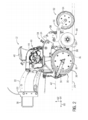
A Figura 3 é uma vista lateral de uma realização de um sistema de distribuição de partícula que pode ser utilizado dentro da unidade de fileira da Figura 2, de acordo com um aspecto da presente divulgação;
A Figura 4 é um fluxograma de uma realização de um processo para controlar um sistema de distribuição de partícula, de acordo com um aspecto da presente divulgação;
A Figura 5 é um fluxograma de uma realização de um processo para controlar um sistema de distribuição de partícula, de acordo com um aspecto da presente divulgação;
A Figura 6 é uma vista lateral de uma outra realização de um sistema de distribuição de partícula que pode ser utilizado dentro da unidade de fileira da Figura 2, de acordo com um aspecto da presente divulgação;
A Figura 7 é um fluxograma de uma outra realização de um processo para controlar um sistema de distribuição de partícula, de acordo com um aspecto da presente divulgação;
A Figura 8 é uma vista lateral de uma realização de um sistema de distribuição de partícula que pode ser utilizado dentro da unidade de fileira da Figura 2, de acordo com um aspecto da presente divulgação;
A Figura 9 é um fluxograma de uma realização de um processo para controlar um sistema de distribuição de partícula, de acordo com um aspecto da presente divulgação; e
A Figura 10 é um fluxograma de uma realização de um processo para controlar um sistema de distribuição de partícula, de acordo com um aspecto da presente divulgação.[006] These and other features, aspects and advantages of the present disclosure will be better understood when the following detailed description is read with reference to the accompanying drawings in which similar characters represent similar parts throughout the drawings, in which:
Figure 1 is a perspective view of an embodiment of an agricultural implement that has multiple row units distributed across a width of the agricultural implement, in accordance with an aspect of the present disclosure;
Figure 2 is a side view of one embodiment of a row unit that may be used in the agricultural implement of Figure 1, in accordance with an aspect of the present disclosure;
Figure 3 is a side view of one embodiment of a particle distribution system that can be used within the row unit of Figure 2, in accordance with an aspect of the present disclosure;
Figure 4 is a flowchart of one embodiment of a process for controlling a particle delivery system, in accordance with an aspect of the present disclosure;
Figure 5 is a flowchart of one embodiment of a process for controlling a particle delivery system, in accordance with an aspect of the present disclosure;
Figure 6 is a side view of another embodiment of a particle distribution system that may be used within the row unit of Figure 2, in accordance with an aspect of the present disclosure;
Figure 7 is a flowchart of another embodiment of a process for controlling a particle delivery system, in accordance with an aspect of the present disclosure;
Figure 8 is a side view of one embodiment of a particle distribution system that may be used within the row unit of Figure 2, in accordance with an aspect of the present disclosure;
Figure 9 is a flowchart of one embodiment of a process for controlling a particle delivery system, in accordance with an aspect of the present disclosure; and
Figure 10 is a flowchart of one embodiment of a process for controlling a particle delivery system, in accordance with an aspect of the present disclosure.
[007] Uma ou mais realizações específicas da presente divulgação serão descritas abaixo. Em um esforço para fornecer uma descrição concisa dessas realizações, todos os recursos de uma implementação real podem não ser descritos no relatório descritivo. Deve ser observado que no desenvolvimento de qualquer implementação real, como em qualquer projeto de engenharia ou projeto, várias decisões específicas de implementação devem ser feitas para atingir os objetivos específicos dos desenvolvedores, como conformidade com restrições relacionadas ao sistema e negócios, que pode variar de uma implementação para outra. Além disso, deve ser observado que tal esforço de desenvolvimento pode ser complexo e demorado, mas seria, no entanto, um empreendimento de rotina de projeto, fabricação e fabricação para aquelas pessoas de habilidade comum que têm o benefício desta divulgação.[007] One or more specific embodiments of the present disclosure will be described below. In an effort to provide a concise description of these achievements, all features of an actual implementation may not be described in the descriptive report. It should be noted that in the development of any actual implementation, as with any engineering project or project, several implementation-specific decisions must be made to achieve the developers' specific goals, such as compliance with system and business-related constraints, which can range from one implementation to another. Furthermore, it should be noted that such a development effort can be complex and time-consuming, but would nevertheless be a routine design, fabrication, and fabrication endeavor for those people of common skill who have the benefit of this disclosure.
[008] Ao introduzir elementos de várias realizações da presente divulgação, os artigos "um”, "uma”, "o”, "a” e "o dito” significam que há um ou mais dos elementos. Os termos "compreendendo”, "incluindo” e "tendo” se destinam a ser inclusivos e significam que pode haver elementos adicionais além dos elementos listados. Quaisquer exemplos de parâmetros operacionais e/ou condições ambientais não são exclusivos de outros parâmetros/condições das realizações divulgadas.[008] In introducing elements from various embodiments of the present disclosure, the articles "a", "an", "the", "the" and "the said" mean that there is one or more of the elements. The terms "comprising", "including" and "having" are intended to be inclusive and mean that there may be additional elements in addition to the elements listed. Any examples of operating parameters and/or environmental conditions are not exclusive of other parameters/conditions of the disclosed achievements.
[009] Certas realizações da presente divulgação incluem um sistema de distribuição de partícula para uma unidade de fileira de um implemento agrícola. Certos implementos agrícolas incluem unidades de fileira configuradas para distribuir partículas (por exemplo, sementes) para valas no solo. Por exemplo, um sistema de distribuição de partícula pode transportar as partículas de um tanque de armazenamento do implemento agrícola para as unidades de fileira (por exemplo, para um conjunto de funil de cada unidade de fileira ou diretamente a um sistema de distribuição de partícula de cada unidade de fileira), e/ou as partículas podem ser distribuídas de um conjunto de funil de cada unidade de fileira para um respectivo sistema de distribuição de partícula. Cada sistema de distribuição de partícula pode enviar as partículas para uma respectiva vala à medida que o implemento agrícola se desloca sobre solo. Certos implementos agrícolas são configurados para se deslocar em velocidades específicas (por exemplo, entre quatro quilômetros por hora (kph) e trinta kph), enquanto distribuem as partículas para as valas. Além disso, um espaçamento específico entre as partículas quando dispostas dentro do solo pode aumentar o desenvolvimento e/ou rendimento da planta.[009] Certain embodiments of the present disclosure include a particle delivery system for a row unit of an agricultural implement. Certain agricultural implements include row units configured to distribute particles (eg seeds) to ditches in the ground. For example, a particle distribution system can transport particles from an agricultural implement storage tank to row units (for example, to a hopper assembly of each row unit or directly to a field particle distribution system. each row unit), and/or particles can be dispensed from a funnel assembly of each row unit to a respective particle distribution system. Each particle distribution system can send particles to a respective ditch as the agricultural implement moves over the ground. Certain agricultural implements are configured to travel at specific speeds (eg, between four kilometers per hour (kph) and thirty kph) while distributing particles to the trenches. In addition, a specific spacing between particles when disposed within the soil can increase plant development and/or yield.
[010] Consequentemente, em certas realizações, pelo menos uma unidade de fileira do implemento agrícola inclui um sistema de distribuição de partícula configurado para distribuir as partículas para a respectiva vala no solo em um espaçamento particular enquanto reduz a velocidade de avanço relativa das partículas (por exemplo, a velocidade das partículas em relação ao solo). O sistema de distribuição de partícula inclui um primeiro disco de partícula configurado para medir partículas individuais, desse modo estabelecendo o espaçamento específico entre as partículas. O primeiro disco de partícula é configurado para liberar cada partícula em um ponto de distribuição do primeiro disco de partícula, desse modo permitindo a partícula se mover para um ponto de engate de um segundo disco de partícula. O segundo disco de partícula é configurado para receber cada partícula no ponto de engate. O segundo disco de partícula também é configurado para transportar cada partícula a partir do ponto de engate para um ponto de distribuição do segundo disco de partícula. O segundo disco de partícula é configurado para acelerar cada partícula, desse modo aumentando a velocidade da partícula no ponto de distribuição, como comparado com o ponto de engate. Por exemplo, o segundo disco de partícula pode acelerar as partículas a uma velocidade maior do que uma velocidade resultante de aceleração gravitacional sozinha. Adicionalmente, o segundo disco de partícula pode acelerar as partículas de modo que o sistema de distribuição de partícula reduza a velocidade de avanço relativa das partículas. Desse modo, o segundo disco de partícula pode permitir que a unidade de fileira se desloque mais rápido do que unidades de fileira tradicionais que utilizam tubos de semente, que dependem da gravidade para acelerar as partículas (por exemplo, sementes) para distribuição ao solo.[010] Consequently, in certain embodiments, at least one row unit of the agricultural implement includes a particle distribution system configured to distribute the particles to the respective ground trench at a particular spacing while reducing the relative speed of advance of the particles ( for example, the velocity of the particles relative to the ground). The particle distribution system includes a first particle disk configured to measure individual particles, thereby establishing the specific spacing between the particles. The first particle disk is configured to release each particle at a distribution point of the first particle disk, thereby allowing the particle to move to an engagement point of a second particle disk. The second particle disk is configured to receive each particle at the point of engagement. The second particle disk is also configured to transport each particle from the point of attachment to a distribution point on the second particle disk. The second particle disk is configured to accelerate each particle, thereby increasing the particle's velocity at the distribution point, as compared to the hitch point. For example, the second particle disk can accelerate particles at a speed greater than a speed resulting from gravitational acceleration alone. Additionally, the second particle disk can accelerate the particles so that the particle distribution system reduces the relative speed of advance of the particles. In this way, the second particle disk can allow the row unit to move faster than traditional row units that use seed tubes, which rely on gravity to accelerate particles (eg, seeds) for distribution to the soil.
[011] Em certas realizações, o sistema de distribuição de partícula pode incluir um sistema de fluxo de ar configurado para prender as partículas ao primeiro disco de partícula e/ou ao segundo disco de partícula, para remover as partículas a partir do primeiro disco de partícula, para acelerar as partículas para baixo a partir do primeiro disco de partícula em direção ao segundo disco de partícula, ou uma combinação dos mesmos. Por exemplo, o sistema de fluxo de ar pode incluir uma fonte de vácuo configurada para reduzir a pressão de ar dentro de uma passagem de vácuo posicionada ao longo de uma porção do primeiro disco de partícula, desse modo prendendo as partículas ao primeiro disco de partícula. Em certas realizações, a fonte de vácuo também pode ser configurada para reduzir a pressão de ar dentro de uma passagem de vácuo posicionada ao longo de uma porção do segundo disco de partícula, desse modo prendendo as partículas ao segundo disco de partícula. Adicionalmente, o sistema de fluxo de ar pode fornecer um fluxo de ar configurado para remover as partículas a partir do primeiro disco de partícula no ponto de distribuição.[011] In certain embodiments, the particle distribution system may include an air flow system configured to secure particles to the first particle disk and/or to the second particle disk to remove particles from the first particle disk. particle, to accelerate particles downward from the first particle disk toward the second particle disk, or a combination thereof. For example, the air flow system can include a vacuum source configured to reduce air pressure within a vacuum passage positioned along a portion of the first particle disk, thereby securing the particles to the first particle disk. . In certain embodiments, the vacuum source can also be configured to reduce air pressure within a vacuum passage positioned along a portion of the second particle disk, thereby trapping particles to the second particle disk. Additionally, the airflow system can provide an airflow configured to remove particles from the first particle disc at the distribution point.
[012] Em algumas realizações, o sistema de distribuição de partícula pode incluir um conjunto de transferência de partícula configurado para facilitar a transferência as partículas a partir do primeiro disco de partícula para o segundo disco de partícula. Por exemplo, o conjunto de transferência de partícula pode incluir uma roda guia disposta entre o primeiro disco de partícula e o segundo disco de partícula e configurado para girar para guiar as partículas a partir do primeiro disco de partícula em direção ao segundo disco de partícula. Em certas realizações, o conjunto de transferência de partícula pode incluir um tubo de partícula que se estende a partir do ponto de distribuição do primeiro disco de partícula para o ponto de engate do segundo disco de partícula e configurado para guiar as partículas a partir do primeiro disco de partícula para o segundo disco de partícula. Em algumas realizações, o conjunto de transferência de partícula pode ser configurado para acelerar as partículas que fluem a partir do primeiro disco de partícula em direção ao segundo disco de partícula.[012] In some embodiments, the particle distribution system may include a particle transfer assembly configured to facilitate the transfer of particles from the first particle disk to the second particle disk. For example, the particle transfer assembly can include a guide wheel disposed between the first particle disk and the second particle disk and configured to rotate to guide particles from the first particle disk toward the second particle disk. In certain embodiments, the particle transfer assembly may include a particle tube extending from the distribution point of the first particle disk to the engagement point of the second particle disk and configured to guide particles from the first. particle disk to the second particle disk. In some embodiments, the particle transfer assembly can be configured to accelerate particles flowing from the first particle disk toward the second particle disk.
[013] Com o exposto em mente, as presentes realizações se referem aos sistemas de distribuição de partículas podem ser utilizadas em qualquer implemento agrícola adequado. Por exemplo, a Figura 1 é uma vista em perspectiva de uma realização de um implemento agrícola 10 tendo várias unidades de fileira 12 distribuídas ao longo de uma largura do implemento agrícola 10. O implemento 10 está configurado para ser rebocado através de um campo atrás de um veículo de trabalho, como um trator. Conforme ilustrado, o implemento 10 inclui um conjunto de lingueta 14, que inclui um engate configurado para acoplar o implemento 10 a um engate de trator apropriado (por exemplo, por meio de uma esfera, forquilha ou outro acoplamento). O conjunto de lingueta 14 é acoplado a uma barra de ferramentas 16 que suporta várias unidades de fileira 12. Cada unidade de fileira 12 pode incluir um ou mais discos de abertura configurados para formar um caminho de partículas (por exemplo, vala) dentro do solo de um campo. A unidade de fileira 12 também pode incluir um sistema de distribuição de partículas (por exemplo, discos de partículas) configurado para depositar partículas (por exemplo, sementes, fertilizantes e/ou outro(s) produto(s) agrícola(s)) no caminho/vala das partículas. Além disso, a unidade de fileira 12 pode incluir disco(s) de fechamento e/ou uma roda de compressão posicionada atrás do sistema de distribuição de partículas. O(s) disco(s) de fechamento é(são) configurado(s) para mover o solo deslocado de volta para o caminho/vala das partículas e a roda de compressão é configurada para compactar o solo no topo das partículas depositadas.[013] With the foregoing in mind, the present embodiments refer to particle distribution systems that can be used in any suitable agricultural implement. For example, Figure 1 is a perspective view of an embodiment of an agricultural implement 10 having
[014] Durante a operação, o implemento agrícola 10 pode se deslocar em uma velocidade específica ao longo da superfície do solo enquanto deposita as partículas nas valas. Por exemplo, uma velocidade do implemento agrícola pode ser selecionada e/ou controlada com base nas condições do solo, um tipo das partículas distribuídas pelo implemento agrícola 10 no solo, condições climáticas, um tamanho/tipo do implemento agrícola, ou uma combinação dos mesmos. Além disso ou alternativamente, um espaçamento específico entre as partículas quando dispostas dentro do solo pode aumentar o desenvolvimento e/ou rendimento da planta. Consequentemente, em certas realizações, pelo menos uma unidade de fileira 12 pode incluir um sistema de distribuição de partícula configurado para depositar as partículas no espaçamento específico enquanto reduz a velocidade de avanço das partículas (por exemplo, em comparação com uma unidade de fileira que emprega um tubo de partícula para distribuir partículas ao solo). Conforme discutido em detalhes abaixo, o sistema de distribuição de partícula pode incluir um primeiro disco de partícula configurado para medir partículas individuais para um segundo disco de partícula para estabelecer o espaçamento entre as partículas. Adicionalmente, o segundo disco de partícula pode receber as partículas e mover e acelerar as partículas em direção à vala no solo. O segundo disco de partícula pode acelerar as partículas a uma velocidade maior do que uma velocidade resultante de aceleração gravitacional sozinha (por exemplo, uma velocidade resultante da partícula caindo diretamente do primeiro disco no solo com o segundo disco omitido) e pode reduzir a velocidade de avanço relativa das partículas (por exemplo, a velocidade das partículas em relação ao solo). Em certas realizações, o sistema de distribuição de partícula pode incluir disco(s) de partícula adicional(s) (por exemplo, um terceiro disco de partícula) e/ou uma correia de partícula configurada para acelerar progressivamente as partículas. Desse modo, o sistema de distribuição de partícula pode permitir que a unidade de fileira 12 se desloque mais rápido do que unidades de fileira tradicionais que utilizam tubos de semente, que dependem da gravidade para acelerar as partículas (por exemplo, sementes) para distribuição ao solo. Como um resultado, o implemento agrícola 10 pode se deslocar mais rápido através do campo e colocar com mais precisão cada partícula dentro do solo do campo.[014] During operation, the agricultural implement 10 can travel at a specific speed along the soil surface while depositing the particles in the trenches. For example, a speed of the agricultural implement can be selected and/or controlled based on soil conditions, a type of particles distributed by the agricultural implement 10 in the soil, weather conditions, a size/type of agricultural implement, or a combination thereof . Additionally or alternatively, specific spacing between particles when disposed within the soil can increase plant development and/or yield. Accordingly, in certain embodiments, at least one
[015] A Figura 2 é uma vista lateral de uma realização de uma unidade de fileira 12 (por exemplo, unidade de fileira agrícola) que pode ser utilizada no implemento agrícola da Figura 1. A unidade de fileira 12 inclui uma montagem 18 configurada para prender a unidade de fileira 12 à barra de ferramenta do implemento agrícola. Na realização ilustrada, a montagem 18 inclui um parafuso em U que prende um suporte 20 da unidade de fileira 12 à barra de ferramenta. Entretanto, em realizações alternativas, a montagem pode incluir um outro dispositivo adequado que acopla a unidade de fileira à barra de ferramenta. Um conjunto de ligação 22 se estende a partir do suporte 20 para uma estrutura 24 da unidade de fileira 12. O conjunto de ligação 22 é configurado para permitir o movimento vertical da estrutura 24 em relação à barra de ferramenta em resposta às variações em uma superfície do solo 26. Em certas realizações, um sistema de pressão descendente (por exemplo, incluindo um atuador hidráulico, um atuador pneumático, etc.) pode ser acoplado ao conjunto de ligação 22 e configurado para impelir a estrutura 24 em direção à superfície do solo 26. Enquanto o conjunto de ligação ilustrado 22 é um conjunto de ligação paralelo (por exemplo, um conjunto de ligação de quatro barras), em realizações alternativas, um outro conjunto de ligação adequado pode se estender entre o suporte e a estrutura.[015] Figure 2 is a side view of an embodiment of a 12 row unit (e.g. agricultural row unit) that may be used in the agricultural implement of Figure 1.
[016] A unidade de fileira 12 inclui um conjunto abridor 30 que forma uma vala 31 na superfície do solo 26 para a deposição de partículas no solo. Na realização ilustrada, o conjunto abridor 30 inclui rodas reguladoras 32, braços 34 que se acoplam de forma articulável às rodas reguladoras 32 à estrutura 24, e discos abridores 36. Os discos abridores 36 são configurados para escavar a vala 31 no solo, e as rodas reguladoras 32 são configuradas para controlar uma profundidade de penetração dos discos abridores 36 no solo. Na realização ilustrada, a unidade de fileira 12 inclui um sistema de controle de profundidade 38 configurado para controlar a posição vertical das rodas reguladoras 32 (por exemplo, bloqueando a rotação dos braços na direção para cima além de uma orientação selecionada), desse modo controlando a profundidade de penetração dos discos abridores 36 no solo.[016] The
[017] A unidade de fileira 12 inclui um sistema de distribuição de partícula 40 configurado para depositar partículas (por exemplo, sementes, fertilizante, e/ou outro(s) produto(s) agrícola(s)) na vala 31 à medida que a unidade de fileira 12 atravessa o campo ao longo de uma direção de deslocamento 42. Conforme ilustrado, o sistema de distribuição de partícula 40 inclui uma unidade de medição e individualização de partícula 44 configurada para receber as partículas (por exemplo, sementes) de um conjunto de funil 46 (por exemplo, uma área de armazenamento de partícula). Em certas realizações, um funil do conjunto de funil pode ser integralmente formado com um alojamento da unidade de medição e individualização de partícula. O conjunto de funil 46 é configurado para armazenar as partículas para medição subsequente pela unidade de medição e individualização de partícula 44. Como será descrito em mais detalhes abaixo, em algumas realizações, a unidade de medição e individualização de partícula 44 inclui um disco de partícula configurado para girar para transferir as partículas do conjunto de funil 46 em direção a um segundo disco de partícula do sistema de distribuição de partícula 40. O segundo disco de partícula do sistema de distribuição de partícula 40 pode geralmente estar disposto entre a unidade de medição e individualização de partícula 44 e a vala 31 e pode transferir as partículas recebidas da unidade de medição e individualização de partícula 44 para a vala 31. Em algumas realizações, o sistema de distribuição de partícula pode incluir uma correia de partícula disposta geralmente entre o segundo disco de partícula e a vala. Por exemplo, a correia de partícula pode receber as partículas do segundo disco de partícula e distribuir as partículas para a vala.[017]
[018] O conjunto abridor 30 e o sistema de distribuição de partícula 40 são seguidos por um conjunto de fechamento 48 que move o solo deslocado de volta para a vala 31. Na realização ilustrada, o conjunto de fechamento 48 inclui dois discos de fechamento 50. Entretanto, em realizações alternativas, o conjunto de fechamento pode incluir outros dispositivos de fechamento (por exemplo, um único disco de fechamento, etc.). Além disso, em certas realizações, o conjunto de fechamento pode ser omitido. Na realização ilustrada, o conjunto de fechamento 48 é seguido por um conjunto de compressão 52 configurado para comprimir o solo no topo das partículas depositadas. O conjunto de compressão 52 inclui uma roda de compressão 54, um braço 56 que acopla de maneira articulável a roda de compressão 54 à estrutura 24, e um elemento tensionador 58 configurado para impelir a roda de compressão 54 em direção à superfície do solo 26, desse modo fazendo a roda de compressão comprimir o solo no topo das partículas depositadas (por exemplo, sementes e/ou outro(s) produto(s) agrícola(s)). Enquanto o elemento tensionador ilustrado 58 inclui uma mola, em realizações alternativas, o elemento tensionador pode incluir um outro dispositivo tensionador adequado, tal como um cilindro hidráulico ou um cilindro pneumático, entre outros. Para propósitos de debate, a referência pode ser feita a um eixo ou direção longitudinal 60, um eixo ou direção vertical 62, e um eixo ou direção lateral 64. Por exemplo, a direção de deslocamento 42 da unidade de fileira 12 pode ser geralmente ao longo do eixo longitudinal 60.[018] The
[019] A Figura 3 é uma vista lateral de uma realização de um sistema de distribuição de partícula 40 que pode ser utilizado dentro da unidade de fileira da Figura 2. Como descrito acima, o sistema de distribuição de partícula 40 é configurado para medir e acelerar partículas 80 (por exemplo, sementes, fertilizante, outro material particulado, ou uma combinação dos mesmos) em direção à vala 31 para deposição na vala 31. Na realização ilustrada, o sistema de distribuição de partícula 40 inclui um primeiro disco de partícula 82 (por exemplo, da unidade de medição e individualização de partícula 44) configurado para medir as partículas 80 e um segundo disco de partícula 84 configurado para acelerar e mover as partículas 80 em direção à vala 31 para deposição na vala 31.[019] Figure 3 is a side view of an embodiment of a
[020] O primeiro disco de partícula 82 tem aberturas 90 configuradas para receber as partículas 80 de um funil de partícula 92 do sistema de distribuição de partícula 40. Por exemplo, cada abertura 90 pode receber uma única partícula 80. O funil de partícula 92 é uma área de armazenamento de partícula configurada para armazenar as partículas 80 para medição e distribuição subsequente. Em certas realizações, o funil de partícula 92 pode ser acoplado a e/ou incluído como parte de um alojamento da unidade de medição e individualização de partícula 44. Além disso, em algumas realizações, o conjunto de funil pode fornecer as partículas 80 para o funil de partícula 92, e/ou o conjunto de funil (por exemplo, o funil do conjunto de funil) pode ser acoplado ao funil de partícula 92. O primeiro disco de partícula 82 é configurado para girar, como indicado pela seta 94, para mover as partículas 80 do funil de partícula 92 para um ponto de distribuição 96, onde as partículas 80 são liberadas para baixo em direção ao segundo disco de partícula 84.[020] The
[021] Conforme ilustrado, o sistema de distribuição de partícula 40 inclui um sistema de fluxo de ar 100 tendo um dispositivo de fluxo de ar 102 (por exemplo, uma fonte de vácuo), um primeiro tubo de ar 104 fluidamente acoplado ao dispositivo de fluxo de ar 102, um segundo tubo de ar 106 fluidamente acoplado ao dispositivo de fluxo de ar 102, e um terceiro tubo de ar 108 fluidamente acoplado ao dispositivo de fluxo de ar 102. O sistema de fluxo de ar 100 é configurado para reduzir a pressão de ar dentro de uma primeira passagem de vácuo 110 posicionada ao longo de uma porção do primeiro disco de partícula 82, desse modo puxando as partículas 80 do funil de partícula 92 em direção e contra as aberturas 90. Conforme ilustrado, o primeiro tubo de ar 104 é fluidamente acoplado ao dispositivo de fluxo de ar 102 e à primeira passagem de vácuo 110. O dispositivo de fluxo de ar 102 é configurado para puxar o ar através das aberturas 90 enquanto as aberturas 90 são alinhadas com a primeira passagem de vácuo 110. Como o primeiro disco de partícula 82 gira, o vácuo formado nas aberturas 90 prende as partículas 80 ao primeiro disco de partícula 82 nas aberturas 90, de modo que o primeiro disco de partícula 82 move cada partícula 80 do funil de partícula 92 para o ponto de distribuição 96. No ponto de distribuição 96, o sistema de fluxo de ar 100 fornece, por meio do segundo tubo de ar 106, um fluxo de ar 112 configurado para remover cada partícula 80 da respectiva abertura 90 (por exemplo, ao superar o vácuo formado nas aberturas 90). Em certas realizações, o fluxo de ar 112 pode ser omitido, e as partículas 80 podem ser liberadas das aberturas 90 devido à primeira passagem de vácuo 110 terminando. Por exemplo, no ponto de distribuição 96, a primeira passagem de vácuo 110 pode terminar (por exemplo, o dispositivo de fluxo de ar 102 pode não puxar mais o ar através das aberturas 90 do primeiro disco de partícula 82 no ponto de distribuição 96), e as partículas 80 podem não ser mais presas nas aberturas 90. As partículas 80 são liberadas a partir do primeiro disco de partícula 82 ao longo de uma trajetória de distribuição 114. A rotação do primeiro disco de partícula 82 transmite uma velocidade nas partículas ao longo da trajetória de distribuição 114, e as partículas 80 aceleram para baixo ao longo da trajetória de distribuição 114 sob a influência da gravidade. Em algumas realizações, um ângulo entre a trajetória de distribuição 114 e o eixo vertical 62 pode ser zero graus, um grau, dois graus, cinco graus, dez graus, vinte graus, ou outros ângulos adequados. Como usado aqui, "vácuo” se refere a uma pressão de ar que é menor do que a pressão de ar atmosférico ambiente, e não necessariamente 0 pa.[021] As illustrated, the
[022] O sistema de distribuição de partícula 40 inclui um primeiro alojamento de disco 120 e um segundo alojamento de disco 122. O primeiro disco de partícula 82 é disposto dentro de e configurado para girar dentro do primeiro alojamento de disco 120. O segundo disco de partícula 84 é disposto e configurado para girar dentro do segundo alojamento de disco 122. A primeira passagem de vácuo 110 da unidade de medição e individualização de partícula 44 é formada dentro do primeiro alojamento de disco 120. Adicionalmente, a unidade de medição e individualização de partícula 44 inclui o primeiro disco de partícula 82 e o primeiro alojamento de disco 120. Adicionalmente, o funil de partícula 92 (por exemplo, a área de armazenamento de partícula) é formado dentro do primeiro alojamento de disco 120.[022] The
[023] Conforme ilustrado, o sistema de distribuição de partícula 40 inclui um conjunto de transferência de partícula 130 tendo um tubo de partícula 131 que se estende geralmente a partir do ponto de distribuição 96 para um ponto de engate 132 do segundo disco de partícula 84. O tubo de partícula 131 do conjunto de transferência de partícula 130 é acoplado ao primeiro alojamento de disco 120 e ao segundo alojamento de disco 122. O segundo disco de partícula 84 é configurado para receber cada partícula 80 no ponto de engate 132. o conjunto de transferência de partícula 130 é configurado para pelo menos direcionar parcialmente as partículas 80 a partir do primeiro disco de partícula 82 (por exemplo, a partir do ponto de distribuição 96 do primeiro disco de partícula 82) ao segundo disco de partícula 84 (por exemplo, para o ponto de engate 132 do segundo disco de partícula 84) ao longo da trajetória de distribuição 114. Em certas realizações, o conjunto de transferência de partícula pode ser omitido, tal que as partículas fluem a partir do ponto de distribuição para o ponto de engate sem o conjunto de transferência de partícula. O tubo de partícula pode incluir qualquer formato e/ou configuração adequado configurado para, pelo menos, a partícula direcionar as partículas, como um canal, um tubo cilíndrico, um tubo retangular e/ou outros formatos/configurações adequados.[023] As illustrated, the
[024] O segundo disco de partícula 84 tem aberturas 134 configuradas para receber as partículas 80 no ponto de engate 132. Por exemplo, cada abertura 134 pode receber uma única partícula 80. O segundo disco de partícula 84 é configurado para girar, como indicado pela seta 136, para mover as partículas 80 a partir do ponto de engate 132 para um ponto de distribuição 138 do segundo disco de partícula 84, onde as partículas 80 são liberadas ao longo de uma trajetória de distribuição 140 em direção à vala 31.[024] The
[025] O sistema de fluxo de ar 100 é configurado para reduzir a pressão de ar dentro de uma segunda passagem de vácuo 150 posicionada ao longo de uma porção do segundo disco de partícula 84, desse modo puxando as partículas 80 em direção e nas aberturas 134 no ponto de engate 132. Conforme ilustrado, o terceiro tubo de ar 108 é fluidamente acoplado ao dispositivo de fluxo de ar 102 e à segunda passagem de vácuo 150 formada dentro do segundo alojamento de disco 122. O dispositivo de fluxo de ar 102 é configurado para puxar o ar através das aberturas 134 enquanto as aberturas 134 são alinhadas com a segunda passagem de vácuo 150. Como o segundo disco de partícula 84 gira, o vácuo formado nas aberturas 134 prende as partículas 80 ao segundo disco de partícula 84 nas aberturas 134, de modo que o segundo disco de partícula 84 move cada partícula 80 a partir do ponto de engate 132 para o ponto de distribuição 138. No ponto de distribuição 96, a segunda passagem de vácuo 150 termina (por exemplo, o vácuo é removido, terminado, e/ou ocluído), e as partículas 80 são liberadas das aberturas 134 do segundo disco de partícula 84 ao longo da trajetória de distribuição 140. Em certas realizações, além de ou em vez de remover o vácuo (por exemplo, a segunda passagem de vácuo terminando), o sistema de fluxo de ar pode ser configurado para remover as partículas do disco de partícula por meio de um fluxo de ar. O sistema de fluxo de ar pode ser configurado para acelerar as partículas do segundo disco de partícula em direção à vala como as partículas são removidas do segundo disco de partícula. Em certas realizações, o sistema de distribuição de partícula pode incluir um primeiro dispositivo de fluxo de ar (por exemplo, uma primeira fonte de vácuo) configurado para formar o vácuo ao longo da primeira passagem de vácuo para prender as partículas ao primeiro disco de partícula, e um segundo dispositivo de fluxo de ar (por exemplo, uma segunda fonte de vácuo) configurado para formar o vácuo ao longo da segunda passagem de vácuo para prender as partículas ao segundo disco de partícula.[025] The
[026] Como descrito acima, o primeiro disco de partícula 82 é configurado para medir as partículas 80 e para fornecer um espaçamento entre as partículas 80. O espaçamento entre as partículas 80 quando dispostas dentro da vala 31 pode aumentar o desenvolvimento e/ou rendimento da planta. Adicionalmente, o sistema de distribuição de partícula 40 é configurado para acelerar as partículas 80 geralmente em direção e ao longo da vala 31. A aceleração das partículas 80 pelo sistema de distribuição de partícula 40 pode permitir que a unidade de fileira se desloque mais rápido do que unidades de fileira tradicionais que utilizam tubos de semente, que dependem somente da gravidade para acelerar as partículas 80 para distribuição ao solo. Por exemplo, o sistema de distribuição de partícula 40 pode atingir taxas de aplicação mais altas das partículas 80 em comparação com unidades de fileira tradicionais, desse modo permitindo a unidade de fileira tenha o sistema de distribuição de partícula 40 para se deslocar mais rápido do que unidades de fileira tradicionais. O sistema de distribuição de partícula 40 é configurado para acelerar as partículas 80 por meio do sistema de fluxo de ar 100, gravidade, e o segundo disco de partícula 84. Por exemplo, o sistema de fluxo de ar 100 é configurado para fornecer o fluxo de ar 112 do segundo tubo de ar 106 para acelerar as partículas 80 para baixo ao longo da trajetória de distribuição 114. Por exemplo, o sistema de fluxo de ar 100 pode aplicar uma força às partículas 80 por meio do fluxo de ar 112. Adicionalmente, o sistema de distribuição de partícula 40 é configurado para permitir que as partículas 80 acelerem sob a influência da gravidade à medida que as partículas 80 se deslocam entre o primeiro disco de partícula 82 e o segundo disco de partícula 84. O segundo disco de partícula 84 é configurado para acelerar as partículas 80 recebidas a partir do primeiro disco de partícula 82, de modo que uma velocidade de saída de partícula das partículas 80 expelidas do segundo disco de partícula 84 ao longo da trajetória de distribuição 140 atinja uma velocidade de saída de partícula alvo. A velocidade de saída de partícula das partículas 80 pode atingir a velocidade de saída de partícula alvo quando a velocidade de saída de partícula é igual à velocidade de saída de partícula alvo, quando a velocidade de saída de partícula passa (por exemplo, é maior do que ou menor do que) a velocidade de saída de partícula alvo, quando a velocidade de saída de partícula está dentro de um valor limite da velocidade de saída de partícula alvo, ou uma combinação dos mesmos.[026] As described above, the
[027] Em certas realizações, o segundo disco de partícula 84 é configurado para girar mais rápido do que o primeiro disco de partícula 82 para acelerar as partículas 80. Por exemplo, o primeiro disco de partícula 82 pode girar em uma primeira velocidade (por exemplo, uma primeira velocidade tangencial do primeiro disco de partícula 82 nas aberturas 90), e o segundo disco de partícula 84 pode girar em uma segunda velocidade (por exemplo, uma segunda velocidade tangencial do segundo disco de partícula 84 nas aberturas 134) mais rápido do que a primeira velocidade. A velocidade mais rápido do segundo disco de partícula 84 pode acelerar as partículas 80 para a velocidade de saída de partícula alvo à medida que as partículas 80 são liberadas do segundo disco de partícula 84.[027] In certain embodiments, the
[028] Em algumas realizações, o segundo disco de partícula 84 pode ter um raio maior do que o primeiro disco de partícula 82. Como usado aqui, raio se refere à distância radial de um centro de um disco de partícula para as aberturas do disco de partícula. Por exemplo, um primeiro raio do primeiro disco de partícula 82 pode ser uma distância radial entre um centro do primeiro disco de partícula 82 e as aberturas 90, e um segundo raio do segundo disco de partícula 84 pode ser uma distância radial entre um centro do segundo disco de partícula 84 e as aberturas 134. O raio maior do segundo disco de partícula 84 pode acelerar as partículas 80 (por exemplo, mesmo se o primeiro e segundo discos de partículas estiverem girando na mesma velocidade rotacional). Por exemplo, a velocidade tangencial do segundo disco de partícula 84 nas aberturas 134 pode ser maior do que a velocidade tangencial do primeiro disco de partícula 82 nas aberturas 90, porque uma distância radial das aberturas 134 é maior do que uma distância radial das aberturas 90.[028] In some embodiments, the
[029] Em certas realizações, o sistema de distribuição de partícula pode incluir discos de partícula adicionais (por exemplo, além do primeiro disco de partícula 82 e do segundo disco de partícula 84) configurados para acelerar as partículas em direção e/ou ao longo da vala. Cada disco de partícula (do disco de partícula adjacente ao funil para o disco de partícula adjacente para a vala) pode girar progressivamente mais rápido e/ou pode ter raios progressivamente maiores, de modo que cada disco de partícula progressivo transmita uma maior velocidade em cada partícula à medida que a partícula é liberada do respectivo disco de partícula.[029] In certain embodiments, the particle distribution system may include additional particle disks (e.g., in addition to the
[030] O sistema de distribuição de partícula 40 inclui um controlador 170 configurado para controlar a taxa de rotação (por exemplo, a velocidade rotacional) do primeiro disco de partícula 82 para ajustar/controlar o espaçamento entre as partículas 80. Por exemplo, o controlador 170 pode controlar um motor 171, que é configurado para acionar a rotação do primeiro disco de partícula 82, para ajustar/controlar a taxa de rotação do primeiro disco de partícula 82 (por exemplo, emitindo um sinal de saída para o motor 171 indicativo de instruções para ajustar a taxa de rotação do primeiro disco de partícula 82). Adicionalmente, o controlador 170 pode controlar o motor 171 para atingir um espaçamento alvo entre as partículas 80. O controlador 170 pode determinar o espaçamento alvo entre as partículas 80 com base em um tipo das partículas 80, uma entrada recebida de uma interface de usuário, e/ou uma velocidade de avanço da unidade de fileira. O espaçamento pode ser qualquer espaçamento adequado, como um centímetro, dois centímetros, cinco centímetros, dez centímetros, cinquenta centímetros, um metro, dois metros, cinco metros, etc. Em certas realizações, o controlador 170 pode controlar a taxa de rotação do primeiro disco de partícula 82 (por exemplo, por meio de controle do motor 171) para atingir o espaçamento alvo com base em uma tabela de referência que identifica as velocidades de rotação do primeiro disco de partícula 82 que irá atingir espaçamentos particulares, com base em uma fórmula empírica, em resposta ao feedback do sensor, ou uma combinação dos mesmos.[030] The
[031] Adicionalmente, o controlador 170 é configurado para controlar a taxa de rotação (por exemplo, velocidade rotacional) do segundo disco de partícula 84 para ajustar/controlar a velocidade de saída de partícula das partículas 80 expelidas do segundo disco de partícula 84 (por exemplo, a partir do ponto de distribuição 138 do segundo disco de partícula 84, ao longo da trajetória de distribuição 140, e em direção e/ou ao longo da vala 31), de modo que a velocidade de saída de partícula atinja uma velocidade de saída de partícula alvo. Por exemplo, o controlador 170 pode controlar um motor 173, que é configurado para acionar a rotação do segundo disco de partícula 84, para ajustar/controlar a taxa de rotação do segundo disco de partícula 84 (por exemplo, emitindo um sinal de saída para o motor 173 indicativo de instruções para ajustar a taxa de rotação do segundo disco de partícula 84), desse modo permitindo ao controlador 170 ajustar/controlar a velocidade de saída de partícula das partículas 80. O controlador 170 pode controlar a velocidade de saída de partícula das partículas 80, de modo que a velocidade de saída de partícula atinja a velocidade de saída de partícula alvo. O controlador 170 pode determinar a velocidade de saída de partícula alvo das partículas 80 com base no tipo das partículas 80, uma entrada recebida de uma interface de usuário, e/ou a velocidade de avanço da unidade de fileira. A velocidade de saída de partícula alvo pode ser qualquer velocidade adequada, tal um quilômetro por hora (kph), dois kph, três kph, cinco kph, dez kph, quinze kph, vinte kph, etc. Em certas realizações, o controlador 170 pode determinar a velocidade de saída de partícula alvo como um porcentagem alvo da velocidade de avanço da unidade de fileira (por exemplo, trinta por cento, cinquenta por cento, setenta por cento, oitenta por cento, noventa por cento, noventa e cinco por cento, cem por cento, etc.).[031] Additionally,
[032] Para controlar a taxa de rotação do segundo disco de partícula 84, o controlador 170 pode receber um sinal de entrada indicativo da velocidade de saída de partícula da partícula 80 no ponto de distribuição 138 do segundo disco de partícula 84. Por exemplo, o controlador 170 pode receber o sinal de entrada de um sensor de partícula 176 do sistema de distribuição de partícula 40 disposto adjacente ao ponto de distribuição 138 e ao longo da trajetória de distribuição 140. A velocidade de saída de partícula pode ser uma velocidade de saída de partícula de uma ou mais partículas 80 (por exemplo, uma média, uma mediana, um mínimo ou um máximo de velocidades de saída de partícula de uma ou mais partículas 80). O sensor de partícula 176 pode incluir um sensor infravermelho ou um outro tipo adequado de sensor configurado para emitir o sinal de entrada indicativo da velocidade de saída de partícula de cada partícula 80 no ponto de distribuição 138. O sensor de partícula 176 pode ser posicionado a uma distância fixa a partir do ponto de distribuição 138 do segundo disco de partícula 84, de modo que o controlador 170 possa determinar a velocidade de saída de partícula da partícula 80 no ponto de distribuição 138 com base na distância fixa e no sinal de entrada indicativo da velocidade de saída de partícula recebida do sensor de partícula 176 (por exemplo, com base na desaceleração da partícula 80 se deslocando na distância fixa).[032] To control the rotation rate of the
[033] O controlador 170 pode comparar a velocidade de saída de partícula da partícula 80 no ponto de distribuição 138 do segundo disco de partícula 84 à velocidade de saída de partícula alvo para determinar se uma diferença entre a velocidade de saída de partícula e a velocidade de saída de partícula alvo excede um valor limite. Em resposta à determinação de que a velocidade de saída de partícula no ponto de distribuição 138 do segundo disco de partícula 84 é menor do que a velocidade de saída de partícula alvo e a diferença entre a velocidade de saída de partícula e a velocidade de saída de partícula alvo excede o valor limite, o controlador 170 pode enviar um sinal de saída indicativo de instruções para aumentar a taxa de rotação do segundo disco de partícula 84. Por exemplo, o controlador 170 pode enviar o sinal de saída para o motor 173 para fazer o motor 173 aumentar a taxa de rotação do segundo disco de partícula 84. O aumento na taxa de rotação do segundo disco de partícula 84 pode aumentar a velocidade de saída de partícula, de modo que a velocidade de saída de partícula atinja a velocidade de saída de partícula alvo (por exemplo, de modo que a diferença entre a velocidade de saída de partícula e a velocidade de saída de partícula alvo seja menor do que o valor limite).[033] The
[034] Em resposta à determinação de que a velocidade de saída de partícula no ponto de distribuição 138 do segundo disco de partícula 84 é maior do que a velocidade de saída de partícula alvo e a diferença entre a velocidade de saída de partícula e a velocidade de saída de partícula alvo excede o valor limite, o controlador 170 pode enviar um sinal de saída indicativo de instruções para diminuir a taxa de rotação do segundo disco de partícula 84. Por exemplo, o controlador 170 pode enviar o sinal de saída para o motor 173 para fazer o motor 173 diminuir a taxa de rotação do segundo disco de partícula 84. A diminuição na taxa de rotação do segundo disco de partícula 84 pode diminuir a velocidade de saída de partícula, de modo que a velocidade de saída de partícula atinja a velocidade de saída de partícula alvo (por exemplo, de modo que a diferença entre a velocidade de saída de partícula e a velocidade de saída de partícula alvo seja menor do que o valor limite).[034] In response to the determination that the particle exit velocity at the
[035] Em certas realizações, o controlador 170 é configurado para controlar o fluxo de ar 112 fornecido pelo sistema de fluxo de ar 100 para ajustar/controlar uma velocidade de transferência de partícula de cada partícula 80 expelida a partir do primeiro disco de partícula 82 (por exemplo, a partir do ponto de distribuição 96 do primeiro disco de partícula 82, ao longo da trajetória de distribuição 114, e em direção ao ponto de engate 132 do segundo disco de partícula 84), de modo que a velocidade de transferência de partícula atinja uma velocidade de transferência de partícula alvo no ponto de engate 132 do segundo disco de partícula 84. Por exemplo, o controlador 170 pode controlar o dispositivo de fluxo de ar 102, que é configurado para fornecer o fluxo de ar 112 para acelerar cada partícula 80 ao longo da trajetória de distribuição 114. O controlador 170 pode determinar a velocidade de transferência de partícula alvo das partículas 80 com base na taxa de rotação do segundo disco de partícula 84 e/ou no tipo das partículas 80. A velocidade de transferência de partícula alvo pode ser qualquer velocidade adequada, tal um décimo kph, meio kph, um kph, dois kph, três kph, cinco kph, dez kph, quinze kph, vinte kph, etc. Em certas realizações, o controlador 170 pode determinar a velocidade de transferência de partícula alvo como uma porcentagem alvo da taxa de rotação do segundo disco de partícula 84 (por exemplo, trinta por cento, cinquenta por cento, setenta por cento, oitenta por cento, noventa por cento, noventa e cinco por cento, cem por cento, etc.).[035] In certain embodiments,
[036] Para controlar o fluxo de ar 112 fornecido pelo sistema de fluxo de ar 100, o controlador 170 pode receber um sinal de entrada indicativo da velocidade de transferência de partícula da partícula 80 no ponto de engate 132 do segundo disco de partícula 84. Por exemplo, o controlador 170 pode receber o sinal de entrada de um sensor de partícula 178 do sistema de distribuição de partícula 40 disposto dentro do conjunto de transferência de partícula 130. A velocidade de transferência de partícula pode ser uma velocidade de transferência de partícula de uma ou mais partículas 80 (por exemplo, uma média, uma mediana, um mínimo ou um máximo de velocidades de transferência de partícula de uma ou mais partículas 80). O sensor de partícula 178 pode incluir um sensor infravermelho ou um outro tipo adequado de sensor configurado para emitir o sinal de entrada indicativo da velocidade de transferência de partícula de cada partícula 80 no ponto de engate 132. O sensor de partícula 178 pode ser posicionado a uma distância fixa a partir do ponto de engate 132 do segundo disco de partícula 84, de modo que o controlador 170 possa determinar a velocidade de transferência de partícula da partícula 80 no ponto de engate 132 com base na distância fixa e no sinal de entrada indicativo da velocidade de transferência de partícula recebida do sensor de partícula 178 (por exemplo, com base na aceleração gravitacional da partícula 80 se deslocando na distância fixa do sensor de partícula 178 para o ponto de engate 132 do segundo disco de partícula 84).[036] To control the
[037] O controlador 170 pode comparar a velocidade de transferência de partícula da partícula 80 no ponto de engate 132 do segundo disco de partícula 84 à velocidade de transferência de partícula alvo para determinar se uma diferença entre a velocidade de transferência de partícula e a velocidade de transferência de partícula alvo excede um valor limite. Em resposta à determinação de que a velocidade de transferência de partícula no ponto de engate 132 do segundo disco de partícula 84 é menor do que a velocidade de transferência de partícula alvo e a diferença entre a velocidade de transferência de partícula e a velocidade de transferência de partícula alvo excede o valor limite, o controlador 170 pode enviar um sinal de saída indicativo de instruções para aumentar a taxa de fluxo do fluxo de ar 112 fornecido pelo sistema de fluxo de ar 100 do segundo tubo de ar 106. Por exemplo, o controlador 170 pode enviar o sinal de saída para o dispositivo de fluxo de ar 102 para fazer o dispositivo de fluxo de ar 102 aumentar a taxa de fluxo do fluxo de ar 112. O aumento na taxa de fluxo de ar pode aumentar a velocidade de transferência de partícula, de modo que a velocidade de transferência de partícula atinja a velocidade de transferência de partícula alvo (por exemplo, de modo que a diferença entre a velocidade de transferência de partícula e a velocidade de transferência de partícula alvo seja menor do que o valor limite).[037] The
[038] Em resposta à determinação de que a velocidade de transferência de partícula no ponto de engate 132 do segundo disco de partícula 84 é maior do que a velocidade de transferência de partícula alvo e a diferença entre a velocidade de transferência de partícula e a velocidade de transferência de partícula alvo excede o valor limite, o controlador 170 pode enviar um sinal de saída indicativo de instruções para diminuir a taxa de fluxo do fluxo de ar 112 fornecido pelo sistema de fluxo de ar 100. Por exemplo, o controlador 170 pode enviar o sinal de saída para o dispositivo de fluxo de ar 102 para fazer o dispositivo de fluxo de ar 102 diminuir a taxa de fluxo do fluxo de ar 112. A diminuição na taxa de fluxo de ar pode diminuir a velocidade de transferência de partícula, de modo que a velocidade de transferência de partícula atinja a velocidade de transferência de partícula alvo (por exemplo, de modo que a diferença entre a velocidade de transferência de partícula e a velocidade de transferência de partícula alvo seja menor do que o valor limite).[038] In response to the determination that the particle transfer rate at the
[039] Conforme ilustrado, o controlador 170 do sistema de distribuição de partícula 40 inclui um processador 190 e uma memória 192. O processador 190 (por exemplo, um microprocessador) pode ser usado para executar software, como software armazenado na memória 192 para controlar o sistema de distribuição de partícula 40 (por exemplo, para controlar velocidades rotacionais do primeiro disco de partícula 82 e do segundo disco de partícula 84, e do fluxo de ar 112 fornecido pelo sistema de fluxo de ar 100). Além disso, o processador 190 pode incluir múltiplos microprocessadores, um ou mais microprocessadores de "uso geral”, um ou mais microprocessadores de uso especial e/ou um ou mais circuitos integrados específicos de aplicação (ASICS), ou alguma combinação dos mesmos. Por exemplo, o processador 190 pode incluir um ou mais processadores de conjunto de instruções reduzidas (RISC) ou conjunto de instruções complexas (CISC).[039] As illustrated, the
[040] O dispositivo de memória 192 pode incluir uma memória volátil, como memória de acesso aleatório (RAM), e/ou uma memória não volátil, como memória somente leitura (ROM). O dispositivo de memória 192 pode armazenar uma variedade de informações e pode ser usado para vários fins. Por exemplo, o dispositivo de memória 192 pode armazenar instruções executáveis por processador (por exemplo, firmware ou software) para o processador 190 executar, tais como instruções para controlar o sistema de distribuição de partículas 40. Em certas realizações, o controlador 170 também pode incluir um ou mais dispositivos de armazenamento e/ou outros componentes adequados. O(s) dispositivo(s) de armazenamento (por exemplo, armazenamento não volátil) pode(m) incluir ROM, memória flash, um disco rígido ou qualquer outro meio de armazenamento óptico, magnético ou de estado sólido adequado ou uma combinação dos mesmos. O(s) dispositivo(s) de armazenamento pode(m) armazenar dados (por exemplo, a velocidade de saída da partícula alvo), instruções (por exemplo, software ou firmware para controlar o sistema de distribuição de partículas 40) e quaisquer outros dados adequados. O processador 190 e/ou o dispositivo de memória 192 e/ou um processador adicional e/ou dispositivo de memória podem estar localizados em qualquer parte adequada do sistema. Por exemplo, um dispositivo de memória para armazenar instruções (por exemplo, software ou firmware para controlar porções do sistema de distribuição de partículas 40) pode estar localizado ou associado ao sistema de distribuição de partículas 40.[040]
[041] Adicionalmente, o sistema de distribuição de partícula 40 inclui uma interface de usuário 194 é acoplada comunicativamente ao controlador 170. A interface de usuário 194 pode ser configurada para informar um operador da velocidade de saída de partícula das partículas 80, para permitir que o operador ajuste a velocidade rotacional do primeiro disco de partícula 82 e/ou o espaçamento entre as partículas 80, permitir que o operador ajuste a velocidade rotacional do segundo disco de partícula 84 e/ou o fluxo de ar 112 fornecido pelo sistema de fluxo de ar 100, para fornecer ao operador opções selecionáveis do tipo de partículas 80 e permitir outras interações do operador. Por exemplo, a interface do usuário 194 pode incluir um monitor e/ou outros dispositivos de interação do usuário (por exemplo, botões) configurados para permitir as interações do operador.[041] Additionally, the
[042] A Figura 4 é um fluxograma de uma realização de um processo 200 para controlar o sistema de distribuição de partícula. O processo 200, ou porções do mesmo, pode ser realizado pelo controlador do sistema de distribuição de partícula. O processo 200 começa no bloco 202, em que um sinal de entrada indicativo de parâmetro(s) de operação é recebido. Por exemplo, os parâmetros de operação podem incluir o tipo das partículas, a velocidade de avanço da unidade de fileira, um raio de um ou mais discos de partícula, um espaçamento entre aberturas de um ou mais discos de partícula, ou uma combinação dos mesmos. O sinal de entrada pode ser recebido a partir da interface de usuário acoplada comunicativamente ao controlador, pode ser armazenado na memória do controlador, pode ser recebido por meio de sensor(s) da unidade de fileira e/ou do implemento agrícola, pode ser recebido de um transceptor, ou uma combinação dos mesmos.[042] Figure 4 is a flowchart of one embodiment of a
[043] No bloco 204, a velocidade de saída de partícula alvo é determinada. Por exemplo, o controlador pode determinar a velocidade de saída de partícula alvo das partículas com base no tipo das partículas, na velocidade de avanço da unidade de fileira, outro(s) parâmetro(s) de operação recebido(s) no bloco 202, ou uma combinação dos mesmos. No bloco 206, um sinal de entrada indicativo da velocidade de saída de partícula da partícula no ponto de distribuição do segundo disco de partícula é recebido. Por exemplo, o controlador pode receber o sinal de entrada indicativo da velocidade de saída de partícula do sensor de partícula disposto adjacente ao ponto de distribuição do segundo disco de partícula. Em certas realizações, o controlador pode receber múltiplos sinais de entrada do sensor de partícula, em que cada sinal de entrada é indicativo de uma velocidade de saída de partícula de uma respectiva partícula. O controlador pode determinar uma média das múltiplas velocidades de saída de partícula para determinar a velocidade de saída de partícula média das partículas no ponto de distribuição. Desse modo, o controlador pode levar em consideração a variação entre as velocidades de saída de partícula de múltiplas partículas no ponto de distribuição para reduzir ações de controle excessivas (por exemplo, ajustes na taxa de rotação do segundo disco de partícula).[043] In
[044] No bloco 208, uma determinação de se uma diferença entre a velocidade de saída de partícula e a velocidade de saída de partícula alvo excede um valor limite é feita (por exemplo, pelo controlador). Adicionalmente, uma determinação de se a velocidade de saída de partícula é menor do que ou maior do que a velocidade de saída de partícula alvo é feita (por exemplo, pelo controlador). O valor limite pode ser determinado com base no tipo das partículas, na velocidade de avanço da unidade de fileira, e/ou outros fatores. Em resposta à diferença que excede o limite, o processo 200 prossegue para o bloco 210. Em resposta à diferença que não excede o limite, o processo 200 retorna para o bloco 206 e recebe o próximo sinal de entrada indicativo da velocidade de saída de partícula.[044] In
[045] No bloco 210, em resposta à diferença entre a velocidade de saída de partícula e a velocidade de saída de partícula alvo que excede o valor limite, um sinal de saída indicativo de instruções para ajustar a taxa de rotação do segundo disco de partícula é enviado para o motor acoplado a e configurado para acionar a rotação do segundo disco de partícula. Por exemplo, o controlador pode enviar o sinal de saída indicativo de instruções para aumentar a taxa de rotação do segundo disco de partícula com base em uma determinação que a velocidade de saída de partícula é menor do que a velocidade de saída de partícula alvo e a diferença entre a velocidade de saída de partícula e a velocidade de saída de partícula alvo excede o valor limite. Além disso, o controlador pode enviar o sinal de saída indicativo de instruções para diminuir a taxa de rotação do segundo disco de partícula com base em uma determinação que a velocidade de saída de partícula é maior do que a velocidade de saída de partícula alvo e a diferença entre a velocidade de saída de partícula e a velocidade de saída de partícula alvo excede o valor limite.[045] In
[046] Após completar o bloco 210, o processo 200 retorna para o bloco 206 e recebe o próximo sinal de entrada indicativo da velocidade de saída de partícula da partícula no ponto de distribuição do segundo disco de partícula. A próxima determinação é feita se a diferença entre a velocidade de saída de partícula e a velocidade de saída de partícula alvo excede o valor limite (por exemplo, bloco 208), e a taxa de rotação do segundo disco de partícula é ajustada em resposta à determinação. Desse modo, os blocos 206 a 210 do processo 200 podem ser iterativamente realizados (por exemplo, pelo controlador do sistema de distribuição de partícula e/ou por um outro controlador adequado) para facilitar a aceleração das partículas para a velocidade de saída de partícula alvo. Em algumas realizações, certos blocos dos blocos 202 a 210 podem ser omitidos a partir do processo 200, e/ou a ordem dos blocos 202 a 210 pode ser diferente.[046] After completing
[047] A Figura 5 é um fluxograma de uma realização de um processo 220 para controlar o sistema de distribuição de partícula. O processo 220, ou porções do mesmo, pode ser realizado pelo controlador do sistema de distribuição de partícula. O processo 220 começa no bloco 222, em que um sinal de entrada indicativo de parâmetro(s) de operação é recebido. Por exemplo, os parâmetros de operação podem incluir o tipo das partículas, a velocidade de avanço da unidade de fileira, um raio de um ou mais discos de partícula, um espaçamento entre aberturas de um ou mais discos de partícula, ou uma combinação dos mesmos. O sinal de entrada pode ser recebido a partir da interface de usuário acoplada comunicativamente ao controlador, pode ser armazenado na memória do controlador, pode ser recebido por meio do(s) sensor(s) da unidade de fileira e/ou do implemento agrícola, pode ser recebido de um transceptor, ou uma combinação dos mesmos.[047] Figure 5 is a flowchart of one embodiment of a
[048] No bloco 224, a velocidade de transferência de partícula alvo é determinada. Por exemplo, o controlador pode determinar a velocidade de transferência de partícula alvo das partículas com base no tipo das partículas, na taxa de rotação do segundo disco de partícula (por exemplo, o segundo disco de partícula tendo o ponto de engate configurado para receber as partículas se deslocando na velocidade de transferência de partícula), outro(s) parâmetro(s) de operação recebido(s) no bloco 222, ou uma combinação dos mesmos. No bloco 226, um sinal de entrada indicativo da velocidade de transferência de partícula da partícula no ponto de engate do segundo disco de partícula é recebido. Por exemplo, o controlador pode receber o sinal de entrada indicativo da velocidade de transferência de partícula do sensor de partícula disposto adjacente ao ponto de engate do segundo disco de partícula. Em certas realizações, o controlador pode receber múltiplos sinais de entrada do sensor de partícula, em que cada sinal de entrada é indicativo de uma velocidade de transferência de partícula de uma respectiva partícula. O controlador pode determinar uma média das múltiplas velocidades de transferência de partícula para determinar a velocidade de transferência de partícula média das partículas no ponto de engate. Desse modo, o controlador pode levar em consideração a variância entre as velocidades de transferência de partícula de múltiplas partículas no ponto de engate para reduzir ações de controle excessivas (por exemplo, ajustes para o fluxo de ar fornecido pelo sistema de fluxo de ar).[048] In
[049] No bloco 228, uma determinação de se uma diferença entre a velocidade de transferência de partícula e a velocidade de transferência de partícula alvo excede um valor limite é feita (por exemplo, pelo controlador). Adicionalmente, uma determinação de se a velocidade de transferência de partícula é menor do que ou maior do que a velocidade de transferência de partícula alvo é feita (por exemplo, pelo controlador). O valor limite pode ser determinado com base no tipo das partículas e/ou na taxa de rotação do segundo disco de partícula. Em resposta à diferença que excede o limite, o processo 220 prossegue para o bloco 230. Em resposta à diferença que não excede o limite, o processo 220 retorna para o bloco 226 e recebe o próximo sinal de entrada indicativo da velocidade de transferência de partícula.[049] In
[050] No bloco 230, em resposta à diferença entre a velocidade de transferência de partícula e a velocidade de transferência de partícula alvo que excede o valor limite, um sinal de saída indicativo de instruções para ajustar a taxa de fluxo do fluxo de ar é enviada para o dispositivo de fluxo de ar configurado para fornecer o fluxo de ar. Por exemplo, o controlador pode enviar o sinal de saída indicativo de instruções para aumentar a taxa de fluxo do fluxo de ar fornecida pelo dispositivo de fluxo de ar (por exemplo, pelo dispositivo de fluxo de ar do sistema de fluxo de ar) com base em uma determinação que a velocidade de transferência de partícula é menor do que a velocidade de transferência de partícula alvo e a diferença entre a velocidade de transferência de partícula e a velocidade de transferência de partícula alvo excede o valor limite. Além disso, o controlador pode enviar o sinal de saída indicativo de instruções para diminuir a taxa de fluxo do fluxo de ar fornecida pelo dispositivo de fluxo de ar com base em uma determinação que a velocidade de transferência de partícula é maior do que a velocidade de transferência de partícula alvo e a diferença entre a velocidade de transferência de partícula e a velocidade de transferência de partícula alvo excede o valor limite.[050] In
[051] Após completar o bloco 230, o processo 220 retorna para o bloco 226 e recebe o próximo sinal de entrada indicativo da velocidade de transferência de partícula da partícula no ponto de engate do segundo disco de partícula. A próxima determinação é feita se a diferença entre a velocidade de transferência de partícula e a velocidade de transferência de partícula alvo excede o valor limite (por exemplo, bloco 228), e a taxa de fluxo do fluxo de ar fornecida pelo dispositivo de fluxo de ar é ajustada em resposta à determinação. Desse modo, os blocos 226 a 230 do processo 220 podem ser iterativamente realizados (por exemplo, pelo controlador do sistema de distribuição de partícula e/ou por um outro controlador adequado) para facilitar a aceleração das partículas para a velocidade de transferência de partícula alvo e transferir das partículas entre o primeiro e segundo discos de partícula. Em algumas realizações, certos blocos dos blocos 222 a 230 podem ser omitidos a partir do processo 220, e/ou a ordem dos blocos 222 a 230 pode ser diferente.[051] After completing
[052] A Figura 6 é uma vista lateral de uma outra realização de um sistema de distribuição de partícula 240 que pode ser utilizado dentro da unidade de fileira da Figura 2. Conforme ilustrado, o sistema de distribuição de partícula 240 inclui a unidade de medição e individualização de partícula 44, que inclui o primeiro disco de partícula 82, configurado para medir e estabelecer o espaçamento entre as partículas 80. O sistema de distribuição de partícula 240 também inclui o segundo disco de partícula 84 configurado para receber as partículas 80 a partir do primeiro disco de partícula 82 e para expelir as partículas 80 na vala 31. Adicionalmente, o sistema de distribuição de partícula 240 inclui o sistema de fluxo de ar 100 configurado para fornecer o vácuo ao longo da primeira passagem de vácuo 110 adjacente ao primeiro disco de partícula 82, para remover as partículas 80 a partir do primeiro disco de partícula 82 e acelerar as partículas 80 ao longo da trajetória de distribuição 114 por meio do fluxo de ar 112, e para fornecer o vácuo ao longo da segunda passagem de vácuo 150 adjacente ao segundo disco de partícula 84.[052] Figure 6 is a side view of another embodiment of a
[053] O sistema de distribuição de partícula 240 inclui um conjunto de transferência de partícula 242 disposto geralmente entre o ponto de distribuição 96 do primeiro disco de partícula 82 e o ponto de engate 132 do segundo disco de partícula 84. O conjunto de transferência de partícula 242 inclui um alojamento de transferência de partícula 244 acoplado ao primeiro alojamento de disco 120 e ao segundo alojamento de disco 122, de modo que o alojamento de transferência de partícula 244, o primeiro alojamento de disco 120, e o segundo alojamento de disco 122 formem uma alojamento de distribuição de partícula 246. O conjunto de transferência de partícula 242 é configurado para acelerar e pelo menos direcionar parcialmente as partículas 80 em direção ao segundo disco de partícula 84 (por exemplo, para o ponto de engate 132 do segundo disco de partícula 84) ao longo de uma trajetória de transferência 248.[053] The
[054] O conjunto de transferência de partícula 242 inclui rodas guia 250 configuradas para girar (por exemplo, em direções opostas) para acionar as partículas 80 para baixo ao longo da trajetória de transferência 248. Por exemplo, cada roda guia 250 inclui uma base de roda 252 (por exemplo, uma roda, uma engrenagem, etc.) e pás 254 acopladas à base de roda 252. A base de roda 252 é configurada para girar para acionar a rotação das pás 254. As pás 254 são configuradas para entrar em contato as partículas 80 que fluem entre as rodas guia 250. Como uma pá 254 entra em contato uma respectiva partícula 80, a pá 254 direciona a partícula 80 ao longo da trajetória de transferência 248. Adicionalmente, as pás 254 são configuradas para acelerar as partículas 80, de modo que a velocidade de transferência de partícula das partículas 80 atinja a velocidade de transferência de partícula alvo. As pás 254 formadas de um material resiliente e flexível (por exemplo, borracha, plástico, tecido, outros materiais ou uma combinação dos mesmos) que permite que as pás 254 flexionem em resposta ao contato com as partículas 80 e/ou em resposta a rotação das rodas 250. Em certas realizações, o sistema de distribuição de partícula pode incluir mais ou menos rodas guia dispostas geralmente entre os discos de partícula e configuradas para guiar e para acelerar as partículas ao longo da trajetória de transferência (por exemplo, uma roda guia, três rodas guia, quatro rodas guia, seis rodas guia, dez rodas guia, etc.). Em algumas realizações, o sistema de distribuição de partícula 240 pode incluir tanto o fluxo de ar 112 quanto o conjunto de transferência de partícula 242 configurados para acelerar progressivamente as partículas 80. Em outras realizações, o fluxo de ar 112 pode ser omitido do sistema de distribuição de partícula 240.[054]
[055] Em certas realizações, o controlador 170 é configurado para controlar uma taxa de rotação das rodas guia 250 para ajustar/controlar a velocidade de transferência de partícula das partículas 80 ao longo da trajetória de transferência 248 e em direção ao ponto de engate 132 do segundo disco de partícula 84, de modo que a velocidade de transferência de partícula atinja uma velocidade de transferência de partícula alvo no ponto de engate 132 do segundo disco de partícula 84.[055] In certain embodiments,
[056] Para controlar a taxa de rotação das rodas guia 250, o controlador 170 pode receber um sinal de entrada indicativo da velocidade de transferência de partícula da partícula 80 no ponto de engate 132 do segundo disco de partícula 84. Por exemplo, o controlador 170 pode receber o sinal de entrada de um sensor de partícula 256 do sistema de distribuição de partícula 40 disposto dentro do alojamento de transferência de partícula 244 adjacente ao conjunto de transferência de partícula 242. O sensor de partícula 256 pode incluir um sensor infravermelho ou um outro tipo adequado de sensor configurado para emitir o sinal de entrada indicativo da velocidade de transferência de partícula de cada partícula 80 no ponto de engate 132. O sensor de partícula 256 pode ser posicionado a uma distância fixa a partir do ponto de engate 132 do segundo disco de partícula 84, de modo que o controlador 170 possa determinar a velocidade de transferência de partícula da partícula 80 no ponto de engate 132 com base na distância fixa e no sinal de entrada indicativo da velocidade de transferência de partícula recebido do sensor de partícula 256 (por exemplo, com base na aceleração gravitacional da partícula 80 se deslocando na distância fixa do sensor de partícula 256 para o ponto de engate 132 do segundo disco de partícula 84).[056] To control the rotation rate of the
[057] O controlador 170 pode comparar a velocidade de transferência de partícula da partícula 80 no ponto de engate 132 do segundo disco de partícula 84 à velocidade de transferência de partícula alvo para determinar se uma diferença entre a velocidade de transferência de partícula e a velocidade de transferência de partícula alvo excede um valor limite. Em resposta à determinação de que a velocidade de transferência de partícula no ponto de engate 132 do segundo disco de partícula 84 é menor do que a velocidade de transferência de partícula alvo e a diferença entre a velocidade de transferência de partícula e a velocidade de transferência de partícula alvo excede o valor limite, o controlador 170 pode enviar um sinal de saída indicativo de instruções para aumentar a taxa de rotação das rodas guia 250. Por exemplo, o controlador 170 pode enviar o sinal de saída para um motor 260 do sistema de distribuição de partícula 240 acoplado a e configurado para acionar a rotação da base de roda 252 de cada roda guia 250 para fazer o motor 260 aumentar a taxa de rotação de cada roda guia 250. O aumento na taxa de rotação das rodas guia 250 pode aumentar a velocidade de transferência de partícula, de modo que a velocidade de transferência de partícula atinja a velocidade de transferência de partícula alvo (por exemplo, de modo que a diferença entre a velocidade de transferência de partícula e a velocidade de transferência de partícula alvo seja menor do que o valor limite).[057] The
[058] Em resposta à determinação de que a velocidade de transferência de partícula no ponto de engate 132 do segundo disco de partícula 84 é maior do que a velocidade de transferência de partícula alvo e a diferença entre a velocidade de transferência de partícula e a velocidade de transferência de partícula alvo excede o valor limite, o controlador 170 pode enviar um sinal de saída indicativo de instruções para diminuir a taxa de rotação das rodas guia 250. Por exemplo, o controlador 170 pode enviar o sinal de saída para o motor 260 do sistema de distribuição de partícula 240 para fazer o motor 260 para diminuir a taxa de rotação de cada roda guia 250. A diminuição na taxa de rotação das rodas guia 250 pode diminuir a velocidade de transferência de partícula, de modo que a velocidade de transferência de partícula atinja a velocidade de transferência de partícula alvo (por exemplo, de modo que a diferença entre a velocidade de transferência de partícula e a velocidade de transferência de partícula alvo seja menor do que o valor limite). Em certas realizações, o controlador 170 pode controlar tanto o fluxo de ar 112 quanto a taxa de rotação das rodas guia 250 para acelerar progressivamente as partículas 80, de modo que a velocidade de transferência de partícula atinja a velocidade de transferência de partícula alvo. Em outras realizações, o fluxo de ar 112 pode ser omitido, e o controlador 170 pode controlar a taxa de rotação das rodas guia 250 para acelerar as partículas 80.[058] In response to the determination that the particle transfer rate at the
[059] A Figura 7 é um fluxograma de uma outra realização de um processo 280 para controlar o sistema de distribuição de partícula. O processo 280, ou porções do mesmo, pode ser realizado pelo controlador do sistema de distribuição de partícula. O processo 280 começa no bloco 282, em que um sinal de entrada indicativo de parâmetro(s) de operação é recebido. Por exemplo, os parâmetros de operação podem incluir o tipo das partículas, a velocidade de avanço da unidade de fileira, um raio de um ou mais discos de partícula, um espaçamento entre aberturas de um ou mais discos de partícula, ou uma combinação dos mesmos. O sinal de entrada pode ser recebido a partir da interface de usuário acoplada comunicativamente ao controlador, pode ser armazenado na memória do controlador, pode ser recebido por meio do(s) sensor(s) da unidade de fileira e/ou o implemento agrícola, pode ser recebido de um transceptor, ou uma combinação dos mesmos.[059] Figure 7 is a flowchart of another embodiment of a
[060] No bloco 284, a velocidade de transferência de partícula alvo é determinada. Por exemplo, o controlador pode determinar a velocidade de transferência de partícula alvo das partículas com base no tipo das partículas, na taxa de rotação do segundo disco de partícula (por exemplo, o segundo disco de partícula tendo o ponto de engate configurado para receber as partículas se deslocando na velocidade de transferência de partícula), outro(s) parâmetro(s) de operação recebido(s) no bloco 282, ou uma combinação dos mesmos. No bloco 286, um sinal de entrada indicativo da velocidade de transferência de partícula da partícula no ponto de engate do segundo disco de partícula é recebido. Por exemplo, o controlador pode receber o sinal de entrada indicativo da velocidade de transferência de partícula do sensor de partícula disposto adjacente ao ponto de engate do segundo disco de partícula. Em certas realizações, o controlador pode receber múltiplos sinais de entrada do sensor de partícula, em que cada sinal de entrada é indicativo de uma velocidade de transferência de partícula de uma respectiva partícula. O controlador pode determinar uma média das múltiplas velocidades de transferência de partícula para determinar a velocidade de transferência de partícula média das partículas no ponto de engate. Desse modo, o controlador pode levar em consideração a variância entre as velocidades de transferência de partícula de múltiplas partículas no ponto de engate para reduzir ações de controle excessivas (por exemplo, ajustes para o fluxo de ar fornecido pelo sistema de fluxo de ar).[060] In
[061] No bloco 288, uma determinação de se uma diferença entre a velocidade de transferência de partícula e a velocidade de transferência de partícula alvo excede um valor limite é feita (por exemplo, pelo controlador). Adicionalmente, uma determinação de se a velocidade de transferência de partícula é menor do que ou maior do que a velocidade de transferência de partícula alvo é feita (por exemplo, pelo controlador). O valor limite pode ser determinado com base no tipo das partículas e/ou na taxa de rotação do segundo disco de partícula. Em resposta à diferença que excede o limite, o processo 280 prossegue para o bloco 290. Em resposta à diferença que não excede o limite, o processo 280 retorna para o bloco 286 e recebe o próximo sinal de entrada indicativo da velocidade de transferência de partícula.[061] In
[062] No bloco 290, em resposta à diferença entre a velocidade de transferência de partícula e a velocidade de transferência de partícula alvo que excede o valor limite, um sinal de saída indicativo de instruções para ajustar a taxa de rotação das rodas guia é enviado para o motor acoplado a e configurado para acionar a rotação das rodas guia. Por exemplo, o controlador pode enviar o sinal de saída indicativo de instruções para aumentar a taxa de rotação das rodas guia com base em uma determinação que a velocidade de transferência de partícula é menor do que a velocidade de transferência de partícula alvo e a diferença entre a velocidade de transferência de partícula e a velocidade de transferência de partícula alvo excede o valor limite. Além disso, o controlador pode enviar o sinal de saída indicativo de instruções para diminuir a taxa de rotação das rodas guia com base em uma determinação que a velocidade de transferência de partícula é maior do que a velocidade de transferência de partícula alvo e a diferença entre a velocidade de transferência de partícula e a velocidade de transferência de partícula alvo excede o valor limite.[062] In
[063] Após completar o bloco 290, o processo 280 retorna para o bloco 286 e recebe o próximo sinal de entrada indicativo da velocidade de transferência de partícula da partícula no ponto de engate do segundo disco de partícula. A próxima determinação é feita se a diferença entre a velocidade de transferência de partícula e a velocidade de transferência de partícula alvo excede o valor limite (por exemplo, bloco 288), e a taxa de rotação das rodas guia é ajustada em resposta à determinação. Desse modo, os blocos 286 a 290 do processo 280 podem ser iterativamente realizados (por exemplo, pelo controlador do sistema de distribuição de partícula e/ou por um outro controlador adequado) para facilitar a aceleração das partículas para a velocidade de transferência de partícula alvo e transferir as partículas entre o primeiro e segundo discos de partícula. Em algumas realizações, certos blocos dos blocos 282 a 290 podem ser omitidos a partir do processo 280, e/ou a ordem dos blocos 282 a 290 pode ser diferente.[063] After completing
[064] A Figura 8 é uma vista lateral de uma realização de um sistema de distribuição de partícula 300 que pode ser utilizado dentro da unidade de fileira da Figura 2. Conforme ilustrado, o sistema de distribuição de partícula 300 inclui a unidade de medição e individualização de partícula 44, que inclui o primeiro disco de partícula 82, configurado para medir e estabelecer o espaçamento entre as partículas 80. O sistema de distribuição de partícula 300 também inclui um segundo disco de partícula 302 configurado para acelerar e mover as partículas 80 para uma correia de partícula 304, e a correia de partícula 304 configurada para acelerar e mover as partículas 80 em direção à vala 31. O segundo disco de partícula 302 é configurado para girar, como indicado pela seta 306, para mover as partículas 80 para a correia de partícula 304. A correia de partícula 304 é configurada para girar, como indicado pela setas 308, para expelir as partículas 80 na vala 31.[064] Figure 8 is a side view of an embodiment of a
[065] Conforme ilustrado, o sistema de distribuição de partícula 300 inclui um sistema de fluxo de ar 320 tendo o dispositivo de fluxo de ar 102, o primeiro tubo de ar 104 fluidamente acoplado ao dispositivo de fluxo de ar 102, o segundo tubo de ar 106 fluidamente acoplado ao dispositivo de fluxo de ar 102, e um terceiro tubo de ar 322 fluidamente acoplado ao dispositivo de fluxo de ar 102. O sistema de fluxo de ar 320 é configurado para reduzir a pressão de ar dentro da primeira passagem de vácuo 110 posicionada ao longo de uma porção do primeiro disco de partícula 82, desse modo puxando as partículas 80 do funil de partícula 92 em direção e contra as aberturas 90. Como descrito acima, o primeiro tubo de ar 104 é fluidamente acoplado ao dispositivo de fluxo de ar 102 e à primeira passagem de vácuo 110, de modo que o dispositivo de fluxo de ar 102 é configurado para puxar ar através das aberturas 90, por meio do primeiro tubo de ar 104, enquanto as aberturas 90 são alinhadas com a primeira passagem de vácuo 110. No ponto de distribuição 96, o sistema de fluxo de ar 320 fornece, por meio do segundo tubo de ar 106, o primeiro fluxo de ar 112 configurado para remover cada partícula 80 da respectiva abertura 90 (por exemplo, ao superar o vácuo formado nas aberturas 90. As partículas 80 são liberadas a partir do primeiro disco de partícula 82 ao longo da trajetória de distribuição 114. A rotação do primeiro disco de partícula 82 transmite uma velocidade nas partículas ao longo da trajetória de distribuição 114, e as partículas 80 aceleram para baixo ao longo da trajetória de distribuição 114 sob a influência da gravidade.[065] As illustrated, the
[066] O sistema de distribuição de partícula 300 inclui o primeiro alojamento de disco 120, um segundo alojamento de disco 330, e um alojamento de correia 332. O primeiro disco de partícula 82 é disposto dentro de e configurado para girar dentro do primeiro alojamento de disco 120. O segundo disco de partícula 302 é disposto dentro de e configurado para girar dentro do segundo alojamento de disco 330. A correia de partícula 304 é disposta dentro de e configurada para girar dentro do alojamento de correia 332.[066] The
[067] O sistema de distribuição de partícula 300 inclui um primeiro tubo de partícula 340 acoplado ao primeiro alojamento de disco 120 e o segundo alojamento de disco 330. O primeiro tubo de partícula 340 se estende geralmente a partir do ponto de distribuição 96 para um ponto de engate 342 (por exemplo, um primeiro ponto de engate) do segundo disco de partícula 302 e é configurado para pelo menos direcionar parcialmente as partículas 80 a partir do primeiro disco de partícula 82 (por exemplo, a partir do ponto de distribuição 96 do primeiro disco de partícula 82) ao segundo disco de partícula 302 (por exemplo, para o ponto de engate 342) ao longo da trajetória de distribuição 114. Adicionalmente, o sistema de distribuição de partícula 300 inclui um segundo tubo de partícula 344 acoplado ao segundo alojamento de disco 330 e o alojamento de correia 332. O primeiro tubo de partícula 340 se estende geralmente de um ponto de distribuição 346 (por exemplo, um segundo ponto de distribuição) do segundo disco de partícula 302 para uma seção de engate de partícula 348 da correia de partícula 304 e é configurado para pelo menos direcionar parcialmente as partículas 80 do segundo disco de partícula 302 (por exemplo, a partir do ponto de distribuição 346) para a correia de partícula 304 (por exemplo, para a seção de engate de partícula 348) ao longo de uma trajetória de transferência 350. A correia de partícula é configurada para expelir as partículas 80 de uma seção de saída de partícula 352 da correia de partícula 304 ao longo de uma trajetória de distribuição 354 na vala 31. Em certas realizações, o primeiro tubo de partícula pode ser omitido, de modo que as partículas fluam a partir do ponto de distribuição do primeiro disco de partícula para o ponto de engate do segundo disco de partícula, e/ou o segundo disco de partícula pode ser omitido, de modo que as partículas fluam a partir do ponto de distribuição do segundo disco de partícula para a seção de engate de partícula da correia de partícula.[067] The
[068] O segundo disco de partícula 302 tem aberturas 360 configuradas para receber as partículas 80 no ponto de engate 342 do segundo disco de partícula 302. Por exemplo, cada abertura 360 pode receber uma única partícula 80. O sistema de fluxo de ar 320 é configurado para reduzir a pressão de ar dentro de uma segunda passagem de vácuo 362 posicionada ao longo de uma porção do segundo disco de partícula 302, desse modo puxando as partículas 80 em direção e nas aberturas 360 no ponto de engate 342. Conforme ilustrado, o terceiro tubo de ar 322 é fluidamente acoplado ao dispositivo de fluxo de ar 102 e à segunda passagem de vácuo 362 formada dentro do segundo alojamento de disco 330. O dispositivo de fluxo de ar 102 é configurado para puxar ar através das aberturas 360 enquanto as aberturas 360 são alinhadas com a segunda passagem de vácuo 362. Como o segundo disco de partícula 302 gira, o vácuo formado nas aberturas 360 prende as partículas 80 ao segundo disco de partícula 302 nas aberturas 360, de modo que o segundo disco de partícula 302 move cada partícula 80 a partir do ponto de engate 342 para o ponto de distribuição 346. No ponto de distribuição 346, a segunda passagem de vácuo 362 termina (por exemplo, o vácuo é removido, terminado, e/ou ocluído), e as partículas 80 são liberadas a partir das aberturas 360 do segundo disco de partícula 302 ao longo da trajetória de transferência 350. Em certas realizações, além de ou em vez de remover o vácuo (por exemplo, a segunda passagem de vácuo terminando), o sistema de fluxo de ar pode ser configurado para remover as partículas a partir do disco de partícula por meio de um fluxo de ar. O sistema de fluxo de ar pode ser configurado para acelerar as partículas do segundo disco de partícula em direção à correia de partícula à medida que as partículas são removidas do segundo disco de partícula. Em certas realizações, o sistema de distribuição de partícula pode incluir um primeiro dispositivo de fluxo de ar (por exemplo, uma primeira fonte de vácuo) configurado para formar o vácuo ao longo da primeira passagem de vácuo para prender as partículas ao primeiro disco de partícula, e um segundo dispositivo de fluxo de ar (por exemplo, uma segunda fonte de vácuo) configurado para formar o vácuo ao longo da segunda passagem de vácuo para prender as partículas ao segundo disco de partícula.[068] The
[069] A correia de partícula 304 inclui uma base 370 e travessas 372 acopladas a e que se estendem a partir da base 370. Cada par de travessas opostas 372 da correia de partícula 304 é configurado para receber uma respectiva partícula 80 na seção de engate de partícula 348 da correia de partícula 304 e para mover a respectiva partícula 80 para a seção de saída de partícula 352 da correia de partícula 304.[069] The
[070] Como descrito acima, o primeiro disco de partícula 82 é configurado para medir as partículas 80 e para fornecer um espaçamento entre as partículas 80. O espaçamento entre as partículas 80 quando dispostas dentro da vala 31 pode aumentar o desenvolvimento e/ou rendimento da planta. Adicionalmente, o sistema de distribuição de partícula 300 é configurado para acelerar as partículas 80 geralmente em direção e ao longo da vala 31. A aceleração das partículas 80 pelo sistema de distribuição de partícula 300 pode permitir que a unidade de fileira reduza uma velocidade de avanço relativa das partículas 80 em comparação com unidades de fileira tradicionais que utilizam tubos de semente, que dependem somente da gravidade para acelerar as partículas 80 para distribuição ao solo. Por exemplo, o sistema de distribuição de partícula 300 é configurado para acelerar as partículas 80 por meio do sistema de fluxo de ar 320, gravidade, o segundo disco de partícula 302, e a correia de partícula 304. O sistema de fluxo de ar 320 é configurado para fornecer o primeiro fluxo de ar 112 do segundo tubo de ar 106 para acelerar as partículas 80 para baixo ao longo da trajetória de distribuição 114 (por exemplo, o sistema de fluxo de ar 320 pode aplicar uma força para as partículas 80 por meio do primeiro fluxo de ar 112). Adicionalmente, o sistema de distribuição de partícula 300 é configurado para permitir as partículas 80 para acelerar sob a influência da gravidade à medida que as partículas 80 se deslocam entre o primeiro disco de partícula 82 e o segundo disco de partícula 302.[070] As described above, the
[071] O segundo disco de partícula 302 é configurado para acelerar as partículas 80 recebidas a partir do primeiro disco de partícula 82, de modo que uma velocidade de transferência de partícula das partículas 80 expelidas do segundo disco de partícula 302 ao longo da trajetória de transferência 350 em direção à seção de engate de partícula 348 da correia de partícula 304 atinge uma velocidade de transferência de partícula alvo na seção de engate de partícula 348. A velocidade de transferência de partícula das partículas 80 pode atingir a velocidade de transferência de partícula alvo quando a velocidade de transferência de partícula é igual à velocidade de transferência de partícula alvo, quando a velocidade de transferência de partícula passa (por exemplo, é maior do que ou menor do que) a velocidade de transferência de partícula alvo, quando a velocidade de transferência de partícula está dentro de um valor limite da velocidade de transferência de partícula alvo, ou uma combinação dos mesmos. Em certas realizações, como descrito acima, o sistema de fluxo de ar pode fornecer um fluxo de ar no ponto de distribuição do segundo disco de partícula e/ou no segundo tubo de partícula para acelerar as partículas em direção à seção de engate de partícula da correia de partícula, de modo que a velocidade de transferência de partícula atinja a velocidade de transferência de partícula alvo.[071] The
[072] A correia de partícula 304 é configurada para acelerar as partículas 80 recebidas do segundo disco de partícula 302, de modo que uma velocidade de saída de partícula das partículas 80 expelidas da correia de partícula 304 ao longo da trajetória de distribuição 354 em direção à vala 31 atinja uma velocidade de saída de partícula alvo. A velocidade de saída de partícula das partículas 80 pode atingir a velocidade de saída de partícula alvo quando a velocidade de saída de partícula é igual à velocidade de saída de partícula alvo, quando a velocidade de saída de partícula passa (por exemplo, é maior do que ou menor do que) a velocidade de saída de partícula alvo, quando a velocidade de saída de partícula está dentro de um valor limite da velocidade de saída de partícula alvo, ou uma combinação dos mesmos. Em certas realizações, a correia de partícula 304 é configurada para girar mais rápido do que o segundo disco de partícula 302 para acelerar as partículas 80. Por exemplo, a correia de partícula 304 pode girar em uma velocidade da correia mais rápida do que uma velocidade rotacional do segundo disco de partícula 302 (por exemplo, mais rápida do que uma velocidade tangencial das aberturas 360 do segundo disco de partícula 302).[072] The
[073] Em algumas realizações, a correia de partícula 304 pode ser uma correia de transferência de partícula (por exemplo, uma correia de transporte de partícula) configurada para transferir (por exemplo, transportar) as partículas 80 do segundo disco de partícula 302 para a vala 31 sem acelerar as partículas 80. Por exemplo, a velocidade de transferência de partícula das partículas 80 na seção de engate de partícula 348 pode ser geralmente igual à velocidade de saída de partícula das partículas 80 na seção de saída de partícula 352. Em certas realizações, a rotação da correia de partícula 304 pode ser controlada, de modo que a velocidade de saída de partícula esteja dentro de um valor limite da velocidade de transferência de partícula (por exemplo, de modo que uma diferença entre a velocidade de transferência de partícula e a velocidade de saída de partícula seja menor do que o valor limite).[073] In some embodiments, the
[074] Em algumas realizações, o sistema de distribuição de partícula pode incluir disco(s) de partícula adicional(s) (por exemplo, além do segundo disco de partícula 302) e/ou correia(s) de partícula adicional(s) (por exemplo, além da correia de partícula 304) configurada(s) para acelerar as partículas em direção e/ou ao longo da vala. Cada disco de partícula e/ou correia de partícula pode girar progressivamente mais rápido, de modo que cada disco de partícula progressivo e/ou correia de partícula transmita uma maior velocidade em cada partícula à medida que a partícula é liberada a partir do respectivo disco de partícula e/ou correia de partícula.[074] In some embodiments, the particle distribution system may include additional particle disk(s) (e.g., in addition to the second particle disk 302) and/or additional particle belt(s) (eg in addition to the 304 particle belt) configured to accelerate the particles towards and/or along the trench. Each particle disk and/or particle belt can rotate progressively faster, so that each progressive particle disk and/or particle belt transmits a greater velocity in each particle as the particle is released from the respective disk. particle and/or particle belt.
[075] Conforme ilustrado, o primeiro disco de partícula 82 tem quatorze aberturas 90. Em certas realizações, o primeiro disco de partícula 82 pode ter mais ou menos aberturas 90 (por exemplo, uma abertura 90, duas aberturas 90, três aberturas 90, seis aberturas 90, doze aberturas 90, vinte e quatro aberturas 90, etc.). Adicionalmente, o segundo disco de partícula 302 tem quatorze aberturas 360. Em certas realizações, o segundo disco de partícula 302 pode ter mais ou menos aberturas 360 (por exemplo, uma abertura 360, duas aberturas 360, três aberturas 360, seis aberturas 360, doze aberturas 360, vinte e quatro aberturas 360, etc.). Em algumas realizações, o segundo disco de partícula 302 pode ter menos aberturas 360 do que as aberturas 90 do primeiro disco de partícula 82. Por exemplo, o segundo disco de partícula 302 pode incluir uma abertura 360, duas aberturas 360, três aberturas 360, ou seis aberturas 360, enquanto o primeiro disco de partícula 302 pode incluir oito aberturas 90, dez aberturas 90, doze aberturas 90, dezesseis aberturas 90, ou vinte quatro aberturas 90. Conforme ilustrado, o primeiro disco de partícula 82 e o segundo disco de partícula 302 cada um têm um raio geralmente semelhante. Em certas realizações, o raio do segundo disco de partícula 302 pode ser o menor raio do primeiro disco de partícula 82. Por exemplo, o raio do segundo disco de partícula 302 pode ser dois terços do raio do primeiro disco de partícula 82, metade do raio do primeiro disco de partícula 82, um terço do raio do primeiro disco de partícula 82, um quarto do raio do primeiro disco de partícula 82, etc. Desse modo, o segundo disco de partícula 302 pode ter menos aberturas e um raio menor em comparação com o primeiro disco de partícula 82 e pode girar mais rápido do que o primeiro disco de partícula 82 para acelerar progressivamente as partículas 80 para deposição para a vala 31. Em realizações com disco(s) de partícula adicional(s) configurado(s) para acelerar as partículas 80 (por exemplo, discos de partícula adicionais disposto(s) geralmente entre o disco de partícula 82 e a correia de partícula 304), cada disco de partícula adicionado pode ser geralmente menor, pode ter menos aberturas, e pode girar mais rápido do que o primeiro disco de partícula 82. Cada disco de partícula adicional disposto mais próximo à vala 31 do que um disco de partícula anterior pode ser geralmente menor, pode ter menos aberturas, e/ou pode girar mais rápido do que o disco de partícula anterior.[075] As illustrated, the
[076] Em certas realizações, o sistema de distribuição de partícula pode incluir o conjunto de transferência de partícula entre o segundo disco de partícula e a correia de partícula. Por exemplo, o tubo de partícula que se estende entre o ponto de distribuição do segundo disco de partícula e a seção de engate de partícula da correia de partícula pode ser incluída no conjunto de transferência de partícula. Em algumas realizações, o conjunto de transferência de partícula pode incluir as rodas guia configuradas para girar para acelerar as partículas que fluem a partir do ponto de distribuição do segundo disco de partícula para a seção de engate de partícula da correia de partícula (por exemplo, no lugar de ou além do tubo de partícula).[076] In certain embodiments, the particle distribution system may include the particle transfer assembly between the second particle disk and the particle belt. For example, the particle tube extending between the distribution point of the second particle disk and the particle engagement section of the particle belt can be included in the particle transfer assembly. In some embodiments, the particle transfer assembly may include guide wheels configured to rotate to accelerate particles flowing from the distribution point of the second particle disk to the particle engagement section of the particle belt (e.g., in place of or in addition to the particle tube).
[077] O sistema de distribuição de partícula 300 inclui o controlador 170 configurado para controlar a taxa de rotação (por exemplo, a velocidade rotacional) do primeiro disco de partícula 82 para ajustar/controlar o espaçamento entre as partículas 80. Por exemplo, como descrito acima, o controlador 170 pode controlar o motor 171, que é configurado para acionar a rotação do primeiro disco de partícula 82, para ajustar/controlar a taxa de rotação do primeiro disco de partícula 82 (por exemplo, emitindo um sinal de saída para o motor 171 indicativo de instruções para ajustar a taxa de rotação do primeiro disco de partícula 82). Adicionalmente, como descrito acima, o controlador 170 pode ser configurado para controlar o primeiro fluxo de ar 112 fornecido pelo sistema de fluxo de ar 320 para ajustar/controlar uma velocidade de transferência de partícula (por exemplo, uma primeira velocidade de transferência de partícula) de cada partícula 80 expelida a partir do primeiro disco de partícula 82 (por exemplo, a partir do ponto de distribuição 96 do primeiro disco de partícula 82, ao longo da trajetória de distribuição 114, e em direção ao ponto de engate 342 do segundo disco de partícula 302), de modo que a velocidade de transferência de partícula atinja a velocidade de transferência de partícula alvo (por exemplo, uma segunda velocidade de transferência de partícula alvo) no ponto de engate 342.[077] The
[078] Adicionalmente, o controlador 170 é configurado para controlar a taxa de rotação do segundo disco de partícula 302 para ajustar/controlar a velocidade de transferência de partícula (por exemplo, uma segunda velocidade de transferência de partícula) das partículas 80 expelidas a partir do ponto de distribuição 346 do segundo disco de partícula 302, de modo que a velocidade de transferência de partícula atinja uma velocidade de transferência de partícula alvo (por exemplo, uma segunda velocidade de transferência de partícula alvo) na seção de engate de partícula 348 da correia de partícula 304. Por exemplo, o controlador 170 pode controlar um motor 380 configurado para acionar a rotação do segundo disco de partícula 302 para ajustar/controlar a taxa de rotação do segundo disco de partícula 302 (por exemplo, emitindo um sinal de saída para o motor 380 indicativo de instruções para ajustar a taxa de rotação do segundo disco de partícula 302), desse modo permitindo ao controlador 170 ajustar/controlar a velocidade de transferência de partícula das partículas 80. O controlador 170 pode controlar a velocidade de transferência de partícula das partículas 80, de modo que a velocidade de transferência de partícula atinja a velocidade de transferência de partícula alvo. O controlador 170 pode determinar a velocidade de transferência de partícula alvo das partículas 80 com base no tipo das partículas 80, uma entrada recebida de uma interface de usuário, uma velocidade da correia da correia de partícula 304, e/ou a velocidade de avanço da unidade de fileira. A velocidade de transferência de partícula alvo pode ser qualquer velocidade adequada, tal um quilômetro por hora (kph), dois kph, três kph, cinco kph, dez kph, quinze kph, vinte kph, etc. Em certas realizações, o controlador 170 pode determinar a velocidade de transferência de partícula alvo como uma porcentagem alvo da velocidade da correia da correia de partícula 304 e/ou a velocidade de avanço da unidade de fileira (por exemplo, trinta por cento, cinquenta por cento, setenta por cento, oitenta por cento, noventa por cento, noventa e cinco por cento, cem por cento, etc.).[078] Additionally,
[079] Para controlar a taxa de rotação do segundo disco de partícula 302, o controlador 170 pode receber um sinal de entrada indicativo da velocidade de transferência de partícula da partícula 80 na seção de engate de partícula 348 da correia de partícula 304. Por exemplo, o controlador 170 pode receber o sinal de entrada de um sensor de partícula 382 do sistema de distribuição de partícula 300 disposto adjacente à seção de engate de partícula 348 e ao longo da trajetória de transferência 350. O sensor de partícula 382 pode ser posicionado a uma distância fixa da seção de engate de partícula 348, de modo que o controlador 170 possa determinar a velocidade de transferência de partícula da partícula 80 na seção de engate de partícula 348 com base na distância fixa e no sinal de entrada indicativo da velocidade de transferência de partícula recebido do sensor de partícula 180 (por exemplo, com base na aceleração ou desaceleração da partícula 80 se deslocando na distância fixa).[079] To control the rotation rate of the
[080] O controlador 170 pode comparar a velocidade de transferência de partícula da partícula 80 na seção de engate de partícula 348 para a velocidade de transferência de partícula alvo para determinar se uma diferença entre a velocidade de transferência de partícula e a velocidade de transferência de partícula alvo excede um valor limite. Em resposta à determinação de que a velocidade de transferência de partícula na seção de engate de partícula 348 é menor do que a velocidade de transferência de partícula alvo e a diferença entre a velocidade de transferência de partícula e a velocidade de transferência de partícula alvo excede o valor limite, o controlador 170 pode enviar um sinal de saída indicativo de instruções para aumentar a taxa de rotação do segundo disco de partícula 302. Por exemplo, o controlador 170 pode enviar o sinal de saída para o motor 380 para fazer o motor 380 aumentar a taxa de rotação do segundo disco de partícula 302. O aumento na taxa de rotação do segundo disco de partícula 302 pode aumentar a velocidade de transferência de partícula, de modo que a velocidade de transferência de partícula atinja a velocidade de transferência de partícula alvo (por exemplo, de modo que a diferença entre a velocidade de transferência de partícula e a velocidade de transferência de partícula alvo seja menor do que o valor limite).[080] The
[081] Em resposta à determinação de que a velocidade de transferência de partícula na seção de engate de partícula 348 é maior do que a velocidade de transferência de partícula alvo e a diferença entre a velocidade de transferência de partícula e a velocidade de transferência de partícula alvo excede o valor limite, o controlador 170 pode enviar um sinal de saída indicativo de instruções para diminuir a taxa de rotação do segundo disco de partícula 302. Por exemplo, o controlador 170 pode enviar o sinal de saída para o motor 380 para fazer o motor 380 diminuir a taxa de rotação do segundo disco de partícula 302. A diminuição na taxa de rotação do segundo disco de partícula 302 pode diminuir a velocidade de transferência de partícula, de modo que a velocidade de transferência de partícula atinja a velocidade de transferência de partícula alvo (por exemplo, de modo que a diferença entre a velocidade de transferência de partícula e a velocidade de transferência de partícula alvo seja menor do que o valor limite).[081] In response to the determination that the particle transfer rate at the
[082] Além disso, o controlador 170 é configurado para controlar a velocidade da correia da correia de partícula 304 para ajustar/controlar a velocidade de saída de partícula das partículas 80 expelidas da correia de partícula 304 (por exemplo, da seção de saída de partícula 352 da correia de partícula 304, ao longo da trajetória de distribuição 354, e em direção e/ou ao longo da vala 31), de modo que a velocidade de saída de partícula atinja uma velocidade de saída de partícula alvo. Por exemplo, o controlador 170 pode controlar uma roda 384, por meio de um motor 386, que é configurado para acionar a rotação da correia de partícula 304, para ajustar/controlar a velocidade da correia da correia de partícula 304 (por exemplo, emitindo um sinal de saída para o motor 386 indicativo de instruções para ajustar a velocidade da correia da correia de partícula 304), desse modo permitindo ao controlador 170 ajustar/controlar a velocidade de saída de partícula das partículas 80. O controlador 170 pode controlar a velocidade de saída de partícula das partículas 80, de modo que a velocidade de saída de partícula atinja a velocidade de saída de partícula alvo. O controlador 170 pode determinar a velocidade de saída de partícula alvo das partículas 80 com base no tipo das partículas 80, uma entrada recebida de uma interface de usuário, e/ou na velocidade de avanço da unidade de fileira. A velocidade de saída de partícula alvo pode ser qualquer velocidade adequada, tal um quilômetro por hora (kph), dois kph, três kph, cinco kph, dez kph, quinze kph, vinte kph, etc. Em certas realizações, o controlador 170 pode determinar a velocidade de saída de partícula alvo como uma porcentagem alvo da velocidade de avanço da unidade de fileira (por exemplo, trinta por cento, cinquenta por cento, setenta por cento, oitenta por cento, noventa por cento, noventa e cinco por cento, cem por cento, etc.).[082] In addition,
[083] Para controlar a velocidade da correia da correia de partícula 304, o controlador 170 pode receber um sinal de entrada indicativo da velocidade de saída de partícula da partícula 80 na seção de saída de partícula 352 da correia de partícula 304. Por exemplo, o controlador 170 pode receber o sinal de entrada do sensor de partícula 176 do sistema de distribuição de partícula 300 disposto adjacente à seção de saída de partícula 352 e ao longo da trajetória de distribuição 354. O sensor de partícula 176 pode ser posicionado a uma distância fixa da seção de saída de partícula 352, de modo que o controlador 170 possa determinar a velocidade de saída de partícula da partícula 80 na seção de saída de partícula 352 com base na distância fixa e no sinal de entrada indicativo da velocidade de saída de partícula recebido do sensor de partícula 186 (por exemplo, com base na aceleração ou desaceleração da partícula 80 se deslocando na distância fixa).[083] To control the belt speed of
[084] O controlador 170 pode comparar a velocidade de saída de partícula da partícula 80 na seção de saída de partícula 352 à velocidade de saída de partícula alvo para determinar se uma diferença entre a velocidade de saída de partícula e a velocidade de saída de partícula alvo excede um valor limite. Em resposta à determinação de que a velocidade de saída de partícula na seção de saída de partícula 352 é menor do que a velocidade de saída de partícula alvo e a diferença entre a velocidade de saída de partícula e a velocidade de saída de partícula alvo excede o valor limite, o controlador 170 pode enviar um sinal de saída indicativo de instruções para aumentar a velocidade da correia da correia de partícula 304. Por exemplo, o controlador 170 pode enviar o sinal de saída para o motor 386 para fazer o motor 386 aumentar a velocidade da correia da correia de partícula 304. O aumento na velocidade da correia da correia de partícula 304 pode aumentar a velocidade de saída de partícula, de modo que a velocidade de saída de partícula atinja a velocidade de saída de partícula alvo (por exemplo, de modo que a diferença entre a velocidade de saída de partícula e a velocidade de saída de partícula alvo seja menor do que o valor limite).[084] The
[085] Em resposta à determinação de que a velocidade de saída de partícula na seção de saída de partícula 352 da correia de partícula 304 é maior do que a velocidade de saída de partícula alvo e a diferença entre a velocidade de saída de partícula e a velocidade de saída de partícula alvo excede o valor limite, o controlador 170 pode enviar um sinal de saída indicativo de instruções para diminuir a velocidade da correia da correia de partícula 304. Por exemplo, o controlador 170 pode enviar o sinal de saída para o motor 386 para fazer o motor 386 diminuir a velocidade da correia da correia de partícula 304. A diminuição na velocidade da correia da correia de partícula 304 pode diminuir a velocidade de saída de partícula, de modo que a velocidade de saída de partícula atinja a velocidade de saída de partícula alvo (por exemplo, de modo que a diferença entre a velocidade de saída de partícula e a velocidade de saída de partícula alvo seja menor do que o valor limite).[085] In response to the determination that the particle exit velocity at the
[086] A Figura 9 é um fluxograma de uma realização de um processo 400 para controlar o sistema de distribuição de partícula. O processo 400, ou porções do mesmo, pode ser realizado pelo controlador do sistema de distribuição de partícula. O processo 400 começa no bloco 402, em que um sinal de entrada indicativo de parâmetro(s) de operação é recebido. Por exemplo, os parâmetros de operação podem incluir o tipo das partículas, a velocidade de avanço da unidade de fileira, um raio de um ou mais discos de partícula, um espaçamento entre aberturas de um ou mais discos de partícula, um comprimento de uma ou mais correias de partículas, um espaçamento entre travessas de uma ou mais correias de partículas, uma distância entre um ou mais discos de partícula e/ou um ou mais correias de partícula, ou uma combinação dos mesmos. O sinal de entrada pode ser recebido a partir da interface de usuário acoplada comunicativamente ao controlador, pode ser armazenado na memória do controlador, pode ser recebido por meio do(s) sensor(s) da unidade de fileira e/ou do implemento agrícola, pode ser recebido de um transceptor, ou uma combinação dos mesmos.[086] Figure 9 is a flowchart of one embodiment of a
[087] No bloco 404, a velocidade de transferência de partícula alvo (por exemplo, a segunda velocidade de transferência de partícula alvo) é determinada. Por exemplo, o controlador pode determinar a velocidade de transferência de partícula alvo das partículas com base no tipo das partículas, na velocidade da correia da correia de partícula, outro(s) parâmetro(s) de operação recebido(s) no bloco 402, ou uma combinação dos mesmos. No bloco 406, um sinal de entrada indicativo da velocidade de transferência de partícula da partícula na seção de engate de partícula da correia de partícula é recebido. Por exemplo, o controlador pode receber o sinal de entrada indicativo da velocidade de transferência de partícula do sensor de partícula disposto adjacente à seção de engate de partícula da correia de partícula. Em certas realizações, o controlador pode receber múltiplos sinais de entrada do sensor de partícula, em que cada sinal de entrada é indicativo de uma velocidade de transferência de partícula de uma respectiva partícula. O controlador pode determinar uma média das múltiplas velocidades de transferência de partícula para determinar a velocidade de transferência de partícula média das partículas na seção de engate de partícula. Desse modo, o controlador pode levar em consideração a variância entre as velocidades de transferência de partícula de múltiplas partículas na seção de engate de partícula para reduzir ações de controle excessivas (por exemplo, ajustes para a taxa de rotação do segundo disco de partícula).[087] In
[088] No bloco 408, uma determinação de se uma diferença entre a velocidade de transferência de partícula e a velocidade de transferência de partícula alvo excede um valor limite é feita (por exemplo, pelo controlador). Adicionalmente, uma determinação de se a velocidade de transferência de partícula é menor do que ou maior do que a velocidade de transferência de partícula alvo é feita (por exemplo, pelo controlador). O valor limite pode ser determinado com base no tipo das partículas e/ou a velocidade da correia da correia de partícula. Em resposta à diferença que excede o limite, o processo 400 prossegue para o bloco 410. Em resposta à diferença que não excede o limite, o processo 400 retorna para o bloco 406 e recebe o próximo sinal de entrada indicativo da velocidade de transferência de partícula.[088] In
[089] No bloco 410, em resposta à diferença entre a velocidade de transferência de partícula e a velocidade de transferência de partícula alvo que excede o valor limite, um sinal de saída indicativo de instruções para ajustar a taxa de rotação do segundo disco de partícula é enviado para o motor acoplado a e configurado para acionar a rotação do segundo disco de partícula. Por exemplo, o controlador pode enviar o sinal de saída indicativo de instruções para aumentar a taxa de rotação do segundo disco de partícula com base em uma determinação que a velocidade de transferência de partícula é menor do que a velocidade de transferência de partícula alvo e a diferença entre a velocidade de transferência de partícula e a velocidade de transferência de partícula alvo excede o valor limite. Além disso, o controlador pode enviar o sinal de saída indicativo de instruções para diminuir a taxa de rotação do segundo disco de partícula com base em uma determinação que a velocidade de transferência de partícula é maior do que a velocidade de transferência de partícula alvo e a diferença entre a velocidade de transferência de partícula e a velocidade de transferência de partícula alvo excede o valor limite.[089] In
[090] Após completar o bloco 410, o processo 400 retorna para o bloco 406 e recebe o próximo sinal de entrada indicativo da velocidade de transferência de partícula da partícula na seção de engate de partícula da correia de partícula. A próxima determinação é feita se a diferença entre a velocidade de transferência de partícula e a velocidade de transferência de partícula alvo excede o valor limite (por exemplo, bloco 408), e a taxa de rotação do segundo disco de partícula é ajustada em resposta à determinação. Desse modo, os blocos 406 a 410 do processo 280 podem ser iterativamente realizados (por exemplo, pelo controlador do sistema de distribuição de partícula e/ou por um outro controlador adequado) para facilitar a aceleração das partículas para a velocidade de transferência de partícula alvo e transferir as partículas entre o segundo disco de partícula e a correia de partícula. Em algumas realizações, certos blocos dos blocos 282 a 290 podem ser omitidos a partir do processo 280, e/ou a ordem dos blocos 282 a 290 pode ser diferente.[090] After completing
[091] A Figura 10 é um fluxograma de uma realização de um processo 420 para controlar o sistema de distribuição de partícula. O processo 420, ou porções do mesmo, pode ser realizado pelo controlador do sistema de distribuição de partícula. O processo 420 começa no bloco 422, em que um sinal de entrada indicativo de parâmetro(s) de operação é recebido. Por exemplo, os parâmetros de operação podem incluir o tipo das partículas, a velocidade de avanço da unidade de fileira, um raio de um ou mais discos de partícula, um espaçamento entre aberturas de um ou mais discos de partícula, um comprimento de uma ou mais correias de partículas, um espaçamento entre travessas de uma ou mais correias de partículas, uma distância entre um ou mais discos de partícula e/ou uma ou mais correias de partícula, ou uma combinação dos mesmos. O sinal de entrada pode ser recebido a partir da interface de usuário acoplada comunicativamente ao controlador, pode ser armazenado na memória do controlador, pode ser recebido por meio do(s) sensor(s) da unidade de fileira e/ou do implemento agrícola, pode ser recebido de um transceptor, ou uma combinação dos mesmos.[091] Figure 10 is a flowchart of one embodiment of a
[092] No bloco 424, a velocidade de saída de partícula alvo é determinada. Por exemplo, o controlador pode determinar a velocidade de saída de partícula alvo das partículas com base no tipo das partículas, na velocidade de avanço da unidade de fileira, outro(s) parâmetro(s) de operação recebido(s) no bloco 422, ou uma combinação dos mesmos. No bloco 426, um sinal de entrada indicativo da velocidade de saída de partícula da partícula na seção de saída de partícula da correia de partícula é recebido. Por exemplo, o controlador pode receber o sinal de entrada indicativo da velocidade de saída de partícula do sensor de partícula disposto adjacente à seção de saída de partícula da correia de partícula. Em certas realizações, o controlador pode receber múltiplos sinais de entrada do sensor de partícula, em que cada sinal de entrada é indicativo de uma velocidade de saída de partícula de uma respectiva partícula. O controlador pode determinar uma média das múltiplas velocidades de saída de partícula para determinar a velocidade de saída de partícula média das partículas na seção de saída de partícula. Desse modo, o controlador pode levar em consideração a variância entre as velocidades de saída de partícula de múltiplas partículas no ponto de distribuição para reduzir ações de controle excessivas (por exemplo, ajustes para a velocidade da correia da correia de partícula).[092] In
[093] No bloco 428, uma determinação de se uma diferença entre a velocidade de saída de partícula e a velocidade de saída de partícula alvo excede um valor limite é feita (por exemplo, pelo controlador). Adicionalmente, uma determinação de se a velocidade de saída de partícula é menor do que ou maior do que a velocidade de saída de partícula alvo é feita (por exemplo, pelo controlador). O valor limite pode ser determinado com base no tipo das partículas, na velocidade de avanço da unidade de fileira, e/ou outros fatores. Em resposta à diferença que excede o limite, o processo 420 prossegue para o bloco 430. Em resposta à diferença que não excede o limite, o processo 420 retorna para o bloco 426 e recebe o próximo sinal de entrada indicativo da velocidade de saída de partícula.[093] In
[094] No bloco 430, em resposta à diferença entre a velocidade de saída de partícula e a velocidade de saída de partícula alvo que excede o valor limite, um sinal de saída indicativo de instruções para ajustar a velocidade da correia da correia de partícula é enviado para o motor acoplado à roda configurada para acionar a rotação da correia de partícula. Por exemplo, o controlador pode enviar o sinal de saída indicativo de instruções para aumentar a velocidade da correia da correia de partícula com base em uma determinação que a velocidade de saída de partícula é menor do que a velocidade de saída de partícula alvo e a diferença entre a velocidade de saída de partícula e a velocidade de saída de partícula alvo excede o valor limite. Além disso, o controlador pode enviar o sinal de saída indicativo de instruções para diminuir a velocidade da correia da correia de partícula com base em uma determinação que a velocidade de saída de partícula é maior do que a velocidade de saída de partícula alvo e a diferença entre a velocidade de saída de partícula e a velocidade de saída de partícula alvo excede o valor limite.[094] In
[095] Após completar o bloco 430, o processo 420 retorna para o bloco 426 e recebe o próximo sinal de entrada indicativo da velocidade de saída de partícula da partícula na seção de saída de partícula da correia de partícula. A próxima determinação é feita se a diferença entre a velocidade de saída de partícula e a velocidade de saída de partícula alvo excede o valor limite (por exemplo, bloco 428), e a velocidade da correia da correia de partícula é ajustada em resposta à determinação. Desse modo, os blocos 426 a 430 do processo 420 podem ser iterativamente realizados (por exemplo, pelo controlador do sistema de distribuição de partícula e/ou por um outro controlador adequado) para facilitar a aceleração das partículas para a velocidade de saída de partícula alvo. Em algumas realizações, certos blocos dos blocos 422 a 430 podem ser omitidos a partir do processo 420, e/ou a ordem dos blocos 422 a 430 pode ser diferente.[095] After completing
[096] Realizações de um sistema de distribuição de partícula descrito aqui podem facilitar a deposição de partículas em uma vala no solo. O sistema de distribuição de partícula pode ser configurado para acelerar as partículas para baixo em direção e ao longo da vala e para fornecer espaçamento específicos entre as partículas ao longo da vala. Por exemplo, o sistema de distribuição de partícula pode incluir um primeiro disco de partícula configurado para medir partículas individuais, desse modo estabelecendo um espaçamento específico entre as partículas. O primeiro disco de partícula pode ser configurado para liberar as partículas de um ponto de distribuição do primeiro disco de partícula. Um segundo disco de partícula pode ser configurado para receber as partículas a partir do primeiro disco de partícula em um ponto de engate do segundo disco de partícula. O segundo disco de partícula pode ser configurado para transportar as partículas a partir do ponto de engate em direção a um ponto de distribuição do segundo disco de partícula. No ponto de distribuição do segundo disco de partícula, o segundo disco de partícula pode ser configurado para distribuir e/ou propelir as partículas na vala no solo. Por exemplo, o segundo disco de partícula pode acelerar as partículas a uma velocidade maior do que uma velocidade resultante de aceleração gravitacional sozinha. Adicionalmente, o segundo disco de partícula pode acelerar as partículas de modo que o sistema de distribuição de partícula reduza a velocidade de avanço relativa das partículas. Desse modo, o segundo disco de partícula pode permitir que a unidade de fileira se desloque mais rápido do que unidades de fileira tradicionais que utilizam tubos de semente, que dependem da gravidade para acelerar as partículas (por exemplo, sementes) para distribuição ao solo. Por exemplo, o sistema de distribuição de partícula pode atingir taxas de aplicação mais altas das partículas em comparação com unidades de fileira tradicionais, desse modo permitindo que a unidade de fileira tenha o sistema de distribuição de partícula para se deslocar mais rápido do que unidades de fileira tradicionais.[096] Achievements of a particle distribution system described here can facilitate the deposition of particles in a ditch in the ground. The particle distribution system can be configured to accelerate particles down towards and along the trench and to provide specific spacing between particles along the trench. For example, the particle distribution system can include a first particle disk configured to measure individual particles, thereby establishing a specific spacing between the particles. The first particle disk can be configured to release particles from a distribution point of the first particle disk. A second particle disk can be configured to receive particles from the first particle disk at an engagement point of the second particle disk. The second particle disk can be configured to transport particles from the point of engagement towards a distribution point on the second particle disk. At the distribution point of the second particle disk, the second particle disk can be configured to distribute and/or propel the particles in the ditch in the ground. For example, the second particle disk can accelerate particles at a speed greater than a speed resulting from gravitational acceleration alone. Additionally, the second particle disk can accelerate the particles so that the particle distribution system reduces the relative speed of advance of the particles. In this way, the second particle disk can allow the row unit to move faster than traditional row units that use seed tubes, which rely on gravity to accelerate particles (eg, seeds) for distribution to the soil. For example, the particle distribution system can achieve higher application rates of particles compared to traditional row units, thereby allowing the row unit to have the particle distribution system to move faster than traditional row units. traditional row.
[097] Em certas realizações, o sistema de distribuição de partícula pode incluir uma correia de partícula além do primeiro disco de partícula e do segundo disco de partícula. Por exemplo, a correia de partícula pode ser configurada para receber as partículas do segundo disco de partícula em uma seção de engate de partícula da correia de partícula. A correia de partícula pode ser configurada para transportar as partículas da seção de engate de partícula em direção a uma seção de saída de partícula da correia de partícula. Na seção de saída de partícula, a correia de partícula pode ser configurada para distribuir e/ou propelir as partículas na vala no solo. Por exemplo, a correia de partícula pode acelerar as partículas a uma velocidade maior do que uma velocidade resultante de aceleração gravitacional sozinha. Adicionalmente, a correia de partícula pode acelerar as partículas de modo que o sistema de distribuição de partícula reduza a velocidade de avanço relativa das partículas. Além disso, a correia de partícula pode girar mais rápido do que o segundo disco de partícula, de modo que o segundo disco de partícula e a correia de partícula acelerem progressivamente as partículas. Desse modo, a correia de partícula pode permitir que a unidade de fileira se desloque mais rápido do que unidades de fileira tradicionais que utilizam tubos de semente, que dependem da gravidade para acelerar as partículas (por exemplo, sementes) para distribuição ao solo. Por exemplo, o sistema de distribuição de partícula pode atingir taxas de aplicação mais altas das partículas em comparação com unidades de fileira tradicionais, desse modo permitindo que a unidade de fileira tenha o sistema de distribuição de partícula para se deslocar mais rápido do que unidades de fileira tradicionais.[097] In certain embodiments, the particle distribution system may include a particle belt in addition to the first particle disk and the second particle disk. For example, the particle belt can be configured to receive particles from the second particle disk in a particle engagement section of the particle belt. The particle belt can be configured to transport particles from the particle engagement section towards a particle exit section of the particle belt. In the particle exit section, the particle belt can be configured to distribute and/or propel the particles into the ground trench. For example, the particle belt can accelerate particles at a speed greater than a speed resulting from gravitational acceleration alone. Additionally, the particle belt can accelerate the particles so that the particle distribution system reduces the relative speed of advance of the particles. In addition, the particle belt can rotate faster than the second particle disk, so the second particle disk and particle belt progressively accelerate the particles. In this way, the particle belt can allow the row unit to move faster than traditional row units that use seed tubes, which rely on gravity to accelerate particles (eg seeds) for distribution to the soil. For example, the particle distribution system can achieve higher application rates of particles compared to traditional row units, thereby allowing the row unit to have the particle distribution system to move faster than traditional row units. traditional row.
[098] As técnicas apresentadas e reivindicadas neste documento são referenciadas e aplicadas a objetos materiais e exemplos concretos de natureza prática que comprovadamente melhoram o presente campo da técnica e, Desse modo, não são abstratos, intangíveis ou puramente teóricos. Além disso, se quaisquer reivindicações anexadas ao final desta especificação contiverem um ou mais elementos projetados como "meios para [executar] [uma função] ...” ou "etapa para [executar] [uma função] ...”, pretende-se que tais elementos devem ser interpretados sob 35 USC 112 (f). No entanto, para quaisquer reivindicações contendo elementos projetados de qualquer outra maneira, pretende-se que tais elementos não sejam interpretados de acordo com 35 U.S.C. 112 (f).[098] The techniques presented and claimed in this document are referenced and applied to material objects and concrete examples of a practical nature that have been proven to improve the present field of technique and, therefore, are not abstract, intangible or purely theoretical. In addition, if any claims appended to the end of this specification contain one or more elements designed as "means to [execute] [a function] ..." or "step to [execute] [a function] ...", it is intended to it is assumed that such elements are to be interpreted under 35 USC 112(f). However, for any claims containing elements designed in any other way, it is intended that such elements will not be interpreted in accordance with 35 U.S.C. 112(f).
[099] Embora apenas certas características da divulgação tenham sido ilustradas e descritas aqui, muitas modificações e mudanças ocorrerão para aquelas pessoas versadas na técnica. É, portanto, para ser entendido que as reivindicações anexas se destinam a cobrir todas as modificações e mudanças que se enquadrem no verdadeiro espírito da divulgação.[099] Although only certain features of the disclosure have been illustrated and described here, many modifications and changes will occur for those skilled in the art. It is, therefore, to be understood that the appended claims are intended to cover all modifications and changes that fall within the true spirit of the disclosure.
Claims (15)
um primeiro disco de partícula (82) configurado para medir uma pluralidade de partículas (80) de uma área de armazenamento de partícula (92), em que o primeiro disco de partícula (82) compreende uma ou mais primeiras aberturas (90);
um segundo disco de partícula (84) configurado para receber cada partícula (80) da pluralidade de partículas (80) a partir do primeiro disco de partícula (82) e para transferir a partícula (80) em direção a uma vala (31) no solo, em que o segundo disco de partícula (84) compreende uma ou mais segundas aberturas (134); e
pelo menos uma fonte de vácuo (102) em comunicação de fluido com uma primeira passagem de vácuo (110) posicionada adjacente ao primeiro disco de partícula (82) e com uma segunda passagem de vácuo (150) posicionada adjacente ao segundo disco de partícula (84), em que a pelo menos uma fonte de vácuo (102) é configurada para reduzir a pressão de ar dentro da primeira passagem de vácuo (110) para acoplar uma partícula (80) da pluralidade de partículas (80) a uma primeira respectiva abertura (90) das uma ou mais primeiras aberturas (90) enquanto a primeira respectiva abertura (90) está alinhada com a primeira passagem de vácuo (110), a pelo menos uma fonte de vácuo (102) é configurada para reduzir a pressão de ar dentro da segunda passagem de vácuo (150) para acoplar a partícula (80) a uma segunda respectiva abertura (134) das uma ou mais segundas aberturas (134) enquanto a segunda respectiva abertura (134) está alinhada dentro da segunda passagem de vácuo (150), uma taxa de rotação do primeiro disco de partícula (82) é controlável para estabelecer um espaçamento de partícula entre a pluralidade de partículas (80) dentro da vala (31), e uma taxa de rotação do segundo disco de partícula (84) é controlável para expelir cada partícula (80) da pluralidade de partículas (80) a uma velocidade de saída de partícula.Particle DISTRIBUTION SYSTEM (40, 240) OF AN AGRICULTURAL ROW UNIT (12), the particle distribution system (40, 240) being characterized by the fact that it comprises:
a first particle disk (82) configured to measure a plurality of particles (80) from a particle storage area (92), wherein the first particle disk (82) comprises one or more first apertures (90);
a second particle disk (84) configured to receive each particle (80) of the plurality of particles (80) from the first particle disk (82) and to transfer the particle (80) toward a trench (31) in the ground, wherein the second particle disk (84) comprises one or more second apertures (134); and
at least one vacuum source (102) in fluid communication with a first vacuum passage (110) positioned adjacent the first particle disk (82) and with a second vacuum passage (150) positioned adjacent the second particle disk ( 84), wherein the at least one vacuum source (102) is configured to reduce the air pressure within the first vacuum passage (110) to couple a particle (80) of the plurality of particles (80) to a first respective one. opening (90) of the one or more first openings (90) while the respective first opening (90) is aligned with the first vacuum passage (110), the at least one vacuum source (102) is configured to reduce the pressure of air within the second vacuum passage (150) to couple the particle (80) to a second respective opening (134) of the one or more second openings (134) while the second respective opening (134) is aligned within the second vacuum passage. (150), a rotation rate of the prim The first particle disk (82) is controllable to establish a particle spacing between the plurality of particles (80) within the trench (31), and a rotation rate of the second particle disk (84) is controllable to expel each particle ( 80) of the plurality of particles (80) at a particle exit velocity.
emitir o segundo sinal de saída indicativo de instruções para aumentar a taxa de rotação do segundo disco de partícula (84) em resposta à determinação de que a velocidade de saída de partícula é menor do que a velocidade de saída de partícula alvo e uma diferença entre a velocidade de saída de partícula e a velocidade de saída de partícula alvo excede um valor limite; e
emitir o segundo sinal de saída indicativo de instruções para diminuir a taxa de rotação do segundo disco de partícula (84) em resposta à determinação de que a velocidade de saída de partícula é maior do que a velocidade de saída de partícula alvo e a diferença entre a velocidade de saída de partícula e a velocidade de saída de partícula alvo excede o valor limite.PARTICLE DISTRIBUTION SYSTEM (40, 240), according to claim 4, characterized in that the controller (170) is configured to:
output the second output signal indicative of instructions to increase the rotation rate of the second particle disk (84) in response to the determination that the particle output speed is less than the target particle output speed and a difference between the particle output speed and the target particle output speed exceed a threshold value; and
output the second output signal indicative of instructions for decreasing the rotation rate of the second particle disk (84) in response to the determination that the particle output speed is greater than the target particle output speed and the difference between the particle output speed and target particle output speed exceed the threshold value.
um primeiro disco de partícula (82) configurado para medir uma pluralidade de partículas (80) de uma área de armazenamento de partícula (92), em que o primeiro disco de partícula (82) compreende uma ou mais primeiras aberturas (90);
um segundo disco de partícula (84) configurado para receber cada partícula (80) da pluralidade de partículas (80) a partir do primeiro disco de partícula (82) e para transferir a partícula (80) em direção a uma vala (31) no solo, em que o segundo disco de partícula (84) compreende uma ou mais segundas aberturas (134); e
pelo menos uma fonte de vácuo (102) em comunicação de fluido com uma primeira passagem de vácuo (110) posicionada adjacente ao primeiro disco de partícula (82) e com uma segunda passagem de vácuo (150) posicionado adjacente ao segundo disco de partícula (84), em que a pelo menos uma fonte de vácuo (102) é configurada para reduzir a pressão de ar dentro da primeira passagem de vácuo (110) para acoplar uma partícula (80) da pluralidade de partículas (80) a uma primeira respectiva abertura (90) das uma ou mais primeiras aberturas (90) enquanto a primeira respectiva abertura (90) está alinhada com a primeira passagem de vácuo (110), a pelo menos uma fonte de vácuo (102) é configurada para reduzir a pressão de ar dentro da segunda passagem de vácuo (150) para acoplar a partícula (80) a uma segunda respectiva abertura (134) das uma ou mais segundas aberturas (134) enquanto a segunda respectiva abertura (134) está alinhada dentro da segunda passagem de vácuo (150), uma taxa de rotação do primeiro disco de partícula (82) é controlável para estabelecer um espaçamento de partícula entre a pluralidade de partículas (80) dentro da vala (31), e uma taxa de rotação do segundo disco de partícula (84) é controlável para expelir cada partícula (80) da pluralidade de partículas (80) a uma velocidade de saída de partícula;
um conjunto de transferência de partícula (130, 242) disposto geralmente entre o primeiro disco de partícula (82) e o segundo disco de partícula (84), em que o conjunto de transferência de partícula (130, 242) é configurado para facilitar a transferência da pluralidade de partículas (80) para o segundo disco de partícula (84);
um primeiro motor (171) configurado para acionar o primeiro disco de partícula (82) para girar;
um segundo motor (173) configurado para acionar o segundo disco de partícula (84) para girar; e
um controlador (170) que compreende uma memória (192) e um processador (190), em que o controlador (170) é acoplado comunicativamente ao primeiro motor (171) e ao segundo motor (173), e o controlador (170) é configurado para controlar a taxa de rotação do primeiro disco de partícula (82) emitindo um primeiro sinal de saída para o primeiro motor (171), e o controlador (170) é configurado para controlar a taxa de rotação do segundo disco de partícula (84) emitindo um segundo sinal de saída ao segundo motor (173).Particle DISTRIBUTION SYSTEM (40, 240) OF AN AGRICULTURAL ROW UNIT (12), the particle distribution system (40, 240) being characterized by the fact that it comprises:
a first particle disk (82) configured to measure a plurality of particles (80) from a particle storage area (92), wherein the first particle disk (82) comprises one or more first apertures (90);
a second particle disk (84) configured to receive each particle (80) of the plurality of particles (80) from the first particle disk (82) and to transfer the particle (80) toward a trench (31) in the ground, wherein the second particle disk (84) comprises one or more second apertures (134); and
at least one vacuum source (102) in fluid communication with a first vacuum passage (110) positioned adjacent the first particle disk (82) and with a second vacuum passage (150) positioned adjacent the second particle disk ( 84), wherein the at least one vacuum source (102) is configured to reduce the air pressure within the first vacuum passage (110) to couple a particle (80) of the plurality of particles (80) to a first respective one. opening (90) of the one or more first openings (90) while the respective first opening (90) is aligned with the first vacuum passage (110), the at least one vacuum source (102) is configured to reduce the pressure of air within the second vacuum passage (150) to couple the particle (80) to a second respective opening (134) of the one or more second openings (134) while the second respective opening (134) is aligned within the second vacuum passage. (150), a rotation rate of the prim The first particle disk (82) is controllable to establish a particle spacing between the plurality of particles (80) within the trench (31), and a rotation rate of the second particle disk (84) is controllable to expel each particle ( 80) of the plurality of particles (80) at a particle exit velocity;
a particle transfer assembly (130, 242) disposed generally between the first particle disk (82) and the second particle disk (84), wherein the particle transfer assembly (130, 242) is configured to facilitate the transferring the plurality of particles (80) to the second particle disk (84);
a first motor (171) configured to drive the first particle disk (82) to rotate;
a second motor (173) configured to drive the second particle disk (84) to rotate; and
a controller (170) comprising a memory (192) and a processor (190), wherein the controller (170) is communicatively coupled to the first motor (171) and the second motor (173), and the controller (170) is configured to control the rotation rate of the first particle disk (82) by outputting a first output signal to the first motor (171), and the controller (170) is configured to control the rotation rate of the second particle disk (84 ) by sending a second output signal to the second motor (173).
Applications Claiming Priority (2)
| Application Number | Priority Date | Filing Date | Title |
|---|---|---|---|
| US16/726,648 | 2019-12-24 | ||
| US16/726,648 US11564344B2 (en) | 2019-12-24 | 2019-12-24 | Particle delivery system of an agricultural row unit |
Publications (1)
| Publication Number | Publication Date |
|---|---|
| BR102020025177A2 true BR102020025177A2 (en) | 2021-07-06 |
Family
ID=76437101
Family Applications (1)
| Application Number | Title | Priority Date | Filing Date |
|---|---|---|---|
| BR102020025177-5A BR102020025177A2 (en) | 2019-12-24 | 2020-12-10 | agricultural row unit particle distribution system |
Country Status (2)
| Country | Link |
|---|---|
| US (1) | US11564344B2 (en) |
| BR (1) | BR102020025177A2 (en) |
Families Citing this family (1)
| Publication number | Priority date | Publication date | Assignee | Title |
|---|---|---|---|---|
| UA129231C2 (en) * | 2018-08-10 | 2025-02-19 | Грейт Плейнз Мануфекчєрінг, Інк. | SEED FLOW REGULATION SYSTEM |
Family Cites Families (527)
| Publication number | Priority date | Publication date | Assignee | Title |
|---|---|---|---|---|
| US222042A (en) | 1879-11-25 | Improvement in corn-planters | ||
| US285413A (en) | 1883-09-25 | johnson | ||
| US716408A (en) | 1902-10-18 | 1902-12-23 | Parlin And Orendorff Company | Corn-planter. |
| US2646191A (en) | 1951-09-06 | 1953-07-21 | Dearborn Motors Corp | Seed ejector for planters |
| US2852995A (en) | 1954-09-07 | 1958-09-23 | Otto W Domries | Marcel ditcher |
| US3176636A (en) | 1958-06-02 | 1965-04-06 | Ray V Bailey | Planter mechanism |
| US3343507A (en) | 1965-05-11 | 1967-09-26 | James R Goodlett | Planter |
| DE6914341U (en) | 1968-04-12 | 1969-04-10 | Deere & Co | SAEMASCHINE. |
| US3561380A (en) | 1968-08-28 | 1971-02-09 | Fmc Corp | Seed planter |
| US3659746A (en) | 1970-02-09 | 1972-05-02 | James C Winslow | Seed planter |
| US3627050A (en) | 1970-06-18 | 1971-12-14 | Deere & Co | Seed conveyor |
| US3913603A (en) | 1974-01-14 | 1975-10-21 | Purolator Inc | Crashworthy flapper valve |
| US4026437A (en) | 1974-11-22 | 1977-05-31 | Cambridge Consultants Ltd. | Seed drill |
| FR2305114A1 (en) | 1975-03-27 | 1976-10-22 | Nodet Gougis | EJECTOR FOR PNEUMATIC MONOGRAINE SEEDERS |
| US4023509A (en) | 1975-11-12 | 1977-05-17 | Hanson Morris R | Apparatus for planting a plurality of individual seeds in a planting furrow |
| US4094444A (en) | 1977-03-18 | 1978-06-13 | Stanhay (Ashford) Limited | Seed metering device having high friction material on rotating wheel |
| NZ191458A (en) | 1979-09-03 | 1984-05-31 | New Zealand Dev Finance | Precision seeder for depositing evenly spaced single seeds in furrow |
| DE3003919A1 (en) | 1980-02-04 | 1981-08-13 | Karl Becker GmbH & Co KG Maschinenfabrik, 3525 Oberweser | Individual seeds positioning on conical radial bores in wheel - using suction below bores, whilst removing excess seeds by suction above bores |
| DE3475464D1 (en) | 1983-10-10 | 1989-01-12 | Powilleit Hansherger | Single grain sowing machine |
| US4600122A (en) | 1984-03-23 | 1986-07-15 | Deere & Company | Seed meter disk for use with sunflower and other seeds of long, slender shape |
| DE3441704C2 (en) | 1984-11-15 | 1987-02-12 | Franz Kleine Maschinenfabrik Gmbh & Co, 4796 Salzkotten | Pneumatic single-seed sowing device |
| DE3604628A1 (en) | 1986-02-14 | 1987-08-20 | Amazonen Werke Dreyer H | PNEUMATIC SINGLE GRAIN MACHINE |
| AU1497788A (en) | 1987-03-17 | 1988-10-10 | Chetjack Limited | A method of validating data entered on a ticket and the like |
| US5231940A (en) | 1992-03-11 | 1993-08-03 | Elton A. Rokusek | Seed planter attachment for selective row shut off |
| GB2278033A (en) | 1993-05-19 | 1994-11-23 | British Tech Group | Dibber drills |
| US6332413B1 (en) | 1995-12-29 | 2001-12-25 | Case Corporation | Seed tube for seed metering apparatus |
| US6564730B2 (en) | 1995-12-29 | 2003-05-20 | Case Corporation | Seed planter apparatus and method |
| US5842428A (en) | 1996-08-20 | 1998-12-01 | Case Corporation | Vacuum seed metering apparatus having housing openings |
| US5992338A (en) | 1997-10-15 | 1999-11-30 | Romans; William W. | Belted seed metering device |
| US5938071A (en) | 1998-07-28 | 1999-08-17 | Sauder; Gregg A. | Test stand for calibrating seed meters |
| US6283051B1 (en) | 1998-12-30 | 2001-09-04 | Elvis D. Yoss | Small seed dispenser |
| US6192813B1 (en) | 1999-05-21 | 2001-02-27 | Flexi-Coil Ltd. | Apparatus for controlling the flow rate of an air seeder |
| CA2291598C (en) | 1999-11-30 | 2007-02-13 | Flexi-Coil Ltd. | Apparatus for dispensing particles |
| US6269758B1 (en) | 2000-08-23 | 2001-08-07 | Gregg A. Sauder | Seed selection mechanism |
| US6615754B2 (en) | 2000-11-30 | 2003-09-09 | Seed Research Equipment Solutions, Llc | Vacuum seed planter for test plots and method of use |
| US6581535B2 (en) | 2000-12-07 | 2003-06-24 | Kinze Manufacturing, Inc. | Agricultural seed meter |
| US6516733B1 (en) | 2001-12-21 | 2003-02-11 | Precision Planting, Inc. | Vacuum seed meter and dispensing apparatus |
| US6644225B2 (en) | 2002-01-17 | 2003-11-11 | Deere & Company | Electronically controlled tuning orifice for seed meter tuning |
| US6681706B2 (en) | 2002-02-26 | 2004-01-27 | Precision Planting, Inc. | Apparatus and method for controlled delivery of seeds to an open furrow |
| US6564729B1 (en) | 2002-03-01 | 2003-05-20 | Mark R. Petzoldt | Vacuum seed metering assembly |
| PL214280B1 (en) | 2002-08-08 | 2013-07-31 | Deere & Co | Seeding machine |
| RU2230446C1 (en) | 2002-09-24 | 2004-06-20 | Азово-Черноморская государственная агроинженерная академия | Pneumatic seeding unit |
| US7343868B2 (en) | 2003-01-10 | 2008-03-18 | Deere & Company | Seed placement system for use in a seeding machine |
| US6752095B1 (en) | 2003-01-10 | 2004-06-22 | Deere & Company | Seed metering system for use in a seeding machine |
| US6863006B2 (en) | 2003-04-08 | 2005-03-08 | Cnh America Llc | Drive mechanism for agricultural planters |
| AU2012201380A1 (en) | 2003-08-05 | 2012-03-29 | John Holly | Seed Distribution Method and Apparatus |
| AU2003904353A0 (en) | 2003-08-05 | 2003-08-28 | Holly, John | Seed distribution method and apparatus |
| US6827029B1 (en) | 2003-11-04 | 2004-12-07 | Cnh America Llc | Method and apparatus for automatically maintaining seed trench depth during seed planting operations |
| US7273016B2 (en) | 2004-05-20 | 2007-09-25 | Deere & Company | Variable speed drive for agricultural seeding machines |
| JP2005333895A (en) | 2004-05-27 | 2005-12-08 | National Agriculture & Bio-Oriented Research Organization | Precision seeding device for spot seeding |
| US7162963B2 (en) | 2004-08-16 | 2007-01-16 | Precision Planting, Inc. | Adjustable singulating brush assembly and method of singulating seeds |
| US7308859B2 (en) | 2004-11-02 | 2007-12-18 | Cnh America Llc | Suspension system for planting unit |
| DE202005002495U1 (en) | 2005-02-14 | 2005-05-12 | Horsch Maschinen Gmbh | Distributor for seeds or fertilizer with pneumatic mixing, conveying and spreading system, includes speed-controlled, electrically-driven dispenser motor |
| DE202005005276U1 (en) | 2005-03-20 | 2005-06-02 | Horsch Maschinen Gmbh | Pneumatically operated seed or fertilizer distributing device, comprising air outlet between measuring unit and distributing elements |
| US7631606B2 (en) | 2005-08-19 | 2009-12-15 | Precision Planting, Inc. | Seed belt for an agricultural planter |
| UA91715C2 (en) | 2005-08-19 | 2010-08-25 | Пресижн Плентинг, Инк. | DEVICES OF POSTAL FEEDING OF SEEDS |
| US7448334B2 (en) | 2005-11-14 | 2008-11-11 | Deere & Company | Flat type seed meter disk with axially offset surface |
| CN2857433Y (en) | 2005-12-21 | 2007-01-17 | 朱新辉 | Air suction type intensive rate sowing implement for seeding colored kidney bean |
| US7775167B2 (en) | 2006-08-22 | 2010-08-17 | Monsanto Technology Llc | Custom planter and method of custom planting |
| US7377221B1 (en) | 2006-11-10 | 2008-05-27 | Monosem, Inc. | Twin row planter with adjustable seed metering |
| BRPI0806559B1 (en) | 2007-01-08 | 2018-04-10 | Precision Planting, Inc. | MONITOR SYSTEM FOR AGRICULTURAL SEED SEEDING |
| US7617785B2 (en) | 2007-06-27 | 2009-11-17 | Cnh America Llc | Direct drive electric seed metering system |
| US7665409B2 (en) | 2007-07-06 | 2010-02-23 | Cnh America Llc | Planter with structural air manifold |
| US7631607B2 (en) | 2007-07-25 | 2009-12-15 | Deere & Company | Agricultural seeding system |
| US7735438B2 (en) | 2007-10-05 | 2010-06-15 | Deere & Company | Ground driven seed metering system with a continuously variable transmission |
| US7717048B2 (en) | 2007-10-09 | 2010-05-18 | Deere & Company | Agricultural seeding system |
| US7669538B2 (en) | 2007-12-26 | 2010-03-02 | Cnh Canada, Ltd. | Air velocity indicator and control device |
| US7571688B1 (en) | 2008-04-03 | 2009-08-11 | Deere & Company | Integrated clutches for a seeding machine |
| US20090292426A1 (en) | 2008-05-23 | 2009-11-26 | Frederick William Nelson | System and method for controlling a planter |
| DE202008008487U1 (en) | 2008-06-26 | 2008-08-28 | Horsch Maschinen Gmbh | Pneumatic distribution machine for granulated material |
| US8618465B2 (en) | 2008-11-13 | 2013-12-31 | Deere & Company | Seed sensor system and method for improved seed count and seed spacing |
| AT506803B1 (en) | 2008-12-05 | 2009-12-15 | Wintersteiger Ag | seeder |
| US7938074B2 (en) | 2009-01-22 | 2011-05-10 | Deere & Company | Pressure sensing system for a planter |
| US8671856B2 (en) | 2009-02-02 | 2014-03-18 | Deere & Company | Planting unit for a seeding machine having blocking member to control hand-off of seed from a seed meter to a seed delivery system |
| US9345188B2 (en) | 2009-02-02 | 2016-05-24 | Deere & Company | Transitional blocking member of planting unit to control hand-off of seed from a seed meter to a seed delivery system |
| US8850995B2 (en) | 2009-02-02 | 2014-10-07 | Deere & Company | Seeding machine with seed delivery system |
| US7918168B2 (en) | 2009-02-02 | 2011-04-05 | Deere & Company | Differential pressure seed meter with an endless belt seed transport member |
| US8074586B2 (en) | 2009-02-02 | 2011-12-13 | Deere & Company | Seed delivery apparatus with sensor and moving member to capture and move seed to a lower outlet opening |
| US9313941B2 (en) | 2009-02-02 | 2016-04-19 | Deere & Company | Alignment system for a blocking member of a planting unit |
| US20100224110A1 (en) | 2009-03-06 | 2010-09-09 | Nathan A Mariman | Seed Meter And Seed Disk With Peripheral Edge Seed Pick-Up |
| US7726251B1 (en) | 2009-03-11 | 2010-06-01 | Deere & Company | Agricultural seeding apparatus and method for seed placement synchronization between multiple rows |
| KR101126769B1 (en) | 2009-09-22 | 2012-03-29 | 삼성에스디아이 주식회사 | Lamp Heater including a plurality of three phase power source lamp and Drying Apparatus for Secondary batter using the same |
| US8281725B2 (en) | 2009-11-24 | 2012-10-09 | Cnh America Llc | Directly driven seed meter hub drive |
| SE534716C2 (en) | 2009-12-23 | 2011-11-29 | Vaederstad Verken Ab | Method and apparatus of a planter or seed drill |
| US9148992B2 (en) | 2010-01-18 | 2015-10-06 | Kinze Manufacturing, Inc. | Seed variety changer for a planter |
| US8448587B2 (en) | 2010-01-26 | 2013-05-28 | Cnh Canada, Ltd. | Row unit bounce monitoring system |
| US8166896B2 (en) | 2010-03-22 | 2012-05-01 | Kinze Manufacturing, Inc. | Low friction seed meter |
| DE102010014448A1 (en) | 2010-04-09 | 2011-10-13 | Horsch Maschinen Gmbh | Seed drill for single grain sowing |
| US8418634B2 (en) | 2010-05-07 | 2013-04-16 | Kenneth E. Shoup | Vacuum seed meter |
| FR2961058B1 (en) | 2010-06-11 | 2013-11-29 | Ribouleau Monosem | SINGLE-SEED MILLING COMPRISING A LOW-PRESSURE CHAMBER INCLUDING ADDITIONAL MEANS FOR SUPPORTING A SHUT-OFF DISC AGAINST A DISPENSING DISK |
| US9968030B2 (en) | 2010-06-22 | 2018-05-15 | Cnh Industrial Canada, Ltd. | Down pressure adjustment device and method for use with a disc opener assembly of an agricultural implement |
| US8275525B2 (en) | 2010-06-22 | 2012-09-25 | Cnh Canada, Ltd. | Automatic down pressure adjustment system for set of ganged disc openers |
| CA2806901C (en) | 2010-07-27 | 2018-08-21 | Precision Planting, Inc. | Seeding control system and method |
| US8418636B2 (en) | 2010-08-20 | 2013-04-16 | Deere & Company | In-ground seed spacing monitoring system for use in an agricultural seeder |
| US8365679B2 (en) | 2010-08-20 | 2013-02-05 | Deere & Company | Seed spacing monitoring system for use in an agricultural seeder |
| US8522889B2 (en) | 2010-08-30 | 2013-09-03 | Cnh America Llc | Agricultural implement with combined down force and depth control |
| US8843281B2 (en) | 2010-09-17 | 2014-09-23 | Kinze Manufacturing, Inc. | Seed characteristic sensor |
| IT1402950B1 (en) | 2010-11-12 | 2013-09-27 | Maschio Gaspardo Spa | SEED DISTRIBUTOR ELEMENT FOR PRECISION SEED DRILLS, INCLUDING SEED DRILL |
| US8825310B2 (en) | 2011-01-05 | 2014-09-02 | Cnh Industrial Canada, Ltd. | Method and apparatus for signaling to an operator of a farm implement that the farm implement is traversing a previously seeded area |
| US8825311B2 (en) | 2011-01-05 | 2014-09-02 | Cnh Industrial Canada, Ltd. | Method and apparatus for signaling to an operator of a farm implement that the farm implement is traversing a seeded area |
| ES2632418T3 (en) | 2011-03-22 | 2017-09-13 | Precision Planting Llc | Seed meter |
| US9693498B2 (en) | 2011-03-25 | 2017-07-04 | Deere & Company | Seed-double eliminator for a planting unit |
| US8869719B2 (en) | 2011-03-25 | 2014-10-28 | Deere & Company | Air pressure differential seed meter |
| US8850998B2 (en) | 2011-03-25 | 2014-10-07 | Deere & Company | Planting unit for a seeding machine having a seed meter and seed delivery system |
| US20120265410A1 (en) | 2011-03-25 | 2012-10-18 | Graham Toby E | Method and apparatus for controlling seed population |
| US8746159B2 (en) | 2011-03-25 | 2014-06-10 | Deere & Company | Metering member for a seed meter |
| ITPD20110093A1 (en) | 2011-03-25 | 2012-09-26 | Maschio Gaspardo Spa | DEVICE FOR CALIBRATING THE PRODUCT PROVIDED BY A DISTRIBUTOR OF GRANULAR MATERIALS, PARTICULARLY FOR PNEUMATIC AGRICULTURAL SEED DRILLS |
| US8910582B2 (en) | 2011-04-11 | 2014-12-16 | Deere & Company | Row unit for a seeding machine having active downforce control for the closing wheels |
| US8850997B2 (en) | 2011-04-25 | 2014-10-07 | Deere & Company | Planter and method of operating a planter with individual meter control |
| JP2013027389A (en) | 2011-07-26 | 2013-02-07 | Deere & Co | Planting unit drive for planter |
| US20130032363A1 (en) | 2011-08-01 | 2013-02-07 | Curry Keith A | Supplemental down force system and ground working implement with same |
| UA110988C2 (en) | 2011-08-05 | 2016-03-10 | Пресіжн Плентінг Елелсі | Apparatus, systems and methods for controlling the downforce of an agricultural implement having multiple row units |
| WO2013049198A1 (en) | 2011-09-27 | 2013-04-04 | Precision Planting Llc | Seed delivery apparatus, systems, and methods |
| US8893630B2 (en) | 2011-09-29 | 2014-11-25 | Cnh Industrial Canada, Ltd. | System for controlling air flow within an agricultural product metering system |
| US9144190B2 (en) | 2012-01-23 | 2015-09-29 | Cnh Industrial Canada, Ltd. | Particulate material delivery system for variable rate sectional control |
| US8869629B2 (en) | 2012-03-08 | 2014-10-28 | Cnh Industrial Canada, Ltd. | System and method for monitoring agricultural product delivery |
| DE102012203761A1 (en) | 2012-03-09 | 2013-09-12 | Deere & Company | Arrangement and method for precision sowing of seeds |
| FR2991550B1 (en) | 2012-06-07 | 2014-07-18 | Ribouleau Monosem | PNEUMATIC HEATER COMPRISING MEANS FOR DAMPING AND / OR DEVIATION OF AIR FLOW EXTRACTED FROM TURBINE |
| US9635804B2 (en) | 2012-06-18 | 2017-05-02 | Gary W. Clem, Inc. | Drop tube system for planting field seeds in rows with different varieties of seeds |
| US9113591B2 (en) | 2012-06-18 | 2015-08-25 | Raven Industries, Inc. | Implement for adjustably metering an agricultural field input according to different frame sections |
| BR112014032214A2 (en) | 2012-06-28 | 2017-06-27 | Kinze Mfg Inc | weight distribution system for seed planters and product applicators |
| US8863676B2 (en) | 2012-07-12 | 2014-10-21 | Deere & Company | Twin-row multiple variety planter and method of use |
| EP3967121B1 (en) | 2012-07-25 | 2025-05-21 | Precision Planting LLC | System for multi-row agricultural implement control and monitoring |
| CN102763507A (en) | 2012-08-01 | 2012-11-07 | 新疆科神农业装备科技开发有限公司 | Seed metering and distributing device for precision drill |
| US8928486B2 (en) | 2012-08-14 | 2015-01-06 | Cnh Industrial Canada, Ltd. | Pressure-based blockage detection system and method in crop production systems |
| AU2013204455B2 (en) | 2012-08-20 | 2015-05-21 | Capstan Ag Systems, Inc. | System and method for spraying seeds dispensed from a planter |
| US8925471B2 (en) | 2012-09-14 | 2015-01-06 | Cnh Industrial America Llc | Low torque and vacuum seed meter |
| US9282691B2 (en) | 2012-10-23 | 2016-03-15 | Kinze Manufacturing, Inc. | Air seed meter disc with flow directing pockets |
| CA3204747A1 (en) | 2012-10-24 | 2014-05-01 | Precision Planting Llc | Agricultural trench depth sensing systems, methods, and apparatus |
| EP2911495B1 (en) | 2012-10-24 | 2018-03-14 | Precision Planting LLC | Agricultural trench closing systems, methods, and apparatus |
| US8942894B2 (en) | 2012-12-14 | 2015-01-27 | Deere & Company | Seeding machine for planting multiple seed varieties and prescription for multiple varieties seeding machine |
| US8948980B2 (en) | 2012-12-14 | 2015-02-03 | Deere & Company | Seeding machine for planting multiple seed varieties |
| US9179594B2 (en) | 2012-12-14 | 2015-11-10 | Deere & Company | Seeding machine controller for automatically switching between multiple seed varieties |
| WO2014100796A1 (en) | 2012-12-21 | 2014-06-26 | Precision Planting Llc | Agricultural input selection systems, methods and apparatus |
| US9155242B2 (en) | 2013-01-02 | 2015-10-13 | Cnh Industrial America Llc | Low torque and vacuum seed meter |
| US9043950B2 (en) | 2013-01-02 | 2015-06-02 | Cnh Industrial America Llc | Seed delivery system |
| US9137942B2 (en) | 2013-01-02 | 2015-09-22 | Cnh Industrial America Llc | Low torque and vacuum seed meter |
| EP2945473B1 (en) | 2013-01-21 | 2018-07-25 | Precision Planting LLC | Agricultural input selection systems |
| US9010258B1 (en) | 2013-01-23 | 2015-04-21 | Leroy Richard | Seed singulator system |
| LT3424289T (en) | 2013-03-14 | 2021-02-25 | Precision Planting Llc | System and method for agricultural implement trench depth control and soil monitoring |
| US8942896B2 (en) | 2013-03-14 | 2015-01-27 | Cnh Industrial Canada, Ltd. | Seed meter control system |
| US9451740B2 (en) | 2013-03-15 | 2016-09-27 | Cnh Industrial Canada, Ltd. | Singulation-style seeding system |
| US20140277959A1 (en) | 2013-03-15 | 2014-09-18 | Jesse L. Wagers | Multi-seed planter control system and method for the same |
| CN203233664U (en) | 2013-04-07 | 2013-10-16 | 现代农装科技股份有限公司 | Seed guide device and seeding monomer with same |
| US9836036B2 (en) | 2013-04-09 | 2017-12-05 | Cnh Industrial America Llc | Agricultural implement with automated recognition of seed attributes |
| CA2910831C (en) | 2013-04-30 | 2021-03-30 | Precision Planting Llc | Application control and monitoring apparatus, systems and methods |
| BR112015031840B1 (en) | 2013-06-21 | 2020-11-03 | Precision Planting Llc | agricultural seed drill |
| US9198343B2 (en) | 2013-07-12 | 2015-12-01 | Deere & Company | Implement weight transfer with feedback control |
| DE102013215183B3 (en) | 2013-08-01 | 2014-09-11 | Horsch Maschinen Gmbh | Process for dosing granular material and granular dosing device |
| DE102013215186A1 (en) | 2013-08-01 | 2015-02-05 | Horsch Maschinen Gmbh | Process for dosing granular material and granular dosing device |
| DE102013215182B4 (en) | 2013-08-01 | 2019-07-25 | Horsch Maschinen Gmbh | Method for dosing granular material |
| CA3109006C (en) | 2013-08-30 | 2022-07-05 | Precision Planting Llc | Seed delivery apparatus, systems, and methods |
| DE102013110641A1 (en) | 2013-09-26 | 2015-03-26 | Amazonen-Werke H. Dreyer Gmbh & Co. Kg | seeder |
| US9578799B2 (en) | 2013-09-30 | 2017-02-28 | Precision Planting Llc | Seed meter unloading systems, methods, and apparatus |
| BR112016006431B1 (en) | 2013-09-30 | 2020-06-30 | Precision Planting Llc | system for planting seeds and method for selectively planting a first type of seed and a second type of seed in a field |
| FR3011162B1 (en) | 2013-09-30 | 2016-07-08 | Kuhn Sa | SEMEUR ELEMENT PROVIDED WITH A CLEAN PNEUMATIC DEVICE AND PNEUMATIC MONOGRAINE TUMOR HAVING AT LEAST ONE SUCH ELEMENT |
| BR102013025541B1 (en) | 2013-10-03 | 2020-05-26 | Franco Felipe Peviani | GRAIN PLANTER AND DEVICE FOR DISTRIBUTION OF SEEDS AND FERTILIZERS |
| EP3143856B1 (en) | 2013-10-21 | 2023-06-07 | Müller-Elektronik GmbH | Device for detecting mass particles |
| US9475497B2 (en) | 2013-10-31 | 2016-10-25 | Deere & Company | Electric implement power management system |
| DE102013112228A1 (en) | 2013-11-07 | 2015-05-07 | Amazonen-Werke H. Dreyer Gmbh & Co. Kg | seeder |
| US9357689B2 (en) | 2013-11-11 | 2016-06-07 | Cnh Industrial America Llc | Pressure control system and method for an agricultural planter |
| CA2937726C (en) | 2014-01-24 | 2018-07-03 | Kinze Manufacturing, Inc. | Agricultural implement with electro-hydraulic cylinders |
| US9622401B2 (en) | 2014-01-27 | 2017-04-18 | Kinze Manufacturing, Inc. | Meter for dispensing a granular product |
| US9216860B2 (en) | 2014-01-31 | 2015-12-22 | Deere & Company | Belt tensioner for a planting unit |
| US9332688B2 (en) | 2014-01-31 | 2016-05-10 | Deere & Company | Seed-double eliminator for a planting unit |
| US9313943B2 (en) | 2014-01-31 | 2016-04-19 | Deere & Company | Seed-double eliminator for a planting unit |
| EP2901838B1 (en) | 2014-01-31 | 2017-11-08 | Deere & Company | Seed delivery system housing and planting unit with such |
| US9345189B2 (en) | 2014-01-31 | 2016-05-24 | Deere & Company | Sensor and sensor mount assembly for seed delivery system |
| US9426939B2 (en) | 2014-01-31 | 2016-08-30 | Deere & Company | Vibrational seed-double eliminator for a planting unit |
| EP3102020B1 (en) | 2014-02-07 | 2023-04-05 | CNH Industrial Belgium N.V. | Multiple seed-type planting system with on-row selective delivery |
| CA2939497C (en) | 2014-02-11 | 2018-09-18 | Kinze Manufacturing, Inc. | Planter with seed delivery apparatus |
| US9445539B2 (en) | 2014-02-26 | 2016-09-20 | Agco Corporation | Dual belt seed delivery mechanism |
| WO2015143433A2 (en) | 2014-03-21 | 2015-09-24 | Kinze Manufacturing, Inc. | Apparatuses, methods, and systems for providing down force for an agricultural implement |
| CA2944670C (en) | 2014-04-04 | 2018-10-23 | Kinze Manufacturing, Inc. | Row unit with integrated pressure source |
| CN203801244U (en) | 2014-04-04 | 2014-09-03 | 昆明理工大学 | Air-suction-type precision seed metering device |
| US10028427B2 (en) | 2014-04-15 | 2018-07-24 | Great Plains Manufacturing, Inc. | Dual-seed metering device, system, and method of use |
| EP2932818B1 (en) | 2014-04-16 | 2018-08-01 | Horsch Maschinen GmbH | Distribution device and method for delivery of granular goods |
| WO2015168759A1 (en) | 2014-05-07 | 2015-11-12 | Noer Miguel Humberto | System for dispensing and conveying seeds, used on agricultural implements |
| US9635811B2 (en) | 2014-05-08 | 2017-05-02 | CNH Industrial America LL | Adjustable gathering chain assembly for a header of an agricultural harvester |
| US9775279B2 (en) | 2014-05-09 | 2017-10-03 | Deere & Company | Seed valve and planting method for multiple seed types |
| US9357692B2 (en) | 2014-06-04 | 2016-06-07 | Cnh Industrial America Llc | Depth adjustment for controlling planting depth |
| US9629298B2 (en) | 2014-06-04 | 2017-04-25 | Cnh Industrial America Llc | Zeroing adjustment for depth control system |
| US9730379B2 (en) * | 2014-06-10 | 2017-08-15 | Cnh Industrial America Llc | Multiple seed-type seed meter |
| US10123524B2 (en) | 2014-06-19 | 2018-11-13 | Cnh Industrial Canada, Ltd. | Active system for optimization and plugging avoidance of seed/fertilizer in transport conducts |
| DE102014108769A1 (en) | 2014-06-24 | 2015-12-24 | Amazonen-Werke H. Dreyer Gmbh & Co. Kg | Pneumatic seed drill |
| EP3160221A4 (en) | 2014-06-27 | 2018-01-24 | Kinze Manufacturing, Inc. | Row unit with tracks |
| US9585303B2 (en) | 2014-07-10 | 2017-03-07 | Deere & Company | Map based seed vacuum control |
| DE102014110035A1 (en) | 2014-07-17 | 2016-01-21 | Amazonen-Werke H. Dreyer Gmbh & Co. Kg | Agricultural sowing machine and method for an agricultural seeder |
| US9723779B2 (en) * | 2014-08-11 | 2017-08-08 | Cnh Industrial America Llc | Multiple seed-type seed meter |
| US9883625B2 (en) | 2014-08-21 | 2018-02-06 | Precision Planting Llc | Crop input variety selection systems |
| DE102014114028A1 (en) | 2014-09-26 | 2016-03-31 | Horsch Maschinen Gmbh | Distributor for granular material |
| US9596803B2 (en) | 2014-10-03 | 2017-03-21 | Cnh Industrial America Llc | Agricultural implement with system for seeding or planting multiple seed types |
| US9585304B2 (en) | 2014-10-17 | 2017-03-07 | Cnh Industrial America Llc | 3-way seed flow splitter for planters |
| EP3206471B1 (en) | 2014-10-17 | 2019-06-26 | Great Plains Manufacturing, Incorporated | System for dispensing seeds and treatment |
| CA2905309C (en) | 2014-11-04 | 2021-03-09 | Cnh Industrial Canada, Ltd. | Seed gate assembly for an agricultural product distribution system |
| DE102014116101A1 (en) | 2014-11-05 | 2016-05-12 | Amazonen-Werke H. Dreyer Gmbh & Co. Kg | Pneumatic seed drill |
| US9795076B2 (en) | 2014-11-06 | 2017-10-24 | Kinze Manufacturing, Inc. | Quick connect pneumatic coupler |
| US9648800B2 (en) | 2014-11-07 | 2017-05-16 | Deere & Company | Row unit for a seeding machine with dual seed meters |
| LT3217778T (en) | 2014-11-12 | 2020-09-25 | Precision Planting Llc | SEED SEEDING APPARATUS, SYSTEMS AND METHODS |
| US9426940B2 (en) | 2014-11-13 | 2016-08-30 | Cnh Industrial America Llc | Direct vacuum seed metering system and method |
| US9591800B2 (en) | 2014-11-19 | 2017-03-14 | Cnh Industrial Canada, Ltd. | Agricultural implement metering system and method |
| US9706701B2 (en) | 2014-11-19 | 2017-07-18 | Cnh Industrial America Llc | Agricultural implement having power assist wing wheels |
| US9814176B2 (en) | 2014-11-26 | 2017-11-14 | Cnh Industrial Canada, Ltd. | Belted seed transfer mechanism |
| US9648802B2 (en) | 2014-11-26 | 2017-05-16 | Cnh Industrial America Llc | Multiple seed-type planter with on-row selector assembly |
| US9706705B2 (en) | 2014-12-12 | 2017-07-18 | Cnh Industrial America Llc | Twin-row multiple seed-type planter |
| US9826677B2 (en) | 2014-12-16 | 2017-11-28 | Cnh Industrial Canada, Ltd. | Seed implement incorporating a down pressure sensing and adjustment system |
| BR112017015591B1 (en) | 2015-01-22 | 2021-08-03 | Monsanto Technology Llc | SEED METER, SEED PLANTATION SYSTEM AND METHOD FOR ANALYZING SEEDS FROM A PLURALITY OF SEED SETS |
| DE102015101256A1 (en) | 2015-01-28 | 2016-07-28 | Horsch Maschinen Gmbh | Dosing system of an agricultural machine |
| US10370135B2 (en) | 2015-02-10 | 2019-08-06 | 3605329 Canada Inc. | Belt sorting system |
| US9706702B2 (en) | 2015-02-11 | 2017-07-18 | Cnh Industrial America Llc | Planter seed meter with accelerator wheel system |
| NL2014637B1 (en) | 2015-04-14 | 2016-12-16 | Rijk Zwaan Zaadteelt En Zaadhandel Bv | System and method for sowing seeds. |
| US9936625B2 (en) | 2015-04-20 | 2018-04-10 | Cnh Industrial America Llc | Multiple seed-type planting system with seed delivery speed control |
| US10188027B2 (en) | 2015-05-20 | 2019-01-29 | Kinze Manufacturing, Inc. | Row unit with shank opener |
| US9675002B2 (en) | 2015-06-22 | 2017-06-13 | Cnh Industrial America Llc | Seed meter system with singulator control |
| US12102027B2 (en) | 2015-06-23 | 2024-10-01 | Inflexion Point Technologies, Llc | System and method for prescriptive seed treatment |
| US9730377B2 (en) | 2015-06-26 | 2017-08-15 | Cnh Industrial Canada, Ltd. | Planter with on-board seed treatment |
| US9733634B2 (en) | 2015-06-30 | 2017-08-15 | Cnh Industrial America Llc | Air pressure differential control system of agricultural planters |
| US9979338B2 (en) | 2015-06-30 | 2018-05-22 | Cnh Industrial America Llc | Alternator control system for a planter |
| US20170000008A1 (en) | 2015-06-30 | 2017-01-05 | Cnh Industrial America Llc | Transport wing attachment |
| WO2017004074A1 (en) | 2015-06-30 | 2017-01-05 | Precision Planting Llc | Systems and methods for image capture and analysis of agricultural fields |
| US9888624B2 (en) | 2015-06-30 | 2018-02-13 | Cnh Industrial America Llc | Individual row lift system for planters |
| CN104956815B (en) | 2015-07-08 | 2016-11-16 | 中国农业大学 | A precise delivery mechanism and precise delivery method for seeds of a corn planter |
| US9918427B2 (en) | 2015-07-10 | 2018-03-20 | Cnh Industrial America Llc | Depth control system for front pivot and rear pivot gauge wheel assemblies |
| US9832921B2 (en) | 2015-07-10 | 2017-12-05 | Cnh Industrial America Llc | Toolbar wing support system for an agricultural implement |
| CA2991720C (en) | 2015-07-10 | 2024-08-20 | Precision Planting Llc | Crop input variety selection systems, methods and apparatus |
| AU2016294607C1 (en) | 2015-07-14 | 2021-06-17 | Precision Planting Llc | Seed delivery apparatus, systems, and methods |
| DE102015112701A1 (en) | 2015-08-03 | 2017-02-09 | Horsch Maschinen Gmbh | Dosing unit for granular material |
| DE102015112912A1 (en) | 2015-08-05 | 2017-02-09 | Horsch Maschinen Gmbh | Method of metering granular material and control system for a metering unit of a distribution and / or seeding device |
| EP3331341A1 (en) | 2015-08-07 | 2018-06-13 | Kinze Manufacturing, Inc. | Row unit for an agricultural planting implement |
| WO2017031415A1 (en) | 2015-08-20 | 2017-02-23 | Kinze Manufacturing, Inc. | Planter with seed delivery apparatus |
| DE102015114156A1 (en) | 2015-08-26 | 2017-03-02 | Amazonen-Werke H. Dreyer Gmbh & Co. Kg | Sowing machine and method for operating a seed drill |
| DE102015114362A1 (en) | 2015-08-28 | 2017-03-02 | Horsch Maschinen Gmbh | coulter |
| BR112018003872B1 (en) | 2015-08-31 | 2021-11-23 | Precision Planting Llc | MEASUREMENT SET TO MEASURE SOLIDS |
| US10709058B2 (en) | 2015-08-31 | 2020-07-14 | Cnh Industrial Canada, Ltd. | Flow control system for an agricultural metering system |
| US9970490B2 (en) | 2015-08-31 | 2018-05-15 | Cnh Industrial Canada, Ltd. | Agricultural metering system having a magnetorheological fluid clutch assembly |
| US9854732B2 (en) | 2015-08-31 | 2018-01-02 | Cnh Industrial Canada, Ltd. | Metering system for an agricultural vehicle |
| US9964124B2 (en) | 2015-09-02 | 2018-05-08 | Deere & Company | Piston accumulator with integrated cylinder rod |
| DE102015217496A1 (en) | 2015-09-14 | 2017-03-16 | Deere & Company | Method for spreading seed particles or plants on a field and a corresponding machine |
| US9969569B2 (en) | 2015-09-22 | 2018-05-15 | Deere & Company | Agricultural vehicle pneumatic distribution system |
| EP3352556B8 (en) | 2015-09-22 | 2019-05-15 | Özdöken Tarim Makinalari Sanayi Ve Ticaret Anonim | Twin row seed distributor system |
| US9861030B2 (en) | 2015-09-23 | 2018-01-09 | Deere & Company | Biased guide to reduce variation in a volumetric meter |
| JP6523898B2 (en) | 2015-09-25 | 2019-06-05 | 株式会社クボタ | Farm work machine |
| DE102015116378A1 (en) | 2015-09-28 | 2017-03-30 | Horsch Maschinen Gmbh | Distribution tower of a agricultural distributor |
| US9693496B2 (en) | 2015-09-30 | 2017-07-04 | Deere & Company | Agricultural planting depth sensor |
| US9826676B2 (en) | 2015-09-30 | 2017-11-28 | Deere & Company | Seed dispersion unit |
| US9949427B2 (en) | 2015-09-30 | 2018-04-24 | Deere & Company | System and method of distributing seeds and agricultural particles |
| US20170086351A1 (en) | 2015-09-30 | 2017-03-30 | Deere & Company | Seed metering system and method of operating the same |
| US9801332B2 (en) | 2015-09-30 | 2017-10-31 | Deere & Company | System and method for consistent depth seeding to moisture |
| US9675004B2 (en) | 2015-09-30 | 2017-06-13 | Deere & Company | Soil moisture-based planter downforce control |
| US10375879B2 (en) | 2015-10-02 | 2019-08-13 | Deere & Company | Soil characteristic sensors on ground-engaging elements of a planting machine |
| US9635802B2 (en) | 2015-10-02 | 2017-05-02 | Deere & Company | Automatic seeding system motor reversal |
| US9883626B2 (en) | 2015-10-02 | 2018-02-06 | Deere & Company | Controlling an agricultural vehicle based on sensed inputs |
| US9781874B2 (en) | 2015-10-27 | 2017-10-10 | Cnh Industrial America Llc | Precision farming system utilizing seed vendor data |
| US20170142891A1 (en) | 2015-11-23 | 2017-05-25 | Cnh Industrial America Llc | Product and variety tracking and tank mix integration for an agricultural system |
| DE102015121600A1 (en) | 2015-12-11 | 2017-06-14 | Horsch Maschinen Gmbh | Method and device for discharging granular material |
| US20190159398A1 (en) | 2015-12-23 | 2019-05-30 | Precision Planting Llc | Agricultural input placement systems, methods, and apparatus |
| US10227998B2 (en) | 2015-12-31 | 2019-03-12 | Cnh Industrial America Llc | System for controlling the supply of hydraulic fluid to a work vehicle implement |
| US9867328B2 (en) | 2016-01-08 | 2018-01-16 | Deere & Company | Systems for monitoring seeds and methods thereof |
| BR202016000413Y1 (en) | 2016-01-08 | 2022-01-25 | Marcio Luiz Neuvald Silva | Constructive arrangement in a mechanical seed conveyor system through a belt applied to a seeder |
| WO2017117638A1 (en) | 2016-01-08 | 2017-07-13 | Noer Miguel Humberto | Structural arrangement in seed metering and conveying system, used in a sowing machine |
| ZA201800192B (en) | 2016-01-18 | 2019-06-26 | Climate Corp | Agricultural operation monitoring apparatus, systems and methods |
| BR202016001378Y1 (en) | 2016-01-21 | 2022-08-02 | Miguel Humberto Noer | CONSTRUCTION LAYOUT IN A SEED CONVEYOR DEVICE THROUGH A DOUBLE BELT APPLIED IN A SEED DRIVE |
| AR103514A1 (en) | 2016-01-25 | 2017-05-17 | Alberto Gentili Jorge | DOUBLE SEED DISTRIBUTOR DEVICE |
| US10010025B2 (en) | 2016-01-29 | 2018-07-03 | Cnh Industrial America Llc | Opener attachment for an agricultural row unit |
| US9936630B2 (en) | 2016-01-29 | 2018-04-10 | Cnh Industrial America Llc | Mounting assembly for an agricultural product conveying system |
| US9902571B2 (en) | 2016-02-29 | 2018-02-27 | Cnh Industrial Canada, Ltd. | Air distribution system for a pneumatic conveying system |
| DE102016204464A1 (en) | 2016-03-17 | 2017-09-21 | Horsch Maschinen Gmbh | Row unit of an agricultural machine |
| CN105850308B (en) | 2016-04-11 | 2017-10-27 | 吉林大学 | It is a kind of that there is the aspirated-air type discharge plate for coupling bionical sucker |
| ITUA20162827A1 (en) | 2016-04-22 | 2017-10-22 | Maschio Gaspardo Spa | Sowing element for precision pneumatic seed drills |
| ITUA20162808A1 (en) | 2016-04-22 | 2017-10-22 | Maschio Gaspardo Spa | Sowing element for precision pneumatic seed drills |
| CN205755411U (en) | 2016-04-28 | 2016-12-07 | 华中农业大学 | Centrifugal small particle seed precision planter |
| DE102016207510A1 (en) | 2016-05-02 | 2017-11-02 | Deere & Company | Pneumatic seed drill |
| US10548259B2 (en) | 2016-05-06 | 2020-02-04 | Cote Ag Technologies, Llc | Seed meter assembly |
| US10104830B2 (en) | 2016-05-06 | 2018-10-23 | Cote Ag Technologies, Llc | Row planter assembly |
| RU2744801C2 (en) | 2016-05-13 | 2021-03-16 | ПРЕСИЖН ПЛЭНТИНГ ЭлЭлСи | Seed furrow closure sensors |
| DE102016109513A1 (en) | 2016-05-24 | 2017-11-30 | Amazonen-Werke H. Dreyer Gmbh & Co. Kg | Control and / or control system, agricultural machine with such a system and method for operating an agricultural machine |
| US20170339819A1 (en) | 2016-05-27 | 2017-11-30 | Cnh Industrial Canada, Ltd. | Independent ground engaging tool depth control |
| US10299424B2 (en) | 2016-06-23 | 2019-05-28 | Agco Corporation | Adjustable dampening for planter row unit |
| US10085375B2 (en) | 2016-06-28 | 2018-10-02 | Cnh Industrial Canada, Ltd. | Sectional control system for delivery of agricultural product according to location |
| US10462956B2 (en) | 2016-06-28 | 2019-11-05 | Agco Corporation | Down force control to allow for easier depth adjustment |
| WO2018013858A1 (en) | 2016-07-14 | 2018-01-18 | Precision Planting Llc | Systems, implements, and methods for seed orientation with adjustable singulators during planting |
| WO2018013860A2 (en) | 2016-07-14 | 2018-01-18 | Precision Planting Llc | Systems, implements, and methods for passive seed orientation within agricultural fields |
| WO2018013859A1 (en) | 2016-07-14 | 2018-01-18 | Precision Planting Llc | Systems, implements, and methods for seed orientation within agricultural fields |
| CN109688792B (en) | 2016-07-14 | 2023-02-14 | 精密种植有限责任公司 | System, tool and method for seed orientation in an agricultural field using a seed locator |
| US10117377B2 (en) | 2016-07-18 | 2018-11-06 | Cnh Industrial America Llc | Wheel position control system for an agricultural implement |
| US20180014457A1 (en) | 2016-07-18 | 2018-01-18 | Juniper Systems, Inc. | Research seed planter calibration |
| US10531606B2 (en) | 2016-07-19 | 2020-01-14 | Cnh Industrial America Llc | Metering system for an agricultural system |
| US10045478B2 (en) | 2016-07-19 | 2018-08-14 | Cnh Industrial America Llc | Metering system for an agricultural system |
| DE102016214169B4 (en) | 2016-08-01 | 2022-10-13 | Horsch Maschinen Gmbh | Sowing unit and sowing machine with several such sowing units |
| DE102016214553A1 (en) | 2016-08-05 | 2018-02-08 | Deere & Company | Arrangement for detecting the amount of material in a reservoir of a machine for applying material to a field |
| DE102016214554A1 (en) | 2016-08-05 | 2018-02-08 | Deere & Company | Method for optimizing a working parameter of a machine for applying agricultural material to a field and corresponding machine |
| US10351364B2 (en) | 2016-08-05 | 2019-07-16 | Deere & Company | Automatic vehicle and conveyor positioning |
| DE102016114692A1 (en) | 2016-08-09 | 2018-03-01 | Amazonen-Werke H. Dreyer Gmbh & Co. Kg | Einzelkornsäeinheit |
| US10091926B2 (en) | 2016-08-12 | 2018-10-09 | Deere & Company | Downforce sensing and control with acceleration correction |
| US10426073B2 (en) | 2016-08-17 | 2019-10-01 | Cnh Industrial America Llc | Adjustable lift assist frame for an agricultural implement |
| DE102016115236A1 (en) | 2016-08-17 | 2018-02-22 | Horsch Maschinen Gmbh | Distributor and method for sowing granular material |
| US10278325B2 (en) | 2016-08-19 | 2019-05-07 | Cnh Industrial America Llc | In-furrow agricultural product applicator |
| CN205993088U (en) | 2016-08-19 | 2017-03-08 | 河源市李旭农业机械设备有限公司 | A kind of sowing discharging mechanism of groundnut planter |
| GB201616125D0 (en) | 2016-09-22 | 2016-11-09 | Agco International Gmbh | Seed planter |
| GB201616127D0 (en) | 2016-09-22 | 2016-11-09 | Agco International Gmbh | Self-propelled seed planter |
| GB201616124D0 (en) | 2016-09-22 | 2016-11-09 | Agco International Gmbh | Seed Planter |
| DE102016218860A1 (en) | 2016-09-29 | 2018-03-29 | Deere & Company | Method for calculating optimized fill quantities for a machine for spreading agricultural material and for creating an optimized path plan |
| DE102016218859A1 (en) | 2016-09-29 | 2018-03-29 | Deere & Company | Agricultural machine with a tool-free removable reservoir for granular material |
| US10555454B2 (en) | 2016-09-30 | 2020-02-11 | Deere & Company | Planter row unit furrow depth sensing apparatus and method |
| US9936631B1 (en) | 2016-09-30 | 2018-04-10 | Deere & Company | Device and method for detecting and reporting seed placement |
| US10172277B2 (en) | 2016-10-06 | 2019-01-08 | Cnh Industrial Canada, Ltd. | Port interface for a pneumatic distribution system |
| US10154622B2 (en) | 2016-10-06 | 2018-12-18 | Cnh Industrial America Llc | Port interface for a pneumatic distribution system |
| US10165724B2 (en) | 2016-10-07 | 2019-01-01 | Crary Industries, Inc. | Potato seed planting apparatus and method of planting potato seed using the apparatus |
| DE102016119177A1 (en) | 2016-10-10 | 2018-04-12 | Amazonen-Werke H. Dreyer Gmbh & Co. Kg | Volumetric metering seed drill and method for detecting a metering roller type not suitable for the seed |
| CA2977467C (en) | 2016-10-11 | 2026-01-13 | Deere & Company | Seeding system |
| EP3528611B1 (en) | 2016-10-20 | 2022-06-29 | Precision Planting LLC | Air seeder press wheel and closing wheel force control |
| US10952365B2 (en) | 2016-11-01 | 2021-03-23 | Kinze Manufacturing, Inc. | Control units, nodes, system, and method for transmitting and communicating data |
| WO2018085095A1 (en) | 2016-11-07 | 2018-05-11 | The Climate Corporation | Work layer imaging and analysis for implement monitoring, control and operator feedback |
| CN108064507A (en) | 2016-11-15 | 2018-05-25 | 江苏宝晨泽生物技术有限公司 | A kind of air-suction seeding unit belt cultivation apparatus |
| UA127016C2 (en) | 2016-11-16 | 2023-03-15 | Пресіжн Плантінг Ллк | SEED DELIVERY DEVICE |
| US10455760B2 (en) | 2016-11-30 | 2019-10-29 | Precision Planting Llc | Systems, methods, and apparatus for crop input variety selection |
| DE102016123539A1 (en) | 2016-12-06 | 2018-06-07 | Horsch Maschinen Gmbh | Agricultural machine |
| US10028428B2 (en) | 2016-12-07 | 2018-07-24 | Deere & Company | Control system and method for automatically determining characteristic for optimum machine performance |
| US10477769B2 (en) | 2016-12-19 | 2019-11-19 | Ag Growth International Inc. | Drive system for paddle belt conveyor |
| DE102016125453A1 (en) | 2016-12-22 | 2018-07-12 | Amazonen-Werke H. Dreyer Gmbh & Co. Kg | Agricultural precision seed drill and method |
| US10308116B2 (en) | 2017-01-26 | 2019-06-04 | Cnh Industrial America Llc | System and method for providing implement-based speed control for a work vehicle |
| WO2018144553A1 (en) | 2017-01-31 | 2018-08-09 | Kinze Manufacturing, Inc. | Radar based seed sensor for use with agricultural systems, methods, and apparatus |
| US10206325B2 (en) | 2017-02-07 | 2019-02-19 | Cnh Industrial America Llc | Multiple seed type seed meter with seed switching mechanism |
| DE102017102671A1 (en) | 2017-02-10 | 2018-08-16 | Amazonen-Werke H. Dreyer Gmbh & Co. Kg | Sowing unit for a seeder |
| DE102017103640A1 (en) | 2017-02-22 | 2018-08-23 | Horsch Maschinen Gmbh | Method and control system for an agricultural distribution machine for dosing and discharging granular material |
| RU2649332C1 (en) | 2017-02-27 | 2018-04-02 | Федеральное государственное бюджетное образовательное учреждение высшего образования "Донской государственный аграрный университет" (ФГБОУ ВО Донской ГАУ) | Pneumatic seeding apparatus |
| US10575460B2 (en) | 2017-02-28 | 2020-03-03 | Deere & Company | Adjustable row unit and vehicle with adjustable row unit |
| CN106612772B (en) | 2017-03-03 | 2023-03-24 | 山东农业大学 | Air-suction type vegetable precision seed sowing device |
| DE102017203854A1 (en) | 2017-03-08 | 2018-09-13 | Horsch Maschinen Gmbh | Distribution tower of an agricultural machine, agricultural machine and method of operating such an agricultural machine |
| DE102017203857A1 (en) | 2017-03-08 | 2018-09-13 | Horsch Maschinen Gmbh | Distribution tower of an agricultural machine, agricultural machine and method of operating such an agricultural machine |
| US10296017B2 (en) | 2017-03-08 | 2019-05-21 | Cnh Industrial America Llc | Pre-metering system for feeding different types of seed into a seed meter |
| DE102017203855A1 (en) | 2017-03-08 | 2018-09-13 | Horsch Maschinen Gmbh | Distribution tower of an agricultural machine, agricultural machine and method of operating such an agricultural machine |
| US10813276B2 (en) | 2017-03-14 | 2020-10-27 | Cote Ag Technologies, Llc | Seed delivery system |
| US10561052B2 (en) | 2017-04-25 | 2020-02-18 | Cnh Industrial Canada, Ltd. | Automatic fore/aft leveling trim function in a towable tillage implement |
| DE102017109042A1 (en) | 2017-04-27 | 2018-10-31 | Horsch Maschinen Gmbh | ROW UNIT AND AGRICULTURAL DISTRIBUTION MACHINE FOR THE DISTRIBUTION OF AGRICULTURAL DISTRIBUTION GOODS |
| US10448561B2 (en) | 2017-04-27 | 2019-10-22 | Cnh Industrial America Llc | Pneumatic seed delivery system |
| US10524409B2 (en) | 2017-05-01 | 2020-01-07 | Cnh Industrial America Llc | System and method for controlling agricultural product application based on residue coverage |
| RU2765500C2 (en) | 2017-05-05 | 2022-01-31 | Пресижн Плэнтинг Ллк | Pneumatic seeder ventilation system control system |
| US10455758B2 (en) | 2017-05-11 | 2019-10-29 | Cnh Industrial America Llc | Seed level detection in a seed meter |
| US10485154B2 (en) | 2017-05-12 | 2019-11-26 | Deere & Company | Ground-engaging implement with lateral position adjustment |
| US10368478B2 (en) | 2017-06-14 | 2019-08-06 | Cnh Industrial America Llc | Multiple variety seed meter with segmented sump arrangement and seed switching arrangement |
| DE102017113488A1 (en) | 2017-06-20 | 2018-12-20 | Amazonen-Werke H. Dreyer Gmbh & Co. Kg | Agricultural pneumatic distributor |
| AU2018298071B2 (en) | 2017-07-03 | 2024-06-06 | Precision Planting Llc | Air seeder downforce control |
| US10575459B2 (en) | 2017-07-03 | 2020-03-03 | Cnh Industrial Canada, Ltd. | Product distribution control system for an agricultural system |
| CN107087462A (en) | 2017-07-06 | 2017-08-25 | 湖州丰腾工贸有限公司 | A kind of air-suction seeding unit belt conducting device |
| EP3651562A4 (en) | 2017-07-10 | 2021-03-31 | Precision Planting LLC | SEED INJECTOR |
| US10379547B2 (en) | 2017-07-26 | 2019-08-13 | Cnh Industrial Canada, Ltd. | System and method for calibrating a material metering system |
| UA127761C2 (en) | 2017-07-28 | 2023-12-27 | Кінз Меньюфекчуринг, Інк. | Agricultural implement and row units including double acting actuator systems, methods, and apparatus |
| US10602656B2 (en) | 2017-08-04 | 2020-03-31 | Deere & Company | Skip compensation system |
| DE102017117972A1 (en) | 2017-08-08 | 2019-02-14 | Amazonen-Werke H. Dreyer Gmbh & Co. Kg | System for distributing seed in a seeder |
| DE102017117973A1 (en) | 2017-08-08 | 2019-02-14 | Amazonen-Werke H. Dreyer Gmbh & Co. Kg | Method and system for dosing seed in a seed drill |
| DE102017117975A1 (en) | 2017-08-08 | 2019-02-14 | Amazonen-Werke H. Dreyer Gmbh & Co. Kg | Seeder with monitored grain flow |
| US10481617B2 (en) | 2017-08-10 | 2019-11-19 | Cnh Industrial Canada, Ltd. | Metering system for an agricultural system |
| US10524410B2 (en) | 2017-08-16 | 2020-01-07 | Cnh Industrial America Llc | Multiple variety seed meter with segmented feed pipe system |
| US10575456B2 (en) | 2017-08-16 | 2020-03-03 | Cnh Industrial America Llc | Purging system for multiple variety seed meter |
| US10582655B2 (en) | 2017-08-23 | 2020-03-10 | Cnh Industrial Canada, Ltd. | System and method for spraying fluid onto seeds dispensed from a planter |
| US10477757B2 (en) | 2017-08-29 | 2019-11-19 | Cnh Industrial America Llc | Dual-disk seed meter for multi-variety seed planting |
| US10231376B1 (en) | 2017-08-31 | 2019-03-19 | Cnh Industrial America Llc | Systems and method for determining trench closure by a planter or seeder |
| CA3070801A1 (en) | 2017-09-05 | 2019-03-14 | Precision Planting Llc | Targeted fluid/solid dispensing based on sensed seed data or sensed plant data |
| CN107667630B (en) | 2017-09-13 | 2018-07-13 | 吉林大学 | A kind of Pneumatic type ultra-speed precise feed mechanism for seed |
| US10225978B1 (en) | 2017-09-14 | 2019-03-12 | Cnh Industrial America Llc | System and method for switching between seed types during a multi-variety seed planting operation |
| US10257974B1 (en) | 2017-09-22 | 2019-04-16 | Cnh Industrial America Llc | Seed meter with multiple sensors for seed cell status monitoring |
| EP3687273B1 (en) | 2017-09-29 | 2024-05-29 | Kinze Manufacturing, Inc. | Planter with high speed seed delivery apparatus |
| US10743460B2 (en) | 2017-10-03 | 2020-08-18 | Ag Leader Technology | Controlled air pulse metering apparatus for an agricultural planter and related systems and methods |
| US10779462B2 (en) | 2017-10-13 | 2020-09-22 | Deere & Company | Calibrating an actuator for setting a seed depth for a row unit on a planter |
| US10537055B2 (en) | 2017-10-13 | 2020-01-21 | Deere & Company | Actuated seed depth setting for a planter row unit |
| US10827663B2 (en) | 2017-10-13 | 2020-11-10 | Deere & Company | Actuator for setting a seed depth for a row unit on a planter |
| BR112020007356A2 (en) | 2017-10-17 | 2020-10-06 | Precision Planting Llc | soil detection system and implements to detect different soil parameters |
| US11122731B2 (en) | 2017-10-31 | 2021-09-21 | Deere & Company | Method of managing planter row unit downforce |
| GB201718533D0 (en) | 2017-11-09 | 2017-12-27 | Agco Int Gmbh | Seed replacement unit |
| GB201718536D0 (en) | 2017-11-09 | 2017-12-27 | Agco Int Gmbh | Seed planter transfer unit |
| GB201718534D0 (en) | 2017-11-09 | 2017-12-27 | Agco Int Gmbh | Seed placement unit |
| EP3706541B1 (en) | 2017-11-10 | 2021-12-22 | Maschio Gaspardo S.p.A. | Precision pneumatic seed drill and method of regulating same |
| UA125473C2 (en) | 2017-11-10 | 2022-03-23 | Маскіо Ґаспардо С.П.А. | SOWING ELEMENT FOR AGRICULTURAL SEEDING SEEDERS AND SEEDER THAT INCLUDES SUCH ELEMENT |
| US11064646B2 (en) | 2017-11-13 | 2021-07-20 | Cnh Industrial America Llc | System for treatment of an agricultural field with real time sensing of soil variability and/or clod stability |
| US11678600B2 (en) | 2017-11-15 | 2023-06-20 | Precision Planting Llc | Seed trench closing sensors |
| US11140805B2 (en) | 2017-11-21 | 2021-10-12 | Cnh Industrial Canada, Ltd. | Independent ground engaging tool depth control |
| US11002245B2 (en) | 2017-11-27 | 2021-05-11 | Deere & Company | Agricultural machine with a hydraulically driven generator |
| WO2019108881A1 (en) | 2017-12-01 | 2019-06-06 | Kinze Manufacturing, Inc. | Agricultural planter with seed delivery |
| CN207573891U (en) | 2017-12-01 | 2018-07-06 | 中国农业科学院作物科学研究所 | A kind of conveyer belt seeding evenness device |
| US10660261B2 (en) | 2017-12-06 | 2020-05-26 | Cnh Industrial America Llc | Multiple variety seed planter with direct vacuum system |
| JP6545240B2 (en) | 2017-12-07 | 2019-07-17 | 株式会社クボタ | Seedling planter and seedling planting method using the seedling planter |
| US11140812B2 (en) | 2017-12-15 | 2021-10-12 | Kinze Manufacturing, Inc. | Systems, methods, and apparatus for controlling downforce of an agricultural implement |
| US10408667B2 (en) | 2017-12-22 | 2019-09-10 | Cnh Industrial America Llc | Calibration methods for multi-variety seed meters and related systems |
| DE102017223789A1 (en) | 2017-12-23 | 2019-06-27 | Horsch Maschinen Gmbh | Agricultural distribution machine and method for single row and group switching of such agricultural distribution machine |
| US10860189B2 (en) | 2018-01-11 | 2020-12-08 | Precision Planting Llc | Systems and methods for customizing scale and corresponding views of data displays |
| EP3510852B1 (en) | 2018-01-15 | 2023-05-31 | Precision Planting LLC | Method of mapping speed of row units of a planter |
| CN208317369U (en) | 2018-01-16 | 2019-01-04 | 张亚萍 | Electricity drives the wheeled aspiration precision seeder of the general cylinder of single-double-row |
| US11039568B2 (en) | 2018-01-30 | 2021-06-22 | Cnh Industrial Canada, Ltd. | System for leveling particulate material |
| US10820489B2 (en) | 2018-02-05 | 2020-11-03 | Deere & Company | Row unit for a seeding machine with pneumatic seed loading |
| US11297762B2 (en) | 2018-02-05 | 2022-04-12 | Deere & Company | Row unit for a seeding machine with pneumatic seed loading |
| DE102018102582A1 (en) | 2018-02-06 | 2019-08-08 | Amazonen-Werke H. Dreyer Gmbh & Co. Kg | Process for spreading granular material |
| US10729054B2 (en) | 2018-02-07 | 2020-08-04 | Cnh Industrial America Llc | Tracked agricultural implement having a caster wheel assembly |
| US11277961B2 (en) | 2018-02-09 | 2022-03-22 | Ag Leader Technology | Seed spacing device for an agricultural planter and related systems and methods |
| US11206754B2 (en) | 2018-02-21 | 2021-12-28 | Deere & Company | Depth sensing with absolute position and temperature compensation |
| EP3530095B1 (en) | 2018-02-21 | 2020-09-16 | Amazonen-Werke H. Dreyer GmbH & Co. KG | Sowing machine |
| US20200396897A1 (en) | 2018-03-08 | 2020-12-24 | Precision Planting Llc | Fluid control system |
| US10750658B2 (en) | 2018-03-08 | 2020-08-25 | Cnh Industrial America Llc | Multi-variety seed meter with priority delivery of earlier supplied seed |
| US10820488B2 (en) | 2018-03-16 | 2020-11-03 | Cnh Industrial America Llc | Systems and methods for monitoring the operation of a seed meter |
| CN108243683A (en) | 2018-03-20 | 2018-07-06 | 金再欣 | A kind of particulate species crop seeding cylinder |
| US11871698B2 (en) | 2018-03-21 | 2024-01-16 | 10691976 Canada Ltd. | Crop growth system including a seeder and associated harvester |
| US10398076B1 (en) | 2018-03-23 | 2019-09-03 | Cnh Industrial Canada, Ltd. | Method and system for preventing plugging of an agricultural particulate material |
| JP6999463B2 (en) | 2018-03-26 | 2022-01-18 | 株式会社クボタ | Granular material supply device |
| US10779456B2 (en) | 2018-03-26 | 2020-09-22 | Cnh Industrial Canada, Ltd. | System and related methods for adjusting down pressure loads on a disc opener of a seeder |
| IT201800004361A1 (en) | 2018-04-10 | 2019-10-10 | Agricultural seeder | |
| CN108353582B (en) | 2018-04-18 | 2020-12-08 | 青岛农业大学 | Eccentric rotating cone disc sorting precision seeder |
| US10806071B2 (en) | 2018-04-24 | 2020-10-20 | Cnh Industrial Canada, Ltd. | Agricultural implement having self-contained hoppers for singulating row units |
| US11083127B2 (en) | 2018-05-09 | 2021-08-10 | Deere & Company | Seeding machine to provide transverse tramlines |
| CA3043079C (en) | 2018-05-11 | 2021-06-15 | Kinze Manufacturing, Inc. | Seed drill with electric metering system |
| DE102018111584A1 (en) | 2018-05-15 | 2019-11-21 | Amazonen-Werke H. Dreyer Gmbh & Co. Kg | Pneumatic precision seed drill |
| CN108650948B (en) | 2018-05-22 | 2020-08-04 | 东北农业大学 | Self-adaptive flexible seed cleaning and air suction type seed metering disc based on collision theory |
| DE102018112948A1 (en) | 2018-05-30 | 2019-12-05 | Horsch Maschinen Gmbh | Separation system and method for isolated delivery of granular material |
| US10842073B2 (en) | 2018-06-01 | 2020-11-24 | Deere & Company | Seed meter and method of mounting the same |
| US10750663B2 (en) | 2018-06-01 | 2020-08-25 | Deere & Company | Methods and devices for limiting rain ingress |
| US10750662B2 (en) | 2018-06-01 | 2020-08-25 | Deere & Company | Seed sensor |
| US20190373801A1 (en) | 2018-06-12 | 2019-12-12 | Cnh Industrial America Llc | Adjustable closing system |
| US20190373797A1 (en) | 2018-06-12 | 2019-12-12 | Cnh Industrial America Llc | Adjustable closing system with downforce control |
| US10806062B2 (en) | 2018-06-12 | 2020-10-20 | Cnh Industrial America Llc | Self cleaning gauge wheel assembly |
| CN108781647A (en) | 2018-06-21 | 2018-11-13 | 任丘市超鹰农机有限公司 | Kind of a feed mechanism for seed is sent before one kind |
| US10980167B2 (en) | 2018-06-26 | 2021-04-20 | Cnh Industrial America Llc | Individual row vacuum system |
| EP3586583A1 (en) | 2018-06-27 | 2020-01-01 | Ribouleau Monosem | Granular product distribution assembly |
| US11051445B2 (en) | 2018-06-27 | 2021-07-06 | Deere & Company | Seeding system |
| US11064649B2 (en) | 2018-06-27 | 2021-07-20 | Deere & Company | Seeding system |
| US11058047B2 (en) | 2018-06-27 | 2021-07-13 | Deere & Company | Seeding system |
| US11032964B2 (en) | 2018-06-27 | 2021-06-15 | Cnh Industrial Canada, Ltd. | Flow splitting control valve for secondary header |
| US10939603B2 (en) | 2018-07-02 | 2021-03-09 | Cnh Industrial Canada, Ltd. | Depth adjustment features for a seed planting unit of an agricultural implement |
| US11134602B2 (en) | 2018-07-05 | 2021-10-05 | Cnh Industrial America Llc | System and method for controlling the speed of an agricultural implement |
| US10820465B2 (en) | 2018-07-10 | 2020-11-03 | Cnh Industrial Canada, Ltd. | Depth adjustment features for a seed planting unit of an agricultural implement |
| US10827671B2 (en) | 2018-07-10 | 2020-11-10 | Cnh Industrial Canada, Ltd. | Depth adjustment system for seed planting units of an agricultural implement and related assemblies |
| DE102018116639A1 (en) | 2018-07-10 | 2020-01-16 | Horsch Maschinen Gmbh | Separating device for pressure difference-based separation of grains, method for separating grains and agricultural row unit |
| US10912243B2 (en) | 2018-07-10 | 2021-02-09 | Cnh Industrial Canada, Ltd. | Depth adjustment system for seed planting units of an agricultural implement and related assemblies |
| US10820464B2 (en) | 2018-07-10 | 2020-11-03 | Cnh Industrial Canada, Ltd. | Depth adjustment features for a seed planting unit of an agricultural implement |
| US11019762B2 (en) | 2018-07-12 | 2021-06-01 | Cnh Industrial Canada, Ltd. | Precision depth control of seed planting units of an agricultural implement |
| US10912246B2 (en) | 2018-07-19 | 2021-02-09 | Cnh Industrial Canada, Ltd. | System for controlling the operation of an actuator mounted on a seed planting implement |
| DE102018117493A1 (en) | 2018-07-19 | 2020-01-23 | Amazonen-Werke H. Dreyer Gmbh & Co. Kg | Seed placement device for a seeder |
| US10827740B2 (en) | 2018-08-03 | 2020-11-10 | Deere & Company | Sensing flow and control of liquid application using an agricultural machine with row pressure sensors |
| US10842068B2 (en) | 2018-08-07 | 2020-11-24 | Cnh Industrial America Llc | System and method for controlling the direction of travel of an agricultural implement |
| US11147204B2 (en) | 2018-08-07 | 2021-10-19 | Cnh Industrial America Llc | System and related methods for adjusting a down force applied to a row unit of an agricultural implement |
| UA129231C2 (en) | 2018-08-10 | 2025-02-19 | Грейт Плейнз Мануфекчєрінг, Інк. | SEED FLOW REGULATION SYSTEM |
| DE102018120064A1 (en) | 2018-08-17 | 2020-02-20 | Amazonen-Werke H. Dreyer Gmbh & Co. Kg | Sowing unit for a precision seeder |
| DE102018120184A1 (en) | 2018-08-20 | 2020-02-20 | Amazonen-Werke H. Dreyer Gmbh & Co. Kg | Seed placement device for a seeder |
| EP3840561B1 (en) | 2018-08-24 | 2023-06-07 | Precision Planting LLC | Agricultural trench depth sensing system and method |
| MX2021002252A (en) | 2018-08-25 | 2021-05-27 | Amvac Hong Kong Ltd | System and method for dispensing multiple low rate agricultural products. |
| US10757854B2 (en) | 2018-08-27 | 2020-09-01 | Cnh Industrial America Llc | Determining forces exerted on rolling agricultural components based on an applied braking force |
| US11116123B2 (en) | 2018-08-31 | 2021-09-14 | Cnh Industrial America Llc | System and method of adjusting closing disc penetration depth of a seed-planting implement |
| US10820483B2 (en) | 2018-09-07 | 2020-11-03 | Cnh Industrial Canada, Ltd. | Air cart fan control |
| EP3846608B1 (en) | 2018-09-07 | 2024-02-14 | Precision Planting LLC | Apparatus and method for monitoring and mapping seeder performance |
| CN109168453B (en) | 2018-09-19 | 2025-09-19 | 安徽农业大学 | Pneumatic seed metering mechanism and pneumatic belt-conveying type precise seed metering device applied by same |
| US11337363B2 (en) | 2018-09-28 | 2022-05-24 | Cnh Industrial America Llc | Calibrating a depth control system of a row unit in an agricultural planter |
| US11058043B2 (en) | 2018-10-02 | 2021-07-13 | Cnh Industrial America Llc | Row unit position control system |
| US10820490B2 (en) | 2018-10-03 | 2020-11-03 | Cnh Industrial America Llc | System and method for controlling the operation of a residue removal device of a seed-planting implement based on furrow closing assembly performance |
| US11051446B2 (en) | 2018-10-05 | 2021-07-06 | Cnh Industrial America Llc | System and related methods for monitoring and adjusting actual seed depths during a planting operation |
| US10986766B2 (en) | 2018-10-05 | 2021-04-27 | Cnh Industrial America Llc | System and related methods for monitoring and adjusting actual seed depths during a planting operation based on soil moisture content |
| US11382266B2 (en) | 2018-10-08 | 2022-07-12 | Cnh Industrial America Llc | System and method for monitoring the performance of rotating ground engaging components of an agricultural implement based on the rotational speeds of such components |
| US10827666B2 (en) | 2018-10-09 | 2020-11-10 | Cnh Industrial America Llc | System and method for controlling the speed of a seed-planting implement based on furrow closing assembly performance |
| US20200113118A1 (en) | 2018-10-10 | 2020-04-16 | Cnh Industrial America Llc | System and method for monitoring an orientation of an agricultural implement during an agricultural operation |
| US10959418B2 (en) | 2018-10-11 | 2021-03-30 | Cnh Industrial America Llc | Automatic application rate and section control based on actual planting data |
| US11215601B2 (en) | 2018-10-25 | 2022-01-04 | Cnh Industrial Canada, Ltd. | System for monitoring soil conditions based on acoustic data and associated methods for adjusting operating parameters of a seed-planting implement based on monitored soil conditions |
| US10952366B2 (en) | 2018-10-31 | 2021-03-23 | Deere & Company | Seed positioning device, seed dispensing system, and method of dispensing seed |
| US11477933B2 (en) | 2018-11-14 | 2022-10-25 | Cnh Industrial America Llc | Trench detection system for an agricultural implement |
| US10980166B2 (en) | 2018-11-20 | 2021-04-20 | Cnh Industrial America Llc | System and method for pre-emptively adjusting machine parameters based on predicted field conditions |
| US11997940B2 (en) | 2018-11-28 | 2024-06-04 | Precision Planting Llc | Systems, methods, and apparatus for crop input variety selection |
| CN109451928A (en) | 2018-12-19 | 2019-03-12 | 黑龙江精播科技开发有限公司 | A kind of intelligence pneumatic seeder monomer |
| CN209314270U (en) | 2018-12-19 | 2019-08-30 | 黑龙江精播科技开发有限公司 | A kind of intelligent high-speed kind pipe |
| CN209314271U (en) | 2018-12-19 | 2019-08-30 | 黑龙江精播科技开发有限公司 | A kind of air-suction seeding unit |
| CN109451931A (en) | 2018-12-19 | 2019-03-12 | 黑龙江精播科技开发有限公司 | A kind of intelligent high-speed kind pipe |
| US10980169B2 (en) | 2018-12-20 | 2021-04-20 | Cnh Industrial America Llc | Flow monitoring and error detection in a mobile liquid agricultural product applicator |
| US10986768B2 (en) | 2018-12-20 | 2021-04-27 | Cnh Industrial Canada, Ltd. | Agricultural product application in overlap areas |
| US11109527B2 (en) | 2018-12-28 | 2021-09-07 | Cnh Industrial Canada, Ltd. | Flow control for agricultural implement pneumatic system |
| US11523554B2 (en) | 2019-01-25 | 2022-12-13 | Ag Leader Technology | Dual seed meter and related systems and methods |
| US11464154B2 (en) | 2019-01-31 | 2022-10-11 | Cnh Industrial Canada, Ltd. | Multi-product sensing system for a common conduit of an agricultural product distribution system |
| US11266064B2 (en) | 2019-02-01 | 2022-03-08 | Cnh Industrial Canada, Ltd. | Distribution and leveling system for an agricultural product storage compartment |
| CA3123777A1 (en) | 2019-02-04 | 2020-08-13 | Precision Planting Llc | Systems, apparatuses, and methods for monitoring soil characteristics and determining soil color |
| US11589498B2 (en) | 2019-02-13 | 2023-02-28 | Capstan Ag Systems, Inc. | Systems and methods for applying fluid to groups of seeds dispensed from a planter |
| US11129322B2 (en) | 2019-02-14 | 2021-09-28 | Cnh Industrial America Llc | Row unit for dispensing a plurality of agricultural products into an inter-row area of a field and associated agricultural implements |
| US11191204B2 (en) | 2019-02-18 | 2021-12-07 | Cnh Industrial Canada, Ltd. | System and method for monitoring soil conditions within a field |
| US11343956B2 (en) | 2019-02-18 | 2022-05-31 | Cnh Industrial Canada, Ltd. | System and method for monitoring soil conditions within a field |
| US10986773B2 (en) | 2019-02-19 | 2021-04-27 | Cnh Industrial Canada, Ltd. | Look-ahead functionality tuning for independent sections |
| US11381785B2 (en) | 2019-02-20 | 2022-07-05 | Deere & Company | System and method for visual confirmation of planter performance |
| US11089722B2 (en) | 2019-02-27 | 2021-08-17 | Cnh Industrial America Llc | Scraper assembly of an agricultural row unit |
| US11202404B2 (en) | 2019-03-05 | 2021-12-21 | Deere & Company | Planter row unit downforce control with ground view sensor |
| JP6546363B2 (en) | 2019-03-05 | 2019-07-17 | 株式会社クボタ | Seedling planter and seedling planting method using the seedling planter |
| US11134606B2 (en) | 2019-03-08 | 2021-10-05 | Deere & Company | Planter row unit with load sensing depth stop assembly |
| DK180616B1 (en) | 2019-03-20 | 2021-10-14 | Farmdroid Aps | Method and system for placing individual seeds one by one |
| CA3076340C (en) | 2019-03-22 | 2025-02-04 | Capstan Ag Systems, Inc. | Systems and methods for spraying seeds dispensed from a high-speed planter |
| WO2020194150A1 (en) | 2019-03-22 | 2020-10-01 | Precision Planting Llc | Particle counting apparatus, systems and methods |
| DE102019108987A1 (en) | 2019-04-05 | 2020-10-08 | Horsch Maschinen Gmbh | Agricultural machine with a large working width |
| US11277959B2 (en) | 2019-04-17 | 2022-03-22 | Cnh Industrial America Llc | Vacuum system |
| US11259455B2 (en) | 2019-04-18 | 2022-03-01 | Cnh Industrial America Llc | System and method for controlling the operation of a residue removal device of a seed-planting implement based on a residue characteristic of the field |
| US11006567B2 (en) | 2019-04-18 | 2021-05-18 | Cnh Industrial America Llc | System and method for controlling the operation of a seed-planting implement based on the operation of its furrow-closing assembly |
| US11266061B2 (en) | 2019-04-23 | 2022-03-08 | Cnh Industrial America Llc | Vacuum system |
| US11071245B2 (en) | 2019-04-25 | 2021-07-27 | Deere & Company | Seeding machine including variable force trench closer |
| US11197402B2 (en) | 2019-04-25 | 2021-12-14 | Cnh Industrial America Llc | System and method for detecting plugging of an agricultural implement based on disc scraper acceleration |
| US11039565B2 (en) | 2019-04-25 | 2021-06-22 | Cnh Industrial America Llc | System and method for controlling the operation of rotating ground-engaging components of an agricultural implement based on the rotational speeds of such components |
| US11154004B2 (en) | 2019-04-26 | 2021-10-26 | Deere & Company | Agricultural seed sensing and control system |
| US11197407B2 (en) | 2019-04-29 | 2021-12-14 | Cnh Industrial Canada, Ltd. | Implement mounted sensors to increase seeding productivity |
| US11219154B2 (en) | 2019-04-30 | 2022-01-11 | Deere & Company | Planter row unit adjustment control |
| US20200344943A1 (en) | 2019-05-01 | 2020-11-05 | Deere & Company | System for distributing seeds and agricultural particles |
| DE102019206734A1 (en) | 2019-05-09 | 2020-11-12 | Deere & Company | Seed drill with predictive control |
| US11297761B2 (en) | 2019-05-10 | 2022-04-12 | Deere & Company | Seed meter assembly and metering member for small grains |
| WO2020231934A1 (en) | 2019-05-10 | 2020-11-19 | Great Plains Manufacturing, Inc. | Vision sensors for agricultural implements and processes |
| US11262344B2 (en) | 2019-05-10 | 2022-03-01 | Cnh Industrial America Llc | System and method for managing material accumulation relative to a ground engaging assembly of an agricultural implement based on the accumulation type |
| EP3977394B1 (en) | 2019-05-31 | 2026-02-18 | Precision Planting LLC | Methods and systems for using duty cycle of sensors to determine seed or particle flow rate |
| US11202403B2 (en) | 2019-05-31 | 2021-12-21 | Cnh Industrial America Llc | System and method for detecting the operational status of a residue removal device of a seed-planting implement |
| US11301694B2 (en) | 2019-06-06 | 2022-04-12 | Cnh Industrial America Llc | Detecting plugging of ground-engaging tools of an agricultural implement from imagery of a field using a machine-learned classification model |
| US11266060B2 (en) | 2019-06-06 | 2022-03-08 | Cnh Industrial America Llc | System and method for controlling the operation of a seed-planting implement based on cover crop density |
| EP3979782B1 (en) | 2019-06-07 | 2025-07-09 | Deere & Company | Site-specific seed orientation for optimal crop growth |
| US11284559B2 (en) | 2019-06-11 | 2022-03-29 | Deere & Company | Planting characteristic detection and control using a seed sensor |
| US11602093B2 (en) | 2019-06-11 | 2023-03-14 | Cnh Industrial America Llc | System and method for controlling the operation of a seed-planting implement based on topographical features present within a field |
| US11212955B2 (en) | 2019-06-14 | 2022-01-04 | Cnh Industrial America Llc | System and method for monitoring soil conditions based on data received from a sensor mounted within a ground-engaging tool tooth |
| JP6858809B2 (en) | 2019-06-20 | 2021-04-14 | 株式会社クボタ | Seedling planting machine |
| US11284552B2 (en) | 2019-06-21 | 2022-03-29 | Cnh Industrial America Llc | Row unit for selectively dispensing a plurality of agricultural products and associated agricultural implements |
| US11622496B2 (en) | 2019-06-24 | 2023-04-11 | Cnh Industrial Canada, Ltd. | Smart sensor system for agricultural implements |
| US11375655B2 (en) | 2019-06-25 | 2022-07-05 | Cnh Industrial America Llc | System and method for dispensing agricultural products into a field using an agricultural machine based on cover crop density |
| US11369054B2 (en) | 2019-06-26 | 2022-06-28 | Cnh Industrial Canada, Ltd. | Smart sensor system for seeding implement |
| US11246257B2 (en) | 2019-06-28 | 2022-02-15 | Cnh Industrial America Llc | System and method for reducing material accumulation relative to a closing assembly of an agricultural implement |
| US11224159B2 (en) | 2019-06-28 | 2022-01-18 | Cnh Industrial Canada, Ltd. | Downforce monitoring system for an agricultural row unit |
| DE102019118149A1 (en) | 2019-07-04 | 2021-01-07 | Amazonen-Werke H. Dreyer Gmbh & Co. Kg | Seed drill |
| US11570945B2 (en) | 2019-07-09 | 2023-02-07 | Cnh Industrial America Llc | Methods and related systems for automatically calibrating seed meters |
| US11602096B2 (en) | 2019-07-09 | 2023-03-14 | Cnh Industrial America Llc | Methods and related systems for automatically calibrating seed meters |
| US20220272888A1 (en) | 2019-07-24 | 2022-09-01 | Precision Planting Llc | Agricultural Implements and Methods of Planting |
| DE202020104231U1 (en) | 2020-04-01 | 2020-07-30 | Horsch Maschinen Gmbh | Agricultural pneumatic distributor |
| CN111406477B (en) | 2020-04-17 | 2021-06-04 | 山东省农业机械科学研究院 | Intelligent Electric Drive Pneumatic Wheat Wide Seedling Belt Precise and Even Sowing Device |
| DE202020102846U1 (en) | 2020-05-19 | 2020-06-04 | Amazonen-Werke H.Dreyer Gmbh & Co.Kg | Sowing unit for a seeder |
| CN111630983A (en) | 2020-06-05 | 2020-09-08 | 沈阳传斯罗伊人工智能技术研发有限公司 | An electronically controlled high-speed precision seed metering device for seeders |
| CN212393213U (en) | 2020-06-05 | 2021-01-26 | 沈阳传斯罗伊人工智能技术研发有限公司 | Electric control high-speed precision seed sowing device for seeder |
| CN111886974B (en) | 2020-09-07 | 2025-02-07 | 农业农村部南京农业机械化研究所 | An electric-controlled pneumatic socket wheel type Chinese medicinal material precision seeding device and seeding method thereof |
-
2019
- 2019-12-24 US US16/726,648 patent/US11564344B2/en active Active
-
2020
- 2020-12-10 BR BR102020025177-5A patent/BR102020025177A2/en unknown
Also Published As
| Publication number | Publication date |
|---|---|
| US20210185890A1 (en) | 2021-06-24 |
| US11564344B2 (en) | 2023-01-31 |
Similar Documents
| Publication | Publication Date | Title |
|---|---|---|
| BR102020025175A2 (en) | Agricultural Row Unit Particle Delivery System | |
| BR102020025179A2 (en) | agricultural row unit particle delivery system | |
| US6237514B1 (en) | Belted seed metering device | |
| BR102020025173A2 (en) | agricultural line unit particle delivery system | |
| BR102020025178A2 (en) | agricultural line unit particle delivery system | |
| BR102020025181A2 (en) | agricultural line unit particle delivery system | |
| WO2019108881A1 (en) | Agricultural planter with seed delivery | |
| BR102015028743A2 (en) | grain delivery system for a planter, method for discharging grain from a grain reservoir into a grain ditch and planter | |
| BR102020025180A2 (en) | agricultural row unit particle delivery system | |
| BR102020025182A2 (en) | agricultural row unit particle delivery system | |
| BR102020025176A2 (en) | agricultural line unit particle delivery system | |
| EP4583684A1 (en) | Air entrainment seed accelerator | |
| BR102020025174A2 (en) | agricultural row unit particle delivery system | |
| BR102020025177A2 (en) | agricultural row unit particle distribution system | |
| BR102020025172A2 (en) | agricultural line unit particle delivery system | |
| BR102020025183A2 (en) | Agricultural Row Unit Particle Delivery System | |
| BR102022006271A2 (en) | PRODUCT DELIVERY DUCT AND AGRICULTURAL PRODUCT HOPPER SET | |
| BR102023011764A2 (en) | SYSTEM AND METHOD FOR AUTOMATICALLY CONTROLLING THE APPLICATION OF FERTILIZER IN A FIELD | |
| BR102023020543A2 (en) | PNEUMATIC VACUUM SYSTEMS FOR AGRICULTURAL IMPLEMENT AND AGRICULTURAL IMPLEMENT | |
| BR102021026756A2 (en) | PLANTING MACHINE, AND, METHOD FOR CONTROLLING A PLANTING MACHINE | |
| BR112020006264B1 (en) | ROW UNIT FOR USE WITH AN AGRICULTURAL IMPLEMENT | |
| BR102019000961B1 (en) | WORK VEHICLE, AND METHOD FOR OPERATING A SINGULATION MEASURING SYSTEM OF A WORK VEHICLE | |
| BR112020006264A2 (en) | high speed seed spreader | |
| BR132015013582E2 (en) | SEEDER | |
| BR132015013589E2 (en) | seed dispensing apparatus and method for seed transfer |
Legal Events
| Date | Code | Title | Description |
|---|---|---|---|
| B03A | Publication of a patent application or of a certificate of addition of invention [chapter 3.1 patent gazette] |