BR102015025731B1 - sliding element - Google Patents
sliding element Download PDFInfo
- Publication number
- BR102015025731B1 BR102015025731B1 BR102015025731-7A BR102015025731A BR102015025731B1 BR 102015025731 B1 BR102015025731 B1 BR 102015025731B1 BR 102015025731 A BR102015025731 A BR 102015025731A BR 102015025731 B1 BR102015025731 B1 BR 102015025731B1
- Authority
- BR
- Brazil
- Prior art keywords
- coating
- rmr
- sliding element
- profile
- element according
- Prior art date
Links
Images


Classifications
-
- F—MECHANICAL ENGINEERING; LIGHTING; HEATING; WEAPONS; BLASTING
- F16—ENGINEERING ELEMENTS AND UNITS; GENERAL MEASURES FOR PRODUCING AND MAINTAINING EFFECTIVE FUNCTIONING OF MACHINES OR INSTALLATIONS; THERMAL INSULATION IN GENERAL
- F16J—PISTONS; CYLINDERS; SEALINGS
- F16J9/00—Piston-rings, e.g. non-metallic piston-rings, seats therefor; Ring sealings of similar construction
- F16J9/26—Piston-rings, e.g. non-metallic piston-rings, seats therefor; Ring sealings of similar construction characterised by the use of particular materials
-
- C—CHEMISTRY; METALLURGY
- C23—COATING METALLIC MATERIAL; COATING MATERIAL WITH METALLIC MATERIAL; CHEMICAL SURFACE TREATMENT; DIFFUSION TREATMENT OF METALLIC MATERIAL; COATING BY VACUUM EVAPORATION, BY SPUTTERING, BY ION IMPLANTATION OR BY CHEMICAL VAPOUR DEPOSITION, IN GENERAL; INHIBITING CORROSION OF METALLIC MATERIAL OR INCRUSTATION IN GENERAL
- C23C—COATING METALLIC MATERIAL; COATING MATERIAL WITH METALLIC MATERIAL; SURFACE TREATMENT OF METALLIC MATERIAL BY DIFFUSION INTO THE SURFACE, BY CHEMICAL CONVERSION OR SUBSTITUTION; COATING BY VACUUM EVAPORATION, BY SPUTTERING, BY ION IMPLANTATION OR BY CHEMICAL VAPOUR DEPOSITION, IN GENERAL
- C23C16/00—Chemical coating by decomposition of gaseous compounds, without leaving reaction products of surface material in the coating, i.e. chemical vapour deposition [CVD] processes
- C23C16/22—Chemical coating by decomposition of gaseous compounds, without leaving reaction products of surface material in the coating, i.e. chemical vapour deposition [CVD] processes characterised by the deposition of inorganic material, other than metallic material
- C23C16/26—Deposition of carbon only
-
- F—MECHANICAL ENGINEERING; LIGHTING; HEATING; WEAPONS; BLASTING
- F16—ENGINEERING ELEMENTS AND UNITS; GENERAL MEASURES FOR PRODUCING AND MAINTAINING EFFECTIVE FUNCTIONING OF MACHINES OR INSTALLATIONS; THERMAL INSULATION IN GENERAL
- F16J—PISTONS; CYLINDERS; SEALINGS
- F16J9/00—Piston-rings, e.g. non-metallic piston-rings, seats therefor; Ring sealings of similar construction
- F16J9/28—Piston-rings, e.g. non-metallic piston-rings, seats therefor; Ring sealings of similar construction of non-metals
Landscapes
- Chemical & Material Sciences (AREA)
- Engineering & Computer Science (AREA)
- General Engineering & Computer Science (AREA)
- Mechanical Engineering (AREA)
- Inorganic Chemistry (AREA)
- General Chemical & Material Sciences (AREA)
- Chemical Kinetics & Catalysis (AREA)
- Materials Engineering (AREA)
- Metallurgy (AREA)
- Organic Chemistry (AREA)
- Pistons, Piston Rings, And Cylinders (AREA)
Abstract
ELEMENTO DESLIZANTE. A presente invenção refere-se a um elemento deslizante, particularmente um anel (10) de pistão para motores de combustão interna compreendendo um revestimento (15) de carbono amorfo duro e um perfil de Rmr (0,3-0,5) superior a pelo menos 25% e/ou um perfil Rmr (0,3-0,5) superior a pelo menos 50%.SLIDING ELEMENT. The present invention relates to a sliding element, particularly a piston ring (10) for internal combustion engines comprising a coating (15) of hard amorphous carbon and a profile of Rmr (0.3-0.5) greater than at least 25% and/or an Rmr profile (0.3-0.5) greater than at least 50%.
Description
[001] A presente invenção refere-se a elemento deslizante, tal como um anel de pistão para motores de combustão interna, compreendendo um revestimento de carbono amorfo duro dotado de um perfil de rugosidade capaz de promover uma redução do atrito em sua interface de deslizamento, bem como diminuir o desgaste.[001] The present invention relates to a sliding element, such as a piston ring for internal combustion engines, comprising a hard amorphous carbon coating endowed with a roughness profile capable of promoting a reduction in friction at its sliding interface , as well as decreasing wear and tear.
[002] Descrição do Estado da Técnica[002] Description of the State of the Art
[003] Motores de combustão interna sejam eles ciclo Diesel, ciclo Otto, dois ou três tempos, compreendem ao menos um elemento deslizante tal como um anel de pistão.[003] Internal combustion engines whether they are Diesel cycle, Otto cycle, two or three stroke, comprise at least one sliding element such as a piston ring.
[004] Nesse sentido, o anel de pistão atua na vedação do espaço entre a camisa de cilindro e o êmbolo do pistão, isolando a câmara de combustão dos demais componentes internos dos motores. O anel de pistão é disposto radialmente na base do êmbolo do pistão, impedindo que os gases da combustão escapem da câmara de combustão em direção ao cárter e evitando que o óleo do motor penetre na câmara de combustão.[004] In this sense, the piston ring acts to seal the space between the cylinder liner and the piston piston, isolating the combustion chamber from other internal components of the engines. The piston ring is radially disposed at the base of the piston piston, preventing combustion gases from escaping from the combustion chamber into the crankcase and preventing engine oil from entering the combustion chamber.
[005] Alguns motores de combustão interna, principalmente motores que operam com ciclo Diesel, trabalham com cargas elevadas. Outros exemplos podem ser encontrados em motores à gasolina de elevada desempenho. Independentemente dos exemplos que possam ser citados, há uma tendência para que os motores operem em alta velocidade com potência elevada, folgas reduzidas e, portanto, submetidos a um comportamento tribológico severo. Tais condições são naturalmente mais exigentes com seus componentes mecânicos. Nesse sentido, os anéis utilizados nesses motores de alta potência ou rendimento necessitam de baixo atrito, alta dureza e elevada resistência ao desgaste.[005] Some internal combustion engines, especially engines that operate with Diesel cycle, work with high loads. Other examples can be found in high performance gasoline engines. Regardless of the examples that may be cited, there is a tendency for engines to operate at high speed with high power, reduced clearances and, therefore, subject to severe tribological behavior. Such conditions are naturally more demanding with its mechanical components. In this sense, the rings used in these high power or efficiency engines need low friction, high hardness and high wear resistance.
[006] Por outro lado, é importante realçar que o impacto ambien- tal dos motores de combustão interna, quando aliados à necessidade elevada de desempenho e durabilidade, resulta, de um modo geral, na necessidade de se trabalhar com tolerâncias mais apertadas, o que naturalmente se traduz na utilização de camadas de óleos lubrificantes cada vez mais finas. Conforme se verá adiante, a presente invenção desenvolve-se especificamente oferecendo uma solução cujo excelente desempenho decorre da utilização de óleos predominantemente menos viscosos.[006] On the other hand, it is important to emphasize that the environmental impact of internal combustion engines, when combined with the high need for performance and durability, generally results in the need to work with tighter tolerances, the which naturally translates into the use of ever thinner layers of lubricating oils. As will be seen below, the present invention is specifically developed by offering a solution whose excellent performance results from the use of predominantly less viscous oils.
[007] Os anéis de pistão apresentados no estado da técnica geralmente compreendem revestimentos de carbono amorfo duro, também conhecidos como DLC (Diamond Like Carbon) ou nanoestrutura hidrogenada de DLC livre de hidrogênio, como solução para alcançar um baixo atrito e elevada resistência ao desgaste.[007] The piston rings presented in the prior art generally comprise hard amorphous carbon coatings, also known as DLC (Diamond Like Carbon) or hydrogenated hydrogen-free DLC nanostructure, as a solution to achieve a low friction and high wear resistance .
[008] Via de regra, as soluções do estado da técnica aplicam o revestimento de DLC em uma composição que integra ligações sp3 e sp2. Cumpre, no entanto, notar que, em virtude da elevada estabilidade dimensional das ligações sp3, a sua dureza é superior àquelas encontradas nas ligações sp2. Por tal motivo, diversas soluções do estado da técnica fazem uso de uma camada DLC de sp3 (tipo diamante), recoberta com uma fina camada de sp2 (tipo grafite).[008] As a rule, prior art solutions apply the DLC coating on a composition that integrates sp3 and sp2 bonds. However, it should be noted that, due to the high dimensional stability of sp3 connections, their hardness is higher than those found in sp2 connections. For this reason, several prior art solutions make use of a DLC layer of sp3 (diamond type), covered with a thin layer of sp2 (graphite type).
[009] Para melhor entendimento, a camada sp2, por ser extremamente macia e lubrificante, é utilizada para permitir a acomodação do anel na camisa de cilindro e impedir que a camada sp3 entre diretamente em contato com a camisa do cilindro. Tal preocupação é extremamente válida, haja vista que além de a camada sp3 poder riscar a camisa de cilindro, a concentração de tensões presentes na camada sp3 é muito elevada, de tal modo que pode gerar consequências desastrosas tanto para a camisa de cilindro, riscando-a, como para o revestimento, podendo ocorrer trincas e sua propagação, o que, consequentemente, leva à diminuição da vida útil do motor.[009] For better understanding, the sp2 layer, being extremely soft and lubricating, is used to allow the accommodation of the ring in the cylinder liner and prevent the sp3 layer from directly contacting the cylinder liner. This concern is extremely valid, given that in addition to the sp3 layer being able to scratch the cylinder liner, the concentration of stresses present in the sp3 layer is very high, in such a way that it can generate disastrous consequences for both the cylinder liner, scratching it. a, as for the coating, cracks and their propagation can occur, which, consequently, leads to a decrease in the motor's useful life.
[0010] O documento de patente WO2010133633 revela um anel de pistão dotado de um revestimento de DLC do tipo ta-C com espessura superior a 10 micrometros e com pelo menos um gradiente de tensão residual para garantir durabilidade e baixo atrito ao componente. Note-se que as elevadas tensões internas inerentes à deposição de um revestimento DLC resultam na necessidade de se encontrar soluções neste campo tecnológico. No entanto, mesmo reduzindo à tensão residual, esta solução não resolve totalmente o problema, haja vista que a interface de contato do anel com a camisa continua ocorrendo por meio de um perfil que não garante, por exemplo, que a camisa de cilindro não sofra o típico desgaste das soluções do estado da técnica.[0010] Patent document WO2010133633 discloses a piston ring provided with a TA-C type DLC coating with a thickness greater than 10 microns and with at least one residual stress gradient to ensure durability and low friction to the component. Note that the high internal tensions inherent to the deposition of a DLC coating result in the need to find solutions in this technological field. However, even reducing the residual stress, this solution does not completely solve the problem, given that the contact interface of the ring with the liner continues to occur through a profile that does not guarantee, for example, that the cylinder liner does not suffer the typical wear of prior art solutions.
[0011] O documento US2013/0140776 descreve um anel de pistão dotado de um revestimento de DLC do tipo ta-C com espessura também superior a 10 micrometros, sendo que o revestimento contém uma camada de acabamento com espessura de 1 a 3 micrometros onde a quantidade de sp3 vai diminuindo para valores inferiores a 40%, com vista a garantir que uma maior quantidade de sp2 esteja presente nesta segunda camada para acomodação do anel no cilindro.[0011] Document US2013/0140776 describes a piston ring provided with a TA-C type DLC coating with a thickness also greater than 10 micrometers, and the coating contains a finishing layer with a thickness of 1 to 3 micrometers where the amount of sp3 decreases to values below 40%, in order to ensure that a greater amount of sp2 is present in this second layer to accommodate the ring in the cylinder.
[0012] Muito embora as soluções do estado da técnica tenham como preocupação garantir baixo atrito e elevada durabilidade, todas as soluções encontradas necessitam de uma interface ou presença de elementos que promovam o acomodamento, tal como uma camada mais macia na região de deslizamento do anel, ou a adição de metais que promovam tais efeitos. Há, ainda, alternativas do estado da técnica, através da redução das tensões internas, para manter a integridade funcional do revestimento em razão das elevadas tensões internas e alta dureza a que o revestimento está sujeito.[0012] Although the prior art solutions are concerned with ensuring low friction and high durability, all the solutions found require an interface or the presence of elements that promote accommodation, such as a softer layer in the slip region of the ring , or the addition of metals that promote such effects. There are also state-of-the-art alternatives, through the reduction of internal stresses, to maintain the functional integrity of the coating due to the high internal stresses and high hardness to which the coating is subject.
[0013] Independentemente dos esforços revelados pelos documentos de técnica anterior, não foi ainda encontrada uma solução que gere excelentes resultados no produto acabado, i.e., um anel de pistão que não precise de acomodação na respectiva camisa de cilindro e que, ao mesmo tempo, trabalhe com folgas bastante justas.[0013] Regardless of the efforts revealed by the prior art documents, a solution that generates excellent results in the finished product has not yet been found, ie, a piston ring that does not need to be accommodated in the respective cylinder liner and that, at the same time, work with fairly tight clearances.
[0014] Faz-se assim necessário encontrar um elemento deslizante, tal como um anel de pistão, que compreenda um revestimento de carbono amorfo duro do tipo ta-C dotado de um perfil de rugosidade capaz de promover uma redução do atrito em sua interface de deslizamento, bem como diminuir o desgaste.[0014] It is thus necessary to find a sliding element, such as a piston ring, which comprises a hard amorphous carbon coating of type ta-C endowed with a roughness profile capable of promoting a reduction in friction at its interface. slip as well as lessen wear.
[0015] Objetivos da Invenção[0015] Purposes of the Invention
[0016] O objetivo da presente invenção está em prover um elemento deslizante, tal como um anel de pistão para motores de combustão interna, particularmente motores que operam com elevada carga e/ou potência, o anel compreendendo um revestimento de carbono amorfo dotado de um perfil de rugosidade capaz de promover uma redução do atrito em sua interface de deslizamento, bem como diminuir o desgaste tanto do anel de pistão tanto da camisa de cilindro, através de uma redução dos picos e maximização dos vales.[0016] The purpose of the present invention is to provide a sliding element, such as a piston ring for internal combustion engines, particularly engines that operate with high load and/or power, the ring comprising an amorphous carbon coating provided with a roughness profile capable of promoting a reduction in friction in its sliding interface, as well as reducing wear on both the piston ring and the cylinder liner, through a reduction in peaks and maximization of valleys.
[0017] É, também, um objetivo da presente invenção prover um anel de pistão dotado de um revestimento que seja capaz de trabalhar com folgas muito justas e um filme de óleo fino com alta durabilidade.[0017] It is also an objective of the present invention to provide a piston ring provided with a coating that is capable of working with very tight clearances and a thin oil film with high durability.
[0018] É, ainda, um objetivo da presente invenção prover um anel de pistão que seja capaz de trabalhar com folgas muito justas e um filme de óleo.[0018] It is also an object of the present invention to provide a piston ring that is capable of working with very tight clearances and an oil film.
[0019] É, por fim, um objetivo da presente invenção prover um anel de pistão compreendendo uma dureza superior a 4000 HV (dureza Vickers) que não risque a camisa de cilindro cuja dureza é consideravelmente menor, usualmente inferior a 700 HV (dureza Vickers), ou mesmo 250 a 300 HV.[0019] It is, finally, an object of the present invention to provide a piston ring comprising a hardness greater than 4000 HV (Vickers hardness) that does not scratch the cylinder liner whose hardness is considerably lower, usually less than 700 HV (Vickers hardness) ), or even 250 to 300 HV.
[0020] Breve Descrição da Invenção[0020] Brief Description of the Invention
[0021] Os objetivos da presente invenção são alcançados por um elemento deslizante, particularmente um anel de pistão para motores de combustão interna dotado de uma face deslizante sobre a qual é depositada, de dentro para fora, uma camada adesiva e um revestimento de carbono amorfo duro e um perfil de Rmr (0,2-0,5) superior a pelo menos 25% e/ou um perfil Rmr (0,3-0,5) superior a pelo menos 50%.[0021] The objectives of the present invention are achieved by a sliding element, particularly a piston ring for internal combustion engines provided with a sliding face on which is deposited, from the inside out, an adhesive layer and an amorphous carbon coating hard and an Rmr profile (0.2-0.5) greater than at least 25% and/or an Rmr profile (0.3-0.5) greater than at least 50%.
[0022] Os objetivos da presente invenção são alcançados também por um motor de combustão interna compreendendo ao menos um anel de pistão tal como definido acima.[0022] The objectives of the present invention are also achieved by an internal combustion engine comprising at least one piston ring as defined above.
[0023] Breve Descrição dos Desenhos[0023] Brief Description of Drawings
[0024] A presente invenção será, a seguir, mais detalhadamente descrita com base em um exemplo de execução representado nos desenhos. As figuras mostram:[0024] The present invention will be described in more detail below, based on an example of execution represented in the drawings. The figures show:
[0025] Figura 1 - representação da disposição de um anel de pistão no interior de um cilindro de um motor de combustão interna;[0025] Figure 1 - representation of the arrangement of a piston ring inside a cylinder of an internal combustion engine;
[0026] Figura 2 - corte transversal do anel de pistão revelando a estrutura do revestimento da presente invenção;[0026] Figure 2 - cross section of the piston ring revealing the structure of the coating of the present invention;
[0027] Figura 3 - desenho representando os pontos de contato de uma camisa de cilindro e os picos de um anel de pistão revestido do estado da técnica;[0027] Figure 3 - drawing representing the contact points of a cylinder liner and the peaks of a prior art coated piston ring;
[0028] Figura 4 - desenho representando os pontos de contato de uma camisa de cilindro e os platôs de um anel de pistão revestido da presente invenção;[0028] Figure 4 - drawing representing the contact points of a cylinder liner and the plateaus of a coated piston ring of the present invention;
[0029] Figura 5 - gráfico exemplificativo dos resultados de uma superfície com baixos valores de Rmr;[0029] Figure 5 - graphic example of the results of a surface with low values of Rmr;
[0030] Figura 6 - gráfico exemplificativo dos resultados de uma superfície com baixos valores de Rmr;[0030] Figure 6 - graphic example of the results of a surface with low values of Rmr;
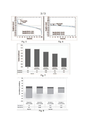
[0031] Figura 7 - gráfico representando os resultados de atrito em função dos valores de Rmr entre o estado da técnica e a presente invenção; e[0031] Figure 7 - graph representing the friction results as a function of the Rmr values between the state of the art and the present invention; and
[0032] Figura 8 - gráfico representando o desgaste do anel e da camisa de cilindro para diversos tipos de revestimentos de carbono amorfo em função dos valores de Rmr.[0032] Figure 8 - graph representing the wear of the ring and cylinder liner for various types of amorphous carbon coatings as a function of Rmr values.
[0033] Descrição Detalhada dos Desenhos[0033] Detailed Description of the Drawings
[0034] A presente invenção refere-se a um elemento deslizante, particularmente um anel 10 de pistão para motores de combustão interna compreendendo um revestimento 15 de carbono amorfo duro do tipo ta-C que apresenta um perfil de rugosidade com valores Rmr (0,30,5) superior a pelo menos 25% e/ou valores Rmr (0,3-0,5) superior a pelo menos 50%.[0034] The present invention relates to a sliding element, particularly a
[0035] Conforme se verá na sequência, o perfil de rugosidade com predominância de platôs 18 quando utilizado em conjunto com um re-vestimento de carbono amorfo tal como o da presente invenção gera um comportamento superior aos elementos deslizantes do estado da técnica.[0035] As will be seen below, the roughness profile with a predominance of
[0036] Em um primeiro momento cumpre referir que o elemento deslizante da presente invenção é preferencialmente um anel 10 de pistão para motores de combustão interna que operem com elevada carga e/ou potência. Usualmente esses anéis 10 de pistão trabalham com folgas muito justas e um filme de óleo fino para garantir excelente rendimento e baixas emissões de CO2.[0036] At first, it should be noted that the sliding element of the present invention is preferably a
[0037] Como principais características, o anel 10 de pistão da presente invenção tem como características principais o baixo atrito em um revestimento 15 baseado em uma estrutura de carbono com alta durabilidade cujo resultado deriva de uma topografia na superfície do revestimento especialmente desenvolvida.[0037] As main features, the
[0038] O anel 10 da presente invenção que compreende uma base metálica dotada de uma face deslizante 11 é preferencialmente de ferro fundido, aço, aço inoxidável contendo de 10% a 17% de cromo ou aço carbono. A face deslizante 11 é aquela virada para a região de contato com uma camisa de cilindro 20 e é sobre a face de desliza- mento 11 que é depositado o revestimento 15. Em uma configuração preferencial, a face deslizante 11 recebe, de dentro para fora, uma camada adesiva 14 e um revestimento 15 de carbono amorfo duro do tipo ta-C (vide figuras 1 e 2).[0038] The
[0039] A camada adesiva 14 tem como objetivo promover a acomodação das tensões entre a estrutura metálica do anel 10 e o revestimento 15 de carbono amorfo cujas tensões internas são muito elevadas, garantindo assim uma excelente adesão entre o revestimento 15 funcional e a base metálica. De modo preferencial, mas não obrigatório, a camada adesiva 14 é formada por uma estrutura colunar policris- talina cúbica de corpo centrado (bcc) de cromo cuja espessura varia entre 0,5 e 1 micrometro. Em uma configuração preferencial alternativa, a camada adesiva pode ser de níquel ou cobalto. De todo o modo, a camada adesiva 14 é depositada por um processo de deposição por vapor a partir de uma fonte metálica.[0039] The
[0040] Por sua vez, a camada antiatrito, representada na figura 2 como revestimento 15 e doravante assim designada, é composta por carbono totalmente amorfo livre ou substancialmente livre de hidrogênio (DLC) com uma quantidade predominante de sp3. No tocante à isenção de hidrogênio, é importante notar que sua quantidade em peso é inferior a 2%.[0040] In turn, the anti-friction layer, represented in Figure 2 as
[0041] No tocante à relação entre sp3 e sp2, cumpre notar que, em uma configuração preferencial, sua relação compreende ligações sp3 superiores a 50%, caracterizando um revestimento 15 de ta-C. Em uma configuração preferencial alternativa, o porcentual de sp3 varia de 55% a 70%. Em outras palavras, a razão da relação entre sp3 e sp2 varia entre 0,42 e 2,33, sendo que, em uma segunda configuração preferencial alternativa, esta razão varia entre 0,70 e 1,50. Nesta configuração preferencial, a elevada quantidade de sp3 no revestimento 15, superior a 50%, tem por objetivo garantir a durabilidade para as condi- ções de trabalho de um motor, uma vez que a quantidade de sp3 é importante no que se refere à estabilidade térmica nos motores de combustão interna, uma vez que elevadas cargas térmicas no motor podem causar a transformação de sp3 (tipo diamante) em sp2 (tipo grafite).[0041] Regarding the relationship between sp3 and sp2, it should be noted that, in a preferred configuration, its ratio comprises sp3 bonds greater than 50%, featuring a
[0042] Ademais, a espessura total do filme da presente invenção varia entre 2 e 25 micrometros, preferencialmente entre 3 e 7 micrometros. Onde uma melhor relação entre tensão interna e espessura do recobrimento é alcançada. No tocante à dureza, o revestimento 15 de carbono amorfo substancialmente isento de hidrogênio compreende uma dureza que se encontra entre 30 e 50 GPa.[0042] In addition, the total thickness of the film of the present invention varies between 2 and 25 micrometers, preferably between 3 and 7 micrometers. Where a better relationship between internal stress and coating thickness is achieved. As far as hardness is concerned, the substantially hydrogen-free
[0043] Cumpre notar ainda que o processo de deposição do revestimento 15 ocorre por um processo de deposição de vapor químico assistido por plasma (PACVD).[0043] It is further noted that the
[0044] De modo distinto das soluções automotivas do estado da técnica, a presente invenção utiliza uma topografia na superfície de contato do revestimento 15 especialmente desenvolvida, capaz de ser adaptada à superfície de contato 21 da camisa 20 de cilindro. O desenvolvimento da presente invenção permitiu entender que em muitas situações de contato tribológicas de deslizamento e abrasão, os revestimentos de elevada rugosidade têm resultados inferiores.[0044] Unlike prior art automotive solutions, the present invention uses a specially developed topography on the contact surface of the
[0045] Deste modo, a presente invenção tem por objeto um anel de pistão 10 dotado de um revestimento 15 compreendendo uma dureza superior a 4000 HV (dureza Vickers), mas que evita alto desgaste da camisa 20 de cilindro cuja dureza é consideravelmente menor, usualmente inferior a 700 HV (dureza Vickers), ou mesmo 250 a 300 HV.[0045] Thus, the present invention has as its object a
[0046] Para alcançar os objetivos da presente invenção, o revestimento 15 do anel 10 de pistão compreende uma superfície controlada da quantidade de vales, com vista a maximizar o fornecimento de óleo durante o funcionamento da partida do motor, aumentando também o filme de óleo e reduzindo os pontos de contato sólido, o que provoca um menor coeficiente de atrito no sistema tribológico (anel de pis- tão/camisa de cilindro).[0046] To achieve the objectives of the present invention, the
[0047] Contribuindo em grande escala para os excelentes resultados da presente invenção, a superfície do revestimento 15 da presente invenção compreende uma topografia cujo contato com a superfície de contato 21 da camisa 20 de cilindro ocorre principalmente por meio de platôs 18.[0047] Contributing on a large scale to the excellent results of the present invention, the surface of the
[0048] A norma ISO4287 define os parâmetros de rugosidade para proporção do material da superfície (Rmr), que reflete a porcentagem de material a uma determinada profundidade medida a partir de uma linha de referência a uma determinada profundidade. Para melhor entendimento, a título de exemplo, uma comparação das figuras 3 e 5 com as figuras 4 e 6, permite perceber que, quando uma determinada topografia compreende muito picos 16 (vide figuras 3 e 5), uma leitura para uma linha de referência a uma distância de 0,2 micrometro gera um valor de Rmr menor e uma leitura para uma linha de referência a uma distância de 0,3 micrometro gera um valor de Rmr superior.[0048] The ISO4287 standard defines the roughness parameters for surface material ratio (Rmr), which reflects the percentage of material at a given depth measured from a reference line at a given depth. For better understanding, by way of example, a comparison of figures 3 and 5 with figures 4 and 6, allows us to see that, when a given topography comprises many peaks 16 (see figures 3 and 5), a reading for a reference line at a distance of 0.2 micron gives a lower Rmr value and a reading for a reference line at a distance of 0.3 micron gives a higher Rmr value.
[0049] Por sua vez, uma topografia compreendendo platôs 18 ao invés de picos 16 gera um valor de Rmr mais elevado (vide figuras 4 e 6), evidenciando que a proporção de material na superfície é maior. Por outras palavras, os gráficos das figuras 5 e 6 revelam a porcentagem de material a uma determinada profundidade medida entre o pico 16 mais alto (0%) e o vale 17 mais profundo (100%). Neste tipo de análises, o porcentual é obtido traçando uma linha horizontal com uma mesma distância e a uma mesma profundidade, verificando-se quanto dessa linha através o material com relação à totalidade do comprimento da linha.[0049] In turn, a
[0050] Deste modo, as figuras 5 e 6 permitem compreender a diferença entre uma superfície com e sem picos, respectivamente. A pre sente invenção faz uso de uma superfície de contato muito similar àquela encontrada na situação da figura 6, i.e., uma superfície formada substancialmente por platôs 18, o que garante uma boa sustentação na região de contato entre o anel 10 de pistão e a camisa 20 de cilindro. Como resultado, quanto mais platôs 18 uma região de contato possuir, menor será o coeficiente de atrito.[0050] Thus, figures 5 and 6 allow to understand the difference between a surface with and without peaks, respectively. The present invention makes use of a contact surface very similar to that found in the situation in figure 6, ie, a surface formed substantially by
[0051] Desta forma, os valores de Rmr são de enorme importância para poder caracterizar os platôs 18 da presente invenção, uma vez que tais valores permitem compreender a topografia específica que permite obter uma solução de baixo atrito, alta durabilidade e desgaste reduzido.[0051] Thus, the Rmr values are of enormous importance to be able to characterize the
[0052] Em anéis do estado da técnica, a presença de picos 16 provoca o riscamento e o desgaste crítico na parede da camisa 20 do cilindro devido à elevada pressão de contato. Ademais, esta elevada pressão local dificulta a formação e a manutenção do filme de óleo lubrificante, mesmo que haja óleo presente nos vales 17 do revestimento de carbono amorfo livre de hidrogênio (DLC).[0052] In prior art rings, the presence of
[0053] A solução da presente invenção pode ser descrita como semelhante àquela encontrada na figura 4. Assim, para se resolver os problemas do estado da técnica, foi desenvolvida uma superfície de platôs 18 com o intuito de garantir uma boa sustentação no contato entre o anel 10 de pistão e a camisa 20 de cilindro. Para uma mesma carga, esta superfície gera uma baixa pressão de contato quando comparada com uma topografia contendo picos 16. Desta forma, o acabamento do anel 10 de pistão é de enorme importância para a realização do contato entre o anel 10 e a camisa 20, de forma a contribuir para uma boa operação do motor. A boa compatibilidade entre o anel 10 de pistão e a camisa de cilindro 20 é obtida por um processo de remoção dos picos 16 do revestimento 15, processo este que ocorre após a deposição do revestimento 15.[0053] The solution of the present invention can be described as similar to that found in figure 4. Thus, to solve the problems of the prior art, a
[0054] Nesse sentido, a presente invenção tem como característica da topografia do revestimento 15 do anel 10 de pistão o fato de o valor de Rmr (0,2/0,5) ser igual ou superior a 25% e o valor de Rmr (0,3/0,5) ser igual ou superior a 50%. De modo preferencial alternativo, o valor de Rmr (0,3/0,5) é igual ou superior a 65%.[0054] In this sense, the present invention has as a characteristic of the topography of the lining 15 of the
[0055] Os resultados laboratoriais obtidos durante o desenvolvimento do elemento deslizante da presente invenção claramente demonstram suas vantagens. Nesse sentido, a figura 7 mostra o desempenho, em termos de atrito e desgaste do anel de pistão em função dos parâmetros de Rmr tanto para anéis do estado da técnica, como para anéis da presente invenção. Cumpre notar que os testes foram realizados com valores de Rmr dentro do relatório, sendo obtidos valores para a presente invenção de Rmr (0,2-0,5) maior ou igual a 25% e Rmr (0,3-0,5) maior ou igual a 50%.[0055] The laboratory results obtained during the development of the sliding element of the present invention clearly demonstrate its advantages. In this sense, Figure 7 shows the performance, in terms of friction and wear of the piston ring as a function of the Rmr parameters both for rings of the prior art and for rings of the present invention. It should be noted that the tests were performed with Rmr values within the report, with values for the present invention being obtained of Rmr (0.2-0.5) greater than or equal to 25% and Rmr (0.3-0.5) greater than or equal to 50%.
[0056] Os resultados da figura 7 mostram que o revestimento de carbono amorfo substancialmente livre de hidrogênio e o revestimento de nitreto de cromo apresentam diferentes níveis de Rmr. O coeficiente de atrito dos revestimentos de carbono apresenta uma redução com o aumento do porcentual de Rmr. Por sua vez, os valores mais à direita na tabela da figura 7 revelam que o revestimento da presente invenção de DLC e o revestimento de CrN apresentam sensivelmente os mesmos valores de Rmr. De todo o modo, o revestimento de DLC da presente invenção apresenta um coeficiente de fricção substancialmente 50% menor que no revestimento de CrN.[0056] The results of Figure 7 show that the substantially hydrogen-free amorphous carbon coating and the chromium nitride coating have different levels of Rmr. The coefficient of friction of carbon coatings decreases with increasing Rmr percentage. In turn, the rightmost values in the table in Figure 7 reveal that the DLC coating of the present invention and the CrN coating have roughly the same Rmr values. In any case, the DLC coating of the present invention has a coefficient of friction substantially 50% lower than that of the CrN coating.
[0057] A figura 8 mostra ainda o desempenho no que se refere ao desgaste de diversos revestimentos de DLC da presente invenção frente a um revestimento de DLC do estado da técnica. Os resultados evidenciam a vantagem da solução da presente invenção, pois revelam que a presença de platôs 18 da presente invenção (valores de Rmr superiores) proporcionam menor desgaste no anel 10 de pistão (colunas acima do zero) e menor degaste na camisa 20 de cilindro (colunas abaixo do zero). Por outras palavras, para revestimentos de carbono amorfo, quando os valores de Rmr alcançam o perfil topográfico da presente invenção, o desgaste tanto do anel 10 de pistão quanto da camisa 20 de cilindro, são bastante inferiores.[0057] Figure 8 also shows the performance with regard to wear of several DLC coatings of the present invention against a prior art DLC coating. The results show the advantage of the solution of the present invention, as they reveal that the presence of
[0058] Assim, não restam dúvidas de que a presente invenção, ao conciliar o uso de revestimentos 15 de carbono amorfo substancialmente livres de hidrogênio com uma topologia que apresenta um perfil de Rmr elevado onde o contato com a camisa de cilindro é mantido principalmente por platôs 18, o coeficiente de atrito é bastante reduzido e o desgaste tanto do anel quanto do cilindro é também reduzido, o que garante o correto comportamento em qualquer estágio de funcionamento do motor e assegura uma vida longa aos motores.[0058] Thus, there is no doubt that the present invention, by reconciling the use of substantially hydrogen-free amorphous carbon coatings with a topology that presents a high Rmr profile where the contact with the cylinder liner is mainly maintained by
[0059] Tendo sido descrito um exemplo de concretização preferido, deve ser entendido que o escopo da presente invenção abrange outras possíveis variações, sendo limitado tão somente pelo teor das reivindicações apensas, aí incluídos os possíveis equivalentes.[0059] Having described an example of preferred embodiment, it should be understood that the scope of the present invention encompasses other possible variations, being limited only by the content of the appended claims, including possible equivalents.
Claims (11)
Priority Applications (4)
| Application Number | Priority Date | Filing Date | Title |
|---|---|---|---|
| BR102015025731-7A BR102015025731B1 (en) | 2015-10-08 | 2015-10-08 | sliding element |
| DE102016217557.2A DE102016217557A1 (en) | 2015-10-08 | 2016-09-14 | Slide |
| CN201610855224.XA CN107013360B (en) | 2015-10-08 | 2016-09-27 | Sliding element |
| US15/289,097 US10400895B2 (en) | 2015-10-08 | 2016-10-07 | Sliding element |
Applications Claiming Priority (1)
| Application Number | Priority Date | Filing Date | Title |
|---|---|---|---|
| BR102015025731-7A BR102015025731B1 (en) | 2015-10-08 | 2015-10-08 | sliding element |
Publications (2)
| Publication Number | Publication Date |
|---|---|
| BR102015025731A2 BR102015025731A2 (en) | 2017-05-02 |
| BR102015025731B1 true BR102015025731B1 (en) | 2021-05-18 |
Family
ID=58405588
Family Applications (1)
| Application Number | Title | Priority Date | Filing Date |
|---|---|---|---|
| BR102015025731-7A BR102015025731B1 (en) | 2015-10-08 | 2015-10-08 | sliding element |
Country Status (4)
| Country | Link |
|---|---|
| US (1) | US10400895B2 (en) |
| CN (1) | CN107013360B (en) |
| BR (1) | BR102015025731B1 (en) |
| DE (1) | DE102016217557A1 (en) |
Families Citing this family (11)
| Publication number | Priority date | Publication date | Assignee | Title |
|---|---|---|---|---|
| US10323747B2 (en) | 2017-03-28 | 2019-06-18 | Mahle International Gmbh | Piston ring and method for manufacturing a piston ring |
| DE102017210559A1 (en) * | 2017-06-22 | 2018-12-27 | Mahle International Gmbh | Piston ring for a piston of an internal combustion engine |
| DE102017221606A1 (en) * | 2017-11-30 | 2019-06-06 | Federal-Mogul Burscheid Gmbh | piston ring |
| US20190368607A1 (en) * | 2018-05-29 | 2019-12-05 | Mahle International Gmbh | Piston ring and method for manufacturing a piston ring |
| JP6533631B1 (en) * | 2019-01-16 | 2019-06-19 | 株式会社加地テック | Gas compressor and method of manufacturing gas compressor |
| US11276797B2 (en) * | 2019-04-15 | 2022-03-15 | Advanced Semiconductor Engineering, Inc. | Optical device and method of manufacturing the same |
| JP6962998B2 (en) * | 2019-12-17 | 2021-11-05 | 株式会社リケン | Combination of cylinder and piston ring |
| DE102020202259A1 (en) | 2020-02-21 | 2021-08-26 | Federal-Mogul Burscheid Gmbh | Sliding element, in particular piston ring, and method for producing the same |
| DE102020124180A1 (en) * | 2020-09-16 | 2022-03-17 | Federal-Mogul Burscheid Gmbh | Sliding element, in particular a piston ring |
| US20240376983A1 (en) | 2023-05-08 | 2024-11-14 | Mahle International Gmbh | Coating for a piston ring |
| DE102024113983A1 (en) * | 2024-05-17 | 2025-11-20 | MTU Aero Engines AG | Sliding bearing arrangement and aircraft engine with a sliding bearing arrangement |
Family Cites Families (9)
| Publication number | Priority date | Publication date | Assignee | Title |
|---|---|---|---|---|
| US6066399A (en) | 1997-03-19 | 2000-05-23 | Sanyo Electric Co., Ltd. | Hard carbon thin film and method of forming the same |
| JP2004137535A (en) * | 2002-10-16 | 2004-05-13 | Nissan Motor Co Ltd | Hard carbon coating sliding member |
| DE102009003232A1 (en) * | 2009-05-19 | 2010-12-02 | Federal-Mogul Burscheid Gmbh | Sliding element of an internal combustion engine, in particular piston ring |
| CN102002684B (en) * | 2009-08-31 | 2014-07-30 | 日立金属株式会社 | Slide part |
| DE112011100377B4 (en) | 2010-01-29 | 2022-12-15 | Nippon Piston Ring Co., Ltd. | piston ring |
| JP5376668B2 (en) * | 2010-02-26 | 2013-12-25 | 日本ピストンリング株式会社 | piston ring |
| DE102011003254A1 (en) | 2011-01-27 | 2012-08-02 | Federal-Mogul Burscheid Gmbh | Sliding element, in particular piston ring, with a coating and method for producing a sliding element |
| DE102011076410A1 (en) * | 2011-05-24 | 2012-11-29 | Schaeffler Technologies AG & Co. KG | machine element |
| DE102012020757A1 (en) | 2012-10-23 | 2014-05-08 | Mahle International Gmbh | Component with a coating and process for its preparation |
-
2015
- 2015-10-08 BR BR102015025731-7A patent/BR102015025731B1/en active IP Right Grant
-
2016
- 2016-09-14 DE DE102016217557.2A patent/DE102016217557A1/en active Pending
- 2016-09-27 CN CN201610855224.XA patent/CN107013360B/en active Active
- 2016-10-07 US US15/289,097 patent/US10400895B2/en active Active
Also Published As
| Publication number | Publication date |
|---|---|
| US20170102071A1 (en) | 2017-04-13 |
| CN107013360A (en) | 2017-08-04 |
| US10400895B2 (en) | 2019-09-03 |
| DE102016217557A1 (en) | 2017-04-13 |
| CN107013360B (en) | 2020-10-16 |
| BR102015025731A2 (en) | 2017-05-02 |
Similar Documents
| Publication | Publication Date | Title |
|---|---|---|
| BR102015025731B1 (en) | sliding element | |
| JP5452734B2 (en) | Process for manufacturing slide elements with a coating, in particular piston rings, and slide elements | |
| BR112015009584B1 (en) | SLIDING ELEMENT, IN PARTICULAR A PISTON RING, HAVING A COATING | |
| BR102015032127B1 (en) | SLIDING ELEMENT | |
| BR112012022007B1 (en) | PISTON RING, AND A METHOD FOR COATING A PISTON RING | |
| CN101208461B (en) | Piston ring having hard multi-layer coating | |
| RU2649490C2 (en) | Sliding element, in particular, a piston ring having a coating | |
| BR112013013370B1 (en) | sliding element, in particular, piston ring with a coating | |
| BR112012010336B1 (en) | sliding element and combination of a sliding element | |
| BRPI0509345B1 (en) | process for producing a coating on a piston ring as well as a piston ring | |
| BR112015002898B1 (en) | SLIDING ELEMENT, PARTICULARLY PISTON RING, HAVING RESISTANT COATING | |
| BR112016016403B1 (en) | SLIDING ELEMENT, PARTICULARLY PISTON RING | |
| BRPI1100176A2 (en) | engine component | |
| BR102014025243B1 (en) | PISTON RING FOR INTERNAL COMBUSTION ENGINES, PROCESS FOR OBTAINING PISTON RING AND INTERNAL COMBUSTION ENGINE | |
| BR102013012133A2 (en) | Piston ring | |
| BR102016017735B1 (en) | sliding element for internal combustion engines | |
| BR102013031072A2 (en) | slip set | |
| BRPI0920854B1 (en) | METHOD FOR FINISHING A PISTON RING OR CYLINDER SHIRT, AND A PISTON RING OR CYLINDER SHIRT OF AN INTERNAL COMBUSTION ENGINE | |
| BR102016015392A2 (en) | SLIDING ELEMENT FOR INTERNAL COMBUSTION ENGINES | |
| BR112012022008B1 (en) | A composite helical spring for a ring of a piston of an internal combustion engine, and a method for coating a helical compression spring | |
| BRPI1102336B1 (en) | element provided with at least one sliding surface for use in a combustion engine | |
| Kong et al. | Engineering research of DLC coating in piston pins and bucket tappets | |
| US10344242B2 (en) | Mechanical part coated with a layer of amorphous carbon for sliding in relation to a less hard component | |
| BR102016007169B1 (en) | PISTON RING FOR INTERNAL COMBUSTION ENGINES, PROCESS FOR OBTAINING PISTON RING AND INTERNAL COMBUSTION ENGINE | |
| BR112014026392B1 (en) | INTERNAL COMBUSTION ENGINE JACKET |
Legal Events
| Date | Code | Title | Description |
|---|---|---|---|
| B03A | Publication of a patent application or of a certificate of addition of invention [chapter 3.1 patent gazette] | ||
| B06F | Objections, documents and/or translations needed after an examination request according [chapter 6.6 patent gazette] | ||
| B06U | Preliminary requirement: requests with searches performed by other patent offices: procedure suspended [chapter 6.21 patent gazette] | ||
| B09A | Decision: intention to grant [chapter 9.1 patent gazette] | ||
| B16A | Patent or certificate of addition of invention granted [chapter 16.1 patent gazette] |
Free format text: PRAZO DE VALIDADE: 20 (VINTE) ANOS CONTADOS A PARTIR DE 08/10/2015, OBSERVADAS AS CONDICOES LEGAIS. |