WO2023089695A1 - Steering control device and steering control method - Google Patents
Steering control device and steering control method Download PDFInfo
- Publication number
- WO2023089695A1 WO2023089695A1 PCT/JP2021/042242 JP2021042242W WO2023089695A1 WO 2023089695 A1 WO2023089695 A1 WO 2023089695A1 JP 2021042242 W JP2021042242 W JP 2021042242W WO 2023089695 A1 WO2023089695 A1 WO 2023089695A1
- Authority
- WO
- WIPO (PCT)
- Prior art keywords
- steering
- value
- upper limit
- control device
- target
- Prior art date
- Legal status (The legal status is an assumption and is not a legal conclusion. Google has not performed a legal analysis and makes no representation as to the accuracy of the status listed.)
- Ceased
Links
Images


Classifications
-
- B—PERFORMING OPERATIONS; TRANSPORTING
- B62—LAND VEHICLES FOR TRAVELLING OTHERWISE THAN ON RAILS
- B62D—MOTOR VEHICLES; TRAILERS
- B62D6/00—Arrangements for automatically controlling steering depending on driving conditions sensed and responded to, e.g. control circuits
- B62D6/002—Arrangements for automatically controlling steering depending on driving conditions sensed and responded to, e.g. control circuits computing target steering angles for front or rear wheels
-
- B—PERFORMING OPERATIONS; TRANSPORTING
- B62—LAND VEHICLES FOR TRAVELLING OTHERWISE THAN ON RAILS
- B62D—MOTOR VEHICLES; TRAILERS
- B62D6/00—Arrangements for automatically controlling steering depending on driving conditions sensed and responded to, e.g. control circuits
- B62D6/007—Arrangements for automatically controlling steering depending on driving conditions sensed and responded to, e.g. control circuits adjustable by the driver, e.g. sport mode
-
- B—PERFORMING OPERATIONS; TRANSPORTING
- B62—LAND VEHICLES FOR TRAVELLING OTHERWISE THAN ON RAILS
- B62D—MOTOR VEHICLES; TRAILERS
- B62D1/00—Steering controls, i.e. means for initiating a change of direction of the vehicle
- B62D1/02—Steering controls, i.e. means for initiating a change of direction of the vehicle vehicle-mounted
- B62D1/12—Hand levers
-
- B—PERFORMING OPERATIONS; TRANSPORTING
- B62—LAND VEHICLES FOR TRAVELLING OTHERWISE THAN ON RAILS
- B62D—MOTOR VEHICLES; TRAILERS
- B62D5/00—Power-assisted or power-driven steering
- B62D5/04—Power-assisted or power-driven steering electrical, e.g. using an electric servo-motor connected to, or forming part of, the steering gear
- B62D5/0421—Electric motor acting on or near steering gear
-
- B—PERFORMING OPERATIONS; TRANSPORTING
- B62—LAND VEHICLES FOR TRAVELLING OTHERWISE THAN ON RAILS
- B62D—MOTOR VEHICLES; TRAILERS
- B62D5/00—Power-assisted or power-driven steering
- B62D5/04—Power-assisted or power-driven steering electrical, e.g. using an electric servo-motor connected to, or forming part of, the steering gear
- B62D5/0457—Power-assisted or power-driven steering electrical, e.g. using an electric servo-motor connected to, or forming part of, the steering gear characterised by control features of the drive means as such
- B62D5/046—Controlling the motor
Definitions
- the present disclosure relates to a steering control device and a steering control method.
- a steer-by-wire steering system in which the power transmission path between the operation unit to which the steering wheel is connected and the steering unit that steers the steered wheels is separated.
- a steering control device that controls such a steering device changes the angle ratio of the steering angle of the steered wheels to the steering angle of the steering wheel in accordance with the driving conditions of the vehicle.
- Patent Document 2 discloses that a joystick is used in addition to or instead of the steering wheel as an operation member operated by the driver.
- the joystick is the operating member, it is possible to reduce the amount of operation required to steer the steered wheels compared to the case where the steering wheel is the operating member, thereby improving convenience for the driver. can.
- the joystick is the operating member as described above
- the amount of change in the turning angle with respect to the amount of change in the amount of operation increases. That is, even if the amount of operation of the joystick is small, the steered angle of the steered wheels changes greatly. Therefore, it is difficult to finely adjust the steering angle of the steered wheels.
- the steering control device that controls a steering device of a vehicle.
- the steering device has a structure in which power transmission paths are separated between an operation unit having an operation lever and a steering unit configured to steer steerable wheels.
- the steering control device includes a target steering correspondence value calculation unit configured to calculate a target steering correspondence value, which is a target value of a convertible value that can be converted into a steering angle of the steered wheels; a control signal generator configured to generate a control signal for actuating the steering unit based on the rudder correspondence value.
- the target steering correspondence value calculation unit performs low sensitivity determination processing for determining whether or not a low sensitivity condition for reducing the amount of change in the steering angle with respect to the amount of change in the amount of operation of the operation lever is satisfied; normal arithmetic processing for calculating the target steering corresponding value based on the operation amount when the sensitivity condition is not satisfied; and normal arithmetic processing based on the operation amount when the low sensitivity condition is satisfied. and low-sensitivity calculation processing for calculating the target steering correspondence value having a smaller absolute value than the target steering correspondence value calculated by.
- the steering control method includes calculating a target steering correspondence value that is a target value of a convertible value that can be converted into a steering angle of the steered wheels; and calculating the target steering corresponding value, wherein the low sensitivity condition for reducing the amount of change in the steering angle with respect to the amount of change in the amount of operation of the operating lever is a low sensitivity determination process for determining whether or not the low sensitivity condition is satisfied; a normal calculation process for calculating the target steering corresponding value based on the operation amount when the low sensitivity condition is not satisfied; and low-sensitivity calculation processing for calculating the target steering correspondence value having a smaller absolute value than the target steering correspondence value calculated by the normal calculation processing, based on the operation amount if true.
- FIG. 1 is a schematic configuration diagram of a steering system of one embodiment and a steering control system that controls the steering system;
- FIG. 2 is a block diagram of the steering control device of FIG. 1;
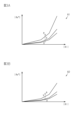
- FIG. 3A is a diagram showing an example of a normal map possessed by the steering control device of FIG. 1, and
- FIG. 3B is a diagram showing an example of a low sensitivity map possessed by the steering control device of FIG. 2 is a flowchart showing an example of a processing procedure of target steering corresponding angle calculation by a target steering corresponding angle calculation unit of the steering control device of FIG. 1;
- FIG. 2 is a flow chart showing an example of a procedure of guard processing by a guard processing section of the steering control device of FIG. 1;
- FIG. FIG. 2 is a flow chart showing an example of a processing procedure for calculating an upper limit speed by a guard processing section of the steering control device of FIG. 1;
- a steering control device 1 controls a steer-by-wire steering device 2 .
- the steering device 2 changes the traveling direction of the vehicle by steering the steerable wheels 3 according to the operation of the driver.
- the steering device 2 includes an operation unit 4 operated by the driver and a steering unit 5 for steering the steered wheels 3 .
- the steering device 2 has a structure in which the power transmission path between the operation unit 4 and the steering unit 5 is mechanically separated.
- the operation unit 4 includes an operation lever 11 that is operated by the driver, and a base 12 that supports the operation lever 11 so that it can tilt.
- the base 12 of this embodiment supports the operation lever 11 so as to be tiltable in the lateral direction of the vehicle, that is, in the left-right direction. That is, the amount of operation by the driver is represented by the tilt angle of the operating lever 11 (hereinafter referred to as lever tilt angle ⁇ l).
- the base 12 may support the operation lever 11 so as to be tiltable in the longitudinal direction of the vehicle.
- the operation unit 4 includes a tilt angle sensor 13 that detects the lever tilt angle ⁇ l.
- the lever tilt angle ⁇ l is detected as a positive value when the operation lever 11 is tilted to the right and as a negative value when the operation lever 11 is tilted to the left.
- the steering unit 5 includes a pinion shaft 21, a rack shaft 22 connected to the pinion shaft 21, a rack housing 23 reciprocatingly housing the rack shaft 22, and a rack and pinion having the pinion shaft 21 and the rack shaft 22. a mechanism 24;
- the rack and pinion mechanism 24 is configured by meshing pinion teeth 21 a formed on the pinion shaft 21 and rack teeth 22 a formed on the rack shaft 22 .
- Tie rods 26 are connected to both ends of the rack shaft 22 via ball joints 25 .
- the tip of the tie rod 26 is connected to a knuckle (not shown) to which the steered wheels 3 are assembled.
- the steering unit 5 also includes a steering actuator 31 that imparts a steering force, which is a force for steering the steered wheels 3, to the rack shaft 22.
- the steering actuator 31 includes a steering motor 32 and a power transmission mechanism 33 that transmits the torque of the steering motor 32 to the rack shaft 22 .
- the power transmission mechanism 33 has a belt mechanism 34 and a ball screw mechanism 35 .
- the steering actuator 31 transmits the rotation of the steering motor 32 to the ball screw mechanism 35 via the belt mechanism 34 , and converts the rotation to the reciprocating motion of the rack shaft 22 by the ball screw mechanism 35 , thereby steering the steered wheels 3 . give power.
- a steering force is applied from the steering actuator 31 according to the operation of the operation lever 11 by the driver.
- the rack shaft 22 reciprocates, and the steering angle ⁇ i of the steerable wheels 3 is changed.
- the steering actuator 31 steers the steered wheels 3 according to the driver's operation.
- the steering control device 1 is connected to the steering motor 32 and controls the operation of the steering motor 32 .
- the steering control device 1 is also connected to an alarm device 37 and controls the operation of the alarm device 37 .
- the annunciator 37 may be a device such as a display panel or a speaker that outputs a physical quantity that the driver can recognize with his/her five senses.
- Detection results of various sensors are input to the steering control device 1 .
- Various sensors include the tilt angle sensor 13, the vehicle speed sensor 41, the rotation angle sensor 42, and the acceleration sensor 43, for example.
- a vehicle speed sensor 41 detects a vehicle speed V, which is the running speed of the vehicle.
- the rotation angle sensor 42 detects the rotation angle ⁇ t of the rotation shaft of the steering motor 32 as a relative angle within the range of 360°.
- the acceleration sensor 43 of this embodiment detects the lateral acceleration GY and the vertical acceleration GZ of the vehicle.
- the vertical acceleration GZ is detected as a positive value for upward acceleration and a negative value for downward acceleration, but the reverse is also possible.
- the acceleration sensor may detect longitudinal acceleration of the vehicle in addition to lateral acceleration GY and vertical acceleration GZ.
- a lateral acceleration sensor that detects lateral acceleration GY and a vertical acceleration sensor that detects vertical acceleration GZ may be individually connected to steering control device 1 .
- the switch signal Ss of the sensitivity switch 14 is input to the steering control device 1 . Further, the steering control device 1 receives a position signal Sp from a position sensor 44 that detects the shift position of a shift lever (not shown).
- the shift positions include, for example, a parking position P for parking the vehicle, a reverse position R for reversing the vehicle, and a drive position D for advancing the vehicle. Then, the steering control device 1 controls the operation of the steering motor 32 based on the input state variables.
- the steering control device 1 includes a microcomputer 51 that outputs a control signal Mt, and a drive circuit 52 that supplies power to the steering motor 32 based on the control signal Mt.
- the microcomputer 51 which is a processing circuit, includes (1) one or more processors that operate according to a computer program (software), (2) an application specific integrated circuit (ASIC) that executes at least part of various processes, and the like. or (3) a combination thereof.
- the processor includes a CPU and memory, such as RAM and ROM, which stores program code or instructions configured to cause the CPU to perform processes.
- Memory or non-transitory computer-readable media includes any available media that can be accessed by a general purpose or special purpose computer.
- Various controls by the microcomputer 51 are executed by the CPU executing programs stored in the memory at predetermined calculation cycles.
- a typical PWM inverter having a plurality of switching elements such as FETs and IGBTs is employed in the drive circuit 52 .
- the control signal Mt is a gate on/off signal that defines the on/off state of each switching element.
- the steering control device 1 controls the motor torque generated by the steering motor 32 by supplying electric power to the steering motor 32 to steer the steered wheels 3 .
- the microcomputer 51 outputs a control signal Mt as each of the following control blocks executes arithmetic processing for each predetermined arithmetic cycle.
- the microcomputer 51 receives the vehicle speed V, the lever inclination angle .theta.l, the rotation angle .theta.t, the lateral acceleration GY, the vertical acceleration GZ, the switch signal Ss, and the position signal Sp.
- the microcomputer 51 generates and outputs a control signal Mt based on these state variables.
- the microcomputer 51 includes a steering corresponding angle calculator 61 that calculates the steering corresponding angle ⁇ p, and a target steering corresponding angle ⁇ p that calculates a target steering corresponding angle ⁇ p*, which is a target value of the steering corresponding angle ⁇ p. It has a computing section 62 and a control signal generating section 63 that generates a control signal Mt.
- the rotation angle ⁇ t of the steering motor 32 is input to the steering corresponding angle calculator 61 .
- the steering corresponding angle calculation unit 61 counts, for example, the number of rotations of the steering motor 32 from the midpoint, and calculates the integrated angle by integrating the rotation angle ⁇ t with the midpoint being zero degrees. Then, the steered corresponding angle calculator 61 multiplies this integrated angle by a conversion factor based on the reduction ratio of the belt mechanism 34, the lead of the ball screw mechanism 35, and the rotational speed ratio of the rack and pinion mechanism 24. Then, the steering corresponding angle ⁇ p is calculated.
- the turning corresponding angle ⁇ p corresponds to the pinion angle, which is the rotation angle of the pinion shaft 21, and the midpoint is the rotation angle of the pinion shaft 21 when the vehicle travels straight. Since the pinion shaft 21 rotates according to the reciprocating motion of the rack shaft 22 as described above, the rotation angle of the pinion shaft 21, that is, the steered corresponding angle ⁇ p can be converted into the steered angle ⁇ i of the steered wheels 3. It corresponds to the steering corresponding value which is the actual value of the value, and the steering corresponding angle calculation section 61 corresponds to the steering corresponding value calculation section.
- the steering corresponding angle ⁇ p calculated by the steering corresponding angle calculator 61 is output to the control signal generator 63 .
- the vehicle speed V, the lever inclination angle ⁇ l, the lateral acceleration GY, the vertical acceleration GZ, the switch signal Ss, and the position signal Sp are input to the target steering corresponding angle calculator 62 .
- the target steering corresponding angle calculation unit 62 calculates a target steering corresponding angle ⁇ p*, which is a target value of the steering corresponding angle ⁇ p, based on these state variables. That is, the target steering response angle ⁇ p* corresponds to a target steering response value that is a target value of a convertible value that can be converted into the steering angle ⁇ i of the steered wheels 3. It corresponds to a steering corresponding value calculation section. Calculation processing of the target steering corresponding angle ⁇ p* by the target steering corresponding angle calculator 62 will be described later.
- the target steering corresponding angle ⁇ p* is output to the control signal generator 63 .
- the vehicle speed V, the lever inclination angle ⁇ l, the steering corresponding angle ⁇ p, the target steering corresponding angle ⁇ p*, and a mode signal Sm, which will be described later, are input to the control signal generation unit 63 .
- the control signal generator 63 generates the control signal Mt based on these state variables.
- control signal generator 63 includes a subtractor 71 , a guard processor 72 and a feedback controller 73 .
- the wording of a feedback may be described as "F/B.”
- the steering corresponding angle ⁇ p and the target steering corresponding angle ⁇ p* are input to the subtractor 71 .
- a subtractor 71 calculates a difference ⁇ p by subtracting the turning corresponding angle ⁇ p from the target turning corresponding angle ⁇ p*.
- the difference ⁇ p is output to the guard processing section 72 .
- the guard processing unit 72 receives the vehicle speed V, the lever inclination angle ⁇ l, and the mode signal Sm. Based on these state variables, the guard processing unit 72 calculates a difference ⁇ pg by limiting the difference ⁇ p to a difference upper limit value ⁇ lim or less.
- the difference upper limit value ⁇ lim is a value that is set according to the upper limit of the steering speed of the steered wheels 3 . Guard processing of the difference ⁇ p by the guard processing unit 72 will be described later.
- the difference ⁇ pg after guard processing is output to the F/B control section 73 .
- the difference ⁇ pg used for F/B calculation is limited to the difference upper limit value ⁇ lim or less according to the upper limit speed. Therefore, when electric power is supplied from the drive circuit 52 to the steering motor 32 in accordance with the control signal Mt, the steered wheels 3 are rotated at a steering speed equal to or lower than the upper limit speed and the steering angle ⁇ i corresponding to the target steering correspondence angle ⁇ p*. is steered so that That is, the control signal generator 63 generates the control signal Mt so that the steering speed of the steered wheels 3 is equal to or lower than the upper limit speed.
- the target steering corresponding angle calculation unit 62 executes low sensitivity determination processing for determining whether or not the low sensitivity condition is satisfied, and prohibition determination processing for determining whether or not the prohibition condition is satisfied.
- the low sensitivity condition is used to determine whether or not the vehicle should reduce the amount of change in the steering angle ⁇ i with respect to the amount of change in the lever inclination angle ⁇ l, that is, whether or not the angle ratio ⁇ should be reduced.
- the prohibition condition is a condition for judging whether or not the vehicle should be prohibited from reducing the amount of change in the steering angle ⁇ i with respect to the lever inclination angle ⁇ l, that is, whether the vehicle should be prohibited from decreasing the angle ratio ⁇ . is.
- the target steering corresponding angle calculation unit 62 When the low sensitivity condition is not satisfied or the prohibition condition is satisfied, the target steering corresponding angle calculation unit 62 performs normal calculation processing for calculating the target steering corresponding angle ⁇ p* based on the lever inclination angle ⁇ l and the vehicle speed V. to run. On the other hand, when the low sensitivity condition is satisfied and the prohibition condition is not satisfied, the target steering corresponding angle calculation unit 62 calculates the target steering corresponding angle ⁇ p calculated by normal arithmetic processing based on the lever inclination angle ⁇ l and the vehicle speed V. A low-sensitivity calculation process for calculating a target steering corresponding angle ⁇ p* having an absolute value smaller than * is executed.
- the target steering corresponding angle calculation unit 62 does not perform the low sensitivity calculation process and performs the normal calculation process even when the low sensitivity condition is satisfied. Calculate the steering corresponding angle ⁇ p*.
- the state in which the target steering response angle calculation unit 62 calculates the target steering response angle ⁇ p* by normal operation processing will be referred to as the normal mode, and the target steering response angle ⁇ p* will be calculated by the low-sensitivity operation processing. This state is sometimes referred to as low sensitivity mode.
- the target steering corresponding angle calculator 62 includes a memory 62a.
- the memory 62a stores a normal map 81 as normal calculation information and a low sensitivity map 82 as low sensitivity calculation information.
- the normal map 81 and the low sensitivity map 82 show the relationship between the lever inclination angle ⁇ l, the vehicle speed V, and the target steering corresponding angle ⁇ p*. That is, the normal map 81 and the low sensitivity map 82 are three-dimensional maps showing the relationship between the lever inclination angle ⁇ l and the vehicle speed V and the target steering corresponding angle ⁇ p*. In the illustrated example, in both the normal map 81 and the low sensitivity map 82, the target steering corresponding angle ⁇ p* is zero degrees when the lever inclination angle ⁇ l is zero degrees.
- Both the normal map 81 and the low sensitivity map 82 are set such that the absolute value of the target steering corresponding angle ⁇ p* increases as the absolute value of the lever inclination angle ⁇ l increases. Both the normal map 81 and the low sensitivity map 82 are set such that the absolute value of the target steering corresponding angle ⁇ p* increases as the vehicle speed V decreases.
- the amount of change in the absolute value of the target steering correspondence angle ⁇ p* with respect to the amount of change in the lever tilt angle ⁇ l and the vehicle speed V in the low sensitivity map 82 is the target steering correspondence with respect to the amount of change in the lever tilt angle ⁇ l and the vehicle speed V in the normal map 81. It is set to be smaller than the amount of change in the absolute value of the angle ⁇ p*.
- the absolute value of the target steering response angle ⁇ p* in the low sensitivity map 82 can be set to an arbitrary lever inclination angle ⁇ l and vehicle speed V, except when the absolute value of the target steering response angle ⁇ p* in the normal map 81 is zero. , which is smaller than the absolute value of the target steering corresponding angle ⁇ p* in the normal map 81 .
- the target steering corresponding angle calculation unit 62 calculates the target steering corresponding angle ⁇ p* according to the lever inclination angle ⁇ l and the vehicle speed V by referring to the normal map 81 in the normal calculation process.
- the target steering corresponding angle calculation section 62 calculates a target steering corresponding angle ⁇ p* corresponding to the lever inclination angle ⁇ l and the vehicle speed V by referring to the low sensitivity map 82 in the low sensitivity calculation process. That is, the target steering corresponding angle calculation unit 62 switches the map used between the normal calculation process and the low-sensitivity calculation process.
- the target steering corresponding angle calculator 62 calculates a target steering corresponding angle ⁇ p* having a smaller absolute value than the target steering corresponding angle ⁇ p* calculated in the normal calculation process.
- the target steering corresponding angle calculation unit 62 When the prohibition condition is not satisfied and the low sensitivity condition is satisfied, the target steering corresponding angle calculation unit 62 outputs a mode signal Sm indicating the low sensitivity mode to the guard processing unit 72 and the annunciator 37 . That is, the target steering corresponding angle calculation unit 62 executes the notification process.
- This mode signal Sm is configured to cause the annunciator 37 to perform an informing operation to the effect that the target steering corresponding angle calculator 62 is in the low sensitivity mode.
- the target steering corresponding angle calculation unit 62 when the prohibition condition is satisfied or when the low sensitivity condition is not satisfied, the target steering corresponding angle calculation unit 62 outputs a mode signal Sm indicating the normal mode to the guard processing unit 72 and the annunciator 37.
- This mode signal Sm is configured to cause the annunciator 37 to perform an informing operation to the effect that the target steering corresponding angle calculator 62 is in the normal mode. That is, the target steering corresponding angle calculator 62 corresponds to a
- the target steering corresponding angle calculator 62 determines that the low sensitivity condition is satisfied when at least one of the following conditions is satisfied.
- the vehicle speed V is equal to or greater than the high speed determination threshold value Vth, and the absolute value of the lever inclination angle ⁇ l is equal to or less than the straight travel determination threshold value ⁇ lth.
- the vehicle speed V is equal to or greater than the high speed determination threshold value Vth, and the absolute value of the lateral acceleration GY is equal to or less than the turning determination threshold value GYth.
- the vehicle speed V is equal to or greater than the high speed determination threshold value Vth, and the vertical acceleration GZ is equal to or less than the tilt determination threshold value GZth.
- the sensitivity switch 14 is on.
- the shift position of the shift lever is the reverse position R;
- the high speed determination threshold value Vth is the vehicle speed V at which it can be determined that the vehicle is traveling at high speed, and is set in advance.
- the straight travel determination threshold value ⁇ lth is a lever tilt angle ⁇ l at which it can be determined that the operating lever 11 is not tilted, and is set in advance.
- the turning determination threshold value GYth is a lateral acceleration GY at which it can be determined that the vehicle is not making a large turn, and is set in advance.
- the inclination determination threshold value GZth is a vertical acceleration GZ at which it can be determined that the vehicle is traveling on a cant road, and is set to a negative value in advance.
- the low-sensitivity conditions include conditions based on the results of magnitude comparisons with thresholds of running parameters that indicate the running state of the vehicle.
- vehicle speed V, lateral acceleration GY, and vertical acceleration GZ are running parameters.
- the low sensitivity condition includes a condition based on the ON/OFF state of the sensitivity switch 14.
- FIG. As in (a5), the low sensitivity condition includes the condition that the vehicle is in reverse.
- the target steering corresponding angle calculator 62 determines that the prohibition condition is satisfied when the following condition is satisfied. (b1) The operating speed ⁇ l of the operating lever 11 is greater than or equal to the sudden operation determination threshold ⁇ lth.
- the sudden operation determination threshold ⁇ lth is an operation speed ⁇ l at which it can be determined that the driver is suddenly operating the operation lever 11, and is set in advance.
- the target steering corresponding angle calculator 62 of the present embodiment calculates the operation speed ⁇ l by differentiating the lever inclination angle ⁇ l.
- a speed sensor may be provided in the operation unit 4 and the operation speed ⁇ l may be input from the speed sensor.
- the target steering corresponding angle calculator 62 obtains various state variables (step 101) and calculates the operating speed ⁇ l of the operating lever 11 (step 102). Subsequently, the target steering corresponding angle calculator 62 determines whether or not the operation speed ⁇ l is equal to or greater than the sudden operation determination threshold value ⁇ lth (step 103). If the operation speed ⁇ l is greater than or equal to the sudden operation determination threshold value ⁇ lth (step 103: YES), the normal map 81 is used to calculate the target steering corresponding angle ⁇ p* (step 104).
- step 105 a mode signal Sm indicating the normal mode is output (step 105), and the process ends.
- the processing of step 103 corresponds to prohibition determination processing
- the processing of step 104 corresponds to normal calculation processing
- the processing of step 105 corresponds to notification processing.
- the target steering corresponding angle calculator 62 determines whether or not the sensitivity switch 14 is on (step 106). . If the sensitivity switch 14 is on (step 106: YES), the low sensitivity map 82 is used to calculate the target steering corresponding angle ⁇ p* (step 107). Then, a mode signal Sm indicating the low sensitivity mode is output (step 108), and the process ends.
- the processing of step 107 corresponds to the low sensitivity calculation processing, and the processing of step 108 corresponds to the notification processing.
- the target steering corresponding angle calculator 62 determines whether or not the position signal Sp indicates the reverse position R (step 109). If the position signal Sp is the reverse position R (step 109: YES), the process proceeds to steps 107 and 108 and the corresponding processing is performed.
- the target steering corresponding angle calculator 62 determines whether the vehicle speed V is equal to or higher than the high speed determination threshold Vth (step 110). If the vehicle speed V is equal to or higher than the high speed determination threshold value Vth (step 110: YES), it is determined whether or not the absolute value of the lever inclination angle ⁇ l is equal to or less than the straight travel determination threshold value ⁇ lth (step 111). If the absolute value of the lever inclination angle ⁇ l is greater than the straight running determination threshold value ⁇ lth (step 111: NO), it is determined whether or not the absolute value of the lateral acceleration GY is equal to or less than the turning determination threshold value GYth (step 112).
- step 112 If the absolute value of the lateral acceleration GY is greater than the turn determination threshold value GYth (step 112: NO), it is determined whether or not the vertical acceleration GZ is equal to or less than the negative tilt determination threshold value GZth (step 113). If the vertical acceleration GZ is greater than the negative tilt determination threshold value GZth (step 113: NO), the process proceeds to steps 104 and 105 to perform corresponding processing. Also, if the vehicle speed V is less than the high speed determination threshold value Vth (step 110: NO), the process similarly proceeds to steps 104 and 105 to perform corresponding processing.
- step 111: YES When the absolute value of the lever inclination angle ⁇ l is equal to or less than the straight travel determination threshold value ⁇ lth (step 111: YES), the target steering corresponding angle calculation unit 62 proceeds to steps 107 and 108 and performs corresponding processing. If the absolute value of the lateral acceleration GY is equal to or less than the turn determination threshold value GYth (step 112: YES), or if the vertical acceleration GZ is equal to or less than the negative inclination determination threshold value GZth (step 113: YES), step 107 is performed in the same manner. , 108 to perform the corresponding processing. The processing of steps 109 to 113 corresponds to the low sensitivity determination processing.
- guard processing unit 72 executes upper limit speed calculation processing for setting the upper limit speed of the steered wheels 3 .
- the guard processing unit 72 executes difference upper limit value calculation processing for calculating the difference upper limit value ⁇ lim according to the upper limit speed, and guard processing for limiting the difference ⁇ p based on the magnitude comparison between the difference ⁇ p and the difference upper limit value ⁇ lim. do.
- the guard processing unit 72 of this embodiment calculates the upper limit speed according to the running state of the vehicle and the operating state of the control lever 11 . More specifically, even if the lever inclination angle ⁇ l remains constant, the target steering corresponding angle ⁇ p* may change due to a change in the mode of the target steering corresponding angle calculator 62 . Based on this situation, the guard processing unit 72 has a transition upper limit speed that is the upper limit speed when transitioning from the normal mode to the low sensitivity mode, and a return upper limit speed that is the upper limit speed when returning to the normal mode from the low sensitivity mode. are calculated individually based on the vehicle speed V. That is, the transition upper limit speed and the return upper limit speed are set individually. Based on the mode signal Sm, the guard processing unit 72 determines whether the mode has been switched from the normal mode to the low-sensitivity mode or from the low-sensitivity mode to the normal mode.
- the guard processing unit 72 Based on the vehicle speed V, the guard processing unit 72 separately calculates the upper limit speed for turning, which is the upper limit speed when performing the turning operation, and the upper limit speed for turning back, which is the upper limit speed when performing the turning operation. In other words, the upper limit speed for cutting and the upper limit speed for switching back are set individually.
- the turning operation is an operation to increase the absolute value of the lever inclination angle ⁇ l
- the return operation is an operation to decrease the absolute value of the lever inclination angle ⁇ l.
- the guard processing unit 72 of the present embodiment determines whether a turning operation is being performed or a steering back operation is being performed based on the amount of change in the absolute value of the lever inclination angle ⁇ l. In another embodiment, the guard processing unit 72 may determine whether the turning operation is being performed or the steering back operation is being performed based on the amount of change in the absolute value of the steering corresponding angle ⁇ p.
- the guard processing unit 72 calculates a general-purpose upper limit speed, which is the upper limit speed in cases other than the above.
- a general-purpose upper limit speed which is the upper limit speed in cases other than the above.
- the guard processing unit 72 determines that the normal mode has switched to the low-sensitivity mode, it calculates the transition upper limit speed based on the vehicle speed V.
- FIG. The guard processing unit 72 of the present embodiment performs calculations so that the higher the vehicle speed V, the lower the transition upper limit speed. Alternatively, the higher the vehicle speed V, the higher the transition upper limit speed.
- the guard processing unit 72 has a map or a functional expression indicating the relationship between the vehicle speed V and the transition upper limit speed, and calculates the transition upper limit speed according to the vehicle speed V by referring to the map or the functional expression.
- the guard processing unit 72 determines that a turning operation is being performed, it calculates a turning upper limit speed based on the vehicle speed V.
- the guard processing unit 72 of this embodiment performs calculations such that the higher the vehicle speed V, the lower the upper limit cutting speed. Alternatively, the higher the vehicle speed V, the higher the upper limit cutting speed.
- the guard processing unit 72 calculates the cutting upper limit speed using a map or a functional expression.
- the guard processing unit 72 determines that the switchback operation is being performed, it calculates the upper limit speed for switchback based on the vehicle speed V.
- the guard processing unit 72 of the present embodiment performs calculations so that the higher the vehicle speed V, the lower the upper limit speed of steering return. Further, when the vehicle speed V is the same, the guard processing unit 72 may set the upper limit speed for reversal to a value larger or smaller than the upper limit speed for turning.
- the guard processing unit 72 calculates the upper limit speed for switching back in the same manner as when calculating the upper limit speed for transition.
- the guard processing unit 72 calculates the general upper limit speed based on the vehicle speed V.
- the guard processing unit 72 of the present embodiment sets the general-purpose upper limit speed lower as the vehicle speed V increases, but may set the general-purpose upper limit speed higher as the vehicle speed V increases.
- the guard processing unit 72 calculates the general-purpose upper limit speed in the same manner as when calculating the transition upper limit speed.
- the guard processing unit 72 calculates the difference upper limit value ⁇ lim corresponding to the calculated upper limit speed, that is, the transition upper limit speed, the return upper limit speed, the cutting upper limit speed, the reversing upper limit speed, or the general-purpose upper limit speed. do.
- the guard processing unit 72 has a map or a functional expression indicating the relationship between the upper limit speed and the upper limit difference value ⁇ lim, and refers to the map or the functional expression to calculate the upper limit difference value ⁇ lim according to the calculated upper limit speed. .
- the guard processing unit 72 compares the absolute value of the input difference ⁇ p and the calculated difference upper limit value ⁇ lim. When the absolute value of the difference ⁇ p is equal to or less than the difference upper limit value ⁇ lim, the guard processing unit 72 outputs the input difference ⁇ p as it is to the F/B control unit 73 as the difference ⁇ pg after guard processing. On the other hand, if the absolute value of the difference ⁇ p is greater than the difference upper limit value ⁇ lim, the guard processing unit 72 maintains the sign of the input difference ⁇ p and makes the absolute value equal to the difference upper limit value ⁇ lim after guard processing. is output to the F/B control section 73 as the difference ⁇ pg.
- the guard processing unit 72 of the present embodiment performs guard processing using the difference upper limit value ⁇ lim corresponding to the transition upper limit speed when the normal mode changes to the low sensitivity mode while the turning operation or the switching back operation is being performed. I do. However, in another embodiment, in such a case, guard processing may be performed using the difference upper limit value ⁇ lim corresponding to the upper limit speed for cutting or the upper limit speed for steering back. Further, the guard processing unit 72 of the present embodiment uses the difference upper limit value ⁇ lim corresponding to the upper limit return speed when the low sensitivity mode is changed to the normal mode while the cutting operation or the switchback operation is being performed. Perform guard processing. However, in another embodiment, in such a case, guard processing may be performed using the difference upper limit value ⁇ lim corresponding to the upper limit speed for cutting or the upper limit speed for steering back.
- FIG. 5 when the guard processing unit 72 acquires various state variables (step 201), it calculates the upper limit speed (step 202). Calculation of the upper limit speed is performed according to the flowchart shown in FIG.
- the processing of step 202 corresponds to the upper limit speed calculation processing.
- the guard processing unit 72 determines whether or not the normal mode has changed to the low sensitivity mode based on the mode signal Sm (step 301). If the mode changes from the normal mode to the low sensitivity mode (step 301: YES), the transition upper limit speed is calculated based on the vehicle speed V (step 302).
- the guard processing unit 72 determines whether or not the switching back operation has been performed (step 307). If the steering back operation is being performed (step 307: YES), the steering back upper limit speed is calculated based on the vehicle speed V (step 308). On the other hand, if the steering-back operation has not been performed (step 307: NO), the general-purpose upper limit speed is calculated based on the vehicle speed V (step 309).
- the guard processing unit 72 calculates a difference upper limit value ⁇ lim corresponding to the calculated upper limit speed (step 203).
- the processing of step 203 corresponds to the difference upper limit value calculation processing.
- step 204 it is determined whether or not the absolute value of the difference ⁇ p acquired in step 201 is equal to or less than the difference upper limit value ⁇ lim (step 204). If the absolute value of the difference .DELTA..theta.p is equal to or less than the difference upper limit .DELTA..theta.lim (step 204: YES), the difference .DELTA..theta.p is directly output as the difference .DELTA..theta.pg after guard processing (step 205), and the process is terminated.
- step 204 if the absolute value of the difference ⁇ p is greater than the difference upper limit value ⁇ lim (step 204: NO), the sign of the acquired difference ⁇ p is maintained while the absolute value is equal to the difference upper limit value ⁇ lim after the guard processing. It is output as the difference ⁇ pg (step 206), and the process ends.
- the processing of steps 205 and 206 corresponds to guard processing.
- the target steering corresponding angle calculation unit 62 calculates a target steering corresponding angle ⁇ p* smaller in absolute value than the target steering corresponding angle ⁇ p* calculated by normal calculation processing based on the lever inclination angle ⁇ l.
- a low-sensitivity calculation process is executed to calculate the steering corresponding angle ⁇ p*. Therefore, when the low sensitivity condition is satisfied, the target steering corresponding angle ⁇ p* is calculated to be smaller than usual.
- the angle ratio ⁇ becomes smaller, so that the operation of finely adjusting the steering angle ⁇ i of the steerable wheels 3 becomes easier.
- the steering device 2 has a sensitivity switch 14 operated by the driver.
- the target steering corresponding angle calculator 62 determines whether or not the low sensitivity condition is satisfied based on the ON/OFF state of the sensitivity switch 14 . Therefore, the angle ratio ⁇ can be reduced according to the intention of the driver.
- the target steering corresponding angle calculation unit 62 further executes prohibition determination processing for determining whether or not the prohibition condition is satisfied. , the low-sensitivity arithmetic processing is not executed, and the normal arithmetic processing is executed. Therefore, when the prohibition condition is satisfied, the angle ratio ⁇ does not decrease and the steerable wheels 3 can be steered greatly. As a result, the steerable wheels 3 can be steered smoothly, for example, when avoiding an obstacle in front of the vehicle.
- the target steering corresponding angle calculation unit 62 determines whether or not the prohibition condition is satisfied based on whether or not the operation speed ⁇ l of the operation lever 11 is equal to or greater than the sudden operation determination threshold value ⁇ lth. In many cases, quick maneuvers are performed when avoiding obstacles. Therefore, for example, when avoiding an obstacle, decreasing the angle ratio ⁇ can be appropriately prohibited.
- the target steering corresponding angle calculator 62 includes a memory 62a.
- the memory 62a stores a normal map 81 and a low sensitivity map 82 showing the relationship between the lever inclination angle ⁇ l and the target steering corresponding angle ⁇ p*.
- the amount of change in the absolute value of the target turning correspondence angle ⁇ p* with respect to the amount of change in the lever inclination angle ⁇ l and the vehicle speed V in the low sensitivity map 82 is set to be smaller than that in the normal map 81 .
- the normal calculation process is a process of calculating the target steering corresponding angle ⁇ p* based on the lever inclination angle ⁇ l using the normal map 81 .
- the low-sensitivity calculation process is a process of calculating the target steering corresponding angle ⁇ p* based on the lever inclination angle ⁇ l using the low-sensitivity map 82 . That is, the target steering corresponding angle calculation unit 62 switches the map used between the normal calculation process and the low-sensitivity calculation process. As a result, the target steering corresponding angle calculation section 62 can easily calculate the target steering corresponding angle ⁇ p* having a smaller absolute value than the target steering corresponding angle ⁇ p* calculated by the normal calculation process in the low sensitivity mode. be able to.
- the control signal generator 63 generates a control signal Mt for controlling the steering speed of the steered wheels 3 to be equal to or lower than the upper limit speed.
- the control signal generation unit 63 has a subtractor 71 that calculates the difference between the turning corresponding angle ⁇ p and the target turning corresponding angle ⁇ p*, and the absolute value of the difference and a F/B control unit 73 for generating a control signal Mt based on the difference after guard processing.
- the absolute value of the difference ⁇ p may be limited to the difference upper limit value ⁇ lim or less, so that the turning speed of the steerable wheels 3 is set to the upper limit speed or less compared to the case where the speed F/B control is executed, for example. It is possible to reduce the computational load for
- the guard processing unit 72 executes upper limit speed calculation processing for calculating the upper limit speed based on the vehicle speed V.
- the degree to which the behavior of the vehicle is disturbed differs according to the vehicle speed V.
- an appropriate upper limit speed can be set according to the vehicle speed V.
- the guard processing unit 72 individually sets the transition upper limit speed and the return upper limit speed. Therefore, it is possible to steer the steerable wheels 3 at an appropriate steering speed, which is caused by the switching of the target steered corresponding angle calculator 62 to the normal mode or the low sensitivity mode.
- the guard processing unit 72 individually sets the upper limit speed for cutting and the upper limit speed for turning back. Therefore, the steered wheels 3 can be steered at an appropriate steering speed depending on whether the turning operation or the turning-back operation is performed.
- This embodiment can be implemented with the following modifications.
- This embodiment and the following modified examples can be implemented in combination with each other within a technically consistent range.
- the guard processing unit 72 individually calculates the upper limit speed for cutting and the upper limit speed for reversing, it does not distinguish between the cutting operation and the reversing operation. may be calculated.
- the guard processing unit 72 sets the transition upper limit speed and the return upper limit speed individually, a single upper limit speed may be calculated as the upper limit speed at the time of mode change.
- only the general-purpose upper limit speed may be calculated as the upper limit speed.
- At least one of the transition upper limit speed, return upper speed limit, turning upper limit speed, steering return upper limit speed, and general purpose upper limit speed is not set as a value calculated based on the vehicle speed V by the guard processing unit 72, but as a preset fixed value. good too.
- the control signal generation unit 63 limits the absolute value of the difference ⁇ p to the difference upper limit value ⁇ lim or less, thereby generating the control signal Mt that makes the turning speed of the steered wheels 3 equal to or less than the upper limit speed.
- the present invention is not limited to this, and the control signal Mt may be generated by executing speed feedback control so that the turning speed of the steered wheels 3 is equal to or lower than the upper limit speed. Further, the control signal generator 63 may generate the control signal Mt without considering the turning speed of the steered wheels 3 .
- the microcomputer 51 does not have to include the steering corresponding angle calculator 61 .
- the turning corresponding angle ⁇ p which is the rotation angle of the pinion shaft 21, may be input from a sensor that detects the rotation angle of the pinion shaft 21, for example.
- the sensor may detect the rotation angle of the pinion shaft 21 as an absolute angle exceeding the range of 360°.
- the target steering corresponding angle calculation unit 62 switches the map used in the normal calculation process and the low sensitivity calculation process, so that when the low sensitivity condition is satisfied, the target steering correspondence angle calculated by the normal calculation process A target steering corresponding angle ⁇ p* having an absolute value smaller than ⁇ p* was calculated.
- the normal map 81 is used in the normal calculation process to calculate the target steering corresponding angle ⁇ p*
- the low sensitivity calculation process uses the normal map 81 to calculate the target steering corresponding angle ⁇ p*. By correcting , a target steering response angle ⁇ p* having a smaller absolute value than the target steering response angle ⁇ p* may be calculated.
- a predetermined value may be subtracted from the target steering corresponding angle ⁇ p* calculated using the normal map 81, or the target steering corresponding angle ⁇ p* calculated using the normal map 81 may be changed to " A gain smaller than 1" may be multiplied.
- the target steering corresponding angle calculator 62 includes a single low-sensitivity map 82, but may include two or more low-sensitivity maps. For example, when a first low-sensitivity map and a second low-sensitivity map are provided, the second low-sensitivity map is set so that the absolute value of the target steering corresponding angle ⁇ p* with respect to the lever inclination angle ⁇ l is smaller than that of the first low-sensitivity map. may be For example, when only one of (a1) to (a5) is satisfied, the target steering corresponding angle calculation unit 62 calculates the target steering corresponding angle ⁇ p* using the first low sensitivity map, and ( If any two or more of a1) to (a5) are satisfied, the second low-sensitivity map may be used to calculate the target steering corresponding angle ⁇ p*.
- a dead zone may be set in the normal map 81 and the low sensitivity map 82 .
- a range may be set near the zero degree of the lever inclination angle ⁇ l in which the target steering corresponding angle ⁇ p* remains zero degrees even if the absolute value of the lever inclination angle ⁇ l increases.
- the normal map 81 and the low sensitivity map 82 may be two-dimensional maps showing the relationship between the lever inclination angle ⁇ l and the target steering corresponding angle ⁇ p*. That is, the normal calculation process and the low-sensitivity calculation process may be processes for calculating the target steering corresponding angle ⁇ p* based only on the lever inclination angle ⁇ l.
- the normal calculation information and the low-sensitivity calculation information may be, for example, functional expressions instead of maps.
- the target steering corresponding angle calculation unit 62 has determined the conditions (a1) to (a5) in order to determine whether the low sensitivity condition is satisfied, it is also possible to determine only at least one of these conditions. Also, other conditions may be used to determine whether or not the low sensitivity condition is met.
- Conditions (a1) to (a5) can be changed as appropriate.
- the condition (a2) in addition to determining whether the absolute value of the lateral acceleration GY is equal to or less than the turning determination threshold value GYth, it is determined whether the absolute value of the yaw rate of the vehicle is equal to or less than the turning determination threshold value GYth. you can go Further, the high-speed determination threshold values Vth of (a1) to (a3) may be different values.
- the target steering corresponding angle calculation section 62 determines the condition (b1) in order to determine whether the prohibition condition is satisfied.
- Such another condition may be, for example, the input of a signal indicating that the driver has performed a sudden braking operation. Further, the target steering corresponding angle calculation unit 62 does not have to determine whether the prohibition condition is met.
- the processing procedure by the target steering corresponding angle calculation unit 62 is not limited to the procedure shown in FIG. 4, and can be changed as appropriate.
- the normal map 81 is immediately used to calculate the target steering corresponding angle ⁇ p* (step 104).
- the corresponding angle ⁇ p* may be changed to a value based on the low sensitivity map 82 .
- the processing procedure by the guard processing unit 72 is not limited to the procedures shown in FIGS. 5 and 6, and can be changed as appropriate.
- the convertible value that can be converted into the turning angle ⁇ i of the steered wheels 3 is the rotation angle of the pinion shaft 21, but is not limited to this, for example, the stroke amount of the rack shaft 22 or the turning angle. ⁇ i itself may be a convertible value.
- the sensitivity switch 14 may be a switch of the type that switches to the ON state only while the driver is pressing it. Also, the sensitivity switch 14 may be a dial-type multistage switch capable of switching between three or more states. Such a multistage switch is preferably used when the target steering corresponding angle calculator 62 has a plurality of low-sensitivity maps. Furthermore, the steering device 2 may not have the sensitivity switch 14 .
- the microcomputer 51 is separately provided with a notification control section for determining the low sensitivity condition and the prohibition condition in the same manner as the target steering corresponding angle calculation section 62, and this notification control section notifies the low sensitivity mode through the notification device 37. You may Also, the microcomputer 51 does not have to report that it is in the low sensitivity mode.
- the operation lever 11 is tiltably supported on the base 12 , it is not limited to this, and may be supported slidably on the base 12 , for example.
- the amount of operation by the driver is represented by the amount of slide of the operation lever 11 .
- the operating lever 11 may be used to control the driving/braking of the vehicle in addition to controlling the steering angle ⁇ i of the steered wheels 3 .
- the operation unit 4 may include a motor and/or a spring that imparts a reaction force to the operation lever 11 to the operation by the driver.
- the lever inclination angle ⁇ l may be detected based on the rotation angle of the motor.
- the operating unit 4 may comprise, in addition to the operating lever 11, a steering wheel operated by the driver.
- the steering device 2 has a linkless structure in which the power transmission between the operation unit 4 and the steering unit 5 is separated. A structure capable of separating power transmission between the operation unit 4 and the steering unit 5 may be employed.
- the steering actuator 31 transmits the rotation of the steering motor 32 to the ball screw mechanism 35 via the belt mechanism 34, but is not limited to this.
- the steering actuator 31 may be configured to transmit to 35 .
- the steering actuator 31 may be configured such that the steering motor 32 directly rotates the ball screw mechanism 35 .
- the steering unit 5 is configured to include a second rack-and-pinion mechanism, and the rotation of the steering motor 32 is converted into reciprocating motion of the rack shaft 22 by the second rack-and-pinion mechanism.
- the steering actuator 31 may be configured to apply a steering force to the .
- the low-sensitivity condition may include a straight running condition including that the vehicle speed, which is the running parameter, is equal to or higher than the high speed determination threshold, and that the absolute value of the operation amount is equal to or less than the straight running determination operation amount. .
- the low-sensitivity condition is that the vehicle speed, which is the running parameter, is equal to or higher than the high speed determination threshold; It may include turning conditions including
- the vertical acceleration of the vehicle is detected as a positive value for upward acceleration and a negative value for downward acceleration. and that the vertical acceleration, which is the running parameter, is equal to or less than a negative slope determination threshold.
Landscapes
- Engineering & Computer Science (AREA)
- Chemical & Material Sciences (AREA)
- Combustion & Propulsion (AREA)
- Transportation (AREA)
- Mechanical Engineering (AREA)
- Physics & Mathematics (AREA)
- Mathematical Physics (AREA)
- Steering Control In Accordance With Driving Conditions (AREA)
Abstract
Description
本開示は、操舵制御装置及び操舵制御方法に関する。 The present disclosure relates to a steering control device and a steering control method.
従来、ステアリングホイールが連結される操作ユニットと転舵輪を転舵させる転舵ユニットとの間の動力伝達路が分離されたステアバイワイヤ式の操舵装置がある。例えば特許文献1に記載されるように、こうした操舵装置を制御する操舵制御装置は、車両の走行状況に応じて、ステアリングホイールの操舵角に対する転舵輪の転舵角の角度比を変更する。
Conventionally, there is a steer-by-wire steering system in which the power transmission path between the operation unit to which the steering wheel is connected and the steering unit that steers the steered wheels is separated. For example, as described in
特許文献2には、運転者が操作する操作部材として、ステアリングホイールに加えて又は代えて、ジョイスティックを採用したものが開示されている。ジョイスティックが操作部材である場合、ステアリングホイールが操作部材である場合に比べ、転舵輪を転舵させる際に必要な操作量を小さくすることが可能であり、運転者の利便性を向上させることができる。
上記のようにジョイスティックが操作部材である場合において、転舵輪を転舵させる際に必要な操作量を小さくすることで、操作量の変化量に対する転舵角の変化量が大きくなる。すなわち、ジョイスティックの操作量が小さくても、転舵輪の転舵角が大きく変化する。そのため、転舵輪の転舵角を微調整する操作が難しい。 In the case where the joystick is the operating member as described above, by reducing the amount of operation required to steer the steered wheels, the amount of change in the turning angle with respect to the amount of change in the amount of operation increases. That is, even if the amount of operation of the joystick is small, the steered angle of the steered wheels changes greatly. Therefore, it is difficult to finely adjust the steering angle of the steered wheels.
本開示の一態様では、車両の操舵装置を制御する操舵制御装置が提供される。前記操舵装置は、操作レバーを有する操作ユニットと、転舵輪を転舵させるように構成される転舵ユニットとの間の動力伝達路が分離した構造を有する。前記操舵制御装置は、前記転舵輪の転舵角に換算可能な換算可能値の目標値である目標転舵対応値を演算するように構成される目標転舵対応値演算部と、前記目標転舵対応値に基づいて、前記転舵ユニットを作動させる制御信号を生成するように構成される制御信号生成部と、を備える。前記目標転舵対応値演算部は、前記操作レバーの操作量の変化量に対する前記転舵角の変化量を小さくする低感度条件が成立するか否かを判定する低感度判定処理と、前記低感度条件が成立しない場合に、前記操作量に基づいて、前記目標転舵対応値を演算する通常演算処理と、前記低感度条件が成立する場合に、前記操作量に基づいて、前記通常演算処理によって演算される前記目標転舵対応値よりも小さな絶対値を有する前記目標転舵対応値を演算する低感度演算処理と、を実行するように構成される。 One aspect of the present disclosure provides a steering control device that controls a steering device of a vehicle. The steering device has a structure in which power transmission paths are separated between an operation unit having an operation lever and a steering unit configured to steer steerable wheels. The steering control device includes a target steering correspondence value calculation unit configured to calculate a target steering correspondence value, which is a target value of a convertible value that can be converted into a steering angle of the steered wheels; a control signal generator configured to generate a control signal for actuating the steering unit based on the rudder correspondence value. The target steering correspondence value calculation unit performs low sensitivity determination processing for determining whether or not a low sensitivity condition for reducing the amount of change in the steering angle with respect to the amount of change in the amount of operation of the operation lever is satisfied; normal arithmetic processing for calculating the target steering corresponding value based on the operation amount when the sensitivity condition is not satisfied; and normal arithmetic processing based on the operation amount when the low sensitivity condition is satisfied. and low-sensitivity calculation processing for calculating the target steering correspondence value having a smaller absolute value than the target steering correspondence value calculated by.
本開示の別の態様では、車両の操舵装置を制御する操舵制御方法が提供される。前記操舵装置は、操作レバーを有する操作ユニットと、転舵輪を転舵させるように構成される転舵ユニットとの間の動力伝達路が分離した構造を有する。前記操舵制御方法は、前記転舵輪の転舵角に換算可能な換算可能値の目標値である目標転舵対応値を演算することと、前記目標転舵対応値に基づいて、前記転舵ユニットを作動させる制御信号を生成することと、を含み、前記目標転舵対応値を演算することは、前記操作レバーの操作量の変化量に対する前記転舵角の変化量を小さくする低感度条件が成立するか否かを判定する低感度判定処理と、前記低感度条件が成立しない場合に、前記操作量に基づいて、前記目標転舵対応値を演算する通常演算処理と、前記低感度条件が成立する場合に、前記操作量に基づいて、前記通常演算処理によって演算される前記目標転舵対応値よりも小さな絶対値の前記目標転舵対応値を演算する低感度演算処理と、を実行することと、を含む。 Another aspect of the present disclosure provides a steering control method for controlling a steering system of a vehicle. The steering device has a structure in which power transmission paths are separated between an operation unit having an operation lever and a steering unit configured to steer steerable wheels. The steering control method includes calculating a target steering correspondence value that is a target value of a convertible value that can be converted into a steering angle of the steered wheels; and calculating the target steering corresponding value, wherein the low sensitivity condition for reducing the amount of change in the steering angle with respect to the amount of change in the amount of operation of the operating lever is a low sensitivity determination process for determining whether or not the low sensitivity condition is satisfied; a normal calculation process for calculating the target steering corresponding value based on the operation amount when the low sensitivity condition is not satisfied; and low-sensitivity calculation processing for calculating the target steering correspondence value having a smaller absolute value than the target steering correspondence value calculated by the normal calculation processing, based on the operation amount if true. including
以下、操舵制御装置の一実施形態を図面に従って説明する。
(全体構成)
図1に示すように、操舵制御装置1は、ステアバイワイヤ式の操舵装置2を制御する。操舵装置2は、運転者の操作に応じて、転舵輪3を転舵させることにより車両の進行方向を変更する。操舵装置2は、運転者により操作される操作ユニット4と、転舵輪3を転舵させる転舵ユニット5とを備えている。操舵装置2は、操作ユニット4と、転舵ユニット5との間の動力伝達路が機械的に分離した構造を有している。
An embodiment of a steering control device will be described below with reference to the drawings.
(overall structure)
As shown in FIG. 1 , a
操作ユニット4は、運転者により操作される操作レバー11と、操作レバー11を傾動可能に支持するベース12とを備えている。本実施形態のベース12は、操作レバー11を車両の横方向、すなわち左右方向に傾動可能に支持しており、操作レバー11は、運転者の操作により左右方向に傾動する。つまり、運転者の操作量は、操作レバー11の傾斜角(以下、レバー傾角θlという)によって表される。他の実施形態では、ベース12は、操作レバー11を車両の前後方向に傾動可能に支持してもよい。
The
図示の例では、操作ユニット4は、レバー傾角θlを検出する傾斜角センサ13を備えている。レバー傾角θlは、操作レバー11の右方向の傾動を正の値、操作レバー11の左方向の傾動を負の値として検出されるが、逆であってもよい。
In the illustrated example, the
さらに、操作ユニット4は、運転者により操作される感度スイッチ14を備えている。感度スイッチ14は、後述するように、運転者の意思によって操作レバー11のレバー傾角θlに対する転舵輪3の転舵角θiの角度比αを変更するために用いられる。角度比αは、転舵角θiをレバー傾角θlで除算することにより得られる値である(α=θi/θl)。感度スイッチ14からは、感度スイッチ14のオンオフ状態を示すスイッチ信号Ssが操舵制御装置1に出力される。本実施形態の感度スイッチ14は、運転者が一回押圧することにより、オンオフ状態が継続的に切り替わるタイプのスイッチである。感度スイッチ14は、例えば操作レバー11上に配置されるが、これに限らず、ベース12又は運転席近傍等、運転者が操作可能な任意の位置に配置してもよい。
Furthermore, the
転舵ユニット5は、ピニオン軸21と、ピニオン軸21に連結されたラック軸22と、ラック軸22を往復動可能に収容するラックハウジング23と、ピニオン軸21及びラック軸22を有するラックアンドピニオン機構24とを備えている。ラックアンドピニオン機構24は、ピニオン軸21に形成されたピニオン歯21aとラック軸22に形成されたラック歯22aとが噛合されることで構成されている。これにより、ピニオン軸21は、ラック軸22の往復動に応じて回転する。ラック軸22の両端には、ボールジョイント25を介してタイロッド26が連結されている。タイロッド26の先端は、転舵輪3が組み付けられた図示しないナックルに連結されている。
The
また、転舵ユニット5は、ラック軸22に転舵輪3を転舵させる力である転舵力を付与する転舵アクチュエータ31を備えている。図示の例では、転舵アクチュエータ31は、転舵モータ32と、転舵モータ32のトルクをラック軸22に伝達する動力伝達機構33とを備えている。動力伝達機構33は、ベルト機構34と、ボール螺子機構35とを備えている。転舵アクチュエータ31は、転舵モータ32の回転をベルト機構34を介してボール螺子機構35に伝達し、ボール螺子機構35にてラック軸22の往復動に変換することで転舵輪3に転舵力を付与する。
The
このように構成された操舵装置2では、運転者による操作レバー11の操作に応じて転舵アクチュエータ31から転舵力が付与される。これにより、ラック軸22が往復動し、転舵輪3の転舵角θiが変更される。つまり、転舵アクチュエータ31は、運転者の操作に応じて転舵輪3を転舵させる。
In the
操舵制御装置1は、転舵モータ32に接続されており、転舵モータ32の作動を制御する。また、操舵制御装置1は、報知器37に接続されており、報知器37の作動を制御する。報知器37は、ディスプレイパネル又はスピーカ等、運転者が五感で認識できる物理量を出力する機器であればよい。
The
操舵制御装置1には、各種のセンサの検出結果が入力される。各種のセンサには、例えば上記傾斜角センサ13、車速センサ41、回転角センサ42及び加速度センサ43が含まれる。車速センサ41は、車両の走行速度である車速Vを検出する。回転角センサ42は、転舵モータ32の回転軸の回転角θtを360°の範囲内の相対角で検出する。本実施形態の加速度センサ43は、車両の横加速度GY及び上下加速度GZを検出する。上下加速度GZは、上方向の加速を正の値、下方向の加速を負の値として検出されるが、逆であってもよい。他の実施形態では、加速度センサは、横加速度GY及び上下加速度GZに加え、車両の前後加速度を検出してもよい。また、別の実施形態では、横加速度GYを検出する横加速度センサ、及び上下加速度GZを検出する上下加速度センサが個別に操舵制御装置1に接続されてもよい。
Detection results of various sensors are input to the
操舵制御装置1には、上記感度スイッチ14のスイッチ信号Ssが入力される。さらに、操舵制御装置1には、図示しないシフトレバーのシフトポジションを検出するポジションセンサ44からポジション信号Spが入力される。シフトポジションは、例えば車両を駐車するときのパーキングポジションP、車両を後退させるときのリバースポジションR、車両を前進させるときのドライブポジションDを含む。そして、操舵制御装置1は、入力される状態変数に基づいて、転舵モータ32の作動を制御する。
The switch signal Ss of the
(操舵制御装置1)
以下、操舵制御装置1の構成について詳細に説明する。
図2に示すように、操舵制御装置1は、制御信号Mtを出力するマイクロコンピュータ51と、制御信号Mtに基づいて転舵モータ32に電力を供給する駆動回路52とを備えている。
(Steering control device 1)
The configuration of the
As shown in FIG. 2, the
処理回路であるマイクロコンピュータ51は、(1)コンピュータプログラム(ソフトウェア)に従って動作する1つ以上のプロセッサ、(2)各種処理のうち少なくとも一部の処理を実行する特定用途向け集積回路(ASIC)等の1つ以上の専用のハードウェア回路、あるいは(3)それらの組み合わせによって構成することができる。プロセッサは、CPU並びに、RAMおよびROM等のメモリを含み、メモリは、処理をCPUに実行させるように構成されたプログラムコードまたは指令を格納している。メモリすなわち非一時的なコンピュータ可読媒体は、汎用または専用のコンピュータでアクセスできるあらゆる利用可能な媒体を含む。マイクロコンピュータ51による各種制御は、メモリに記憶されたプログラムをCPUが所定の演算周期ごとで実行することによって実行される。
The
駆動回路52には、例えばFETやIGBT等の複数のスイッチング素子を有する典型的なPWMインバータが採用されている。制御信号Mtは、各スイッチング素子のオンオフ状態を規定するゲートオンオフ信号である。
A typical PWM inverter having a plurality of switching elements such as FETs and IGBTs is employed in the
マイクロコンピュータ51から駆動回路52に制御信号Mtが出力されることにより、車載電源から制御信号Mtに応じた電力が転舵モータ32に供給される。これにより、転舵モータ32が回転し、上記のように転舵輪3に転舵力が付与される。このように操舵制御装置1は、転舵モータ32への電力供給を通じて、転舵モータ32が発生するモータトルクを制御し、転舵輪3を転舵させる。
By outputting the control signal Mt from the
(マイクロコンピュータ51)
以下、マイクロコンピュータ51の構成について詳細に説明する。
マイクロコンピュータ51は、所定の演算周期毎に以下の各制御ブロックが演算処理を実行することで、制御信号Mtを出力する。マイクロコンピュータ51には、上記車速V、レバー傾角θl、回転角θt、横加速度GY、上下加速度GZ、スイッチ信号Ss及びポジション信号Spが入力される。マイクロコンピュータ51は、これらの状態変数に基づいて制御信号Mtを生成して出力する。
(Microcomputer 51)
The configuration of the
The
詳しくは、マイクロコンピュータ51は、転舵対応角θpを演算する転舵対応角演算部61と、転舵対応角θpの目標値である目標転舵対応角θp*を演算する目標転舵対応角演算部62と、制御信号Mtを生成する制御信号生成部63とを備えている。
Specifically, the
転舵対応角演算部61には、転舵モータ32の回転角θtが入力される。転舵対応角演算部61は、例えば中点からの転舵モータ32の回転数をカウントし、中点をゼロ度として回転角θtを積算することにより積算角を演算する。そして、転舵対応角演算部61は、この積算角に対して、ベルト機構34の減速比、ボール螺子機構35のリード、及びラックアンドピニオン機構24の回転速度比に基づく換算係数を乗算することにより、転舵対応角θpを演算する。つまり、転舵対応角θpは、ピニオン軸21の回転角であるピニオン角に相当し、中点は、車両が直進する際のピニオン軸21の回転角である。上記のようにピニオン軸21はラック軸22の往復動に応じて回転することから、ピニオン軸21の回転角、すなわち転舵対応角θpは転舵輪3の転舵角θiに換算可能な換算可能値の実際値である転舵対応値に相当し、転舵対応角演算部61は転舵対応値演算部に相当する。転舵対応角演算部61により演算された転舵対応角θpは、制御信号生成部63に出力される。
The rotation angle θt of the
目標転舵対応角演算部62には、車速V、レバー傾角θl、横加速度GY、上下加速度GZ、スイッチ信号Ss及びポジション信号Spが入力される。目標転舵対応角演算部62は、これらの状態変数に基づいて、転舵対応角θpの目標値である目標転舵対応角θp*を演算する。つまり、目標転舵対応角θp*は、転舵輪3の転舵角θiに換算可能な換算可能値の目標値である目標転舵対応値に相当し、目標転舵対応角演算部62は目標転舵対応値演算部に相当する。目標転舵対応角演算部62による目標転舵対応角θp*の演算処理については後述する。目標転舵対応角θp*は、制御信号生成部63に出力される。
The vehicle speed V, the lever inclination angle θl, the lateral acceleration GY, the vertical acceleration GZ, the switch signal Ss, and the position signal Sp are input to the target steering corresponding
制御信号生成部63には、車速V、レバー傾角θl、転舵対応角θp、目標転舵対応角θp*、及び後述するモード信号Smが入力される。制御信号生成部63は、これらの状態変数に基づいて、制御信号Mtを生成する。
The vehicle speed V, the lever inclination angle θl, the steering corresponding angle θp, the target steering corresponding angle θp*, and a mode signal Sm, which will be described later, are input to the control
詳しくは、制御信号生成部63は、減算器71と、ガード処理部72と、フィードバック制御部73とを備えている。なお、以下では、フィードバックという文言を「F/B」と記すことがある。
Specifically, the
減算器71には、転舵対応角θp及び目標転舵対応角θp*が入力される。減算器71は、目標転舵対応角θp*から転舵対応角θpを減算することにより、差分Δθpを演算する。差分Δθpは、ガード処理部72に出力される。
The steering corresponding angle θp and the target steering corresponding angle θp* are input to the
ガード処理部72には、差分Δθpに加え、車速V、レバー傾角θl及びモード信号Smが入力される。ガード処理部72は、これらの状態変数に基づいて、差分Δθpを差分上限値Δθlim以下に制限した差分Δθpgを演算する。差分上限値Δθlimは、転舵輪3の転舵速度の上限速度に応じて設定される値である。ガード処理部72による差分Δθpのガード処理については後述する。ガード処理後の差分Δθpgは、F/B制御部73に出力される。
In addition to the difference Δθp, the
F/B制御部73には、ガード処理後の差分Δθpgが入力される。F/B制御部73は、差分Δθpgに基づいてF/B演算を実行することにより、目標転舵トルクを演算する。一例として、F/B演算には、PID制御演算が採用されるが、これに限らず、PI制御演算等であってもよい。そして、F/B制御部73は、任意の周知技術を用いて、当該目標転舵トルクを転舵モータ32で発生させるような制御信号Mtを生成する。
The difference Δθpg after guard processing is input to the F/
上記のようにF/B演算に用いる差分Δθpgは上限速度に応じた差分上限値Δθlim以下に制限されている。そのため、制御信号Mtに応じて駆動回路52から転舵モータ32に電力が供給されると、上限速度以下の転舵速度で転舵輪3が目標転舵対応角θp*に応じた転舵角θiとなるように転舵される。つまり、制御信号生成部63は、転舵輪3の転舵速度を上限速度以下とするように制御信号Mtを生成する。
As described above, the difference Δθpg used for F/B calculation is limited to the difference upper limit value Δθlim or less according to the upper limit speed. Therefore, when electric power is supplied from the
(目標転舵対応角演算部62)
次に、目標転舵対応角演算部62による目標転舵対応角θp*の演算処理について詳細に説明する。
(Target steering corresponding angle calculator 62)
Next, the calculation processing of the target steering corresponding angle θp* by the target steering corresponding
目標転舵対応角演算部62は、低感度条件が成立するか否かを判定する低感度判定処理、及び禁止条件が成立するか否かを判定する禁止判定処理を実行する。後述するように、低感度条件は、車両がレバー傾角θlの変化量に対する転舵角θiの変化量を小さくすべき状況、すなわち角度比αを小さくすべき状況であるか否かを判定するための条件である。禁止条件は、車両がレバー傾角θlに対する転舵角θiの変化量を小さくすることを禁止すべき状況、すなわち角度比αを小さくすること禁止すべき状況であるか否かを判定するための条件である。
The target steering corresponding
目標転舵対応角演算部62は、低感度条件が成立しない場合又は禁止条件が成立する場合には、レバー傾角θl及び車速Vに基づいて、目標転舵対応角θp*を演算する通常演算処理を実行する。一方、目標転舵対応角演算部62は、低感度条件が成立しかつ禁止条件が成立しない場合に、レバー傾角θl及び車速Vに基づいて、通常演算処理によって演算される目標転舵対応角θp*よりも小さな絶対値の目標転舵対応角θp*を演算する低感度演算処理を実行する。つまり、目標転舵対応角演算部62は、禁止条件が成立する場合には、低感度条件が成立する場合にも、低感度演算処理を実行せず、通常演算処理を実行することで、目標転舵対応角θp*を演算する。なお、以下では、目標転舵対応角演算部62が通常演算処理により目標転舵対応角θp*を演算する状態を通常モードとして参照し、低感度演算処理により目標転舵対応角θp*を演算する状態を低感度モードとして参照することがある。
When the low sensitivity condition is not satisfied or the prohibition condition is satisfied, the target steering corresponding
詳しくは、目標転舵対応角演算部62は、メモリ62aを備えている。メモリ62aは、通常演算情報である通常マップ81及び低感度演算情報である低感度マップ82を記憶している。
Specifically, the target steering corresponding
図3A及び図3Bに示すように、通常マップ81及び低感度マップ82は、レバー傾角θlと車速Vと目標転舵対応角θp*との関係を示す。つまり、通常マップ81及び低感度マップ82は、レバー傾角θl及び車速Vに対する目標転舵対応角θp*の関係を示す3次元マップである。図示の例では、通常マップ81及び低感度マップ82のいずれも、レバー傾角θlがゼロ度である場合、目標転舵対応角θp*がゼロ度である。そして、通常マップ81及び低感度マップ82のいずれも、レバー傾角θlの絶対値が大きくなるほど、目標転舵対応角θp*の絶対値が大きくなるように設定されている。また、通常マップ81及び低感度マップ82のいずれも、車速Vが小さくなるほど、目標転舵対応角θp*の絶対値は大きくなるように設定されている。そして、低感度マップ82におけるレバー傾角θl及び車速Vの変化量に対する目標転舵対応角θp*の絶対値の変化量は、通常マップ81におけるレバー傾角θl及び車速Vの変化量に対する目標転舵対応角θp*の絶対値の変化量よりも小さくなるように設定されている。これにより、低感度マップ82における目標転舵対応角θp*の絶対値は、通常マップ81における目標転舵対応角θp*の絶対値がゼロである場合を除き、任意のレバー傾角θl及び車速Vで、通常マップ81における目標転舵対応角θp*の絶対値よりも小さくなる。
As shown in FIGS. 3A and 3B, the
目標転舵対応角演算部62は、通常演算処理では、通常マップ81を参照することにより、レバー傾角θl及び車速Vに応じた目標転舵対応角θp*を演算する。一方、目標転舵対応角演算部62は、低感度演算処理では、低感度マップ82を参照することにより、レバー傾角θl及び車速Vに応じた目標転舵対応角θp*を演算する。つまり、目標転舵対応角演算部62は、通常演算処理と低感度演算処理とで使用するマップを切り替える。これにより、目標転舵対応角演算部62は、低感度演算処理において、通常演算処理により演算した目標転舵対応角θp*よりも小さな絶対値の目標転舵対応角θp*を演算する。
The target steering corresponding
目標転舵対応角演算部62は、禁止条件が成立せず、低感度条件が成立する場合、低感度モードである旨のモード信号Smをガード処理部72及び上記報知器37に出力する。つまり、目標転舵対応角演算部62は、報知処理を実行する。このモード信号Smは、目標転舵対応角演算部62が低感度モードである旨の報知動作を報知器37に行わせるように構成されている。一方、目標転舵対応角演算部62は、禁止条件が成立する場合、又は低感度条件が成立しない場合、通常モードである旨のモード信号Smをガード処理部72及び上記報知器37に出力する。このモード信号Smは、目標転舵対応角演算部62が通常モードである旨の報知動作を報知器37に行わせるように構成されている。つまり、目標転舵対応角演算部62は、報知制御部に相当する。
When the prohibition condition is not satisfied and the low sensitivity condition is satisfied, the target steering corresponding
次に、低感度条件及び禁止条件について説明する。
目標転舵対応角演算部62は、下記条件の少なくとも1つが成立する場合に、低感度条件が成立すると判定する。
Next, low-sensitivity conditions and prohibition conditions will be described.
The target steering corresponding
(a1)車速Vが高速判定閾値Vth以上であり、レバー傾角θlの絶対値が直進判定閾値θlth以下である。
(a2)車速Vが高速判定閾値Vth以上であり、横加速度GYの絶対値が旋回判定閾値GYth以下である。
(a1) The vehicle speed V is equal to or greater than the high speed determination threshold value Vth, and the absolute value of the lever inclination angle θl is equal to or less than the straight travel determination threshold value θlth.
(a2) The vehicle speed V is equal to or greater than the high speed determination threshold value Vth, and the absolute value of the lateral acceleration GY is equal to or less than the turning determination threshold value GYth.
(a3)車速Vが高速判定閾値Vth以上であり、上下加速度GZが傾斜判定閾値GZth以下である。
(a4)感度スイッチ14がオン状態である。
(a3) The vehicle speed V is equal to or greater than the high speed determination threshold value Vth, and the vertical acceleration GZ is equal to or less than the tilt determination threshold value GZth.
(a4) The
(a5)シフトレバーのシフトポジションがリバースポジションRである。
なお、高速判定閾値Vthは、車両が高速で走行していると判定できる車速Vであり、予め設定されている。直進判定閾値θlthは、操作レバー11が傾動していないと判定できるレバー傾角θlであり、予め設定されている。旋回判定閾値GYthは、車両が大きく旋回していないと判定できる横加速度GYであり、予め設定されている。傾斜判定閾値GZthは、車両がカント路を走行していると判定できる上下加速度GZであり、予め負の値に設定されている。
(a5) The shift position of the shift lever is the reverse position R;
The high speed determination threshold value Vth is the vehicle speed V at which it can be determined that the vehicle is traveling at high speed, and is set in advance. The straight travel determination threshold value θlth is a lever tilt angle θl at which it can be determined that the operating
(a1)~(a3)のように、低感度条件は、車両の走行状態を示す走行パラメータの閾値との大小比較の結果に基づく条件を含む。(a1)~(a3)では、車速V、横加速度GY及び上下加速度GZが走行パラメータである。(a4)のように、低感度条件は、感度スイッチ14のオンオフ状態に基づく条件を含む。(a5)のように、低感度条件は、車両が後退中であるという条件を含む。
As in (a1) to (a3), the low-sensitivity conditions include conditions based on the results of magnitude comparisons with thresholds of running parameters that indicate the running state of the vehicle. In (a1) to (a3), vehicle speed V, lateral acceleration GY, and vertical acceleration GZ are running parameters. As in (a4), the low sensitivity condition includes a condition based on the ON/OFF state of the
目標転舵対応角演算部62は、下記条件が成立する場合に、禁止条件が成立すると判定する。
(b1)操作レバー11の操作速度ωlが急操作判定閾値ωlth以上である。
The target steering corresponding
(b1) The operating speed ωl of the operating
急操作判定閾値ωlthは、運転者が操作レバー11を急操作していると判定できる操作速度ωlであり、予め設定されている。本実施形態の目標転舵対応角演算部62は、レバー傾角θlを微分することにより、操作速度ωlを演算する。他の実施形態では、操作ユニット4に速度センサを設け、速度センサから操作速度ωlが入力される構成としてもよい。
The sudden operation determination threshold ωlth is an operation speed ωl at which it can be determined that the driver is suddenly operating the
次に、目標転舵対応角演算部62が目標転舵対応角θp*を演算する処理手順の一例について、図4に示すフローチャートに従って説明する。
同図に示すように、目標転舵対応角演算部62は、各種状態変数を取得すると(ステップ101)、操作レバー11の操作速度ωlを演算する(ステップ102)。続いて、目標転舵対応角演算部62は、操作速度ωlが急操作判定閾値ωlth以上であるか否かを判定する(ステップ103)。操作速度ωlが急操作判定閾値ωlth以上である場合(ステップ103:YES)、通常マップ81を用いて目標転舵対応角θp*を演算する(ステップ104)。そして、通常モードである旨のモード信号Smを出力し(ステップ105)、処理を終了する。ステップ103の処理が禁止判定処理に相当し、ステップ104の処理が通常演算処理に相当し、ステップ105の処理が報知処理に相当する。
Next, an example of a processing procedure in which the target steering corresponding
As shown in the figure, the target steering corresponding
一方、目標転舵対応角演算部62は、操作速度ωlが急操作判定閾値ωlth未満である場合(ステップ103:NO)、感度スイッチ14がオン状態であるか否かを判定する(ステップ106)。感度スイッチ14がオン状態である場合(ステップ106:YES)、低感度マップ82を用いて目標転舵対応角θp*を演算する(ステップ107)。そして、低感度モードである旨のモード信号Smを出力し(ステップ108)、処理を終了する。ステップ107の処理が低感度演算処理に相当し、ステップ108の処理が報知処理に相当する。
On the other hand, when the operation speed ωl is less than the sudden operation determination threshold value ωlth (step 103: NO), the target steering corresponding
目標転舵対応角演算部62は、感度スイッチ14がオフ状態である場合(ステップ106:NO)、ポジション信号SpがリバースポジションRであることを示すか否かを判定する(ステップ109)。ポジション信号SpがリバースポジションRである場合(ステップ109:YES)、ステップ107,108に移行し、対応する処理を行う。
When the
目標転舵対応角演算部62は、ポジション信号SpがリバースポジションRでない場合(ステップ109:NO)、車速Vが高速判定閾値Vth以上であるか否かを判定する(ステップ110)。車速Vが高速判定閾値Vth以上である場合(ステップ110:YES)、レバー傾角θlの絶対値が直進判定閾値θlth以下であるか否かを判定する(ステップ111)。レバー傾角θlの絶対値が直進判定閾値θlthよりも大きい場合(ステップ111:NO)、横加速度GYの絶対値が旋回判定閾値GYth以下であるか否かを判定する(ステップ112)。横加速度GYの絶対値が旋回判定閾値GYthよりも大きい場合(ステップ112:NO)、上下加速度GZが負の傾斜判定閾値GZth以下であるか否かを判定する(ステップ113)。上下加速度GZが負の傾斜判定閾値GZthよりも大きい場合(ステップ113:NO)、ステップ104,105に移行し、対応する処理を行う。また、車速Vが高速判定閾値Vth未満である場合(ステップ110:NO)、同様にステップ104,105に移行し、対応する処理を行う。
When the position signal Sp is not the reverse position R (step 109: NO), the target steering corresponding
目標転舵対応角演算部62は、レバー傾角θlの絶対値が直進判定閾値θlth以下である場合(ステップ111:YES)、ステップ107,108に移行し、対応する処理を行う。また、横加速度GYの絶対値が旋回判定閾値GYth以下である場合(ステップ112:YES)、又は上下加速度GZが負の傾斜判定閾値GZth以下である場合(ステップ113:YES)、同様にステップ107,108に移行し、対応する処理を行う。ステップ109~ステップ113の処理が低感度判定処理に相当する。
When the absolute value of the lever inclination angle θl is equal to or less than the straight travel determination threshold value θlth (step 111: YES), the target steering corresponding
(ガード処理部72)
次に、ガード処理部72による差分Δθpのガード処理について説明する。
図2に示すように、ガード処理部72は、転舵輪3の上限速度を設定する上限速度演算処理を実行する。また、ガード処理部72は、上限速度に応じた差分上限値Δθlimを演算する差分上限値演算処理、及び差分Δθpと差分上限値Δθlimとの大小比較に基づいて差分Δθpを制限するガード処理を実行する。
(Guard processing unit 72)
Next, guard processing of the difference Δθp by the
As shown in FIG. 2 , the
本実施形態のガード処理部72は、上限速度演算処理において、車両の走行状態及び操作レバー11の操作状態に応じて上限速度を演算する。
詳しくは、レバー傾角θlが一定のままでも、目標転舵対応角演算部62のモードが変化することで、目標転舵対応角θp*が変化することがある。こうした状況を踏まえ、ガード処理部72は、通常モードから低感度モードに遷移した際の上限速度である遷移上限速度と、低感度モードから通常モードに復帰した際の上限速度である復帰上限速度とを、車速Vに基づいて個別に演算する。つまり、遷移上限速度及び復帰上限速度は、個別に設定される。ガード処理部72は、モード信号Smに基づいて、通常モードから低感度モードに切り替わったか、又は低感度モードから通常モードに切り替わったかを判定する。
In the upper limit speed calculation process, the
More specifically, even if the lever inclination angle θl remains constant, the target steering corresponding angle θp* may change due to a change in the mode of the target steering corresponding
ガード処理部72は、切り込み操作を行う際の上限速度である切り込み上限速度と、切り戻し操作を行う際の上限速度である切り戻し上限速度とを、車速Vに基づいて個別に演算する。つまり、切り込み上限速度及び切り戻し上限速度は、個別に設定される。切り込み操作はレバー傾角θlの絶対値が増加する操作であり、切り戻し操作は、レバー傾角θlの絶対値が減少する操作である。本実施形態のガード処理部72は、レバー傾角θlの絶対値の変化量に基づいて切り込み操作が行われているか、又は切り戻し操作が行われているかを判定する。他の実施形態では、ガード処理部72は、転舵対応角θpの絶対値の変化量に基づいて切り込み操作が行われているか切り戻し操作が行われているかを判定してもよい。
Based on the vehicle speed V, the
さらに、ガード処理部72は、上記以外の場合の上限速度である汎用上限速度を演算する。
ガード処理部72は、通常モードから低感度モードに切り替わったと判定すると、車速Vに基づいて遷移上限速度を演算する。本実施形態のガード処理部72は、車速Vが大きいほど、遷移上限速度が小さくなるように演算するが、車速Vが大きいほど、遷移上限速度が大きくなるように演算してもよい。例えばガード処理部72は、車速Vと遷移上限速度との関係を示すマップ又は関数式を備え、同マップ又は関数式を参照することにより、車速Vに応じた遷移上限速度を演算する。
Further, the
When the
ガード処理部72は、低感度モードから通常モードに切り替わったと判定すると、車速Vに基づいて復帰上限速度を演算する。本実施形態のガード処理部72は、車速Vが大きいほど、復帰上限速度が小さくなるように演算するが、車速Vが大きいほど、復帰上限速度が大きくなるように演算してもよい。また、ガード処理部72は、車速Vが同じ場合に、復帰上限速度を遷移上限速度よりも大きな値に設定しても、小さな値に設定してもよい。そして、遷移上限速度を演算する場合と同様に、ガード処理部72は、マップ又は関数式を用いて、復帰上限速度を演算する。
When the
ガード処理部72は、切り込み操作が行われていると判定すると、車速Vに基づいて切り込み上限速度を演算する。本実施形態のガード処理部72は、車速Vが大きいほど、切り込み上限速度が小さくなるように演算するが、車速Vが大きいほど、切り込み上限速度を大きくなるように演算してもよい。遷移上限速度を演算する場合と同様に、ガード処理部72は、マップ又は関数式を用いて、切り込み上限速度を演算する。
When the
ガード処理部72は、切り戻し操作が行われていると判定すると、車速Vに基づいて切り戻し上限速度を演算する。本実施形態のガード処理部72は、車速Vが大きいほど、切り戻し上限速度が小さくなるように演算するが、車速Vが大きいほど、切り戻し上限速度が大きくなるように演算してもよい。また、ガード処理部72は、車速Vが同じ場合に、切り戻し上限速度を切り込み上限速度よりも大きな値に設定しても、小さな値に設定してもよい。遷移上限速度を演算する場合と同様に、ガード処理部72は、切り戻し上限速度を演算する。
When the
ガード処理部72は、目標転舵対応角演算部62のモードが維持され、かつ切り込み操作及び切り戻し操作のいずれも行われていないと判定すると、車速Vに基づいて汎用上限速度を演算する。本実施形態のガード処理部72は、車速Vが大きいほど、汎用上限速度を小さく設定するが、車速Vが大きいほど、汎用上限速度を大きく設定してもよい。遷移上限速度を演算する場合と同様に、ガード処理部72は、汎用上限速度を演算する。
When the
そして、ガード処理部72は、差分上限値演算処理において、演算した上限速度、すなわち遷移上限速度、復帰上限速度、切り込み上限速度、切り戻し上限速度又は汎用上限速度に対応する差分上限値Δθlimを演算する。例えばガード処理部72は、上限速度と差分上限値Δθlimの関係を示すマップ又は関数式を備え、同マップ又は関数式を参照することにより、演算した上限速度に応じた差分上限値Δθlimを演算する。
Then, in the difference upper limit value calculation process, the
ガード処理部72は、ガード処理において、入力された差分Δθpの絶対値と演算した差分上限値Δθlimとの大小比較を行う。差分Δθpの絶対値が差分上限値Δθlim以下の場合、ガード処理部72は、入力された差分Δθpをそのままガード処理後の差分Δθpgとして上記F/B制御部73に出力する。一方、差分Δθpの絶対値が差分上限値Δθlimよりも大きい場合、ガード処理部72は、入力された差分Δθpの符号を維持しつつ、絶対値を差分上限値Δθlimと等しくした値をガード処理後の差分Δθpgとして上記F/B制御部73に出力する。
In guard processing, the
本実施形態のガード処理部72は、切り込み操作又は切り戻し操作が行われているときに、通常モードから低感度モードに変化した場合、遷移上限速度に応じた差分上限値Δθlimを用いてガード処理を行う。しかし、他の実施形態では、このような場合に、切り込み上限速度又は切り戻し上限速度に応じた差分上限値Δθlimを用いてガード処理を行ってもよい。また、本実施形態のガード処理部72は、切り込み操作又は切り戻し操作が行われているときに、低感度モードから通常モードに変化した場合、復帰上限速度に応じた差分上限値Δθlimを用いてガード処理を行う。しかし、他の実施形態では、このような場合に、切り込み上限速度又は切り戻し上限速度に応じた差分上限値Δθlimを用いてガード処理を行ってもよい。
The
次に、ガード処理部72が差分Δθpをガード処理する処理手順の一例について、図5及び図6に示すフローチャートに従って説明する。
図5に示すように、ガード処理部72は、各種状態変数を取得すると(ステップ201)、上限速度を演算する(ステップ202)。上限速度の演算は、図6に示すフローチャートに従って行われる。ステップ202の処理が上限速度演算処理に相当する。
Next, an example of a processing procedure in which the
As shown in FIG. 5, when the
図6に示すように、ガード処理部72は、モード信号Smに基づいて通常モードから低感度モードに変化したか否かを判定する(ステップ301)。通常モードから低感度モードに変化した場合(ステップ301:YES)、車速Vに基づいて遷移上限速度を演算する(ステップ302)。
As shown in FIG. 6, the
通常モードから低感度モードに変化していない場合(ステップ301:NO)、ガード処理部72は、低感度モードから通常モードに変化したか否かを判定する(ステップ303)。低感度モードから通常モードに変化した場合(ステップ303:YES)、車速Vに基づいて復帰上限速度を演算する(ステップ304)。
If the normal mode has not changed to the low sensitivity mode (step 301: NO), the
低感度モードから通常モードに変化していない場合(ステップ303:NO)、ガード処理部72は、レバー傾角θlの絶対値の変化に基づいて切り込み操作が行われているか否かを判定する(ステップ305)。切り込み操作が行われている場合(ステップ305:YES)、車速Vに基づいて切り込み上限速度を演算する(ステップ306)。
If the low-sensitivity mode has not changed to the normal mode (step 303: NO), the
切り込み操作が行われていない場合(ステップ305:NO)、ガード処理部72は、切り戻し操作が行われているか否かを判定する(ステップ307)。切り戻し操作が行われている場合(ステップ307:YES)、車速Vに基づいて切り戻し上限速度を演算する(ステップ308)。一方、切り戻し操作が行われていない場合(ステップ307:NO)、車速Vに基づいて汎用上限速度を演算する(ステップ309)。
If the switching operation has not been performed (step 305: NO), the
図5に戻り、ガード処理部72は、ステップ202において上限速度を演算すると、演算した上限速度に応じた差分上限値Δθlimを演算する(ステップ203)。ステップ203の処理が差分上限値演算処理に相当する。
Returning to FIG. 5, after calculating the upper limit speed in
続いて、ステップ201で取得した差分Δθpの絶対値が差分上限値Δθlim以下であるか否かを判定する(ステップ204)。差分Δθpの絶対値が差分上限値Δθlim以下である場合(ステップ204:YES)、差分Δθpをそのままガード処理後の差分Δθpgとして出力し(ステップ205)、処理を終了する。一方、差分Δθpの絶対値が差分上限値Δθlimよりも大きい場合(ステップ204:NO)、取得した差分Δθpの符号を維持しつつ、絶対値を差分上限値Δθlimと等しくした値をガード処理後の差分Δθpgとして出力し(ステップ206)、処理を終了する。ステップ205,206の処理がガード処理に相当する。
Subsequently, it is determined whether or not the absolute value of the difference Δθp acquired in
次に、本実施形態の作用及び効果について説明する。
(1)目標転舵対応角演算部62は、低感度条件が成立する場合に、レバー傾角θlに基づいて、通常演算処理によって演算される目標転舵対応角θp*よりも小さな絶対値の目標転舵対応角θp*を演算する低感度演算処理を実行する。したがって、低感度条件が成立する場合には、目標転舵対応角θp*が通常よりも小さくなるように演算される。これにより、角度比αが小さくなるため、転舵輪3の転舵角θiを微調整する操作が容易になる。このように転舵角θiの微調整が容易になることで、例えば直進時に車線から逸脱することを防ぐような操作や、緩やかにカーブするカント路を走行する際の操作を容易に行うことができる。
Next, the operation and effects of this embodiment will be described.
(1) When the low-sensitivity condition is satisfied, the target steering corresponding
(2)目標転舵対応角演算部62は、車両の走行状態を示す走行パラメータと閾値との大小比較の結果に基づいて低感度条件の成否を判定する。そのため、車両の走行状態に応じて適切に角度比αを小さくすることができる。
(2) The target steering corresponding
(3)操舵装置2は、運転者によって操作される感度スイッチ14を有する。目標転舵対応角演算部62は、感度スイッチ14のオンオフ状態に基づいて低感度条件の成否を判定する。そのため、運転者の意思に応じて角度比αを小さくすることができる。
(3) The
(4)目標転舵対応角演算部62は、車両が後退中であることを条件に低感度条件が成立したと判定する。これにより、車両の後退中に角度比αが小さくなるため、後退中に車両の挙動が乱れにくくなる。
(4) The target steering corresponding
(5)目標転舵対応角演算部62は、禁止条件が成立するか否かを判定する禁止判定処理をさらに実行し、禁止条件が成立する場合には、低感度条件が成立する場合にも、低感度演算処理を実行せず、通常演算処理を実行する。したがって、禁止条件が成立する場合には、角度比αが小さくならず、転舵輪3を大きく転舵させることができる。これにより、例えば車両の前方の障害物を避ける場合に、円滑に転舵輪3を転舵させることができる。
(5) The target steering corresponding
(6)目標転舵対応角演算部62は、操作レバー11の操作速度ωlが急操作判定閾値ωlth以上であるか否かに基づいて禁止条件の成否を判定する。多くの場合、障害物を避ける際には素早い操作が行われる。そのため、例えば障害物を避ける場合に、角度比αを小さくすることを適切に禁止できる。
(6) The target steering corresponding
(7)目標転舵対応角演算部62は、メモリ62aを備える。メモリ62aは、レバー傾角θlと目標転舵対応角θp*との関係を示す通常マップ81及び低感度マップ82を記憶する。低感度マップ82におけるレバー傾角θl及び車速Vの変化量に対する目標転舵対応角θp*の絶対値の変化量は、通常マップ81におけるそれよりも小さくなるように設定される。通常演算処理は、通常マップ81を用いて、レバー傾角θlに基づく目標転舵対応角θp*を演算する処理である。低感度演算処理は、低感度マップ82を用いて、レバー傾角θlに基づく目標転舵対応角θp*を演算する処理である。つまり、目標転舵対応角演算部62は、通常演算処理と低感度演算処理とで使用するマップを切り替える。これにより、目標転舵対応角演算部62は、低感度モードで、通常演算処理によって演算される目標転舵対応角θp*よりも小さな絶対値の目標転舵対応角θp*を容易に演算することができる。
(7) The target steering corresponding
(8)制御信号生成部63は、転舵輪3の転舵速度を上限速度以下に制御する制御信号Mtを生成する。これにより、急激な転舵角θiの変化が抑制されるため、車両の挙動が乱れることを抑制できる。
(8) The
(9)制御信号生成部63は、転舵対応角θpと目標転舵対応角θp*との差分を演算する減算器71と、差分Δθpの絶対値を上限速度に応じた差分上限値Δθlim以下に制限するガード処理部72と、ガード処理後の差分に基づいて制御信号Mtを生成するF/B制御部73とを備える。上記構成によれば、差分Δθpの絶対値を差分上限値Δθlim以下に制限すればよいため、例えば速度F/B制御を実行する場合に比べ、転舵輪3の転舵速度を上限速度以下にするための演算負荷を小さくすることができる。
(9) The control
(10)ガード処理部72は、車速Vに基づいて上限速度を演算する上限速度演算処理を実行する。ここで、転舵速度が同一であっても、車速Vに応じて車両の挙動の乱れやすさは異なる。すなわち、車速Vが大きいほど、車両の挙動は乱れやすくなる。この点、上記構成によれば、車速Vに応じて、適切な上限速度を設定できる。
(10) The
(11)ガード処理部72は、遷移上限速度と復帰上限速度とを個別に設定する。そのため、目標転舵対応角演算部62が通常モード又は低感度モードに切り替わることに起因した転舵輪3の転舵を適切な転舵速度で行うことができる。
(11) The
(12)ガード処理部72は、切り込み上限速度と切り戻し上限速度とを個別に設定する。そのため、切り込み操作か切り戻し操作かに応じて適切な転舵速度で転舵輪3を転舵させることができる。
(12) The
(13)操舵制御装置1には、報知器37が接続される。目標転舵対応角演算部62は、低感度モードである場合に、その旨を報知器37を通じて報知する。そのため、低感度モードであるか否か、すなわち角度比αが小さくなっているか否かを運転者が容易に認識することができる。
(13) A
本実施形態は、以下のように変更して実施することができる。本実施形態及び以下の変形例は、技術的に矛盾しない範囲で互いに組み合わせて実施することができる。
・ガード処理部72は、切り込み上限速度と切り戻し上限速度とを個別に演算したが、切り込み操作と切り戻し操作とを区別せず、操作レバー11の操作時の上限速度として単一の上限速度を演算してもよい。また、ガード処理部72は、遷移上限速度と復帰上限速度とを個別に設定したが、モード変更時の上限速度として単一の上限速度を演算してもよい。さらに、車両の走行状態及び操作レバー11の操作状態に関係なく、上限速度として汎用上限速度のみを演算してもよい。
This embodiment can be implemented with the following modifications. This embodiment and the following modified examples can be implemented in combination with each other within a technically consistent range.
・Although the
・遷移上限速度、復帰上限速度、切り込み上限速度、切り戻し上限速度及び汎用上限速度のすくなくとも1つを、ガード処理部72が車速Vに基づいて演算した値とせず、予め設定された固定値としてもよい。
At least one of the transition upper limit speed, return upper speed limit, turning upper limit speed, steering return upper limit speed, and general purpose upper limit speed is not set as a value calculated based on the vehicle speed V by the
・制御信号生成部63は、差分Δθpの絶対値を差分上限値Δθlim以下に制限することで、転舵輪3の転舵速度を上限速度以下とするような制御信号Mtを生成した。しかし、これに限らず、速度フィードバック制御を実行することにより、転舵輪3の転舵速度を上限速度以下とするような制御信号Mtを生成してもよい。また、制御信号生成部63は、転舵輪3の転舵速度を考慮せずに制御信号Mtを生成してもよい。
· The control
・マイクロコンピュータ51は、転舵対応角演算部61を備えなくてもよい。この場合、例えばピニオン軸21の回転角を検出するセンサから当該回転角である転舵対応角θpが入力されてもよい。当該センサは、ピニオン軸21の回転角を360°の範囲を超える絶対角で検出してもよい。
· The
・目標転舵対応角演算部62は、通常演算処理と低感度演算処理とで使用するマップを切り替えることで、低感度条件が成立する場合に、通常演算処理によって演算される目標転舵対応角θp*よりも小さな絶対値の目標転舵対応角θp*を演算した。しかし、これに限らず、例えば通常演算処理では通常マップ81を用いて目標転舵対応角θp*を演算し、低感度演算処理では、通常マップ81を用いて演算した目標転舵対応角θp*を補正することにより、当該目標転舵対応角θp*よりも小さな絶対値の目標転舵対応角θp*を演算してもよい。補正の方法としては、例えば通常マップ81を用いて演算した目標転舵対応角θp*から所定値を減算してもよく、また通常マップ81を用いて演算した目標転舵対応角θp*に「1」よりも小さなゲインを乗算してもよい。
The target steering corresponding
・目標転舵対応角演算部62は、単一の低感度マップ82を備えたが、これに限らず、2つ以上の低感度マップを備えてもよい。例えば第1低感度マップ及び第2低感度マップを備える場合、第2低感度マップは、レバー傾角θlに対する目標転舵対応角θp*の絶対値が第1低感度マップよりも小さくなるように設定されてもよい。目標転舵対応角演算部62は、例えば(a1)~(a5)のいずれか1つのみが成立する場合は、第1低感度マップを用いて目標転舵対応角θp*を演算し、(a1)~(a5)のいずれか2つ以上が成立する場合は、第2低感度マップを用いて目標転舵対応角θp*を演算するように構成されてもよい。
- The target steering corresponding
・通常マップ81及び低感度マップ82に不感帯を設定してもよい。具体的には、レバー傾角θlのゼロ度付近に、レバー傾角θlの絶対値が増加しても、目標転舵対応角θp*がゼロ度のままである範囲を設定してもよい。また、通常マップ81及び低感度マップ82は、レバー傾角θlに対する目標転舵対応角θp*の関係を示す2次元マップであってもよい。つまり、通常演算処理及び低感度演算処理は、レバー傾角θlのみに基づいて目標転舵対応角θp*を演算する処理であってもよい。また、通常演算情報及び低感度演算情報は、マップではなく、例えば関数式であってもよい。
· A dead zone may be set in the
・目標転舵対応角演算部62は、低感度条件の成否を判定するために、(a1)~(a5)の条件を判定したが、これらの少なくとも1つの条件を判定するのみでもよい。また、他の条件を用いて低感度条件の成否を判定してもよい。
- Although the target steering corresponding
(a1)~(a5)の条件は適宜変更可能である。例えば(a2)の条件において、横加速度GYの絶対値が旋回判定閾値GYth以下であるか否かの判定に加え、車両のヨーレートの絶対値が旋回判定閾値GYth以下であるか否かの判定を行ってもよい。また、(a1)~(a3)の高速判定閾値Vthは互いに異なる値であってもよい。 Conditions (a1) to (a5) can be changed as appropriate. For example, under the condition (a2), in addition to determining whether the absolute value of the lateral acceleration GY is equal to or less than the turning determination threshold value GYth, it is determined whether the absolute value of the yaw rate of the vehicle is equal to or less than the turning determination threshold value GYth. you can go Further, the high-speed determination threshold values Vth of (a1) to (a3) may be different values.
・目標転舵対応角演算部62は、禁止条件の成否を判定するために、(b1)の条件を判定したが、これに加えて又は代えて、他の条件を用いて判定してもよい。こうした他の条件は、例えば運転者が急激なブレーキ操作を行ったことを示す信号が入力されることであってもよい。また、目標転舵対応角演算部62は、禁止条件の成否を判定しなくてもよい。
The target steering corresponding
・目標転舵対応角演算部62による処理手順は、図4に示す手順に限らず、適宜変更可能である。例えば各種状態変数を取得した後(ステップ101)、すぐに通常マップ81を用いて目標転舵対応角θp*を演算し(ステップ104)、低感度条件が成立する場合に、演算した目標転舵対応角θp*を低感度マップ82に基づく値に変更してもよい。同様に、ガード処理部72による処理手順は、図5及び図6に示す手順に限らず、適宜変更可能である。
· The processing procedure by the target steering corresponding
・上記実施形態では、転舵輪3の転舵角θiに換算可能な換算可能値はピニオン軸21の回転角であったが、これに限らず、例えばラック軸22のストローク量、又は転舵角θiそのものが換算可能値であってよい。
In the above embodiment, the convertible value that can be converted into the turning angle θi of the steered
・感度スイッチ14は、運転者が押圧している間だけオン状態に切り替わるタイプのスイッチであってもよい。また、感度スイッチ14は、3つ以上の状態に切り替え可能なダイアルタイプの多段スイッチであってもよい。このような多段スイッチは、目標転舵対応角演算部62が複数の低感度マップを備える場合に好適に用いられる。さらに、操舵装置2が感度スイッチ14を備えなくてもよい。
· The
・マイクロコンピュータ51が目標転舵対応角演算部62と同様に低感度条件及び禁止条件の判定を行う報知制御部を別途備え、この報知制御部が報知器37を通じて低感度モードである旨を報知してもよい。また、マイクロコンピュータ51は、低感度モードである旨を報知しなくてもよい。
・The
・操作レバー11は、ベース12に傾動可能に支持されたが、これに限らず、例えばベース12に対してスライド可能に支持されてもよい。この場合、運転者による操作量は、操作レバー11のスライド量で表される。操作レバー11は、転舵輪3の転舵角θiを制御することに加え、車両の駆動/制動を制御するために用いられてもよい。
· Although the
・操作ユニット4は、運転者の操作に対する反力を操作レバー11に付与するモータ及び/又はスプリングを備えていてもよい。モータにより反力を付与する構成では、モータの回転角に基づいて、レバー傾角θlを検出してもよい。さらに、操作ユニット4は、操作レバー11に加え、運転者によって操作されるステアリングホイールを備えてもよい。操舵装置2は、操作ユニット4と転舵ユニット5との間の動力伝達が分離したリンクレスの構造であったが、これに限らず、ステアリングホイールを備えた場合、操舵装置2は、クラッチにより操作ユニット4と転舵ユニット5との間の動力伝達を分離可能な構造であってもよい。
· The
・転舵アクチュエータ31は、転舵モータ32の回転をベルト機構34を介してボール螺子機構35に伝達したが、これに限らず、例えば転舵モータ32の回転を歯車機構を介してボール螺子機構35に伝達するように転舵アクチュエータ31を構成してもよい。また、転舵モータ32がボール螺子機構35を直接回転させるように転舵アクチュエータ31を構成してもよい。さらに、転舵ユニット5が第2のラックアンドピニオン機構を備える構成とし、転舵モータ32の回転を第2のラックアンドピニオン機構にてラック軸22の往復動に変換することで転舵ユニット5に転舵力を付与するように転舵アクチュエータ31を構成してもよい。
The steering
次に、上記実施形態及び変形例から把握できる技術的思想について以下に追記する。
(イ)前記低感度条件は、前記走行パラメータである車速が高速判定閾値以上であることと、前記操作量の絶対値が直進判定操作量以下であることと、を含む直進条件を含んでもよい。
Next, technical ideas that can be grasped from the above-described embodiment and modifications will be added below.
(b) The low-sensitivity condition may include a straight running condition including that the vehicle speed, which is the running parameter, is equal to or higher than the high speed determination threshold, and that the absolute value of the operation amount is equal to or less than the straight running determination operation amount. .
(ロ)前記低感度条件は、前記走行パラメータである車速が高速判定閾値以上であることと、前記走行パラメータである前記車両のヨーレート又は横加速度の絶対値が旋回判定閾値以下であることと、を含む旋回条件を含んでもよい。 (b) the low-sensitivity condition is that the vehicle speed, which is the running parameter, is equal to or higher than the high speed determination threshold; It may include turning conditions including
(ハ)前記車両の上下加速度は、上方向の加速を正の値、下方向の加速を負の値として検出され、前記低感度条件は、前記走行パラメータである車速が高速判定閾値以上であることと、前記走行パラメータである前記上下加速度が負の傾斜判定閾値以下であることと、を含む傾斜路条件を含んでもよい。 (c) The vertical acceleration of the vehicle is detected as a positive value for upward acceleration and a negative value for downward acceleration. and that the vertical acceleration, which is the running parameter, is equal to or less than a negative slope determination threshold.
Claims (14)
前記操舵装置は、操作レバーを有する操作ユニットと、転舵輪を転舵させるように構成される転舵ユニットとの間の動力伝達路が分離した構造を有し、
前記操舵制御装置は、
前記転舵輪の転舵角に換算可能な換算可能値の目標値である目標転舵対応値を演算するように構成される目標転舵対応値演算部と、
前記目標転舵対応値に基づいて、前記転舵ユニットを作動させる制御信号を生成するように構成される制御信号生成部と、を備え、
前記目標転舵対応値演算部は、
前記操作レバーの操作量の変化量に対する前記転舵角の変化量を小さくする低感度条件が成立するか否かを判定する低感度判定処理と、
前記低感度条件が成立しない場合に、前記操作量に基づいて、前記目標転舵対応値を演算する通常演算処理と、
前記低感度条件が成立する場合に、前記操作量に基づいて、前記通常演算処理によって演算される前記目標転舵対応値よりも小さな絶対値を有する前記目標転舵対応値を演算する低感度演算処理と、を実行するように構成される、操舵制御装置。 A steering control device for controlling a steering device of a vehicle,
The steering device has a structure in which a power transmission path between an operation unit having an operation lever and a steering unit configured to steer a steerable wheel is separated,
The steering control device includes:
a target steering correspondence value calculation unit configured to calculate a target steering correspondence value that is a target value of a convertible value that can be converted into a turning angle of the steered wheels;
a control signal generator configured to generate a control signal for operating the steering unit based on the target steering correspondence value;
The target steering corresponding value calculation unit
a low sensitivity determination process for determining whether or not a low sensitivity condition for reducing the amount of change in the steering angle with respect to the amount of change in the amount of operation of the control lever is satisfied;
a normal calculation process for calculating the target steering correspondence value based on the operation amount when the low sensitivity condition is not satisfied;
Low-sensitivity calculation for calculating the target steering correspondence value having a smaller absolute value than the target steering correspondence value calculated by the normal arithmetic processing, based on the operation amount when the low sensitivity condition is satisfied. A steering control device configured to perform a process.
前記低感度条件は、前記車両の走行状態を示す走行パラメータと閾値との大小比較の結果に基づく条件を含む、操舵制御装置。 The steering control device according to claim 1,
The low-sensitivity condition includes a condition based on a result of a size comparison between a running parameter indicating the running state of the vehicle and a threshold value.
前記操舵装置は、運転者によって操作されるように構成される感度スイッチを有し、
前記低感度条件は、前記感度スイッチのオンオフ状態に基づく条件を含む、操舵制御装置。 The steering control device according to claim 1 or 2,
the steering device has a sensitivity switch configured to be operated by a driver;
The steering control device, wherein the low sensitivity condition includes a condition based on an on/off state of the sensitivity switch.
前記低感度条件は、前記車両が後退中であることを含む条件を含む、操舵制御装置。 The steering control device according to any one of claims 1 to 3,
The steering control system, wherein the low sensitivity condition includes a condition including that the vehicle is in reverse.
前記目標転舵対応値演算部は、
前記操作量の変化量に対する前記転舵角の変化量を小さくすることを禁止する禁止条件が成立するか否かを判定する禁止判定処理をさらに実行し、
前記禁止条件が成立する場合には、前記低感度条件が成立する場合にも、前記低感度演算処理を実行せずに前記通常演算処理を実行する、ように構成される、操舵制御装置。 The steering control device according to any one of claims 1 to 4,
The target steering corresponding value calculation unit
further executing prohibition determination processing for determining whether or not a prohibition condition for prohibiting reduction of the amount of change in the steering angle with respect to the amount of change in the operation amount is satisfied;
A steering control device configured to execute the normal arithmetic processing without executing the low sensitivity arithmetic processing even when the low sensitivity condition is established when the prohibition condition is established.
前記禁止条件は、前記操作レバーの操作速度が急操作判定閾値よりも大きいことを含む条件を含む、操舵制御装置。 A steering control device according to claim 5,
The steering control device, wherein the prohibition condition includes a condition that an operation speed of the operation lever is higher than a sudden operation determination threshold.
前記目標転舵対応値演算部は、メモリを備え、
前記メモリは、前記操作量と前記目標転舵対応値との関係を示す通常演算情報及び低感度演算情報を記憶し、
前記低感度演算情報における前記操作量の変化量に対する前記目標転舵対応値の絶対値の変化量は、前記通常演算情報におけるそれよりも小さくなるように設定され、
前記通常演算処理は、前記通常演算情報を用いて、前記操作量に基づく前記目標転舵対応値を演算する処理であり、
前記低感度演算処理は、前記低感度演算情報を用いて、前記操作量に基づく前記目標転舵対応値を演算する処理である、操舵制御装置。 The steering control device according to any one of claims 1 to 6,
The target steering corresponding value calculation unit includes a memory,
The memory stores normal calculation information and low-sensitivity calculation information indicating the relationship between the operation amount and the target steering correspondence value,
A change amount of the absolute value of the target steering correspondence value with respect to a change amount of the operation amount in the low-sensitivity calculation information is set to be smaller than that in the normal calculation information,
The normal calculation process is a process of calculating the target steering corresponding value based on the operation amount using the normal calculation information,
The steering control device, wherein the low-sensitivity calculation process is a process of calculating the target steering corresponding value based on the operation amount using the low-sensitivity calculation information.
前記制御信号生成部は、前記転舵輪の転舵速度を上限速度以下に制御する前記制御信号を生成するように構成される、操舵制御装置。 The steering control device according to any one of claims 1 to 7,
The steering control device, wherein the control signal generator is configured to generate the control signal for controlling the steering speed of the steered wheels to be equal to or lower than an upper limit speed.
前記制御信号生成部は、
前記換算可能値の実際値である転舵対応値と前記目標転舵対応値との差分を演算するように構成される減算器と、
前記差分の絶対値を前記上限速度に応じた差分上限値以下に制限するガード処理を実行するように構成されるガード処理部と、
前記ガード処理後の差分に基づいて、前記制御信号を生成するように構成されるフィードバック制御部と、を備える、操舵制御装置。 The steering control device according to claim 8,
The control signal generator is
a subtractor configured to calculate a difference between the steering corresponding value, which is the actual value of the convertible value, and the target steering corresponding value;
a guard processing unit configured to perform guard processing for limiting the absolute value of the difference to be equal to or less than the upper limit value of the difference according to the upper speed limit;
a feedback control unit configured to generate the control signal based on the difference after the guard processing.
前記ガード処理部は、車速に基づいて前記上限速度を演算する上限速度演算処理をさらに実行するように構成される、操舵制御装置。 A steering control device according to claim 9,
The steering control device, wherein the guard processing unit is configured to further execute upper limit speed calculation processing for calculating the upper limit speed based on vehicle speed.
前記目標転舵対応値演算部のモードは、前記通常演算処理の実行により前記目標転舵対応値を演算する通常モードと、前記低感度演算処理の実行により前記目標転舵対応値を演算する低感度モードと、を含み、
前記上限速度は、前記通常モードから前記低感度モードに遷移した際の前記上限速度である遷移上限速度と、前記低感度モードから前記通常モードに復帰した際の前記上限速度である復帰上限速度と、を含み、
前記遷移上限速度及び前記復帰上限速度は、個別に設定される、操舵制御装置。 The steering control device according to any one of claims 8 to 10,
Modes of the target steering correspondence value calculating section are a normal mode in which the target steering correspondence value is calculated by executing the normal calculation process, and a low sensitivity mode in which the target steering correspondence value is calculated by executing the low sensitivity calculation process. a sensitivity mode, and
The upper limit speed includes a transition upper limit speed, which is the upper limit speed when transitioning from the normal mode to the low sensitivity mode, and a return upper limit speed, which is the upper limit speed when returning to the normal mode from the low sensitivity mode. , including
The steering control device, wherein the transition upper limit speed and the return upper limit speed are set individually.
前記上限速度は、前記操作量の絶対値が増加する切り込み操作を行う際の前記上限速度である切り込み上限速度と、前記操作量の絶対値が減少する切り戻し操作を行う際の前記上限速度である切り戻し上限速度と、を含み、
前記切り込み上限速度及び切り戻し上限速度は、個別に設定される、操舵制御装置。 The steering control device according to any one of claims 8 to 11,
The upper limit speed is the upper limit speed of cutting, which is the upper limit speed when performing the cutting operation in which the absolute value of the operation amount increases, and the upper limit speed when performing the return operation in which the absolute value of the operation amount decreases. a certain switchback upper speed limit, and
The steering control device, wherein the upper limit speed for turning and the upper limit speed for turning back are set individually.
前記操舵制御装置には、報知器が接続され、
前記操舵制御装置は、前記目標転舵対応値演算部のモードが前記低感度演算処理の実行により前記目標転舵対応値を演算する低感度モードである場合に、その旨を前記報知器を通じて報知するように構成される報知制御部をさらに備える、操舵制御装置。 The steering control device according to any one of claims 1 to 12,
An alarm is connected to the steering control device,
When the mode of the target steering corresponding value calculation section is a low sensitivity mode in which the target steering corresponding value is calculated by executing the low sensitivity calculation process, the steering control device notifies that fact through the annunciator. A steering control device, further comprising a notification control section configured to:
前記操舵装置は、操作レバーを有する操作ユニットと、転舵輪を転舵させるように構成される転舵ユニットとの間の動力伝達路が分離した構造を有し、
前記操舵制御方法は、
前記転舵輪の転舵角に換算可能な換算可能値の目標値である目標転舵対応値を演算することと、
前記目標転舵対応値に基づいて、前記転舵ユニットを作動させる制御信号を生成することと、を含み、
前記目標転舵対応値を演算することは、
前記操作レバーの操作量の変化量に対する前記転舵角の変化量を小さくする低感度条件が成立するか否かを判定する低感度判定処理と、
前記低感度条件が成立しない場合に、前記操作量に基づいて、前記目標転舵対応値を演算する通常演算処理と、
前記低感度条件が成立する場合に、前記操作量に基づいて、前記通常演算処理によって演算される前記目標転舵対応値よりも小さな絶対値の前記目標転舵対応値を演算する低感度演算処理と、を実行することを含む、操舵制御方法。 A steering control method for controlling a steering device of a vehicle, comprising:
The steering device has a structure in which a power transmission path between an operation unit having an operation lever and a steering unit configured to steer a steerable wheel is separated,
The steering control method includes:
calculating a target steering corresponding value that is a target value of a convertible value that can be converted into the steering angle of the steered wheels;
generating a control signal to operate the steering unit based on the target steering correspondence value;
Calculating the target steering correspondence value includes:
a low sensitivity determination process for determining whether or not a low sensitivity condition for reducing the amount of change in the steering angle with respect to the amount of change in the amount of operation of the control lever is satisfied;
a normal calculation process for calculating the target steering correspondence value based on the operation amount when the low sensitivity condition is not satisfied;
Low-sensitivity calculation processing for calculating the target steering correspondence value having a smaller absolute value than the target steering correspondence value calculated by the normal calculation processing, based on the operation amount when the low sensitivity condition is satisfied. and a steering control method.
Priority Applications (5)
| Application Number | Priority Date | Filing Date | Title |
|---|---|---|---|
| US18/701,658 US12612102B2 (en) | 2021-11-17 | Controlling steering sensitivity for alternative steering options | |
| CN202180104083.7A CN118317902A (en) | 2021-11-17 | 2021-11-17 | Steering control device and steering control method |
| JP2023561983A JP7740362B2 (en) | 2021-11-17 | 2021-11-17 | Steering control device and steering control method |
| EP21964711.2A EP4434850B1 (en) | 2021-11-17 | 2021-11-17 | Steering control device and steering control method |
| PCT/JP2021/042242 WO2023089695A1 (en) | 2021-11-17 | 2021-11-17 | Steering control device and steering control method |
Applications Claiming Priority (1)
| Application Number | Priority Date | Filing Date | Title |
|---|---|---|---|
| PCT/JP2021/042242 WO2023089695A1 (en) | 2021-11-17 | 2021-11-17 | Steering control device and steering control method |
Publications (1)
| Publication Number | Publication Date |
|---|---|
| WO2023089695A1 true WO2023089695A1 (en) | 2023-05-25 |
Family
ID=86396405
Family Applications (1)
| Application Number | Title | Priority Date | Filing Date |
|---|---|---|---|
| PCT/JP2021/042242 Ceased WO2023089695A1 (en) | 2021-11-17 | 2021-11-17 | Steering control device and steering control method |
Country Status (4)
| Country | Link |
|---|---|
| EP (1) | EP4434850B1 (en) |
| JP (1) | JP7740362B2 (en) |
| CN (1) | CN118317902A (en) |
| WO (1) | WO2023089695A1 (en) |
Citations (7)
| Publication number | Priority date | Publication date | Assignee | Title |
|---|---|---|---|---|
| JPS62146501A (en) * | 1985-12-19 | 1987-06-30 | 井関農機株式会社 | Elevation control device for ground-based work equipment |
| JPH0834353A (en) | 1994-05-18 | 1996-02-06 | Toyota Motor Corp | Vehicle steering system |
| JP2003162214A (en) * | 2001-11-28 | 2003-06-06 | Keyence Corp | Method and device for connecting for simulation of radio- controlled model operation |
| JP2004034870A (en) * | 2002-07-04 | 2004-02-05 | Honda Motor Co Ltd | Vehicle driving operation device and vehicle steering control method |
| JP2010123064A (en) * | 2008-11-21 | 2010-06-03 | Masayoshi Wada | Driving support device |
| JP2010163091A (en) * | 2009-01-16 | 2010-07-29 | Jtekt Corp | Steering device for vehicle |
| JP2021030837A (en) | 2019-08-22 | 2021-03-01 | 株式会社ジェイテクト | Steering control device |
Family Cites Families (9)
| Publication number | Priority date | Publication date | Assignee | Title |
|---|---|---|---|---|
| JP2003127884A (en) * | 2001-10-25 | 2003-05-08 | Koyo Seiko Co Ltd | Vehicle steering system |
| CN101734135A (en) * | 2009-12-29 | 2010-06-16 | 东莞市精航达电动转向系统有限公司 | Vehicle electric power steering control method and control device thereof |
| CN102030033A (en) * | 2010-12-15 | 2011-04-27 | 吉林大学 | Electric control engineering vehicle power steering system with adjustable steering sensitivity |
| JP6036522B2 (en) * | 2013-04-26 | 2016-11-30 | 株式会社デンソー | Electric steering control device |
| JP6539178B2 (en) * | 2015-10-01 | 2019-07-03 | Kyb株式会社 | Electric power steering device |
| CN112585050B (en) * | 2019-01-31 | 2024-02-27 | 日本精工株式会社 | Actuator control device for vehicle steering |
| JP7337632B2 (en) * | 2019-09-30 | 2023-09-04 | 株式会社小松製作所 | Valve system, working machine, valve control method, program, and recording medium |
| KR102718294B1 (en) * | 2019-10-30 | 2024-10-17 | 현대모비스 주식회사 | Apparatus for controlling steer by wire steering system and method thereof |
| JP2021172307A (en) * | 2020-04-30 | 2021-11-01 | 株式会社東海理化電機製作所 | Steering device |
-
2021
- 2021-11-17 JP JP2023561983A patent/JP7740362B2/en active Active
- 2021-11-17 EP EP21964711.2A patent/EP4434850B1/en active Active
- 2021-11-17 WO PCT/JP2021/042242 patent/WO2023089695A1/en not_active Ceased
- 2021-11-17 CN CN202180104083.7A patent/CN118317902A/en active Pending
Patent Citations (7)
| Publication number | Priority date | Publication date | Assignee | Title |
|---|---|---|---|---|
| JPS62146501A (en) * | 1985-12-19 | 1987-06-30 | 井関農機株式会社 | Elevation control device for ground-based work equipment |
| JPH0834353A (en) | 1994-05-18 | 1996-02-06 | Toyota Motor Corp | Vehicle steering system |
| JP2003162214A (en) * | 2001-11-28 | 2003-06-06 | Keyence Corp | Method and device for connecting for simulation of radio- controlled model operation |
| JP2004034870A (en) * | 2002-07-04 | 2004-02-05 | Honda Motor Co Ltd | Vehicle driving operation device and vehicle steering control method |
| JP2010123064A (en) * | 2008-11-21 | 2010-06-03 | Masayoshi Wada | Driving support device |
| JP2010163091A (en) * | 2009-01-16 | 2010-07-29 | Jtekt Corp | Steering device for vehicle |
| JP2021030837A (en) | 2019-08-22 | 2021-03-01 | 株式会社ジェイテクト | Steering control device |
Non-Patent Citations (1)
| Title |
|---|
| See also references of EP4434850A4 |
Also Published As
| Publication number | Publication date |
|---|---|
| EP4434850A4 (en) | 2024-12-25 |
| US20240416995A1 (en) | 2024-12-19 |
| CN118317902A (en) | 2024-07-09 |
| EP4434850B1 (en) | 2026-04-29 |
| JPWO2023089695A1 (en) | 2023-05-25 |
| EP4434850A1 (en) | 2024-09-25 |
| JP7740362B2 (en) | 2025-09-17 |
Similar Documents
| Publication | Publication Date | Title |
|---|---|---|
| JP6264338B2 (en) | Lane maintenance support device | |
| CN105980238B (en) | Vehicle Steering Controls | |
| JP4684698B2 (en) | Vehicle steering control device | |
| CN106494497A (en) | The steering Reaction Force Controller of vehicle | |
| JP6875813B2 (en) | Electric power steering device | |
| CN111731375A (en) | steering control system | |
| US12286172B2 (en) | Steering control device | |
| EP3009332B1 (en) | Electric power steering device | |
| US12497092B2 (en) | Steering control device and steering control method | |
| US11685429B2 (en) | Steering control device | |
| JP2004034834A (en) | Driving operation device | |
| WO2023089695A1 (en) | Steering control device and steering control method | |
| JP2017081250A (en) | Vehicular steering-reactive-force control apparatus | |
| US12612102B2 (en) | Controlling steering sensitivity for alternative steering options | |
| WO2023144959A1 (en) | Steering control device and steering control method | |
| KR102004684B1 (en) | Motor Driven Power Steering System For Vehicle and Control Method Therefor | |
| JP7772100B2 (en) | Steering control device and steering control method | |
| JP4026813B2 (en) | Vehicle operation control device | |
| JP2010254266A (en) | Vehicle steering control device | |
| JP2011189792A (en) | Vehicle steering system | |
| JP2006232115A (en) | Vehicle steering system |
Legal Events
| Date | Code | Title | Description |
|---|---|---|---|
| 121 | Ep: the epo has been informed by wipo that ep was designated in this application |
Ref document number: 21964711 Country of ref document: EP Kind code of ref document: A1 |
|
| ENP | Entry into the national phase |
Ref document number: 2023561983 Country of ref document: JP Kind code of ref document: A |
|
| WWE | Wipo information: entry into national phase |
Ref document number: 202180104083.7 Country of ref document: CN |
|
| WWE | Wipo information: entry into national phase |
Ref document number: 18701658 Country of ref document: US |
|
| WWE | Wipo information: entry into national phase |
Ref document number: 2021964711 Country of ref document: EP |
|
| ENP | Entry into the national phase |
Ref document number: 2021964711 Country of ref document: EP Effective date: 20240617 |