WO2020095125A1 - Interface between socket and bulb with the ability to detect electric power outage and illuminate the environment - Google Patents
Interface between socket and bulb with the ability to detect electric power outage and illuminate the environment Download PDFInfo
- Publication number
- WO2020095125A1 WO2020095125A1 PCT/IB2019/057130 IB2019057130W WO2020095125A1 WO 2020095125 A1 WO2020095125 A1 WO 2020095125A1 IB 2019057130 W IB2019057130 W IB 2019057130W WO 2020095125 A1 WO2020095125 A1 WO 2020095125A1
- Authority
- WO
- WIPO (PCT)
- Prior art keywords
- circuit
- power outage
- socket
- power
- battery
- Prior art date
- Legal status (The legal status is an assumption and is not a legal conclusion. Google has not performed a legal analysis and makes no representation as to the accuracy of the status listed.)
- Ceased
Links
Images


Classifications
-
- F—MECHANICAL ENGINEERING; LIGHTING; HEATING; WEAPONS; BLASTING
- F21—LIGHTING
- F21S—NON-PORTABLE LIGHTING DEVICES; SYSTEMS THEREOF; VEHICLE LIGHTING DEVICES SPECIALLY ADAPTED FOR VEHICLE EXTERIORS
- F21S9/00—Lighting devices with a built-in power supply; Systems employing lighting devices with a built-in power supply
- F21S9/02—Lighting devices with a built-in power supply; Systems employing lighting devices with a built-in power supply the power supply being a battery or accumulator
- F21S9/022—Emergency lighting devices
Definitions
- this device has supplied as a socket and it can detect a power outage or a fuse jump from outage of lamp key and immediately after power outage, using a number of sixty-three optical diode and three battery packs, it can produce four thousand and seven hundred lumens of brightness, in about six hours, which is equivalent to two ordinary bulbs; this production is not throwaway then, in case of connecting urban power, batteries are charged automatically and after charging the batteries, the charging process is stopped in order to prevent battery overcharging.
- the function of this machine is to turn on the room as soon as the power is cut off
- the function of this device is such a way that, whenever power outage, the device's battery will be powered by the relay embedded and the device starts to work.
- the difference between this device and my plan is that it is an invention of a lamp and a device that is separately located in the room and activated when power is cut off; however, my plan is essentially an interface that is located in the socket and the lamp is placed on it and automatically turns on the lamp when it detects a power cut.
- This invention has a power module/switcher, two-string lamp, lamp socket, to provide an ordinary bulb that has an emergency lighting feature, they are placed side by side. Normally, there is an electric current that is used with a conventional bulb, while an emergency battery is also charged. When the power is interrupted, the charged battery is used then with connecting power flow, the lamp returns to the normal state again.
- This invention is a light bulb with an emergency lighting feature; however, in my plan, there is a link between the bulb and the socket. This invention cannot be fitted to the socket and determines the current power outage through the socket of the lamp, while in my invention, the definitive detection of the current power outage is measured by measuring the resistivity of the equivalent network from the side of the socket.
- Another invention is “Emergency lighting system”- Registration number: 5365145
- This system consists of one low voltage transformer with by conducting an initial armature winder to AC power supply and creating an AC circuit.
- a regulator whose input is connected to the secondary coil terminals of the transformer converter and its DC output connects to the terminals of an emergency power supply, one or many string lamp with low-voltage are connected to the battery terminals and this creates an emergency DC circuit.
- a control relay creates an balance between AC circuit and DC circuit which by AC current outage from AC circuit, DC circuit is shut off then as a result of this matter low voltage lamp turn on via battery.
- the invention is an emergency lighting system for lighting paths within a building.
- the emergency lighting system includes a number of discrete light sources, which is located in at least one row along the walls of the building. So that these points themselves include the dynamic tracker lights.
- the discrete points of light are configured in such a way, which is used without the use of a computer processor by at least one.
- This invention is used as light sources in the building and is detected detector to detect an emergency situation and these points are powered by at least one power supply and detects an emergency situation by the detector while my plan is socket form and a power outage is detected by measuring the resistivity of the equivalent network from the side of the socket.
- This invention relates to an automatic power switching switch for lighting system using an LED light source.
- This device changes automatically from the original source to the stored battery of a rechargeable battery when power is turned off and vice versa from the stored source to the original source.
- this device can be installed in a LED lamp and in the home, office, or in places requiring emergency lighting.
- This switching source for LED lighting includes: A power unit for turning the alternating current of 100 V or 220 V to 3 to 70 V, a conversion circuit to increase charge, a correction circuit to convert alternating current to direct current, an automatic charging circuit for the battery to be charged automatically, rechargeable battery for automatic power storage, LED lighting and a lighting module for converting electrical energy to light when a power outage occurs, the power source changes to the power source using a small rechargeable battery within 50 milliseconds. Emergency lighting can be used for about two to three hours when the electric current is connected, the power supply will automatically return to the original source.
- This invention can be installed on the lamps, but my plan is presented as a socket, also, in this invention, the use of emergency lighting is about two to three hours while in my plan it can be usable for six hours; in addition, the detection method in my plan, it measured equivalent resistance of the side of socket.
- the first and most important consequence of power outage is the abrupt collapse of brightness, in such a way that the power outage for all compatriot’s associates silence and darkness.
- different methods are used for lighting during power outages.
- the most common and easiest way is to use a candle with problems such as the lack of access to candles at any time, the danger of fire and the possibility of a little useable time.
- the plan of the interface between the socket and the lamp which has the ability to detect the power outage, as well as the ambient lighting, has solved the problems raised and has the potential to eradicate the problems posed worldwide.
- This product will be available in the form of a socket to the consumer, in an innovative way, it can detect a power outage or fuse jumping from an outage of lamp key and immediately after power outage-provided that the lamp has already been turned on by the user- using sixty-three light-emitting diode and three battery packs, it can produce about four thousand and seven hundred lumens of brightness for about six hours. which is equivalent to two ordinary bulbs; in other words, necessary lighting is provided for a living room.
- This product is not throwaway and batteries are automatically recharged if urban electricity is plugged in, then after charging the batteries, the charging process is stopped to prevent batteries from charging too much.
- Power outage in Iran is a major problem; in such a way that the energy shortage of the power office causes rationing of electricity power into metropolis, and almost all of the compatriots, every day, especially in the hot seasons exposed to power outage.
- the first and most important consequence of power outage is the abrupt collapse of brightness, in such a way that the power outage for all compatriot’s associates silence and darkness.
- different methods are used for lighting during power outages, the most common and easiest way is to use a candle, problems such as the lack of access to the candle at any time, the danger of fire and the use of a little time.
- Another method is to use gas-fired lighting devices so use of these devices also has a fire hazard, also, this device needs to change the wires that may not work properly whenever power outage and there is no light.
- This product will be available in the form of a socket to the consumer, in an innovative way, it can detect a power outage or jump fuse from outage of lamp key and immediately after a power outage, of course, provided that, the lamp has already been turned on by the user-using sixty-three light-emitting diode and three battery packs, it can take about six hours, it produces four thousand and seven hundred light-years of lumens, which is equivalent to two ordinary bulbs, that is to say provides lighting for a living room.
- This product is not throwaway when electricity of urban is connected, batteries are charged automatically and after charging the batteries, the charging process is stopped to prevent battery overcharging.
- This product consists of four parts: sockets, body, electrical circuitry and optical diode and the mechanism of operation of the device is as follows: First, if it is turned on (key S1) Municipal alternating electrical system with rectifier circuit turns into direct current; otherwise, the device will remain turn off. The connection of the power is monitored continuously by the relay (K2). The device detects two headed wire to the socket, phase and null, upper edge detection circuit, mono-stable circuit with IC 555, inverter circuit and delay circuit, key off by user or power outage through the processing of resistance automatically and then the optical diode located in the circuit of the LED driver is turning on.
- the detection mechanism is such that if the resistance between the phase and the null is infinite, this means that the circuit is open and the user has cut off the key, but if the resistance has a finite amount, it indicates that the key is still connected but the main power is disconnected.
- the relay (k 2) returns to its original state and this mode change is detected by the falling detection circuit and it is communicated to the decision maker block or the bi-stable circuit and optical diode switches off automatically.
- the next step is battery charging (BT1) which starts with the diode's shutdown and continues until the batteries are full. It must be mentioned that this work is done to prevent overcharge and extend battery life, it is carried out by the battery protector circuit. Battery charge voltage has embedded in order to adjust the voltage and limit the current of the battery charge and eventually protect the battery regulator circuit.
- This product is also available without bulbs.
- optical diode in this product has the advantage of having a high exposure index with a much longer life span than ordinary light bulbs.
- Voltage rectifier circuit of this block produces a 12-rectifier voltage with low ripple with the help of a diminishing transient, and a diode bridge and a few capacitors of main power.
- C5 Capacitor causes delay in signal between the two ends of the circuit delay.
- the input signal of this circuit is reversed by the Q7 transistor before entering the IC 555.
- Bi-stable circuit to decide for turn on and off the LEDs.
- LED driver circuit In this circuit, the LEDs are divided into four categories and their cathodes are connected in each category.
- Battery protection circuit to prevent overcharging and fast battery charging.
- Voltage rectifier circuit of this block produces a 12-rectifier voltage with low ripple with the help of a diminishing transient, and a diode bridge and a few capacitors of main power.
- the bottom circuit maps a DC inverter is variable that Controlled by a microcontroller.
- DC Voltage Generator Output Transistor Q, L3 self and C16 and C17 Capacitors
- R14 and R15 resistive split
- C5 Capacitor causes delay in signal between the two ends of the circuit delay.
- Mono-Stable Circuit with IC 555, Inverter Circuit and delay circuit This circuit is detected by a three-gate NOT and one gate AND a rising edge.
- Diagnostic circuit of falling edge, upper edge detection This circuit recognizes the falling via three NOT gates and a NOR gate.
- the input signal of this circuit is reversed by the Q7 transistor before entering the IC 555.
- Bi-stable circuit to decide for turn on and off the LEDs.
- This circuit has the ability to maintain the output state in one of two modes - zero and one - in the event of a signal coming from the entrance IN1, which will declare the power outage.
- the output has been one, in case of signal coming from IN2, which indicates the power connection, the output become zero.
- LED driver circuit In this circuit, the LEDs are divided into four categories and their cathodes are connected in each category then each type of LEDs is driven by a transistor.
- Battery protection circuit to prevent overcharging and fast battery charging.
- the upper part of this circuit is to prevent excessive charge of the batteries and its bottom is to protect the battery from shortening connection of its two bases.
- Battery charging voltage regulator circuit adjusts the battery charge voltage via an IC LM317; also, the Q16 transistor restricts the output current.
- This invented plan is a device that detects power outage and emergency lighting, which consists of a set of a number of LEDs and activate and the ability to produce light equivalent to two ordinary bulbs.
- the equivalent of the network resistor is considered from the side of socket and if it is finite, its quantity deduce the lack of current in a power outage network. Consequently, emergency lighting is activated and remains lit up until the main power is reconnected or switched off by the user. When the power is connected again, the emergency lighting is cut off and the battery in the device starts charging.
- the device provides the ability to turn the environment on and determine the emergency exits of the building when the electricity is cut off for the residents.
- This design can be used for any space, such as home, work environment and public spaces, and more comprehensively wherever lighting is available.
Landscapes
- Engineering & Computer Science (AREA)
- General Engineering & Computer Science (AREA)
- Circuit Arrangement For Electric Light Sources In General (AREA)
Abstract
The interface between the socket and the bulb with the ability to detect the power outage and lighting of the environment, this device has supplied as a socket and it can detect a power outage or a fuse jump from outage of lamp key and immediately after power outage, using a number of sixty-three optical diode and three battery packs, it can produce four thousand and seven hundred lumens of brightness, in about six hours, which is equivalent to two ordinary bulbs; this production is not throwaway then, in case of connecting urban power, batteries are charged automatically and after charging the batteries, the charging process is stopped in order to prevent battery overcharging.
Description
The interface between the socket and the bulb with the ability to detect the power outage and lighting of the environment, this device has supplied as a socket and it can detect a power outage or a fuse jump from outage of lamp key and immediately after power outage, using a number of sixty-three optical diode and three battery packs, it can produce four thousand and seven hundred lumens of brightness, in about six hours, which is equivalent to two ordinary bulbs; this production is not throwaway then, in case of connecting urban power, batteries are charged automatically and after charging the batteries, the charging process is stopped in order to prevent battery overcharging.
Mechatronics and Electronics
Power outage and lighting has been one of the common problems in all human societies throughout history, hence, there are many inventions in this field that the most important and similar are the following inventions: there is an invention in interior background named of automatic electronic light with the power to turn on the device when power outages and set the working time- Registration number:51388
The function of this machine is to turn on the room as soon as the power is cut off, the function of this device is such a way that, whenever power outage, the device's battery will be powered by the relay embedded and the device starts to work. The difference between this device and my plan is that it is an invention of a lamp and a device that is separately located in the room and activated when power is cut off; however, my plan is essentially an interface that is located in the socket and the lamp is placed on it and automatically turns on the lamp when it detects a power cut.
There is an invention in the international field, “Utility emergency lamp and solid state switching and battery charging circuit therefor “Registration number: 4410835
This invention has a power module/switcher, two-string lamp, lamp socket, to provide an ordinary bulb that has an emergency lighting feature, they are placed side by side. Normally, there is an electric current that is used with a conventional bulb, while an emergency battery is also charged. When the power is interrupted, the charged battery is used then with connecting power flow, the lamp returns to the normal state again. This invention is a light bulb with an emergency lighting feature; however, in my plan, there is a link between the bulb and the socket. This invention cannot be fitted to the socket and determines the current power outage through the socket of the lamp, while in my invention, the definitive detection of the current power outage is measured by measuring the resistivity of the equivalent network from the side of the socket.
Another invention is “Emergency lighting system”- Registration number: 5365145
It is an invented emergency lighting system that has a luminosity with DC battery, with low voltage for different parts of a house, apartment, office and ... then supply in an emergency in the absence of ordinary AC power flow. This system consists of one low voltage transformer with by conducting an initial armature winder to AC power supply and creating an AC circuit. A regulator whose input is connected to the secondary coil terminals of the transformer converter and its DC output connects to the terminals of an emergency power supply, one or many string lamp with low-voltage are connected to the battery terminals and this creates an emergency DC circuit. A control relay creates an balance between AC circuit and DC circuit which by AC current outage from AC circuit, DC circuit is shut off then as a result of this matter low voltage lamp turn on via battery. The difference between this invention and my plan is that, my plan is shown with socket form and turns on the emergency lamp when power outage; however, in this invention, power outage is detected by the key, also, my plan does not require any accessories, and everything is summarized in a socket.
There is another international invention, “Emergency lighting system and method”- Registration number: 7255454
The invention is an emergency lighting system for lighting paths within a building. The emergency lighting system includes a number of discrete light sources, which is located in at least one row along the walls of the building. So that these points themselves include the dynamic tracker lights. The discrete points of light are configured in such a way, which is used without the use of a computer processor by at least one. This invention is used as light sources in the building and is detected detector to detect an emergency situation and these points are powered by at least one power supply and detects an emergency situation by the detector while my plan is socket form and a power outage is detected by measuring the resistivity of the equivalent network from the side of the socket.
Another invention in name of, “AUTOMATIC POWER SOURCE SWITCHING DEVICE FOR LED LIGHTING”- Registration number: WO2011129471
This invention relates to an automatic power switching switch for lighting system using an LED light source. This device changes automatically from the original source to the stored battery of a rechargeable battery when power is turned off and vice versa from the stored source to the original source. Specifically, this device can be installed in a LED lamp and in the home, office, or in places requiring emergency lighting. This switching source for LED lighting includes: A power unit for turning the alternating current of 100 V or 220 V to 3 to 70 V, a conversion circuit to increase charge, a correction circuit to convert alternating current to direct current, an automatic charging circuit for the battery to be charged automatically, rechargeable battery for automatic power storage, LED lighting and a lighting module for converting electrical energy to light when a power outage occurs, the power source changes to the power source using a small rechargeable battery within 50 milliseconds. Emergency lighting can be used for about two to three hours when the electric current is connected, the power supply will automatically return to the original source. This invention can be installed on the lamps, but my plan is presented as a socket, also, in this invention, the use of emergency lighting is about two to three hours while in my plan it can be usable for six hours; in addition, the detection method in my plan, it measured equivalent resistance of the side of socket.
The first and most important consequence of power outage is the abrupt collapse of brightness, in such a way that the power outage for all compatriot’s associates silence and darkness. Nowadays, different methods are used for lighting during power outages. The most common and easiest way is to use a candle with problems such as the lack of access to candles at any time, the danger of fire and the possibility of a little useable time. There are lighting devices that use LED bulbs or ordinary bulbs and it is either a chargeable or a battery; but, since the power outage is sudden and not predetermined, it may not charge as much power as it may be or, if the power outage continues for several hours, the charge of these devices will quickly expire and it's not possible to use for a long time. The plan of the interface between the socket and the lamp, which has the ability to detect the power outage, as well as the ambient lighting, has solved the problems raised and has the potential to eradicate the problems posed worldwide.
This product will be available in the form of a socket to the consumer, in an innovative way, it can detect a power outage or fuse jumping from an outage of lamp key and immediately after power outage-provided that the lamp has already been turned on by the user- using sixty-three light-emitting diode and three battery packs, it can produce about four thousand and seven hundred lumens of brightness for about six hours. which is equivalent to two ordinary bulbs; in other words, necessary lighting is provided for a living room. This product is not throwaway and batteries are automatically recharged if urban electricity is plugged in, then after charging the batteries, the charging process is stopped to prevent batteries from charging too much.
Power outage in Iran is a major problem; in such a way that the energy shortage of the power office causes rationing of electricity power into metropolis, and almost all of the compatriots, every day, especially in the hot seasons exposed to power outage. The first and most important consequence of power outage is the abrupt collapse of brightness, in such a way that the power outage for all compatriot’s associates silence and darkness. Nowadays, different methods are used for lighting during power outages, the most common and easiest way is to use a candle, problems such as the lack of access to the candle at any time, the danger of fire and the use of a little time. Another method is to use gas-fired lighting devices so use of these devices also has a fire hazard, also, this device needs to change the wires that may not work properly whenever power outage and there is no light.
Another problem with these lighting is smoke production and unpleasant smells. There are lighting devices that use LED bulbs or ordinary bulbs, it is either a battery or a charge, but because of abruption power outage and is not predetermined, it may not have enough charge this device whenever power is stopped, or, if the power outage continues for a few hours, the charge of these devices will quickly expire and could not be used for a long time. The design of the interface between the socket and the lamp, which has the ability to detect the power outage, as well as the ambient lighting, has solved the raised problems and has the potential to eradicate the problems, which posed in the worldwide.
This product will be available in the form of a socket to the consumer, in an innovative way, it can detect a power outage or jump fuse from outage of lamp key and immediately after a power outage, of course, provided that, the lamp has already been turned on by the user-using sixty-three light-emitting diode and three battery packs, it can take about six hours, it produces four thousand and seven hundred light-years of lumens, which is equivalent to two ordinary bulbs, that is to say provides lighting for a living room. This product is not throwaway when electricity of urban is connected, batteries are charged automatically and after charging the batteries, the charging process is stopped to prevent battery overcharging.
Function of the production:
This product consists of four parts: sockets, body, electrical circuitry and optical diode and the mechanism of operation of the device is as follows: First, if it is turned on (key S1) Municipal alternating electrical system with rectifier circuit turns into direct current; otherwise, the device will remain turn off. The connection of the power is monitored continuously by the relay (K2). The device detects two headed wire to the socket, phase and null, upper edge detection circuit, mono-stable circuit with IC 555, inverter circuit and delay circuit, key off by user or power outage through the processing of resistance automatically and then the optical diode located in the circuit of the LED driver is turning on.
The detection mechanism is such that if the resistance between the phase and the null is infinite, this means that the circuit is open and the user has cut off the key, but if the resistance has a finite amount, it indicates that the key is still connected but the main power is disconnected. As soon as the power outage is resolved, the relay (k 2) returns to its original state and this mode change is detected by the falling detection circuit and it is communicated to the decision maker block or the bi-stable circuit and optical diode switches off automatically. The next step is battery charging (BT1) which starts with the diode's shutdown and continues until the batteries are full. It must be mentioned that this work is done to prevent overcharge and extend battery life, it is carried out by the battery protector circuit. Battery charge voltage has embedded in order to adjust the voltage and limit the current of the battery charge and eventually protect the battery regulator circuit.
It can be installed on a socket and ordinary lamp.
There are no replacement products with similar conditions.
Eliminates the need of people in the absence of electricity.
This product is also available without bulbs.
The presence of an optical diode in this product has the advantage of having a high exposure index with a much longer life span than ordinary light bulbs.
The use of vibration-free light that is very effective in eye fatigue.
Fig.1 [Fig.1]
A schematic diagram that depicts the connection between different blocks and defines the overall circuit performance.
Fig.2 [Fig.2]
Voltage rectifier circuit of this block produces a 12-rectifier voltage with low ripple with the help of a diminishing transient, and a diode bridge and a few capacitors of main power.
Fig.3 [Fig.3]
To generate an alternating current signal from the rectifier battery voltage.
Fig.4 [Fig.4]
C5 Capacitor causes delay in signal between the two ends of the circuit delay.
Fig.5 [Fig.5]
Upper edge detection circuit, Mono-Stable Circuit with IC 555, Inverter Circuit and delay circuit.
Fig.6 [Fig.6]
Diagnostic circuit of falling edge, upper edge detection.
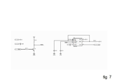
Fig.7 [Fig.7]
The input signal of this circuit is reversed by the Q7 transistor before entering the IC 555.
Fig.8 [Fig.8]
Bi-stable circuit to decide for turn on and off the LEDs.
Fig.9 [Fig.9]
LED driver circuit. In this circuit, the LEDs are divided into four categories and their cathodes are connected in each category.
Fig.10 [Fig.10]
Battery protection circuit to prevent overcharging and fast battery charging.
Fig.11 [Fig.11]
Battery charging voltage regulator circuit.
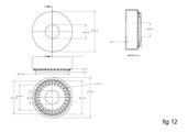
Fig.12 [Fig.12]
The technical map and the three faces of the product shell, along with the exact dimensions, are shown.
Fig.13 [Fig.13]
Flowchart device mechanism in a schematic.
In the following detailed description and specific embodiment is shown via illustration; afterwards, detailed description of embodiment declares in order to better comprehension of the invented plan and its detailed parts.
Mono-Stable Circuit with IC 555, Inverter Circuit and delay circuit. This circuit is detected by a three-gate NOT and one gate AND a rising edge.
Examples
This invented plan is a device that detects power outage and emergency lighting, which consists of a set of a number of LEDs and activate and the ability to produce light equivalent to two ordinary bulbs. In this method, the equivalent of the network resistor is considered from the side of socket and if it is finite, its quantity deduce the lack of current in a power outage network. Consequently, emergency lighting is activated and remains lit up until the main power is reconnected or switched off by the user. When the power is connected again, the emergency lighting is cut off and the battery in the device starts charging. The device provides the ability to turn the environment on and determine the emergency exits of the building when the electricity is cut off for the residents.
This design can be used for any space, such as home, work environment and public spaces, and more comprehensively wherever lighting is available.
Claims (12)
- What claims to be a bulb socket that includes: the process of detecting power outage and jumping fuses and environment lighting in the absence of electricity.
- According to claim 1, this socket consists of four parts; sockets, body, the electric circuit and the optical diode.
- According to claim 2, in case of switching on (key S1), intermittent urban power system is converted to direct current electricity by rectifier circuit.
- According to claim 3, the continuity of the current is checked by the relay (K2).
- According to claim 4, the user detects the key off or power outage by resistance processing, two-wire inputs to the socket-phase and null, upstream detection circuit, mono-stable circuit, with the IC 555, the inverter circuit and delay circuit are controlled automatically.
- According to claim 5, detection is this if the resistance between the phase and the null is infinite, this means that the circuit is open and the user has disconnected the key and the optical diodes in the circuit of the LED driver do not turn on.
- According to claim 6, if the resistance has a finite amount, it indicates that the key is still connected; however, the main power is disconnected and optical diode located in the circuit of the LED driver is turning on.
- According to claim 7, as soon as the power outage is resolved, the circuit for detection of falling edge causes the relay (K2) to return to its original state.
- According to claim 8, edge detection circuit orders to determiner block or bi-stable circuit and optical diode switches off automatically.
- According to claim 9, after the diodes are turned off, the battery charging (BT1) is started, which starts from the time the diode switches off and continues until the batteries are full.
- According to claim 10, battery protective circuit is used in order to prevent overcharging and increase battery life.
- According to claim 11, the voltage regulator circuit of the battery charging is used to adjust the voltage and limiting battery charge current.
Applications Claiming Priority (2)
| Application Number | Priority Date | Filing Date | Title |
|---|---|---|---|
| IR139750140003006779 | 2018-11-10 | ||
| IR13973006779 | 2018-11-10 |
Publications (1)
| Publication Number | Publication Date |
|---|---|
| WO2020095125A1 true WO2020095125A1 (en) | 2020-05-14 |
Family
ID=70725903
Family Applications (1)
| Application Number | Title | Priority Date | Filing Date |
|---|---|---|---|
| PCT/IB2019/057130 Ceased WO2020095125A1 (en) | 2018-11-10 | 2019-08-24 | Interface between socket and bulb with the ability to detect electric power outage and illuminate the environment |
Country Status (1)
| Country | Link |
|---|---|
| WO (1) | WO2020095125A1 (en) |
Cited By (1)
| Publication number | Priority date | Publication date | Assignee | Title |
|---|---|---|---|---|
| CN114689926A (en) * | 2020-12-25 | 2022-07-01 | 青岛海尔电冰箱有限公司 | Power failure detection method and device and electric equipment with same |
Citations (3)
| Publication number | Priority date | Publication date | Assignee | Title |
|---|---|---|---|---|
| US4392081A (en) * | 1981-07-31 | 1983-07-05 | General Electric Company | Lighting unit |
| WO2010127366A2 (en) * | 2009-05-01 | 2010-11-04 | Fulham Co. Ltd. | Supplemental, backup or emergency lighting systems and methods |
| JP2016100050A (en) * | 2014-11-18 | 2016-05-30 | 日本街路灯製造株式会社 | Street light equipment |
-
2019
- 2019-08-24 WO PCT/IB2019/057130 patent/WO2020095125A1/en not_active Ceased
Patent Citations (3)
| Publication number | Priority date | Publication date | Assignee | Title |
|---|---|---|---|---|
| US4392081A (en) * | 1981-07-31 | 1983-07-05 | General Electric Company | Lighting unit |
| WO2010127366A2 (en) * | 2009-05-01 | 2010-11-04 | Fulham Co. Ltd. | Supplemental, backup or emergency lighting systems and methods |
| JP2016100050A (en) * | 2014-11-18 | 2016-05-30 | 日本街路灯製造株式会社 | Street light equipment |
Cited By (1)
| Publication number | Priority date | Publication date | Assignee | Title |
|---|---|---|---|---|
| CN114689926A (en) * | 2020-12-25 | 2022-07-01 | 青岛海尔电冰箱有限公司 | Power failure detection method and device and electric equipment with same |
Similar Documents
| Publication | Publication Date | Title |
|---|---|---|
| CA2766422C (en) | Electronic circuit for converting a mains-operated luminaire into an emergency luminaire | |
| CN103262658B (en) | Fluorescent type LED lighting | |
| US10333344B2 (en) | Emergency backup systems providing dimmed power | |
| EP2909916B1 (en) | Led tube for emergency lighting system | |
| WO2020095125A1 (en) | Interface between socket and bulb with the ability to detect electric power outage and illuminate the environment | |
| WO2017089755A1 (en) | LED light fitting and emergency power supply therefor | |
| CN203027528U (en) | An uninterruptible power detection device | |
| KR100715282B1 (en) | Charge control device for battery for emergency lighting | |
| CN221575656U (en) | Automatic dimming detection circuit of emergency lighting device in inverter system | |
| JP5624268B2 (en) | Lighting device, lighting fixture | |
| US9093858B2 (en) | Illumination system and illumination driving method | |
| ITVI20130306A1 (en) | LIGHTING EQUIPMENT WITH EMBEDDED CIRCUIT FOR EMERGENCY LIGHTING | |
| KR20140005787U (en) | Auto switching light apparatus | |
| KR20130090852A (en) | Charging system for led illumination | |
| CN107658958B (en) | Photoelectric system and photoelectric control method | |
| US11510296B2 (en) | Linear solid-state lighting with a pulse train control | |
| US8076855B2 (en) | Combination emergency light and nightlight | |
| TWI713620B (en) | Lighting device and operating method thereof | |
| US20220131409A1 (en) | Dual power switching system | |
| KR101243694B1 (en) | Power storage apparatus comprising different storage battery type and solar streetlight using the same | |
| CN207720482U (en) | Full-automatic LED emergency light | |
| JP5977411B1 (en) | Lighting control device | |
| KR20130136236A (en) | Charging & discharging circuit for led emergency lamp with battery | |
| JP6029924B2 (en) | Lighting system | |
| KR20140137610A (en) | lighting control device of socket type LED lamp |
Legal Events
| Date | Code | Title | Description |
|---|---|---|---|
| 121 | Ep: the epo has been informed by wipo that ep was designated in this application |
Ref document number: 19882385 Country of ref document: EP Kind code of ref document: A1 |
|
| NENP | Non-entry into the national phase |
Ref country code: DE |
|
| 122 | Ep: pct application non-entry in european phase |
Ref document number: 19882385 Country of ref document: EP Kind code of ref document: A1 |