WO2018016371A1 - Heat exchanger - Google Patents
Heat exchanger Download PDFInfo
- Publication number
- WO2018016371A1 WO2018016371A1 PCT/JP2017/025164 JP2017025164W WO2018016371A1 WO 2018016371 A1 WO2018016371 A1 WO 2018016371A1 JP 2017025164 W JP2017025164 W JP 2017025164W WO 2018016371 A1 WO2018016371 A1 WO 2018016371A1
- Authority
- WO
- WIPO (PCT)
- Prior art keywords
- sheet
- flow path
- heat exchanger
- medium flow
- medium
- Prior art date
- Legal status (The legal status is an assumption and is not a legal conclusion. Google has not performed a legal analysis and makes no representation as to the accuracy of the status listed.)
- Ceased
Links
Images


Classifications
-
- F—MECHANICAL ENGINEERING; LIGHTING; HEATING; WEAPONS; BLASTING
- F28—HEAT EXCHANGE IN GENERAL
- F28D—HEAT-EXCHANGE APPARATUS, NOT PROVIDED FOR IN ANOTHER SUBCLASS, IN WHICH THE HEAT-EXCHANGE MEDIA DO NOT COME INTO DIRECT CONTACT
- F28D1/00—Heat-exchange apparatus having stationary conduit assemblies for one heat-exchange medium only, the media being in contact with different sides of the conduit wall, in which the other heat-exchange medium is a large body of fluid, e.g. domestic or motor car radiators
- F28D1/02—Heat-exchange apparatus having stationary conduit assemblies for one heat-exchange medium only, the media being in contact with different sides of the conduit wall, in which the other heat-exchange medium is a large body of fluid, e.g. domestic or motor car radiators with heat-exchange conduits immersed in the body of fluid
- F28D1/04—Heat-exchange apparatus having stationary conduit assemblies for one heat-exchange medium only, the media being in contact with different sides of the conduit wall, in which the other heat-exchange medium is a large body of fluid, e.g. domestic or motor car radiators with heat-exchange conduits immersed in the body of fluid with tubular conduits
- F28D1/053—Heat-exchange apparatus having stationary conduit assemblies for one heat-exchange medium only, the media being in contact with different sides of the conduit wall, in which the other heat-exchange medium is a large body of fluid, e.g. domestic or motor car radiators with heat-exchange conduits immersed in the body of fluid with tubular conduits the conduits being straight
-
- F—MECHANICAL ENGINEERING; LIGHTING; HEATING; WEAPONS; BLASTING
- F28—HEAT EXCHANGE IN GENERAL
- F28F—DETAILS OF HEAT-EXCHANGE AND HEAT-TRANSFER APPARATUS, OF GENERAL APPLICATION
- F28F1/00—Tubular elements; Assemblies of tubular elements
- F28F1/02—Tubular elements of cross-section which is non-circular
-
- F—MECHANICAL ENGINEERING; LIGHTING; HEATING; WEAPONS; BLASTING
- F28—HEAT EXCHANGE IN GENERAL
- F28F—DETAILS OF HEAT-EXCHANGE AND HEAT-TRANSFER APPARATUS, OF GENERAL APPLICATION
- F28F1/00—Tubular elements; Assemblies of tubular elements
- F28F1/10—Tubular elements and assemblies thereof with means for increasing heat-transfer area, e.g. with fins, with projections, with recesses
- F28F1/40—Tubular elements and assemblies thereof with means for increasing heat-transfer area, e.g. with fins, with projections, with recesses the means being only inside the tubular element
-
- F—MECHANICAL ENGINEERING; LIGHTING; HEATING; WEAPONS; BLASTING
- F28—HEAT EXCHANGE IN GENERAL
- F28F—DETAILS OF HEAT-EXCHANGE AND HEAT-TRANSFER APPARATUS, OF GENERAL APPLICATION
- F28F13/00—Arrangements for modifying heat-transfer, e.g. increasing, decreasing
- F28F13/06—Arrangements for modifying heat-transfer, e.g. increasing, decreasing by affecting the pattern of flow of the heat-exchange media
- F28F13/12—Arrangements for modifying heat-transfer, e.g. increasing, decreasing by affecting the pattern of flow of the heat-exchange media by creating turbulence, e.g. by stirring, by increasing the force of circulation
-
- F—MECHANICAL ENGINEERING; LIGHTING; HEATING; WEAPONS; BLASTING
- F28—HEAT EXCHANGE IN GENERAL
- F28F—DETAILS OF HEAT-EXCHANGE AND HEAT-TRANSFER APPARATUS, OF GENERAL APPLICATION
- F28F9/00—Casings; Header boxes; Auxiliary supports for elements; Auxiliary members within casings
- F28F9/02—Header boxes; End plates
Definitions
- the present invention relates to a stacked heat exchanger.
- JP2014-088994A discloses a heat exchanger tube that improves heat radiation performance while suppressing an increase in the flow resistance of the heat exchange medium by forming a wave-like channel.
- An object of the present invention is to provide a heat exchanger that can suppress an increase in flow resistance while improving heat dissipation performance.
- a heat exchanger is a stacked heat exchanger formed by laminating a plurality of tube sheets, and the tube sheet includes a pair of first and second sheets facing each other, and the first sheet Formed between one sheet and the second sheet, and is formed at one end of the first sheet and the second sheet so as to communicate with a medium flow path through which a heat exchange medium flows, and in the stacking direction, A heat transfer medium in a medium flow path in which the heat exchange medium flows in the stacking direction of the tube sheet, and at least one of the first sheet and the second sheet is formed to protrude into the medium flow path.
- the protrusion is formed to extend from one end of the first sheet or the second sheet in the heat exchange medium flow direction of the medium flow path, and the medium flow path and the stacking direction Medium flow Constituted by a stirring protrusions for stirring the heat exchange medium flowing a rectifying protrusion that adjust the flow of the heat exchange medium flows, the medium flow path between the.
- the heat exchange medium flowing between the medium flow path and the stacking direction medium flow path is guided to the rectifying protrusion formed so as to extend in the flow direction of the heat exchange medium in the medium flow path.
- the flow is arranged. Therefore, it is possible to suppress an increase in the flow resistance between the medium flow path and the stacking direction medium flow path that are orthogonal to each other and flow resistance is likely to increase.
- the heat exchange medium flowing through the medium flow path after the flow is adjusted by the rectifying protrusion is stirred in the medium flow path by the stirring protrusion.
- the heat exchange medium flowing through the medium flow path can easily exchange heat with an external fluid via the tube sheet. Therefore, the heat exchanger which can suppress the increase in distribution resistance more while improving heat dissipation performance can be provided.
- FIG. 1 is a schematic configuration diagram of a stacked heat exchanger according to an embodiment of the present invention.
- FIG. 2 is an exploded view of the heat exchanger.
- FIG. 3 is an exploded view of the core.
- FIG. 4 is a plan view of the tube sheet.
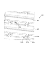
- FIG. 5 is a perspective view showing the vicinity of the end of the rectifying protrusion of the tube sheet.
- FIG. 6 is a plan view of a tube sheet according to a modification.
- FIG. 7 is a plan view of a tube sheet according to a second modification.
- FIG. 8 is a plan view of a tube sheet according to a third modification.
- FIG. 9 is a plan view of a tube sheet according to a fourth modification.
- FIG. 10 is a plan view of a tube sheet of a heat exchanger according to a comparative example.
- FIG. 11 is a perspective view showing the vicinity of the end of the stirring protrusion of the heat exchanger according to the comparative example.
- FIG. 1 is a schematic configuration diagram of a stacked heat exchanger 100 according to an embodiment of the present invention.
- FIG. 2 is an exploded view of the heat exchanger 100
- FIG. 3 is an exploded view of the core 10.
- FIG. 4 is a plan view of the tube sheet 20
- FIG. 5 is a perspective view showing the vicinity of the end portion 26 c of the rectifying protrusion 26 a of the tube sheet 20.
- the heat exchanger 100 includes a core 10 formed by stacking a plurality of tube sheets 20 and a base member 30 attached to the core 10 as shown in FIGS. 1 and 2.
- the heat exchanger 100 is installed, for example, in an intake passage of an engine (not shown).
- the base member 30 has an upstream pipe 31 connected to the upstream side of the flow path of the engine coolant and a downstream pipe 32 connected to the downstream side of the flow path.
- the core 10 includes a plurality of stacked tube sheets 20 and corrugated fins 11 disposed between the tube sheets 20.
- the surface area of the core 10 is expanded, and the heat exchange efficiency is increased.
- the tube sheet 20 includes a pair of first sheet 21 and second sheet 22 that face each other.
- the first sheet 21 and the second sheet 22 are formed by press molding, for example. As shown in FIGS. 3 and 4, the first sheet 21 and the second sheet 22 are formed in a tray shape having a bottom surface 23 and a flange 24 formed on the outer peripheral edge of the bottom surface 23. A burring 25 is formed in a part near the outer peripheral edge of the bottom surface 23, and a protrusion 26 is formed in the center so as to extend toward the burring 25.
- a medium flow path 40 through which cooling water as a heat exchange medium flows is formed.
- the burrings 25 of the adjacent tube sheets 20 are connected to form a space as a tank in the stacking direction of the tube sheets 20.
- the space functions as a stacking direction medium flow path 41 in which the cooling water of the medium flow path 40 flows in the stacking direction of the tube sheets 20. Therefore, the stacking direction medium flow path 41 is formed at one end of the first sheet 21 and the second sheet 22 so as to communicate with each other in the stacking direction.
- stacked is performed by, for example, covering the part which each tube sheet 20 contacts previously with a brazing material, and brazing and fixing integrally in a furnace in the assembled state. .
- the stacking direction medium flow path 41 communicates with the upstream pipe 31 and flows into the core 10 and flows in the cooling water into the core 10.
- the laminating direction medium flow path 41 communicates with the downstream pipe 32 and flows out to flow out the cooling water in the core 10.
- the side flow path 41b and the circulation flow path 41c for circulating the cooling water in the stacking direction of the tube sheet 20 are included.
- the protruding portion 26 is formed on the first sheet 21 and the second sheet 22 so as to protrude into the medium flow path 40.
- the first sheet 21 and the second sheet 22 are formed to have the same shape.
- the protruding portion 26 is a flow of cooling water that circulates between the agitating protruding portion 26 b that stirs the cooling water flowing through the medium flow path 40, and the inflow side flow path 41 a or the outflow side flow path 41 b and the medium flow path 40. And a rectifying protrusion 26a for adjusting the flow rate.
- the agitation protrusion 26b is bent and formed on the first sheet 21 and the second sheet 22 so as to have a wave shape with the same period. For this reason, the protrusions 26b for stirring formed on the first sheet 21 and the second sheet 22 are overlapped in an inverted state by stacking the first sheet 21 and the second sheet 22 so as to face each other. The pair of stirring protrusions 26b that are overlapped with each other come into contact with each other at each wave node. In this manner, the stirring protrusions 26b protrude so as to be half the thickness of the medium flow path 40, respectively, and block a part of the medium flow path 40.
- the cooling water in the medium flow path 40 flows in the planar direction along the wavy shape of the pair of stirring protrusions 26b, and the thickness of the medium flow path 40 exceeds the respective stirring protrusions 26b. After being separated into the flow in the stacking direction flowing in the direction (stacking direction), the flow is mixed again.
- the rectifying protrusion 26 a is formed so as to extend linearly from one end of the first sheet 21 or the second sheet 22 in the cooling water flow direction of the medium flow path 40.
- the straightening protrusion 26a has one end extending toward the first sheet 21 or the second sheet 22 and the other end smoothly connected to the stirring protrusion 26b. Therefore, the cooling water flowing between the stack direction medium flow path 41 and the medium flow path 40 is guided to the rectifying protrusion 26a formed to extend linearly in the flow direction of the cooling water in the medium flow path. The flow is arranged.
- the rectifying protrusions 26 a formed on the first sheet 21 and the second sheet 22 are stacked so that the first sheet 21 and the second sheet 22 are opposed to each other. It overlaps so that 26d may contact
- the protruding end 26d of the rectifying protruding portion 26a of the first sheet 21 and the second sheet 22 is formed in a flat surface shape, and abuts each protruding end 26d facing each other so that the surface is in close contact. .
- the first sheet 21 and the second sheet 22 are bonded to each other by forming the straightening protrusions 26a on the first sheet 21 and the second sheet 22 so as to have the protruding ends 26d facing each other. Wide area is secured.
- FIG. 10 is a plan view of the tube sheet 920 of the heat exchanger 900 according to the comparative example
- FIG. 11 is a perspective view showing the vicinity of the end 926c of the stirring protrusion 926b of the heat exchanger 900 according to the comparative example.
- the heat exchanger 900 according to the comparative example does not have the rectifying protrusion 26 a unlike the heat exchanger 100 of the above embodiment. Therefore, the cooling water flowing between the medium flow path 940 and the stacking direction medium flow path 941 is not guided between the orthogonal medium flow path 940 and the stacking direction medium flow path 941 and the flow of the cooling water flowing between the medium flow path 940 and the stacking direction medium flow path 941. I can't arrange it. Further, in the heat exchanger 900 according to the comparative example, since the stirring protrusion 926b is formed up to one end of the first sheet 921 and the second sheet 922, as shown in FIG. 10 and FIG.
- the first sheet 921 and the second sheet 922 are in contact with each other only at the node portion of the stirring protrusion 926b. Therefore, it becomes difficult to secure a sufficient joint surface for bringing the first sheet 921 and the second sheet 922 into close contact with each other.
- the heat exchanger 100 is a stacked heat exchanger formed by laminating a plurality of tube sheets 20, and the tube sheet 20 includes a pair of first and second sheets 21, 22, and a first sheet 21. Formed between the first sheet 21 and the second sheet 22 and formed at one end of the first sheet 21 and the second sheet 22 so as to communicate with the medium flow path 40 through which cooling water as a heat exchange medium flows. And a stacking direction medium flow path 41 in which the cooling water of the medium flow path 40 flows in the stacking direction of the tube sheet 20. At least one of the first sheet 21 and the second sheet 22 has a protruding portion 26 formed so as to protrude into the medium flow path 40.
- the protrusion 26 is formed to extend from one end of the first sheet 21 or the second sheet 22 in the flow direction of the cooling water in the medium flow path 40, and flows between the medium flow path 40 and the stacking direction medium flow path 41.
- the rectifying protrusion 26a for adjusting the flow of the cooling water to be performed and the agitation protrusion 26b for stirring the cooling water flowing through the medium flow path 40 are configured.
- the cooling water as the heat exchange medium flowing between the medium flow path 40 and the stacking direction medium flow path 41 extends in the flow direction of the cooling water in the medium flow path 40.
- the flow is adjusted by being guided by the rectifying protrusion 26a that is formed to protrude to the right. Therefore, it is possible to suppress an increase in the flow resistance between the medium flow path 40 and the stacking direction medium flow path 41, which are orthogonal to each other and flow resistance is likely to increase.
- the cooling water flowing through the medium flow path 40 after the flow is adjusted by the rectifying protrusion 26a, the medium flow path is formed by the stirring protrusion 26b formed so as to block the flow of the cooling water in the medium flow path 40. Stir in 40.
- the cooling water flowing through the medium flow path 40 can easily exchange heat with the sucked air that is an external fluid via the tube sheet 20. Therefore, it is possible to provide the heat exchanger 100 that can further suppress an increase in distribution resistance while improving the heat dissipation performance.
- At least one end 26c of the rectifying protrusion 26a of the heat exchanger 100 extends linearly toward the flow direction of the cooling water in the medium flow path 40.
- the flow can be adjusted so that the cooling water flows stably and straightly in the flow direction of the cooling water in the medium flow path 40 by the straightening protrusions 26a extending linearly. Therefore, similarly, it is possible to provide the heat exchanger 100 that can further suppress the increase in flow resistance while improving the heat dissipation performance.
- the first sheet 21 is formed with a rectifying protrusion 26a.
- the second sheet 22 is formed with a rectifying protrusion 26 a having the same shape as the rectifying protrusion 26 a of the first sheet 21.
- the rectifying protrusions 26a of the first sheet 21 and the second sheet 22 are stacked so that the protruding ends 26d abut each other by stacking the first sheet 21 and the second sheet 22 so as to face each other. Therefore, since the protruding end 26d of the rectifying protruding portion 26a can be brought into close contact with each other, the bonding strength between the first sheet 21 and the second sheet 22 can be increased.
- the stirring protrusion 26b bends in a wave shape. Therefore, the stirring protrusion 26b of the first sheet 21 and the second sheet 22 can be stirred so as to repeat separation and mixing by guiding the cooling water in the medium flow path 40 in a wave shape. Moreover, the heat exchange efficiency of the cooling water between the air and the fin 11 can be increased.
- the first sheet 21 and the second sheet 22 are respectively formed with the protruding portions 26b for stirring having the same shape.
- the stirring protrusion 26b is formed by laminating the first sheet 21 and the second sheet 22 so as to face each other, so that the wavy nodes overlap with each other in a state of being inverted.
- the cooling water flowing through the medium flow path 40 also flows in the thickness direction of the medium flow path 40 so as to pass over portions (particularly antinodes) other than the wavy nodes of the stirring protrusions 26b.
- the cooling water in 40 can be stirred more efficiently. Therefore, the heat exchange efficiency of the cooling water between the air through the bottom surface 23 and the fins 11 can be further increased.
- the protrusion 26 may be formed only on one of the first sheet 21 and the second sheet 22. Further, the protruding portion 26 of the first sheet 21 may be formed to have a different shape from the protruding portion 26 of the second sheet 22.
- the rectifying protrusion 226a may be formed so as to adjust the flow of the cooling water flowing between the circulation channel 41c and the medium channel 40 as shown in FIG.
- FIG. 6 is a plan view of a tube sheet 220 according to a modification.
- the rectifying protrusion 226a and the rectifying protrusion 226a are smoothly connected to both ends of the stirring protrusion 226b. According to such an aspect, the cooling water flowing between the circulation flow path 41c and the medium flow path 40 is guided by the rectifying protrusion 226a to adjust the flow, so that the circulation flow path 41c and the medium flow path are adjusted. An increase in the flow resistance between 40 and 40 can also be suppressed.
- FIG. 7 is a plan view of the tube sheet 320 according to the second modification
- FIG. 8 is a plan view of the tube sheet 420 according to the third modification.
- the medium flow path 340 is formed in a U shape.
- the cooling water flowing into the medium flow path 340 from the inflow side flow path 341a flows out of the outflow side flow path 341b after flowing through the medium flow path 340 in a U shape.
- the stirring protrusion 326b according to the second modification is formed on the bottom surface 323 of the tube sheet 320 so as to be line symmetric as shown in FIG. Therefore, by laminating the first sheet 321 and the second sheet 322 of the tube sheet 320 according to the second modification so as to face each other, the agitation protrusions 326b overlap so that the protrusion ends 326c abut each other. Therefore, not only the protruding end 326d of the rectifying protruding portion 326a but also the protruding end 326c of the stirring protruding portion 326b can be brought into close contact with each other, so that the bonding strength between the first sheet 321 and the second sheet 322 can be further increased. Can be increased.
- the tube sheet 420 according to the third modification also has a medium flow path 440 formed in a U shape.
- the cooling water flowing into the medium flow path 440 from the inflow side flow path 441a flows out of the outflow side flow path 441b after flowing through the medium flow path 440 in a U shape.
- the stirring protrusion 426b according to the third modification is formed on the bottom surface 423 of the tube sheet 420 so as to be non-symmetrical as shown in FIG. Therefore, when the first sheet 421 and the second sheet 422 of the tube sheet 420 according to the third modification are stacked so as to face each other, the stirring protrusion 426b does not contact the facing stirring protrusion 426b.
- the flow path 440 is half blocked in the thickness direction. Therefore, since the cooling water flowing through the medium flow path 440 is easily stirred in the thickness direction and the width direction of the medium flow path 440 by the respective stirring protrusions 426b, the heat exchange efficiency of the cooling water can be increased. .
- the stirring protrusion 526b may be formed in a fin shape as shown in FIG.
- FIG. 9 is a plan view of a tube sheet 520 according to a fourth modification.
- the cooling water flowing through the medium flow path 540 can also be efficiently stirred by the stirring protrusion 526b formed in such a fin shape.
Landscapes
- Engineering & Computer Science (AREA)
- Physics & Mathematics (AREA)
- Thermal Sciences (AREA)
- Mechanical Engineering (AREA)
- General Engineering & Computer Science (AREA)
- Geometry (AREA)
- Heat-Exchange Devices With Radiators And Conduit Assemblies (AREA)
Abstract
Description
本発明は、積層型の熱交換器に関する。 The present invention relates to a stacked heat exchanger.
JP2014-088994Aには、波状の流路を形成することによって熱交換媒体の流通抵抗の増加を抑えつつ放熱性能を向上させる熱交換器用チューブが開示されている。 JP2014-088994A discloses a heat exchanger tube that improves heat radiation performance while suppressing an increase in the flow resistance of the heat exchange medium by forming a wave-like channel.
しかしながら、JP2014-088994Aの熱交換器用チューブでは、熱交換媒体の流れを考慮して最適な流路が形成されているとはいえず、流通抵抗の増加を抑制できる余地をなお残している。 However, in the tube for heat exchanger of JP2014-088994A, an optimal flow path is not formed in consideration of the flow of the heat exchange medium, and there is still room for suppressing an increase in flow resistance.
本発明は、放熱性能を向上させつつ流通抵抗の増加をより抑えることのできる熱交換器を提供することを目的とする。 An object of the present invention is to provide a heat exchanger that can suppress an increase in flow resistance while improving heat dissipation performance.
本発明のある態様による熱交換器は、複数のチューブシートを積層してなる積層型の熱交換器であって、前記チューブシートは、対向する一対の第1シートおよび第2シートと、前記第1シートと前記第2シートとの間に形成され、内部に熱交換媒体が流通する媒体流路と、積層方向に連通するように前記第1シートおよび前記第2シートの一端に形成され、前記媒体流路の熱交換媒体が前記チューブシートの積層方向に流れる積層方向媒体流路と、を備え、前記第1シートおよび前記第2シートの少なくとも一方は、前記媒体流路に突出するよう形成される突出部を有し、前記突出部は、前記第1シートまたは前記第2シートの一端から前記媒体流路の熱交換媒体の流れ方向に延びるように形成され、前記媒体流路と前記積層方向媒体流路との間を流通する熱交換媒体の流れを整える整流用突出部と、前記媒体流路を流通する熱交換媒体を撹拌する撹拌用突出部と、から構成される。 A heat exchanger according to an aspect of the present invention is a stacked heat exchanger formed by laminating a plurality of tube sheets, and the tube sheet includes a pair of first and second sheets facing each other, and the first sheet Formed between one sheet and the second sheet, and is formed at one end of the first sheet and the second sheet so as to communicate with a medium flow path through which a heat exchange medium flows, and in the stacking direction, A heat transfer medium in a medium flow path in which the heat exchange medium flows in the stacking direction of the tube sheet, and at least one of the first sheet and the second sheet is formed to protrude into the medium flow path. And the protrusion is formed to extend from one end of the first sheet or the second sheet in the heat exchange medium flow direction of the medium flow path, and the medium flow path and the stacking direction Medium flow Constituted by a stirring protrusions for stirring the heat exchange medium flowing a rectifying protrusion that adjust the flow of the heat exchange medium flows, the medium flow path between the.
上記態様によれば、媒体流路と積層方向媒体流路との間を流通する熱交換媒体は、媒体流路の熱交換媒体の流れ方向に延びるように突出形成された整流用突出部に案内されることによって、流れが整えられる。そのため、直交する流れとなり流通抵抗が増加しやすい媒体流路と積層方向媒体流路との間における流通抵抗の増加を抑制することができる。また、整流用突出部によって流れが整えられた後に媒体流路を流通する熱交換媒体は、撹拌用突出部によって媒体流路内で撹拌される。その結果、媒体流路を流通する熱交換媒体がチューブシートを介して外部の流体と熱交換を行いやすくなる。したがって、放熱性能を向上させつつ流通抵抗の増加をより抑えることのできる熱交換器を提供することができる。 According to the above aspect, the heat exchange medium flowing between the medium flow path and the stacking direction medium flow path is guided to the rectifying protrusion formed so as to extend in the flow direction of the heat exchange medium in the medium flow path. By doing so, the flow is arranged. Therefore, it is possible to suppress an increase in the flow resistance between the medium flow path and the stacking direction medium flow path that are orthogonal to each other and flow resistance is likely to increase. In addition, the heat exchange medium flowing through the medium flow path after the flow is adjusted by the rectifying protrusion is stirred in the medium flow path by the stirring protrusion. As a result, the heat exchange medium flowing through the medium flow path can easily exchange heat with an external fluid via the tube sheet. Therefore, the heat exchanger which can suppress the increase in distribution resistance more while improving heat dissipation performance can be provided.
以下、図面を参照して、本発明の実施形態について説明する。 Hereinafter, embodiments of the present invention will be described with reference to the drawings.
図1は、本発明の実施形態に係る積層型の熱交換器100の概略構成図である。図2は熱交換器100を分解した図であり、図3はコア10を分解した図である。図4はチューブシート20の平面図であり、図5は、チューブシート20の整流用突出部26aの端部26c付近を示す斜視図である。
FIG. 1 is a schematic configuration diagram of a stacked
熱交換器100は、図1および図2に示すように、複数のチューブシート20を積層してなるコア10と、コア10に取り付けられるベース部材30と、を備える。熱交換器100は、例えば、図示しないエンジンの吸気通路内に設置される。
The
ベース部材30は、エンジンの冷却水の流通流路の上流側に接続される上流側パイプ31と、流路の下流側に接続される下流側パイプ32と、を有する。これにより、エアインテークマニホールド内に吸入した空気がコア10を通過するときに、冷却水との間で熱交換が行われ、吸入した空気が冷却される。
The
コア10は、図3に示すように、複数の積層されたチューブシート20と、チューブシート20の間に配設されるコルゲート状のフィン11と、を有する。フィン11を備えることによってコア10の表面積が拡大し、熱交換効率が高くなる。
As shown in FIG. 3, the
チューブシート20は、対向する一対の第1シート21と第2シート22とから構成される。
The
第1シート21および第2シート22は、例えば、プレス成形によって形成される。第1シート21および第2シート22には、図3および図4に示すように、底面23と、底面23の外周縁に形成されるフランジ24と、を有するトレイ状に形成される。底面23の外周縁付近の一部にはバーリング25が形成され、中央部にはバーリング25に向かって延びるように突出部26が形成される。
The
また、チューブシート20の内部、すなわち第1シート21と第2シート22とによって囲まれた扁平な空間には、熱交換媒体としての冷却水が流通する媒体流路40が形成される。このように形成することによって熱交換器100の作動時に、媒体流路40を流通する冷却水と吸入した空気との間でチューブシート20の底面23やフィン11を介した熱交換が行われる。なお、冷却水には、例えば不凍液が用いられる。
Further, in the flat space surrounded by the
図2に示すように複数のチューブシート20を積層させることによって、隣接するチューブシート20のバーリング25が連なって、チューブシート20の積層方向にタンクとしての空間を形成する。当該空間は、媒体流路40の冷却水がチューブシート20の積層方向に流れる積層方向媒体流路41として機能する。したがって、積層方向媒体流路41は、積層方向に連通するように第1シート21および第2シート22の一端に形成されることになる。なお、積層させた各チューブシート20間の接合は、例えば、各チューブシート20が接触する部分に予めロウ材を被覆し、組み立てた状態で炉内にて一体にロウ付け固定することによって行われる。
2, by stacking a plurality of
積層方向媒体流路41は、上流側パイプ31と連通してコア10内に冷却水を流入させる流入側流路41aと、下流側パイプ32と連通してコア10内の冷却水を流出させる流出側流路41bと、チューブシート20の積層方向に冷却水を循環させる循環流路41cと、からなる。
The stacking direction
突出部26は、媒体流路40に突出するように第1シート21および第2シート22に形成される。第1シート21と第2シート22とは、同一の形状となるように形成される。
The protruding
突出部26は、媒体流路40を流通する冷却水を撹拌する撹拌用突出部26bと、流入側流路41aまたは流出側流路41bと媒体流路40との間を流通する冷却水の流れを整える整流用突出部26aと、から構成される。
The protruding
撹拌用突出部26bは、第1シート21および第2シート22に同一周期の波状になるように屈曲形成される。このため、第1シート21および第2シート22に形成される撹拌用突出部26bは、第1シート21および第2シート22を対向するように積層させることで、互いに反転した状態で重なり合う。そして、重なり合った一対の撹拌用突出部26bは、それぞれの波の節の部分で互いに当接する。このように、撹拌用突出部26bは、それぞれ媒体流路40の厚みの半分の高さとなるように突出して、媒体流路40の一部を遮る。
The
その結果、媒体流路40の冷却水は、一対の撹拌用突出部26bの波状の形状に沿って流れる平面方向の流れと、それぞれの撹拌用突出部26bを越えるように媒体流路40の厚み方向(積層方向)に流れる積層方向の流れと、に分離された後、再び混合されるような流れを繰り返す。
As a result, the cooling water in the
整流用突出部26aは、第1シート21または第2シート22の一端から媒体流路40の冷却水の流れ方向に直線状に延びるように形成される。具体的には、整流用突出部26aは、一端が第1シート21または第2シート22に向かって延び、他端が撹拌用突出部26bに滑らかに接続される。したがって、積層方向媒体流路41と媒体流路40との間を流通する冷却水は、媒体流路の冷却水の流れ方向に直線状に延びるように形成された整流用突出部26aに案内されることによって、流れが整えられる。
The rectifying
第1シート21および第2シート22に形成される整流用突出部26aは、図5に示すように、第1シート21および第2シート22を対向するように積層させることで、それぞれの突出端26dが当接するように重なり合う。第1シート21および第2シート22の整流用突出部26aの突出端26dは、表面が平坦な面状に形成されており、対向するそれぞれの突出端26dと当該表面が密着するように当接する。このように、対向する突出端26dを備えるように整流用突出部26aを第1シート21および第2シート22に形成することによって、第1シート21と第2シート22とを密着させるための接合面が広く確保される。
As shown in FIG. 5, the rectifying
これに対して、図10および図11に示すような比較例に係る熱交換器900の場合には、撹拌用突出部926bが第1シート921および第2シート922の一端まで形成されている。図10は比較例に係る熱交換器900のチューブシート920の平面図であり、図11は比較例に係る熱交換器900の撹拌用突出部926bの端部926c付近を示す斜視図である。
On the other hand, in the case of the
比較例に係る熱交換器900は、図10に示すように、上記実施形態の熱交換器100のように整流用突出部26aを有していない。そのため、直交する媒体流路940と積層方向媒体流路941との間における冷却水が案内されることがなく、媒体流路940と積層方向媒体流路941との間を流通する冷却水の流れを整えることができない。また、比較例に係る熱交換器900は、撹拌用突出部926bが第1シート921および第2シート922の一端まで形成されているので、図10および図11に示すように、対向する波状の撹拌用突出部926bにおける節の部分のみで第1シート921と第2シート922とは互いに当接することなる。そのため、第1シート921と第2シート922とを密着させるための接合面を十分に確保することが難しくなる。
As shown in FIG. 10, the
以上の実施形態によれば、以下に示す効果を奏する。 According to the above embodiment, the following effects are obtained.
熱交換器100は、複数のチューブシート20を積層してなる積層型の熱交換器であって、チューブシート20は、対向する一対の第1シート21および第2シート22と、第1シート21と第2シート22との間に形成され、内部に熱交換媒体としての冷却水が流通する媒体流路40と、積層方向に連通するように第1シート21および第2シート22の一端に形成され、媒体流路40の冷却水がチューブシート20の積層方向に流れる積層方向媒体流路41と、を備える。第1シート21および第2シート22の少なくとも一方は、媒体流路40に突出するよう形成される突出部26を有する。突出部26は、第1シート21または第2シート22の一端から媒体流路40の冷却水の流れ方向に延びるように形成され、媒体流路40と積層方向媒体流路41との間を流通する冷却水の流れを整える整流用突出部26aと、媒体流路40を流通する冷却水を撹拌する撹拌用突出部26bと、から構成される。
The
このような熱交換器100によれば、媒体流路40と積層方向媒体流路41との間を流通する熱交換媒体としての冷却水は、媒体流路40の冷却水の流れ方向に延びるように突出形成された整流用突出部26aに案内されることによって、流れが整えられる。そのため、直交する流れとなり流通抵抗が増加しやすい媒体流路40と積層方向媒体流路41との間における流通抵抗の増加を抑制することができる。また、整流用突出部26aによって流れが整えられた後に媒体流路40を流通する冷却水は、媒体流路40の冷却水の流れを遮るように形成された撹拌用突出部26bによって媒体流路40内で撹拌される。その結果、媒体流路40を流通する冷却水がチューブシート20を介して外部の流体である吸入した空気と熱交換を行いやすくなる。したがって、放熱性能を向上させつつ流通抵抗の増加をより抑えることのできる熱交換器100を提供することができる。
According to such a
また、熱交換器100の整流用突出部26aは、少なくとも一方の端部26cが媒体流路40の冷却水の流れ方向に向かって直線状に延びる。その結果、直線状に延びる整流用突出部26aによって、冷却水が媒体流路40の冷却水の流れ方向に向かって安定して真っ直ぐ流れるように、流れを整えることができる。したがって、同様に、放熱性能を向上させつつ流通抵抗の増加をより抑えることのできる熱交換器100を提供することができる。
Further, at least one
さらに、熱交換器100では、第1シート21には、整流用突出部26aが形成される。第2シート22には、第1シート21の整流用突出部26aと同一形状の整流用突出部26aが形成される。第1シート21および第2シート22の整流用突出部26aは、第1シート21および第2シート22を対向するように積層させることで、互いに突出端26dが当接するように重なり合う。そのため、整流用突出部26aの突出端26dを密着させて接合することができるので、第1シート21と第2シート22との接合強度を高めることができる。
Furthermore, in the
また、熱交換器100では、撹拌用突出部26bは、波状に屈曲する。そのため、第1シート21および第2シート22の撹拌用突出部26bによって、媒体流路40の冷却水を波状に案内することで分離と混合とを繰り返すように撹拌することができるので、底面23やフィン11を介して空気との間における冷却水の熱交換効率を高くすることができる。
Moreover, in the
さらに、熱交換器100では、第1シート21および第2シート22には、同一形状の撹拌用突出部26bがそれぞれ形成される。撹拌用突出部26bは、第1シート21および第2シート22を対向するように積層させることで、互いに反転した状態で波状の節と節とが重なり合う。そのため、媒体流路40を流通する冷却水は、それぞれの撹拌用突出部26bの波状の節以外の部分(特に腹)を越えるように媒体流路40の厚み方向にも流れるので、媒体流路40内における冷却水をより効率よく撹拌することができる。したがって、底面23やフィン11を介して空気との間における冷却水の熱交換効率をより高くすることができる。
Furthermore, in the
なお、突出部26は、第1シート21および第2シート22の一方のみに形成されることとしてもよい。また、第1シート21の突出部26は、第2シート22の突出部26と異なる形状となるように形成されてもよい。
The
以上、本発明の実施形態について説明したが、上記実施形態は本発明の適用例の一部を示したに過ぎず、本発明の技術的範囲を上記実施形態の具体的構成に限定する趣旨ではない。 The embodiment of the present invention has been described above. However, the above embodiment only shows a part of application examples of the present invention, and the technical scope of the present invention is limited to the specific configuration of the above embodiment. Absent.
例えば、整流用突出部226aは、図6に示すように、循環流路41cと媒体流路40との間を流通する冷却水の流れを整えるように形成されてもよい。図6は、変形例に係るチューブシート220の平面図である。
For example, the rectifying
撹拌用突出部226bの両端には、整流用突出部226aと整流用突出部226aとがそれぞれ滑らかに接続されることになる。このような態様によれば、循環流路41cと媒体流路40との間を流通する冷却水は、整流用突出部226aに案内されて流れが整えられるので、循環流路41cと媒体流路40との間における流通抵抗の増加も抑制することができる。
The rectifying
また、撹拌用突出部326bは、図7や図8に示すように、円柱状に複数形成されてもよい。図7は第2の変形例に係るチューブシート320の平面図であり、図8は第3の変形例に係るチューブシート420の平面図である。
Also, as shown in FIGS. 7 and 8, a plurality of stirring
第2の変形例に係るチューブシート320では、媒体流路340がU字状に形成されている。流入側流路341aから媒体流路340へと流入した冷却水は、媒体流路340をU字状に流通した後、流出側流路341bから流出する。
In the
第2の変形例に係る撹拌用突出部326bは、図7に示すように、チューブシート320の底面323上に線対称となるように形成される。そのため、第2変形例に係るチューブシート320の第1シート321および第2シート322を対向するように積層させることで、撹拌用突出部326bは互いに突出端326cが当接するように重なり合う。そのため、整流用突出部326aの突出端326dだけでなく、撹拌用突出部326bの突出端326cも密着させて接合することができるので、第1シート321と第2シート322との接合強度をより高めることができる。
The stirring
第3変形例に係るチューブシート420も、第2変形例に係るチューブシート320と同様に、媒体流路440がU字状に形成されている。流入側流路441aから媒体流路440へと流入した冷却水は、媒体流路440をU字状に流通した後、流出側流路441bから流出する。
Similarly to the
第3の変形例に係る撹拌用突出部426bは、図8に示すように、チューブシート420の底面423上に非線対称となるように形成される。そのため、第3変形例に係るチューブシート420の第1シート421および第2シート422を対向するように積層させると、撹拌用突出部426bは、対向する撹拌用突出部426bと当接することなく媒体流路440の厚み方向に半分遮ることとなる。したがって、媒体流路440を流通する冷却水は、それぞれの撹拌用突出部426bによって媒体流路440の厚み方向や幅方向に撹拌され易くなるので、冷却水の熱交換効率を高くすることができる。
The stirring
さらに、撹拌用突出部526bは、図9に示すように、フィン状に形成してもよい。図9は、第4の変形例に係るチューブシート520の平面図である。このようなフィン状に形成した撹拌用突出部526bによっても、媒体流路540を流通する冷却水を効率よく撹拌することができる。
Further, the stirring
本願は、2016年7月19日に日本国特許庁に出願された特願2016-141676に基づく優先権を主張し、この出願の全ての内容は参照により本明細書に組み込まれる。 This application claims priority based on Japanese Patent Application No. 2016-141676 filed with the Japan Patent Office on July 19, 2016, the entire contents of which are incorporated herein by reference.
Claims (6)
前記チューブシートは、
対向する一対の第1シートおよび第2シートと、
前記第1シートと前記第2シートとの間に形成され、内部に熱交換媒体が流通する媒体流路と、
積層方向に連通するように前記第1シートおよび前記第2シートの一端に形成され、前記媒体流路の熱交換媒体が前記チューブシートの積層方向に流れる積層方向媒体流路と、
を備え、
前記第1シートおよび前記第2シートの少なくとも一方は、前記媒体流路に突出するよう形成される突出部を有し、
前記突出部は、
前記第1シートまたは前記第2シートの一端から前記媒体流路の熱交換媒体の流れ方向に延びるように形成され、前記媒体流路と前記積層方向媒体流路との間を流通する熱交換媒体の流れを整える整流用突出部と、
前記媒体流路を流通する熱交換媒体を撹拌する撹拌用突出部と、
から構成される、熱交換器。 A laminated heat exchanger in which a plurality of tube sheets are laminated,
The tube sheet is
A pair of opposing first and second sheets;
A medium flow path formed between the first sheet and the second sheet, in which a heat exchange medium flows;
A lamination direction medium flow path formed at one end of the first sheet and the second sheet so as to communicate in the lamination direction, and the heat exchange medium of the medium flow path flows in the lamination direction of the tube sheet;
With
At least one of the first sheet and the second sheet has a protrusion formed to protrude into the medium flow path,
The protrusion is
A heat exchange medium formed so as to extend from one end of the first sheet or the second sheet in the flow direction of the heat exchange medium in the medium flow path and circulates between the medium flow path and the stacking direction medium flow path A rectifying projection that regulates the flow of
A stirring protrusion for stirring the heat exchange medium flowing through the medium flow path;
A heat exchanger composed of
前記整流用突出部は、少なくとも一方の端部が前記媒体流路の熱交換媒体の流れ方向に向かって直線状に延びる、
熱交換器。 The heat exchanger according to claim 1,
The rectifying protrusion has at least one end extending linearly toward the flow direction of the heat exchange medium in the medium flow path,
Heat exchanger.
前記第1シートおよび前記第2シートには、同一形状の前記整流用突出部がそれぞれ形成され、
前記整流用突出部は、前記第1シートおよび前記第2シートを対向するように積層させることで、互いに突出端が当接するように重なり合う、
熱交換器。 The heat exchanger according to claim 2,
In the first sheet and the second sheet, the rectifying protrusions having the same shape are respectively formed.
The rectifying protrusions are stacked so that the protruding ends abut each other by laminating the first sheet and the second sheet so as to face each other.
Heat exchanger.
前記撹拌用突出部は、波状に屈曲する、
熱交換器。 The heat exchanger according to any one of claims 1 to 3,
The stirring protrusion is bent in a wave shape,
Heat exchanger.
前記撹拌用突出部は、円柱状に複数形成される、
熱交換器。 The heat exchanger according to any one of claims 1 to 3,
A plurality of the stirring protrusions are formed in a columnar shape,
Heat exchanger.
前記第1シートおよび前記第2シートには、同一形状の前記撹拌用突出部がそれぞれ形成され、
前記撹拌用突出部は、前記第1シートおよび前記第2シートを対向するように積層させることで、互いに反転した状態で重なり合う、
熱交換器。 A heat exchanger according to any one of claims 1 to 5,
The first sheet and the second sheet are respectively formed with the stirring protrusions having the same shape,
The stirring protrusions are stacked so that the first sheet and the second sheet are opposed to each other so as to be reversed with respect to each other.
Heat exchanger.
Applications Claiming Priority (2)
| Application Number | Priority Date | Filing Date | Title |
|---|---|---|---|
| JP2016141676A JP2018013262A (en) | 2016-07-19 | 2016-07-19 | Heat exchanger |
| JP2016-141676 | 2016-07-19 |
Publications (1)
| Publication Number | Publication Date |
|---|---|
| WO2018016371A1 true WO2018016371A1 (en) | 2018-01-25 |
Family
ID=60993156
Family Applications (1)
| Application Number | Title | Priority Date | Filing Date |
|---|---|---|---|
| PCT/JP2017/025164 Ceased WO2018016371A1 (en) | 2016-07-19 | 2017-07-10 | Heat exchanger |
Country Status (2)
| Country | Link |
|---|---|
| JP (1) | JP2018013262A (en) |
| WO (1) | WO2018016371A1 (en) |
Cited By (1)
| Publication number | Priority date | Publication date | Assignee | Title |
|---|---|---|---|---|
| US11454450B2 (en) * | 2018-12-19 | 2022-09-27 | Honeywell International Inc. | Three-way heat exchanger system for auxiliary power unit |
Citations (6)
| Publication number | Priority date | Publication date | Assignee | Title |
|---|---|---|---|---|
| JPH07318283A (en) * | 1994-05-25 | 1995-12-08 | Showa Alum Corp | Stacked heat exchanger |
| JPH09280764A (en) * | 1996-04-17 | 1997-10-31 | Hitachi Ltd | Plate type heat exchanger |
| JP2006275402A (en) * | 2005-03-29 | 2006-10-12 | Japan Climate Systems Corp | Heat exchanger |
| JP2006526130A (en) * | 2003-05-29 | 2006-11-16 | 漢拏空調株式会社 | Heat exchanger plate |
| JP2014088994A (en) * | 2012-10-30 | 2014-05-15 | Calsonic Kansei Corp | Tube for heat exchanger |
| WO2016101939A1 (en) * | 2014-12-23 | 2016-06-30 | Recutech S.R.O. | Enthalpy heat exchanger |
-
2016
- 2016-07-19 JP JP2016141676A patent/JP2018013262A/en active Pending
-
2017
- 2017-07-10 WO PCT/JP2017/025164 patent/WO2018016371A1/en not_active Ceased
Patent Citations (6)
| Publication number | Priority date | Publication date | Assignee | Title |
|---|---|---|---|---|
| JPH07318283A (en) * | 1994-05-25 | 1995-12-08 | Showa Alum Corp | Stacked heat exchanger |
| JPH09280764A (en) * | 1996-04-17 | 1997-10-31 | Hitachi Ltd | Plate type heat exchanger |
| JP2006526130A (en) * | 2003-05-29 | 2006-11-16 | 漢拏空調株式会社 | Heat exchanger plate |
| JP2006275402A (en) * | 2005-03-29 | 2006-10-12 | Japan Climate Systems Corp | Heat exchanger |
| JP2014088994A (en) * | 2012-10-30 | 2014-05-15 | Calsonic Kansei Corp | Tube for heat exchanger |
| WO2016101939A1 (en) * | 2014-12-23 | 2016-06-30 | Recutech S.R.O. | Enthalpy heat exchanger |
Cited By (1)
| Publication number | Priority date | Publication date | Assignee | Title |
|---|---|---|---|---|
| US11454450B2 (en) * | 2018-12-19 | 2022-09-27 | Honeywell International Inc. | Three-way heat exchanger system for auxiliary power unit |
Also Published As
| Publication number | Publication date |
|---|---|
| JP2018013262A (en) | 2018-01-25 |
Similar Documents
| Publication | Publication Date | Title |
|---|---|---|
| JP6256295B2 (en) | Heat exchanger | |
| CN107924898A (en) | Laminated radiator | |
| JP6439485B2 (en) | Heat exchanger | |
| JP2010114174A (en) | Core structure for heat sink | |
| CN113646886B (en) | Plate stack heat exchanger | |
| CN112146484B (en) | Plate Heat Exchanger | |
| CN113227545B (en) | Heat exchanger for cooling multiple fluids | |
| CN110431663B (en) | heat exchanger | |
| WO2018016371A1 (en) | Heat exchanger | |
| JP2003185375A (en) | Plate heat exchanger | |
| JP2020017454A (en) | Cooler | |
| JP2019219091A (en) | Laminated heat exchanger | |
| JP5341549B2 (en) | heatsink | |
| JPH0493596A (en) | Core structure of stacked type heat exchanger | |
| US10544727B2 (en) | Intercooler | |
| CN114270115B (en) | Heat exchanger | |
| JP4999146B2 (en) | Inner fin and heat sink equipped with the inner fin | |
| US12061057B2 (en) | Heat dissipation member including fin groups | |
| JPH0875385A (en) | Heat exchanging element | |
| CN113574332B (en) | Heat exchanger | |
| WO2017195588A1 (en) | Stack type heat exchanger | |
| JP2004293880A (en) | Stacked heat exchanger | |
| CN115397190A (en) | Heat dissipation component | |
| JP2012154520A (en) | Tube for heat exchanger, and heat exchanger | |
| JPH11311490A (en) | Plate type heat exchanger core and its heat exchanger |
Legal Events
| Date | Code | Title | Description |
|---|---|---|---|
| 121 | Ep: the epo has been informed by wipo that ep was designated in this application |
Ref document number: 17830891 Country of ref document: EP Kind code of ref document: A1 |
|
| NENP | Non-entry into the national phase |
Ref country code: DE |
|
| 122 | Ep: pct application non-entry in european phase |
Ref document number: 17830891 Country of ref document: EP Kind code of ref document: A1 |