WO2015115649A1 - Silicon carbide complex, method for manufacturing same, and heat dissipation component using same - Google Patents
Silicon carbide complex, method for manufacturing same, and heat dissipation component using same Download PDFInfo
- Publication number
- WO2015115649A1 WO2015115649A1 PCT/JP2015/052880 JP2015052880W WO2015115649A1 WO 2015115649 A1 WO2015115649 A1 WO 2015115649A1 JP 2015052880 W JP2015052880 W JP 2015052880W WO 2015115649 A1 WO2015115649 A1 WO 2015115649A1
- Authority
- WO
- WIPO (PCT)
- Prior art keywords
- composite
- silicon carbide
- thickness
- plate
- heat dissipation
- Prior art date
- Legal status (The legal status is an assumption and is not a legal conclusion. Google has not performed a legal analysis and makes no representation as to the accuracy of the status listed.)
- Ceased
Links
Images


Classifications
-
- H—ELECTRICITY
- H10—SEMICONDUCTOR DEVICES; ELECTRIC SOLID-STATE DEVICES NOT OTHERWISE PROVIDED FOR
- H10W—GENERIC PACKAGES, INTERCONNECTIONS, CONNECTORS OR OTHER CONSTRUCTIONAL DETAILS OF DEVICES COVERED BY CLASS H10
- H10W40/00—Arrangements for thermal protection or thermal control
- H10W40/20—Arrangements for cooling
- H10W40/25—Arrangements for cooling characterised by their materials
- H10W40/253—Semiconductors
-
- B—PERFORMING OPERATIONS; TRANSPORTING
- B23—MACHINE TOOLS; METAL-WORKING NOT OTHERWISE PROVIDED FOR
- B23P—METAL-WORKING NOT OTHERWISE PROVIDED FOR; COMBINED OPERATIONS; UNIVERSAL MACHINE TOOLS
- B23P15/00—Making specific metal objects by operations not covered by a single other subclass or a group in this subclass
- B23P15/26—Making specific metal objects by operations not covered by a single other subclass or a group in this subclass heat exchangers or the like
-
- H—ELECTRICITY
- H10—SEMICONDUCTOR DEVICES; ELECTRIC SOLID-STATE DEVICES NOT OTHERWISE PROVIDED FOR
- H10W—GENERIC PACKAGES, INTERCONNECTIONS, CONNECTORS OR OTHER CONSTRUCTIONAL DETAILS OF DEVICES COVERED BY CLASS H10
- H10W40/00—Arrangements for thermal protection or thermal control
- H10W40/20—Arrangements for cooling
- H10W40/22—Arrangements for cooling characterised by their shape, e.g. having conical or cylindrical projections
-
- H—ELECTRICITY
- H10—SEMICONDUCTOR DEVICES; ELECTRIC SOLID-STATE DEVICES NOT OTHERWISE PROVIDED FOR
- H10W—GENERIC PACKAGES, INTERCONNECTIONS, CONNECTORS OR OTHER CONSTRUCTIONAL DETAILS OF DEVICES COVERED BY CLASS H10
- H10W40/00—Arrangements for thermal protection or thermal control
- H10W40/20—Arrangements for cooling
- H10W40/25—Arrangements for cooling characterised by their materials
- H10W40/255—Arrangements for cooling characterised by their materials having a laminate or multilayered structure, e.g. direct bond copper [DBC] ceramic substrates
-
- H—ELECTRICITY
- H10—SEMICONDUCTOR DEVICES; ELECTRIC SOLID-STATE DEVICES NOT OTHERWISE PROVIDED FOR
- H10W—GENERIC PACKAGES, INTERCONNECTIONS, CONNECTORS OR OTHER CONSTRUCTIONAL DETAILS OF DEVICES COVERED BY CLASS H10
- H10W40/00—Arrangements for thermal protection or thermal control
- H10W40/20—Arrangements for cooling
- H10W40/25—Arrangements for cooling characterised by their materials
- H10W40/258—Metallic materials
-
- H—ELECTRICITY
- H10—SEMICONDUCTOR DEVICES; ELECTRIC SOLID-STATE DEVICES NOT OTHERWISE PROVIDED FOR
- H10W—GENERIC PACKAGES, INTERCONNECTIONS, CONNECTORS OR OTHER CONSTRUCTIONAL DETAILS OF DEVICES COVERED BY CLASS H10
- H10W40/00—Arrangements for thermal protection or thermal control
- H10W40/20—Arrangements for cooling
- H10W40/25—Arrangements for cooling characterised by their materials
- H10W40/259—Ceramics or glasses
-
- H—ELECTRICITY
- H10—SEMICONDUCTOR DEVICES; ELECTRIC SOLID-STATE DEVICES NOT OTHERWISE PROVIDED FOR
- H10W—GENERIC PACKAGES, INTERCONNECTIONS, CONNECTORS OR OTHER CONSTRUCTIONAL DETAILS OF DEVICES COVERED BY CLASS H10
- H10W70/00—Package substrates; Interposers; Redistribution layers [RDL]
- H10W70/01—Manufacture or treatment
- H10W70/02—Manufacture or treatment of conductive package substrates serving as an interconnection, e.g. of metal plates
-
- B—PERFORMING OPERATIONS; TRANSPORTING
- B23—MACHINE TOOLS; METAL-WORKING NOT OTHERWISE PROVIDED FOR
- B23P—METAL-WORKING NOT OTHERWISE PROVIDED FOR; COMBINED OPERATIONS; UNIVERSAL MACHINE TOOLS
- B23P2700/00—Indexing scheme relating to the articles being treated, e.g. manufactured, repaired, assembled, connected or other operations covered in the subgroups
- B23P2700/10—Heat sinks
Definitions
- the present invention is a highly thermally conductive silicon carbide composite material that is excellent in heat conduction characteristics and lightweight, and that is suitable as a heat radiating member such as a heat sink of a semiconductor component such as a ceramic substrate or an IC package, a method for producing the same, and a method for producing the same Related to heat dissipation parts.
- a semiconductor element is usually used by being mounted on an insulating substrate such as a ceramic substrate.
- the heat generated from the semiconductor element is diffused to the outside through a heat dissipation component called a heat sink provided on the back surface of the substrate or the like to ensure the operating characteristics of the semiconductor element.
- Copper has been mainly used as the heat sink material. Copper has a high thermal conductivity of about 390 W / mK near room temperature, but has a large thermal expansion coefficient of 17 ⁇ 10 ⁇ 6 / K, a ceramic substrate (thermal expansion coefficient: 7 to 8 ⁇ 10 ⁇ 6 / K), and a heat sink. Due to the difference in thermal expansion of the ceramic substrate, cracks, cracks, etc. may occur in the ceramic substrate due to heat bonding or thermal cycle load. Conventionally, when a ceramic substrate is used as a heat dissipation component in a field where reliability is required, Mo or W or the like having a small difference in thermal expansion coefficient from the ceramic substrate has been used as a heat sink.
- the heat sink made of Mo or W as described above is excellent in reliability, but has a low thermal conductivity of 150 W / mK, has a problem in terms of heat dissipation characteristics, and such a heat sink is expensive.
- MMC Metal-ceramic composite
- Such composites are generally formed by preforming inorganic fibers or particles that are reinforcing materials to form a preform and infiltrating the metal that is the base material between the fibers or particles of the preform. Complex.
- the reinforcing material ceramics such as alumina, silicon carbide, aluminum nitride, silicon nitride, silica, and carbon are used.
- the wettability between the reinforcing material ceramic and the base material alloy, the reaction layer at the interface, etc. also greatly contribute to the thermal conductivity.
- Japanese Patent No. 3468358 Japanese Patent Publication No. 5-507030 JP-A-9-157773 Japanese Patent Laid-Open No. 10-335538
- metal-ceramic composites have been studied in order to solve the above-mentioned problems.
- it is necessary to mold the preform with a high molding pressure which leads to an increase in cost and difficulty in sufficient impregnation of the alloy thereafter.
- development of a technology capable of providing a metal-ceramic composite having a thermal expansion coefficient close to that of a ceramic substrate and having a high thermal conductivity at a low cost is demanded.
- a composite when such a composite is used as a heat dissipation component, it is used by soldering to a circuit board. Therefore, if the amount of warping of the composite is too large, soldering becomes difficult. For this reason, when using such a composite as a heat dissipation component, it is necessary to control the amount of warpage to a predetermined amount or less.
- components such as a power module incorporating such a heat dissipation component are generally used by being screwed to a heat dissipation fin or the like.
- the joint surface is convex so that stress acts on the joint surface between the component such as the power module and the radiating fin because the tightening force after screwing is large and the surface is radiated.
- the metal-ceramic composite in order to arbitrarily add a shape such as warp, there is only a method of adjusting by post-processing. In this case, the metal-ceramic composite has a problem that it is very hard, the processing cost is high, and the part itself becomes very expensive.
- the present invention has been made in view of the above circumstances, and has high thermal conductivity, a low specific gravity, a thermal expansion coefficient close to that of a ceramic substrate, has a warp, and has good adhesion to a heat dissipation component or the like.
- An object of the present invention is to provide a composite to be joined and a heat dissipation component using the composite at a low cost.
- the present inventors have found that by adjusting the composition and structure of the composite, it is possible to control the characteristics such as the coefficient of thermal expansion and the shape of the composite. It has been completed.
- the present invention is a plate-like composite formed by pressure impregnating a porous silicon carbide molded body with a metal containing aluminum, the plate thickness t is 2 mm to 6 mm, and the in-plane thickness variation is t It is a silicon carbide based composite characterized by being within ⁇ 0.3 mm.
- the present invention has four or more holes for screwing the other surface of the plate composite to the other heat radiation component with the convex surface of the plate composite being screwed.
- the warp (Cx; ⁇ m) with respect to the length of 10 cm and the warp amount (Cy; ⁇ m) with respect to the length of 10 cm in the direction perpendicular to the length (Y direction) are 50 ⁇ Cx ⁇ 250 and 0 ⁇ Cy ⁇ 200
- a warpage amount in a power module using the plate composite is 50 ⁇ Cx ⁇ 250 and 0 ⁇ Cy ⁇ 200.
- both the front and back surfaces of the plate-like composite are covered with a metal layer mainly composed of aluminum having an average thickness of 10 to 110 ⁇ m, and the difference in average thickness between the front and back metal layers is 100 ⁇ m or less.
- the plate-like composite is composed of the composite part (A) and a metal layer (B) mainly composed of aluminum provided on at least one side of the composite, and the thickness of the composite part (A) Carbonization characterized in that the ratio (TA / TB) of the total (TB; ⁇ m) of the average thickness (TA; ⁇ m) and the average thickness of both surfaces of the metal layer (B) is 10 to 30 It is a silicon composite.
- the amount of warpage with respect to the length of 10 cm of the main surface of the composite is 50 to 250 ⁇ m, and the average value (TB1; ⁇ m) of the thickness on the front side of the metal layer (B) and the thickness on the back side.
- ) of the difference from the average value (TB2; ⁇ m) and the maximum length (L; cm) of the composite is 500 or more and 2000 or less It is a silicon composite.
- the present invention is a method for producing a silicon carbide based composite, characterized in that warping is performed by applying a stress to the silicon carbide composite at a temperature of 350 ° C. or more to cause plastic deformation.
- the average thermal expansion coefficient when heated from room temperature (25 ° C.) to 150 ° C. is 9 ⁇ 10 ⁇ 6 / K or less, and the thermal conductivity at room temperature (25 ° C.) is 150 W / mK or more. It is a silicon carbide based composite that is characterized.
- the present invention is a heat dissipating component characterized by joining a ceramic substrate for mounting a semiconductor to a plate-like composite.
- the present invention is a heat dissipation component characterized in that the ceramic substrate is aluminum nitride and / or silicon nitride.
- the present invention is characterized in that 90% or more of the surfaces are in close contact with each other when the surface to which the ceramic substrate is not bonded is attached to the flat plate through the heat dissipating grease under the condition that the tightening torque is 2N or more. It is said heat dissipation component.
- the composite of the present invention is formed by impregnating a silicon carbide porous body with a metal containing aluminum, the processing cost of the composite can be reduced, the thermal conductivity is high, and the average thermal expansion coefficient is close to that of a ceramic substrate.
- a low-cost heat radiating component that is excellent in reliability and suitable for a mobile device such as an electric automobile, as a heat radiating component that is lightweight and has a feature of being bonded to a ceramic substrate for semiconductor mounting.
- the composite of the present invention has a specific amount of warpage, and, for example, when used as a heat radiating plate, the ceramic substrate can be screwed and fixed to a heat radiating component such as a heat radiating fin with good adhesion. The heat dissipation is stable. Therefore, there is an effect that a highly reliable module can be formed, which is extremely useful industrially.
- the coefficient of thermal expansion of the metal-ceramic composite is usually determined by the coefficient of thermal expansion of the ceramic that is the reinforcing material and the metal that is the base material and the blending ratio thereof.
- the thermal expansion coefficient of ceramics is considerably smaller than that of metals, and increasing the ceramic ratio is effective in reducing the thermal expansion coefficient of the composite.
- the thermal conductivity of the metal-ceramic composite is basically determined by the thermal conductivity of the ceramic as the reinforcing material and the metal as the base material and its blending ratio. The bonding state at the interface with the substrate greatly contributes. Ceramics and metals generally have higher thermal conductivity, but silicon carbide (SiC), aluminum nitride (AlN), boron nitride (BN), etc.
- ceramics mainly composed of silicon carbide are suitable for producing a metal-ceramic composite having both high thermal conductivity and low thermal expansion coefficient. It was.
- the wettability between the reinforcing material and the metal is important for obtaining a dense composite.
- the melting point of the metal to be impregnated is high, the temperature at the time of impregnation increases, and the ceramics may be oxidized, or the ceramics and the metal may react to form a compound that is not preferable in terms of characteristics.
- the melting point of the metal that is the base material is high, the impregnation temperature increases, so that the material such as the mold material is limited, the casting cost itself increases, and the resulting composite becomes expensive.
- the present inventors have found that a good composite can be produced by using an alloy mainly composed of aluminum. That is, the composite of the present invention is obtained by impregnating silicon carbide powder or a silicon carbide porous body with a metal mainly composed of aluminum.
- the properties of the metal-ceramic composite are determined by the properties of the ceramic as the reinforcing material and the metal as the base material and the blending ratio.
- the silicon carbide content in the composite of the present invention is preferably 50 to 80% by volume, more preferably 60 to 70% by volume. When the content of silicon carbide is less than 50% by volume, the composite has a high coefficient of thermal expansion, and a heat-radiating component with high reliability targeted by the present invention cannot be obtained. Further, increasing the content of silicon carbide is effective in terms of the high thermal conductivity and low thermal expansion coefficient of the composite, but a very high molding pressure is required when filling over 80% by volume. The cost of the metal-ceramic composite obtained is extremely high.
- the metal in the silicon carbide based composite of the present invention is an alloy mainly composed of aluminum, and preferably contains 20% by mass or less of silicon and 5% by mass or less of magnesium.
- the metal components other than aluminum, silicon, and magnesium in the alloy copper or the like can be contained as long as the characteristics of the alloy do not change extremely.
- the silicon carbide based composite of the present invention is characterized in that the plate thickness t is 2 mm to 6 mm, and the in-plane thickness variation is within t ⁇ 0.3 mm. If the plate thickness is less than 2 mm, when used as a heat dissipation component, the heat dissipation performance in the surface direction of the silicon carbide composite is lowered, and the heat dissipation performance of the heat dissipation component is decreased, which is not preferable. On the other hand, if the plate thickness exceeds 6 mm, the thermal resistance of the silicon carbide composite itself increases, and the heat dissipation performance of the heat dissipation component decreases, which is not preferable.
- in-plane thickness variation is outside the range of t ⁇ 0.3 mm, components such as a power module incorporating a heat dissipation component made of the silicon carbide composite are screwed to a heat dissipation fin and used. In such a case, an air gap is formed at the joint surface between the power module and other parts and the heat radiating fins, and the heat radiation performance is lowered.
- “In-plane thickness variation falls within t ⁇ 0.3 mm” means that the maximum value is obtained when the thickness of the composite is measured at a plurality of locations and the average thickness of the composite is calculated from the average value to be 0. And the minimum value is within ⁇ 0.3 mm.
- the present invention essentially has a warpage amount of 250 ⁇ m or less with respect to a length of 10 cm of the main surface of the composite.
- the amount of warpage with respect to the length of 10 cm of the main surface of the composite exceeds 250 ⁇ m
- the composite of the present invention is used as a heat dissipation component, a problem of poor bonding with a circuit board or the like occurs.
- screws are attached to fins or the like, an excessive bending stress is applied and the composite is damaged.
- components such as a power module incorporating a heat dissipation component made of such a composite are used by being screwed to a heat dissipation fin or the like.
- the joint surface is convex so that stress acts on the joint surface between the component such as the power module and the radiating fin because the tightening force after screwing is large and the surface is radiated.
- the convex surface can be formed by utilizing the warp generated when the composite is manufactured, or can be formed by forcibly using the jig shown in FIG.
- the second aspect of the present invention is that the main surface of the plate-like composite has four or more holes so that it can be screwed to other heat radiating components.
- the shape of the hole may be appropriately selected depending on the size of the heat radiating component or the like, but generally may be a size that can be penetrated by M6 to M10 screws.
- the number of the holes a large number of four or more can be provided according to the size of the heat radiating plate, but when the number is three or less, the entire surface of the heat radiating plate cannot necessarily be in close contact with other heat radiating components.
- the formation location of a hole can be selected arbitrarily, it can form in the corner
- 0 ⁇ Cx ⁇ 250, and 0 ⁇ Cy ⁇ 300 is essential.
- the warpage amount of the power module using the plate composite is 50 ⁇ Cx ⁇ 250 and 0 ⁇ Cy ⁇ 200. It becomes.
- the direction between the holes (X direction) indicates one direction of the surface of the heat sink illustrated in FIGS. 1A to 1D, and the Y direction is perpendicular to the X direction in the surface. Shows direction.
- the present invention is composed of a composite when the warping amounts (Cx; ⁇ m and Cy; ⁇ m) are in the specific range.
- the present inventors have obtained the knowledge that the heat radiating plate can be screwed and fixed to other heat radiating components with good adhesion, and the present invention has been achieved.
- the heat radiating plate is generally fixed between the heat radiating plate and the heat radiating component via heat radiating grease or the like.
- the absolute value of the warp amount (Cy) in the Y direction is smaller than the thickness of the heat dissipation grease.
- the warpage amount (Cy) in the Y direction is smaller than the warpage amount (Cx) in the X direction.
- the third invention of the present invention is a plate-like composite in which an alloy layer (B) mainly composed of aluminum is bonded to both surfaces of the plate-like composite (A). Since the surface portion is covered with an alloy layer containing aluminum as a main component, when processing the surface portion, it is only necessary to process the metal portion, and the load during processing can be greatly suppressed. If there is a metal-ceramic composite on the surface portion, only that portion is hard, the processing becomes uneven, and it is necessary to use an expensive processing jig such as diamond. Moreover, the uniformity in the case of performing a plating process improves because the surface part is a metal layer. For the above reason, the average thickness of the metal layer is selected to be 10 ⁇ m or more.
- the metal layer is made of a metal mainly composed of aluminum, the coefficient of thermal expansion is larger than that of the metal-ceramic composite part. Therefore, if the thickness of the metal layer increases, the thermal expansion coefficient of the entire composite increases, so the average thickness of the metal layer is selected to be 110 ⁇ m or less.
- the heat sink can be attached with good adhesion if the distance between the holes is 10 cm or less.
- the amount of warp with respect to the length of 10 cm of the main surface of the composite is 100 ⁇ m or less.
- the fourth invention of the present invention is the ratio (TA /) of the average value (TA) of the thickness of the plate-like composite (A) and the total (TB) of the average values of the thicknesses of the front and back alloy layers.
- TB is a complex having 5 to 30, preferably 10 to 30.
- TA / TB is less than 5
- the thickness of the alloy layer on the surface becomes too thick, and the characteristics such as thermal expansion coefficient and thermal conductivity are deteriorated.
- TA / TB exceeds 30, the surface alloy layer becomes too thin, and when the surface portion is machined or the like, the plate-like composite is partially exposed and the processing jig is damaged.
- problems such as deterioration of plating characteristics occur.
- TA / TB is 30 or less. There must be.
- the amount of warpage with respect to a length of 10 cm of the main surface of the composite is 50 to 250 ⁇ m
- the average thickness (TB1; ⁇ m) of the surface side of the alloy layer (B) and the thickness on the back side are 500 ⁇ (TB1-TB2) ⁇ L ⁇ 2500, preferably 500 ⁇ (TB1-TB2) ⁇ L ⁇ 2000.
- the joint surface is convex so that stress acts on the joint surface between the component such as the power module and the radiating fin because the tightening force after screwing is large and the surface is radiated.
- the amount of warping with respect to the length of 10 cm of the main surface of the composite is less than 50 ⁇ m, the amount of warping when used as a heat-radiating component or the like is insufficient, and a problem may occur in heat dissipation characteristics.
- the amount of warpage of the composite is preferably 50 to 250 ⁇ m with respect to a length of 10 cm of the main surface of the composite.
- the amount of warpage with respect to the length of 10 cm of the main surface of the composite exceeds 250 ⁇ m
- the composite of the present invention is used as a heat dissipation component, a problem of poor bonding with a circuit board or the like occurs.
- screws are attached to fins or the like, an excessive bending stress is applied and the composite is damaged.
- components such as a power module incorporating a heat dissipation component made of such a composite are used by being screwed to a heat dissipation fin or the like.
- the joint surface is convex so that stress acts on the joint surface between the component such as the power module and the radiating fin because the tightening force after screwing is large and the surface is radiated. For this reason, if the amount of warpage with respect to the length of 10 cm of the main surface of the composite is less than 50 ⁇ m, the amount of warpage when used as a heat dissipation component is insufficient, and the object of the present invention may not be achieved.
- the present invention provides a silicon carbide based composite characterized in that warping is performed by plastically deforming the plate-shaped composite by applying a stress perpendicular to the main surface at a temperature of 350 ° C. or higher. Is the method.
- warping is performed by plastically deforming the plate-shaped composite by applying a stress perpendicular to the main surface at a temperature of 350 ° C. or higher.
- a plate-like composite having the desired warpage amount can be easily obtained.
- a method in which the composite is pressed against a mold having an inner surface of a desired shape in advance is preferable with high reproducibility.
- the metal mainly composed of aluminum in the composite does not substantially plastically deform, and thus the object of the invention is difficult to achieve.
- the upper limit of the temperature when the temperature exceeds 600 ° C., a part of the aluminum alloy may form a liquid phase and flow may occur, but when heated to a temperature at which flow occurs, deformation due to solidification occurs during cooling. Is not preferable.
- the thermal conductivity of the composite of the present invention at room temperature (25 ° C.) is 150 W / mK or more.
- the thermal conductivity is less than 150 W / mK, there is a problem that sufficient heat dissipation characteristics cannot be obtained when used as a heat dissipation component and the use thereof is limited.
- the composite of the present invention has an average coefficient of thermal expansion of 9 ⁇ 10 ⁇ 6 / K or less when heated from room temperature (25 ° C.) to 150 ° C. If the average thermal expansion coefficient when heated from room temperature (25 ° C) to 150 ° C exceeds 9 ⁇ 10 -6 / K, the difference in thermal expansion coefficient from the ceramic substrate when used as a heat dissipation component such as a power module The ceramic substrate may be cracked or cracked due to excessive heating, heat bonding, or inability to heat cycle, and there is a problem that the application when used as a heat dissipation component that requires reliability is limited. .
- the composite of the present invention has a density of about 3 g / cm 3 and is lighter than metals such as copper, and is effective for reducing the weight of parts when used as a heat dissipation part.
- the composite of the present invention has a bending strength as high as 300 MPa or more, and has sufficient mechanical properties for use as a heat dissipation component.
- the present invention is a heat dissipating component characterized by using the composite described above.
- the heat dissipating component of the present invention has excellent heat conduction characteristics and sufficient mechanical characteristics, and is suitable for use as a heat sink or the like.
- the heat dissipating component of the present invention is lightweight, with a density of about 3 g / cm 3 , and is suitable as a heat dissipating component used for a mobile device.
- the heat dissipating component of the present invention has excellent heat conduction characteristics and a low average thermal expansion coefficient of 9 ⁇ 10 ⁇ 6 / K or less.
- the heat dissipating component when used as a heat dissipating component such as a heat sink, the heat dissipating component is better than when using conventional copper or the like.
- a difference in thermal expansion between the component and the ceramic substrate to be joined is small, and cracks and cracks of the ceramic substrate due to thermal cycles and the like generated during operation of the semiconductor element on the substrate can be suppressed.
- This is suitable as a heat dissipating component used in a moving device such as an electric vehicle that requires high reliability.
- Aluminum nitride and silicon nitride substrates have excellent insulation characteristics and excellent heat dissipation characteristics.
- the aluminum nitride and silicon nitride substrates have extremely low reliability such as cracks and cracks due to the addition of thermal cycles. Obtainable.
- the flat plate when the flat plate is mounted on the surface to which the ceramic substrate is not bonded via the heat dissipating grease, 90% or more of the surface is in close contact with the tightening torque of 2N or more. It has the advantage that heat generated during operation of the semiconductor element on the ceramic substrate can be quickly dissipated and a highly reliable module can be formed.
- a predetermined amount of silica sol and / or alumina sol as a binder is added to and mixed with silicon carbide powder and molded into a desired shape.
- the molding method dry press molding, wet press molding, extrusion molding, cast molding and the like can be used, and a shape-retaining binder may be added as necessary.
- the silicon carbide powder one kind of powder may be used, but it is more preferable because a plurality of powders can be appropriately blended to obtain a high-density molded body.
- the obtained molded body is calcined at a temperature of 700 to 1600 ° C.
- silicon carbide based porous body in the atmosphere or an inert gas atmosphere such as nitrogen to produce a silicon carbide based porous body.
- silicon carbide powder or a mixed powder of silicon powder and carbon powder can be produced by firing at a temperature of 1600 to 2200 ° C. in an inert gas atmosphere.
- the obtained silicon carbide based porous material is processed into a predetermined shape and then heated in advance to prevent cracking due to thermal shock, and impregnated with a molten metal mainly composed of aluminum heated to a temperature higher than the melting point at high pressure.
- a complex When adjusting the thickness of the metal layer on the surface of the composite, the thickness of the alloy layer on the surface of the composite obtained by impregnation is obtained by adding grooves or the like to the surface portion when processing the silicon carbide porous body. Can be adjusted. It can also be adjusted by laminating and impregnating a thin plate of Al alloy on the surface of the silicon carbide based porous material. In this case, not only a porous body but also silicon carbide powder can be used.
- the thickness of the metal layer on the surface of the composite can also be adjusted by machining the metal layer on the surface of the composite. Furthermore, it is also produced by using a mold or the like, placing a preform slightly smaller than the void size of the mold in the void, and injecting molten metal into the void in the mold. be able to.
- the impregnation method of the metal component is not particularly limited, and a high pressure casting method, a die casting method, or the like can be used.
- Examples 1 to 8, Comparative Examples 1 to 4 Silicon carbide powder A (manufactured by Taihei Random Co., Ltd .: NG-150, average particle size: 100 ⁇ m), silicon carbide powder B (manufactured by Yakushima Electric: GC-1000F, average particle size: 10 ⁇ m) and silica sol (manufactured by Nissan Chemical Co., Ltd .: Snowtex) was blended in a composition having a mass ratio of 60:40:10, mixed for 1 hour with a stirring mixer, and then molded into a shape of 187 mm ⁇ 137 mm ⁇ 7 mm at a pressure of 10 MPa.
- the said molded object was heated at 960 degreeC in air
- the obtained silicon carbide based porous material was processed into a shape of 20 mm ⁇ ⁇ 7 mm, and the relative density was calculated from its dimensions and mass. As a result, it was 65%.
- the obtained silicon carbide based porous material was processed to a desired thickness with a diamond processing jig, separated by a 0.8 mm-thick SUS plate in which a release agent was applied between 12 samples, and both ends A 12 mm-thick iron plate was placed on the plate and fixed with 10 mm ⁇ bolts and nuts to form one block.
- the two blocks are preliminarily heated to a temperature of 650 ° C. in an electric furnace and placed in a pre-heated press mold having an inner dimension of 320 mm ⁇ 260 mm ⁇ 440 mm, and then the temperature is increased.
- a molten aluminum alloy (ADC-12) heated to 810 ° C. was poured and pressed at a pressure of 500 MPa for 13 minutes or more to impregnate the silicon carbide based porous material with aluminum metal.
- the obtained metal mass containing the composite was cooled to room temperature and then cut with a wet band saw to release the silicon carbide composite.
- the vertical position in the thickness direction of the composite was detected with a laser with a laser thickness measuring machine (manufactured by Keyence Co., Ltd .: VT2-10SB), and the thickness at five points shown in FIG. 2 was measured.
- the average thickness of the composite was calculated from the value, and the thickness variation was determined from the maximum value and the minimum value.
- the target is irradiated with laser light by a laser three-dimensional shape measuring machine (Keyence Co., Ltd .: LK-GD500).
- the amount of displacement was calculated by receiving diffusely reflected light from the object, and the amount of warpage of the main surface of the composite was measured.
- complex was measured with the laser three-dimensional shape measuring machine. The results are shown in Table 1.
- Example 9 to 11 The silicon carbide composite produced in Comparative Example 1 was set on a jig made of SUS-304 shown in FIG. 3, and a stress perpendicular to the main surface was loaded with an M10 screw, and then an electric furnace at a temperature of 500 ° C. After heating for 30 minutes, the load was released by cooling to room temperature.
- Table 5 shows the amount of warpage of the obtained composite.
- Table 5 shows the results of evaluating the obtained composites by the same method as in Examples 1 to 8. As shown in Table 5, the adhesion rate can be increased by forming a convex surface using a jig.
Landscapes
- Engineering & Computer Science (AREA)
- Mechanical Engineering (AREA)
- Cooling Or The Like Of Semiconductors Or Solid State Devices (AREA)
- Chemical & Material Sciences (AREA)
- Ceramic Engineering (AREA)
- Materials Engineering (AREA)
Abstract
Description
本発明は、熱伝導特性に優れ、かつ軽量であり、セラミックス基板やICパッケージなどの半導体部品のヒートシンクなどの放熱部材として好適な高熱伝導性の炭化珪素質複合材料とその製造方法及びそれを用いた放熱部品に関する。 The present invention is a highly thermally conductive silicon carbide composite material that is excellent in heat conduction characteristics and lightweight, and that is suitable as a heat radiating member such as a heat sink of a semiconductor component such as a ceramic substrate or an IC package, a method for producing the same, and a method for producing the same Related to heat dissipation parts.
近年、半導体分野での半導体素子の大容量化、半導体素子の高集積化が進むに従い、半導体素子から発生した熱エネルギーをいかに効率よく外部に放散させるかが重要な課題となっている。半導体素子は、通常、セラミックス基板等の絶縁性基板に搭載されて用いられる。この場合、半導体素子からの発熱は基板裏面等に設けられるヒートシンクと呼ばれる放熱部品を介して外部に発散させ、半導体素子の動作特性を確保している。 In recent years, as the capacity of semiconductor devices and the integration of semiconductor devices increase in the semiconductor field, how to efficiently dissipate the heat energy generated from the semiconductor devices to the outside has become an important issue. A semiconductor element is usually used by being mounted on an insulating substrate such as a ceramic substrate. In this case, the heat generated from the semiconductor element is diffused to the outside through a heat dissipation component called a heat sink provided on the back surface of the substrate or the like to ensure the operating characteristics of the semiconductor element.
従来、このヒートシンク材料としては、主に銅(Cu)が用いられた。銅は、室温付近の熱伝導率が390W/mKと高いが、熱膨張係数が17×10-6/Kと大きく、セラミックス基板(熱膨張係数:7~8×10-6/K)とヒートシンクの熱膨張差に起因して、加熱接合時や熱サイクルの負荷等によりセラミックス基板にクラックや割れ等が生じることがある。従来、セラミックス基板を信頼性が要求される分野に放熱部品として用いる場合には、セラミックス基板と熱膨張係数の差の小さいMo又はW等をヒートシンクとして用いていた。 Conventionally, copper (Cu) has been mainly used as the heat sink material. Copper has a high thermal conductivity of about 390 W / mK near room temperature, but has a large thermal expansion coefficient of 17 × 10 −6 / K, a ceramic substrate (thermal expansion coefficient: 7 to 8 × 10 −6 / K), and a heat sink. Due to the difference in thermal expansion of the ceramic substrate, cracks, cracks, etc. may occur in the ceramic substrate due to heat bonding or thermal cycle load. Conventionally, when a ceramic substrate is used as a heat dissipation component in a field where reliability is required, Mo or W or the like having a small difference in thermal expansion coefficient from the ceramic substrate has been used as a heat sink.
上述したようなMo又はW製ヒートシンクは、信頼性に優れる反面、熱伝導率が150W/mKと低く、放熱特性の面で問題があり、更に、このようなヒートシンクは高価である。このような事情から、近年、銅やアルミニウム合金を無機質繊維または粒子で強化したMMC(Metal Matrix Composite)と略称される金属ーセラミックス複合体が注目されている。このような複合体は、一般には、強化材である無機質繊維あるいは粒子を、あらかじめ成形することでプリフォームを形成し、そのプリフォームの繊維間あるいは粒子間に基材である金属を溶浸させた複合体である。強化材としては、アルミナ、炭化珪素、窒化アルミニウム、窒化珪素、シリカ、炭素等のセラミックスが用いられている。しかし、強化材であるセラミックスと基材である合金の濡れ性や界面の反応層等も熱伝導率に大きく寄与する。 The heat sink made of Mo or W as described above is excellent in reliability, but has a low thermal conductivity of 150 W / mK, has a problem in terms of heat dissipation characteristics, and such a heat sink is expensive. Under such circumstances, in recent years, a metal-ceramic composite abbreviated as MMC (Metal Composite) in which copper or an aluminum alloy is reinforced with inorganic fibers or particles has attracted attention. Such composites are generally formed by preforming inorganic fibers or particles that are reinforcing materials to form a preform and infiltrating the metal that is the base material between the fibers or particles of the preform. Complex. As the reinforcing material, ceramics such as alumina, silicon carbide, aluminum nitride, silicon nitride, silica, and carbon are used. However, the wettability between the reinforcing material ceramic and the base material alloy, the reaction layer at the interface, etc. also greatly contribute to the thermal conductivity.
上記の複合体において、熱伝導率を上げようとする場合、強化材及び合金として熱伝導率の高い物質を選択する必要があり、熱膨張係数を下げるためには、熱膨張率の低い強化材を選択する必要がある。このため、炭化珪素-アルミニウム合金の複合体が主に研究されている。 In the above composite, when increasing the thermal conductivity, it is necessary to select a material having a high thermal conductivity as a reinforcing material and an alloy. In order to lower the thermal expansion coefficient, a reinforcing material having a low thermal expansion coefficient It is necessary to select. For this reason, silicon carbide-aluminum alloy composites are mainly studied.
しかしながら、上述したように従来のセラミックス基板とヒートシンクとの接合構造を有する放熱部品において、Mo又はW等の重金属材料をヒートシンクに用いた場合、放熱部品の重量が重くなると共に、放熱性に関しても必ずしも十分でないという問題がある。一方、比較的軽量で放熱性に優れるCuやAl等をヒートシンクとして用いる場合、セラミックス基板との熱膨張差が大きく、信頼性の高い構造を得るためには、接合構造自体が非常に複雑になってしまい、製造コストの増加や放熱部品としての熱抵抗の増加等を招くといった問題があった。この様なことから、従来のセラミックス基板とヒートシンクの接合構造を有する放熱部品においては、接合構造の簡略化を図り、且つ信頼性や放熱性の向上を図ることが求められている。 However, as described above, when a heavy metal material such as Mo or W is used for a heat sink in a conventional heat dissipation component having a structure of joining a ceramic substrate and a heat sink, the weight of the heat dissipation component is increased and the heat dissipation is not necessarily required. There is a problem that it is not enough. On the other hand, when Cu, Al, etc., which are relatively light and have excellent heat dissipation, are used as a heat sink, the thermal expansion difference from the ceramic substrate is large, and in order to obtain a highly reliable structure, the bonding structure itself becomes very complicated. Thus, there are problems such as an increase in manufacturing cost and an increase in thermal resistance as a heat dissipation component. For this reason, in a heat dissipating part having a conventional ceramic substrate / heat sink bonding structure, it is required to simplify the bonding structure and to improve reliability and heat dissipation.
一方、上記の課題を解決するため、金属-セラミックス複合体が検討されているが、セラミックス基板に近い熱膨張率を得ようとすると、熱膨張率の低い強化材であるセラミックスの比率を上げる必要がある。セラミックス成分の比率を上げるには、高い成形圧でプリフォームを成形する必要があり、コストアップに繋がると共に、その後の合金の十分な含浸が難しくなるという問題がある。このため、熱膨張率がセラミックス基板に近く、高い熱伝導率を有する金属-セラミックス複合体を安価に提供できる技術の開発が求められている。 On the other hand, metal-ceramic composites have been studied in order to solve the above-mentioned problems. However, in order to obtain a thermal expansion coefficient close to that of a ceramic substrate, it is necessary to increase the ratio of ceramics that are reinforcing materials having a low thermal expansion coefficient. There is. In order to increase the ratio of the ceramic component, it is necessary to mold the preform with a high molding pressure, which leads to an increase in cost and difficulty in sufficient impregnation of the alloy thereafter. For this reason, development of a technology capable of providing a metal-ceramic composite having a thermal expansion coefficient close to that of a ceramic substrate and having a high thermal conductivity at a low cost is demanded.
更に、この様な複合体は、放熱部品として用いる場合、回路基板と半田付けして用いられるため、複合体の反り量が大きすぎると半田付けが難しくなる。このため、この様な複合体を放熱部品として用いる場合、所定量以下の反り量に制御する必要がある。一方、この様な放熱部品を組み込んだパワーモジュール等の部品は、一般に放熱フィン等にネジ止めされて用いられる。その場合、パワーモジュール等の部品と放熱フィンの接合面に応力が働くべく、接合面が凸型になっていることが、ネジ止め後の締め付け力が大きく放熱の面より好ましい。しかし、従来の金属-セラミックス複合体では、この様に、任意に反り等の形状を付加しようとする場合、後加工により調整するしか方法がなかった。この場合、金属-セラミックス複合体は、非常に硬く、加工費用が高く、部品自体が非常に高価になってしまうという課題があった。 Furthermore, when such a composite is used as a heat dissipation component, it is used by soldering to a circuit board. Therefore, if the amount of warping of the composite is too large, soldering becomes difficult. For this reason, when using such a composite as a heat dissipation component, it is necessary to control the amount of warpage to a predetermined amount or less. On the other hand, components such as a power module incorporating such a heat dissipation component are generally used by being screwed to a heat dissipation fin or the like. In this case, it is preferable that the joint surface is convex so that stress acts on the joint surface between the component such as the power module and the radiating fin because the tightening force after screwing is large and the surface is radiated. However, in the conventional metal-ceramic composite, in order to arbitrarily add a shape such as warp, there is only a method of adjusting by post-processing. In this case, the metal-ceramic composite has a problem that it is very hard, the processing cost is high, and the part itself becomes very expensive.
本発明は、上記の事情に鑑みなされたものであって、高熱伝導性を有すると共に、比重が小さく、且つ熱膨張係数がセラミックス基板に近い、反りを有していて放熱部品等に密着性良く接合される複合体及びこれを用いた放熱部品を安価に提供することを目的とするものである。 The present invention has been made in view of the above circumstances, and has high thermal conductivity, a low specific gravity, a thermal expansion coefficient close to that of a ceramic substrate, has a warp, and has good adhesion to a heat dissipation component or the like. An object of the present invention is to provide a composite to be joined and a heat dissipation component using the composite at a low cost.
本発明者らは、上記目的を達成するため鋭意研究した結果、複合体の組成及びその構造を調整することにより、熱膨張係数等の特性及び複合体の形状を制御できることを見出し、本発明を完成するに至ったのである。 As a result of diligent research to achieve the above object, the present inventors have found that by adjusting the composition and structure of the composite, it is possible to control the characteristics such as the coefficient of thermal expansion and the shape of the composite. It has been completed.
すなわち、本発明は、多孔質炭化珪素成形体にアルミニウムを含有する金属を加圧含浸してなる板状複合体であって、板厚tが2mm~6mmであり、面内の厚みバラツキがt±0.3mmに入ることを特徴とする炭化珪素質複合体である。 That is, the present invention is a plate-like composite formed by pressure impregnating a porous silicon carbide molded body with a metal containing aluminum, the plate thickness t is 2 mm to 6 mm, and the in-plane thickness variation is t It is a silicon carbide based composite characterized by being within ± 0.3 mm.
また、本発明は、板状複合体の面内に他の放熱部品に当該板状複合体の凸面を向けてネジ止めするための4個以上の穴部を有し、穴間方向(X方向)の長さ10cmに対する反り量(Cx;μm)と、それに垂直な方向(Y方向)の長さ10cmに対する反り量(Cy;μm)の関係が、50≦Cx≦250、且つ0≦Cy≦200であり、上記板状複合体を使用したパワーモジュールでの反り量が50≦Cx≦250、且つ0≦Cy≦200であることを特徴とする炭化珪素複合体である。 In addition, the present invention has four or more holes for screwing the other surface of the plate composite to the other heat radiation component with the convex surface of the plate composite being screwed. ) Of the warp (Cx; μm) with respect to the length of 10 cm and the warp amount (Cy; μm) with respect to the length of 10 cm in the direction perpendicular to the length (Y direction) are 50 ≦ Cx ≦ 250 and 0 ≦ Cy ≦ 200, and a warpage amount in a power module using the plate composite is 50 ≦ Cx ≦ 250 and 0 ≦ Cy ≦ 200.
更に、本発明は、板状複合体の表裏両面が平均厚さ10~110μmのアルミニウムを主成分とする金属層で覆われており、しかも表裏の金属層の平均厚みの差が100μm以下であることを特徴とする炭化珪素質複合体である。 Further, according to the present invention, both the front and back surfaces of the plate-like composite are covered with a metal layer mainly composed of aluminum having an average thickness of 10 to 110 μm, and the difference in average thickness between the front and back metal layers is 100 μm or less. This is a silicon carbide composite.
また、本発明は、板状複合体が複合体部分(A)と複合体の少なくとも片面に設けられたアルミニウムを主成分とする金属層(B)とからなり、複合体部分(A)の厚さの平均値(TA;μm)と金属層(B)の両面の厚さの平均値との合計(TB;μm)の比(TA/TB)が10~30であることを特徴とする炭化珪素質複合体である。 In the present invention, the plate-like composite is composed of the composite part (A) and a metal layer (B) mainly composed of aluminum provided on at least one side of the composite, and the thickness of the composite part (A) Carbonization characterized in that the ratio (TA / TB) of the total (TB; μm) of the average thickness (TA; μm) and the average thickness of both surfaces of the metal layer (B) is 10 to 30 It is a silicon composite.
更に、複合体の主面の長さ10cmに対しての反り量が50~250μmであり、しかも前記金属層(B)の表面側の厚さの平均値(TB1;μm)と裏面側の厚さの平均値(TB2;μm)との差の絶対値(|TB1-TB2|)と、複合体の最大長(L;cm)との積が500以上2000以下であることを特徴とする炭化珪素質複合体である。 Further, the amount of warpage with respect to the length of 10 cm of the main surface of the composite is 50 to 250 μm, and the average value (TB1; μm) of the thickness on the front side of the metal layer (B) and the thickness on the back side. The product of the absolute value (| TB1-TB2 |) of the difference from the average value (TB2; μm) and the maximum length (L; cm) of the composite is 500 or more and 2000 or less It is a silicon composite.
また、本発明は、炭化珪素質複合体を温度350℃以上で応力を加えて塑性変形させることにより、反り付けを行うことを特徴とする炭化珪素質複合体の製造方法である。 Further, the present invention is a method for producing a silicon carbide based composite, characterized in that warping is performed by applying a stress to the silicon carbide composite at a temperature of 350 ° C. or more to cause plastic deformation.
更に、本発明は、室温(25℃)から150℃に加熱した際の平均熱膨張係数が9×10⁻⁶/K以下であり、室温(25℃)の熱伝導率が150W/mK以上であることを特徴とする炭化珪素質複合体である。 Furthermore, in the present invention, the average thermal expansion coefficient when heated from room temperature (25 ° C.) to 150 ° C. is 9 × 10 −6 / K or less, and the thermal conductivity at room temperature (25 ° C.) is 150 W / mK or more. It is a silicon carbide based composite that is characterized.
更にまた、本発明は、板状複合体に半導体搭載用セラミックス基板を接合してなることを特徴とする放熱部品である。 Furthermore, the present invention is a heat dissipating component characterized by joining a ceramic substrate for mounting a semiconductor to a plate-like composite.
加えて、本発明は、セラミックス基板が窒化アルミニウム及び/又は窒化珪素であることを特徴とする放熱部品である。 In addition, the present invention is a heat dissipation component characterized in that the ceramic substrate is aluminum nitride and / or silicon nitride.
更に、本発明は、セラミックス基板を接合していない面を、放熱グリースを介して、平面板装着する際に、締め付けトルクが2N以上の条件において、前記面の90%以上が密着することを特徴とする前記の放熱部品である。 Furthermore, the present invention is characterized in that 90% or more of the surfaces are in close contact with each other when the surface to which the ceramic substrate is not bonded is attached to the flat plate through the heat dissipating grease under the condition that the tightening torque is 2N or more. It is said heat dissipation component.
本発明の複合体は、炭化珪素質多孔体にアルミニウムを含有する金属を含浸してなることから、複合体の加工コストが低減でき、熱伝導率が高く、平均熱膨張係数がセラミックス基板に近くかつ軽量であるという特徴を有し、半導体搭載用セラミックス基板と接合して用いる放熱部品として、信頼性に優れかつ電機自動車等の移動機器等に好適な放熱部品を安価に提供することができる。加えて、本発明の複合体は、特定量の反りを有していて、例えば、放熱板として用いた場合に、セラミックス基板を放熱フィン等の放熱部品に密着性良くネジ止め固定することができ、放熱性が安定した。従って高信頼性のモジュールを形成することができるという効果があり、産業上極めて有用である。 Since the composite of the present invention is formed by impregnating a silicon carbide porous body with a metal containing aluminum, the processing cost of the composite can be reduced, the thermal conductivity is high, and the average thermal expansion coefficient is close to that of a ceramic substrate. In addition, it is possible to provide a low-cost heat radiating component that is excellent in reliability and suitable for a mobile device such as an electric automobile, as a heat radiating component that is lightweight and has a feature of being bonded to a ceramic substrate for semiconductor mounting. In addition, the composite of the present invention has a specific amount of warpage, and, for example, when used as a heat radiating plate, the ceramic substrate can be screwed and fixed to a heat radiating component such as a heat radiating fin with good adhesion. The heat dissipation is stable. Therefore, there is an effect that a highly reliable module can be formed, which is extremely useful industrially.
金属-セラミックス複合体の熱膨張率は、通常、強化材であるセラミックスと基材である金属の熱膨張率とその配合比で決まる。セラミックスの熱膨張率は金属の熱膨張率に比べかなり小さく、複合体の熱膨張率を下げるには、セラミックスの比率を増やすことが効果がある。一方、金属-セラミックス複合体の熱伝導率も、基本的には、強化材であるセラミックスと基材である金属の熱伝導率とその配合比で決まるが、熱伝導率の場合、強化材と基材との界面の結合状態が大きく寄与する。セラミックスと金属では、一般に金属の方が熱伝導率が高いが、炭化珪素(SiC)、窒化アルミニウム(AlN)、窒化硼素(BN)等は、金属と同等以上(300W/mK以上)の理論熱伝導率を有し、熱伝導率向上の点からは、強化材として非常に有望である。しかし、実際に複合体を製造する場合、AlNやBNは高価であり、得られる複合体も高価になってしまう。また、AlNやBNは、大気雰囲気中で酸化され易く、複合体とした場合、強化材であるセラミックスと基材である金属との間に熱伝導率が極めて低いガラス相を形成し易く、その結果、得られる複合体の熱伝導率が低下してしまう。 The coefficient of thermal expansion of the metal-ceramic composite is usually determined by the coefficient of thermal expansion of the ceramic that is the reinforcing material and the metal that is the base material and the blending ratio thereof. The thermal expansion coefficient of ceramics is considerably smaller than that of metals, and increasing the ceramic ratio is effective in reducing the thermal expansion coefficient of the composite. On the other hand, the thermal conductivity of the metal-ceramic composite is basically determined by the thermal conductivity of the ceramic as the reinforcing material and the metal as the base material and its blending ratio. The bonding state at the interface with the substrate greatly contributes. Ceramics and metals generally have higher thermal conductivity, but silicon carbide (SiC), aluminum nitride (AlN), boron nitride (BN), etc. have theoretical heat equal to or higher than metal (300 W / mK or higher). From the viewpoint of improving conductivity and thermal conductivity, it is very promising as a reinforcing material. However, when actually producing a composite, AlN and BN are expensive, and the resulting composite is also expensive. In addition, AlN and BN are easily oxidized in an air atmosphere, and when a composite is formed, a glass phase having an extremely low thermal conductivity is easily formed between the ceramic as the reinforcing material and the metal as the base material. As a result, the thermal conductivity of the resulting composite is reduced.
本発明者らは、強化材について種々検討した結果、炭化珪素を主成分とするセラミックスが、高熱伝導率と低熱膨張率を兼ね備えた金属-セラミックス複合体を製造するのに適していることを見いだした。 As a result of various studies on the reinforcing material, the present inventors have found that ceramics mainly composed of silicon carbide are suitable for producing a metal-ceramic composite having both high thermal conductivity and low thermal expansion coefficient. It was.
一方、このような複合体を製造する場合、強化材と金属との濡れ性が、緻密な複合体を得るためには重要である。含浸する金属の融点が高いと、含浸時の温度が高くなり、セラミックスが酸化されたり、セラミックスと金属が反応して特性的に好ましくない化合物を形成したりすることがある。更に、基材である金属の融点が高いと、含浸温度が高くなることにより、型材等の材質が限定されてしまうと共に、鋳造コスト自体も増加し、得られる複合体が高価になってしまう。 On the other hand, when producing such a composite, the wettability between the reinforcing material and the metal is important for obtaining a dense composite. When the melting point of the metal to be impregnated is high, the temperature at the time of impregnation increases, and the ceramics may be oxidized, or the ceramics and the metal may react to form a compound that is not preferable in terms of characteristics. Furthermore, if the melting point of the metal that is the base material is high, the impregnation temperature increases, so that the material such as the mold material is limited, the casting cost itself increases, and the resulting composite becomes expensive.
本発明者らは、基材である金属について種々検討した結果、アルミニウムを主成分とする合金を用いることにより、良好な複合体を製造できることを見いだした。すなわち、本発明の複合体は、炭化珪素粉末又は炭化珪素質多孔体にアルミニウムを主成分とする金属を含浸してなるものである。 As a result of various studies on the metal as a base material, the present inventors have found that a good composite can be produced by using an alloy mainly composed of aluminum. That is, the composite of the present invention is obtained by impregnating silicon carbide powder or a silicon carbide porous body with a metal mainly composed of aluminum.
金属-セラミックス複合体の熱膨張率、熱伝導率等の特性は、強化材であるセラミックスと基材である金属の特性とその配合比で決まる。本発明の複合体中の炭化珪素の含有量は、50~80体積%であることが好ましく、更に好ましくは60~70体積%である。炭化珪素の含有量が50体積%未満では、複合体の熱膨張率が高くなり、本発明が目的とする信頼性の高い放熱部品が得られなくなる。また、炭化珪素の含有量を高くすることは、複合体の高熱伝導率、低熱膨張率といった点では有効であるが、80体積%を越えて充填する場合、非常に高い成形圧力を必要とする等の問題があり、得られる金属ーセラミックス複合体のコストが極端に高くなってしまう。 The properties of the metal-ceramic composite, such as the coefficient of thermal expansion and thermal conductivity, are determined by the properties of the ceramic as the reinforcing material and the metal as the base material and the blending ratio. The silicon carbide content in the composite of the present invention is preferably 50 to 80% by volume, more preferably 60 to 70% by volume. When the content of silicon carbide is less than 50% by volume, the composite has a high coefficient of thermal expansion, and a heat-radiating component with high reliability targeted by the present invention cannot be obtained. Further, increasing the content of silicon carbide is effective in terms of the high thermal conductivity and low thermal expansion coefficient of the composite, but a very high molding pressure is required when filling over 80% by volume. The cost of the metal-ceramic composite obtained is extremely high.
一方、本発明の炭化珪素質複合体中の金属は、アルミニウムを主成分とする合金であり、好ましくはシリコンを20質量%以下、マグネシウムを5質量%以下含有する。合金中のアルミニウム、シリコン、マグネシウム以外の金属成分に関しては、極端に合金の特性が変化しない範囲であれば銅等も含有することができる。合金中のアルミニウム以外の成分を調整することにより、合金自体の熱伝導率や熱膨張率を変えることができ、得られる複合体の熱膨張率や熱伝導率も調整できる。また、アルミニウム金属にシリコンやマグネシウムが合金化することにより合金の融点低下や高温での溶融金属の粘性低下があり、高温鋳造法等で緻密な複合体が得やすくなる。更に、アルミニウム金属を合金化することにより、金属自体の硬度増加があり、その結果、得られる複合体の強度等の機械的特性が向上する。 On the other hand, the metal in the silicon carbide based composite of the present invention is an alloy mainly composed of aluminum, and preferably contains 20% by mass or less of silicon and 5% by mass or less of magnesium. Regarding the metal components other than aluminum, silicon, and magnesium in the alloy, copper or the like can be contained as long as the characteristics of the alloy do not change extremely. By adjusting components other than aluminum in the alloy, the thermal conductivity and thermal expansion coefficient of the alloy itself can be changed, and the thermal expansion coefficient and thermal conductivity of the resulting composite can also be adjusted. Further, when silicon or magnesium is alloyed with aluminum metal, the melting point of the alloy is lowered and the viscosity of the molten metal is lowered at a high temperature, so that a dense composite can be easily obtained by a high temperature casting method or the like. Further, alloying aluminum metal increases the hardness of the metal itself, and as a result, mechanical properties such as strength of the resulting composite are improved.
また本発明の炭化珪素質複合体は、板厚tが2mm~6mmであり、面内の厚みバラツキがt±0.3mmに入ることを特徴とする。板厚が2mm未満では、放熱部品として用いる場合、炭化珪素質複合体の面方向への放熱性が低下してしまい、放熱部品の放熱性が低下して好ましくない。一方、板厚が6mmを超えると、炭化珪素質複合体自体の熱抵抗が大きくなり、放熱部品の放熱性が低下して好ましくない。また、面内の厚みバラツキがt±0.3mmの範囲外であると、その炭化珪素質複合体からなる放熱部品を組み込んだパワーモジュール等の部品は、放熱フィン等にネジ止めされて用いられる場合、パワーモジュール等の部品と放熱フィンの接合面にエアギャップを生じ放熱性が低下して好ましくない。「面内の厚みバラツキがt±0.3mmに入る」とは、複合体の厚みを複数個所で測定し、その平均値から複合体の平均厚みを算出して0とした場合に、最大値及び最小値の値が±0.3mmに入ることを意味する。 The silicon carbide based composite of the present invention is characterized in that the plate thickness t is 2 mm to 6 mm, and the in-plane thickness variation is within t ± 0.3 mm. If the plate thickness is less than 2 mm, when used as a heat dissipation component, the heat dissipation performance in the surface direction of the silicon carbide composite is lowered, and the heat dissipation performance of the heat dissipation component is decreased, which is not preferable. On the other hand, if the plate thickness exceeds 6 mm, the thermal resistance of the silicon carbide composite itself increases, and the heat dissipation performance of the heat dissipation component decreases, which is not preferable. If the in-plane thickness variation is outside the range of t ± 0.3 mm, components such as a power module incorporating a heat dissipation component made of the silicon carbide composite are screwed to a heat dissipation fin and used. In such a case, an air gap is formed at the joint surface between the power module and other parts and the heat radiating fins, and the heat radiation performance is lowered. “In-plane thickness variation falls within t ± 0.3 mm” means that the maximum value is obtained when the thickness of the composite is measured at a plurality of locations and the average thickness of the composite is calculated from the average value to be 0. And the minimum value is within ± 0.3 mm.
また本発明は、複合体の主面の長さ10cmに対しての反り量が250μm以下の反りを有することを本質的とする。複合体の主面の長さ10cmに対しての反り量が250μmを超えると、本発明の複合体を放熱部品として用いる場合、回路基板等との接合不良が発生してしまうという問題や、放熱フィン等にネジ止めする際に、過大な曲げ応力が加わり、複合体が破損してしまうという問題が発生する。一方、この様な複合体からなる放熱部品を組み込んだパワーモジュール等の部品は、放熱フィン等にネジ止めされて用いられる。その場合、パワーモジュール等の部品と放熱フィンの接合面に応力が働くべく、接合面が凸型になっていることが、ネジ止め後の締め付け力が大きく放熱の面より好ましい。凸面は、複合体を製造する際に生じる反りを利用して形成することができ、あるいは、図3に示す治具を用いて強制的に反りつけすることで形成することもできる。 Further, the present invention essentially has a warpage amount of 250 μm or less with respect to a length of 10 cm of the main surface of the composite. When the amount of warpage with respect to the length of 10 cm of the main surface of the composite exceeds 250 μm, when the composite of the present invention is used as a heat dissipation component, a problem of poor bonding with a circuit board or the like occurs. When screws are attached to fins or the like, an excessive bending stress is applied and the composite is damaged. On the other hand, components such as a power module incorporating a heat dissipation component made of such a composite are used by being screwed to a heat dissipation fin or the like. In this case, it is preferable that the joint surface is convex so that stress acts on the joint surface between the component such as the power module and the radiating fin because the tightening force after screwing is large and the surface is radiated. The convex surface can be formed by utilizing the warp generated when the composite is manufactured, or can be formed by forcibly using the jig shown in FIG.
本発明の第2の発明は、板状複合体の主面内に他の放熱部品にネジ止め固定できように、4個以上の穴部を有していることである。前記穴の形状については、放熱部品等の大きさにより適宜選択すれば良いが、一般的にはM6~M10のネジが貫通できるサイズであれば良い。穴部の個数については、放熱板の大きさに応じて4個以上の多数個を設けることができるが、3個以下のときには放熱板の全面を他の放熱部品に必ずしも密着させることができない。穴の形成箇所は、任意で選択できるが、例えば、板状複合体の四隅の角部に形成することができる。 The second aspect of the present invention is that the main surface of the plate-like composite has four or more holes so that it can be screwed to other heat radiating components. The shape of the hole may be appropriately selected depending on the size of the heat radiating component or the like, but generally may be a size that can be penetrated by M6 to M10 screws. As for the number of the holes, a large number of four or more can be provided according to the size of the heat radiating plate, but when the number is three or less, the entire surface of the heat radiating plate cannot necessarily be in close contact with other heat radiating components. Although the formation location of a hole can be selected arbitrarily, it can form in the corner | angular part of the four corners of a plate-shaped composite body, for example.
本発明においては、穴間方向(X方向)の長さ10cmに対する反り量(Cx;μm)と前記X方向に垂直な方向(Y方向)の長さ10cmに対する反り量(Cy;μm)とについて、0≦Cx≦250であり、しかも0≦Cy≦300であることが本質的である。また、反り量(Cx;μm、並びにCy;μm)が前記特定の範囲にあるときに、上記板状複合体を使用したパワーモジュールの反り量が50≦Cx≦250、且つ0≦Cy≦200となる。一般にここで、前記穴間方向(X方向)とは、図1(a)~(d)に例示した、放熱板表面の一方向を示し、Y方向は、前記表面内のX方向と垂直な方向を示している。 In the present invention, the amount of warpage (Cx; μm) with respect to a length of 10 cm in the inter-hole direction (X direction) and the amount of warpage (Cy; μm) with respect to a length of 10 cm in the direction perpendicular to the X direction (Y direction). 0 ≦ Cx ≦ 250, and 0 ≦ Cy ≦ 300 is essential. Further, when the warpage amounts (Cx; μm and Cy; μm) are in the specific range, the warpage amount of the power module using the plate composite is 50 ≦ Cx ≦ 250 and 0 ≦ Cy ≦ 200. It becomes. In general, the direction between the holes (X direction) indicates one direction of the surface of the heat sink illustrated in FIGS. 1A to 1D, and the Y direction is perpendicular to the X direction in the surface. Shows direction.
本発明者らは、従来技術における前記課題の解決を図り、いろいろ実験的に検討した結果、反り量(Cx;μm、並びにCy;μm)が前記特定の範囲にあるときに、複合体から成る放熱板を他の放熱部品に密着性良くネジ止め固定することができるという知見を得て、本発明に至ったものである。本発明の複合体から成る放熱板を他の放熱部品に密着性良くネジ止め固定する場合、一般には、放熱板と放熱部品との間に放熱グリス等を介して固定される。このため、Y方向の反り量(Cy)に関しては、その絶対値が放熱グリス厚より小さいことが好ましい。また、締め付け時の放熱板の変形を考慮した場合、Y方向の反り量(Cy)はX方向の反り量(Cx)より小さい方が好ましい。前記の反り量が前記特定範囲を満足できないときには、必ずしも密着性良く放熱板を他の放熱部品にネジ止め固定することができないことがある。 The inventors of the present invention have attempted to solve the above-described problems in the prior art, and as a result of various experimental studies, the present invention is composed of a composite when the warping amounts (Cx; μm and Cy; μm) are in the specific range. The present inventors have obtained the knowledge that the heat radiating plate can be screwed and fixed to other heat radiating components with good adhesion, and the present invention has been achieved. When the heat sink made of the composite of the present invention is screwed and fixed to other heat radiating components with good adhesion, the heat radiating plate is generally fixed between the heat radiating plate and the heat radiating component via heat radiating grease or the like. For this reason, it is preferable that the absolute value of the warp amount (Cy) in the Y direction is smaller than the thickness of the heat dissipation grease. In consideration of deformation of the heat sink during tightening, it is preferable that the warpage amount (Cy) in the Y direction is smaller than the warpage amount (Cx) in the X direction. When the amount of warp cannot satisfy the specific range, the heat radiating plate may not necessarily be screwed to another heat radiating component with good adhesion.
また、本発明の第3の発明は、板状複合体(A)の両面にアルミニウムを主成分とする合金層(B)が接合してなる板状の複合体である。表面部がアルミニウムを主成分とする合金層で覆われていることにより、表面部を加工する際には、この金属部分の加工ですみ、加工時の負荷を大幅に抑えることができる。表面部に金属-セラミックス複合体があると、その部分のみが硬く、加工が不均一になったり、ダイヤモンド等の高価な加工治具を用いる必要があるためである。また、表面部が金属層であることにより、メッキ処理を行う場合の均一性が向上する。上記理由から、金属層の平均厚さは10μm以上が選択される。 The third invention of the present invention is a plate-like composite in which an alloy layer (B) mainly composed of aluminum is bonded to both surfaces of the plate-like composite (A). Since the surface portion is covered with an alloy layer containing aluminum as a main component, when processing the surface portion, it is only necessary to process the metal portion, and the load during processing can be greatly suppressed. If there is a metal-ceramic composite on the surface portion, only that portion is hard, the processing becomes uneven, and it is necessary to use an expensive processing jig such as diamond. Moreover, the uniformity in the case of performing a plating process improves because the surface part is a metal layer. For the above reason, the average thickness of the metal layer is selected to be 10 μm or more.
一方、前記金属層は、アルミニウムを主成分とする金属からなるので、金属-セラミックス複合体部分に比べ、熱膨張係数が大きい。従って、金属層の厚さが増加すると複合体全体の熱膨張係数が大きくなってしまうので、金属層の平均厚さは110μm以下に選択される。 On the other hand, since the metal layer is made of a metal mainly composed of aluminum, the coefficient of thermal expansion is larger than that of the metal-ceramic composite part. Therefore, if the thickness of the metal layer increases, the thermal expansion coefficient of the entire composite increases, so the average thickness of the metal layer is selected to be 110 μm or less.
また、表裏の金属層の平均厚さに差があると、金属層と金属-セラミックス複合体の熱膨張係数の違いに起因して、複合体自体の表裏面の熱膨張差が発生し、その結果、複合体に反りが発生する。この様な、反りは、これが制御されていない場合には、放熱部品等として複合体を用いるときに、回路基板等との接合不良の原因となる。この反り量と表裏の金属層の厚み差には、密接な関係があり、厚み差が110μmを超えると、複合体の反り量が大きくなり過ぎて、放熱部品等として用いるに適当でなくなる。また、板状複合体の主面内に他の放熱部品にネジ止め固定できように、穴部を有している場合、その穴間距離が10cm以下の小型形状では、密着性良く放熱板を他の放熱部品にネジ止め固定するためには、複合体の主面の長さ10cmに対しての反り量が100μm以下であることが好ましい。 Also, if there is a difference in the average thickness of the metal layers on the front and back sides, a difference in thermal expansion between the front and back surfaces of the composite itself occurs due to the difference in thermal expansion coefficients between the metal layer and the metal-ceramic composite. As a result, the composite is warped. Such warping may cause a bonding failure with a circuit board or the like when a composite is used as a heat dissipating part or the like if this is not controlled. There is a close relationship between the amount of warpage and the thickness difference between the front and back metal layers. If the thickness difference exceeds 110 μm, the amount of warpage of the composite becomes too large to be suitable for use as a heat dissipation component. In addition, if there are holes in the main surface of the plate composite so that it can be screwed and fixed to other heat radiating components, the heat sink can be attached with good adhesion if the distance between the holes is 10 cm or less. In order to screw and fix to other heat radiating components, it is preferable that the amount of warp with respect to the length of 10 cm of the main surface of the composite is 100 μm or less.
更に、本発明の第4の発明は、板状複合体(A)の厚さの平均値(TA)と、表裏の合金層の厚さの平均値の合計(TB)との比(TA/TB)が5~30、好ましくは10~30である複合体である。TA/TBが5未満では、表面の該合金層の厚さが厚くなり過ぎて、熱膨張率や熱伝導率等の特性が低下してしまう。一方、TA/TBが30を超えると、表面の合金層が薄くなり過ぎ、表面部を機械加工等を行なう場合に、部分的に板状複合体が露出し、加工治具を破損するといった問題や、メッキ特性が低下するといった問題が発生する。また、表面の合金層の厚さを調整して、複合体の形状、具体的には反り量を調整する際にもある程度の合金層厚さが必要となるため、TA/TBは30以下である必要がある。 Furthermore, the fourth invention of the present invention is the ratio (TA /) of the average value (TA) of the thickness of the plate-like composite (A) and the total (TB) of the average values of the thicknesses of the front and back alloy layers. TB) is a complex having 5 to 30, preferably 10 to 30. When TA / TB is less than 5, the thickness of the alloy layer on the surface becomes too thick, and the characteristics such as thermal expansion coefficient and thermal conductivity are deteriorated. On the other hand, when TA / TB exceeds 30, the surface alloy layer becomes too thin, and when the surface portion is machined or the like, the plate-like composite is partially exposed and the processing jig is damaged. In addition, problems such as deterioration of plating characteristics occur. Further, when adjusting the thickness of the alloy layer on the surface to adjust the shape of the composite, specifically the amount of warpage, a certain amount of alloy layer thickness is required, so TA / TB is 30 or less. There must be.
また、複合体の主面の長さ10cmに対しての反り量が50~250μmであり、合金層(B)の表面側の厚さの平均値(TB1;μm)と裏面側の厚さの平均値(TB2;μm)の差と複合体の最大長(L;cm)とが500<(TB1-TB2)×L<2500、好ましくは500<(TB1-TB2)×L≦2000である。複合体の主面の長さ10cmに対しての反り量が250μmを超えると、本発明の複合体を放熱部品として用いる場合、回路基板等との接合不良が発生してしまうという問題や、放熱フィン等にネジ止めする際に、過大な曲げ応力が加わり、複合体が破損してしまうという問題が発生し易い。一方、この様な複合体からなる放熱部品を組み込んだパワーモジュール等の部品は、放熱フィン等にネジ止めされて用いられる。その場合、パワーモジュール等の部品と放熱フィンの接合面に応力が働くべく、接合面が凸型になっていることが、ネジ止め後の締め付け力が大きく放熱の面より好ましい。このため、複合体の主面の長さ10cmに対しての反り量が50μm未満では、放熱部品等として用いる場合の反り量が不足し、放熱特性に問題が生じることがある。 Further, the amount of warpage with respect to a length of 10 cm of the main surface of the composite is 50 to 250 μm, and the average thickness (TB1; μm) of the surface side of the alloy layer (B) and the thickness on the back side The difference between the average values (TB2; μm) and the maximum length of the complex (L; cm) are 500 <(TB1-TB2) × L <2500, preferably 500 <(TB1-TB2) × L ≦ 2000. When the amount of warpage with respect to the length of 10 cm of the main surface of the composite exceeds 250 μm, when the composite of the present invention is used as a heat dissipation component, a problem of poor bonding with a circuit board or the like occurs. When screwing on a fin or the like, an excessive bending stress is applied and the composite is easily damaged. On the other hand, components such as a power module incorporating a heat dissipation component made of such a composite are used by being screwed to a heat dissipation fin or the like. In this case, it is preferable that the joint surface is convex so that stress acts on the joint surface between the component such as the power module and the radiating fin because the tightening force after screwing is large and the surface is radiated. For this reason, if the amount of warping with respect to the length of 10 cm of the main surface of the composite is less than 50 μm, the amount of warping when used as a heat-radiating component or the like is insufficient, and a problem may occur in heat dissipation characteristics.
このような構造の複合体においては、合金層と板状複合体(金属-セラミックス複合体)の熱膨張係数の違いから、表裏の合金層の厚さ差があると、複合体自体の表裏の熱膨張差が発生し、その結果、複合体に反りが発生する。この様な反りは、表裏の合金層の厚み差と板状複合体のサイズに密接な関係があり、表裏の合金層の厚み差が大きくなると、また、板状複合体のサイズが大きくなると大きくなる。(TB1-TB2)×Lが2500を超えると、複合体の反り量が大きくなり過ぎて、また、(TB1-TB2)×Lが500未満では、複合体の反り量が小さくなり過ぎて、放熱部品として用いる場合、上述した様な問題があり好ましくない。 In a composite having such a structure, due to the difference in thermal expansion coefficient between the alloy layer and the plate-like composite (metal-ceramic composite), if there is a difference in thickness between the front and back alloy layers, A difference in thermal expansion occurs, resulting in warping of the composite. Such warpage is closely related to the thickness difference between the front and back alloy layers and the size of the plate-like composite, and increases as the thickness difference between the front and back alloy layers increases, and as the size of the plate-like composite increases. Become. When (TB1-TB2) × L exceeds 2500, the amount of warpage of the composite becomes too large, and when (TB1-TB2) × L is less than 500, the amount of warpage of the composite becomes too small and heat dissipation. When used as a component, there are problems as described above, which is not preferable.
複合体の反り量としては、複合体の主面の長さ10cmに対する反り量が50~250μmであることが好ましい。複合体の主面の長さ10cmに対しての反り量が250μmを超えると、本発明の複合体を放熱部品として用いる場合、回路基板等との接合不良が発生してしまうという問題や、放熱フィン等にネジ止めする際に、過大な曲げ応力が加わり、複合体が破損してしまうという問題が発生する。一方、この様な複合体からなる放熱部品を組み込んだパワーモジュール等の部品は、放熱フィン等にネジ止めされて用いられる。その場合、パワーモジュール等の部品と放熱フィンの接合面に応力が働くべく、接合面が凸型になっていることが、ネジ止め後の締め付け力が大きく放熱の面より好ましい。このため、複合体の主面の長さ10cmに対しての反り量が50μm未満では、放熱部品等として用いる場合の反り量が不足し、本発明の目的を達成できないことがある。 The amount of warpage of the composite is preferably 50 to 250 μm with respect to a length of 10 cm of the main surface of the composite. When the amount of warpage with respect to the length of 10 cm of the main surface of the composite exceeds 250 μm, when the composite of the present invention is used as a heat dissipation component, a problem of poor bonding with a circuit board or the like occurs. When screws are attached to fins or the like, an excessive bending stress is applied and the composite is damaged. On the other hand, components such as a power module incorporating a heat dissipation component made of such a composite are used by being screwed to a heat dissipation fin or the like. In this case, it is preferable that the joint surface is convex so that stress acts on the joint surface between the component such as the power module and the radiating fin because the tightening force after screwing is large and the surface is radiated. For this reason, if the amount of warpage with respect to the length of 10 cm of the main surface of the composite is less than 50 μm, the amount of warpage when used as a heat dissipation component is insufficient, and the object of the present invention may not be achieved.
また本発明は、前記の板状の複合体を350℃以上の温度で主面と垂直な応力を加えて塑性変形させることにより、反り付けを行うことを特徴とする炭化珪素質複合体の製造方法である。前記操作により、前記所望の反り量を有する板状の複合体を容易に得ることができる。この場合、予め所望の形状の内面を有する型に、複合体を押しつける方法が、再現性高く好ましい。尚、350℃未満の温度では、複合体中のアルミニウムを主成分とする金属が、実質的に塑性変形しないので、発明の目的を達しがたい。前記温度の上限については、600℃を越えるとアルミニウム合金の一部が液相を形成し、流動を生じることがあるが、流動を生じる温度まで加熱すると、その冷却時に凝固に伴う変形が生じることがあり好ましくない。 Further, the present invention provides a silicon carbide based composite characterized in that warping is performed by plastically deforming the plate-shaped composite by applying a stress perpendicular to the main surface at a temperature of 350 ° C. or higher. Is the method. By the above operation, a plate-like composite having the desired warpage amount can be easily obtained. In this case, a method in which the composite is pressed against a mold having an inner surface of a desired shape in advance is preferable with high reproducibility. In addition, at a temperature lower than 350 ° C., the metal mainly composed of aluminum in the composite does not substantially plastically deform, and thus the object of the invention is difficult to achieve. As for the upper limit of the temperature, when the temperature exceeds 600 ° C., a part of the aluminum alloy may form a liquid phase and flow may occur, but when heated to a temperature at which flow occurs, deformation due to solidification occurs during cooling. Is not preferable.
更に、本発明の複合体の室温(25℃)の熱伝導率は150W/mK以上である。熱伝導率が150W/mK未満では、放熱部品等として用いる場合に十分な放熱特性が得られず、その用途が限定されてしまうという問題がある。 Furthermore, the thermal conductivity of the composite of the present invention at room temperature (25 ° C.) is 150 W / mK or more. When the thermal conductivity is less than 150 W / mK, there is a problem that sufficient heat dissipation characteristics cannot be obtained when used as a heat dissipation component and the use thereof is limited.
また、本発明の複合体は、室温(25℃)から150℃に加熱した際の平均熱膨張係数が9×10⁻⁶/K以下である。室温(25℃)から150℃に加熱した際の平均熱膨張係数が9×10-6/Kを越えると、パワーモジュール等の放熱部品として用いる場合に、セラミックス基板との熱膨張係数の差が大きくなり過ぎて、加熱接合時や熱サイクル不可等により、セラミックス基板にクラックや割れ等が生じることがあり、信頼性が要求される放熱部品として用いる場合の用途が限定されてしまうという問題がある。 Further, the composite of the present invention has an average coefficient of thermal expansion of 9 × 10 −6 / K or less when heated from room temperature (25 ° C.) to 150 ° C. If the average thermal expansion coefficient when heated from room temperature (25 ° C) to 150 ° C exceeds 9 × 10 -6 / K, the difference in thermal expansion coefficient from the ceramic substrate when used as a heat dissipation component such as a power module The ceramic substrate may be cracked or cracked due to excessive heating, heat bonding, or inability to heat cycle, and there is a problem that the application when used as a heat dissipation component that requires reliability is limited. .
また、本発明の複合体は、密度が3g/cm3程度と銅等の金属に比べ軽く、放熱部品等として用いる場合、部品の軽量化に有効である。一方、本発明の複合体は、曲げ強度が300MPa以上と高く、放熱部品等として用いるに十分な機械的特性を有している。 The composite of the present invention has a density of about 3 g / cm 3 and is lighter than metals such as copper, and is effective for reducing the weight of parts when used as a heat dissipation part. On the other hand, the composite of the present invention has a bending strength as high as 300 MPa or more, and has sufficient mechanical properties for use as a heat dissipation component.
更にまた、本発明は、上述した複合体を用いることを特徴とする放熱部品である。本発明の放熱部品は、熱伝導特性に優れ且つ十分な機械的特性を有しており、ヒートシンク等として用いるに好適である。また、本発明の放熱部品は、密度が3g/cm3程度と軽量であり、移動用機器に用いる放熱部品として好適である。本発明の放熱部品は、熱伝導特性に優れ、平均熱膨張率が9×10-6/K以下と低いためヒートシンク等の放熱部品として用いる場合、従来の銅等を用いた場合に比べ、放熱部品と接合されるセラミックス基板との熱膨張差が小さく、基板上の半導体素子の作動時に発生する熱サイクル等によるセラミックス基板のクラックや割れ等を抑えることができる。このことにより、高い信頼性が要求される電機自動車等の移動用機器に用いる放熱部品として好適である。 Furthermore, the present invention is a heat dissipating component characterized by using the composite described above. The heat dissipating component of the present invention has excellent heat conduction characteristics and sufficient mechanical characteristics, and is suitable for use as a heat sink or the like. In addition, the heat dissipating component of the present invention is lightweight, with a density of about 3 g / cm 3 , and is suitable as a heat dissipating component used for a mobile device. The heat dissipating component of the present invention has excellent heat conduction characteristics and a low average thermal expansion coefficient of 9 × 10 −6 / K or less. Therefore, when used as a heat dissipating component such as a heat sink, the heat dissipating component is better than when using conventional copper or the like. A difference in thermal expansion between the component and the ceramic substrate to be joined is small, and cracks and cracks of the ceramic substrate due to thermal cycles and the like generated during operation of the semiconductor element on the substrate can be suppressed. This is suitable as a heat dissipating component used in a moving device such as an electric vehicle that requires high reliability.
また、半導体素子の集積化や大型化に伴い、これを搭載するセラミックス基板には、高い放熱特性が要求されている。窒化アルミニウム及び窒化珪素基板は、絶縁特性に優れ、放熱特性に優れており、本発明の放熱部品と接合して用いることにより、熱サイクル等の付加によるクラックや割れ等の極めて少ない高信頼性を得ることができる。 Also, along with the integration and enlargement of semiconductor elements, high heat dissipation characteristics are required for ceramic substrates on which these elements are mounted. Aluminum nitride and silicon nitride substrates have excellent insulation characteristics and excellent heat dissipation characteristics. When used in combination with the heat dissipation component of the present invention, the aluminum nitride and silicon nitride substrates have extremely low reliability such as cracks and cracks due to the addition of thermal cycles. Obtainable.
また、本発明の放熱板は、セラミックス基板を接合していない面を、放熱グリースを介して、平面板装着する際に、締め付けトルクが2N以上の条件において、前記面の90%以上が密着する特徴を有し、セラミックス基板上の半導体素子の作動時に発生する熱を速やかに放散することができ、高信頼性のモジュールを形成できる利点がある。 Further, in the heat sink of the present invention, when the flat plate is mounted on the surface to which the ceramic substrate is not bonded via the heat dissipating grease, 90% or more of the surface is in close contact with the tightening torque of 2N or more. It has the advantage that heat generated during operation of the semiconductor element on the ceramic substrate can be quickly dissipated and a highly reliable module can be formed.
本発明の複合体の製造方法は、炭化珪素粉末に結合剤としてシリカゾル及び/又はアルミナゾル等を所定量添加混合し、所望の形状に成形する。成形方法は、乾式プレス成形、湿式プレス成形、押し出し成形、鋳込み成形等を用いることができ、必要に応じて保形用バインダーを添加してもよい。また、炭化珪素粉末に関しては、1種類の粉末を用いても良いが、複数の粉末を適宜粒度配合して高密度の成形体を容易に得ることができるので一層好ましい。次に、得られた成形体を、大気中又は窒素等の不活性ガス雰囲気中、温度700~1600℃で仮焼して炭化珪素質多孔体を製造する。一方、炭化珪素粉末に結合材としてシリコン粉末を添加混合して、同様の方法で製造することもできる。更に、炭化珪素質多孔体の製造方法に関しては、炭化珪素粉末やシリコン粉末と炭素粉末の混合粉末を、不活性ガス雰囲気中、温度1600~2200℃で焼成して製造することもできる。 In the method for producing a composite according to the present invention, a predetermined amount of silica sol and / or alumina sol as a binder is added to and mixed with silicon carbide powder and molded into a desired shape. As the molding method, dry press molding, wet press molding, extrusion molding, cast molding and the like can be used, and a shape-retaining binder may be added as necessary. In addition, regarding the silicon carbide powder, one kind of powder may be used, but it is more preferable because a plurality of powders can be appropriately blended to obtain a high-density molded body. Next, the obtained molded body is calcined at a temperature of 700 to 1600 ° C. in the atmosphere or an inert gas atmosphere such as nitrogen to produce a silicon carbide based porous body. On the other hand, it can also be produced by the same method by adding and mixing silicon powder as a binder to silicon carbide powder. Furthermore, regarding the method for producing a silicon carbide based porous material, silicon carbide powder or a mixed powder of silicon powder and carbon powder can be produced by firing at a temperature of 1600 to 2200 ° C. in an inert gas atmosphere.
得られた炭化珪素質多孔体は、所定形状に加工した後、熱衝撃による割れ等を防止するため予め加熱し、融点以上の温度に加熱したアルミニウムを主成分とする溶融金属を高圧で含浸させて複合体とする。複合体の表面の金属層の厚み調整は、炭化珪素質多孔体を加工する際に、表面部に溝等を付加することにより、含浸して得られる複合体の表面の合金層の厚さを調整することができる。また、Al合金の薄板を炭化珪素質多孔体の表面に積層して含浸することによっても調整できる。この場合、多孔体のみならず炭化珪素粉末を用いることもできる。更に、複合体の表面の金属層を機械加工することによっても複合体の表面の金属層の厚みを調整することができる。更に、金型等を利用し、該金型の空隙寸法よりも若干小さな寸法のプリフォームを前記空隙内に配置し、該金型内の前記空隙内に溶融金属を注入する方法によっても作製することができる。 The obtained silicon carbide based porous material is processed into a predetermined shape and then heated in advance to prevent cracking due to thermal shock, and impregnated with a molten metal mainly composed of aluminum heated to a temperature higher than the melting point at high pressure. A complex. When adjusting the thickness of the metal layer on the surface of the composite, the thickness of the alloy layer on the surface of the composite obtained by impregnation is obtained by adding grooves or the like to the surface portion when processing the silicon carbide porous body. Can be adjusted. It can also be adjusted by laminating and impregnating a thin plate of Al alloy on the surface of the silicon carbide based porous material. In this case, not only a porous body but also silicon carbide powder can be used. Furthermore, the thickness of the metal layer on the surface of the composite can also be adjusted by machining the metal layer on the surface of the composite. Furthermore, it is also produced by using a mold or the like, placing a preform slightly smaller than the void size of the mold in the void, and injecting molten metal into the void in the mold. be able to.
金属成分の含浸方法に関しては、特に限定はなく、高圧鋳造法、ダイカスト法等が利用できる。 The impregnation method of the metal component is not particularly limited, and a high pressure casting method, a die casting method, or the like can be used.
以下、実施例、比較例をあげて、本発明を一層詳細に説明するが、本発明はこれに限定されるものではない。 Hereinafter, the present invention will be described in more detail with reference to examples and comparative examples, but the present invention is not limited thereto.
[実施例1~8、比較例1~4]
炭化珪素粉末A(大平洋ランダム社製:NG-150、平均粒径:100μm)、炭化珪素粉末B(屋久島電工社製:GC-1000F、平均粒径:10μm)及びシリカゾル(日産化学社製:スノーテックス)を質量比60:40:10に示す組成で配合し、攪拌混合機で1時間混合した後、187mm×137mm×7mmの形状に10MPaの圧力で成形した。その後、前記の成形体を、大気中、960℃で2時間加熱して、炭化珪素質多孔体を作製した。得られた炭化珪素質多孔体は、20mmφ×7mmの形状に加工して、その寸法と質量より相対密度を算出した結果、65%であった。
[Examples 1 to 8, Comparative Examples 1 to 4]
Silicon carbide powder A (manufactured by Taihei Random Co., Ltd .: NG-150, average particle size: 100 μm), silicon carbide powder B (manufactured by Yakushima Electric: GC-1000F, average particle size: 10 μm) and silica sol (manufactured by Nissan Chemical Co., Ltd .: Snowtex) was blended in a composition having a mass ratio of 60:40:10, mixed for 1 hour with a stirring mixer, and then molded into a shape of 187 mm × 137 mm × 7 mm at a pressure of 10 MPa. Then, the said molded object was heated at 960 degreeC in air | atmosphere for 2 hours, and the silicon carbide based porous body was produced. The obtained silicon carbide based porous material was processed into a shape of 20 mmφ × 7 mm, and the relative density was calculated from its dimensions and mass. As a result, it was 65%.
次に、得られた炭化珪素質多孔体をダイヤモンド加工治具で所望の厚さに加工し、各試料12枚の試料間に離型剤を塗布した0.8mm厚のSUS板で区切り、両端に12mm厚の鉄板を配した後、10mmφのボルト、ナットで固定して、一つのブロックを形成した。 Next, the obtained silicon carbide based porous material was processed to a desired thickness with a diamond processing jig, separated by a 0.8 mm-thick SUS plate in which a release agent was applied between 12 samples, and both ends A 12 mm-thick iron plate was placed on the plate and fixed with 10 mmφ bolts and nuts to form one block.
次に、前記ブロック2個を1ブロックとして電気炉で、温度650℃に予備加熱し、予め加熱しておいた内寸320mm×260mm×440mmの空隙を有するプレス型内に載置した後、温度810℃に加熱してある、アルミニウム合金(ADC-12)の溶湯を流し込み、500MPaの圧力で13分間以上プレスして、炭化珪素質多孔体にアルミニウム金属を含浸させた。得られた複合体を含む金属塊は、室温まで冷却したのち、湿式バンドソーにて切断して炭化珪素質複合体を離型した。 Next, the two blocks are preliminarily heated to a temperature of 650 ° C. in an electric furnace and placed in a pre-heated press mold having an inner dimension of 320 mm × 260 mm × 440 mm, and then the temperature is increased. A molten aluminum alloy (ADC-12) heated to 810 ° C. was poured and pressed at a pressure of 500 MPa for 13 minutes or more to impregnate the silicon carbide based porous material with aluminum metal. The obtained metal mass containing the composite was cooled to room temperature and then cut with a wet band saw to release the silicon carbide composite.
得られた複合体について、レーザー厚み測定機(キーエンス社製:VT2-10SB)にて複合体の厚み方向の上下位置をレーザーにて検知し図2に示す5点の厚みを測定し、その平均値から複合体の平均厚みを算出し、最大値、最小値から厚みバラツキを求めた。また、複合体の表面をロール研摩機で磨き複合体表面の変質層を除去した後、レーザー3次元形状測定機(キーエンス社製:LK-GD500)により、対象物へレーザー光を照射し、対象物からの拡散反射された光を受光して変位量を算出し、複合体の主面の反り量を測定した。それぞれの複合体を用いたパワーモジュールについて、レーザー3次元形状測定機により、複合体の主面の反り量(Cx,Cy)を測定した。その結果を表1に示す。 For the obtained composite, the vertical position in the thickness direction of the composite was detected with a laser with a laser thickness measuring machine (manufactured by Keyence Co., Ltd .: VT2-10SB), and the thickness at five points shown in FIG. 2 was measured. The average thickness of the composite was calculated from the value, and the thickness variation was determined from the maximum value and the minimum value. Also, after polishing the surface of the composite with a roll sander and removing the altered layer on the surface of the composite, the target is irradiated with laser light by a laser three-dimensional shape measuring machine (Keyence Co., Ltd .: LK-GD500). The amount of displacement was calculated by receiving diffusely reflected light from the object, and the amount of warpage of the main surface of the composite was measured. About the power module using each composite_body | complex, the curvature amount (Cx, Cy) of the main surface of a composite_body | complex was measured with the laser three-dimensional shape measuring machine. The results are shown in Table 1.

また得られた複合体より、ダイヤモンド加工治具を用いて、熱膨張率測定用試験体(4×4×20mm)、室温の熱伝導率測定用試験体(25mm×25mm×1mm)、3点曲げ強さ評価用試験体(3mm×30mm×厚み)に研削加工した。また、3点曲げ強さ評価用試験体の一部を用い、その断面を顕微鏡で観察し、複合体の表裏の金属層の厚みを9箇所について測定し、平均厚みを算出した。得られた結果を表2に示す。 From the obtained composite, using a diamond processing jig, a thermal expansion coefficient measurement specimen (4 × 4 × 20 mm), a room temperature thermal conductivity measurement specimen (25 mm × 25 mm × 1 mm), 3 points The test piece for bending strength evaluation (3 mm × 30 mm × thickness) was ground. In addition, a part of the three-point bending strength test specimen was used, the cross section was observed with a microscope, the thickness of the metal layer on the front and back of the composite was measured at nine locations, and the average thickness was calculated. The obtained results are shown in Table 2.

次に、それぞれの試験体を用いて、熱膨張計により室温から250℃の熱膨張率、レーザーフラッシュ法による室温の熱伝導率及び曲げ試験機による3点曲げ強さを測定した。更に、熱伝導率測定用試験体の寸法と重量より、複合体の密度を算出した。得られた結果を表3に示す。 Next, using each test specimen, the thermal expansion coefficient from room temperature to 250 ° C., the thermal conductivity at room temperature by the laser flash method, and the three-point bending strength by a bending tester were measured by a thermal dilatometer. Furthermore, the density of the composite was calculated from the size and weight of the test specimen for measuring thermal conductivity. The obtained results are shown in Table 3.

また、前記操作で得たいろいろの複合体について、片面側にシリコングリス(信越化学工業社製)を厚さ50μmとなるように秤量して塗布したのち、厚さ30mmのアクリル板に6Mのネジを用いて3Nの締め付けトルクで取り付けた。1分間放置後、ネジ止めをはずし、シリコングリス塗布面の密着率(面積比率)を測定した。その結果を表4に示す。 In addition, after various silicon composites (manufactured by Shin-Etsu Chemical Co., Ltd.) were weighed to a thickness of 50 μm and applied to one side of the various composites obtained by the above operation, a 6M screw was applied to a 30 mm thick acrylic plate. Was attached with a tightening torque of 3N. After leaving for 1 minute, the screws were removed, and the adhesion rate (area ratio) of the silicon grease coated surface was measured. The results are shown in Table 4.
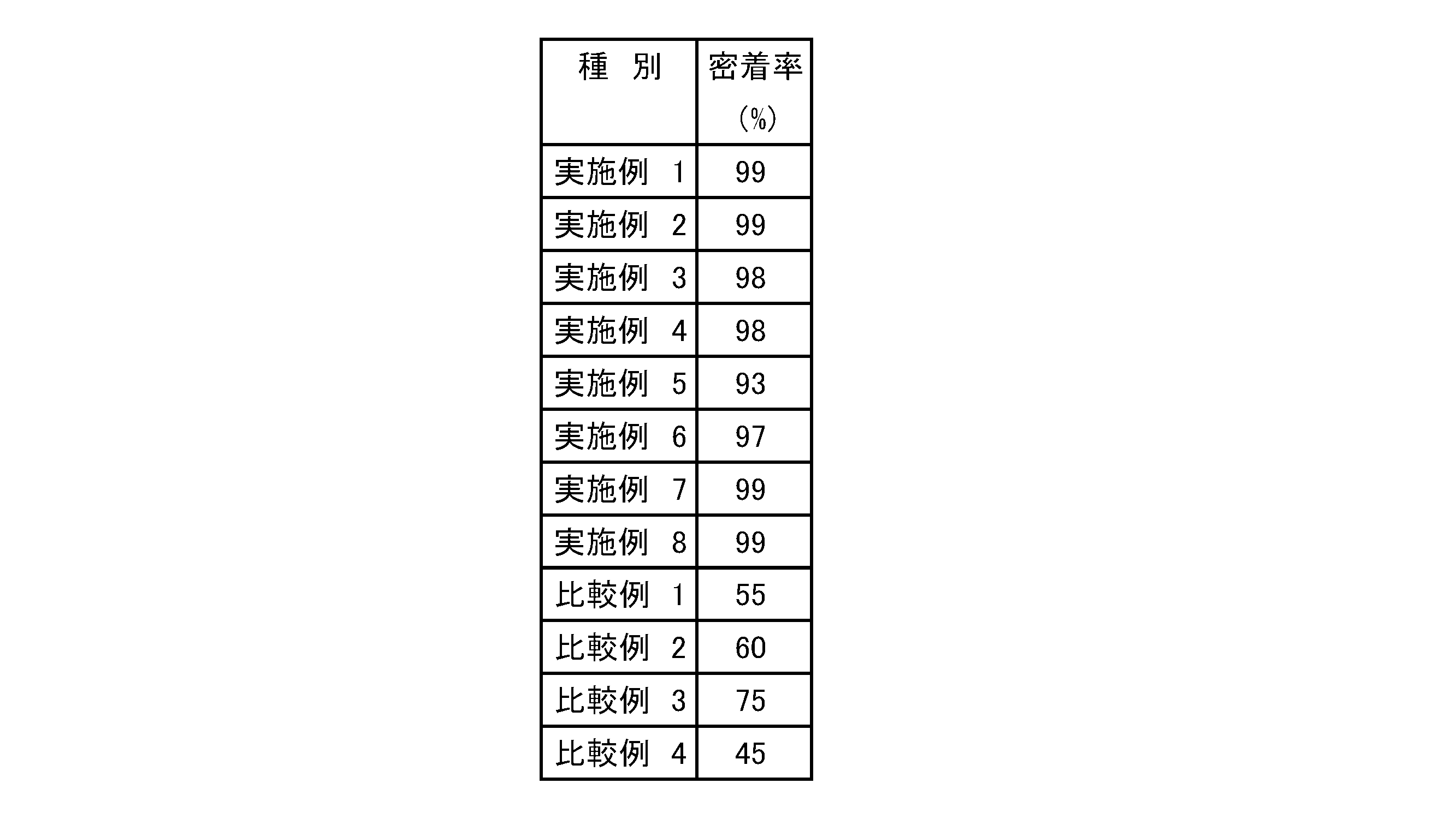
〔実施例9~11〕
比較例1で作製した炭化珪素質複合体を、図3に示すSUS-304製の治具にセットし、M10のネジで主面と垂直な応力を負荷した後、温度500℃の電気炉で30分間加熱したのち、室温まで冷却して負荷を解放した。得られた複合体の反り量を表5に示す。次に、得られた複合体を実施例1~8と同様の方法で評価した結果を表5に示す。表5に示すように、治具を用いて凸面を形成することで密着率を高めることができる。
[Examples 9 to 11]
The silicon carbide composite produced in Comparative Example 1 was set on a jig made of SUS-304 shown in FIG. 3, and a stress perpendicular to the main surface was loaded with an M10 screw, and then an electric furnace at a temperature of 500 ° C. After heating for 30 minutes, the load was released by cooling to room temperature. Table 5 shows the amount of warpage of the obtained composite. Next, Table 5 shows the results of evaluating the obtained composites by the same method as in Examples 1 to 8. As shown in Table 5, the adhesion rate can be increased by forming a convex surface using a jig.

Claims (9)
Priority Applications (4)
| Application Number | Priority Date | Filing Date | Title |
|---|---|---|---|
| US15/115,955 US20170162469A1 (en) | 2014-02-03 | 2015-02-02 | Silicon carbide complex, method for manufacturing same, and heat dissipation component using same |
| CN201580007131.5A CN105981162A (en) | 2014-02-03 | 2015-02-02 | Silicon carbide composite body, manufacturing method thereof, and heat dissipation part using the same |
| JP2015560068A JPWO2015115649A1 (en) | 2014-02-03 | 2015-02-02 | Silicon carbide based composite, method for producing the same, and heat dissipation component using the same |
| EP15743322.8A EP3104406B1 (en) | 2014-02-03 | 2015-02-02 | Power module |
Applications Claiming Priority (2)
| Application Number | Priority Date | Filing Date | Title |
|---|---|---|---|
| JP2014018592 | 2014-02-03 | ||
| JP2014-018592 | 2014-02-03 |
Publications (1)
| Publication Number | Publication Date |
|---|---|
| WO2015115649A1 true WO2015115649A1 (en) | 2015-08-06 |
Family
ID=53757214
Family Applications (1)
| Application Number | Title | Priority Date | Filing Date |
|---|---|---|---|
| PCT/JP2015/052880 Ceased WO2015115649A1 (en) | 2014-02-03 | 2015-02-02 | Silicon carbide complex, method for manufacturing same, and heat dissipation component using same |
Country Status (5)
| Country | Link |
|---|---|
| US (1) | US20170162469A1 (en) |
| EP (1) | EP3104406B1 (en) |
| JP (1) | JPWO2015115649A1 (en) |
| CN (1) | CN105981162A (en) |
| WO (1) | WO2015115649A1 (en) |
Cited By (3)
| Publication number | Priority date | Publication date | Assignee | Title |
|---|---|---|---|---|
| WO2020158775A1 (en) | 2019-01-30 | 2020-08-06 | デンカ株式会社 | Heat-dissipating member and manufacturing method for same |
| WO2020158774A1 (en) | 2019-01-30 | 2020-08-06 | デンカ株式会社 | Heat-dissipating member and manufacturing method for same |
| WO2021200011A1 (en) | 2020-03-31 | 2021-10-07 | デンカ株式会社 | Element-mounted board and method for manufacturingelement-mounted board |
Families Citing this family (3)
| Publication number | Priority date | Publication date | Assignee | Title |
|---|---|---|---|---|
| JP6776953B2 (en) * | 2017-03-07 | 2020-10-28 | 三菱マテリアル株式会社 | Board for power module with heat sink |
| CN108615717A (en) * | 2018-07-20 | 2018-10-02 | 井敏 | A kind of metallized ceramic substrate, method for preparing substrate and substrate and chip welding method |
| CN116393677B (en) * | 2023-04-07 | 2023-11-03 | 哈尔滨工业大学 | Method for preparing diamond/aluminum composite material by high-flux near-net forming |
Citations (5)
| Publication number | Priority date | Publication date | Assignee | Title |
|---|---|---|---|---|
| JPH05507030A (en) | 1990-05-09 | 1993-10-14 | ランキサイド テクノロジー カンパニー,リミティド パートナーシップ | Gate means for manufacturing metal matrix composites |
| JPH09157773A (en) | 1995-10-03 | 1997-06-17 | Hitachi Metals Ltd | Low thermal expansion / high thermal conductivity aluminum composite material and method for producing the same |
| JPH10335538A (en) | 1996-06-14 | 1998-12-18 | Sumitomo Electric Ind Ltd | Semiconductor substrate material, semiconductor substrate, semiconductor device and manufacture thereof |
| JP2000281468A (en) * | 1998-11-12 | 2000-10-10 | Denki Kagaku Kogyo Kk | Silicon carbide composite, method for producing the same, and heat radiation component using the same |
| JP2001291809A (en) * | 2000-04-07 | 2001-10-19 | Denki Kagaku Kogyo Kk | Heat dissipation components |
Family Cites Families (2)
| Publication number | Priority date | Publication date | Assignee | Title |
|---|---|---|---|---|
| JP5144279B2 (en) * | 2006-01-13 | 2013-02-13 | 電気化学工業株式会社 | Aluminum-silicon carbide composite and heat dissipation component using the same |
| CN102815048B (en) * | 2011-06-10 | 2015-01-14 | 比亚迪股份有限公司 | AlSiC composite material, preparation method thereof, and Ni-plated AlSiC composite material |
-
2015
- 2015-02-02 EP EP15743322.8A patent/EP3104406B1/en active Active
- 2015-02-02 US US15/115,955 patent/US20170162469A1/en not_active Abandoned
- 2015-02-02 CN CN201580007131.5A patent/CN105981162A/en active Pending
- 2015-02-02 JP JP2015560068A patent/JPWO2015115649A1/en active Pending
- 2015-02-02 WO PCT/JP2015/052880 patent/WO2015115649A1/en not_active Ceased
Patent Citations (6)
| Publication number | Priority date | Publication date | Assignee | Title |
|---|---|---|---|---|
| JPH05507030A (en) | 1990-05-09 | 1993-10-14 | ランキサイド テクノロジー カンパニー,リミティド パートナーシップ | Gate means for manufacturing metal matrix composites |
| JPH09157773A (en) | 1995-10-03 | 1997-06-17 | Hitachi Metals Ltd | Low thermal expansion / high thermal conductivity aluminum composite material and method for producing the same |
| JPH10335538A (en) | 1996-06-14 | 1998-12-18 | Sumitomo Electric Ind Ltd | Semiconductor substrate material, semiconductor substrate, semiconductor device and manufacture thereof |
| JP2000281468A (en) * | 1998-11-12 | 2000-10-10 | Denki Kagaku Kogyo Kk | Silicon carbide composite, method for producing the same, and heat radiation component using the same |
| JP3468358B2 (en) | 1998-11-12 | 2003-11-17 | 電気化学工業株式会社 | Silicon carbide composite, method for producing the same, and heat radiation component using the same |
| JP2001291809A (en) * | 2000-04-07 | 2001-10-19 | Denki Kagaku Kogyo Kk | Heat dissipation components |
Cited By (10)
| Publication number | Priority date | Publication date | Assignee | Title |
|---|---|---|---|---|
| WO2020158775A1 (en) | 2019-01-30 | 2020-08-06 | デンカ株式会社 | Heat-dissipating member and manufacturing method for same |
| WO2020158774A1 (en) | 2019-01-30 | 2020-08-06 | デンカ株式会社 | Heat-dissipating member and manufacturing method for same |
| CN113474885A (en) * | 2019-01-30 | 2021-10-01 | 电化株式会社 | Heat radiation member and method for manufacturing same |
| CN113474885B (en) * | 2019-01-30 | 2022-07-01 | 电化株式会社 | Heat radiation member and method for manufacturing same |
| CN116086232A (en) * | 2019-01-30 | 2023-05-09 | 电化株式会社 | Heat dissipation member and manufacturing method thereof |
| US12069837B2 (en) | 2019-01-30 | 2024-08-20 | Denka Company Limited | Heat dissipation member and method of manufacturing the same |
| US12213286B2 (en) | 2019-01-30 | 2025-01-28 | Denka Company Limited | Heat dissipation member and method of manufacturing the same |
| CN116086232B (en) * | 2019-01-30 | 2025-10-28 | 电化株式会社 | Heat dissipation component and manufacturing method thereof |
| WO2021200011A1 (en) | 2020-03-31 | 2021-10-07 | デンカ株式会社 | Element-mounted board and method for manufacturingelement-mounted board |
| US12219739B2 (en) | 2020-03-31 | 2025-02-04 | Denka Company Limited | Element-mounted board and method for manufacturing element-mounted board |
Also Published As
| Publication number | Publication date |
|---|---|
| JPWO2015115649A1 (en) | 2017-03-23 |
| EP3104406A1 (en) | 2016-12-14 |
| CN105981162A (en) | 2016-09-28 |
| EP3104406B1 (en) | 2019-04-03 |
| US20170162469A1 (en) | 2017-06-08 |
| EP3104406A4 (en) | 2017-09-13 |
Similar Documents
| Publication | Publication Date | Title |
|---|---|---|
| JP3468358B2 (en) | Silicon carbide composite, method for producing the same, and heat radiation component using the same | |
| JP5144279B2 (en) | Aluminum-silicon carbide composite and heat dissipation component using the same | |
| JP4996600B2 (en) | Aluminum-silicon carbide composite and heat dissipation component using the same | |
| JP4761157B2 (en) | Aluminum-silicon carbide composite | |
| WO2015115649A1 (en) | Silicon carbide complex, method for manufacturing same, and heat dissipation component using same | |
| WO2020013300A1 (en) | Metal-silicon carbide-based composite material, and method for producing metal-silicon carbide-based composite material | |
| CN106796925B (en) | Aluminum-silicon carbide composite and its manufacturing method | |
| JP3907620B2 (en) | Ceramic circuit board integrated aluminum-silicon carbide composite and manufacturing method thereof | |
| JP3792180B2 (en) | Manufacturing method of heat dissipation parts | |
| JP2020012194A (en) | Metal-silicon carbide composite and production method of the same | |
| JP5602566B2 (en) | Heat transfer member made of aluminum-silicon carbide composite | |
| JP2010099686A (en) | Aluminum-silicon carbide composite body and method for producing the same | |
| JP2010042945A (en) | Aluminum-silicon carbide composite and method for producing the same | |
| JP4864593B2 (en) | Method for producing aluminum-silicon carbide composite | |
| JP3913130B2 (en) | Aluminum-silicon carbide plate composite | |
| JP5284704B2 (en) | Aluminum-silicon carbide composite and method for producing the same | |
| JP3737072B2 (en) | Aluminum-silicon carbide composite and method for producing the same | |
| JP4127379B2 (en) | Method for producing aluminum-silicon carbide composite | |
| JP2001291809A (en) | Heat dissipation components | |
| JP3732193B2 (en) | Aluminum-silicon carbide composite and method for producing the same | |
| JPH11157964A (en) | Tabular composite and heat dissipating component using the same | |
| JP2006040992A (en) | Aluminum alloy-silicon carbide composite | |
| JPH11157963A (en) | Tabular composite and heat dissipating component using the same |
Legal Events
| Date | Code | Title | Description |
|---|---|---|---|
| 121 | Ep: the epo has been informed by wipo that ep was designated in this application |
Ref document number: 15743322 Country of ref document: EP Kind code of ref document: A1 |
|
| WWE | Wipo information: entry into national phase |
Ref document number: 15115955 Country of ref document: US |
|
| ENP | Entry into the national phase |
Ref document number: 2015560068 Country of ref document: JP Kind code of ref document: A |
|
| NENP | Non-entry into the national phase |
Ref country code: DE |
|
| REEP | Request for entry into the european phase |
Ref document number: 2015743322 Country of ref document: EP |
|
| WWE | Wipo information: entry into national phase |
Ref document number: 2015743322 Country of ref document: EP |