RU2497175C1 - Flight display system and cognitive flight display for single-rotor helicopter - Google Patents
Flight display system and cognitive flight display for single-rotor helicopter Download PDFInfo
- Publication number
- RU2497175C1 RU2497175C1 RU2012119086/08A RU2012119086A RU2497175C1 RU 2497175 C1 RU2497175 C1 RU 2497175C1 RU 2012119086/08 A RU2012119086/08 A RU 2012119086/08A RU 2012119086 A RU2012119086 A RU 2012119086A RU 2497175 C1 RU2497175 C1 RU 2497175C1
- Authority
- RU
- Russia
- Prior art keywords
- parameters
- helicopter
- flight
- information
- landing
- Prior art date
Links
- 230000001149 cognitive effect Effects 0.000 title claims abstract description 28
- 230000033001 locomotion Effects 0.000 claims abstract description 71
- 230000000007 visual effect Effects 0.000 claims abstract description 63
- 230000001976 improved effect Effects 0.000 claims abstract description 38
- 230000011664 signaling Effects 0.000 claims abstract description 37
- 230000008859 change Effects 0.000 claims abstract description 9
- 230000000694 effects Effects 0.000 claims abstract description 7
- 238000012800 visualization Methods 0.000 claims description 22
- 238000004891 communication Methods 0.000 claims description 16
- 230000009471 action Effects 0.000 claims description 15
- 230000003068 static effect Effects 0.000 claims description 14
- 238000003384 imaging method Methods 0.000 claims description 10
- 230000001939 inductive effect Effects 0.000 claims description 10
- 230000005236 sound signal Effects 0.000 claims description 5
- 238000013507 mapping Methods 0.000 claims description 3
- 230000015654 memory Effects 0.000 claims description 3
- 230000000536 complexating effect Effects 0.000 claims 1
- 238000012876 topography Methods 0.000 claims 1
- 238000005516 engineering process Methods 0.000 abstract description 13
- 239000000126 substance Substances 0.000 abstract 1
- 238000013459 approach Methods 0.000 description 19
- 230000004438 eyesight Effects 0.000 description 17
- 238000000034 method Methods 0.000 description 15
- 230000015572 biosynthetic process Effects 0.000 description 14
- 230000001133 acceleration Effects 0.000 description 11
- 238000009434 installation Methods 0.000 description 10
- 239000000428 dust Substances 0.000 description 8
- 238000000926 separation method Methods 0.000 description 8
- 230000005540 biological transmission Effects 0.000 description 7
- 230000003304 psychophysiological effect Effects 0.000 description 7
- 230000002411 adverse Effects 0.000 description 6
- 230000010006 flight Effects 0.000 description 6
- 239000002689 soil Substances 0.000 description 6
- 230000003287 optical effect Effects 0.000 description 5
- 230000007423 decrease Effects 0.000 description 4
- 230000007787 long-term memory Effects 0.000 description 4
- 238000005259 measurement Methods 0.000 description 4
- 230000008569 process Effects 0.000 description 4
- BXNJHAXVSOCGBA-UHFFFAOYSA-N Harmine Chemical compound N1=CC=C2C3=CC=C(OC)C=C3NC2=C1C BXNJHAXVSOCGBA-UHFFFAOYSA-N 0.000 description 3
- 238000004364 calculation method Methods 0.000 description 3
- 239000011248 coating agent Substances 0.000 description 3
- 238000000576 coating method Methods 0.000 description 3
- 238000012937 correction Methods 0.000 description 3
- 230000007123 defense Effects 0.000 description 3
- 230000006735 deficit Effects 0.000 description 3
- 238000013461 design Methods 0.000 description 3
- 238000011161 development Methods 0.000 description 3
- 238000006073 displacement reaction Methods 0.000 description 3
- 238000009499 grossing Methods 0.000 description 3
- 230000036541 health Effects 0.000 description 3
- 238000012545 processing Methods 0.000 description 3
- 239000004576 sand Substances 0.000 description 3
- 230000001960 triggered effect Effects 0.000 description 3
- 206010069633 Decreased eye contact Diseases 0.000 description 2
- 241000183024 Populus tremula Species 0.000 description 2
- 238000004458 analytical method Methods 0.000 description 2
- 125000004122 cyclic group Chemical group 0.000 description 2
- 230000007812 deficiency Effects 0.000 description 2
- 238000010586 diagram Methods 0.000 description 2
- 230000006870 function Effects 0.000 description 2
- 230000005484 gravity Effects 0.000 description 2
- 230000001965 increasing effect Effects 0.000 description 2
- 230000003993 interaction Effects 0.000 description 2
- 239000003550 marker Substances 0.000 description 2
- 230000003340 mental effect Effects 0.000 description 2
- 239000000203 mixture Substances 0.000 description 2
- 230000004297 night vision Effects 0.000 description 2
- 238000011160 research Methods 0.000 description 2
- 230000004044 response Effects 0.000 description 2
- 230000009897 systematic effect Effects 0.000 description 2
- 238000001931 thermography Methods 0.000 description 2
- XLYOFNOQVPJJNP-UHFFFAOYSA-N water Substances O XLYOFNOQVPJJNP-UHFFFAOYSA-N 0.000 description 2
- ALRKEASEQOCKTJ-UHFFFAOYSA-N 2-[4,7-bis(2-amino-2-oxoethyl)-1,4,7-triazonan-1-yl]acetamide Chemical compound NC(=O)CN1CCN(CC(N)=O)CCN(CC(N)=O)CC1 ALRKEASEQOCKTJ-UHFFFAOYSA-N 0.000 description 1
- 206010000369 Accident Diseases 0.000 description 1
- JFLRKDZMHNBDQS-UCQUSYKYSA-N CC[C@H]1CCC[C@@H]([C@H](C(=O)C2=C[C@H]3[C@@H]4C[C@@H](C[C@H]4C(=C[C@H]3[C@@H]2CC(=O)O1)C)O[C@H]5[C@@H]([C@@H]([C@H]([C@@H](O5)C)OC)OC)OC)C)O[C@H]6CC[C@@H]([C@H](O6)C)N(C)C.CC[C@H]1CCC[C@@H]([C@H](C(=O)C2=C[C@H]3[C@@H]4C[C@@H](C[C@H]4C=C[C@H]3C2CC(=O)O1)O[C@H]5[C@@H]([C@@H]([C@H]([C@@H](O5)C)OC)OC)OC)C)O[C@H]6CC[C@@H]([C@H](O6)C)N(C)C Chemical compound CC[C@H]1CCC[C@@H]([C@H](C(=O)C2=C[C@H]3[C@@H]4C[C@@H](C[C@H]4C(=C[C@H]3[C@@H]2CC(=O)O1)C)O[C@H]5[C@@H]([C@@H]([C@H]([C@@H](O5)C)OC)OC)OC)C)O[C@H]6CC[C@@H]([C@H](O6)C)N(C)C.CC[C@H]1CCC[C@@H]([C@H](C(=O)C2=C[C@H]3[C@@H]4C[C@@H](C[C@H]4C=C[C@H]3C2CC(=O)O1)O[C@H]5[C@@H]([C@@H]([C@H]([C@@H](O5)C)OC)OC)OC)C)O[C@H]6CC[C@@H]([C@H](O6)C)N(C)C JFLRKDZMHNBDQS-UCQUSYKYSA-N 0.000 description 1
- 241000669069 Chrysomphalus aonidum Species 0.000 description 1
- 101000591286 Homo sapiens Myocardin-related transcription factor A Proteins 0.000 description 1
- 101000699762 Homo sapiens RNA 3'-terminal phosphate cyclase Proteins 0.000 description 1
- 102100034099 Myocardin-related transcription factor A Human genes 0.000 description 1
- 101001116283 Phanerodontia chrysosporium Manganese peroxidase H4 Proteins 0.000 description 1
- 101001018261 Protopolybia exigua Mastoparan-1 Proteins 0.000 description 1
- 102100029143 RNA 3'-terminal phosphate cyclase Human genes 0.000 description 1
- IWUCXVSUMQZMFG-AFCXAGJDSA-N Ribavirin Chemical compound N1=C(C(=O)N)N=CN1[C@H]1[C@H](O)[C@H](O)[C@@H](CO)O1 IWUCXVSUMQZMFG-AFCXAGJDSA-N 0.000 description 1
- 230000004931 aggregating effect Effects 0.000 description 1
- 230000002776 aggregation Effects 0.000 description 1
- 238000004220 aggregation Methods 0.000 description 1
- 238000003491 array Methods 0.000 description 1
- 239000011384 asphalt concrete Substances 0.000 description 1
- 230000008901 benefit Effects 0.000 description 1
- 239000003795 chemical substances by application Substances 0.000 description 1
- 230000019771 cognition Effects 0.000 description 1
- 239000003086 colorant Substances 0.000 description 1
- 239000004567 concrete Substances 0.000 description 1
- 238000001514 detection method Methods 0.000 description 1
- 239000006185 dispersion Substances 0.000 description 1
- 230000002349 favourable effect Effects 0.000 description 1
- 230000004907 flux Effects 0.000 description 1
- 239000011521 glass Substances 0.000 description 1
- 230000006698 induction Effects 0.000 description 1
- 230000010354 integration Effects 0.000 description 1
- 239000011159 matrix material Substances 0.000 description 1
- 238000012986 modification Methods 0.000 description 1
- 230000004048 modification Effects 0.000 description 1
- 238000012544 monitoring process Methods 0.000 description 1
- 230000008520 organization Effects 0.000 description 1
- 230000008447 perception Effects 0.000 description 1
- 238000002360 preparation method Methods 0.000 description 1
- 238000012797 qualification Methods 0.000 description 1
- 238000011076 safety test Methods 0.000 description 1
- 239000000725 suspension Substances 0.000 description 1
- 230000001360 synchronised effect Effects 0.000 description 1
- 238000012546 transfer Methods 0.000 description 1
- 230000009466 transformation Effects 0.000 description 1
- 230000001131 transforming effect Effects 0.000 description 1
Images


Landscapes
- Traffic Control Systems (AREA)
- Navigation (AREA)
Abstract
Description
Группа изобретений относится к интегрированным комплексам бортового оборудования вертолета, в частности к системе визуализации полета (далее - СВП), а именно системам визуализации пилотажных параметров полета, системам инструментальной видимости окружающей среды закабинного пространства (организация отображения пространства неба, плоскости подстилающей поверхности и разделяющей их линии), системам отображения препятствий на подстилающей поверхности в реальном режиме времени в зонах взлета и посадки вертолета, системам отображения синтезированной видимости закабинного пространства подстилающей поверхности на этапах набора высоты, горизонтального полета, снижения, захода на посадку до высоты принятия решения, системе улучшенного отображения высотного профиля рельефа местности и предупреждения столкновения вертолета в управляемом полете с земной поверхностью и искусственными препятствиями на ней, а также к когнитивному пилотажному индикатору (далее - КПИ), предназначенному для отображения параметрической и сигнальной информации, характерной для полета одновинтового вертолета.The group of inventions relates to integrated complexes of onboard equipment of a helicopter, in particular to a flight visualization system (hereinafter - SVP), namely visualization systems for flight flight parameters, instrumental systems for visibility of the environment of the cockpit space (organization of the display of the sky space, the plane of the underlying surface and the line separating them ), real-time display systems of obstacles on the underlying surface in helicopter take-off and landing zones, display systems synthesized visibility of the cockpit space of the underlying surface at the stages of climb, horizontal flight, descent, landing to the decision altitude, a system for improved display of the altitude profile of the terrain and for preventing helicopter collisions in controlled flight with the earth's surface and artificial obstacles on it, as well as cognitive flight indicator (hereinafter - KPI), designed to display the parametric and signal information characteristic of a single flight tovogo helicopter.
СВП и КПИ предназначены для безопасного пилотирования вертолета на всех этапах полета (запуск силовых установок и раскрутка трансмиссии, руление, висение, перемещение, взлет, горизонтальный полет, снижение, посадка) и режимах полета (выдерживание заданных скорости, курса, высоты, крена, тангажа, в том числе для выполнения любых режимов маневрирования) в любое время года, в любое время суток, независимо от вида покрытия (бетон, асфальтобетон, грунт, в т.ч. покрытый снегом, песком, влагой, льдом) подстилающей поверхности вертолетной взлетно-посадочной площадки (далее - ВВПП) в различных климатических условиях, в простых и сложных метеорологических условиях, в том числе при визуальной видимости, близкой к нулю.SVP and KPI are intended for safe piloting of a helicopter at all stages of flight (launch of power plants and transmission promotion, taxiing, hovering, moving, take-off, horizontal flight, lowering, landing) and flight modes (maintaining the set speed, course, altitude, roll, pitch , including for performing any maneuvering modes) at any time of the year, at any time of the day, regardless of the type of coating (concrete, asphalt concrete, soil, including covered with snow, sand, moisture, ice) of the underlying surface of the helicopter take-off posa the landing site (hereinafter - VVPP) in various climatic conditions, in simple and complex meteorological conditions, including with visual visibility close to zero.
Заявляемые СВП и КПИ учитывают особенности конструкции и динамики движения вертолета и его управления, специфику его применения как транспортного средства, предназначенного для внеаэродромного использования, и неблагоприятное влияние внешних воздействующих факторов на безопасность полетов вертолетов.The claimed SVP and KPI take into account the design and dynamics of the helicopter and its control, the specifics of its use as a vehicle intended for off-aerodrome use, and the adverse impact of external factors on the safety of helicopter flights.
Предпосылки создания изобретенияBACKGROUND OF THE INVENTION
При летной эксплуатации исправных и управляемых одновинтовых вертолетов возникают проблемы, связанные с обеспечением безопасности полетов из-за непреднамеренного выхода вертолета на границы (за границы) летных эксплуатационных ограничений с последующей потерей управляемости при воздействии на вертолет неблагоприятных внешних возмущений, а также ошибок экипажа в технике пилотирования из-за недостаточности (дефицита) и низкого качества информационного обеспечения экипажа по пилотажным параметрам, а также из-за потери экипажем визуальной видимости окружающей среды закабинного пространства (визуальной видимости земных ориентиров) при попадании вертолета в условия образования снежного/пыльного вихря и/или в сложные метеорологические условия (СМУ).During the flight operation of serviceable and controlled single-rotor helicopters, problems arise in ensuring flight safety due to the unintentional exit of the helicopter at the borders (outside) of flight operational restrictions with the subsequent loss of controllability when the helicopter is exposed to adverse external disturbances, as well as crew errors in piloting technique due to the insufficiency (deficit) and poor quality of the crew information support for flight parameters, as well as due to the loss of a visa by the crew noy visibility environment zakabinnogo space (visual sight terrestrial landmarks) in contact with the helicopter in the formation conditions of the snow / dusty vortex and / or in bad weather (SMU).
С целью выявления причин возникновения авиационных происшествий и серьезных инцидентов (далее - АП и СИ) был проведен анализ состояния безопасности полетов при эксплуатации одновинтовых вертолетов типа Ми-8 и его модификаций, используемых в Гражданской и Государственной авиации (согласно классификации, приведенной в Воздушном Кодексе РФ). За период 2000-2009 гг. выявлено, что наряду с другими причинами возникновения АП и СИ доминирующими являются ошибочные действия экипажей. Анализы причин возникновения АП и СИ показывают, что экипажи не всегда используют имеющиеся резервы вертолета по устойчивости и управляемости для локализации особых ситуаций, возникающих в полете, а также допускают систематические ошибки в технике пилотирования при управлении исправным вертолетом из-за дефицита (недостаточности) и/или низкого качества информационного обеспечения по следующим факторам:In order to identify the causes of aircraft accidents and serious incidents (hereinafter referred to as AP and SI), an analysis was made of the flight safety state during operation of Mi-8 type single-rotor helicopters and its modifications used in Civil and State Aviation (according to the classification given in the Air Code of the Russian Federation ) For the period 2000-2009 it was revealed that along with other causes of AP and SI, the erroneous actions of crews are dominant. Analyzes of the causes of the occurrence of airframes and SI show that crews do not always use the helicopter's available reserves for stability and controllability to localize special situations that arise in flight, and also make systematic errors in the piloting technique when operating a serviceable helicopter due to a shortage (insufficiency) and / or poor quality information support for the following factors:
1. Внешние воздействующие факторы, влияющие на безопасность полетов в силу особенностей конструкции и аэродинамики вертолета, среди которых:1. External factors affecting flight safety due to the design and aerodynamics of the helicopter, including:
- скорость и направление ветра и ее продольная и боковая составляющие на всех этапах полета, особенно при выполнении взлетов и посадок на площадки, подобранные с воздуха, на которых отсутствует метеорологическое обеспечение полетов;- the speed and direction of the wind and its longitudinal and lateral components at all stages of flight, especially when performing takeoffs and landings on sites selected from the air, on which there is no meteorological support for flights;
- техническое состояние ВВПП: продольные и поперечные углы наклона ВВПП, наличие препятствий, прочность грунта, низкая контрастность подстилающей поверхности, а иногда и неизвестное физическое состояние площадки (например, толщина льда, покрытого свежевыпавшим снегом);- the technical condition of the runway: the longitudinal and transverse angles of inclination of the runway, the presence of obstacles, soil strength, low contrast of the underlying surface, and sometimes the unknown physical condition of the site (for example, the thickness of ice covered with fresh snow);
- ошибочное определение экипажем максимально допустимых взлетных/посадочных масс вертолета, зависящих от фактических метеорологических условий (скорости и направления ветра, величины атмосферного давления, температуры наружного воздуха) в местах взлета и посадки из-за отсутствия на борту вертолета соответствующих измерителей;- erroneous determination by the crew of the maximum permissible take-off / landing mass of the helicopter, depending on the actual meteorological conditions (wind speed and direction, atmospheric pressure, outdoor temperature) at the take-off and landing places due to the lack of appropriate meters on board the helicopter;
- отсутствие информационного обеспечения о подвижных и неподвижных препятствиях и расстояния до них, опорах ЛЭП и проводах в зоне взлета и посадки вертолета в СМУ.- lack of information support about moving and stationary obstacles and the distance to them, power transmission towers and wires in the take-off and landing area of the helicopter in SMU.
2. Недостаточность и низкое качество представления экипажу вертолета на индикаторах пилотажных параметров из-за неполного учета аэродинамических особенностей и динамики движения вертолета по следующим параметрам:2. The insufficiency and low quality of the presentation of the helicopter crew on the indicators of aerobatic parameters due to incomplete accounting of the aerodynamic features and dynamics of the helicopter in the following parameters:
- о продольных и поперечных скоростях перемещения вертолета на этапах висения (зависания), перемещения относительно земной/водной поверхности на малых и предельно малых высотах в моменты приземления и отрыва, взлетах и посадках по-вертолетному;- about the longitudinal and transverse speeds of the helicopter moving at the stages of hovering (hovering), movement relative to the earth / water surface at small and extremely low altitudes at the moments of landing and separation, takeoffs and landings by helicopter;
- об угловой скорости вращения - угловой скорости рыскания на всех этапах полета, и особенно в моменты приземления в условиях плохой видимости и образования снежного/пыльного вихря;- about the angular velocity of rotation - the angular velocity of yaw at all stages of flight, and especially at the moments of landing in conditions of poor visibility and the formation of a snow / dusty vortex;
- о малой приборной скорости в зонах взлета, посадки и руления.- low instrument speed in take-off, landing and taxiing zones.
3. Эргономические недостатки представления информации о параметрах положения органов управления вертолетом и их динамики движения, в то время когда эти параметры являются важными пилотажными параметрами и должны постоянно находиться в поле зрения пилотов практически на всех этапах полета, а именно:3. Ergonomic deficiencies in the presentation of information on the parameters of the position of the helicopter controls and their dynamics, while these parameters are important aerobatic parameters and should be constantly in the pilots' field of view at almost all stages of the flight, namely:
- разнесенность (рассредоточенность) по приборной доске (информационному полю дисплея) информации о текущем положении ручки «ШАГ-ГАЗ» (углу установки лопастей несущего винта, далее - НВ), оборотах НВ (частоте вращения НВ), оборотах турбокомпрессоров силовых установок;- diversity (dispersion) on the dashboard (information field of the display) of information on the current position of the STEP-GAS handle (angle of installation of the rotor blades, hereinafter referred to as NV), revolutions of NV (rotational speed of NV), revolutions of turbocompressors of power plants;
- отсутствие информации о темпе (скорости) перемещения ручки «ШАГ-ГАЗ», скорости перекладки педалей управления углами установки лопастей рулевого винта (РВ).- lack of information on the pace (speed) of the "STEP-GAS" handle, the speed of shifting the pedals to control the angles of installation of the tail rotor blades (PB).
4. Отсутствие информационного обеспечения экипажа о характеристиках закабинного пространства (о перемещающейся линии искусственного горизонта, которая по своему положению и перемещению соответствует линии истинного горизонта, видимой членами экипажа из кабины вертолета в простых метеоусловиях) при попадании в условия потери визуального контакта с земными ориентирами и при образовании снежного/пыльного вихря или СМУ.4. Lack of information support for the crew about the characteristics of the outside space (about the moving line of the artificial horizon, which in its position and movement corresponds to the line of the true horizon, visible by crew members from the helicopter cockpit in simple weather conditions) when exposed to conditions of loss of visual contact with landmarks and when the formation of a snow / dusty vortex or SMU.
5. Отсутствие информационного обеспечения экипажа по предотвращению попадания вертолета в режим «вихревое кольцо» в зоне ограничений: приборная скорость-вертикальная скорость снижения-истинная высота полета.5. Lack of information support for the crew to prevent the helicopter from entering the “vortex ring” mode in the restricted area: instrumental speed — vertical speed of descent — true flight altitude.
6. Недостатки в обеспечении экипажа аварийно-предупреждающей сигнальной информацией по следующим параметрам:6. Deficiencies in providing the crew with alarm warning information on the following parameters:
- продольным и поперечным углам наклона ВВПП;- longitudinal and transverse angles of inclination of the runway;
- продольным и поперечным составляющим скорости ветра;- longitudinal and transverse components of wind speed;
- продольным и поперечным скоростям перемещения относительно подстилающей поверхности на малых высотах;- longitudinal and transverse speeds of movement relative to the underlying surface at low altitudes;
- угловой скорости вращения - скорости рыскания;- angular velocity of rotation - yaw rate;
- критическим углам крена, тангажа на малых высотах в моменты приземления, отрыва, руления, перемещениях, зависания, висения;- critical angles of roll, pitch at low altitudes at the moments of landing, separation, taxiing, movements, hovering, hovering;
- превышения максимально допустимых взлетных/посадочных масс в зависимости от фактических метеорологических условий;- exceeding the maximum allowable take-off / landing masses depending on the actual meteorological conditions;
- динамики движения органов управления: отсутствие визуальной, звуковой, тактильной предупреждающей и аварийной сигнальной информации о падении/превышении частоты вращения НВ, темпа перемещения ручки «ШАГ-ГАЗ» и темпа перемещения педалей управления рулевым винтом, установленных эксплуатационными ограничениями;- driving dynamics: lack of visual, audible, tactile warning and emergency alarm information about the fall / excess of the rotational speed of the HB, the speed of movement of the STEP-GAZ handle, and the speed of movement of the pedals of the steering screw set by operational limitations;
- сигнализации о минимально допустимой безопасной высоте полета (далее - МБВ), предназначенной для предотвращения столкновения вертолета с земной поверхностью и искусственными препятствиями на ней в зависимости от характера рельефа подстилающей поверхности (равнинная, холмистая, горная), скорости полета и используемых экипажем правил полета.- alarms about the minimum permissible safe flight altitude (hereinafter - MBV), designed to prevent a helicopter from colliding with the earth's surface and artificial obstacles on it, depending on the nature of the relief of the underlying surface (plain, hilly, mountainous), flight speed and the flight rules used by the crew.
Для предотвращения ошибочных действий экипажа в управляемом полете и повышения уровня безопасности полета, связанных с предотвращением столкновения вертолета с земной поверхностью, препятствиями на ней и возможным опрокидыванием, а также потерей управляемости вертолета, возникает необходимость улучшить существующее информационное обеспечение экипажа, обеспечив его дополнительной параметрической и сигнальной информацией, приведенной в таблице 1.To prevent erroneous actions of the crew in a controlled flight and to increase the level of flight safety associated with preventing a helicopter from colliding with the earth's surface, obstacles on it and possible rollover, as well as loss of helicopter controllability, it becomes necessary to improve the crew’s existing information support by providing it with additional parametric and signal the information given in table 1.
Эта информация должна значительно улучшить визуализацию представления по пилотажно-навигационным параметрам, а также обеспечить экипаж четким и высококачественным интуитивно понятным отображением внешней среды закабинного пространства и препятствий на ней независимо от времени года, суток, фактических метеорологических условий, вида подстилающей поверхности, технических характеристик вида покрытия ВВПП в реальном режиме времени и обеспечить улучшенную инструментальную видимость закабинного пространства на этапах взлета, маневрирования на предельно малых высотах снижения и захода на посадку по-вертолетному и по-самолетному.This information should significantly improve the visualization of the performance by flight and navigation parameters, as well as provide the crew with a clear and high-quality intuitive display of the external environment of the cockpit space and obstacles on it regardless of the time of year, day, actual meteorological conditions, type of underlying surface, technical characteristics of the type of coating Runway in real time and provide improved instrumental visibility of the cockpit space at the take-off stages, maneuver tion at extremely low altitudes decrease and approach in a helicopter and an aircraft.
В связи с этим на индикаторах СВП формат представления (вид отображения) текущего динамического состояния вертолета учитывает особенности конструкции и динамики движения вертолета, неблагоприятное влияние внешних факторов и особенности его управления, летные ограничения по всем этапам и режимам полета. Это позволяет снизить психофизиологическую нагрузку на экипаж, уменьшить умственные усилия, связанные с необходимостью выполнения расчетов в уме при одновременном пилотировании вертолета в быстроменяющейся текущей аэродинамической обстановке, уменьшить время принятия решения по управлению вертолетом за счет применения когнитивных технологий и минимизации зон неопределенностей («зон сомнений»).In this regard, on the SVP indicators, the presentation format (display type) of the current dynamic state of the helicopter takes into account the design features and dynamics of the helicopter, the adverse effects of external factors and its control features, flight restrictions for all stages and flight modes. This allows you to reduce the psychophysiological load on the crew, reduce the mental effort associated with the need to perform calculations in the mind while piloting a helicopter in a rapidly changing current aerodynamic situation, reduce the decision-making time for helicopter control through the use of cognitive technologies and minimize areas of uncertainty (“doubt zones” )


Использованные сокращения на английском языке:Abbreviations used in English:
1. HUD (Head-up display) - пилотажный индикатор на фоне лобового стекла остекления фонаря кабины экипажа.1. HUD (Head-up display) - flight indicator on the background of the windshield glazing of the cockpit lantern.
2. IPFD (Integrated primary flight display) - интегрированный основной пилотажный дисплей2. IPFD (Integrated primary flight display) - integrated primary flight display
3. EFVS (Enhanced Flight Visual System) - система улучшенной инструментальной полетной видимости закабинного пространства3. EFVS (Enhanced Flight Visual System) - the system of improved instrumental flight visibility of the cockpit space
4. CVS (Combine visual system) - система комбинированной видимости, образованной путем наложения на EFVS символьной пилотажной информации4. CVS (Combine visual system) - a system of combined visibility formed by superimposing symbolic flight information on EFVS
5. EGPWS/HTAWS (Enhanced Ground Proximity Warning System/Helicopter Terrain Avoidance Warning System) - улучшенная система предупреждения о близости земли с глобальной базой данных о высотном профиле подстилающей поверхности под вертолетом и в направлении полета.5. EGPWS / HTAWS (Enhanced Ground Proximity Warning System / Helicopter Terrain Avoidance Warning System) - an improved ground proximity warning system with a global database of altitude profiles of the underlying surface under the helicopter and in the direction of flight.
6. SVS (Synthetic Vision System) - система синтезированного видения подстилающей поверхности.6. SVS (Synthetic Vision System) - a system of synthesized vision of the underlying surface.
7. ИЛС - индикатор на фоне лобового стекла остекления кабины пилотов.7. ILS - indicator against the background of the windshield glazing of the cockpit.
8. МФИ - многофункциональный индикатор.8. MFI - multifunctional indicator.
Результаты проведенного анализа состояния безопасности полетов вертолетов свидетельствует о том, что при существующем информационном обеспечении даже квалифицированный экипаж не в состоянии эффективно решать эти задачи и полностью использовать имеющиеся технические возможности вертолетов по управляемости и устойчивости для предотвращения АП и СИ в каждом конкретном полете, особенно в условиях попадания вертолета в СМУ на малых высотах и отсутствия на борту информационного обеспечения экипажа, приведенного в таблице 1.The results of the analysis of the helicopter flight safety state indicate that even with qualified information support, even a qualified crew is not able to efficiently solve these problems and make full use of the helicopter’s technical capabilities for controllability and stability in order to prevent aircraft and SI in each specific flight, especially in conditions helicopter hit the SMU at low altitudes and the absence on board of the crew information support, shown in table 1.
Известны современные интегрированные комплексы бортового оборудования для одновинтовых вертолетов типа Ми-172 - ИБКВ-17 (1/179790.html), _novyie_vertoletyi_mi_na_maks20U.html), интегрированный бортовой комплекс оборудования ИБКО-38 вертолета Ми-38 (разработки компании ЗАО «Транзас», РФ), которые позволили значительно расширить функциональные возможности вертолета, повысить в некоторой степени безопасность полетов, придать кабине экипажа эргономичный и современный вид с применением концепции «стеклянной кабины» компании Honeywell (США).Known modern integrated systems for airborne equipment for single-rotor helicopters of the Mi-172 type - IBKV-17 (1 / 179790.html), _novyie_vertoletyi_mi_na_maks20U.html), an integrated airborne equipment complex IBKO-38 of the Mi-38 helicopter (developed by Transas, Russia ), which made it possible to significantly expand the helicopter's functional capabilities, increase flight safety to some extent, and give the cockpit an ergonomic and modern look using the “glass cockpit” concept of Honeywell (USA).
Комплекс ИБКВ-17 обеспечивает пилотирование и навигацию вертолета днем и ночью в простых и сложных метеоусловиях экипажем, состоящим из двух пилотов, инструментальный заход на посадку (при установке дополнительного оборудования - по II категории ИКАО), заход на посадку по сигналам GPS/ГЛОНАСС, автоматический контроль работы вертолетного оборудования. Дублированная вычислительная система вертолетовождения обеспечивает непрерывное счисление текущих координат места вертолета и коррекцию по данным автономных средств навигации (автоматическую или по команде экипажа).The IBKV-17 complex provides piloting and navigation of a helicopter day and night in simple and difficult weather conditions by a crew of two pilots, instrumental approach approach (when installing additional equipment - according to ICAO category II), approach approach by GPS / GLONASS signals, automatic control of the operation of helicopter equipment. The duplicated helicopter computing system provides continuous calculation of the current coordinates of the helicopter's location and correction according to the data of autonomous navigation aids (automatic or by crew command).
Навигационная информация наложена на подвижную карту, на которую выводится изображение подстилающей поверхности, формируемое системой раннего предупреждения приближения к земле, и изображение от метеолокатора. Дополнительно может выводиться изображение от различных оптических систем и видеокамер, установленных на борту.Navigation information is superimposed on a moving map, which displays the image of the underlying surface, formed by the early warning system of approaching the ground, and the image from the weather radar. Additionally, an image from various optical systems and video cameras installed on board can be displayed.
Повышение безопасности полета обеспечивается при помощи современных средств навигации, посадки и связи, гарантируется безопасность маловысотного полета за счет применения системы раннего предупреждения приближения к земле. Кроме того, комплекс адаптирован для работы с очками ночного видения.Improving flight safety is ensured by using modern means of navigation, landing and communication; the safety of low-altitude flights is guaranteed through the use of an early warning system of approaching the ground. In addition, the complex is adapted for working with night vision goggles.
Однако недостатками вышеназванных интегрированных комплексов являются ограниченный объем информации, предоставляемой экипажу для безопасного пилотирования вертолета на всех этапах и режимах полета, связанный с неполным учетом аэродинамических особенностей и особенностей управления вертолетом, влияния внешних воздействующих факторов на безопасность полетов, особенно это касается выполнения взлетов и посадок в условиях образования пыльного/снежного вихря, отсутствие информации о фактических метеорологический условиях в местах взлета и посадки, и, особенно, неизвестного воздействия ветра и недостоверной информации о техническом состоянии вертолетных взлетно-посадочных площадок, в частности фактических продольных и поперечных углов наклона подстилающей поверхности, наличия препятствий на ней. Т.е. отсутствует информационное обеспечение экипажа по разделам 2, 3, 4 таблицы 1, отсутствует аварийно-предупреждающая сигнальная информация на малых и предельно малых высотах, связанная с особенностями динамики полета вертолета (частично имеется информация по пп.1.2 и 1.3).However, the disadvantages of the above integrated systems are the limited amount of information provided to the crew for the safe piloting of the helicopter at all stages and flight modes, associated with incomplete consideration of the aerodynamic and helicopter control features, the influence of external factors on flight safety, especially with regard to takeoffs and landings in formation conditions of a dusty / snow vortex; lack of information on actual meteorological conditions at summer and landing, and, especially, the unknown impact of the wind and inaccurate information about the technical condition of helicopter landing sites, in particular the actual longitudinal and transverse angles of inclination of the underlying surface, the presence of obstacles on it. Those. there is no information support for the crew in
В настоящее время известен ряд иностранных аэрокосмических компаний, занимающихся разработкой новых технологий, которые предназначены для обеспечения взлета и посадки воздушных судов в крайне неблагоприятных метеорологических условиях, например в условиях низкой облачности и видимости менее 30 метров.Currently, a number of foreign aerospace companies are known that are developing new technologies that are designed to provide takeoff and landing of aircraft in extremely adverse weather conditions, for example, in conditions of low cloud cover and visibility of less than 30 meters.
США, Великобритания, Франция и Германия активно участвуют в попытках решить проблему обеспечения безопасности полетов вертолетов. Однако на сегодняшний день готовых решений не найдено (www, aviationtoday. com/regions/usa).The United States, Britain, France and Germany are actively participating in attempts to solve the problem of ensuring the safety of helicopter flights. However, no ready-made solutions have been found to date (www, aviationtoday.com/regions/usa).
Лидерами в этой области являются Sikorsky Aircraft Corp. (США), Rockwell Collins Inc. (США), Gulfstream Aerospace Corporation (США), Honeywell International (США), Garmin (США), Aspen Avionics (США), Eads Deutschland GmbH (Германия), Thales (Франция) и ряд других.The leaders in this area are Sikorsky Aircraft Corp. (USA), Rockwell Collins Inc. (USA), Gulfstream Aerospace Corporation (USA), Honeywell International (USA), Garmin (USA), Aspen Avionics (USA), Eads Deutschland GmbH (Germany), Thales (France) and several others.
Аэрокосмическая компания Honeywell International разработала новую технологию для самолетов под названием Enhanced Flight Visual System / Synthetic Vision System (EFVS/SVS) - система улучшенной инструментальной полетной видимости закабинного пространства/система синтезированного видения подстилающей поверхности. Система SVS представляет экипажу базу данных и графическую 3D-визуализацию маршрутов воздушных судов, показывая на индикаторе в схематическом виде поверхность земли, над которой летит воздушное судно, и возможные препятствия на ней.The aerospace company Honeywell International has developed a new technology for aircraft called the Enhanced Flight Visual System / Synthetic Vision System (EFVS / SVS) - an enhanced instrumented cabin visibility / synthesized vision system for the underlying surface. The SVS system provides the crew with a database and graphical 3D visualization of aircraft routes, showing on the indicator in a schematic form the surface of the earth over which the aircraft is flying and possible obstacles on it.
Новая система EFVS работает с инфракрасными сенсорами, установленными на «носу» самолета, и получает реальные данные отображения земной поверхности, «накладывая» их на данные SVS. Совместно два массива данных позволяют экипажу наблюдать местность в зоне взлета и посадки воздушного судна, как в «ясный день». Отображение информации осуществляется на пилотажных дисплеях Honeywell (IPED), представляющих собой ЖК-экраны, установленные на приборной панели в кабине пилота. Система EFVS/SVS используется на воздушных судах типа Gulfstream. В настоящее время система EFVS тестируется на вертолетах. Несмотря на решение одной из главных проблем вертолета - обеспечения экипажа улучшенной инструментальной (приборной) видимостью закабинного пространства подстилающей поверхности в зонах взлета и посадки вертолета, вышеназванная система не решает задачу по обеспечению безопасности полетов вертолетов в комплексе, как показано в таблице 1 в пп.1, 2, 3 из-за ограниченного объема выдачи информации, необходимой экипажу для обеспечения безопасности полета на всех его этапах и режимах.The new EFVS system works with infrared sensors mounted on the "nose" of the aircraft, and receives real earth surface display data, "superimposing" them on the SVS data. Together, two data arrays allow the crew to observe the terrain in the take-off and landing area of the aircraft, as on a “clear day”. Information is displayed on Honeywell aerobatic displays (IPED), which are LCD screens mounted on the dashboard in the cockpit. The EFVS / SVS system is used on Gulfstream aircraft. Currently, the EFVS system is being tested on helicopters. Despite the solution of one of the main problems of the helicopter - providing the crew with improved instrumental (instrument) visibility of the cockpit space of the underlying surface in the take-off and landing areas of the helicopter, the above system does not solve the problem of ensuring the safety of helicopter flights in the complex, as shown in table 1 in
Известно, что фирма Honeywell International совместно с другими американскими фирмами - Sikorsky Aircraft Corp., Sierra Nevada Corp. работает над новой системой посадки вертолетов - «Sandblaster», предназначенной для обеспечения безопасности полетов в условиях образования пыльного/снежного вихря при нулевой видимости и/или отсутствии у экипажа достоверных сведений о местности в районе посадки, с использованием миллиметрового радара (ММ3) и лазерного радара (LADAR). В системе использованы современные технологии визуализации закабинного пространства подстилающей поверхности, датчики, которой «видят» земную поверхность сквозь облако пыли, системы синтетического видения и совместной обработки данных. Нажатием одной кнопки приводится в действие автоматическая система управления вертолетом (разработка Sikorsky Aircraft Corp.), которая переводит его из режима полета в режим висения на низкой высоте над заранее заданной посадочной площадкой практически без смещения. В процессе приближения к земле трехмерный радар (разработка Sierra Nevada Corp.), действие которого возможно сквозь песок и пыль, обнаруживает препятствия и объекты, находящиеся в зоне посадки. На бортовой индикатор выводятся трехмерное изображение зоны посадки и окружающая ее местность, полученное от радара, датчика локального наружного наблюдения (SLEEK - разработка Honeywell International) и системы синтезированного видения подстилающей поверхности (SVS). Система позволяет обнаруживать препятствия и объекты в районе приземления в пределах 360°.It is known that Honeywell International, together with other American firms - Sikorsky Aircraft Corp., Sierra Nevada Corp. working on a new helicopter landing system - Sandblaster, designed to ensure flight safety in the conditions of formation of a dusty / snow whirlwind with zero visibility and / or lack of reliable crew information about the terrain in the landing area using a millimeter radar (MM3) and a laser radar (LADAR). The system uses modern technologies for visualizing the camber space of the underlying surface, sensors that “see” the earth's surface through a cloud of dust, synthetic vision systems and joint data processing. At the touch of a button, an automatic helicopter control system (developed by Sikorsky Aircraft Corp.) is activated, which transfers it from flight mode to hover mode at low altitude above a predetermined landing site with virtually no displacement. In the process of approaching the ground, a three-dimensional radar (developed by Sierra Nevada Corp.), the action of which is possible through sand and dust, detects obstacles and objects located in the landing zone. The on-board indicator displays a three-dimensional image of the landing zone and its surroundings, obtained from the radar, a local outdoor observation sensor (SLEEK - developed by Honeywell International) and a synthetic surface vision system (SVS). The system allows you to detect obstacles and objects in the landing area within 360 °.
Испытания системы безопасности на вертолете BLACK HAWK в январе 2009 г. показали, что экипаж может безопасно посадить вертолет на площадку со множеством опасных препятствий и имеющую к тому же уклон. [110VgnVCM1000004f62529fRCRD]. Однако необходимо иметь в виду и то, чтобы обеспечить полную безопасность в управляемом полете, необходимо дополнительно решить и задачи, показанные в таблице 1 пп.1, 2, 3.Safety tests on a BLACK HAWK helicopter in January 2009 showed that the crew can safely land the helicopter on a site with many dangerous obstacles and also having a slope. [110VgnVCM1000004f62529fRCRD]. However, it is necessary to keep in mind that in order to ensure complete safety in a controlled flight, it is also necessary to solve the tasks shown in Table 1,
В настоящее время фирма Sikorsky Aircraft Corp. ведет работы по контракту с DARPA {Defense Advanced Research Projects Agency - агентство передовых оборонных исследовательских проектов - Министерства обороны США) новой системы посадки для вертолетов «Sandblaster», предназначенной для отображения окружающей среды, используя 94 ГГц радар, который позволяет пилоту видеть земную поверхность «сквозь» облако ().Currently, Sikorsky Aircraft Corp. works under a contract with DARPA (Defense Advanced Research Projects Agency - an agency of advanced defense research projects - the US Department of Defense) of the new landing system for helicopters Sandblaster, designed to display the environment using a 94 GHz radar that allows the pilot to see the earth’s surface through the cloud ().
Разработка систем инструментальной видимости закабинного пространства, функционирующих в реальном режиме времени, и синтезированной видимости закабинного пространства ведутся в соотв етствии с требованиями стандарта США RTCA DO-315 «Minimum Aviation System Performance Standard (MASPS) for Enhanced Vision Systems (EVS), Synthetic Vision Systems (SVS), Combine Vision Systems (CVS) and Enhanced Flight Vision Systems (EFVS)».The development of real-time instrumented visibility of the outside space and the synthesized visibility of the inside space is carried out in accordance with the requirements of the US standard RTCA DO-315 "Minimum Aviation System Performance Standard (MASPS) for Enhanced Vision Systems (EVS), Synthetic Vision Systems (SVS), Combine Vision Systems (CVS) and Enhanced Flight Vision Systems (EFVS). ”
Программа, аналогичная американской «Sandblaster», существует в Великобритании под названием «LVL» (Low-Visibility Landing - посадка при низкой видимости) - (09/sandblaster-and-lvl-clear-air).A program similar to the American Sandblaster exists in the UK under the name LVL (Low-Visibility Landing - low-visibility landing) - (09 / sandblaster-and-lvl-clear-air).
В рамках работы над «LVL» разработчики пытаются найти решение, которое бы позволило пилоту иметь визуальную информацию о технических характеристиках зоны приземления и которая бы отражалась на лобовом стекле или в виде нашлемной индикации. «LVL» так же, как и система «Sandblaster», базируется на технологии совместной обработки данных (от LADAR, инфракрасного и миллиметрового радаров), наложенных на базу данных о рельефе местности. В данной работе принимает участие компания Atlantic Inertial Systems - AIS (ранее BAE Systems Inertial Products) - разработчик системы TERPROM - системы обнаружения препятствий.As part of the work on “LVL”, developers are trying to find a solution that would allow the pilot to have visual information about the technical characteristics of the touchdown zone and which would be reflected on the windshield or in the form of a helmet-mounted display. “LVL”, like the Sandblaster system, is based on joint data processing technology (from LADAR, infrared and millimeter radars) superimposed on a terrain database. Atlantic Inertial Systems - AIS (formerly BAE Systems Inertial Products) - the developer of the TERPROM - obstacle detection system, takes part in this work.
Система «LVL» должна обеспечить данные о точном положении вертолета по отношению к препятствию, а также устранения ошибок в картах. Она может работать в отсутствии GPS. Интегрируя данные о препятствиях с данными активных датчиков, получают полную картину зоны приземления в реальном времени непосредственно до входа вертолета в облако пыли.The LVL system should provide data on the exact position of the helicopter in relation to the obstacle, as well as eliminate errors in the maps. It can work in the absence of GPS. By integrating obstacle data with active sensor data, you get a complete picture of the real-time landing zone immediately before the helicopter enters the dust cloud.
Однако так же, как и описанные выше системы, «LVL» не решает проблемы обеспечения безопасности полетов, связанные с внешними воздействующими факторами на вертолет (влияние ветра, углов наклона взлетно-посадочных площадок, дополнительная просадка пневматиков шасси в малопрочный грунт), с особенностями управления вертолетом (темп перемещения рычага управления углами установки лопастей НВ, темп перемещения педалей управления углами установки РВ, падение или превышение частоты вращения НВ) и эргономическими недостатками по представлению экипажу параметрической и сигнальной информации, необходимой экипажу для безопасного пилотирования. Т.е. успешно решаются только проблемы, приведенные в п.4 таблицы 1.However, just like the systems described above, “LVL” does not solve the flight safety problems associated with external factors affecting the helicopter (the influence of wind, tilt angles of runways, additional landing gear pneumatics in low-strength soil), with control features by helicopter (pace of movement of the control lever for the installation angles of HB blades, pace of movement of the pedals of control of the angles of the installation of HBs, fall or excess of the rotation speed of HBs) and ergonomic imperfections in the presentation of e ipazhu parametric and signaling information necessary for the safe carriage of piloting. Those. only the problems given in
Известен патент США №7642929, G01C 23/00, опубл. 05.01.2010, в котором раскрывается система информационной поддержки экипажа при посадке вертолета. Своим возникновением она обязана военным операциям в Ираке, Саудовской Аравии и Афганистане. Во время посадки вертолет поднимал облако пыли и песка высотой до 100 футов так, что площадка для приземления скрывалась из виду. В соответствии с формулой изобретения вертолет оснащен камерами (например, инфракрасной камерой) и датчиками, которые выявляют наличие препятствий на площадке для предотвращения столкновения с ними при приземлении до того, как образуется облако пыли. В качестве датчика используют камеру ночного видения или электронный радар (либо LADAR). Сигналы с датчиков поступают в память компьютера. Имеется также инерциальная навигационная система, обрабатывающая выходные сигналы системы управления вертолетом. Это могут быть сигналы крена, тангажа, рысканья, а также информация о высоте и скорости вертолета. Имеется возможность получить 3-мерное изображение окружающего ландшафта при приземлении. Данные отображаются на обычном экране катодной трубки, либо на индикаторах на лобовом стекле, либо на нашлемных индикаторах. Благодаря целому ряду алгоритмов формируется изображение в реальном масштабе времени. Однако данная система также имеет ряд недостатков в информационном обеспечении, среди которых отсутствие информации:Known US patent No. 7642929, G01C 23/00, publ. 01/05/2010, which discloses a crew information support system for helicopter landing. It owes its origin to military operations in Iraq, Saudi Arabia and Afghanistan. During landing, the helicopter raised a cloud of dust and sand up to 100 feet high so that the landing area was hidden from view. In accordance with the claims, the helicopter is equipped with cameras (for example, an infrared camera) and sensors that detect the presence of obstacles on the site to prevent collision with them when landing before a dust cloud forms. As a sensor, a night vision camera or electronic radar (or LADAR) is used. Signals from the sensors enter the computer's memory. There is also an inertial navigation system that processes the output signals of the helicopter control system. It can be signals of roll, pitch, yaw, as well as information about the height and speed of the helicopter. It is possible to get a 3-dimensional image of the surrounding landscape upon landing. Data is displayed on a conventional cathode tube screen, or on indicators on the windshield, or on helmet-mounted indicators. Thanks to a number of algorithms, an image in real time is formed. However, this system also has a number of shortcomings in information support, including a lack of information:
- о скорости и направлении ветра на всех этапах полета, и особенно на этапах взлета и посадки по-вертолетному;- about the speed and direction of the wind at all stages of flight, and especially at the stages of take-off and landing in a helicopter;
- о максимально допустимых взлетных/посадочных массах, зависящих от фактических метеорологических условий в месте взлета и посадки вертолета;- on the maximum allowable take-off / landing masses, depending on the actual meteorological conditions at the place of take-off and landing of the helicopter;
- об особенностях управления вертолетом (темп управления общим шагом НВ, темпам перекладки педалей управления РВ);- about the features of controlling the helicopter (the rate of control of the general step of the HB, the pace of shifting the pedals of the control of the PB);
- о сигнальной информации по падению и превышению частоты вращения НВ установленных эксплуатационных ограничений, о продольной и поперечной скоростях перемещения вертолета на малых и предельно малых высотах.- on signaling information on the fall and excess of the rotational speed of the HB of the established operational limitations, on the longitudinal and transverse speeds of the helicopter at small and extremely low altitudes.
Т.е. отсутствует информация по пп.1.1, т.к. точность определения углов наклона ВВПП в этом патенте превышает 10°, что не удовлетворяет требованиям безопасного приземления вертолета (которые составляют 3°), а также отсутствует информационное обеспечение по пп.1.6, 2.1, 2.2, 2.3, 3.1, 3.2, 3.3, 3.4, приведенных в таблице 1.Those. there is no information according to paragraph 1.1, because the accuracy of determining the inclination angles of the runway in this patent exceeds 10 °, which does not meet the requirements for safe landing of the helicopter (which are 3 °), and there is no information support according to paragraphs 1.6, 2.1, 2.2, 2.3, 3.1, 3.2, 3.3, 3.4, given in table 1.
Известен также патент США №7091881, G01C 21/00, опубл. 15.08.2006, в котором описаны вертолетные средства, предназначенные для безопасного приземления в условиях образования пыльного/снежного вихря и низкой видимости, которые используют отображения окружающего пространства и данные о динамике движения вертолета, полученные с помощью различных датчиков первичной информации, которые непрерывно обновляются и представляются экипажу через шину данных. В этом же патенте представлена интегрированная дисплейная система, включающая основной пилотажный дисплей и дисплей висения, которые используются в условиях плохой видимости. Дисплей висения может также содержать индикатор истинной высоты, замеренной радаром, символы отклонения от заданного курса и символы бокового смещения, что позволяет летчикам обнаружить отклонение от курса, которое часто имеет место в условиях плохой видимости. Данный дисплей обеспечивает летчика информацией о текущем значении высоты над землей и имеет сигнализацию об опасной скорости сближения вертолета с препятствиями на земной поверхности. Например, ленточный индикатор снижения может иметь зеленый фон, если скорость сближения с землей в пределах нормы, желтый фон, если значения приближаются к критическим, красный, если значения вышли за критические режимы. Дисплей висения включает систему отображения отклонения вертолета от заданного курса, индикатор бокового и продольного перемещения вертолета в режиме висения.Also known US patent No. 7091881,
Недостатком данных технических решений является то, что вертолетная интегрированная дисплейная система может использоваться в СМУ в режиме висения для балансировки вертолета, но не обеспечивает экипаж вертолета визуальным контактом с земными ориентирами, а также полными пилотажными параметрами, необходимыми для безопасной эксплуатации вертолета. Т.е. отсутствует информационное обеспечение по пп.1.1; 1.6; 2.1; 2.2; 2.3; 3.1; 3.3; 3.4; 4.1; 4.2, приведенным в таблице 1.The disadvantage of these technical solutions is that the helicopter integrated display system can be used in SMU in the hover mode for balancing the helicopter, but it does not provide the helicopter crew with visual contact with landmarks, as well as the full flight parameters necessary for the safe operation of the helicopter. Those. no information support according to paragraph 1.1; 1.6; 2.1; 2.2; 2.3; 3.1; 3.3; 3.4; 4.1; 4.2 shown in table 1.
Известен патент EP №1906151, G01C 23/00, опубл. 02.04.2008, в котором предложен индикатор для отображения посадочной площадки, где с высоким разрешением показана площадка до того момента, когда вертолет создает пыльный/снежный вихрь во время посадки. Для этого используется инерциальная навигационная система (либо отдельная система). При этом согласно изобретению изображение трансформируется для отображения с нужной точки обзора, при этом оно накладывается на текущее положение вертолета по отношению к посадочной площадке. К тому же на индикаторе отражаются препятствия, находящиеся в зоне посадки. Таким образом, система значительно улучшает ориентацию летчика, обеспечивая безопасную посадку даже при нулевой видимости. В основе изобретения лежит узел обработки (например, компьютер). Имеются также другие логические цепи. В компьютер из навигационной системы, которая оснащена приемником GPS, поступает информация о текущем местоположении вертолета. Может быть использована и автономная навигационная система вертолета. Дополнительная информация может быть получена из навигационной базы самого вертолета, которая включает полетное задание, координаты заданного места посадки и профиль местности с препятствиями. Эта система позволяет точно сориентировать в нужном направлении датчик цифрового изображения (например, цифровую камеру), смонтированный на рамке. С камерой синхронизирован импульсный источник света. Как правило, по мере приближения к земле производится ряд снимков до потери визуальной видимости подстилающей поверхности из-за попадания вертолета в зону снежного/пыльного вихря, которые в последующем используются для приземления вертолета в условиях отсутствия видимости земной поверхности.Known patent EP No. 1906151, G01C 23/00, publ. 04/02/2008, in which an indicator is proposed for displaying the landing site, where the landing area is shown with high resolution until the moment when the helicopter creates a dusty / snow whirlwind during landing. For this, an inertial navigation system (or a separate system) is used. Moreover, according to the invention, the image is transformed for display from the desired point of view, while it is superimposed on the current position of the helicopter with respect to the landing site. In addition, the indicator reflects obstacles in the landing zone. Thus, the system significantly improves the orientation of the pilot, ensuring a safe landing even with zero visibility. The invention is based on a processing unit (for example, a computer). Other logic circuits are also available. The computer from the navigation system, which is equipped with a GPS receiver, receives information about the current location of the helicopter. An autonomous helicopter navigation system can also be used. Additional information can be obtained from the navigation base of the helicopter itself, which includes the flight mission, the coordinates of the given landing site and the terrain profile with obstacles. This system allows you to accurately orient in the right direction the digital image sensor (for example, a digital camera) mounted on the frame. A pulsed light source is synchronized with the camera. As a rule, when approaching the ground, a series of images are taken until the visual visibility of the underlying surface is lost due to the helicopter entering the snow / dust vortex zone, which are subsequently used for helicopter landing in the absence of visibility of the earth's surface.
Один или более лазерных дальномеров центрированы с камерой и предоставляют информацию о степени наклона посадочной площадки. В это время дополнительный лазерный дальномер, направленный вниз, или радарный высотомер предоставляют информацию о расстоянии до земли. Множество лазерных дальномеров или прожектор помогают выявить наклон поверхности. Используется также РЛС миллиметрового диапазона, которая на определенной частоте может «видеть сквозь» облако пыли в реальном времени, или инфракрасный радар (FLIR), направленный вперед, который может отобразить подстилающую поверхность без использования РЛС. Полученное изображение поступает на процессор, который делает изображение более четким благодаря 3D графике, накладывая на него либо в виде текста, либо в виде графики информацию о текущем положении вертолета по отношению к посадочной площадке. При этом это изображение можно показать с любой точки обзора на индикаторе. Однако вышеназванная система не может обеспечить полную безопасность полета вертолета при выполнении полетов на площадки, подобранные с воздуха, поскольку в базе данных вертолетного компьютера отсутствует информационное обеспечение по характеристикам рельефа местности предполагаемого места приземления вертолета. Также система не учитывает влияния на вертолет внешних воздействующих факторов:One or more laser rangefinders are centered with the camera and provide information about the degree of inclination of the landing site. At this time, an optional downward laser rangefinder or radar altimeter provides information about the distance to the ground. Many laser rangefinders or spotlights help detect surface tilt. A millimeter range radar is also used, which at a certain frequency can “see through” a dust cloud in real time, or a forward-facing infrared radar (FLIR) that can display the underlying surface without using a radar. The resulting image is sent to the processor, which makes the image clearer thanks to 3D graphics, superimposing on it either in the form of text or in the form of graphics information about the current position of the helicopter in relation to the landing site. At the same time, this image can be shown from any point of view on the indicator. However, the above system cannot ensure the complete safety of a helicopter’s flight when flying to sites selected from the air, since the helicopter computer database does not have information support on the terrain characteristics of the proposed helicopter landing site. Also, the system does not take into account the influence of external factors on the helicopter:
- метеорологических условий в зоне приземления и взлета, в частности отсутствует информационное обеспечение экипажа о скорости и направлении ветра, температуре наружного воздуха и величине атмосферного давления, которые непосредственно влияют на безопасность полета вертолета;- meteorological conditions in the landing and take-off zone, in particular, there is no information support for the crew about wind speed and direction, outside temperature and atmospheric pressure, which directly affect the helicopter flight safety;
- технических характеристик взлетно-посадочной площадки (продольные и поперечные углы наклона, плотность грунта, возможность просадки пневматиков колес стоек шасси вертолета в малопрочный грунт), которые могут привести к опрокидыванию вертолета;- technical characteristics of the runway (longitudinal and transverse tilt angles, soil density, the possibility of pneumatics of the wheels of the landing gears of the helicopter landing in low-strength soil), which can lead to a rollover of the helicopter;
- максимально допустимых взлетных/ посадочных масс в месте взлета и посадки, зависящих от фактических метеорологических условий полета;- the maximum allowable take-off / landing masses at the take-off and landing site, depending on the actual meteorological conditions of the flight;
- особенности динамики полета вертолета, связанные с управлением вертолетом, в частности отсутствует информационное обеспечение по темпу перемещения управления общим шагом НВ.- features of the dynamics of the flight of the helicopter associated with the control of the helicopter, in particular, there is no information support on the rate of movement of the control of the general step of the HB.
Наиболее близким аналогом по своей сущности к вертолетным средствам визуализации полета (СВП), предназначенным для повышения уровня безопасности полетов, являются известные средства, показанные в заявке США на изобретение №2010073198, G08B 21/00, опубл. 25.03.2010. В ней описаны человеко-машинный интерфейс, предназначенный для предотвращения столкновения вертолета с подстилающей поверхностью и препятствиями на ней, а также потери управляемости вертолета в СМУ в зоне взлета и посадки. Данный интерфейс описывает средства получения отображения подстилающей поверхности, на которые дополнительно накладывается символьное отображение параметрической информации, необходимое для безопасного пилотирования вертолета, а именно:The closest analogue in essence to helicopter flight visualization equipment (SVP), designed to increase the level of flight safety, are the known means shown in US application for invention No.2010073198,
- высота над землей;- height above the ground;
- координаты пространственного положения вертолета: углы крена, тангажа и курса;- coordinates of the spatial position of the helicopter: roll, pitch and course angles;
- путевая скорость;- ground speed;
- вертикальная скорость;- vertical speed;
- угловая скорость вращения;- angular velocity of rotation;
- информация о наличии препятствий в зоне приземления;- information on the presence of obstacles in the touchdown zone;
- координаты места приземления, которые были заранее выбраны при подготовке к полету;- coordinates of the landing site, which were pre-selected in preparation for the flight;
- текущее удаление до места приземления.- current removal to the place of landing.
Визуализация отображения места приземления (инструментальная видимость закабинного пространства), на которое накладывается параметрическая пилотажная информация, значительно снижает психофизиологическую нагрузку на экипаж, создавая благоприятные условия для пилотирования вертолета, которые интуитивно напоминают экипажу визуальные условия захода на посадку.Visualization of the display of the landing site (instrumental visibility of the cockpit space), on which parametric flight information is superimposed, significantly reduces the psychophysiological load on the crew, creating favorable conditions for helicopter piloting, which intuitively remind the crew of the visual landing conditions.
При этом формируется виртуальная плоскость истинного горизонта, на которую накладывают виртуальный рельеф местности в зоне приземления вертолета. Причем плоскость истинного горизонта постоянно обновляется в зависимости от высоты полета вертолета. Отображение рельефа местности может быть выполнено в 3D проекции. Для формирования подобного отображения полетной информации в зоне приземления при отсутствии визуальной видимости земных ориентиров используется множество датчиков первичной информации. Среди них - измерители истинной высоты полета, путевой скорости, параметров пространственного положения вертолета и средства получения отображения земной поверхности в зоне приземления: радары, LADARS, телевизионные и тепловизионные камеры, которые позволяют получить отображение земной поверхности даже в условиях отсутствия визуальной видимости подстилающей поверхности.In this case, a virtual plane of the true horizon is formed, on which a virtual terrain is imposed in the helicopter landing zone. Moreover, the plane of the true horizon is constantly updated depending on the height of the helicopter. Terrain mapping can be performed in 3D projection. For the formation of such a display of flight information in the touchdown zone in the absence of visual visibility of landmarks, many primary information sensors are used. Among them are meters of the true flight altitude, ground speed, helicopter spatial position parameters, and means of obtaining the display of the earth's surface in the landing zone: radars, LADARS, television and thermal imaging cameras that can display the earth's surface even in the absence of visual visibility of the underlying surface.
Формируется аварийно-предупреждающая сигнализация (визуальная и звуковая) в зависимости от удаленности препятствия на расстоянии от ½ до 2 диаметров НВ вертолета, при этом графическое отображение рельефа земной поверхности осуществляется с помощью цветной графики.An alarm (visual and audible) is generated depending on the remoteness of the obstacle at a distance of ½ to 2 diameters of the HB helicopter, while the graphic representation of the relief of the earth's surface is carried out using color graphics.
Несмотря на успешное решение вопроса обеспечения безопасности полета при заходе на посадку в условиях образования снежного/пыльного вихря из-за потери визуальной видимости земных ориентиров экипажем, данная система не решает ряд вопросов.Despite the successful solution to the issue of ensuring flight safety during approach in the conditions of the formation of a snow / dusty whirlwind due to the loss of visual visibility of landmarks by the crew, this system does not solve a number of issues.
Основным недостатком этого технического решения являются заниженные функциональные возможности системы визуализации полета, которая реализована по известным принципам для самолетов и не учитывает особенности вертолета.The main disadvantage of this technical solution is the underestimated functionality of the flight visualization system, which is implemented according to well-known principles for airplanes and does not take into account the features of the helicopter.
А именно, что:Namely, that:
- из-за отсутствия технических средств для измерения параметров динамики движения вертолета соответственно отсутствуют контролируемые параметры по пп.1.1, 1.4, 1.5, 1.7;- due to the lack of technical means for measuring the parameters of the dynamics of the movement of the helicopter, accordingly, there are no controlled parameters according to paragraphs 1.1, 1.4, 1.5, 1.7;
- из-за отсутствия технических средств для определения метеорологических параметров в зонах взлета и посадки вертолета на необорудованные ВВПП соответственно отсутствуют контролируемые параметры по пп.2.1, 2.2, 2.3;- due to the lack of technical means for determining the meteorological parameters in the take-off and landing areas of the helicopter on non-equipped runways, accordingly, there are no monitored parameters according to paragraphs 2.1, 2.2, 2.3;
- из-за отсутствия технических средств для определения параметров положения органов управления вертолетом и скорости их перемещения отсутствуют контролируемые параметры по пп.3.1, 3.2, 3.3, 3.4.- due to the lack of technical means for determining the parameters of the position of the helicopter controls and the speed of their movement, there are no monitored parameters according to paragraphs 3.1, 3.2, 3.3, 3.4.
Это приводит к отсутствию аварийно-предупреждающей сигнальной информации по вышеперечисленным параметрам по графе 3 таблицы 1.This leads to the absence of alarm warning information on the above parameters in
Наиболее близким аналогом (прототипом) к заявляемому вертолетному когнитивному пилотажному индикатору (КПИ) является дисплейная система вертолетных систем визуализации параметров полета и закабинного пространства, описанная в европейском патенте №874222, G01C 23/00, опубл. 28.10.1998.The closest analogue (prototype) to the claimed helicopter cognitive aerobatic indicator (KPI) is the display system of helicopter systems for visualizing flight parameters and the cockpit space described in European patent No. 874222, G01C 23/00, publ. 10/28/1998.
Эта дисплейная система использует синтезированное электронное отображение пилотажных и навигационных параметров вертолета. Управление индикацией осуществляется с помощью кнопок, расположенных на обрамлении дисплея. В навигационном режиме на экране дисплея отображается картографическая информация, на которую наложена аэронавигационная информация и на которой одновременно отображаются текущие навигационные параметры движения вертолета.This display system uses a synthesized electronic display of the flight and navigation parameters of the helicopter. Indication is controlled by buttons located on the display frame. In navigation mode, the display screen displays cartographic information on which aeronautical information is superimposed and on which the current navigation parameters of the helicopter are displayed.
Для пилотировании вертолета в СМУ на информационное поле дисплея, отображающее радиолокационное изображение подстилающей поверхности, накладывается сгенерированное символьное отображение пилотажных параметров, полученных от различных источников первичной информации, и информация от навигационной системы вертолета. Дисплейная система содержит два дисплея, расположенных в одном корпусе. Причем на одном из них отображается стандартная пилотажная информация, а на другом - навигационная информация.For piloting a helicopter in the SMU, the generated symbolic display of the flight parameters received from various sources of primary information and information from the helicopter navigation system are superimposed on the display information field displaying a radar image of the underlying surface. The display system contains two displays located in one housing. Moreover, on one of them standard flight information is displayed, and on the other - navigation information.
Формат отображения пилотажной информации представляет собой отображение подвижной линии искусственного горизонта, принятое США (вид на линию горизонта из кабины экипажа в визуальном полете), скорости и высоты полета, вертикальной скорости, углов крена и тангажа, которые представляются экипажу в виде круговых шкал со стрелками. Некоторые параметры представлены в виде цифровых данных: путевая скорость, величина атмосферного давления, координаты местоположения, курс. Представление пилотажной информации выполнено в соответствии с требованиями авиационных правил в Т-конфигурации.The flight information display format is a display of a moving artificial horizon line, adopted by the United States (view of the horizon line from the cockpit in visual flight), flight speed and altitude, vertical speed, roll and pitch angles, which are presented to the crew in the form of circular scales with arrows. Some parameters are presented in the form of digital data: ground speed, atmospheric pressure, location coordinates, course. Presentation of aerobatic information is performed in accordance with the requirements of aviation rules in the T-configuration.
Для предотвращения столкновения вертолета с рельефом и искусственными препятствиями на дисплей выводится информация в виде векторных электронных карт рельефа местности, которая отображается в реальном режиме времени на этапах подхода вертолета к аэродрому и выхода из зоны аэродрома.To prevent a helicopter from colliding with the terrain and artificial obstacles, information is displayed on the display in the form of vector electronic terrain maps, which is displayed in real time at the stages of the helicopter approaching the airfield and leaving the airfield zone.
Для навигационных целей используется цифровая 3D-карта, а для захода на посадку в СМУ и в условиях образования пыльного/снежного вихря - радиолокационное отображение подстилающей поверхности.For navigational purposes, a digital 3D map is used, and for approach in SMU and in the conditions of formation of a dusty / snow vortex, a radar display of the underlying surface is used.
Главным недостатком дисплейной системы является недостаточный объем (дефицит) параметрической и сигнальной информации, представляемой экипажу от момента запуска силовых установок и раскрутки трансмиссии с целью выполнения полета до выключения силовых установок на стоянке после окончания полета.The main disadvantage of the display system is the insufficient amount (deficit) of parametric and signal information provided to the crew from the moment the power plants are launched and the transmission is spun to complete the flight until the power plants are turned off in the parking lot after the flight is completed.
Таким образом, вышеперечисленные системы не позволяют определить параметры внешних воздействующих факторов на вертолет, параметры органов управления, параметры динамики перемещения вертолета, которые непосредственно влияют на безопасность полета. В отсутствии этой информации на индикаторе экипаж допускает систематические ошибки, приводящие к АП и СИ.Thus, the above systems do not allow determining the parameters of external factors affecting the helicopter, the parameters of the controls, the parameters of the dynamics of the movement of the helicopter, which directly affect flight safety. In the absence of this information on the indicator, the crew makes systematic errors leading to airborne missiles and SI.
В частности, экипажи вертолетов не обеспечены информацией:In particular, helicopter crews are not provided with information:
- о продольных и поперечных составляющих скорости ветра на всех этапах полета, и самое главное, на этапах маневрирования вертолета на малых высотах взлета и посадки;- about the longitudinal and transverse components of the wind speed at all stages of flight, and most importantly, at the stages of helicopter maneuvering at low altitudes of take-off and landing;
- о фактических метеорологических условиях полета в местах взлета и посадки вертолета: скорости и метеорологическом направлении ветра, температуре наружного воздуха и величине атмосферного давления и, соответственно, информации о максимально допустимых взлетных/посадочных массах, зависящих от видов и способов взлета/посадки и фактических метеорологических условий;- on the actual meteorological conditions of flight at the take-off and landing places of the helicopter: wind speed and meteorological direction, outside temperature and atmospheric pressure and, accordingly, information on the maximum allowable take-off / landing masses, depending on the types and methods of take-off / landing and actual meteorological conditions;
- о продольных и поперечных углах наклона вертолетных взлетно-посадочных площадок, о величине критического крена в моменты взлета и посадки вертолета и на этапах руления, в том числе углах наклона, образованных за счет неравномерной просадки колес стоек шасси в малопрочный грунт или проваливания под лед;- about the longitudinal and transverse angles of inclination of the helicopter take-off and landing sites, the magnitude of the critical roll at the time of helicopter take-off and landing and at the taxiing stages, including the inclination angles formed due to the uneven subsidence of the landing gear wheels into low-strength soil or through ice;
- о скорости перемещения ручки «ШАГ-ГАЗ» и темпе перекладки педалей управления углами установки лопастей РВ;- about the speed of movement of the STEP-GAS handle and the pace of shifting the pedals to control the angles of installation of the blades of the propeller;
о падении частоты вращения НВ ниже установленных эксплуатационных ограничений или их превышений;the fall of the rotational speed of the HB below the established operational restrictions or their excesses;
сигнальной информацией: уведомляющей, предупреждающей и аварийной, приведенной в таблице 1 настоящей заявки на изобретение.signaling information: notification, warning and emergency, given in table 1 of this application for invention.
Техническим результатом первого изобретения является создание улучшенной системы визуализации параметров полета и закабинного пространства, функционирующей при любых метеорологических условиях на всех этапах и режимах полета вертолета независимо от технических характеристик подстилающей поверхности, включающей улучшенную бортовую систему аварийно-предупреждающей сигнальной информации, за счет разработки дополнительных электронных измерительно-вычислительных комплексов и существенного расширения функциональных возможностей существующих бортовых систем вертолета.The technical result of the first invention is the creation of an improved visualization system for flight parameters and the cockpit space, which operates under any meteorological conditions at all stages and flight modes of the helicopter, regardless of the technical characteristics of the underlying surface, including an improved on-board alarm warning system, by developing additional electronic measurement -computing complexes and a significant expansion of functionality existing onboard helicopter systems.
Техническим результатом второго изобретения является разработка нового формата представления пилотажно-навигационной информации, выполненного с применением когнитивных технологий, который позволяет экипажу осуществить эффективный ручной вывод вертолета из любого пространственного положения в безопасный режим полета.The technical result of the second invention is the development of a new format for the presentation of flight and navigation information, made using cognitive technologies, which allows the crew to carry out effective manual removal of the helicopter from any spatial position to a safe flight mode.
Технический результат достигается тем, что система визуализации полета одновинтового вертолета содержит когнитивный пилотажный индикатор, пилотажный индикатор на фоне лобового стекла остекления кабины экипажа, средства формирования и отображения улучшенной инструментальной видимости закабинного пространства, содержащие вычислитель комплексирования видеоизображений, полученных от формирователей изображения закабинного пространства, функционирующие в реальном масштабе времени, средства формирования улучшенной инструментальной видимости закабинного пространства на этапах набора высоты, горизонтального полета, снижения до высоты принятия решений, содержащие базу данных о рельефе местности в 3D-формате повышенной точности с реализацией алгоритма «впередсмотрящего», многоканальный панорамный приемник воздушных давлений набегающего воздушного потока и индуктивного потока и температуры заторможенного потока воздуха, электронный измерительно-вычислительный комплекс определения параметров пространственного положения, дополнительно определяющий параметры динамики движения, навигационные параметры, продольно-поперечные углы наклона взлетно-посадочной площадки, электронный измерительно-вычислительный комплекс определения высотно-скоростных параметров, дополнительно определяющий метеорологические параметры окружающей среды на всех этапах и режимах полета и максимально допустимую взлетно-посадочную массу, электронный измерительно-вычислительный комплекс определения параметров управления, определяющий дополнительно параметры динамики перемещения органов управления, многоканальный многорежимный приемник спутниковой навигационной системы, дополнительно определяющий параметры пространственного положения, угол сноса, истинную высоту полета и обеспечивающий экипаж спутниковой связью и Интернетом, улучшенную бортовую систему аварийно-предупреждающей сигнальной информации, содержащую дополнительно источники речевой информации, звуковой тональной сигнализации, звуковых сигналов сильного привлекающего действия, визуальные сигнализаторы сильного привлекающего действия и вибротактильные сигнализаторы, взаимодействующие через мультиплексный канал информационного обмена с упомянутыми электронными измерительно-вычислительными комплексами, содержащими блок памяти пороговых значений контролируемых параметров. При этом пилотажный индикатор на фоне лобового стекла остекления кабины экипажа может содержать инструментальное отображение закабинного пространства и препятствий на нем в реальном режиме времени. На него накладывается символьное отображение параметров пространственного положения и динамики перемещения вертолета, высотно-скоростные параметры с отображением метеорологических параметров в зонах взлета и посадки, параметров органов управления и их динамики перемещения, параметров продольных и поперечных углов наклона взлетно-посадочных площадок, аварийно-предупреждающую сигнальную информацию по вышеперечисленным параметрам с применением когнитивных технологий. В качестве формирователей улучшенного изображения закабинного пространства могут быть использованы ММ-радиолокатор, ТВ-приемник, ИК-радар, лазерный радар, выходы которых связаны с входом вычислителя комплексирования видеоизображения. Многоканальный панорамный приемник воздушных сигналов может быть выполнен в виде приемника воздушных давлений набегающего потока воздуха, индуктивного потока воздуха, образованного от работы несущего винта, ветра, и содержит камеру полного торможения воздушных потоков, где размещены датчики температуры и статического давления заторможенного потока воздуха.The technical result is achieved by the fact that the single-rotor helicopter flight visualization system contains a cognitive flight indicator, a flight indicator on the background of the windshield of the cockpit glazing, means for generating and displaying improved instrumental visibility of the cockpit space, containing a computer for compiling video images received from the cockpit space imaging devices operating real time, means of forming improved instrumental visibility of the cockpit space at the stages of climb, horizontal flight, lowering to decision-making altitude, containing a terrain relief database in high precision 3D format with a forward looking algorithm, a multi-channel panoramic air pressure receiver of the incoming air flow and inductive flow and inhibited temperature air flow, electronic measuring and computing complex for determining the parameters of the spatial position, additionally determining the parameters for movement dynamics, navigation parameters, longitudinal and transverse tilt angles of the runway, electronic measuring and computing complex for determining altitude and speed parameters, additionally determining meteorological parameters of the environment at all stages and flight modes and the maximum allowable take-off and landing mass, electronic measuring a computer complex for determining control parameters, which additionally determines the parameters of the dynamics of movement of controls, multi-channel multi-mode receiver of the satellite navigation system, which additionally determines the parameters of the spatial position, drift angle, true flight altitude and provides the crew with satellite communications and the Internet, an improved airborne warning and alarm system, which additionally contains sources of voice information, audible tonal signaling, sound signals of strong attracting effect , visual signaling devices of strong attracting action and vibrotactile signaling devices, interaction operating through the multiplex channel of information exchange with the aforementioned electronic measuring and computing complexes containing a memory block of threshold values of controlled parameters. Moreover, the flight indicator against the background of the windshield glazing of the cockpit can contain instrumental display of the cockpit space and obstacles on it in real time. A symbolic display of the parameters of the spatial position and dynamics of the helicopter’s movement, altitude and speed parameters with the display of meteorological parameters in the take-off and landing zones, parameters of the control elements and their dynamics, longitudinal and transverse tilt angles of the runways, an emergency warning signal is superimposed on it information on the above parameters using cognitive technologies. As shapers of the improved image of the cockpit space, an MM radar, a TV receiver, an infrared radar, a laser radar can be used, the outputs of which are connected to the input of a video image aggregation computer. A multi-channel panoramic air signal receiver can be made in the form of an air pressure receiver of the incoming air flow, an inductive air flow formed from the operation of the main rotor, wind, and contains a chamber for complete braking of air flows, where the temperature and static pressure sensors of the inhibited air flow are located.
Другой технический результат достигается тем, что на когнитивном пилотажном индикаторе дополнительно к существующим стандартным пилотажным параметрам отображены параметры динамики движения, параметры органов управления и динамики их перемещения, метеорологические параметры на всех режима полета, а также максимально допустимая взлетно-посадочная масса, символ предварительной и/или окончательной оценки продольных и поперечных углов наклона взлетно-посадочной площадки и характера препятствий на ней, а также визуальная аварийно-предупреждающая сигнальная информация по вышеперечисленным параметрам, а индикация параметров пространственного положения представляет собой макет вертолета/самолета, движущегося по крену на фоне подвижной линии относительно неподвижной условной линии горизонта и на фоне подвижной линии, разделяющей «пространство неба» и «плоскость земли», при этом направление перемещения органов управления соответствует перемещению макета в ту же сторону как по темпу, так и по соразмерности движения органов управления и вращению и перемещению самого вертолета относительно плоскости земного горизонта. В однооконном формате представления пилотажной параметрической и сигнальной информации, имеющей верхние и нижние пределы, отображены цифровые счетчики-сигнализаторы, неподвижные/подвижные индексы, всплывающие индексы, всплывающие текстовые сообщения, изменяющие свой цвет и цвет фона в зависимости от величины текущего значения контролируемого параметра и от алгоритмов работы улучшенной бортовой системы аварийно-предупреждающей сигнальной информации. При этом однооконный формат представления пилотажной параметрической и сигнальной информации выполнен в виде функционально сгруппированных указателей пилотажных параметров, которые находятся в непосредственной близости от указателей параметров пространственного положенияAnother technical result is achieved by the fact that, in addition to the existing standard aerobatic parameters, the cognitive aerobatic indicator displays parameters of movement dynamics, parameters of control elements and dynamics of their movement, meteorological parameters for all flight modes, as well as the maximum allowable take-off and landing mass, preliminary and / symbol or a final assessment of the longitudinal and transverse inclinations of the runway and the nature of the obstacles on it, as well as a visual emergency warning previous signaling information on the above parameters, and the indication of the spatial position parameters is a model of a helicopter / airplane moving along a roll against the background of a moving line relative to a fixed conditional horizon line and against a background of a moving line separating “sky space” and “earth plane”, while the direction of movement of the controls corresponds to the movement of the layout in the same direction both in pace and in proportion to the movement of the controls and the rotation and movement of ertoleta relative to the plane of Earth's horizon. In a single-window format for the presentation of aerobatic parametric and signal information, with upper and lower limits, digital signaling counters, fixed / moving indices, pop-up indices, pop-up text messages that change their color and background color depending on the value of the current value of the controlled parameter and from algorithms for the operation of an improved on-board alarm warning system. Moreover, the single-window format for the presentation of aerobatic parametric and signal information is made in the form of functionally grouped pointers to aerobatic parameters, which are in close proximity to the pointers to the parameters of the spatial position
Сущность предложенных технических решений поясняется чертежами:The essence of the proposed technical solutions is illustrated by drawings:
Фиг.1 - структурная схема СВП для командира вертолета (левого пилота);Figure 1 - structural diagram of the SVP for the helicopter commander (left pilot);
Фиг.2 - формат визуального отображения параметрической и сигнальной информации на КПИ с визуализацией параметров динамики движения вертолета, пространственного положения, параметров управления, параметров ВВФ и жизненно важных навигационных параметров;Figure 2 - format for visual display of parametric and signaling information on the CPI with visualization of the parameters of the dynamics of the movement of the helicopter, spatial position, control parameters, WWF parameters and vital navigation parameters;
Фиг.3 - формат визуального отображения на КПИ параметрической и сигнальной информации о текущем положении органов управления вертолетом и динамике их перемещения;Figure 3 - format for visual display on the KPI of parametric and signaling information about the current position of the helicopter controls and the dynamics of their movement;
Фиг.4 - формат визуального отображения на КПИ параметрической и сигнальной информации о пространственном положении вертолета и динамики его движения;Figure 4 is a format for visual display on the KPI of parametric and signal information about the spatial position of the helicopter and its dynamics;
Фиг.5 - формат визуального отображения на КПИ параметрической и сигнальной информации о высотных параметрах вертолета и вертикальной скорости;5 is a format for visual display on the KPI of parametric and signal information about the altitude parameters of the helicopter and vertical speed;
Фиг.6 - формат визуального отображения на КПИ параметрической и сигнальной информации о метеорологических условиях полета и максимально допустимых взлетных и посадочных массах вертолета в зависимости от фактических метеорологических условий, способов взлета/посадки, используемых правил полетов (Правил полетов по приборам или Правил визуальных полетов), использования противообледенительных средств (ПОС), пылезащитных устройств (ПЗУ);6 is a format for visual display on the KPI of parametric and signaling information about the meteorological conditions of the flight and the maximum permissible take-off and landing masses of the helicopter, depending on the actual meteorological conditions, take-off / landing methods, flight rules used (Instrument Flight Rules or Visual Flight Rules) , the use of anti-icing agents (PIC), dust protection devices (ROM);
СВП (Фиг.1) содержит:SVP (Figure 1) contains:
1. Средства отображения информации: когнитивный пилотажный индикатор -КПИ 1, комбинер 2 пилотажного индикатора на фоне лобового стекла фонаря кабины экипажа (ИЛС), навигационный индикатор 3.1. Information display tools: cognitive flight indicator -
2. Технические средства для формирования системы отображения закабинного пространства (СОЗП) и препятствий на ней, включающую формирователи изображения закабинного пространства: ТВ-приемник 4, ММ-радар 5 (миллиметровый радиолокатор), радар 6 инфракрасного изображения (ИК-радар), оптический лазерный радар 7, вычислитель 8 комплексирования видеоизображений, полученных от формирователей изображения, для отображения улучшенной видимости закабинного пространства подстилающей поверхности и препятствий на ней.2. Technical means for the formation of a display system of the under-deck space (SOP) and obstacles on it, including imaging devices in the outside space:
3. Многоканальный, многорежимный корректор 9 спутниковой навигационной системы ГЛОНАСС/GPS - (МРК 9 СНС).3. Multichannel, multimode corrector 9 of the GLONASS / GPS satellite navigation system - (MRK 9 SNA).
4. Дополнительные электронные блоки, образующие измерительно-вычислительные комплексы:4. Additional electronic units forming measuring and computing complexes:
- многоканальный панорамный приемник 10 воздушных сигналов - МПВС;- multichannel
- блок 11 определения высотно-скоростных и метеорологических параметров (БВС и МП);- block 11 determine the altitude-speed and meteorological parameters (BVS and MP);
- блок 12 определения параметров пространственного положения и динамики движения (БПП и ДД);- block 12 determining the parameters of the spatial position and dynamics of motion (BPP and DD);
- блок 13 определения параметров положения органов управления вертолетом и динамики их перемещения (БПУ);-
- блок 14 бортовой системы аварийной сигнализации (БСАС).- block 14 of the on-board alarm system (BSAS).
СВП взаимодействует со стандартными электронными блоками ИКБО вертолета, в частности с радиовысотомером и бортовыми радиотехническими средствами 15 связи и навигации (РТС), а также бортовым устройством регистрации режимов полета, системой автоматического управления, вычислительной системой вертолетовождения и др. (на схеме не показаны).SVP interacts with standard electronic components of the helicopter ICBO, in particular with a radio altimeter and on-board radio and electronic communications (navigation) devices (RTS) 15, as well as an on-board device for recording flight modes, an automatic control system, a helicopter computing computer system, etc. (not shown in the diagram).
Для информационного обмена между собственными измерительно-вычислительными комплексами и электронными устройствами, входящими в состав ИКБО вертолета, СВП использует системную шину - мультиплексный канал 16 информационного обмена - МКИО.For the information exchange between its own measuring and computing systems and the electronic devices that make up the helicopter ICBO, the SVP uses the system bus — multiplex channel 16 for information exchange — MKIO.
Система отображения информации СВП более детально содержит:The SVP information display system contains in more detail:
- когнитивный пилотажный индикатор 1 (КПИ) - полноцветный пилотажный индикатор с диагональю 10'', 12'', 14'', например, МФЦИ - 0333М (многофункциональный цветовой индикатор) производства ОАО «ЭЛАРА» или TDS-12 производства ЗАО ТРАНЗАС, который соединен по цифровым линиям связи с МКИО 16;- cognitive aerobatic indicator 1 (KPI) - a full-color aerobatic indicator with a diagonal of 10 '', 12 '', 14 '', for example, MFTS - 0333M (multifunctional color indicator) manufactured by ELARA OJSC or TDS-12 manufactured by TRANSAS, which connected via digital communication lines with MKIO 16;
- комбинер 2 ИЛС (например, Head-up Display фирмы Rockwell Collins Inc.) - прозрачный оптический дисплей, на котором отображается видеоизображение постилающей поверхности и препятствий на ней в зонах взлета и посадки вертолета, полученная от бортового ММ радара 5, ИК-радара 6, тепловизионного или телевизионного приемников 4, или лазерного радара 7, которые могут входить в качестве первичных источников информации в систему улучшенного полетного видения. На эту информацию накладывается символьное отображение параметров пространственного положения вертолета, параметры динамики движения вертолета, параметры органов управления и динамики их перемещения, параметры внешних воздействующих факторов (ВВФ) и сигнальная информация по этим же параметрам. Полученная система комбинированного видения (отображение закабинного пространства в реальном режиме времени, на которое наложено символьное отображение параметрической и сигнальной информации, приведенной выше) отличается для вертолета в лучшую сторону от известной системы CVS фирмы Rockwell Collins, полученной путем наложения EFVS и SVS, т.к. вся необходимая экипажу информация для предотвращения АП и СИ, а именно пилотажная информация и информация о состоянии закабинного пространства в зонах взлета и посадки, сосредоточена на одном индикаторе - комбинере 2 ИЛС;- HMI combiner 2 (for example, Head-up Display from Rockwell Collins Inc.) - a transparent optical display that displays a video image of the ground surface and obstacles on it in the take-off and landing areas of the helicopter received from the
- навигационный индикатор 3, предназначенный для отображения навигационных параметров и содержащий многооконный формат представления навигационной информации. Управление форматами осуществляется с помощью кнопок, расположенных на обрамлении индикатора, при этом на НИ отображаются:-
- графическое изображение плана полета с координатами исходного пункта, поворотных пунктов и конечного пункта маршрута;- A graphical representation of the flight plan with the coordinates of the starting point, turning points and end point of the route;
- текущая аэронавигационная информация;- current aeronautical information;
- траектория движения, текущее местоположение, путевая скорость, время прибытия в пункты маршрута;- trajectory, current location, ground speed, arrival time at points of the route;
- отображение от метеорадиолокатора;- mapping from weather radar;
- схемы выхода, подхода, захода на посадку, а также схемы руления аэродромов, например фирмы Jeppesen, схемы вертолетных взлетно-посадочных площадок.- schemes of exit, approach, approach, as well as taxiing schemes for airfields, for example, Jeppesen firms, schemes for helicopter take-off and landing sites.
Отличием является улучшенное отображение закабинного пространства, наличие новой системы предупреждения о близости земли с функцией оценки рельефа местности не только под вертолетом, но и в направлении полета (реализован алгоритм «впередсмотрящего»), наличие аварийно-предупреждающей сигнализации, функционирующей со статическим и динамическим упреждением сигнала предупреждения о минимально безопасной высоте (МБВ) полета в зависимости от характеристик рельефа подстилающей поверхности и скорости полета. При этом визуальный сигнал по МБВ дублируется звуковым сигналом вне зависимости от режима отображения на НИ, выбранного пилотом.The difference is the improved display of the outside space, the presence of a new warning system about the proximity of the earth with the function of assessing the terrain not only under the helicopter, but also in the direction of flight (the forward looking algorithm is implemented), the presence of alarms that work with static and dynamic signal pre-emption warnings about the minimum safe altitude (MBV) of the flight, depending on the characteristics of the relief of the underlying surface and flight speed. At the same time, the visual signal on the MBV is duplicated by an audio signal, regardless of the display mode on the NI selected by the pilot.
Система отображения закабинного пространства (СОЗП) и препятствий на ней, предназначенная для представления экипажу улучшенного изображения подстилающей поверхности, аппаратно содержит:The system for displaying the cockpit space (POP) and obstacles on it, designed to present the crew with an improved image of the underlying surface, contains:
- ТВпр 4 - телевизионный приемник с высокой разрешающей способностью, применяемый для отображения вида подстилающей поверхности и препятствий на ней в реальном режиме времени и контроля за состоянием груза на внешней подвеске вертолета;- TV pr 4 - a high-resolution television receiver used to display the type of underlying surface and obstacles on it in real time and to monitor the state of the load on the external suspension of the helicopter;
- ММ-радар 5 - миллиметровый радиолокатор, предназначенный для получения радиолокационного отображения подстилающей поверхности и препятствий на ней в реальном режиме времени при отсутствии визуальной видимости земной поверхности, адаптированный для работ в любых метеоусловиях и для любых характеристик подстилающей поверхности;- MM-radar 5 - a millimeter radar, designed to obtain a radar display of the underlying surface and obstacles on it in real time in the absence of visual visibility of the earth's surface, adapted for work in all weather conditions and for any characteristics of the underlying surface;
- ИК-радар 6 - инфракрасный локатор - формирователь отображения закабинного пространства переднего обзора для захода на посадку на местность со сложным рельефом;- IR radar 6 - infrared locator - imaging imaging of the cockpit space of the front view for approaching an area with a complex terrain;
- оптический лазерный радар 7, предназначенный для определения истинной высоты полета и предварительного определения углов наклона ВВПП, топографической съемки рельефа местности в зоне приземления и взлета вертолета. Для предварительной оценки продольных и поперечных углов наклона ВВПП, подобранных с воздуха, могут использоваться несколько оптических лазерных радаров.-
Различные комбинации применения средств изображения подстилающей поверхности, например ТВпр 4+ММ 5, ММ 5+ИК 6, ИК 6+ТВпр 4, ИК 6+лазерный радар 7+ММ 5 и другие варианты сочетания формирователей отображения закабинного пространства и препятствий, выбираются заказчиком в зависимости от целей применения вертолета (военного или гражданского).Various combinations of using means of imaging the underlying surface, for example,
СОЗП содержит аппаратно-программный комплекс, предназначенный для формирования улучшенной инструментальной полетной видимости закабинного пространства и препятствий на нем для любых метеоусловий и любых видов покрытий подстилающей поверхности, а именно вычислитель 8 комплексирования видеоизображений закабинного пространства, полученных от различных первичных источников формирователей изображения закабинного пространства, и программный комплекс формирования синтезированной видимости закабинного пространства (база данных EGPWS).The POPZ contains a hardware-software complex designed to form improved instrumental flight visibility of the cockpit space and obstacles on it for any weather conditions and any type of coverage of the underlying surface, namely, a
МРК 9 СНС - нестандартный интегрированный многоканальный многорежимный приемник-корректор ГЛОНАСС/GPS, предназначенный для высокоточного автоматического определения географических координат текущего местоположения вертолета, путевой скорости, курса, угла сноса, крена, тангажа. МРК 9 СНС решает задачи определения параметров пространственного положения вертолета, навигационные задачи вывода вертолета в заданную точку воздушного пространства с географическими координатами λ, φ. Он также обладает возможностью изменения маршрута полета и содержит собственную электронную базу данных рельефа подстилающей поверхности. Дополнительно МРК 9 СНС содержит антенный пост, состоящий из трех/четырех приемных антенн с базовыми расстояниями между ними не менее 0,7 м, которые располагаются на поверхности фюзеляжа вертолета и позволяют с высокой точностью определять параметры пространственного положения вертолета.MRK 9 SNS is a non-standard integrated multi-channel multi-mode receiver-corrector GLONASS / GPS designed for high-precision automatic determination of the geographical coordinates of the helicopter's current location, ground speed, course, drift angle, roll, pitch. MRK 9 SNA solves the problem of determining the parameters of the spatial position of the helicopter, the navigation tasks of bringing the helicopter to a given point in the airspace with the geographical coordinates λ, φ. It also has the ability to change the flight route and contains its own electronic database of the relief of the underlying surface. In addition, the SNA MRK 9 contains an antenna post consisting of three / four receiving antennas with a base distance of at least 0.7 m between them, which are located on the surface of the fuselage of the helicopter and make it possible to determine the spatial position of the helicopter with high accuracy.
МПВС 10 - многоканальный панорамный приемник воздушных сигналов, предназначенный для формирования информации о полном давлении набегающего воздушного потока, образованного от движения вертолета в воздушном пространстве, и индуктивного потока, образованного от работающего НВ, а также формирования информации о статическом давлении и температуре заторможенного потока воздуха. Он представляет собой геометрическое тело вращения, воспринимающее полное давление набегающего воздушного потока по шести каналам приема полного давления Рпол1-Рпол6 и по пяти каналам приема полного давления индуктивного потока Рil-Pi5, образованного от работающего НВ при любых эволюциях вертолета, при любом положении ручек управления циклическим шагом и общим шагом НВ и имеет камеру полного торможения воздушного потока, в которой находятся датчики статического давления и температуры заторможенного воздуха. Использование камеры торможения для формирования информации о статическом давлении воздушного потока и температуры окружающей среды описано, например, в патенте РФ №2426133, G01P 5/16, опубл. 10.08.2011. Однако дополнительно многоканальный панорамный приемник воздушных сигналов имеет каналы приема полного давления индуктивного потока.
БВС и МП 11 - блок определения высотно-скоростных и метеорологических параметров вертолета. Он содержит в своем составе блок датчиков полного давления воздушного потока, набегающего на вертолет, блок датчиков полного давления индуктивного потока, образованного от работающего НВ. При этом датчики полного давления соединены с МПВС 10 пневмопроводами. Дополнительно БВС и МП 11 воспринимает электрические сигналы датчиков статического давления и температуры заторможенного потока, находящихся в камере торможения воздушного потока МПВС 10. БВС и МП 11 в своем составе содержит также цифровой вычислитель и элементы сервисной электроники: (источники вторичного питания, аппаратные сглаживающие фильтры, модули связи и сопряжения). БВС и МП 11 по цифровым линиям связи соединен с системной шиной 16 ИКБО вертолета.BVS and MP 11 - unit for determining the altitude-speed and meteorological parameters of the helicopter. It contains in its composition a block of sensors for the full pressure of the air flow incident on the helicopter, a block of sensors for the full pressure of the inductive stream formed from a working HB. In this case, the full pressure sensors are connected to the
БПП и ДД 12 - блок определения параметров пространственного положения вертолета и параметров динамики его движения, предназначенный для определения углов крена, тангажа и курса вертолета, путевой скорости и ее продольных и поперечных составляющих, географических координат текущего местоположения вертолета, угловой скорости рыскания, углов наклона ВВПП до запуска силовых установок, на этапах взлета, посадки.BPP and DD 12 - a unit for determining the parameters of the spatial position of the helicopter and the parameters of its dynamics, designed to determine the roll angles, pitch and course of the helicopter, ground speed and its longitudinal and transverse components, geographical coordinates of the current location of the helicopter, angular yaw speed, inclination angles of the runway before the launch of power plants, at the stages of take-off, landing.
БПП и ДД 12 в своем составе содержит: BPP and DD 12 in its composition contains:
ДУН - датчики определения углов наклона ВВПП - трехосевые акселерометры (например, ADIS 16209 фирмы Analog Device), устанавливаемые в базовой системе координат вертолета, образованной связанными осями вертолета X, Y, Z при установке вертолета в нормальных климатических условиях на специально отгоризонтированной площадке и предназначенные для измерения вектора ускорения силы тяжести Земли и ее составляющих ![]()
![]()
НИМ - инерциальный измерительный модуль, например, ADIS 16488 фирмы Analog Device, содержащий в своем составе:BAT - an inertial measuring module, for example, ADIS 16488 from Analog Device, containing:
- блок из трехосевых микромеханических акселерометров, предназначенных для определения параметров вектора кажущегося ускорения и его составляющих на связанные оси вертолета ![]()
![]()
- блок из трехосевых микромеханических гироскопов, предназначенных для определения параметров вектора абсолютной угловой скорости вертолета ![]()
![]()
ВМ - векторный магнитометр, предназначенный для определения текущего магнитного курса вертолета ψм и содержащий в своем составе трехосевые измерители суммарного вектора напряженности магнитного поля Земли и магнитного поля вертолета и его составляющих на связанные оси вертолета ![]()
![]()
Кроме того, ИИМ содержит стандартные датчики температуры окружающей среды, предназначенные для измерения температуры датчиков ускорения, угловой скорости и напряженности магнитного поля Земли, показания которых используются для алгоритмической компенсации инструментальных погрешностей датчиков первичной информации. ИИМ дополнительно содержит датчики измерения угловых ускорений, предназначенные для включения/отключения интеграторов микромеханических датчиков угловых скоростей (микромеханических гироскопов - ММГ) с целью минимизации временного дрейфа угловых координат пространственного положения вертолета. С целью минимизации дрейфа нуля во времени и от запуска к запуску датчики линейных ускорений, ММГ, датчики угловых ускорений устанавливаются на гранях шестигранной пирамиды.In addition, the IIM contains standard ambient temperature sensors designed to measure the temperature of acceleration sensors, the angular velocity and the magnetic field of the Earth, the readings of which are used for algorithmic compensation of instrumental errors of primary information sensors. The IIM additionally contains angular acceleration measurement sensors designed to enable / disable integrators of micromechanical angular velocity sensors (micromechanical gyroscopes - MMG) in order to minimize the time drift of the angular coordinates of the spatial position of the helicopter. In order to minimize zero drift in time and from start to start, linear acceleration sensors, MMG, angular acceleration sensors are installed on the faces of the hexagonal pyramid.
БПП и ДД 12 содержит также вычислитель и элементы сервисной электроники (источники вторичного питания, аппаратные сглаживающие фильтры, модули связи и сопряжения, многоканальные аналоговые цифровые преобразователи и др.).BPP and DD 12 also contains a computer and elements of service electronics (secondary power sources, hardware smoothing filters, communication and interface modules, multi-channel analog digital converters, etc.).
Вычислитель БПП и ДД 12 содержит:The calculator BPP and DD 12 contains:
- модули алгоритмической коррекции инструментальных погрешностей датчиков первичной информации (ДПИ), цифровые фильтры компенсации вибрационных ускорений связанных осей вертолета, инерциально-спутниковый фильтр, которые реализованы программно-алгоритмическими средствами. Они предназначены для повышения точности и надежности определения параметров путевой скорости, параметров ветра, параметров пространственного положения вертолета - углов крена и тангажа, - необходимых экипажу для безопасного приземления вертолета в условиях отсутствия визуальной видимости земной поверхности.- modules for algorithmic correction of instrumental errors of primary information sensors (DPI), digital filters for compensating vibrational accelerations of the connected axes of a helicopter, inertial-satellite filter, which are implemented by software-algorithmic means. They are designed to improve the accuracy and reliability of determining the parameters of ground speed, wind parameters, spatial parameters of the helicopter — roll and pitch angles — necessary for the crew to safely land the helicopter in the absence of visual visibility of the earth’s surface.
БПП и ДД 12 по цифровым линиям связи соединен с системной шиной 16 ИКБО вертолета.BPP and DD 12 on digital communication lines connected to the system bus 16 IKBO helicopter.
Вычислитель БПП и ДД 12 дополнительно содержит топографическую базу данных подстилающей поверхности, например цифровую картографическую информацию с наложенной на нее всемирной аэронавигационной базой данных фирмы Garmin - Garmin Flight Charts или высокоточную улучшенную базу данных цифрового рельефа местности - ландшафта Земли EGPWS фирмы Honeywell.The BPP and DD 12 calculator additionally contains a topographic database of the underlying surface, for example, digital map information with the Garmin - Garmin Flight Charts world-wide air navigation database superimposed on it or the Honeywell EGPWS high-precision improved digital terrain database - terrain.
БПУ 13 - блок определения параметров положения органов управления и координации их перемещения предназначен для выработки информации по параметрам управления вертолетом и динамики движения органов управления. БПУ 13 содержит датчики параметров положения органов управления: датчики углов установки лопастей НВ - φНВ (датчики общего шага НВ), датчики углов установки лопастей РВ - φРВ (датчики хода штока хвостового редуктора РВ), датчики частоты вращения НВ - nНВ и турбокомпрессоров силовых установок - nTK и датчики отклонения ручки управления циклическим шагом НВ ![]()
![]()
![]()
![]()
БПУ 13 по цифровым линиям связи соединен с системной шиной 16 ИКБО вертолета.
Индикаторы СВП по цифровым линиям связи взаимодействуют с бортовой системой аварийной сигнализации вертолета - БСАС 14.SVP indicators on digital communication lines interact with the onboard emergency alarm system of the helicopter - BSAS 14.
БСАС 14 - бортовая система аварийно-предупреждающей сигнализации вертолета содержит в своем составе источники визуальной сигнализации (световые, текстовые сообщения, визуальные сигналы сильного привлекающего действия - ВССПД, реализованные в виде центральных сигнальных огней красного и желтого цвета), звуковой сигнализации (речевой информации, звуковой тональной информации, звуковых сигналов сильного привлекающего действия - ЗССПД), тактильные сигнализаторы - ТС (в виде источников вибротактильных перегрузок, установленных на ручке «ШАГ-ГA3).BSAS 14 - the helicopter’s on-board alarm system contains visual signaling sources (light, text messages, visual signals of a strong attracting effect - VSSPD implemented in the form of central red and yellow signal lights), sound signaling (voice information, sound tonal information, sound signals of a strong attracting effect - ZSSPD), tactile signaling devices - TS (in the form of sources of vibrotactile overloads installed on the "ША" handle -GA3).
В вычислителях блоков БВС и МП 11, БП и ДД 12, БПУ 13 реализован алгоритм уведомляющей, предупреждающей и аварийной сигнальной информации. Алгоритм срабатывания сигнализации по каждому критическому параметру реализуется со статическим и динамическим упреждением, уменьшающим вероятность ошибочных действий экипажа и обеспечивающим вывод вертолета из опасной зоны полетной ситуации заблаговременно.In the calculators of the BVS and MP 11, BP and DD 12,
Системная шина 16 ИКБО - мультиплексный канал информационного обмена между блоками СВП и ее индикаторами, а также между электронными устройствами ИКБО вертолета (например, шина ARINC 429, ARINC- 664 - система AFDX). Он предназначен для высокоскоростного информационного обмена в реальном режиме времени.The IKBO system bus 16 is a multiplex information exchange channel between the SVP units and its indicators, as well as between the electronic devices of the IKBO helicopter (for example, the ARINC 429 bus, ARINC-664 - AFDX system). It is designed for high-speed information exchange in real time.
Блоки СВП работают следующим образом.SVP blocks work as follows.
Работа МПВС. С помощью МПВС 10 в зависимости от вида перемещения вертолета (вперед-назад, влево-вправо или его вращения относительно связанных осей по крену, тангажу, рысканию) формируют величины полного давления набегающего воздушного потока по шести каналам Рпол1-Рпол6 и полного давления индуктивного потока, образованного от работающего НВ по пяти каналам Рi1-Pi5cм и передают эти данные по пневмопроводам на БВС и МП 11. МПВС 10 передает в БВС и МП 11 показания датчиков статического давления окружающей среды Рст и датчика температуры заторможенного потока воздуха Т*, размещенных в камере полного торможения воздушного потока.Work MPVS. Using
Работа блока БВС и МП 11. БВС и МП 11, используя показания датчиков полного давления воздушного потока, набегающего на вертолет, полного давления индуктивного потока, образованного НВ, статического давления, температуры наружного воздуха, полученного с помощью датчика температуры заторможенного потока воздуха, вычисляют по известным гипсометрическим формулам высотно-скоростные параметры вертолета. Продольные и поперечные составляющие скорости воздушного потока ±VX; ±VZ определяются с учетом вращательного движения вертолета относительно связанных осей X, Y, Z с помощью датчиков угловой скорости, размещенных в блоке БПП и ДД 12 ωх, ωу, ωZ, и полученной информации об этих данных по цифровым линиям связи от блока БПП и ДД 12. Далее данные ±VX; ±VZ, полученные в связанной системе координат вертолета, перепроектируются в нормальную земную систему координат, используя текущие параметры пространственного положения вертолета: углы крена γ, тангажа ϑ и курса ψ, которые непрерывно поступают в блок БВС и МП 11 по цифровым линиям связи от блока БПП и ДД 12. В данном случае координатное преобразование осуществляется по известным формулам преобразования проекций вектора в матричном виде. Далее по вычисленным данным продольной и поперечной составляющих путевой скорости ±WX; ±WZ, полученных путем преобразования данных северной и восточной составляющих путевой скорости WN; WE, вырабатываемых в автономном режиме работы блоком БПП и ДД 12 или при комплексированном режиме работы блока БПП и ДД 12 с МРК 9 СНС, с высокой точностью и при известном текущем курсе, вырабатываемым блоком БПП и ДД 12, вычисляют продольную и поперечную составляющие скорости ветра ±ux; ±uz как разность между данными продольных и поперечных составляющих воздушной скорости ±VX; ±VZ и продольной и поперечной составляющих путевой скорости ±WX; ±WZ.The operation of the BVS and MP 11 unit. The BVS and MP 11, using the readings of the sensors for the total pressure of the air flow running onto the helicopter, the full pressure of the inductive stream formed by the HB, the static pressure, the temperature of the outside air obtained using the temperature sensor of the inhibited air flow, is calculated by known hypsometric formulas for altitude and speed parameters of a helicopter. Longitudinal and transverse components of the air velocity ± V X ; ± V Z are determined taking into account the rotational movement of the helicopter relative to the connected axes X, Y, Z using the angular velocity sensors located in the BPP and DD 12 unit ω x , ω y , ω Z, and information received about these data via digital communication lines from block BPP and DD 12. Further data ± V X ; ± V Z , obtained in the linked coordinate system of the helicopter, are redesigned into a normal earth coordinate system using the current parameters of the helicopter’s spatial position: roll angles γ, pitch курса and heading ψ, which are continuously fed to the BVS and MP 11 via digital communication lines from the block BPP and DD 12. In this case, the coordinate transformation is carried out according to the known formulas for transforming the projections of the vector in matrix form. Further, according to the calculated data of the longitudinal and transverse components of the ground speed ± W X ; ± W Z obtained by converting the data of the northern and eastern components of the ground speed W N ; W E generated autonomously by the BPP and DD 12 unit or in the integrated mode of the BPP and DD 12 unit with MRS 9 SNA, the longitudinal and transverse components of the speed are calculated with high accuracy and at a known current rate generated by the BPP and DD 12 unit wind ± u x ; ± u z as the difference between the data of the longitudinal and transverse components of the air speed ± V X ; ± V Z and the longitudinal and transverse components of the ground speed ± W X ; ± W Z.
На этапах набора высоты горизонтального полета и снижения, когда известны данные истинной воздушной скорости, курса и путевой скорости, метеорологическое направление ветра δ или навигационное направление ветра НВ и его сила U определяются путем решения известного навигационного треугольника скоростей. При этом в вычислитель БВС и МП 11 непрерывно вводится информация о величине угла сноса, полученная по системной шине 16 от бортового метеорологического локатора и/или радиотехнических средств воздушной навигации, например многорежимного корректора СНС - МРК 9 СНС.At the stages of horizontal flight climb and descent, when the true airspeed, heading and ground speed data are known, the meteorological direction of the wind δ or the navigational direction of the HB wind and its force U are determined by solving a known navigation speed triangle. At the same time, information on the drift angle received on the system bus 16 from the airborne meteorological locator and / or airborne radio navigation aids, for example, the multimode corrector SNA - MRK 9 SNA, is continuously entered into the BVS and MP 11 computer.
Продольная и поперечная составляющие скорости ветра вычисляются по известному курсу ψ, полученному от векторного магнитометра (ВМ), расположенного в блоке БПП и ДД 12 СВП. ВМ в качестве источника первичной информации использует вектор напряженности магнитного поля Земли НМПЗ и вектор напряженности магнитного поля вертолета НВ. БПП и ДД 12 определяет величину текущего магнитного курса после компенсации магнитной девиации по известным алгоритмам. Кроме того, вычислитель БВС и МП 11 по известным значениям δ, U, Ратм, ТНВ и алгоритму, изложенному в РЛЭ, конкретного типа вертолета рассчитывает величины максимально допустимых взлетных и посадочных масс ![]()
![]()
- температура окружающей среды закабинного пространства;- ambient temperature of the cockpit space;
- атмосферное давление на уровне ВВПП или высоте полета;- atmospheric pressure at the level of the runway or flight altitude;
- приборная скорость полета;- instrument flight speed;
- истинная скорость полета;- true flight speed;
- вертикальная скорость;- vertical speed;
- максимально допустимые взлетная/посадочная массы;- maximum allowable take-off / landing mass;
- скорость и направление ветра;- wind speed and direction;
- продольная и поперечные составляющие скорости ветра.- longitudinal and transverse components of wind speed.
Работа блока БПП и ДД 12The operation of the BPP and DD 12 block
Работа БПП и ДД 12 основана на том, что угловые координаты вертолета γ, ϑ вычисляют двумя принципиально различными способами в зависимости от фактических условий полета:The work of the BPP and DD 12 is based on the fact that the angular coordinates of the helicopter γ, ϑ are calculated in two fundamentally different ways, depending on the actual flight conditions:
- режим установившегося горизонтального прямолинейного полета, когда величины ωх, ωу, ωz равны или близки к нулю;- steady-state horizontal straight flight mode, when the values of ω x , ω y , ω z are equal to or close to zero;
- режим маневрирования вертолета в воздушном пространстве с угловыми скоростями |ωх, ωу, ωz|>0;- helicopter maneuvering regime in airspace with angular velocities | ω x , ω y , ω z |>0;
- режим стоянки вертолета на наклонной подстилающей поверхности, приземления и отрыв вертолета.- helicopter parking mode on an inclined underlying surface, landing and separation of the helicopter.
В режиме установившегося горизонтального полета при отсутствии сигналов с датчиков угловых скоростей связанных осей вертолета ωх, ωу, ωz углы крена и тангажа определяются с помощью сигналов микромеханических акселерометров, установленных в связанных осях вертолета, пропорциональных действующей величине проекции ускорения силы тяжести gx; gz. Величина этой проекции зависит от положения корпуса измерителя, установленного в центре масс вертолета жестко относительно связанных осей вертолета, и определяется углами крена и тангажа - продольными и поперечными углами наклона корпуса измерителя к плоскости горизонта.In the steady-state horizontal flight mode, in the absence of signals from the angular velocity sensors of the connected axes of the helicopter ω x , ω y , ω z, the heel and pitch angles are determined using the signals of micromechanical accelerometers installed in the connected axes of the helicopter proportional to the effective value of the projection of gravity acceleration g x ; g z . The magnitude of this projection depends on the position of the meter body installed rigidly relative to the connected axes of the helicopter in the center of mass of the helicopter, and is determined by the roll and pitch angles — the longitudinal and transverse angles of inclination of the meter body to the horizontal plane.
В режиме маневрирования вертолета в воздушном пространстве с угловыми скоростями |ωх, ωу, ωz|>0 вычислитель БПП и ДД 12, используя показания датчиков угловых скоростей связанных осей вертолета ωх, ωу, ωz и кватернионное интегрирование, вырабатывает информацию о пространственном положении вертолета, углах крена, тангажа и курсе.In the maneuvering mode of a helicopter in airspace with angular velocities | ω x , ω y , ω z |> 0, the BPP and DD 12 computer, using the readings of the angular velocity sensors of the connected axes of the helicopter ω x , ω y , ω z and quaternion integration, generates information about the spatial position of the helicopter, roll angles, pitch and course.
На этапах стоянки вертолета в моменты отрыва и приземления углы γ, ϑ, продольные и поперечные углы наклона ВВПП γВВПП, ϑВВПП вычисляются с помощью показаний акселерометров - датчиков углов наклона, установленных в центре масс вертолета в базовой системе координат, полученной путем установки вертолета в нормальных климатических условиях на специально отгоризонтированной площадке. Выходной информацией БПП и ДД 12 являются восточная WE и северная WN составляющие путевой скорости, полученные путем интегрирования линейных ускорений связанных осей вертолета ОХ и OZ, полученных путем перепроектирования показаний акселерометров, установленных в связанной системе координат, в нормальную земную систему координат, используя текущие углы крена, тангажа и курса.At the stages of helicopter parking at the moments of separation and landing, the angles γ, ϑ, the longitudinal and transverse angles of inclination of the runway runway γ of the runway runway , ϑ of the runway runway are calculated using accelerometers — tilt angle sensors installed in the center of mass of the helicopter in the base coordinate system obtained by installing the helicopter in normal climatic conditions on a specially horizontal site. The output information of the BPP and DD 12 are the eastern W E and northern W N components of the ground speed obtained by integrating the linear accelerations of the associated axes of the OX and OZ helicopters obtained by re-designing the readings of the accelerometers installed in the associated coordinate system into a normal earth coordinate system using the current roll, pitch and course angles.
Далее по известной величине курса ψ, вычисленной по измерениям вектора магнитной индукции, полученной от ВМ, размещенного в блоке ИИМ БПП и ДД 12 или в другом месте вертолета, наименее подверженном влиянию магнитного поля вертолета, вычисляют продольные и поперечные составляющие путевой скорости ±WX; ±WZ, которые комплексируются с продольной и поперечной составляющими путевой скорости ![]()
![]()
![]()
![]()
Определение координат текущего местоположения λ, φ вертолета осуществляется как в автономном режиме работы блока БПП и ДД 12, так и в комплексированном режиме работы от МРК 9 СНС по известным алгоритмам работы бесплатформенных инерциальных навигационных систем. Причем в связи с особенностями применения МРК 9 СНС, предназначенного не только для определения текущей путевой скорости и текущего путевого угла, но и для высокоточного определения координат углового положения вертолета γ, ϑ, ψ, за счет использования антенного поста, состоящего из трех или четырех приемных антенн СНС, разнесенных вдоль фюзеляжа в продольном и поперечным направлениях, в вычислителе БПП и ДД 12 реализуется алгоритм работы инерциально-спутникового фильтра, основанного на разности величин:The coordinates of the current location λ, φ of the helicopter are determined both in the autonomous mode of operation of the BPP and DD 12 unit and in the integrated mode of operation from the MRK 9 SNA according to well-known algorithms for the operation of strapdown inertial navigation systems. Moreover, due to the peculiarities of using the MRK 9 SNA, designed not only to determine the current ground speed and current track angle, but also to accurately determine the coordinates of the angular position of the helicopter γ, ϑ, ψ, through the use of an antenna post consisting of three or four receiving SNS antennas spaced along the fuselage in the longitudinal and transverse directions, the BPP and DD 12 calculator implements an inertial-satellite filter operation algorithm based on the difference in values:
ΔW=Wa-Wc;ΔW = W a -W c ;
Δγ=γа-γс;Δγ = γ a -γ s ;
Δϑ=ϑа-ϑс;Δϑ = ϑ a -ϑ s ;
Δφ=φа-φс;Δφ = φ a -φ s ;
Δλ=λa-λc.Δλ = λ a -λ c .
Реализация подобного алгоритма позволяет определять с высокой точностью быстроменяющиеся параметры пространственного положения вертолета γ, ϑ, ψ и медленноменяющиеся навигационные параметры W, ПУ, λ, φ.The implementation of such an algorithm makes it possible to determine with high accuracy the rapidly changing parameters of the spatial position of the helicopter γ, ϑ, ψ and the slowly changing navigation parameters W, PU, λ, φ.
При аппаратной реализации блока БПП и ДД 12 с использованием датчиков первичной информации угловых скоростей и линейных ускорений, выполненных по МЭМС-технологиям, с целью минимизации параметров нестабильности (временные дрейфы нулей в запуске и от запуска к запуску), датчики первичной информации размещаются на гранях шестиугольной усеченной пирамиды. Для этого также используются высокоточные датчики угловых ускорений, предназначенные для включения/отключения интеграторов показаний микромеханических датчиков угловых скоростей (ММГ) в зависимости от режимов полета вертолета (например, в установившемся горизонтальном полете интеграторы отключены).In the hardware implementation of the BPP and DD 12 unit using the primary information of angular velocity and linear acceleration sensors made according to MEMS technologies in order to minimize instability parameters (temporary zero drifts at the start and from start to start), primary information sensors are placed on the hexagonal faces truncated pyramid. For this, high-precision angular acceleration sensors are also used to enable / disable the integrators of readings of micromechanical angular velocity sensors (MMG) depending on the helicopter flight modes (for example, in a steady horizontal flight, the integrators are disabled).
Вычислитель БПП и ДД 12 также формирует аварийно-предупреждающую сигнальную информацию по параметрам пространственного положения вертолета на всех этапах и режимах полета в соответствии с данными, приведенными в таблице 1.The BPP and DD 12 calculator also generates alarm warning information on the parameters of the spatial position of the helicopter at all stages and flight modes in accordance with the data given in table 1.
Таким образом, выходной информацией блока БПП и ДД 12 являются параметрическая и сигнальная информация по параметрам пространственного положения вертолета, динамике его движения, а также навигационные параметры:Thus, the output information of the BPP and DD 12 block is parametric and signal information on the parameters of the spatial position of the helicopter, its dynamics, as well as navigation parameters:
±WX; ±WZ продольная и поперечная составляющие путевой скорости вертолета на малых и предельно малых высотах;± W X ; ± W Z longitudinal and transverse components of the ground speed of the helicopter at low and extremely low altitudes;
- ψм - текущий магнитный курс вертолета;- ψ m - the current magnetic course of the helicopter;
- γВВПП, ϑВВПП - поперечный и продольный углы наклона ВВПП;- γ VVPP , ϑVVPP - transverse and longitudinal angles of inclination of VVPP;
- ωу - угловая скорость рыскания;- ω y - the angular velocity of yaw;
- γ, ϑ, - текущие углы крена и тангажа на всех этапах и режимах полета;- γ, ϑ, - current roll and pitch angles at all stages and flight modes;
- WN; WE; W; ПУ; γ; φ - северная и восточная составляющие путевой скорости, путевая скорость, путевой угол, текущие координаты местоположения вертолета;- W N ; W E ; W; PU; γ; φ - northern and eastern components of ground speed, ground speed, ground angle, current coordinates of the location of the helicopter;
- EGPWS - улучшенное синтетическое отображение рельефа подстилающей поверхности в 3D-проекции, полученное из базы данных и хранящееся в вычислителе БПП и ДД 12;- EGPWS - improved synthetic display of the relief of the underlying surface in 3D projection, obtained from the database and stored in the calculator BPP and DD 12;
- HTAWS - система предупреждения экипажа (визуальная и звуковая) об опасном сближении вертолета с земной поверхностью и препятствиями на ней, снижении до МБВ, содержащую базу данных EGPWS, базу данных аэродромов и вертодромов, базу данных минимальных безопасных высот в зависимости от рельефа местности, блок заданий ширины трассы полета, и получающую информацию о вертикальной скорости снижения от БВС и МП 11.- HTAWS - a warning system for the crew (visual and sound) about the dangerous approach of the helicopter to the earth's surface and obstacles on it, reducing it to MBE, containing the EGPWS database, the database of aerodromes and heliports, a database of minimum safe altitudes depending on the terrain, block tasks of the width of the flight path, and receiving information about the vertical speed of descent from BVS and MP 11.
Работа БПУ 13
БПУ 13 использует показания датчиков:
φНВ - текущего положения угла установки лопастей НВ (текущего положения рычага «ШАГ-ГАЗ»);φ HB - the current position of the angle of installation of the blades HB (the current position of the lever "STEP-GAS");
- φРВ - текущего положения угла установки лопастей РВ;- φ PB - the current position of the angle of installation of the blades of the PB
- ![]()
![]()
-nНВ - текущей частоты вращения НВ;-n HB - current rotation speed of the HB;
- nТК - текущей частоты вращения ротора турбокомпрессора- n TC - current rotor speed of the turbocompressor
Многоканальный аналогово-цифровой преобразователь БПУ 13 преобразует аналоговые сигналы этих датчиков в цифровые. При этом вычислитель БПУ 13 проводит операции по алгоритмической коррекции инструментальных погрешностей датчиков. Дифференцируя изменяющиеся во времени текущие значения параметров при перемещении органов управления, БПУ 13 вырабатывает информацию о темпе перемещения ручки «ШАГ-ГАЗ» - ![]()
![]()
![]()
![]()
Вычислитель БПУ 13, сравнивая текущие значения ![]()
![]()
![]()
![]()
Работа БСАС 14BSAS operation 14
В зависимости от алгоритмов работы аварийно-предупреждающей сигнальной информации, реализованной в блоках системы СВП: БВС и МП 11, БПП и ДД 12, БПУ 13, которые выполнены со статическим и динамическим упреждением срабатывания сигнализации и которые отображаются на КПИ 1 и на комбинере 2 ИЛС, одновременно могут работать и средства звуковой, и вибротактильной сигнализации. С целью повышения эффективности работы каналов уведомляющей, предупреждающей и аварийной сигнальной информации используются средства резервирования сигнализации, работающие на различных физических принципах (а именно когнитивные средства визуальной сигнализации, средства звуковой тональной сигнализации и речевой сигнализации, средства вибротактильной сигнализации), реализованные в бортовой аварийной системе сигнализации вертолета - БСАС 14. При возникновении аварийной ситуации на борту срабатывают звуковые сигнализаторы сильного привлекающего действия - сирена и визуальные сигнализаторы сильного привлекающего действия - центральные сигнальные огни желтого и красного цвета.Depending on the operation algorithms of the alarm warning information implemented in the units of the SVP system: BVS and MP 11, BPP and DD 12,
Применение вибротактильного сигнализатора, смонтированного на ручке «ШАГ-ГАЗ», значительно разгружает зрительный анализатор пилота вертолета, освобождая его от необходимости непрерывного отслеживания показаний приборов, контролирующих работу системы управления вертолетом, способствуя более тщательному контролю за другими параметрами, необходимыми в текущий момент времени. С целью повышения эффективности работы системы аварийно-предупреждающей сигнальной информации в СВП организована совместная работа БСАС 14 вертолета и системы аварийной сигнализации, вырабатываемой блоками СВП: БВС и МП И, БПП и ДД 12, БПУ 13.The use of a vibro-tactile warning device mounted on the STEP-GAS handle significantly relieves the helicopter pilot’s visual analyzer, freeing it from the need to continuously monitor the readings of instruments controlling the operation of the helicopter control system, contributing to more careful monitoring of other parameters needed at the current time. In order to increase the efficiency of the alarm warning system in the SVP, the joint operation of the BSAS 14 helicopter and the alarm system developed by the SVP blocks: BVS and MP I, BPP and DD 12,
Например, при возникновении аварийной ситуации из-за превышения предельно-допустимых в эксплуатации значений (углов крена и тангажа, продольных и поперечных углов ВВПП, продольных и поперечных составляющих скорости ветра) срабатывают как визуальные, так и звуковые сигнализаторы. При превышении темпа перемещения рычага «ШАГ-ГАЗ» или его отклонения на величину более 11 градусов (например, для вертолетов типа Ми-8) срабатывает вибротактильный сигнализатор, установленный на ручке «ШАГ-ГАЗ». Для обеспечения безопасности полетов в быстроменяющейся аэродинамической обстановке на малых высотах в условиях потери экипажем визуального контакта с земными ориентирами каждый градус перемещения ручки «ШАГ-ГАЗ» сопровождается тональным звуковым сигналом типа «колокольчик». ВССПД срабатывает при отказах жизненно важных для безопасного пилотирования вертолета блоков и систем, например отказов блоков БВС и МП 11, БПП и ДД 12, БПУ 13, а также когда параметры пространственного положения достигают критических значений.For example, in the event of an emergency due to exceeding the maximum permissible values in operation (roll and pitch angles, longitudinal and transverse angles of the runway, longitudinal and transverse components of wind speed), both visual and sound alarms are triggered. When the STEP-GAZ lever’s movement rate exceeds or its deviation exceeds 11 degrees (for example, for Mi-8 type helicopters), the vibro-tactical indicator mounted on the “STEP-GAZ” handle is activated. To ensure flight safety in a rapidly changing aerodynamic situation at low altitudes in the conditions of loss of visual contact with landmarks by the crew, every degree of movement of the STEP-GAZ handle is accompanied by a tonal sound signal of the bell type. VSSPD is triggered by failures of blocks and systems vital for the safe piloting of a helicopter, for example, failures of the BVS and MP 11, BPP and DD 12,
Работа КПИ 1
КПИ 1 из системной шины 16 ИКБО получает всю информацию, вырабатываемую блоками БВС и МП 11, БПП и ДД 12, БПУ 13 в цифровом закодированном виде, например, в соответствии со стандартами ARJNC. Модуль формирования видеоизображения КПИ 1 генерирует символьную и текстовую информацию, которая представляется экипажу на КПИ 1. Параметрическая и сигнальная информация, вырабатываемая блоками БВС и МП 11, БПП и ДД 12, БПУ 13, МРК 9 СНС отображается на КПИ 1 с использованием принципов когнитивной графики.
Под «когнитивностью» понимается способность к умственному восприятию и переработке внешней информации. В предлагаемом техническом решении используются принципы когнитивной графики при визуализации отображения параметрической и сигнальной информации. Использованы методы образного представления решаемых задач, которые позволяют экипажу сразу увидеть решение либо получить подсказку для безошибочного решения. Это исключает необходимость обращения членов экипажа к долговременной памяти, а также выполнения вычислений в уме и концентрации внимания на отдельных указателях и сигнализаторах. Повышается скорость переключения внимания, уменьшаются время принятия решений на управляющее воздействие и психофизиологическая нагрузка на членов экипажей, а также снижается вероятность ошибочных действий. Уровень безопасности полетов повышается за счет отображения параметрической информации, имеющей верхние/нижние пределы измерений в полном диапазоне отображаемой информации без применения круглых шкально-стрелочных индикаторов, которые заменены на цифровые счетчики-сигнализаторы (ЦСС). При этом в зависимости от величины текущего значения контролируемого параметра изменяется цвет фона цифрового счетчика-сигнализатора, подвижных и неподвижных индексов сигнализаторов, текстовых сообщений во всплывающих окнах, всплывающих маркеров и индексов. Сигнальная информация отображается следующим образом:“Cognitive” refers to the ability to mentally perceive and process external information. The proposed technical solution uses the principles of cognitive graphics when visualizing the display of parametric and signal information. Methods of figurative representation of the tasks to be solved are used, which allow the crew to immediately see the solution or get a hint for an error-free solution. This eliminates the need for crew members to turn to long-term memory, as well as perform calculations in the mind and focus on individual pointers and signaling devices. The attention switching speed is increased, the decision-making time for the control action and the psychophysiological load on crew members are reduced, and the likelihood of erroneous actions is reduced. The level of flight safety is enhanced by displaying parametric information having upper / lower measurement limits in the full range of displayed information without the use of round dial indicators, which are replaced by digital counters-alarms (DSS). In this case, depending on the value of the current value of the monitored parameter, the background color of the digital counter-signaling device, moving and fixed indexes of signaling devices, text messages in pop-up windows, pop-up markers and indices changes. Signal information is displayed as follows:
- на зеленом фоне ЦСС, когда контролируемые параметры, вырабатываемые блоками СВП, находятся в рекомендуемом эксплуатационном диапазоне;- against a green background of the DSS, when the monitored parameters produced by the SVP units are in the recommended operational range;
- на желтом фоне, когда контролируемые параметры приближаются к допустимым в эксплуатации значениям по верхнему или нижнему пределу;- on a yellow background, when the monitored parameters approach the values acceptable in operation at the upper or lower limit;
- на красном проблесковом фоне, когда контролируемые параметры достигают максимального/минимального допустимого значения в эксплуатации.- on a red flashing background, when the monitored parameters reach the maximum / minimum permissible value in operation.
При этом изменение цвета фона ЦСС происходит со статическим и динамическим упреждением, чтобы экипаж своевременно мог осуществить управляющее воздействие по предупреждению выхода вертолета на критические/закритические режимы полета.At the same time, the background color change of the CSS is carried out with a static and dynamic lead, so that the crew can timely carry out a control action to prevent the helicopter from reaching critical / supercritical flight modes.
Работа комбинера 2 ИЛС
На комбинер 2 ИЛС выводится информация от систем EFVS/CVS в зависимости от этапов и режимов полета вертолета. Известно, что EFVS - аппаратно-программный комплекс, предназначенный для повышения ситуационной информированности экипажа за счет формирования улучшенного изображения внешней среды - закабинного пространства, подстилающей поверхности и препятствий на ней. Система CVS - система комбинированного видения, полученная наложением вида EFVS на SVS в соответствии с Квалификационными требованиями КТ-315 «Минимальные стандарты характеристик авиационных систем (MASPS) для систем технического зрения с расширенными возможностями визуализации, систем искусственного зрения, комбинированных систем искусственного зрения и бортовых систем технического зрения с расширенными возможностями визуализации» (_doc/files/kt-315.pdf).Information from EFVS / CVS systems is output to
Однако в заявляемой СВП повышение уровня безопасности полетов вертолетов осуществляется благодаря использованию комбинации EFVS и CVS в зависимости от этапов полета вертолета. В заявленном устройстве это:However, in the claimed SVP, an increase in the level of helicopter flight safety is achieved through the use of a combination of EFVS and CVS, depending on the stages of helicopter flight. In the claimed device is:
- комбинация EFVS/CVS - улучшенного отображения закабинного пространства (подстилающей поверхности и препятствий на ней) в реальном режиме времени, на которую накладывается символьное отображение параметрической и сигнальной информации, необходимой для безопасного пилотирования вертолета на этапах взлета и посадки в условиях потери экипажем визуальных ориентиров в снежном/пыльном вихре или СМУ и ниже высоты принятия решения;- a combination of EFVS / CVS - an improved display of the cockpit space (underlying surface and obstacles on it) in real time, on which is superimposed a symbolic display of the parametric and signal information necessary for safe piloting of the helicopter during take-off and landing in conditions of crew losing visual landmarks in a snowy / dusty whirlwind or SMU and below the decision height;
- символьное отображение параметрической и сигнальной информации, необходимой для безопасного пилотирования вертолета на всех остальных этапах и режимах полета;- symbolic display of parametric and signal information necessary for safe piloting of a helicopter at all other stages and flight modes;
- отображение предупреждающей сигнальной информации об опасных расстояниях до препятствий (подвижных и неподвижных препятствий, в т.ч. опор ЛЭП и проводов) в зависимости от 1 до 3 диаметров НВ, выполненное с упреждением в ½ диаметра НВ, которая дублируется звуковой сигнализацией БСАС 14 в режиме работы EFVS+CVS.- display of warning signaling information about dangerous distances to obstacles (movable and fixed obstacles, including power transmission line supports and wires) depending on 1 to 3 HB diameters, made with a lead ½ of the HB diameter, which is duplicated by a BSAC 14 sound alarm EFVS + CVS operation mode.
При этом в отличие от требований КТ-315 (см. выше), которые являются стандартными по отношению к самолетам, на комбинере 2 ИЛС вертолета дополнительно отображаются вертолетные параметры:In this case, unlike the requirements of KT-315 (see above), which are standard with respect to aircraft, the helicopter parameters are additionally displayed on the
- продольная скорость перемещения вертолета ±WX;- the longitudinal velocity of the helicopter ± W X ;
- поперечная скорость перемещения вертолета ±WZ;- the lateral velocity of the helicopter ± W Z ;
- угловая скорость рыскания ±ωу;- angular yaw rate ± ω y ;
- вертикальная скорость Vy;- vertical speed V y ;
- продольная скорость ветра ±uх;- longitudinal wind speed ± u x ;
- поперечная скорость ветра ±uz;- transverse wind speed ± u z ;
- текущая истинная высота полета Нист;- current true flight altitude H East ;
- воздушная скорость полета Vu;- airspeed of flight V u ;
- углы крена γ и тангажа ϑ;- roll angles γ and pitch ϑ;
- продольные и поперечные углы наклона вертолетных взлетных/посадочных площадок: ϑВВПП; γВВПП; - longitudinal and transverse tilt angles of helicopter take-off / landing pads: ϑ VVPP ; γ VVPP;
- параметры органов управления;- parameters of governing bodies;
- визуальная аварийно-предупреждающая сигнальная информация по вышеперечисленным параметрам.- visual alarm warning information on the above parameters.
Работа НИ 3
НИ 3 получает всю информацию, необходимую для безопасного пилотирования вертолета в воздушном пространстве, в закодированном виде через системную шину 16 от блоков БВС и МП 11, БПП и ДД 12 МРК 9 СНС. Модуль формирования видеоизображения НИ 3 представляет экипажу визуальное отображение текущих навигационных параметров, запланированную траекторию полета, фактическую траекторию полета, аэронавигационную информацию, цифровую картографическую информацию в 3D-формате, метеорологическую информацию. НИ 3 обеспечивает экипаж вертолета четким и высококачественным интуитивно-понятным отображением внешней среды закабинного пространства и препятствий на ней независимо от времени года, суток и фактических метеорологических условий. Формат визуального отображения параметрической и сигнальной информации, необходимой экипажу для решения навигационных задач, реализован с использованием многооконных режимов отображения информации, например формат планирования полета, формат отображения текущего навигационного состояния и оценки точности навигационных режимов полета (RNP), формат отображения схем выхода (SID), подхода (APPROACH), захода на посадку (Istrument Approach Chart), руления и стоянок, метеорологической информации, аэронавигационной информации (AIP), предупреждений (NOTAM), также формат отображения улучшенной синтезированной видимости закабинного пространства в виде: EGPWS/CVS, EGPWS/HTAWS, маркера траектории полета (символ самолета). Представление экипажу вертолета навигационной информации организовано следующим образом: от блоков БВС и ПМ 11, БПП и ДД 12, МРК 9 СНС формируется улучшенное синтетическое отображение подстилающей поверхности в зависимости от координат текущего местоположения вертолета λ; φ и его пространственного положения γ; ϑ; ψ, например, так, как это организовано в EGPWS-системе Honeywell.Corp.(http://www.EGPWS.com) или в улучшенном пилотажном дисплее EFD-1000 компании Aspen Avionics, Inc. (http://www/aspenavionics.com). Формат отображения навигационных параметров при этом может быть реализован и следующим образом: на нижнем слое дисплея отображается база данных местности компании Jeppesen, которая выполнена с высоким разрешением рельефа местности в 3D-формате со встроенной системой предупреждения о возможном столкновении с рельефом местности и неподвижными препятствиями на ней. База данных Jeppesen дает четкое изображение наземных и водных объектов, аэропортов, препятствий в 3D-формате и с февраля 2012 г. доступна для всех пользователей.
В предлагаемой СВП на синтезированную систему видения закабинного пространства накладываются аэронавигационная информация (например, компании Jeppesen), сигнальная информация системы предупреждения столкновения вертолета с земной поверхностью и препятствиями на ней (например, системы предупреждения столкновения вертолета с препятствиями компании Garmin: HTAWS-Garmin), маркер траектории полета, показывающий вертикальное и горизонтальное местоположение вертолета.In the proposed SVP, aeronautical information (for example, Jeppesen), signal information for a helicopter collision warning system with the earth's surface and obstacles on it (for example, Garmin helicopter collision avoidance systems: HTAWS-Garmin), marker flight paths showing the vertical and horizontal location of the helicopter.
Подобная визуализация навигационных параметров резко повышает ситуационную осведомленность экипажа о своем местоположении в воздушном пространстве, уменьшает психофизиологическую нагрузку на пилота, не требует дорогостоящих аппаратных средств и предназначена для пилотирования вертолета в простых и сложных метеоусловиях. Большим преимуществом является совместное представление параметров динамики движения вертолета и навигационных параметров на индикаторах, расположенных рядом в общем корпусе с одним пультом управления, что значительно снижает психофизиологическую нагрузку на экипаж, уменьшает время принятия решения за счет резкого уменьшения зон неопределенностей и исключает необходимость обращения к долговременной памяти и выполнения умственных операций при одновременном пилотировании вертолета в быстроменяющейся аэродинамической обстановке.Such visualization of navigational parameters dramatically increases the situational awareness of the crew about their location in midair, reduces the psychophysiological load on the pilot, does not require expensive hardware and is designed to pilot a helicopter in simple and difficult weather conditions. A big advantage is the joint presentation of the helicopter motion dynamics parameters and navigation parameters on indicators located next to each other in a common building with one control panel, which significantly reduces the psychophysiological load on the crew, reduces decision time due to a sharp decrease in uncertainty zones and eliminates the need for long-term memory access and mental operations while piloting a helicopter in a rapidly changing aerodynamic environment.
Работа средств отображения закабинного пространства (СОЗП) в реальном режиме времениOperation of the display of the cockpit space (POP) in real time
СОЗП, предназначенные для формирования улучшенного изображения закабинного пространства подстилающей поверхности и препятствий на ней в реальном режиме времени, работают следующим образом. Видеоизображения подстилающей поверхности, полученные с ТВ-приемника 4, ММ радара 5, ИК радара 6 и/или лазерного радара 7, поступают в вычислитель 8 формирования улучшенного отображения закабинного пространства подстилающей поверхности и препятствий на ней, в котором происходят комплексная обработка этих видеоизображений посредством программно-аппаратного обеспечения и формирование улучшенного полетного визуального отображения закабинного пространства подстилающей поверхности. При этом качество визуализации закабинного пространства не зависит от времени года, суток, фактических метеорологических условий, а также технических характеристик и вида подстилающей поверхности. Улучшенное отображение закабинного пространства формируется на комбинере 2 ИЛС на этапах взлета/посадки и при снижении с высоты ниже ВПР, а также может отображаться на КПИ 1 при достаточных его геометрических размерах (с диагональю не менее 10''). Дополнительно при маневрировании вертолета на малых и предельно малых высотах могут отображаться опоры ЛЭП и провода.FETS, designed to form an improved image of the casing space of the underlying surface and obstacles on it in real time, work as follows. The video images of the underlying surface obtained from the
Взаимодействие СВП с бортовыми радиотехническими системами связи и навигацииInteraction of SVP with airborne radio communication and navigation systems
Для повышения уровня безопасности полетов на всех этапах и режимов полета СВП взаимодействует с радиотехническими средствами воздушной навигации и радиовысотомером малых высот РВ и РТС 15. Использование информации об истинной высоте полета, вырабатываемой стандартным радиовысотомером малых высот, позволяет блокам БПП и ДД 12 и БВС и МП 11 выработать аварийно-предупреждающую сигнальную информацию по предотвращению попадания вертолета в режим «вихревое кольцо» и его опрокидывания по причине превышения углов крена и тангажа установленных ограничений в моменты приземления и отрыва в условиях потери экипажем визуальной видимости земных ориентиров из-за образования снежного/пыльного вихря. Система выдает экипажу информацию о безопасной вертикальной скорости снижения вертолета, которая необходима ему для предотвращения попадания в режим «вихревое кольцо», а также сигнальную информацию по углам крена и тангажа на предельно малых высотах.To increase the level of flight safety at all stages and flight modes, the SVP interacts with radio navigation aids and low-altitude radio altimeters RV and
Дополнительно на КПИ 1 (в случае применения индикатора с диагональю более 10'') от систем РТС навигации 15 выводится жизненно важная навигационная информация (см. ниже Фиг.2).Additionally, on the KPI 1 (in the case of using an indicator with a diagonal of more than 10``), vital navigation information is displayed from the RTS navigation systems 15 (see below, FIG. 2).
Работа интегрированного многоканального приемника-корректора СНС ГЛОНАСС/GPS МРК 9СНСOperation of the integrated multichannel receiver-corrector SNS GLONASS / GPS MRK 9SNS
В вычислителе МРК 9 СНС кроме традиционного алгоритма определения местоположения подвижного объекта дополнительно реализован алгоритм определения параметров пространственного положения вертолета: углов крена, тангажа и курса, а также текущего угла сноса за счет использования антенного поста. Дополнительно МРК 9 СНС обеспечивает экипаж вертолета радиотелефонной связью, используя спутники системы связи (например, ССС GLOBALSTAR), а также электронной почтой и доступом в ИНТЕРНЕТ.In addition to the traditional algorithm for determining the location of a moving object, the calculator MRK 9 SNA additionally implements an algorithm for determining the spatial position of the helicopter: roll angles, pitch and course, as well as the current drift angle through the use of an antenna post. Additionally, MRK 9 SNA provides the helicopter crew with radiotelephone communications using satellites of the communication system (for example, CCC GLOBALSTAR), as well as e-mail and Internet access.
Приемное устройство МРК 9 СНС спутниковой навигационной системы ГЛОНАСС/GPS работает в соответствии с алгоритмом контрольного интерфейсного документа спутниковой навигационной системы. Информация о путевой скорости W и ее составляющих (восточной WE, северной WN; а также о путевом угле (ПУ), углах крена, тангажа, курса, угле сноса) поступает в системную шину 16 ИКБО вертолета и используется для формирования высокоточных продольной и поперечной составляющих путевой скорости, продольной и поперечной составляющих скорости ветра, необходимых экипажу для безопасного приземления вертолета в условиях потери экипажем визуальной видимости земных ориентиров.The receiver MRK 9 SNA of the GLONASS / GPS satellite navigation system operates in accordance with the algorithm of the control interface document of the satellite navigation system. Information about the ground speed W and its components (eastern W E , northern W N ; as well as track angle (PU), roll angles, pitch, course, drift angle) is fed to the system bus 16 of the IKBO of the helicopter and is used to form high-precision longitudinal and the transverse components of the ground speed, the longitudinal and transverse components of the wind speed, necessary for the crew to safely land the helicopter in case the crew lost visual visibility of landmarks.
В связи с особенностями динамики движения вертолета и управления им, а также неблагоприятным влиянием внешних воздействующих факторов (разделы 1, 2, 3 таблицы 1) возникает необходимость представления экипажу на КПИ 1 полного набора этих параметров и аварийно-предупреждающей сигнальной информации по ним.In connection with the peculiarities of the dynamics of helicopter movement and control, as well as the adverse effects of external factors (
Выше были приведены технические средства и алгоритмы для получения этих параметров. Далее будет описан формат представления этих параметров на КПИ 1.Above were given technical means and algorithms for obtaining these parameters. Next, the format for representing these parameters at
Формат визуализации параметрической и сигнальной информации, вырабатываемой блоками БВС и МП 11, БПП и ДД 12, БПУ 13 на КПИ 1 показан на Фиг.2, на котором он условно разделен на восемь частей:The visualization format of the parametric and signal information generated by the BVS and MP 11, BPP and DD 12,
1 - левая нижняя часть предназначена для отображения информации о работоспособности и настройках (частоты, диапазоны) используемых радиотехнических средств навигации (при этом наименование радиотехнических средств отображается белым, желтым, красным цветами в соответствии с их работоспособностью, а именно: белый - работоспособно, желтый - частично работоспособно, красный - неработоспособно);1 - the lower left part is intended to display information about the health and settings (frequencies, ranges) of the used radio navigation equipment (in this case, the name of the radio equipment is displayed in white, yellow, red colors in accordance with their operability, namely: white - operable, yellow - partially functional, red - non-functional);
2 - левая верхняя часть предназначена для отображения параметрической и сигнальной информации о динамике движения органов управления;2 - the upper left part is intended for displaying parametric and signal information on the dynamics of movement of controls;
3 - верхняя часть предназначена для визуального отображения информации по работоспособности и отказах информационных блоков, входящих в структуру СВП;3 - the upper part is intended for visual display of information on the health and failure of information blocks included in the structure of the SVP;
4 - центральная часть индикатора предназначена для отображения параметрической и сигнальной информации о параметрах пространственного положения вертолета и динамике его движения;4 - the central part of the indicator is designed to display parametric and signal information about the parameters of the spatial position of the helicopter and its dynamics;
5 - правая верхняя часть предназначена для отображения параметрической и сигнальной информации о высотных параметрах вертолета;5 - the upper right part is designed to display parametric and signal information about the altitude parameters of the helicopter;
6 - нижняя правая часть предназначена для отображения параметрической и сигнальной информации о метеорологических условиях полета;6 - the lower right part is intended to display parametric and signal information about the meteorological conditions of flight;
7 - нижняя центральная часть предназначена для отображения жизненно важных навигационных параметров полета, необходимых для безопасного его завершения при отказе основной навигационной системы;7 - the lower central part is designed to display the vital navigation parameters of the flight necessary for its safe completion in case of failure of the main navigation system;
8 - левая центральная часть предназначена для отображения параметрической и сигнальной информации о скоростных параметрах вертолета.8 - the left central part is designed to display parametric and signal information about the speed parameters of the helicopter.
Формат визуализации информации о текущем положении органов управления вертолетом, динамике их перемещения (Фиг.2 - поз.2.2), а также его описание показаны на Фиг.3 и таблице 2.The format for visualizing information about the current position of the helicopter controls, the dynamics of their movement (Figure 2 - position 2.2), as well as its description are shown in Figure 3 and table 2.
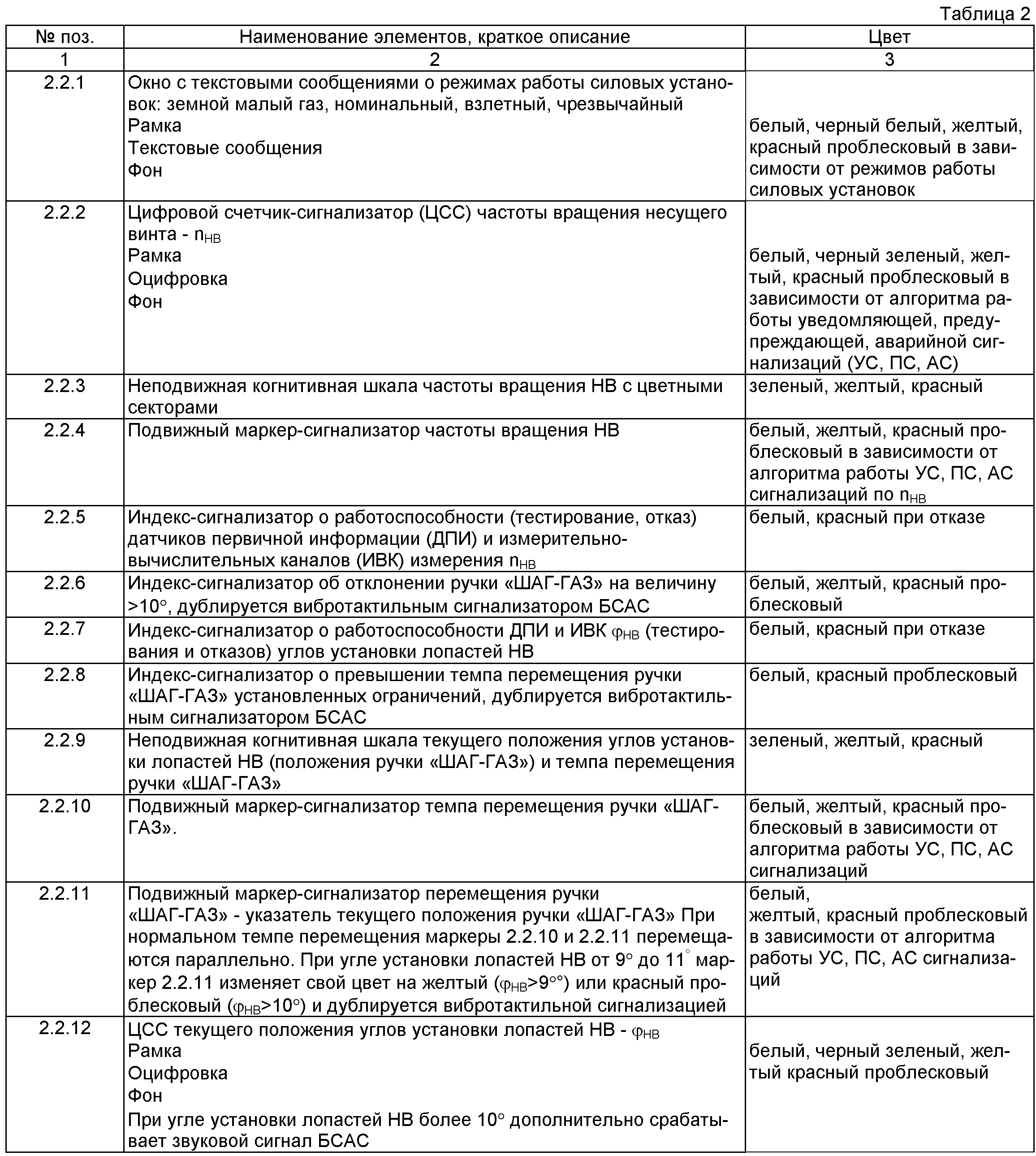
Формат визуального отображения информации о работоспособности и отказах измерительно-вычислительных комплексов, входящих в структуру СВП, показан на Фиг.2 позицией 2.3. Он не требует пояснений: текстовые сообщения об отказах систем СВП отображаются красным цветом, рабочее состояние - зеленым. Дополнительно выведена аварийная сигнализация о наиболее опасных режимах работы СВП (темп НВ, темп РВ, вертикальная скорость, угловая скорость, скорость смещения).The format of the visual display of information about the health and failures of the measuring and computing systems included in the structure of the SVP is shown in figure 2 by the position 2.3. It does not require explanation: text messages about failures of SVP systems are displayed in red, operating status - in green. Additionally, an alarm was issued about the most dangerous modes of operation of the SVP (HB rate, RV rate, vertical speed, angular speed, displacement speed).
Формат визуального представления параметрической и сигнальной информации о пространственном положении вертолета, динамики его движения (Фиг.2 поз.2.4) и его описание показаны на Фиг.4 и таблице 3.The format of the visual representation of the parametric and signal information about the spatial position of the helicopter, the dynamics of its movement (Fig.2 pos.2.4) and its description are shown in Fig.4 and table 3.


Формат визуального отображения параметрической и сигнальной информации о высотных параметрах вертолета и вертикальной скорости (Фиг.2 - поз.2.5) и его описание показаны на Фиг.5 и таблице 4.The format of the visual display of parametric and signal information about the altitude parameters of the helicopter and vertical speed (Figure 2 - item 2.5) and its description are shown in Figure 5 and table 4.

Формат визуального представления параметрической и сигнальной информации о метеорологических условиях полета и максимально допустимых взлетных и посадочных массах вертолета в зависимости от фактических метеорологических условий, способов взлета/посадки, использования ПОС, ПЗУ и правил полетов (Фиг.2 - поз.2.6) и его описание показаны на Фиг.6 и таблице 5.The format of the visual representation of the parametric and signal information about the meteorological conditions of the flight and the maximum allowable take-off and landing masses of the helicopter, depending on the actual meteorological conditions, methods of take-off / landing, the use of PIC, ROM and flight rules (Figure 2 - item 2.6) and its description shown in Fig.6 and table 5.


Использование технических средств визуализации полета одновинтового вертолета в сочетании с применением бортовой системы аварийно-предупреждающей сигнализации, функционирующей на различных физических принципах (световая, звуковая, тактильная), а также применение цветовой когнитивной графики значительно уменьшают психофизиологическую нагрузку на членов экипажа и сокращают их ошибочные действия при пилотировании вертолета в СМУ, особенно на малых и предельно малых высотах, зонах взлета и посадки в быстроменяющейся аэродинамической обстановке за счет создания индикации, соответствующей эффективному образу полета, приближенному к визуальному.The use of single-rotor helicopter flight visualization equipment in combination with the use of an onboard alarm system operating on various physical principles (light, sound, tactile), as well as the use of color cognitive graphics significantly reduce the psychophysiological load on crew members and reduce their erroneous actions when helicopter piloting in SMU, especially at low and extremely low altitudes, take-off and landing zones in a rapidly changing aerodynamic situation by creating an indication corresponding to an effective image of flight, close to visual.
Таким образом, когнитивный пилотажный индикатор расширяет функциональные возможности ИКБО вертолета в части повышения уровня осведомленности экипажа по пилотажным и навигационным параметрам, позволяющим безошибочно оценить сложившуюся аэродинамическую ситуацию в сложных метеорологических условиях, в т.ч. при потере экипажем визуальной видимости подстилающей поверхности и ориентиров на ней. Это позволяет уменьшить время принятия решений по управлению вертолетом за счет сокращения числа логических операций, уменьшения «зон сомнений» (логических операций, выполняемых членами экипажа при дефиците (или отсутствии) информации за счет представления экипажу полного набора параметров аэродинамики полета вертолета, параметров управления и параметров внешних воздействующих факторов).Thus, the cognitive aerobatic indicator expands the functionality of the IKBO helicopter in terms of increasing the crew's awareness of aerobatic and navigation parameters, allowing to accurately assess the current aerodynamic situation in difficult weather conditions, including when the crew loses visual visibility of the underlying surface and landmarks on it. This allows you to reduce the decision-making time for helicopter control by reducing the number of logical operations, reducing “zones of doubt” (logical operations performed by crew members with a deficit (or lack) of information by presenting the crew with a complete set of helicopter flight aerodynamics, control parameters and parameters external factors).
СВП в отличие от прототипа дополнительно в своем составе содержит современный измерительно-вычислительную систему, аппаратно содержащую в своем составе:SVP, in contrast to the prototype, additionally contains a modern measuring and computing system, which contains in hardware:
- электронный измерительно-вычислительный комплекс, предназначенный для определения параметров пространственного положения вертолета и динамики движения вертолета с учетом особенностей его динамики и возможностью определения путевой скорости продольного и поперечного перемещения вертолета (вперед-назад, влево-вправо), угловых скоростей вращения относительно связанных осей вертолета, определения малых величин углов крена, тангажа на стоянке до запуска силовых установок, в процессе запуска силовых установок и раскрутки трансмиссии в моменты отрыва/приземления, висения, вертикального набора высоты, снижения с функциональными возможностями обеспечения безопасности взлетов и посадок на необорудованные площадки и площадки, подобранные с воздуха, имеющие различные углы наклона (продольные и поперечные), неизвестную плотность покрытия, вызывающего при посадке неравномерную просадку пневматиков шасси с последующим опрокидыванием вертолета (определение углов наклона ВВПП). Дополнительно вышеназванный блок вырабатывает аварийно-предупреждающую визуальную сигнальную информацию, выполненную с применением когнитивных технологий, и продублированную звуковой тональной сигнализацией;- an electronic measuring and computing complex designed to determine the parameters of the spatial position of the helicopter and the dynamics of the movement of the helicopter, taking into account the peculiarities of its dynamics and the ability to determine the directional speed of the longitudinal and transverse movement of the helicopter (forward-backward, left-right), angular speeds of rotation relative to the associated axes of the helicopter , determination of small values of the angle of heel, pitch in the parking lot before the launch of the power plants, in the process of starting the power plants and the promotion of the transmission moments of separation / landing, hovering, vertical climb, decrease with functional capabilities to ensure the safety of takeoffs and landings on unequipped and airborne platforms with different angles of inclination (longitudinal and transverse), unknown coating density, which causes an uneven subsidence of pneumatics during landing landing gear followed by rollover of the helicopter (determination of the inclination angles of the runway). Additionally, the above-mentioned unit generates alarm-warning visual signaling information made using cognitive technologies and duplicated by audible tone signaling;
- электронный измерительно-вычислительный комплекс, предназначенный для определения высотно-скоростных параметров и метеорологических параметров, влияющих на безопасность полета: истинной воздушной скорости, в том числе и в диапазоне малых скоростей, приборной скорости, абсолютной барометрической высоты, относительной барометрической высоты, вертикальной скорости снижения/набора, скорости и направления ветра, продольной и поперечной составляющих скорости ветра, величины атмосферного давления, температуры наружного воздуха, определения максимально допустимых взлетных/посадочных масс в зависимости от методов и способов взлета, непосредственно зависящих от метеоусловий в месте взлета и посадки с аварийно предупреждающими сигнализаторами достижения вертолетом минимально безопасной высоты полета, опасной скорости полета, опасной скорости ветра и его боковой и попутной составляющих, опасной вертикальной скорости снижения для предотвращения попадания вертолета в режим «ВИХРЕВОЕ КОЛЬЦО»;- an electronic measuring and computing complex designed to determine altitude and speed parameters and meteorological parameters affecting flight safety: true airspeed, including in the low-speed range, instrument speed, absolute barometric altitude, relative barometric altitude, vertical descent rate / set, wind speed and direction, longitudinal and transverse components of wind speed, atmospheric pressure, outdoor temperature, determine the maximum permissible take-off / landing masses depending on the take-off methods and methods, which directly depend on the weather conditions at the take-off and landing site with alarm warning indicators that the helicopter has reached the minimum safe flight altitude, dangerous flight speed, dangerous wind speed and its lateral and associated components, dangerous vertical rate of descent to prevent the helicopter from entering the "VORTEX RING" mode;
- электронный измерительно-вычислительный комплекс, предназначенный для определения параметров органов управления и динамики их движения: угла отклонения ручки «ШАГ-ГАЗ» и темпа его перемещения, темпа перемещения педалей управления шагом РВ, параметров динамики вращения НВ и режимов работы силовых установок с визуальными и тактильными аварийно-предупреждающими сигнализаторами опасного темпа перемещения ручки «ШАГ-ГАЗ», опасного темпа перемещения педалей управления углами установки лопастей РВ, опасного падения/превышения частоты вращения НВ;- an electronic measuring and computing complex designed to determine the parameters of the controls and the dynamics of their movement: the angle of deviation of the STEP-GAS knob and its rate of movement, the rate of movement of the pedals of control of the pitch RV, the parameters of the dynamics of rotation of the HB and the operating modes of power plants with visual and tactile emergency warning indicators of a dangerous pace of movement of the STEP-GAS handle, a dangerous pace of movement of the pedals to control the angles of installation of the blades of the propeller, a dangerous fall / overspeed in HB expansion;
- аппаратные и аппаратно-программные средства комплексирования видеоизображений подстилающей поверхности и подвижных/неподвижных препятствий на ней с целью получения улучшенного инструментального изображения закабинного пространства при любых метеорологических условиях и независимо от характера покрытия ВВПП;- hardware and hardware-software tools for integrating video images of the underlying surface and moving / stationary obstacles on it in order to obtain an improved instrumental image of the cockpit space under any meteorological conditions and regardless of the nature of the runway cover;
- электронные средства аварийно-предупреждающей сигнализации: визуальные, звуковые, тактильные о приближении и выходе контролируемых параметров полета на границы летных эксплуатационных значений в соответствии с требованиями РЛЭ и аэродинамики конкретного типа вертолета, функционирующие на принципах когнитивности и работающие с динамическим и статическим упреждением.- electronic means of alarm warning: visual, audible, tactile about the approach and exit of the controlled flight parameters to the boundaries of flight operational values in accordance with the requirements of the flight characteristics and aerodynamics of a particular type of helicopter, operating on the principles of cognition and working with dynamic and static anticipation.
Другим отличием является использование нового формата представления пилотажной (параметрической и сигнальной) визуальной информации, обеспечивающей повышение эффективности управления вертолетом и безошибочность управляющих действий за счет:Another difference is the use of a new format for the presentation of aerobatic (parametric and signal) visual information, which provides an increase in the effectiveness of helicopter control and the accuracy of control actions due to:
- отображения информации на индикаторах - комбинере ИЛС, навигационном индикаторе и КПИ, интуитивно напоминающих экипажу условия пилотирования вертолета по правилам визуальных полетов (ПВП), т.е. в простых метеорологических условиях, за счет применения когнитивного представления пилотажной, навигационной и сигнальной информации на них;- displaying information on indicators - ILS combiner, navigation indicator and KPI, intuitively reminding the crew of the conditions for piloting a helicopter according to the rules of visual flights (PVP), i.e. in simple meteorological conditions, due to the application of the cognitive presentation of aerobatic, navigation and signal information on them;
- создания средств отображения информации, на информационном поле которых выполнено отображение функционально сгруппированных приборов, максимально приближенных к индикаторам пространственного положения вертолета и которые не требуют концентрации внимания зрительного анализатора, минимизирующих необходимость переключения внимания, обеспечивающая быстрое, точное, легкое восприятие параметрической и сигнальной информации (с первого взгляда) для всех пространственных положений вертолета, и которые позволяют экипажу выполнить эффективный ручной вывод вертолета в безопасный режим полета из любого пространственного положения;- creation of information display tools, on the information field of which functionally grouped devices are displayed, which are as close as possible to the indicators of the spatial position of the helicopter and which do not require the attention of the visual analyzer, minimizing the need for switching attention, providing quick, accurate, easy perception of parametric and signal information (with at a glance) for all spatial positions of the helicopter, and which allow the crew to perform effective tive manual output of the helicopter in flight safe mode from any spatial position;
- создания визуального информационного обеспечения, характеризующего особенности динамики полета вертолета, параметры внешних воздействующих факторов, особенности управления вертолетом (координация движения, темп перемещения, соразмерность, направление);- creation of visual information support characterizing the characteristics of the dynamics of the flight of the helicopter, the parameters of external influencing factors, especially the control of the helicopter (coordination of movement, pace of movement, proportionality, direction);
- применения способа отображения параметрической и сигнальной информации, необходимой для безопасного пилотирования вертолета на всех этапах и режимах полета, имеющей верхние/нижние пределы в полном диапазоне отображаемой информации без применения шкально-стрелочных индикаторов (или индикаторов «типа часы»), которые заменены на цифровые счетчики-сигнализаторы, неподвижные/подвижные и всплывающие индексы, всплывающие текстовые сообщения, включающие изменение цвета фона цифрового счетчика и цвета фона индексов в зависимости от величины текущего значения контролируемого параметра (зеленый, желтый, красный проблесковый) и в зависимости от алгоритмов работы уведомляющей, предупреждающей и аварийной сигнализации, выполненной со статическим и динамическим упреждением. Данные средства отличаются тем, что изменением цвета фона ЦСС (цифровой счетчик-сигнализатор) отображается тенденция изменения параметра, что не требует обращения членов экипажа к долговременной памяти для анализа многочисленных летных эксплутационных ограничений параметров полета вертолета, зависящих в свою очередь от этапов, режимов полета, полетной массы, заставляющих экипаж обращаться к долговременной памяти и необходимости производить в уме оперативные действия по вычислению допустимых значений контролируемых параметров, что значительно снижает психофизиологическую нагрузку на экипаж при инструментальном пилотировании вертолета в сложных метеорологических условиях, а значит, направлено на предотвращение ошибочных действий пилота (экипажа) и соответственно на повышение уровня безопасности полета.- the use of a method for displaying parametric and signal information necessary for safe piloting of a helicopter at all stages and flight modes, having upper / lower limits in the full range of displayed information without the use of dial indicators (or “clock type” indicators), which are replaced by digital counters, fixed / movable and pop-up indices, pop-up text messages, including a change in the background color of the digital counter and the background color of the indices depending on the values us the current value of the monitored parameter (green, yellow, red flashing) and depending on the operation algorithms notifying, warning and alarm performed with static and dynamic feedforward. These tools are distinguished by the fact that a change in the background color of the CSS (digital counter-signaling device) shows a tendency for a parameter to change, which does not require crew members to access long-term memory to analyze the numerous flight operational limitations of the helicopter flight parameters, which in turn depend on the stages and flight modes, flight mass, forcing the crew to turn to long-term memory and the need to perform operational actions in the mind to calculate the permissible values of the controlled parameters, which nachitelno psychophysiological reduces crew workload during tool piloting the helicopter in adverse weather conditions, and therefore, is directed to preventing erroneous action pilot (crew) and correspondingly to improve safety of flight.
Предложенные СВП и КПИ позволяют значительно расширить функциональные возможности существующих средств информационного обеспечения за счет представления экипажу визуального отображения параметров динамики движения вертолета, его пространственного положения и местоположения на всех этапах и режимах полета, характерных для одновинтовых вертолетов, независимо от времени года, суток при любых метеорологических условиях, в том числе и при видимости, близкой к нулю, и которые дополнительно обеспечивают:The proposed SVP and KPI can significantly expand the functionality of existing information support tools by presenting to the crew a visual display of the parameters of the dynamics of the helicopter's motion, its spatial position and location at all stages and flight modes characteristic of single-rotor helicopters, regardless of the time of year or day at any meteorological conditions, including when visibility is close to zero, and which additionally provide:
- индикацию (представление экипажу на комбинере ИЛС, расположенном на фоне лобового стекла остекления фонаря кабины вертолета) линии искусственного горизонта при любых метеоусловиях полета, которая по своему положению, перемещению соответствует линии истинного (естественного) горизонта, видимой членами экипажа из кабины вертолета в простых метеорологических условиях. В этом случае у экипажа есть «пространство неба», «плоскость земли» и линия горизонта, расположенная в глубине индикатора за счет применения 3D-формата;- indication (presentation to the crew at the ILS combiner, located against the background of the windshield of the glazing of the helicopter cockpit lantern) of the artificial horizon line for any weather conditions of flight, which in its position, movement corresponds to the line of the true (natural) horizon, visible by crew members from the helicopter cabin in simple meteorological conditions. In this case, the crew has “sky space”, “earth plane” and a horizon line located in the depth of the indicator due to the use of 3D-format;
- индикацию положения и перемещения «своего» вертолета в пространстве, который отображается на полноцветном когнитивном пилотажном индикаторе вертолета (КПИ) в виде макета вертолета (для пилотов удобнее и привычнее - в виде макета самолета), движущегося по крену относительно неподвижной условной линии горизонта на фоне подвижной линии, разделяющей «пространство неба» и «плоскость Земли» - вращающейся картушки, расположенной «в глубине» индикатора в 3D-формате. При этом индикация пространственного положения выполняется в соответствии с требованиями эргономики и не вызывает у экипажа психофизической нагрузки при определении пространственного положения вертолета, так как направление поворота (перемещения) органов управления вертолетом полностью соответствует вращению макета самолета в ту же сторону как по темпу, так и по соразмерности движения органов управления и полностью соответствует вращению самого вертолета относительно плоскости земного горизонта;- an indication of the position and movement of “one's own” helicopter in the space that is displayed on the full-color cognitive flight indicator of the helicopter (KPI) in the form of a helicopter model (for pilots it is more convenient and more familiar as a model of an aircraft) moving along a roll relative to a fixed conditional horizon on the background a moving line dividing the "space of the sky" and the "plane of the Earth" - a rotating card located "in the depth" of the indicator in 3D format. In this case, the indication of the spatial position is performed in accordance with the requirements of ergonomics and does not cause the crew psychophysical load when determining the spatial position of the helicopter, since the direction of rotation (movement) of the helicopter controls fully corresponds to the rotation of the model of the aircraft in the same direction both in tempo and in the proportionality of the movement of the controls and fully corresponds to the rotation of the helicopter itself relative to the plane of the earth's horizon;
- индикацию перемещения вертолета вперед-назад, влево-вправо, вращения влево-вправо относительно подстилающей поверхности на режимах висения, перемещения на малых высотах, взлета, вертикальном снижении и приземлении;- indication of the movement of the helicopter back and forth, left-right, rotation left-right relative to the underlying surface in the hovering modes, moving at low altitudes, take-off, vertical descent and landing;
- индикацию траектории снижения относительно плоскости истинного горизонта в зоне ограничений вертикальной скорости снижения с учетом поступательной скорости снижения и истинной высоты полета, необходимых экипажу для предотвращения попадания вертолета в режим «вихревое кольцо»;- indication of the descent trajectory relative to the plane of the true horizon in the zone of limitations of the vertical descent velocity, taking into account the translational descent velocity and the true flight altitude, necessary for the crew to prevent the helicopter from entering the vortex ring mode;
- индикацию темпа (скорости) перемещения рычага «ШАГ-ГАЗ» и педалей управления углами установки лопастей РВ;- indication of the pace (speed) of movement of the STEP-GAZ lever and pedals of control of the angles of installation of the blades of the propeller;
- индикацию максимально допустимой взлетной/посадочной массы в зависимости от способов взлета/посадки, определенной для фактических метеорологических условий в местах взлета/посадки;- an indication of the maximum permissible take-off / landing weight, depending on the take-off / landing methods, determined for the actual meteorological conditions at the take-off / landing sites;
- индикацию информации о фактических метеорологических условиях полета - скорости и метеорологического направления ветра, величинах атмосферного давления на высоте уровня расположения ВВПП и температуры наружного воздуха, продольной и поперечной составляющих скорости ветра;- an indication of information on the actual meteorological conditions of the flight — wind speed and meteorological direction, atmospheric pressure values at the height of the runway and the outdoor temperature, longitudinal and transverse components of the wind speed;
- индикацию информации о характере препятствий (неподвижные и подвижные объекты, их высота и расстояние до них) и техническом состоянии поверхности ВВПП (ямы, бугры и др.) предполагаемого места приземления и о предварительной оценке углов продольного и поперечного уклонов места приземления до момента попадания вертолета в снежный или пыльный вихрь на высоте не менее 100 метров, позволяющей экипажу оценить возможность производства безопасной посадки;- an indication of the nature of the obstacles (fixed and moving objects, their height and distance to them) and the technical condition of the runway surface (pits, mounds, etc.) of the proposed landing site and a preliminary assessment of the angles of the longitudinal and transverse slopes of the landing site before the helicopter hits into a snowy or dusty whirlwind at a height of at least 100 meters, allowing the crew to evaluate the possibility of making a safe landing;
- индикацию продольных и поперечных углов вертолетной взлетно-посадочной площадки перед запуском силовых установок и раскрутки трансмиссии, рулении, в моменты отрыва и приземления вертолета;- indication of the longitudinal and transverse angles of the helipad before launching the power plants and the promotion of the transmission, taxiing, at the moment of separation and landing of the helicopter;
- индикацию аварийной предупреждающей сигнальной информации (визуальной, а также звуковой, тактильной), оповещающей экипаж о приближении параметрической информации к максимально/минимально допустимым в условиях эксплуатации значениям, необходимой экипажу для безопасного пилотирования вертолета по следующим параметрам:- indication of emergency warning signaling information (visual, as well as audible, tactile) informing the crew about the approach of the parametric information to the maximum / minimum acceptable values in the operating conditions necessary for the crew to safely pilot the helicopter in the following parameters:
- угол наклона ВВПП предполагаемого места приземления на этапе снижения и захода на посадку на высотах не менее 100 метров;- the inclination angle of the runway runway of the intended landing site at the stage of descent and approach at altitudes of at least 100 meters;
- угол наклона ВВПП на этапах до запуска силовых установок, руления, отрыва и приземления вертолета;- the inclination angle of the runway at the stages prior to the launch of power plants, taxiing, separation and landing of the helicopter;
- углы крена и тангажа на всех режимах полета вертолета в соответствии с существующими эксплутационными ограничениями;- roll and pitch angles in all helicopter flight modes in accordance with existing operational restrictions;
- продольные, поперечные скорости перемещения вертолета на этапах маневрирования на малых высотах, висения, вертикального набора высоты и снижения, приземления;- longitudinal, transverse speeds of the helicopter at the stages of maneuvering at low altitudes, hovering, vertical climb and descent, landing;
- угловая скорость рыскания на всех этапах и режимах полета;- angular yaw rate at all stages and flight modes;
- продольная и поперечная составляющие скорости ветра на этапах до запуска силовых установок, руления, перемещения на малых высотах, вертикального набора высоты и снижения;- the longitudinal and transverse components of the wind speed at the stages prior to the launch of power plants, taxiing, moving at low altitudes, vertical climb and descent;
- визуальная и тактильная сигнализация превышения темпа перемещения ручки «ШАГ-ГАЗ» установленных эксплуатационных ограничений и перемещения ручки «ШАГ-ГАЗ» в положение более 11 градусов (для вертолетов типа Ми-8);- visual and tactile signaling that the STEP-GAZ handle has exceeded the established operating limits and that the STEP-GAZ handle has been moved to a position of more than 11 degrees (for Mi-8 type helicopters);
- визуальная и тактильная сигнализация падения/превышения частоты вращения НВ установленных эксплуатационных ограничений.- visual and tactile signaling of the fall / excess of the rotational speed of the HB of the established operational limitations.
Заявленные система визуализации полета и когнитивный пилотажный индикатор базируются на современной элементной базе, освоенной промышленностью. В программно-аппаратном комплексе использованы последние достижения науки и техники в области формирования улучшенного отображения подстилающей поверхности. Разработаны новые алгоритмы определения параметров динамики движения вертолета, его управления, параметров внешних воздействующих факторов.The claimed flight visualization system and cognitive flight indicator are based on a modern elemental base mastered by the industry. The hardware and software complex uses the latest achievements of science and technology in the field of forming an improved display of the underlying surface. New algorithms have been developed for determining the parameters of the dynamics of helicopter motion, its control, and the parameters of external influencing factors.
Таким образом, удается достичь заявленного технического результата для системы визуализации полета, а именно: создание улучшенной системы визуализации пилотажных параметров полета и закабинного пространства, функционирующей при любых метеорологических условиях на всех этапах и режимах полета вертолета независимо от технических характеристик подстилающей поверхности, включающей улучшенную бортовую систему аварийно-предупреждающей сигнальной информации, за счет разработки дополнительных электронных измерительно-вычислительных комплексов и существенного расширения функциональных возможностей существующих бортовых систем вертолета.Thus, it is possible to achieve the claimed technical result for the flight visualization system, namely: the creation of an improved visualization system for the flight parameters of the flight and the cockpit, which functions under any meteorological conditions at all stages and flight modes of the helicopter, regardless of the technical characteristics of the underlying surface, including an improved airborne system alarm warning information due to the development of additional electronic measuring and computing to complexes and a significant expansion of the functionality of the existing onboard helicopter systems.
А также достичь технического результата для когнитивного пилотажного индикатора: создание нового формата представления пилотажно-навигационной информации, выполненного с применением когнитивных технологий, который позволяет экипажу осуществить эффективный ручной вывод вертолета из любого пространственного положения в безопасный режим полета.And also to achieve a technical result for a cognitive aerobatic indicator: the creation of a new format for the presentation of aerobatic and navigation information, made using cognitive technologies, which allows the crew to carry out effective manual removal of the helicopter from any spatial position to a safe flight mode.
Claims (6)
Priority Applications (1)
| Application Number | Priority Date | Filing Date | Title |
|---|---|---|---|
| RU2012119086/08A RU2497175C1 (en) | 2012-05-11 | 2012-05-11 | Flight display system and cognitive flight display for single-rotor helicopter |
Applications Claiming Priority (1)
| Application Number | Priority Date | Filing Date | Title |
|---|---|---|---|
| RU2012119086/08A RU2497175C1 (en) | 2012-05-11 | 2012-05-11 | Flight display system and cognitive flight display for single-rotor helicopter |
Publications (1)
| Publication Number | Publication Date |
|---|---|
| RU2497175C1 true RU2497175C1 (en) | 2013-10-27 |
Family
ID=49446858
Family Applications (1)
| Application Number | Title | Priority Date | Filing Date |
|---|---|---|---|
| RU2012119086/08A RU2497175C1 (en) | 2012-05-11 | 2012-05-11 | Flight display system and cognitive flight display for single-rotor helicopter |
Country Status (1)
| Country | Link |
|---|---|
| RU (1) | RU2497175C1 (en) |
Cited By (12)
| Publication number | Priority date | Publication date | Assignee | Title |
|---|---|---|---|---|
| RU2591029C1 (en) * | 2015-02-13 | 2016-07-10 | Российская Федерация, от имени которой выступает Министерство промышленности и торговли Российской Федерации (Минпромторг России) | Method of improved image of underlying surface producing on (ac) aircraft |
| RU168333U1 (en) * | 2016-11-03 | 2017-01-30 | Федеральное государственное бюджетное образовательное учреждение высшего образования "Тверской государственный университет" | SYNTHESIS VISION DEVICE |
| RU2640496C1 (en) * | 2016-07-25 | 2018-01-09 | Александр Валерьевич Погудин | Method of increasing active and passive safety of civilian aircrafts |
| RU2653414C1 (en) * | 2017-02-02 | 2018-05-08 | Сергей Николаевич Низов | Stalling warning system |
| CN110737277A (en) * | 2018-07-18 | 2020-01-31 | 松下知识产权经营株式会社 | Unmanned aerial vehicle, information processing method, and program recording medium |
| CN111141277A (en) * | 2020-01-16 | 2020-05-12 | 中国地质科学院地球物理地球化学勘查研究所 | Aviation navigation system and aviation equipment |
| RU2729891C1 (en) * | 2019-02-15 | 2020-08-13 | Валерий Николаевич Егоров | Intelligent man-machine interface of helicopter crew on altitude-speed parameters and parameters of air environment surrounding helicopter |
| RU2733178C1 (en) * | 2019-12-16 | 2020-09-29 | Общество с ограниченной ответственностью "Научно Инженерная Компания" | Method for configuration of aircraft cockpit information field |
| RU2751581C2 (en) * | 2016-10-06 | 2021-07-15 | Юниверситэ Д'Э-Марсей | Systems for measuring the distance to an obstacle using an optical flow |
| RU2753992C2 (en) * | 2017-04-06 | 2021-08-25 | Зе Боинг Компани | Vertical landing vehicle, system and method for providing awareness of situation |
| RU2778716C2 (en) * | 2020-12-22 | 2022-08-23 | Николай Павлович Бездетнов | Command and flight indicator of helicopter |
| CN120403654A (en) * | 2025-05-30 | 2025-08-01 | 福建鼎旸信息科技股份有限公司 | Multi-channel low-altitude helicopter communication and navigation signal enhancement method and system |
Citations (5)
| Publication number | Priority date | Publication date | Assignee | Title |
|---|---|---|---|---|
| US6092058A (en) * | 1998-01-08 | 2000-07-18 | The United States Of America As Represented By The Secretary Of The Army | Automatic aiding of human cognitive functions with computerized displays |
| RU2280888C2 (en) * | 2002-12-24 | 2006-07-27 | Федеральное государственное унитарное предприятие Летно-исследовательский институт имени М.М. Громова | Method of performing descent at landing approach |
| US20070208725A1 (en) * | 2006-03-03 | 2007-09-06 | Mike Gilger | Displaying common operational pictures |
| RU2348981C1 (en) * | 2007-07-03 | 2009-03-10 | Владимир Тарасович Артемов | Method of independent formation of landing information for flying machine and system for its realisation (versions) |
| RU2410719C2 (en) * | 2009-03-02 | 2011-01-27 | Владимир Иванович Винокуров | Method of preventing collision of helicopters with high-voltage power transmission lines |
-
2012
- 2012-05-11 RU RU2012119086/08A patent/RU2497175C1/en not_active IP Right Cessation
Patent Citations (5)
| Publication number | Priority date | Publication date | Assignee | Title |
|---|---|---|---|---|
| US6092058A (en) * | 1998-01-08 | 2000-07-18 | The United States Of America As Represented By The Secretary Of The Army | Automatic aiding of human cognitive functions with computerized displays |
| RU2280888C2 (en) * | 2002-12-24 | 2006-07-27 | Федеральное государственное унитарное предприятие Летно-исследовательский институт имени М.М. Громова | Method of performing descent at landing approach |
| US20070208725A1 (en) * | 2006-03-03 | 2007-09-06 | Mike Gilger | Displaying common operational pictures |
| RU2348981C1 (en) * | 2007-07-03 | 2009-03-10 | Владимир Тарасович Артемов | Method of independent formation of landing information for flying machine and system for its realisation (versions) |
| RU2410719C2 (en) * | 2009-03-02 | 2011-01-27 | Владимир Иванович Винокуров | Method of preventing collision of helicopters with high-voltage power transmission lines |
Cited By (17)
| Publication number | Priority date | Publication date | Assignee | Title |
|---|---|---|---|---|
| RU2591029C1 (en) * | 2015-02-13 | 2016-07-10 | Российская Федерация, от имени которой выступает Министерство промышленности и торговли Российской Федерации (Минпромторг России) | Method of improved image of underlying surface producing on (ac) aircraft |
| RU2640496C1 (en) * | 2016-07-25 | 2018-01-09 | Александр Валерьевич Погудин | Method of increasing active and passive safety of civilian aircrafts |
| RU2751581C2 (en) * | 2016-10-06 | 2021-07-15 | Юниверситэ Д'Э-Марсей | Systems for measuring the distance to an obstacle using an optical flow |
| RU168333U1 (en) * | 2016-11-03 | 2017-01-30 | Федеральное государственное бюджетное образовательное учреждение высшего образования "Тверской государственный университет" | SYNTHESIS VISION DEVICE |
| RU2653414C1 (en) * | 2017-02-02 | 2018-05-08 | Сергей Николаевич Низов | Stalling warning system |
| RU2753992C2 (en) * | 2017-04-06 | 2021-08-25 | Зе Боинг Компани | Vertical landing vehicle, system and method for providing awareness of situation |
| CN110737277A (en) * | 2018-07-18 | 2020-01-31 | 松下知识产权经营株式会社 | Unmanned aerial vehicle, information processing method, and program recording medium |
| RU2729891C1 (en) * | 2019-02-15 | 2020-08-13 | Валерий Николаевич Егоров | Intelligent man-machine interface of helicopter crew on altitude-speed parameters and parameters of air environment surrounding helicopter |
| RU2733178C1 (en) * | 2019-12-16 | 2020-09-29 | Общество с ограниченной ответственностью "Научно Инженерная Компания" | Method for configuration of aircraft cockpit information field |
| CN111141277A (en) * | 2020-01-16 | 2020-05-12 | 中国地质科学院地球物理地球化学勘查研究所 | Aviation navigation system and aviation equipment |
| RU2778716C2 (en) * | 2020-12-22 | 2022-08-23 | Николай Павлович Бездетнов | Command and flight indicator of helicopter |
| RU2787317C1 (en) * | 2021-10-15 | 2023-01-09 | Федеральное автономное учреждение "Государственный научно-исследовательский институт авиационных систем" (ФАУ "ГосНИИАС") | System for ergonomic assessment of the control and navigation equipment |
| RU2782993C1 (en) * | 2021-12-29 | 2022-11-08 | Федеральное государственное автономное образовательное учреждение высшего образования "Южно-Уральский государственный университет (национальный исследовательский университет)" ФГАОУ ВО "ЮУрГУ (НИУ)" | Method for predictive control of the functional reliability of a helicopter pilot when applying night vision goggles |
| RU2827876C1 (en) * | 2023-04-07 | 2024-10-03 | Акционерное общество "Научно-исследовательский институт по измерительной технике - радиотехнические комплексы имени А.М. Брейгина" | Method of controlling aircraft landing on ship using augmented virtual reality means |
| CN120403654A (en) * | 2025-05-30 | 2025-08-01 | 福建鼎旸信息科技股份有限公司 | Multi-channel low-altitude helicopter communication and navigation signal enhancement method and system |
| RU238705U1 (en) * | 2025-07-11 | 2025-11-11 | Федеральное государственное бюджетное учреждение "Национальный исследовательский Центр "Институт имени Н.Е. Жуковского" (ФГБУ "НИЦ "Институт имени Н.Е. Жуковского") | On-board indicator calculator |
| RU2857898C1 (en) * | 2025-10-10 | 2026-03-11 | Федеральное государственное бюджетное учреждение "Национальный исследовательский Центр "Институт имени Н.Е. Жуковского" (ФГБУ "НИЦ "Институт имени Н.Е. Жуковского") | System for displaying integrated flight and navigation information on external vision displays |
Similar Documents
| Publication | Publication Date | Title |
|---|---|---|
| RU2497175C1 (en) | Flight display system and cognitive flight display for single-rotor helicopter | |
| RU2550887C2 (en) | On-board integrated crew support information system and cognitive format of presenting flight information at take-off phase of multi-engine aircraft | |
| US7280896B2 (en) | Process and device for constructing a synthetic image of the environment of an aircraft and presenting it on a screen of said aircraft | |
| US7312725B2 (en) | Display system for operating a device with reduced out-the-window visibility | |
| US7215256B2 (en) | Method and apparatus for displaying attitude, heading, and terrain data | |
| US7486291B2 (en) | Systems and methods using enhanced vision to provide out-the-window displays for a device | |
| CN105549938B (en) | System and method for displaying runway landing information | |
| US9037319B2 (en) | System and method for processing and displaying wake turbulence | |
| EP2148175B1 (en) | Aircraft display systems and methods for enhanced display of landing information | |
| US8010245B2 (en) | Aircraft systems and methods for displaying a touchdown point | |
| EP2148176B1 (en) | Aircraft display system with obstacle warning envelope | |
| EP2685442B1 (en) | System for displaying runway information | |
| US20050098681A1 (en) | System and method for controlling the acoustic signature of a device | |
| US8188890B2 (en) | Systems and methods for enhancing obstacles and terrain profile awareness | |
| EP3111170B1 (en) | Projected synthetic vision | |
| US20190162555A1 (en) | System and method for 3d flight path display | |
| US20100161158A1 (en) | Systems and methods for enhancing terrain elevation awareness | |
| EP2830032A1 (en) | Aircraft flight deck display, system and method for displaying integrated minimum safe altitude and minimum vectoring altitude information on a display device in an aircraft | |
| US20140002280A1 (en) | Apparatus and method for displaying a helicopter approach to an airport landing pad | |
| RU2647344C2 (en) | Take-off and landing display system of the aircraft | |
| RU39960U1 (en) | INFORMATION TEAM LEADER SYSTEM | |
| WO2005050601A2 (en) | Display systems for a device | |
| RU2310909C1 (en) | Flight simulating pilotage complex | |
| RU49297U1 (en) | INFORMATION AND MANAGEMENT COMPLEX OF AIRCRAFT | |
| US20180010922A1 (en) | Method for automatically adapting the range of visibility in a three-dimensional synthetic representation of the outside landscape in an on-board display system for aircraft |
Legal Events
| Date | Code | Title | Description |
|---|---|---|---|
| MM4A | The patent is invalid due to non-payment of fees |
Effective date: 20180512 |