KR20160051404A - Autostereoscopic 3d display device and driving method thereof - Google Patents
Autostereoscopic 3d display device and driving method thereof Download PDFInfo
- Publication number
- KR20160051404A KR20160051404A KR1020140151339A KR20140151339A KR20160051404A KR 20160051404 A KR20160051404 A KR 20160051404A KR 1020140151339 A KR1020140151339 A KR 1020140151339A KR 20140151339 A KR20140151339 A KR 20140151339A KR 20160051404 A KR20160051404 A KR 20160051404A
- Authority
- KR
- South Korea
- Prior art keywords
- filter
- view
- image
- users
- input data
- Prior art date
- Legal status (The legal status is an assumption and is not a legal conclusion. Google has not performed a legal analysis and makes no representation as to the accuracy of the status listed.)
- Granted
Links
Images


Classifications
-
- H—ELECTRICITY
- H04—ELECTRIC COMMUNICATION TECHNIQUE
- H04N—PICTORIAL COMMUNICATION, e.g. TELEVISION
- H04N13/00—Stereoscopic video systems; Multi-view video systems; Details thereof
- H04N13/10—Processing, recording or transmission of stereoscopic or multi-view image signals
- H04N13/106—Processing image signals
- H04N13/122—Improving the three-dimensional [3D] impression of stereoscopic images by modifying image signal contents, e.g. by filtering or adding monoscopic depth cues
-
- H—ELECTRICITY
- H04—ELECTRIC COMMUNICATION TECHNIQUE
- H04N—PICTORIAL COMMUNICATION, e.g. TELEVISION
- H04N13/00—Stereoscopic video systems; Multi-view video systems; Details thereof
- H04N13/30—Image reproducers
- H04N13/302—Image reproducers for viewing without the aid of special glasses, i.e. using autostereoscopic displays
-
- H—ELECTRICITY
- H04—ELECTRIC COMMUNICATION TECHNIQUE
- H04N—PICTORIAL COMMUNICATION, e.g. TELEVISION
- H04N13/00—Stereoscopic video systems; Multi-view video systems; Details thereof
- H04N13/30—Image reproducers
- H04N13/366—Image reproducers using viewer tracking
- H04N13/383—Image reproducers using viewer tracking for tracking with gaze detection, i.e. detecting the lines of sight of the viewer's eyes
Landscapes
- Engineering & Computer Science (AREA)
- Multimedia (AREA)
- Signal Processing (AREA)
- Testing, Inspecting, Measuring Of Stereoscopic Televisions And Televisions (AREA)
Abstract
본 발명의 무안경 입체영상표시장치 및 그 구동방법은 아이-트랙킹(eye tracking)을 통해 사용자(user)의 수를 파악하여 사용자의 수에 따라 스위처블 3D 필터의 개구를 제어하는 것을 특징으로 한다.
이에 따라 사용자의 수에 따라 적절한 입체영상을 제공하는 한편, 1인 사용자가 시청하는 경우에는 다수 사용자를 위한 멀티 뷰(multi view) 영상을 2뷰 영상으로 변환시킴으로서 입체영상표시장치의 해상도 및 휘도를 향상시키는 효과를 제공한다.The non-eyeglass stereoscopic image display apparatus and the driving method thereof according to the present invention are characterized by controlling the opening of the switchable 3D filter according to the number of users by counting the number of users through eye tracking .
Accordingly, when a single user views a multi-view image, a multi-view image is converted into a 2-view image to provide a resolution and brightness of the stereoscopic image display device Thereby providing an effect of improving the performance.
Description
본 발명은 입체영상표시장치에 관한 것으로, 보다 상세하게는 안경을 착용하지 않는 방식의 무안경 입체영상표시장치 및 그 구동방법에 관한 것이다.BACKGROUND OF THE
3D 디스플레이(display)란 간단히 정의를 내리자면 "인위적으로 3D 화면을 재생시켜 주는 시스템의 총체"라고 할 수 있다.A simple definition of 3D display is "the total system that artificially reproduces the 3D screen".
여기서, 시스템이란 3D로 보여질 수 있는 소프트웨어적인 기술과 그 소프트웨어적 기술로 만든 컨텐츠를 실제로 3D로 구현해내는 하드웨어를 동시에 포함한다. 소프트웨어 영역까지 포함시키는 이유는 3D 디스플레이 하드웨어의 경우 각각의 입체 구현방식마다 별도의 소프트웨어적 방식으로 구성된 컨텐츠가 따로 필요하기 때문이다.Here, the system includes a software technique that can be viewed in 3D and a hardware that actually realizes the content created by the software technique in 3D. The reason for incorporating the software area is that the 3D display hardware requires separately configured contents in a separate software manner for each stereoscopic implementation method.
또한, 가상 3D 디스플레이(이하, 입체영상표시장치라 함)는 사람이 입체감을 느끼는 여러 요인 중 우리 눈이 가로방향으로 약 65mm 떨어져 있어서 나타나게 되는 양안시차(binocular disparity)를 이용하여 평면적인 디스플레이 하드웨어에서 말 그대로 가상적으로 입체감을 느낄 수 있게 하는 시스템의 총체이다. 다시 말해 우리의 눈은 양안시차 때문에 똑같은 사물을 바라보더라도 각각 약간은(정확히 말하면 좌우의 공간적 정보를 약간씩 나눠 가지고 있는) 다른 화상을 보게 되고, 이 두 화상이 망막을 통해 뇌로 전달되면 뇌는 이를 정확히 서로 융합시킴으로써 우리가 입체감을 느낄 수 있게 되는데, 그것을 이용하여 2D 디스플레이 장치에서 좌우 화상 2개를 동시에 표시하여 각각의 눈으로 보내는 설계를 통해 가상적인 입체감을 만들어 내는 것이 바로 입체영상표시장치인 것이다.In addition, a virtual 3D display (hereinafter, referred to as a stereoscopic image display device) is a type of stereoscopic image display device that uses a binocular disparity, which is caused by a distance of about 65 mm It is the totality of the system that allows you to literally feel the stereoscopic effect. In other words, our eyes see a different image (a little bit of space between the left and the right, respectively) even if we look at the same things because of binocular parallax. When these two images are transmitted to the brain through the retina, Dimensional stereoscopic image display apparatus is a stereoscopic image display apparatus in which two left and right images are simultaneously displayed on a 2D display apparatus and sent to each eye by using a stereoscopic image display apparatus .
이러한 입체영상표시장치에서 하나의 화면으로 두 채널의 화상을 나타내기 위해서는 대부분의 경우 하나의 화면에서 가로나 세로의 한쪽 방향으로 줄을 한 줄씩 바꿔가며 한 채널씩 출력하게 된다. 그렇게 동시에 두 채널의 화상이 하나의 디스플레이 장치에서 출력되면 하드웨어적 구조상 무안경 방식의 경우에는 오른쪽 화상은 그대로 오른쪽 눈으로 들어가고, 왼쪽 화상은 왼쪽 눈으로만 들어가게 된다. 또한, 안경을 착용하는 방식의 경우에는 각각의 방식에 맞는 특수한 안경을 통하여 오른쪽 화상은 왼쪽 눈이 볼 수 없게 가려주고, 왼쪽 화상은 오른쪽 눈이 볼 수 없게 각각 가려주는 방법을 사용한다.In order to display images of two channels in one screen in such a stereoscopic image display device, in most cases, one line is changed one line at a time horizontally or vertically in one screen and outputted one channel at a time. At the same time, when images of two channels are output from one display device, in the case of a non-eyeglass system due to the hardware structure, the right image enters the right eye as it is, and the left image enters only the left eye. In addition, in the case of wearing the glasses, the right image is visually obscured by the special glasses suitable for each method, and the left image is obscured by the right eye so that the right eye can not be seen.
이와 같이 사람이 입체감과 깊이감을 느끼는 요인으로 가장 중요하게는 두 눈 사이의 간격에 의한 양안시차를 들 수 있지만, 이외에도 심리적, 기억적 요인에도 깊은 관계가 있고, 이에 따라 입체 구현방식 역시 관찰자에게 어느 정도의 3차원 영상정보를 제공할 수 있는지를 기준으로 통상 부피표현방식(volumetric type), 3차원표현방식(holographic type), 입체감표현방식(stereoscopic type)으로 구분된다.As mentioned above, the binocular parallax due to the interval between the two eyes is the most important factor for the person to feel the three-dimensional feeling and the depth feeling, but there is also a deep relationship with the psychological and memory factors. Accordingly, Dimensional image information, a volumetric type, a holographic type, and a stereoscopic type based on whether the three-dimensional image information can be provided.
부피표현방식은 심리적인 요인과 흡입효과에 의해 깊이방향에 대한 원근감이 느껴지도록 하는 방법으로서, 투시도법, 중첩, 음영과 명암, 움직임 등을 계산에 의해 표시하는 3차원 컴퓨터그래픽, 또는 관찰자에게 시야각이 넓은 대화면을 제공하여 그 공간 내로 빨려 들어가는 것 같은 착시현상을 불러일으키는 이른바 아이맥스 영화 등에 응용되고 있다.The volume expression method is a method for making the depth direction perceive by the psychological factors and the suction effect, and is a three-dimensional computer graphic which displays the perspective method, overlapping, shading, contrast, and movement by calculation, So-called IMAX films, which give rise to an optical illusion that it is sucked into the space by providing a large screen.
가장 완전한 입체영상 구현기술이라 알려져 있는 3차원표현방식은 레이저광 재생 홀로그래피(holography) 내지 백색광 재생 홀로그래피로 대표될 수 있다.The three-dimensional representation known as the most complete stereoscopic imaging technique can be represented by laser light reproduction holography or white light reproduction holography.
그리고, 입체감표현방식은 양안의 생리적 요인을 이용하여 입체감을 느끼는 방식으로, 전술한 바와 같이 약 65㎜ 떨어져 존재하는 인간의 좌, 우안에 시차정보가 포함된 평면의 연관 영상이 보일 경우에 뇌가 이들을 융합하는 과정에서 표시면 전후의 공간정보를 생성해 입체감을 느끼는 능력, 즉 입체 사진술(stereography)을 이용한 것이다. 이러한 입체감표현방식은 크게 안경을 착용하는 방식과 안경을 착용하지 않는 무안경 방식이 있다.As described above, when an association image of a plane including parallax information is displayed on the left and right sides of a human being present at a distance of about 65 mm as described above, the brain expresses three-dimensional images using the physiological factors of both eyes. And the ability to generate spatial information before and after the display surface in the process of fusing them to sense a stereoscopic effect, that is, stereography. Such a three-dimensional expression system is largely classified into a system in which glasses are worn and a system in which glasses are not worn.
안경을 착용하지 않는 방식으로서 알려진 대표적인 것으로는 원통형의 렌즈를 수직으로 배열한 렌티큘러(lenticular) 렌즈판을 영상패널 전방에 설치하는 렌티큘러 렌즈 방식과 패러렉스 배리어(parallax barrier) 방식이 있다.Representative known methods of not wearing glasses include a lenticular lens method and a parallax barrier method in which a lenticular lens plate vertically arranging a cylindrical lens is installed in front of the image panel.
도 1은 일반적인 패러렉스 배리어 방식의 입체영상표시장치의 개념을 설명하기 위한 도면이다.FIG. 1 is a view for explaining the concept of a stereoscopic image display apparatus of a general parallax barrier system.
도 1을 참조하면, 일반적인 패러렉스 배리어 방식의 입체영상표시장치는 좌, 우안용 영상을 동시에 표시하는 영상패널(image panel)(40) 및 영상패널(40)의 전면(前面)에 배치된 배리어 셀(20)로 구성된다.1, a typical parallax barrier stereoscopic image display apparatus includes an
영상패널(40)에는 좌안용 영상을 표시하는 좌안 화소(L)와 우안용 영상을 표시하는 우안 화소(R)가 번갈아 정의되어 있고, 영상패널(40)과 사용자(user)(30) 사이에 배리어 셀(20)이 배치된다.A left eye pixel L for displaying a left eye image and a right eye pixel R for displaying a right eye image are alternately defined in the
배리어 셀(20)은 패러렉스 배리어로 불리는 가느다란 배리어(barrier)(21) 사이에 슬릿(slit)(22)이 형성되어 배리어 셀(20)을 통해 좌, 우안 영상이 분리되어 동시에 표시되게 된다.The
이에 따라 영상패널(40)의 좌안 화소(L)에 표시되는 좌안용 영상은 배리어 셀(20)의 슬릿(22)을 거쳐 사용자(30)의 좌안에 도달되고, 영상패널(40)의 우안 화소(R)에 표시되는 우안용 영상은 배리어 셀(20)의 슬릿(22)을 거쳐 사용자(30)의 우안에 도달되는데, 이때 좌, 우안용 영상에는 각각 인간이 감지 가능한 시차(視差)를 고려한 별개의 영상이 담겨 있고, 사용자(30)는 이 2가지 영상을 결합하여 3D 영상을 인식하게 된다.The left eye image displayed on the left eye pixel L of the
이러한 무안경 입체영상표시장치는 좌우 영상을 볼 수 있는 2뷰(view)로 구동될 수 있는데, 이 경우 좌우 영상이 바뀌어 보이는 역입체시의 확률이 높아 텔레비전(television)과 같은 다수 사용자를 위한 디스플레이에는 멀티 뷰(multi view)로 영상을 구동하게 된다.Such a non-eyeglass stereoscopic image display apparatus can be driven with two views for viewing left and right images. In this case, since the probability of reverse stereoscopic viewing that the left and right images are changed is high, The image is driven in a multi view.
2뷰의 경우 최적 시청거리(Optimal Viewing Distance; OVD)에서 역입체시의 경우가 50%의 확률로 존재한다.2 view, there is a 50% probability of inverse stereoacuity in Optimal Viewing Distance (OVD).
전술한 멀티 뷰 구동은 좌우 영상들이 정상적으로 도달하는 뷰잉 다이아몬드(viewing diamond)를 다수 생성하여 역입체시 영역을 줄이는 장점이 있지만, 해상도와 휘도가 단안 기준으로 1/(멀티 뷰 개수)로 낮아지는 단점이 있다.The above-described multi-view driving is advantageous in reducing the inverse stereoscopic area by generating a large number of viewing diamonds in which the left and right images normally reach, but it is disadvantageous in that resolution and luminance are reduced to 1 / (multi view number) .
즉, 디스플레이의 휘도는 각 서브-화소들의 빛이 눈으로 조사될 때의 총합으로 나타낼 수 있다. 하지만, 무안경 입체영상표시장치의 경우에는 좌안과 우안에 다른 영상을 보여주기 위해 빛의 방향성을 조절하게 된다. 따라서, 단안에 보이는 서브-화소의 개수가 디스플레이 전체의 서브-화소의 개수보다 작으며, 이에 따라 단안 기준으로 해상도와 휘도가 감소하게 된다.That is, the luminance of the display can be expressed by the sum of the light of each sub-pixel when the eye is irradiated with light. However, in the case of a non-eyeglass stereoscopic image display device, the direction of light is adjusted to display different images in the left eye and the right eye. Therefore, the number of sub-pixels seen in a single view is smaller than the number of sub-pixels in the entire display, thereby reducing the resolution and brightness on a monocular basis.
특히, 다수 사용자를 위한 멀티 뷰는 뷰의 개수만큼 해상도와 휘도가 감소하게 된다.In particular, multi-view for multiple users reduces resolution and brightness by the number of views.
본 발명은 상기한 문제를 해결하기 위한 것으로, 사용자의 수에 따라 적절한 입체영상을 제공하며, 입체영상의 3D 크로스토크의 저하 없이 해상도와 휘도를 향상시키도록 한 무안경 입체영상표시장치 및 그 구동방법을 제공하는데 목적이 있다.SUMMARY OF THE INVENTION The present invention has been made to solve the above problems and it is an object of the present invention to provide a stereoscopic image display apparatus and stereoscopic image display apparatus capable of providing an appropriate stereoscopic image according to the number of users and improving resolution and luminance without deteriorating 3D crosstalk of stereoscopic images, A method is provided.
기타, 본 발명의 다른 목적 및 특징들은 후술되는 발명의 구성 및 특허청구범위에서 설명될 것이다.Other objects and features of the present invention will be described in the following description of the invention and the claims.
상기한 목적을 달성하기 위하여, 본 발명의 일 실시예에 따른 무안경 입체영상표시장치는 멀티 뷰의 입력 데이터를 표시하는 영상패널, 영상패널의 전면에 배치되며, 투과부와 차단부로 이루어져 입력 데이터의 광축을 분리하여 입체영상을 구현하는 3D 필터 및 영상패널에 구비되어 사용자의 수 및 위치를 수집하는 영상수집부를 포함하여 구성될 수 있다.According to an aspect of the present invention, there is provided a non-eyeglass stereoscopic image display device including an image panel for displaying input data of multi-view, a display panel disposed on a front surface of the image panel, A 3D filter for separating the optical axis to realize a stereoscopic image, and an image collecting unit for collecting the number and position of users provided in the image panel.
이때, 본 발명의 일 실시예에 따른 무안경 입체영상표시장치는 영상수집부를 통해 수집된 사용자의 수에 따라 3D 필터의 투과부와 차단부의 위치 및 투과부의 개수를 제어하는 3D 필터 제어부를 포함할 수 있다.The non-eyeglass stereoscopic image display apparatus according to an embodiment of the present invention may include a 3D filter control unit for controlling the positions of transmissive portions and blocking portions of the 3D filter and the number of transmissive portions according to the number of users collected through the image collection unit have.
본 발명의 일 실시예에 따른 무안경 입체영상표시장치는 사용자의 수에 따라 매핑된 입력 데이터를 영상패널에 공급하는 타이밍 컨트롤러를 추가로 포함할 수 있다.The non-eyeglass stereoscopic image display apparatus according to an embodiment of the present invention may further include a timing controller that supplies input image data mapped according to the number of users to the image panel.
본 발명의 일 실시예에 따른 무안경 입체영상표시장치는 1인 사용자가 시청하는 경우에는 멀티 뷰의 입력 데이터를 2뷰의 입력 데이터로 변환하여 타이밍 컨트롤러에 공급하는 한편, 3D 필터의 구동을 제어하기 위한 제어용 데이터를 생성하여 3D 필터 제어부로 공급하는 멀티 뷰 영상변환부를 추가로 포함할 수 있다.In a non-eyeglass stereoscopic image display apparatus according to an embodiment of the present invention, when one user views, input data of a multi-view is converted into input data of two views and supplied to a timing controller, And a multi-view image converting unit for generating control data for supplying the control data to the 3D filter control unit.
3D 필터는 제 1 필름, 제 1 필름의 하부면에 구비된 제 1 선편광자, 제 1 필름의 상부면에 구비된 분할전극들, 제 1 필름과 이격 대향하는 제 2 필름, 제 2 필름의 상부면에 구비된 제 2 선편광자, 제 2 필름의 하부면에 구비된 전면전극 및 제 1 필름과 제 2 필름 사이에 위치하는 액정층을 포함하여 구성될 수 있다.The 3D filter includes a first film, a first linear polarizer provided on a lower surface of the first film, split electrodes provided on an upper surface of the first film, a second film spaced apart from the first film, And a liquid crystal layer disposed between the first film and the second film. The liquid crystal layer may include a second linear polarizer provided on the first film, a front electrode provided on the lower surface of the second film, and a liquid crystal layer disposed between the first film and the second film.
이때, 3D 필터는 3D 필터 제어부의 제어 하에 분할전극들에 서로 다른 전압이 공급되어, 영상패널에 표시된 입력 데이터를 투과시키는 투과부와 차단시키는 차단부를 구현하며, 반복적으로 배치된 다수의 투과부와 차단부는 세트를 구성할 수 있다.At this time, the 3D filter implements a cutoff portion which is supplied with different voltages from the divided electrodes under the control of the 3D filter control portion and cuts off the transmission portion which transmits the input data displayed on the image panel, and the plurality of repeatedly arranged transmission portions and cutoff portions A set can be constructed.
이때, 다수의 사용자가 시청할 경우, 3D 필터의 하나의 세트에는 하나의 투과부가 구성될 수 있다.At this time, when a plurality of users view, one transmission portion may be configured for one set of 3D filters.
또는, 1인의 사용자가 시청할 경우, 3D 필터의 하나의 세트에는 2개 이상의 투과부가 구성될 수 있다.Alternatively, when one user views, two or more transmissive portions may be configured in one set of 3D filters.
또한, 본 발명의 일 실시예에 따른 무안경 입체영상표시장치의 구동방법은 영상수집부를 통해 사용자의 수 및 시청위치를 수집하는 단계, 수집된 사용자의 수를 바탕으로 사용자가 2인 이상의 다수인지 1인인지 판단하는 단계, 수집된 사용자의 수 및 시청위치에 대응하여 멀티 뷰의 입력 데이터를 맵핑하는 단계 및 수집된 사용자의 수 및 시청위치에 대응하여 3D 필터 제어부를 통해 3D 필터를 제어함과 더불어 매핑된 멀티 뷰의 입력 데이터를 영상패널을 통해 출력하는 단계를 포함하여 구성될 수 있다.According to another aspect of the present invention, there is provided a method for driving a spectacles stereoscopic image display apparatus, comprising the steps of: collecting a number of users and a viewing position through an image collection unit; Mapping the input data of the multi-view corresponding to the number of collected users and the viewing position, and controlling the 3D filter through the 3D filter control unit in correspondence with the number of collected users and the viewing position, And outputting the input data of the mapped multi-view through the image panel.
이때, 3D 필터 제어부는 영상수집부에 수집된 사용자의 수에 따라 3D 필터의 투과부와 차단부의 위치 및 투과부의 개수를 제어할 수 있다.At this time, the 3D filter control unit can control the positions of the transmissive part and the blocking part and the number of transmissive parts of the 3D filter according to the number of users collected in the image collecting part.
이때, 호스트 시스템을 통해 사용자가 1인인 경우 2뷰로 구동되는 제 1 뷰 모드로 설정하고, 사용자가 2인 이상의 다수인 경우 멀티 뷰(3뷰 이상)로 구동되는 제 2 뷰 모드로 설정할 수 있다.At this time, the first view mode may be set to be driven by two views when the user is one person through the host system, and may be set to the second view mode which is driven by the multi view (three or more views) when the user is a plurality of two or more persons.
이때, 제 1 뷰 모드로 설정된 경우에는 멀티 뷰의 입력 데이터를 2뷰의 입력 데이터로 변환하여 타이밍 컨트롤러로 공급하는 반면, 제 2 뷰 모드로 설정된 경우에는 멀티 뷰의 입력 데이터를 수집된 사용자의 수 및 시청위치에 따라 맵핑하여 타이밍 컨트롤러로 공급할 수 있다.At this time, when the mode is set to the first view mode, input data of the multi-view is converted into input data of two views and supplied to the timing controller. On the other hand, when the mode is set to the second view mode, And can be supplied to the timing controller by mapping according to the viewing position.
제 1 모드로 설정된 경우에는 2뷰에 대한 구동 전압 추출 과정을 실시하고, 3D 필터의 투과부와 차단부를 영상패널에 표시된 2뷰 영상에 대응하여 조절할 수 있다.When the mode is set to the first mode, a driving voltage extraction process for two views is performed, and the transmission portion and the blocking portion of the 3D filter can be adjusted corresponding to the two view images displayed on the image panel.
이때, 3D 필터 제어부는 3D 필터에 하나의 세트당 2뷰 영상만 투과시키는 2개 이상의 개구부와 나머지를 차단시키는 차단부로 제어할 수 있다.At this time, the 3D filter control unit can control at least two openings through which only two view images per one set are transmitted to the 3D filter, and a blocking unit that blocks the rest.
또는. 제 2 모드로 설정되는 경우에는 다수의 뷰에 대한 구동 전압 추출 과정을 실시하고, 3D 필터의 개구부와 차단부를 영상패널에 표시된 다수개의 멀티 뷰 영상에 대응하여 조절할 수 있다.or. When the second mode is set, a driving voltage extraction process for a plurality of views is performed, and the opening and blocking portions of the 3D filter can be adjusted corresponding to a plurality of multi-view images displayed on the image panel.
이때, 3D 필터 제어부는 3D 필터에 하나의 세트당 다수개의 멀티 뷰 영상을 투과시키는 하나의 개구부와 나머지를 차단시키는 차단부로 제어할 수 있다.At this time, the 3D filter control unit can control the 3D filter with one opening for transmitting a plurality of multi-view images per set and a blocking unit for blocking the rest.
상술한 바와 같이, 본 발명에 따른 무안경 입체영상표시장치 및 그 구동방법은 아이-트랙킹(eye tracking)을 통해 사용자(user)의 수를 파악하여 사용자의 수에 따라 스위처블 3D 필터의 개구를 제어하는 것을 특징으로 한다.As described above, the non-eyeglass stereoscopic image display apparatus and the driving method thereof according to the present invention grasps the number of users through eye tracking and determines the aperture of the switchable 3D filter according to the number of users And a control unit.
이에 따라 사용자의 수에 따라 적절한 입체영상을 제공하는 한편, 1인 사용자가 시청하는 경우에는 다수 사용자를 위한 멀티 뷰(multi view) 영상을 2뷰 영상으로 변환시킴으로서 입체영상표시장치의 해상도 및 휘도를 향상시키는 효과를 제공한다.Accordingly, when a single user views a multi-view image, a multi-view image is converted into a 2-view image to provide a resolution and brightness of the stereoscopic image display device Thereby providing an effect of improving the performance.
도 1은 일반적인 패러렉스 배리어 방식의 입체영상표시장치의 개념을 설명하기 위한 도면.
도 2는 본 발명의 실시예에 따른 무안경 입체영상표시장치의 구성을 개략적으로 보여주는 블록도.
도 3은 도 2에 도시된 영상패널의 서브-화소 구조를 예시적으로 보여주는 도면.
도 4는 본 발명의 실시예에 따른 무안경 입체영상표시장치의 구동방법을 순차적으로 보여주는 흐름도.
도 5는 다수의 사용자가 시청하는 경우에 있어, 3D 필터의 구동을 설명하기 위한 단면도.
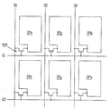
도 6은 다수의 사용자가 시청하는 경우에 있어, 무안경 입체영상표시장치의 구동을 예시적으로 보여주는 도면.
도 7은 1인의 사용자가 시청하는 경우에 있어, 3D 필터의 구동을 설명하기 위한 단면도.
도 8은 1인의 사용자가 시청하는 경우에 있어, 무안경 입체영상표시장치의 구동을 예시적으로 보여주는 도면.BRIEF DESCRIPTION OF THE DRAWINGS Fig. 1 is a diagram for explaining the concept of a stereoscopic image display apparatus in a general parallax barrier system. Fig.
2 is a block diagram schematically illustrating the configuration of a spectacle-free three-dimensional image display apparatus according to an embodiment of the present invention.
3 is an exemplary view illustrating a sub-pixel structure of the image panel shown in FIG. 2. FIG.
4 is a flowchart sequentially illustrating a method of driving a spectacle-free three-dimensional image display apparatus according to an embodiment of the present invention.
5 is a cross-sectional view for explaining driving of a 3D filter in the case where a plurality of users watches;
FIG. 6 is a diagram exemplarily showing driving of a spectacles stereoscopic image display apparatus when a plurality of users view the same; FIG.
7 is a cross-sectional view for explaining the driving of a 3D filter in the case where a single user views it;
8 is a diagram exemplarily showing driving of a spectacles stereoscopic image display apparatus when a single user views the apparatus.
이하, 첨부한 도면을 참조하여 본 발명에 따른 무안경 입체영상표시장치 및 그 구동방법의 바람직한 실시예를 본 발명이 속하는 기술분야에서 통상의 지식을 가진 자가 용이하게 실시할 수 있도록 상세히 설명한다.DETAILED DESCRIPTION OF THE PREFERRED EMBODIMENTS Reference will now be made in detail to the present embodiments of the present invention, examples of which are illustrated in the accompanying drawings, wherein like reference numerals refer to the like elements throughout.
본 발명의 이점 및 특징, 그리고 그것들을 달성하는 방법은 첨부되는 도면과 함께 상세하게 후술되어 있는 실시예들을 참조하면 명확해질 것이다. 그러나, 본 발명은 이하에서 개시되는 실시예들에 한정되는 것이 아니라 서로 다른 다양한 형태로 구현될 것이며, 단지 본 실시예들은 본 발명의 개시가 완전하도록 하며, 본 발명이 속하는 기술분야에서 통상의 지식을 가진 자에게 발명의 범주를 완전하게 알려주기 위해 제공되는 것이며, 본 발명은 청구항의 범주에 의해 정의될 뿐이다. 명세서 전체에 걸쳐 동일 참조 부호는 동일 구성요소를 지칭한다. 도면에서 층 및 영역들의 크기 및 상대적인 크기는 설명의 명료성을 위해 과장될 수 있다.BRIEF DESCRIPTION OF THE DRAWINGS The advantages and features of the present invention, and the manner of achieving them, will be apparent from and elucidated with reference to the embodiments described hereinafter in conjunction with the accompanying drawings. It should be understood, however, that the invention is not limited to the disclosed embodiments, but is capable of many different forms and should not be construed as limited to the embodiments set forth herein. Rather, these embodiments are provided so that this disclosure will be thorough and complete, To fully disclose the scope of the invention to those skilled in the art, and the invention is only defined by the scope of the claims. Like reference numerals refer to like elements throughout the specification. The dimensions and relative sizes of the layers and regions in the figures may be exaggerated for clarity of illustration.
소자(element) 또는 층이 다른 소자 또는 "위(on)" 또는 "상(on)"으로 지칭되는 것은 다른 소자 또는 층의 바로 위뿐만 아니라 중간에 다른 층 또는 다른 소자를 개재한 경우를 모두 포함한다. 반면, 소자가 "직접 위(directly on)" 또는 "바로 위"로 지칭되는 것은 중간에 다른 소자 또는 층을 개재하지 않는 것을 나타낸다.It will be understood that when an element or layer is referred to as being another element or "on" or "on ", it includes both intervening layers or other elements in the middle, do. On the other hand, when a device is referred to as "directly on" or "directly above ", it does not intervene another device or layer in the middle.
공간적으로 상대적인 용어인 "아래(below, beneath)", "하부(lower)", "위(above)", "상부(upper)" 등은 도면에 도시되어 있는 바와 같이 하나의 소자 또는 구성 요소들과 다른 소자 또는 구성 요소들과의 상관관계를 용이하게 기술하기 위해 사용될 수 있다. 공간적으로 상대적인 용어는 도면에 도시되어 있는 방향에 더하여 사용시 또는 동작시 소자의 서로 다른 방향을 포함하는 용어로 이해되어야 한다. 예를 들면, 도면에 도시되어 있는 소자를 뒤집을 경우, 다른 소자의 "아래(below)" 또는 "아래(beneath)"로 기술된 소자는 다른 소자의 "위(above)"에 놓여질 수 있다. 따라서, 예시적인 용어인 "아래"는 아래와 위의 방향을 모두 포함할 수 있다.The terms spatially relative, "below," "lower," "above," "upper," and the like, And may be used to easily describe the correlation with other elements or components. Spatially relative terms should be understood to include, in addition to the orientation shown in the drawings, terms that include different orientations of the device during use or operation. For example, when inverting an element shown in the figures, an element described as "below" or "beneath" of another element may be placed "above" another element. Thus, the exemplary term "below" can include both downward and upward directions.
본 명세서에서 사용된 용어는 실시예들을 설명하기 위한 것이며, 따라서 본 발명을 제한하고자 하는 것은 아니다. 본 명세서에서, 단수형은 문구에서 특별히 언급하지 않는 한 복수형도 포함한다. 명세서에서 사용되는 "포함한다(comprise)" 및/또는 "포함하는(comprising)"은 언급된 구성요소, 단계, 동작 및/또는 소자는 하나 이상의 다른 구성요소, 단계, 동작 및/또는 소자의 존재 또는 추가를 배제하지 않는다.The terminology used herein is for the purpose of describing embodiments only and is not intended to be limiting of the invention. In the present specification, the singular form includes plural forms unless otherwise specified in the specification. &Quot; comprise "and / or" comprising ", as used in the specification, means that the presence of stated elements, Or additions.
도 2는 본 발명의 실시예에 따른 무안경 입체영상표시장치의 구성을 개략적으로 보여주는 블록도이다.FIG. 2 is a block diagram schematically illustrating the configuration of a non-eyeglass stereoscopic image display apparatus according to an embodiment of the present invention. Referring to FIG.
그리고, 도 3은 도 2에 도시된 영상패널의 서브-화소 구조를 예시적으로 보여주는 도면이다.3 is a view illustrating an exemplary sub-pixel structure of the image panel shown in FIG. 2. Referring to FIG.
도 2 및 도 3을 참조하면, 본 발명의 실시예에 따른 무안경 입체영상표시장치는 크게 영상패널(110), 영상패널 구동부(111, 112), 3D 필터(120), 3D 필터 제어부(116), 3D 필터 구동부(117), 타이밍 컨트롤러(113) 등을 포함하여 구성될 수 있다.2 is a block diagram illustrating a stereoscopic image display apparatus according to an exemplary embodiment of the present invention. The stereoscopic image display apparatus includes an
본 발명에 따른 입체영상표시장치는 액정표시장치(Liquid Crystal Display; LCD), 유기발광표시장치(Organic Light Emitting Diode Display; OLED), 전계발광표시장치(Field Emission Display; FED), 플라즈마영상표시장치(Plasma Display Panel; PDP), 전기발광표시장치(Electroluminescent Display; EL) 등의 평판표시소자로 구현될 수 있다. 본 발명은 아래의 실시예에서 영상패널(110)을 액정표시장치로 구성한 경우를 예시하였지만, 본 발명이 이에 한정되는 것은 아니다.The stereoscopic image display device according to the present invention may be applied to a liquid crystal display (LCD), an organic light emitting diode (OLED) display, a field emission display (FED) A plasma display panel (PDP), or an electroluminescent display (EL). In the following description, the present invention is applied to a case where the
이때, 영상패널(110)에는 적, 녹 및 청색을 표시하는 다수의 서브-픽셀들이 형성되어 있으며, 이러한 서브-픽셀들은 3D 필터(120)와 작용하여 입체영상을 표시하기 위해, 좌안영상과 우안영상을 표시하는 좌안픽셀과 우안픽셀이 구분되어 있다.At this time, a plurality of sub-pixels for displaying red, green and blue colors are formed on the
일 예로, 영상패널(110)을 액정표시장치로 구성하는 경우, 본 발명은 액정표시장치의 액정 모드, 즉 트위스티드 네마틱(Twisted Nematic; TN) 모드, 인-플레인 스위칭(In Plane Switching; IPS) 모드, 프린지 필드 스위칭(Fringe Field Switching; FFS) 모드, 수직배향(Vertical Alignment; VA) 모드 등에 상관없이 적용 가능하다.For example, when the
이때, 도시하지 않았지만, 영상패널(110)은 크게 컬러필터(color filter) 기판과 어레이(array) 기판 및 컬러필터 기판과 어레이 기판 사이에 형성된 액정층으로 구성될 수 있다.Although not shown, the
컬러필터 기판은 적, 녹 및 청의 색상을 구현하는 다수의 서브-컬러필터로 구성된 컬러필터와 서브-컬러필터 사이를 구분하고 액정층을 투과하는 광을 차단하는 블랙매트릭스(Black Matrix; BM), 그리고 액정층에 전압을 인가하는 투명한 공통전극으로 이루어질 수 있다.The color filter substrate includes a black matrix (BM) for separating a sub-color filter from a color filter composed of a plurality of sub-color filters for realizing colors of red, green and blue and blocking light transmitted through the liquid crystal layer, And a transparent common electrode for applying a voltage to the liquid crystal layer.
어레이 기판은 종횡으로 배열되어 다수의 서브-화소(SPr, SPg, SPb)를 정의하는 다수의 게이트라인(G1, G2, G3,..., Gn)과 데이터라인(D1, D2, D3,..., Dm), 게이트라인(G1, G2, G3,..., Gn)과 데이터라인(D1, D2, D3,..., Dm)의 교차영역에 형성된 스위칭소자인 박막 트랜지스터(TFT) 및 서브-화소(SPr, SPg, SPb)에 형성된 화소전극으로 이루어져 있다.The array substrate includes a plurality of gate lines G1, G2, G3, ..., Gn and data lines D1, D2, D3, ..., Gn arranged vertically and horizontally to define a plurality of sub-pixels SPr, SPg, SPb. A thin film transistor TFT which is a switching element formed in an intersection region of the gate lines G1, G2, G3, ..., Gn and the data lines D1, D2, D3, ..., Dm, And pixel electrodes formed in the sub-pixels SPr, SPg, and SPb.
박막 트랜지스터(TFT)는 게이트라인(G1, G2, G3,..., Gn)에 연결된 게이트전극, 데이터라인(D1, D2, D3,..., Dm)에 연결된 소오스전극 및 화소전극에 전기적으로 접속된 드레인전극으로 구성되어 있다.The thin film transistor TFT has a gate electrode connected to the gate lines G1, G2, G3, ..., Gn, a source electrode connected to the data lines D1, D2, D3, ..., Dm, As shown in FIG.
또한, 박막 트랜지스터(TFT)는 게이트전극과 소오스/드레인전극 사이의 절연을 위한 게이트절연막 및 게이트전극에 공급되는 게이트 전압에 의해 소오스전극과 드레인전극 간에 전도채널(conductive channel)을 형성하는 액티브층을 포함한다.In addition, a thin film transistor (TFT) has a gate insulating film for insulation between a gate electrode and a source / drain electrode, and an active layer for forming a conductive channel between a source electrode and a drain electrode by a gate voltage supplied to the gate electrode .
컬러필터 기판의 외면에는 상부 편광판이 부착되고, 어레이 기판의 외면에는 하부 편광판이 부착된다. 상부 편광판의 광투과축과 하부 편광판의 광투과축은 서로 직교되도록 형성될 수 있다. 그리고, 컬러필터 기판과 어레이 기판의 내면에는 액정층의 프리틸트 각(pre-tilt angle)을 설정하기 위한 배향막이 형성되는 한편, 컬러필터 기판과 어레이 기판 사이에는 액정 셀의 셀갭(cell gap)을 유지하기 위한 스페이서가 형성된다.An upper polarizer is attached to the outer surface of the color filter substrate, and a lower polarizer is attached to the outer surface of the array substrate. The light transmission axis of the upper polarizer and the light transmission axis of the lower polarizer may be formed to be orthogonal to each other. An alignment film for setting a pre-tilt angle of the liquid crystal layer is formed on the inner surface of the color filter substrate and the array substrate, and a cell gap of the liquid crystal cell is formed between the color filter substrate and the array substrate. A spacer is formed.
이와 같이 구성되는 영상패널(110)은 타이밍 컨트롤러(113)의 제어 하에 영상을 표시한다.The
영상패널(110)은 타이밍 컨트롤러(113)의 제어 하에 2D 모드에서 2D 영상을 표시하고, 3D 모드에서 멀티 뷰 영상을 표시할 수 있다.The
입체영상의 뷰는 사용자의 양안 간격만큼 카메라들을 이격하고 객체에 대한 이미지를 촬영하여 생성할 수 있다. 일 예로, 9대의 카메라를 이용하여 객체를 촬영하는 경우, 영상패널(110)은 9뷰의 입체영상을 표시할 수 있다.The view of the stereoscopic image can be generated by taking the images of the object by separating the cameras from each other by the interval of the user's eyes. For example, when capturing an object using nine cameras, the
영상패널 구동부(111, 112)는 영상패널(110)의 데이터라인(D1, D2, D3,..., Dm)에 2D/3D 영상의 데이터전압들을 공급하기 위한 데이터 구동부(111)와 영상패널(110)의 게이트라인(G1, G2, G3,..., Gn)들에 스캔 펄스(또는 게이트 펄스)를 순차적으로 공급하기 위한 게이트 구동부(112)를 포함한다. 영상패널 구동부(111, 112)는 3D 모드에서 멀티 뷰 영상 데이터 포맷의 데이터로 입력된 좌안 및 우안 영상 데이터를 영상패널(110)의 서브-픽셀들에 공간적으로 분산하여 기입한다.The image
이때, 도시하지 않았지만, 호스트 시스템(115)에 연결되는 영상수집부는 센서 및 카메라를 이용하여 사용자의 수와 거리, 사용자의 양안 위치 등의 사용자 정보를 감지하여 그 결과를 디지털 데이터로 변화하여 호스트 시스템(115)이나 타이밍 컨트롤러(113)에 공급한다.In this case, although not shown, the image collecting unit connected to the
호스트 시스템(115)이나 타이밍 컨트롤러(113)는 공급받은 사용자 정보에 따라 3D 필터(120)의 구동을 제어하기 위한 제어용 데이터를 생성하여 3D 필터 제어부(116)로 공급한다.The
타이밍 컨트롤러(113)는 데이터 인에이블 신호(Data Enable, DE), 도트 클럭(CLK) 등의 타이밍신호를 입력받아 게이트 구동부(111)와 데이터 구동부(112)의 동작 타이밍을 제어하기 위한 제어신호들(GCS, DCS)을 발생한다.The
즉, 타이밍 컨트롤러(113)는 멀티 뷰 영상 변환부(114)(또는 호스트 시스템(115))로부터 입력받은 영상 데이터와 타이밍 신호들에 기초하여 소정의 프레임 주파수로 영상패널(110)을 구동시키고, 소정의 프레임 주파수를 기준으로 게이트 구동부 제어신호(GCS), 데이터 구동부 제어신호(DCS)를 발생할 수 있다. 타이밍 컨트롤러(113)는 게이트 구동부 제어신호(GCS)를 게이트 구동부(111)로 공급하고, 영상 데이터(R, G, B)와 데이터 구동부 제어신호(DCS)를 데이터 구동부(112)로 공급한다.That is, the
게이트 구동부(111)를 제어하기 위한 게이트 구동부 제어신호(GCS)는 게이트 스타트 펄스(Gate Start Pulse), 게이트 쉬프트 클럭(Gate Shift Clock) 및 게이트 출력 인에이블 신호(Gate Output Enable) 등을 포함한다. 게이트 스타트 펄스는 첫 번째 게이트 펄스의 타이밍을 제어한다. 게이트 쉬프트 클럭은 게이트 스타트 펄스를 쉬프트 시키기 위한 클럭신호이다. 게이트 출력 인에이블 신호는 게이트 구동부(111)의 출력 타이밍을 제어한다.The gate driving unit control signal GCS for controlling the
데이터 구동부(112)를 제어하기 위한 데이터 구동부 제어신호(DCS)는 소스 스타트 펄스(Source Start Pulse), 소스 샘플링 클럭(Source Sampling Clock), 소스 출력 인에이블 신호(Source Output Enable), 극성제어신호 등을 포함한다. 소스 스타트 펄스는 데이터 구동부(112)의 데이터 샘플링 시작 시점을 제어한다. 소스 샘플링 클럭은 라이징 또는 폴링 에지에 기준 하여 데이터 구동부(112)의 샘플링 동작을 제어하는 클럭신호이다. 데이터 구동부(112)에 입력될 디지털 비디오 데이터가 mini LVDS(Low Voltage Differential Signaling) 인터페이스 규격으로 전송된다면, 소스 스타트 펄스와 소스 샘플링 클럭은 생략될 수 있다. 극성제어신호는 데이터 구동부(112)로부터 출력되는 데이터전압의 극성을 L(L은 자연수) 수평기간 주기로 반전시킨다. 소스 출력 인에이블 신호는 데이터 구동부(112)의 출력 타이밍을 제어한다.The data driver control signal DCS for controlling the
데이터 구동부(112)는 다수의 소스 드라이브 IC를 포함한다. 소스 드라이브 IC들은 타이밍 컨트롤러(113)로부터 입력되는 영상 데이터(R, G, B)를 정극성/부극성 감마보상전압으로 변환하여 정극성/부극성 아날로그 데이터전압들을 발생한다. 소스 드라이브 IC들로부터 출력되는 정극성/부극성 아날로그 데이터전압들은 영상패널(110)의 데이터라인(D1, D2, D3,..., Dm)들에 공급된다.The
게이트 구동부(111)는 하나 이상의 게이트 드라이브 IC를 포함한다. 게이트 구동부(111)는 쉬프트 레지스터, 쉬프트 레지스터의 출력신호를 액정 셀의 TFT 구동에 적합한 스윙 폭으로 변환하기 위한 레벨 쉬프터 및 출력 버퍼 등을 포함한다. 게이트 구동부(111)는 타이밍 컨트롤러(113)의 제어 하에 데이터 전압에 동기되는 게이트 펄스를 영상패널(110)의 게이트라인(G1, G2, G3,..., Gn)들에 순차적으로 공급한다.The
특히, 본 발명에 따른 타이밍 컨트롤러(113)는 영상수집부를 통해 검출된 사용자의 수에 따라 적절한 뷰의 입체영상을 제공하는 한편, 1인 사용자가 시청하는 경우에는 다수 사용자를 위한 멀티 뷰 영상을 2뷰 영상으로 변환하는 역할을 수행할 수 있다. 이에 따라 입체영상표시장치의 해상도 및 휘도를 향상시키는 효과를 제공한다.In particular, the
이러한 타이밍 컨트롤러(113)와 호스트 시스템(115) 사이에는 멀티 뷰 영상변환부(114)가 설치될 수 있다. 멀티 뷰 영상변환부(114)는 3D 모드에서 호스트 시스템(115)으로부터 입력되는 3D 영상의 좌안 및 우안 영상 데이터를 사용자 정보를 바탕으로 멀티 뷰 영상 데이터 포맷으로 재 정렬하여 타이밍 컨트롤러(113)에 전송한다.A multi-view
즉, 멀티 뷰 영상변환부(114)는 3D 모드에서 2D 영상 데이터가 입력되면 미리 설정된 2D-3D 영상 변환 알고리즘을 실행하여 2D 영상 데이터로부터 좌안 및 우안 영상 데이터를 생성하고, 그 데이터들을 멀티 뷰 영상 데이터 포맷으로 재 정렬하여 타이밍 컨트롤러(113)에 전송한다.That is, when the 2D image data is input in the 3D mode, the multi-view
호스트 시스템(115)은 TV(television) 시스템, 셋톱박스, 네비게이션 시스템, DVD 플레이어, 블루레이 플레이어, 개인용 컴퓨터(personal computer), 홈 시어터 시스템, 폰 시스템 중 어느 하나로 구현될 수 있다. 호스트 시스템(115)은 스케일러(scaler)를 이용하여 2D/3D 입력 영상의 디지털 비디오 데이터를 영상패널(110)의 해상도에 맞는 포맷으로 변환하고, 그 데이터와 함께 타이밍 신호를 타이밍 컨트롤러(113)로 전송한다.The
호스트 시스템(115)은 2D 모드에서 2D 영상을 타이밍 컨트롤러(113)에 공급하는 한편, 3D 모드에서 3D 영상 또는 2D 영상 데이터를 멀티 뷰 영상변환부(114)에 공급한다. 호스트 시스템(115)은 유저 인터페이스(User Interface; UI)(미도시)를 통해 입력되는 사용자 데이터에 응답하여 타이밍 컨트롤러(113)에 모드 신호를 전송하여 무안경 입체표시장치의 동작 모드를 2D 모드와 3D 모드에서 스위칭 할 수 있다. 유저 인터페이스는 키패드, 키보드, 마우스, 온 스크린 디스플레이(On Screen Display, OSD), 리모트 컨트롤러, 그래픽 유저 인터페이스(Graphic User Interface; GUI), 터치 UI 등으로 구현될 수 있다. 사용자는 유저 인터페이스를 통해 2D 모드와 3D 모드를 선택할 수 있고, 3D 모드에서 2D-3D 영상 변환을 선택할 수 있다.The
즉, 호스트 시스템(115)은 LVDS(Low Voltage Differential Signaling) 인터페이스, TMDS(Transition Minimized Differential Signaling) 인터페이스 등의 인터페이스를 통해 영상 데이터와 타이밍신호들 등을 멀티 뷰 영상변환부(114)에 공급한다. 호스트 시스템(115)은 좌안 영상 데이터와 우안 영상 데이터를 포함하는 3D 영상 데이터를 멀티 뷰 영상변환부(114)에 공급한다. 전술한 바와 같이 타이밍신호들은 수직동기신호, 수평동기신호, 데이터 인에이블 신호(Data Enable), 도트 클럭 등을 포함한다.That is, the
호스트 시스템(115)은 영상수집부로부터 사용자 정보를 입력받고, 사용자 정보에 따라 최적 뷰의 수를 산출한다. 호스트 시스템(115)은 최적 뷰의 수에 따른 뷰 제어신호를 생성하여 멀티 뷰 영상변환부(114)에 공급한다. 호스트 시스템(115)은 사용자 정보의 사용자 수를 입력 어드레스로 받고, 해당 입력 어드레스에 저장된 뷰의 수를 출력하는 룩업테이블을 이용하여 뷰 제어신호를 생성할 수 있다.The
이때, 전술한 바와 같이 1인 사용자가 시청하는 경우로 판단될 때에는 다수 사용자를 위한 멀티 뷰 영상을 2뷰 영상으로 변환하여 타이밍 컨트롤러(113)에 공급하는 한편, 3D 필터(120)의 구동을 제어하기 위한 제어용 데이터를 생성하여 3D 필터 제어부(116)로 공급한다.At this time, when it is determined that one user is watching, the multiview image for a plurality of users is converted into a two-view image and supplied to the
다음으로, 3D 필터(120)는 이미지의 경로를 광학적으로 분리하는 매개체로서, 영상패널(110)의 좌안픽셀과 우안픽셀로부터 출력된 좌안영상과 우안영상을 투과시키거나 차단시키기 위한 광투과 영역과 광차단 영역을 형성하는 기능을 수행한다.Next, the
이러한 3D 필터(120)는 렌티큘러 렌즈 또는 배리어와 같이 기 공지되어 있는 기술들을 이용하여 다양하게 구성될 수 있다. 렌티큘러 렌즈와 배리어는 액정패널을 이용하여 전기적으로 제어되는 스위처블 렌즈(switchable lens)나 스위처블 배리어(switchable barrier)로 구현될 수 있다. 본원 출원인은 미국출원 13/077565, 미국출원 13/325272, 대한민국 출원 10-2010-0030531 등을 통해 스위처블 렌즈나 스위처블 배리어를 제안한 바 있다.Such a
3D 필터 구동부(117)는 타이밍 컨트롤러(113)의 제어 하에 3D 필터 제어부(116)를 통해 3D 모드에서 영상패널(110)의 픽셀 어레이에 기입되는 영상 데이터와 동기되어 스위처블 렌즈나 스위처블 배리어로 이루어진 스위처블 3D 필터(120)를 시프트(shift)시킬 수 있다.The 3D
한편, 전술한 바와 같이 본 발명에서는 아이-트랙킹을 이용하여 사용자의 수를 파악한 후에 사용자의 수에 따라 적절한 입체영상을 제공하는 한편, 1인 사용자가 시청하는 경우에는 다수 사용자를 위한 멀티 뷰 영상을 2뷰 영상으로 변환하여 스위처블 3D 필터를 제어함으로서 입체영상표시장치의 해상도 및 휘도를 향상시킬 수 있는데, 이를 다음의 본 발명에 따른 무안경 입체영상표시장치의 구동방법을 통해 상세히 설명한다.Meanwhile, as described above, in the present invention, the number of users is determined using eye tracking, and then a proper stereoscopic image is provided according to the number of users. On the other hand, when one user views a multi view image, 2 view image to control the switchable 3D filter, the resolution and luminance of the stereoscopic image display device can be improved. Hereinafter, a method of driving the stereoscopic imageless display device according to the present invention will be described in detail.
도 4는 본 발명의 실시예에 따른 무안경 입체영상표시장치의 구동방법을 순차적으로 보여주는 흐름도이다.4 is a flowchart sequentially illustrating a driving method of a spectacle-free stereoscopic image display apparatus according to an embodiment of the present invention.
전술한 바와 같이 본 발명의 실시예에 따른 무안경 입체영상표시장치에는 영상수집부, 호스트 시스템, 멀티 뷰 영상 변환부, 타이밍 컨트롤러, 3D 필터 구동부 및 3D 필터가 구비된다.As described above, the spectacles stereoscopic image display apparatus according to the embodiment of the present invention includes an image collecting unit, a host system, a multi-view image converting unit, a timing controller, a 3D filter driving unit, and a 3D filter.
멀티 뷰 영상변환부는 호스트 시스템으로부터 영상 데이터(RGB), 모드 신호(MODE) 및 뷰 제어신호(Cview)를 입력받는다. 이때, 멀티 뷰 영상변환부는 모드 신호(MODE)에 따라 2D 모드인지 3D 모드인지를 판단할 수 있다(S110).The multi-view image converter receives image data (RGB), a mode signal (MODE) and a view control signal (Cview) from the host system. At this time, the multi-view image converting unit may determine whether the 2D mode or the 3D mode is performed according to the mode signal MODE (S110).
이때, 멀티 뷰 영상변환부는 2D 모드 신호(MODE)가 입력되는 경우, 입력된 2D 영상 데이터를 변환하지 않고 그대로 타이밍 컨트롤러로 출력한다. 그리고, 3D 필터를 전체적으로 오프(off) 구동하여 2D 영상을 구현한다(S155).At this time, when the 2D mode signal (MODE) is inputted, the multi-view image conversion unit outputs the inputted 2D image data to the timing controller as it is without converting. Then, the 3D filter is totally turned off to implement a 2D image (S155).
반면에, 멀티 뷰 영상변환부는 3D 모드 신호(MODE)가 입력되는 경우, 입력된 2D 영상 데이터를 3D 영상 데이터로 변환하여 타이밍 컨트롤러로 출력하는데, 이를 위해 영상수집부를 통해 사용자의 수 및 시청위치 등의 사용자 정보를 검출한다(S120).On the other hand, when the 3D mode signal MODE is input, the multi-view image conversion unit converts the input 2D image data into 3D image data and outputs the 3D image data to the timing controller. For this purpose, (S120). ≪ / RTI >
일 예로, 영상수집부에 의한 아이-트랙킹(eye tracking) 알고리즘은 다음과 같다. 본원 출원인은 대한민국 출원 10-2013-0038815 등을 통해 아이-트랙킹 알고리즘을 제안한 바 있다. 다만, 본 발명이 이에 한정되는 것은 아니다.For example, the eye tracking algorithm by the image collection unit is as follows. The applicant of the present application has proposed an eye-tracking algorithm through Korean Application No. 10-2013-0038815. However, the present invention is not limited thereto.
우선, 카메라를 통해 촬영된 입력 영상으로부터 사용자의 수 및 사용자의 얼굴을 검출한다. 예를 들면, 하르 분류기(Haar Classifier) 등과 같은 얼굴 검출 방법을 이용하여 입력 영상으로부터 사용자의 얼굴을 검출한다.First, the number of users and the user's face are detected from the input image captured through the camera. For example, a user's face is detected from an input image using a face detection method such as Haar Classifier.
이후, 검출된 사용자의 얼굴에서 눈 중심 좌표, 즉 좌안과 우안 사이의 중심 좌표를 검출한다. 예를 들면, AAM(Active Appearance Model) 등과 같은 눈 모델을 이용하여 좌안 및 우안과 같은 초기의 특징점들을 선정한 다음, EBGM 모델 등을 통해 최종 특징점인 눈 중심 좌표를 검출한다.Then, the center coordinates of the eyes of the detected face of the user, that is, the center coordinates between the left eye and the right eye are detected. For example, eye feature models such as AAM (Active Appearance Model) are used to select initial feature points such as the left eye and right eye, and eye center coordinates, which are the final feature points, are detected through an EBGM model.
이후, 검출된 눈 중심 좌표를 이용하여 눈을 이용한 거리 모델에 적용하여 사용자의 눈 위치 정보를 산출한다. 사용자의 눈 위치 정보는 입체영상표시장치의 중심점을 기준으로 한 X, Y, Z 좌표 값으로 산출된다.Then, the eye position information of the user is calculated by applying the detected eye center coordinates to the distance model using the eyes. The user's eye position information is calculated as X, Y, Z coordinate values based on the center point of the stereoscopic image display device.
다음으로, 3D 영상 데이터를 획득한다. 이때, 3D 영상 데이터는 사이드 바이 사이드(side by side), 탑 바텀(top bottom) 등의 좌, 우안 영상으로 획득할 수 있다.Next, 3D image data is acquired. At this time, the 3D image data can be obtained as left and right eye images such as side by side, top bottom, and the like.
이때, 3D 영상 데이터를 먼저 획득한 이후 사용자의 수 및 시청위치를 검출할 수 있다.At this time, the number of users and the viewing position can be detected after acquiring the 3D image data first.
다음으로, 검출된 사용자 정보를 이용하여 사용자가 2인 이상의 다수인지 1인인지 판단한다(S130).Next, using the detected user information, it is determined whether the user is one or more than two (S130).
다음으로, 사용자의 수 및 시청위치에 대응하여 3D 영상 데이터를 맵핑한다(S140, S145). 사용자의 수 및 시청위치에 대응하여 3D 영상 데이터를 맵핑하는 과정은 멀티 뷰 영상 변환부의 영상처리 과정에 의해 이루어진다.Next, 3D image data is mapped corresponding to the number of users and the viewing position (S140, S145). The process of mapping the 3D image data corresponding to the number of users and the viewing position is performed by an image processing process of the multi-view image converting unit.
이때, 사용자의 수가 1명인 경우 2뷰로 구동되는 제 1 뷰 모드로 설정되고, 사용자의 수가 2명 이상인 경우 멀티 뷰(3뷰 이상)로 구동되는 제 2 뷰 모드로 설정될 수 있다.In this case, if the number of users is one, the first view mode is set to be driven by two views. If the number of users is two or more, the second view mode may be set to be driven by multi view (three or more views).
전술한 호스트 시스템에는 뷰 신호 생성부 및 영상 공급부가 포함될 수 있다. 뷰 신호 생성부는 영상수집부를 통해 사용자의 수 및 시청위치가 검출되면 이에 대응하여 뷰의 수 및 뷰의 위치 신호를 생성한다. 즉, 검출된 사용자 정보를 통해 제 1 뷰 모드로 설정되는 경우 뷰 신호 생성부는 2뷰 신호를 생성하는 한편, 제 2 뷰 모드로 설정되는 경우 뷰 신호 생성부는 사용자의 수에 대응하여 3뷰 이상의 뷰 신호를 생성한다.The host system may include a view signal generator and an image supply unit. When the number of viewers and the viewing position are detected through the image collecting unit, the view signal generating unit generates the number of views and the position signal of the view corresponding thereto. That is, when the first view mode is set through the detected user information, the view signal generating unit generates two view signals. On the other hand, when the second view mode is set, the view signal generating unit generates view signals of three or more views Signal.
멀티 뷰 영상 변환부에는 신호 판단부, 영상 룩업테이블 및 영상 데이터 맵핑부가 포함될 수 있다. 영상 룩업테이블에는 뷰의 수 및 뷰의 위치 신호 중 뷰의 수별로 영상 데이터를 재구성하는 영상 데이터 맵이 저장된다. 신호 판단부는 뷰의 수 및 뷰의 위치 신호에 대응하여 영상 룩업테이블에 저장된 데이터 맵을 추출한다. 영상 데이터 맵핑부는 신호 판단부에 의해 추출된 영상 데이터 맵을 이용하여 타이밍 컨트롤러에 공급할 멀티 뷰 영상 데이터를 맵핑한다.The multi-view image conversion unit may include a signal determination unit, an image lookup table, and an image data mapping unit. The image lookup table stores an image data map for reconstructing the image data by the number of views and the number of views in the position signal of the view. The signal determination unit extracts a data map stored in the image lookup table in accordance with the number of views and the position signal of the view. The image data mapping unit maps multi-view image data to be supplied to the timing controller using the image data map extracted by the signal determination unit.
이와 같이 멀티 뷰 영상 변환부는 3D 모드에서 제 1 뷰 모드로 설정된 경우에는 입력된 영상 데이터를 2뷰의 영상 데이터로 변환하여 타이밍 컨트롤러로 공급하는 반면, 3D 모드에서 제 2 뷰 모드로 설정된 경우에는 입력된 영상 데이터를 멀티 뷰의 영상 데이터로 변환하여 타이밍 컨트롤러로 공급한다.When the 3D view mode is set to the first view mode, the multi-view image converter converts the input image data into image data of two views and supplies the image data to the timing controller. If the 3D view mode is set to the second view mode, And supplies the converted image data to the timing controller.
다음으로, 사용자의 수 및 시청위치에 대응하여 3D 필터 제어부를 통해 3D 필터 구동부와 3D 필터를 제어함과 더불어 제 1 모드와 제 2 모드의 모드별로 매핑된 3D 영상 데이터를 영상패널을 통해 출력한다(S150).Next, the 3D filter driver and the 3D filter are controlled through the 3D filter control unit in correspondence with the number of users and the viewing position, and the 3D image data mapped by the modes of the first mode and the second mode is output through the image panel (S150).
이때, 본 발명에서는 제 1 모드로 설정되는 경우, 3D 필터의 배리어 한 세트(set)당 적어도 2개 이상의 투과부를 형성하여 서브-화소들의 빛, 즉 2뷰의 영상 데이터를 1인의 양안으로 모아주는 것을 특징으로 한다. 이러한 3D 필터의 제어를 통해 입체영상표시장치는 2뷰와 같은 특성을 나타내게 되며, 이에 따라 휘도와 해상도가 멀티 뷰 대비 상승하는 효과가 있다.At this time, in the present invention, when the mode is set to the first mode, at least two transmissive portions are formed per one set of barriers of the 3D filter to collect the light of the sub-pixels, that is, . Through the control of the 3D filter, the stereoscopic image display device exhibits the same characteristics as the two-view image, and accordingly, the luminance and resolution are increased compared to the multi-view image.
전술한 3D 필터 구동부에는 구동 전압 제어부, 필터 룩업테이블 및 구동 전압 공급부가 포함될 수 있다.The 3D filter driving unit may include a driving voltage control unit, a filter lookup table, and a driving voltage supply unit.
필터 룩업테이블에는 뷰의 수 및 뷰의 위치 신호별로 구분된 구동 전압 데이터가 저장된다. 구동 전압 제어부는 뷰의 수 및 뷰의 위치 신호에 대응하여 필터 룩업테이블에 저장된 구동 전압 데이터를 추출한다. 구동 전압 공급부는 구동 전압 제어부에 의해 추출된 구동 전압 데이터를 이용하여 3D 필터에 공급할 구동 전압을 달리한다.The filter lookup table stores driving voltage data classified by the number of views and the position signal of the view. The driving voltage control unit extracts the driving voltage data stored in the filter lookup table corresponding to the number of views and the position signal of the view. The driving voltage supply unit varies the driving voltage to be supplied to the 3D filter using the driving voltage data extracted by the driving voltage control unit.
일례로, 제 1 모드로 설정되는 경우, 3D 필터 구동부는 1인의 뷰에 대한 구동 전압 추출 과정을 실시한다. 그리고, 3D 필터 구동부는 3D 필터의 투과부와 차단부를 영상패널에 표시된 2뷰 영상에 대응하여 조절한다. 이에 따라, 3D 필터에는 배리어 한 세트당 2뷰 영상만 투과시키는 적어도 2개 이상의 개구부와 나머지를 차단시키는 차단부로 제어된다.For example, when the mode is set to the first mode, the 3D filter driver performs a drive voltage extraction process for one view. The 3D filter driver adjusts the transmission portion and the blocking portion of the 3D filter in accordance with the 2-view image displayed on the image panel. Accordingly, the 3D filter is controlled by at least two or more opening portions through which only two view images are transmitted per set of the barrier and a blocking portion for blocking the rest.
반면에, 제 2 모드로 설정되는 경우, 3D 필터 구동부는 다수의 뷰에 대한 구동 전압 추출 과정을 실시한다. 그리고, 3D 필터 구동부는 3D 필터의 개구부와 차단부를 영상패널에 표시된 다수개의 멀티 뷰 영상에 대응하여 조절한다. 이에 따라, 3D 필터에는 배리어 한 세트당 다수개의 멀티 뷰 영상만 투과시키는 하나의 개구부와 나머지를 차단시키는 차단부로 제어된다.On the other hand, when the mode is set to the second mode, the 3D filter driver performs a drive voltage extraction process for a plurality of views. The 3D filter driving unit adjusts the opening and the blocking unit of the 3D filter according to a plurality of multi-view images displayed on the image panel. Thus, the 3D filter is controlled by one aperture for transmitting only a plurality of multi-view images per set of barriers and a blocking unit for blocking the rest.
이하, 본 발명의 실시예에 따른 무안경 입체영상표시장치에 적용할 수 있는 3D 필터의 구조를 도면을 참조하여 상세히 설명한다.Hereinafter, a structure of a 3D filter applicable to a spectacle-free three-dimensional image display apparatus according to an embodiment of the present invention will be described in detail with reference to the drawings.
도 5는 다수의 사용자가 시청하는 경우에 있어, 3D 필터의 구동을 설명하기 위한 단면도이며, 도 6은 이때의 무안경 입체영상표시장치의 구동을 예시적으로 보여주는 도면이다.FIG. 5 is a cross-sectional view for explaining driving of a 3D filter when a plurality of users view the same, and FIG. 6 is a view illustrating an exemplary driving of the spectacle-free three-dimensional image display device at this time.
그리고, 도 7은 1인의 사용자가 시청하는 경우에 있어, 3D 필터의 구동을 설명하기 위한 단면도이며, 도 8은 이때의 무안경 입체영상표시장치의 구동을 예시적으로 보여주는 도면이다.7 is a cross-sectional view for explaining the driving of the 3D filter in the case of viewing by one user, and FIG. 8 is a view exemplarily showing driving of the spectacle-free three-dimensional image display device at this time.
이때, 도 5 내지 도 8에는 3D 필터로 스위처블 배리어 필터를 사용하는 경우를 예를 들어 보여주고 있으나, 본 발명이 이에 한정되는 것은 아니다. 본 발명은 3D 필터로 액정렌즈 필터 또는 스위처블 배리어 필터와 액정렌즈 필터가 혼합된 하이브리드 필터를 적용할 수도 있다.5 to 8 illustrate the case where the switchable barrier filter is used as the 3D filter, but the present invention is not limited thereto. The present invention may be applied to a hybrid filter in which a liquid crystal lens filter or a switchable barrier filter and a liquid crystal lens filter are mixed with a 3D filter.
전술한 바와 같이 3D 필터는 좌, 우안 영상을 나누어주는 역할을 수행하고 있으며, 3D 필터로부터 최적 시청거리 d에는 좌, 우안 각각으로 좌, 우안에 해당되는 영상들이 정상적으로 도달하는 다이아몬드 형태의 뷰잉 다이아몬드(정시영역)가 형성되어 있다.As described above, the 3D filter plays a role of dividing the left and right eye images. In the optimal viewing distance d from the 3D filter, a viewing diamond of a diamond shape in which the images corresponding to the left and right eyes normally reach the left and right eyes, respectively A regular time zone) is formed.
즉, 3D 필터는 영상패널의 각 서브-픽셀로부터 나온 광을 최종 사용자의 좌, 우안으로 다른 이미지 그룹이 들어오게 하여 최적 시청거리 d에 시청영역을 형성한다. 이 모습이 대게 다이아몬드 형태이기 때문에 뷰잉 다이아몬드라 한다.That is, the 3D filter forms a viewing area at an optimal viewing distance d by allowing another group of images to enter the left and right eyes of the end user from each sub-pixel of the image panel. This shape is called a viewing diamond because it is usually a diamond shape.
뷰잉 다이아몬드의 하나의 폭은 사용자의 양안 간격 크기로 형성되는데, 이는 사용자의 좌안과 우안에 각각 시차가 있는 영상을 입력함으로써 입체영상으로 인식하게 하기 위함이다.One width of the viewing diamond is formed in the size of the user's two eyes in order to allow stereoscopic images to be recognized by inputting images with parallax in the left and right eyes of the user.
이때, 각 뷰잉 다이아몬드에는 대응되는 영상패널의 서브-픽셀의 뷰 데이터, 즉 이미지가 형성된다.At this time, view data, i.e., an image, of the sub-pixels of the corresponding image panel is formed in each viewing diamond.
뷰 데이터는 양안 간격의 기준만큼 떨어진 카메라에서 촬영된 영상을 의미한다. 예를 들어, 9뷰로 구성된 경우, 9대의 카메라에서 촬영된 영상이 뷰잉 다이아몬드에 각각 첫 번째 뷰부터 9번째 뷰까지 순차적으로 적용이 되며, 첫 번째 뷰 대비 두 번째 뷰가 상대적으로 오른쪽이나 왼쪽에 위치하며, 방향성을 가진다. 뷰잉 다이아몬드는 해당 뷰 데이터가 반영되어 반복적으로 형성된다.View data refers to images taken by cameras separated by a distance of the binocular interval. For example, if the view is composed of nine views, images shot from nine cameras are sequentially applied to the viewing diamond from the first view to the ninth view, and the second view relative to the first view is relatively positioned to the right or left And has directionality. The viewing diamond is repeatedly formed by reflecting the corresponding view data.
도 5 내지 도 8을 참조하면, 3D 필터(120)는 3D 모드에서 영상패널(110)로부터 발생한 빛을 투과시키는 투과부(TA)들과 차단시키는 차단부(NTA)들을 갖는 스위처블 배리어 필터로 선택될 수 있다.5 to 8, the
스위처블 배리어 필터는 뷰의 수 신호에 따라 하나의 세트(S)당 투과부(TA)들 및 차단부(NTA)들의 수가 결정되고, 뷰의 위치 신호에 따라 투과부(TA)들 및 차단부(NTA)들의 위치가 가변 된다.The switchable barrier filter determines the number of transmissive portions TA and blocking portions NTA per one set S according to the number signal of the view and outputs the transmissive portions TA and the blocking portions NTA ) Are varied.
이를 위해, 스위처블 배리어 필터는 제 1 필름(121), 제 1 필름(121)과 이격 대향하는 제 2 필름(126) 및 제 1 필름(121)과 제 2 필름(126) 사이에 위치하는 액정층(123)을 포함하여 구성될 수 있다.The switchable barrier filter includes a
이때, 제 1 필름(121)의 하부면에는 제 1 선편광자(127)가 구비되며, 제 1 필름(121)의 상부면에는 분할전극(122)들이 형성된다.At this time, a first
제 2 필름(126)의 상부면에는 제 2 선편광자(128)가 구비되며, 제 2 필름(126)의 하부면에는 전면전극(124)이 형성된다.A second
일 예로, 다수의 사용자가 멀티 뷰 영상을 시청할 경우, 스위처블 배리어 필터는 도 5에 도시된 바와 같은 형태의 투과부(TA)들과 차단부(NTA)들을 형성한다. 이 경우 스위처블 배리어 필터의 하나의 세트(S)당 하나의 투과부(TA)가 형성된다. 이를 위해 투과부(TA)들에 대응되는 분할전극(122)들에는 제 1 전압(V1)이 공급되고 차단부(NTA)들에 대응되는 분할전극(122)들에는 제 2 전압(V2)이 공급된다. 여기서, 제 1 전압(V1)과 제 2 전압(V2)은 액정층(123)의 배열 상태에 따라 다를 수 있으나 기본적으로 이들에 걸리는 전압은 상이하다.For example, when a plurality of users view multi-view images, the switchable barrier filter forms transmissive portions TA and blocking portions NTA as shown in Fig. In this case, one transmission portion TA is formed per set S of the switchable barrier filter. The first voltage V1 is supplied to the
이에 따라 다수의 사용자는 일 예로, 도 6에 도시된 바와 같이 4뷰의 영상을 시청할 수 있게 된다. 다만, 본 발명이 이에 한정되는 것은 아니며, 다수의 사용자는 3뷰 이상의 멀티 뷰를 시청할 수 있다.Accordingly, for example, a plurality of users can view images of four views as shown in FIG. However, the present invention is not limited thereto, and a plurality of users can view multi-view of three or more views.
이와 달리, 1인의 사용자가 2뷰 영상을 시청할 경우, 스위처블 배리어 필터는 도 7에 도시된 바와 같은 형태의 투과부(TA)들과 차단부(NTA)들을 형성한다. 이 경우 스위처블 배리어 필터의 하나의 세트(S)당 2개의 투과부(TA)가 형성된다. 이를 위해, 투과부(TA)들에 대응되는 분할전극(122)들에는 제 1 전압(V1)이 공급되고 차단부(NTA)들에 대응되는 분할전극(122)들에는 제 2 전압(V2)이 공급된다. 여기서, 제 1 전압(V1)과 제 2 전압(V2)은 액정층(123)의 배열 상태에 따라 다를 수 있으나 기본적으로 이들에 걸리는 전압은 상이하다.Alternatively, when one user views a two-view image, the switchable barrier filter forms transmissive portions TA and blocking portions NTA as shown in Fig. In this case, two transmissive portions TA are formed per one set S of switchable barrier filters. To this end, a first voltage V1 is applied to the
이에 따라 1인의 사용자는 일 예로, 도 8에 도시된 바와 같이 2뷰의 영상을 시청할 수 있게 된다.Accordingly, one user can view images of two views as shown in FIG. 8, for example.
위와 같은 형태로 스위처블 배리어 필터가 구동할 수 있는 이유는 3D 필터 구동부로부터 출력된 구동 전압이 뷰의 수 및 뷰의 위치 신호에 대응하여 가변하기 때문이다.The reason why the switchable barrier filter can be driven in the above-described manner is that the driving voltage output from the 3D filter driving section varies in accordance with the number of views and the position signal of the view.
상기한 설명에 많은 사항이 구체적으로 기재되어 있으나 이것은 발명의 범위를 한정하는 것이라기보다 바람직한 실시예의 예시로서 해석되어야 한다. 따라서 발명은 설명된 실시예에 의하여 정할 것이 아니고 특허청구범위와 특허청구범위에 균등한 것에 의하여 정하여져야 한다.While a great many are described in the foregoing description, it should be construed as an example of preferred embodiments rather than limiting the scope of the invention. Therefore, the invention should not be construed as limited to the embodiments described, but should be determined by equivalents to the appended claims and the claims.
110 : 영상패널
111,112 : 구동부
113 : 타이밍 컨트롤러
114 : 멀티 뷰 영상변환부
115 : 호스트 시스템
116 : 3D 필터 제어부
117 : 3D 필터 구동부
120 : 3D 필터
121,126 : 필름
122,124 : 전극
123 : 액정층
127,128 : 선편광자110:
113: timing controller 114: multi-view image conversion unit
115: host system 116: 3D filter control unit
117: 3D filter driving unit 120: 3D filter
121, 126
123:
Claims (14)
상기 영상패널의 전면에 배치되며, 투과부와 차단부로 이루어져 상기 입력 데이터의 광축을 분리하여 입체영상을 구현하는 3D 필터;
상기 영상패널에 구비되어 사용자의 수 및 위치를 수집하는 영상수집부; 및
상기 영상수집부를 통해 수집된 사용자의 수에 따라 상기 3D 필터의 투과부와 차단부의 위치 및 투과부의 개수를 제어하는 3D 필터 제어부를 포함하는 무안경 입체영상표시장치.A video panel for displaying input data of a multi-view;
A 3D filter disposed on a front surface of the image panel, the 3D filter including a transparent portion and a blocking portion to separate the optical axis of the input data to realize a stereoscopic image;
An image collecting unit provided in the image panel and collecting the number and position of users; And
And a 3D filter controller for controlling the positions of the transmissive part and the blocking part of the 3D filter and the number of transmissive parts according to the number of users collected through the image collecting part.
제 1 필름;
상기 제 1 필름의 하부면에 구비된 제 1 선편광자;
상기 제 1 필름의 상부면에 구비된 분할전극들;
상기 제 1 필름과 이격 대향하는 제 2 필름;
상기 제 2 필름의 상부면에 구비된 제 2 선편광자;
상기 제 2 필름의 하부면에 구비된 전면전극; 및
상기 제 1 필름과 제 2 필름 사이에 위치하는 액정층을 포함하여 구성되는 것을 특징으로 하는 무안경 입체영상표시장치.The method of claim 1, wherein the 3D filter
A first film;
A first linear polarizer provided on a lower surface of the first film;
Dividing electrodes provided on an upper surface of the first film;
A second film spaced apart from the first film;
A second linear polarizer provided on an upper surface of the second film;
A front electrode provided on a lower surface of the second film; And
And a liquid crystal layer disposed between the first film and the second film.
상기 수집된 사용자의 수를 바탕으로 사용자가 2인 이상의 다수인지 1인인지 판단하는 단계;
상기 수집된 사용자의 수 및 시청위치에 대응하여 멀티 뷰의 입력 데이터를 맵핑하는 단계; 및
상기 수집된 사용자의 수 및 시청위치에 대응하여 3D 필터 제어부를 통해 3D 필터를 제어함과 더불어 상기 매핑된 멀티 뷰의 입력 데이터를 영상패널을 통해 출력하는 단계를 포함하며,
상기 3D 필터 제어부는 상기 영상수집부에 수집된 사용자의 수에 따라 상기 3D 필터의 투과부와 차단부의 위치 및 투과부의 개수를 제어하는 것을 특징으로 하는 무안경 입체영상표시장치의 구동방법.Collecting a number of users and a viewing position through an image collecting unit;
Determining whether the user is a plurality of one or more users based on the number of collected users;
Mapping the input data of the multi-view corresponding to the number of users collected and the viewing position; And
Controlling the 3D filter through the 3D filter control unit in correspondence with the number of users and the viewing position, and outputting the input data of the mapped multi-view through the image panel,
Wherein the 3D filter control unit controls the positions of the transmissive part and the blocking part of the 3D filter and the number of transmissive parts according to the number of users collected in the image collecting part.
Priority Applications (1)
| Application Number | Priority Date | Filing Date | Title |
|---|---|---|---|
| KR1020140151339A KR102334031B1 (en) | 2014-11-03 | 2014-11-03 | Autostereoscopic 3d display device and driving method thereof |
Applications Claiming Priority (1)
| Application Number | Priority Date | Filing Date | Title |
|---|---|---|---|
| KR1020140151339A KR102334031B1 (en) | 2014-11-03 | 2014-11-03 | Autostereoscopic 3d display device and driving method thereof |
Publications (2)
| Publication Number | Publication Date |
|---|---|
| KR20160051404A true KR20160051404A (en) | 2016-05-11 |
| KR102334031B1 KR102334031B1 (en) | 2021-12-01 |
Family
ID=56026159
Family Applications (1)
| Application Number | Title | Priority Date | Filing Date |
|---|---|---|---|
| KR1020140151339A Active KR102334031B1 (en) | 2014-11-03 | 2014-11-03 | Autostereoscopic 3d display device and driving method thereof |
Country Status (1)
| Country | Link |
|---|---|
| KR (1) | KR102334031B1 (en) |
Cited By (2)
| Publication number | Priority date | Publication date | Assignee | Title |
|---|---|---|---|---|
| TWI674556B (en) * | 2017-10-30 | 2019-10-11 | 南韓商塞爾維克有限公司 | The hardware system for inputting 3d image in a flat panel |
| US10810971B2 (en) | 2018-12-31 | 2020-10-20 | Samsung Electronics Co., Ltd. | Multi-view display system and method therefor |
Citations (7)
| Publication number | Priority date | Publication date | Assignee | Title |
|---|---|---|---|---|
| KR20090047149A (en) * | 2007-11-07 | 2009-05-12 | 엘지디스플레이 주식회사 | Video display device |
| KR20130027214A (en) * | 2011-09-07 | 2013-03-15 | 엘지디스플레이 주식회사 | Stereoscopic image display device and driving method thereof |
| KR20130038718A (en) * | 2011-10-10 | 2013-04-18 | 삼성디스플레이 주식회사 | Back-light unit and 3-dimensional display device having the same |
| WO2013133525A1 (en) * | 2012-03-06 | 2013-09-12 | 엘지전자 주식회사 | Multiple three-dimensional display |
| KR20130132062A (en) * | 2012-05-25 | 2013-12-04 | 엘지디스플레이 주식회사 | Autostereoscopic display apparatus and driving method thereof |
| KR20140025784A (en) * | 2012-08-22 | 2014-03-05 | 엘지디스플레이 주식회사 | Stereoscopic image display device |
| KR101380517B1 (en) * | 2012-09-28 | 2014-04-01 | 엘지디스플레이 주식회사 | Multi-view autostereoscopic image display and method of controlling optimal viewing distance |
-
2014
- 2014-11-03 KR KR1020140151339A patent/KR102334031B1/en active Active
Patent Citations (7)
| Publication number | Priority date | Publication date | Assignee | Title |
|---|---|---|---|---|
| KR20090047149A (en) * | 2007-11-07 | 2009-05-12 | 엘지디스플레이 주식회사 | Video display device |
| KR20130027214A (en) * | 2011-09-07 | 2013-03-15 | 엘지디스플레이 주식회사 | Stereoscopic image display device and driving method thereof |
| KR20130038718A (en) * | 2011-10-10 | 2013-04-18 | 삼성디스플레이 주식회사 | Back-light unit and 3-dimensional display device having the same |
| WO2013133525A1 (en) * | 2012-03-06 | 2013-09-12 | 엘지전자 주식회사 | Multiple three-dimensional display |
| KR20130132062A (en) * | 2012-05-25 | 2013-12-04 | 엘지디스플레이 주식회사 | Autostereoscopic display apparatus and driving method thereof |
| KR20140025784A (en) * | 2012-08-22 | 2014-03-05 | 엘지디스플레이 주식회사 | Stereoscopic image display device |
| KR101380517B1 (en) * | 2012-09-28 | 2014-04-01 | 엘지디스플레이 주식회사 | Multi-view autostereoscopic image display and method of controlling optimal viewing distance |
Cited By (6)
| Publication number | Priority date | Publication date | Assignee | Title |
|---|---|---|---|---|
| TWI674556B (en) * | 2017-10-30 | 2019-10-11 | 南韓商塞爾維克有限公司 | The hardware system for inputting 3d image in a flat panel |
| US10495893B2 (en) | 2017-10-30 | 2019-12-03 | Cellvic Co., Ltd. | Hardware system for inputting 3D image in flat panel |
| US10810971B2 (en) | 2018-12-31 | 2020-10-20 | Samsung Electronics Co., Ltd. | Multi-view display system and method therefor |
| US11415793B2 (en) | 2018-12-31 | 2022-08-16 | Samsung Electronics Co., Ltd. | Adaptive resolution for multi-view display system and method thereof |
| US11789289B2 (en) | 2018-12-31 | 2023-10-17 | Samsung Electronics Co., Ltd. | Multi-view display system and method therefor |
| US11892659B2 (en) | 2018-12-31 | 2024-02-06 | Samsung Electronics Co., Ltd. | Adaptive resolution for multi-view display system and method thereof |
Also Published As
| Publication number | Publication date |
|---|---|
| KR102334031B1 (en) | 2021-12-01 |
Similar Documents
| Publication | Publication Date | Title |
|---|---|---|
| CN103873844B (en) | Multiple views automatic stereoscopic display device and control the method for its viewing ratio | |
| KR101777875B1 (en) | Stereoscopic image display and method of adjusting stereoscopic image thereof | |
| KR101380517B1 (en) | Multi-view autostereoscopic image display and method of controlling optimal viewing distance | |
| KR102197382B1 (en) | Bendable stereoscopic 3d display device | |
| KR102218777B1 (en) | Autostereoscopic 3d display device | |
| US8970582B2 (en) | Stereoscopic image display device and method for driving the same | |
| US8743111B2 (en) | Stereoscopic image display and method for driving the same | |
| KR102284841B1 (en) | Autostereoscopic 3d display device | |
| US9167237B2 (en) | Method and apparatus for providing 3-dimensional image | |
| US9509984B2 (en) | Three dimensional image display method and device utilizing a two dimensional image signal at low-depth areas | |
| CN103578392B (en) | Glasses-free stereoscopic display and its driving method | |
| KR102279816B1 (en) | Autostereoscopic 3d display device | |
| KR20130056133A (en) | Display apparatus and driving method thereof | |
| KR102334031B1 (en) | Autostereoscopic 3d display device and driving method thereof | |
| KR102233116B1 (en) | Stereopsis image display device and method of driving the same | |
| TWI449956B (en) | Three-dimensional display apparatus using active polarization | |
| KR102232462B1 (en) | Autostereoscopic 3d display device | |
| KR20160024283A (en) | Lenticular lens type stereoscopic 3d display device | |
| KR101922086B1 (en) | Display Apparatus For Displaying Three Dimensional Picture And Driving Method For The Same | |
| KR20110047936A (en) | 2-D combined 3-D image display device and driving method thereof | |
| CN102981283B (en) | Active polarized light three-dimensional display device | |
| KR102143944B1 (en) | Method of adjusting three-dimensional effect and stereoscopic image display using the same |
Legal Events
| Date | Code | Title | Description |
|---|---|---|---|
| PA0109 | Patent application |
Patent event code: PA01091R01D Comment text: Patent Application Patent event date: 20141103 |
|
| PG1501 | Laying open of application | ||
| A201 | Request for examination | ||
| PA0201 | Request for examination |
Patent event code: PA02012R01D Patent event date: 20191031 Comment text: Request for Examination of Application Patent event code: PA02011R01I Patent event date: 20141103 Comment text: Patent Application |
|
| E902 | Notification of reason for refusal | ||
| PE0902 | Notice of grounds for rejection |
Comment text: Notification of reason for refusal Patent event date: 20201027 Patent event code: PE09021S01D |
|
| E902 | Notification of reason for refusal | ||
| PE0902 | Notice of grounds for rejection |
Comment text: Notification of reason for refusal Patent event date: 20210524 Patent event code: PE09021S01D |
|
| E701 | Decision to grant or registration of patent right | ||
| PE0701 | Decision of registration |
Patent event code: PE07011S01D Comment text: Decision to Grant Registration Patent event date: 20211122 |
|
| GRNT | Written decision to grant | ||
| PR0701 | Registration of establishment |
Comment text: Registration of Establishment Patent event date: 20211129 Patent event code: PR07011E01D |
|
| PR1002 | Payment of registration fee |
Payment date: 20211129 End annual number: 3 Start annual number: 1 |
|
| PG1601 | Publication of registration | ||
| PR1001 | Payment of annual fee |
Payment date: 20241015 Start annual number: 4 End annual number: 4 |