KR20150020504A - Display device and electronic device - Google Patents
Display device and electronic device Download PDFInfo
- Publication number
- KR20150020504A KR20150020504A KR20140097101A KR20140097101A KR20150020504A KR 20150020504 A KR20150020504 A KR 20150020504A KR 20140097101 A KR20140097101 A KR 20140097101A KR 20140097101 A KR20140097101 A KR 20140097101A KR 20150020504 A KR20150020504 A KR 20150020504A
- Authority
- KR
- South Korea
- Prior art keywords
- transmittance
- color filter
- pixel
- white
- wavelength band
- Prior art date
- Legal status (The legal status is an assumption and is not a legal conclusion. Google has not performed a legal analysis and makes no representation as to the accuracy of the status listed.)
- Granted
Links
Images


Classifications
-
- H—ELECTRICITY
- H10—SEMICONDUCTOR DEVICES; ELECTRIC SOLID-STATE DEVICES NOT OTHERWISE PROVIDED FOR
- H10K—ORGANIC ELECTRIC SOLID-STATE DEVICES
- H10K50/00—Organic light-emitting devices
- H10K50/80—Constructional details
- H10K50/86—Arrangements for improving contrast, e.g. preventing reflection of ambient light
-
- G—PHYSICS
- G02—OPTICS
- G02F—OPTICAL DEVICES OR ARRANGEMENTS FOR THE CONTROL OF LIGHT BY MODIFICATION OF THE OPTICAL PROPERTIES OF THE MEDIA OF THE ELEMENTS INVOLVED THEREIN; NON-LINEAR OPTICS; FREQUENCY-CHANGING OF LIGHT; OPTICAL LOGIC ELEMENTS; OPTICAL ANALOGUE/DIGITAL CONVERTERS
- G02F1/00—Devices or arrangements for the control of the intensity, colour, phase, polarisation or direction of light arriving from an independent light source, e.g. switching, gating or modulating; Non-linear optics
- G02F1/01—Devices or arrangements for the control of the intensity, colour, phase, polarisation or direction of light arriving from an independent light source, e.g. switching, gating or modulating; Non-linear optics for the control of the intensity, phase, polarisation or colour
- G02F1/13—Devices or arrangements for the control of the intensity, colour, phase, polarisation or direction of light arriving from an independent light source, e.g. switching, gating or modulating; Non-linear optics for the control of the intensity, phase, polarisation or colour based on liquid crystals, e.g. single liquid crystal display cells
- G02F1/133—Constructional arrangements; Operation of liquid crystal cells; Circuit arrangements
- G02F1/1333—Constructional arrangements; Manufacturing methods
- G02F1/1335—Structural association of cells with optical devices, e.g. polarisers or reflectors
- G02F1/133509—Filters, e.g. light shielding masks
- G02F1/133514—Colour filters
-
- H—ELECTRICITY
- H10—SEMICONDUCTOR DEVICES; ELECTRIC SOLID-STATE DEVICES NOT OTHERWISE PROVIDED FOR
- H10K—ORGANIC ELECTRIC SOLID-STATE DEVICES
- H10K59/00—Integrated devices, or assemblies of multiple devices, comprising at least one organic light-emitting element covered by group H10K50/00
- H10K59/30—Devices specially adapted for multicolour light emission
- H10K59/35—Devices specially adapted for multicolour light emission comprising red-green-blue [RGB] subpixels
- H10K59/351—Devices specially adapted for multicolour light emission comprising red-green-blue [RGB] subpixels comprising more than three subpixels, e.g. red-green-blue-white [RGBW]
-
- H—ELECTRICITY
- H10—SEMICONDUCTOR DEVICES; ELECTRIC SOLID-STATE DEVICES NOT OTHERWISE PROVIDED FOR
- H10K—ORGANIC ELECTRIC SOLID-STATE DEVICES
- H10K59/00—Integrated devices, or assemblies of multiple devices, comprising at least one organic light-emitting element covered by group H10K50/00
- H10K59/30—Devices specially adapted for multicolour light emission
- H10K59/38—Devices specially adapted for multicolour light emission comprising colour filters or colour changing media [CCM]
-
- H—ELECTRICITY
- H10—SEMICONDUCTOR DEVICES; ELECTRIC SOLID-STATE DEVICES NOT OTHERWISE PROVIDED FOR
- H10K—ORGANIC ELECTRIC SOLID-STATE DEVICES
- H10K59/00—Integrated devices, or assemblies of multiple devices, comprising at least one organic light-emitting element covered by group H10K50/00
- H10K59/80—Constructional details
- H10K59/8791—Arrangements for improving contrast, e.g. preventing reflection of ambient light
Landscapes
- Physics & Mathematics (AREA)
- Nonlinear Science (AREA)
- Optics & Photonics (AREA)
- Mathematical Physics (AREA)
- Chemical & Material Sciences (AREA)
- Crystallography & Structural Chemistry (AREA)
- General Physics & Mathematics (AREA)
- Electroluminescent Light Sources (AREA)
- Optical Filters (AREA)
- Devices For Indicating Variable Information By Combining Individual Elements (AREA)
Abstract
Description
본원은, 2013년 8월 15일 일본에 출원된 특원2013-168883호에 의거하여 우선권을 주장하고, 그 내용을 여기에 원용한다.The present application claims priority based on Japanese Patent Application No. 2013-168883 filed on Aug. 15, 2013, the contents of which are incorporated herein by reference.
본 발명은 표시 장치 및 전자 기기에 관한 것이다.
The present invention relates to a display device and an electronic apparatus.
최근에는, 영상을 표시하는 표시 장치에서, 유기 EL 발광 소자를 구비하는 것이 이용되고 있다. 표시 장치에서는, 외광(external light)의 반사가 크면 표시의 질이 저하되기 때문에, 외광 반사를 억제하는 것이 바람직하다. 일반적인 디스플레이 패널에서, 외광 반사는 2개의 성분으로 대별된다. 1번째는 패널 최표면의 부재와 공기의 계면에서 생기는 프레넬 반사의 성분이고, 2번째는 패널 내부에 입사한 광이 재차 패널의 밖으로 출사되는 반사 성분이다.In recent years, a display device for displaying an image has been provided with an organic EL light emitting element. In the display device, when the reflection of external light is large, the quality of the display is lowered, so it is desirable to suppress reflection of external light. In a typical display panel, the external light reflection is divided into two components. The first one is the component of the Fresnel reflection that occurs at the interface between the member of the outermost surface of the panel and the air. The second one is the reflection component that the light incident inside the panel is emitted again to the outside of the panel.
일반적인 유기 EL 패널은, 투명 기판상에 투명 전극과 유기 발광층과 금속 전극을 적층하여 발광체를 형성하고 있다. 이 때문에, 유기 EL 패널 내부에 입사한 광은 금속 전극에서 반사하여 패널의 외부에 출사된다. 또한, 컬러 필터 이외의 구성 부재의 투과율이 높기 때문에, 광이 충분히 흡수되지 않고 패널의 밖으로 출사되어, 반사 성분이 많아진다. 따라서, 유기 EL 패널에서는, 상기한 2번째의 반사 성분이 커지는 문제가 있다.In a typical organic EL panel, a transparent electrode, an organic light emitting layer, and a metal electrode are laminated on a transparent substrate to form a light emitting body. Therefore, the light incident on the inside of the organic EL panel is reflected by the metal electrode and emitted to the outside of the panel. In addition, since the transmittance of the constituent members other than the color filter is high, the light is not absorbed sufficiently and is emitted outside the panel, resulting in an increase of the reflected component. Therefore, in the organic EL panel, there is a problem that the above-mentioned second reflection component becomes large.
특히, 무색 투명한 백(white)화소를 갖는 유기 EL 패널은, 컬러 필터에 의한 흡수 성분이 미소하기 때문에, 외광 반사가 현저하게 커지는 문제가 있다. 또한, 유기 EL 패널의 내부에 들어간 외광은, 출사광의 파장 스펙트럼이 변화하여, 외광 반사가 물들어(colored light) 보이는 문제가 있다.Particularly, an organic EL panel having colorless and transparent white pixels has a problem that the reflection of external light remarkably increases because the absorption component by the color filter is minute. In addition, there is a problem that the external light entering the inside of the organic EL panel changes in the wavelength spectrum of the emitted light and is colored light.
상술한 1번째의 외광 반사에 관해서는, 예를 들면 패널 표면에 AR(Anti-Reflective) 코트를 시행하거나, AG(Anti-Glare) 필름을 삽입하거나 함에 의해, 외광 반사를 저감할 수 있다.With respect to the above-described first external light reflection, external light reflection can be reduced by, for example, applying an AR (Anti-Reflective) coat on the surface of the panel or by inserting an AG (Anti-Glare) film.
또한, 2번째의 외광 반사 저감의 대책으로서는, 특허 문헌 1, 2에 기재되어 있는 바와 같이, 유기 EL 패널 표면에 원편광판(circularly polarizing plate transmits light)을 탑재하는 방법이 있다. 그러나, 유기 EL 소자로부터 발광한 광(이하, 유기 EL 내광(intrinsic light)이라고 칭하는 경우가 있다)이 원편광판을 투과하기 때문에, 원편광판이 없는 경우와 비교하여, 유기 EL 내광의 휘도가 반감한다는 문제가 있다. 이 때문에, 소비 전력이 증대하는 문제가 생긴다.As a countermeasure for the second reduction of external light reflection, there is a method of mounting a circularly polarizing plate transmitted light on the surface of the organic EL panel as described in
또한, 특허 문헌 3에 기재되어 있는 바와 같이, 백화소의 개구율만을 작게 하거나, 또는 백화소에 ND 필터를 마련하거나 하는 방법도 있다. 그렇지만, 이 방법에서는 반사광의 색의 변화를 억제할 수가 없기 때문에, 반사광의 색미가 변하는 문제는 남아 버린다.Also, as described in
그래서, 표시 장치에서의 외광 반사를 최소한으로 억제함과 함께, 외광 반사의 색을 소망하는 대로 제어하는 것이 요구되고 있다.
Therefore, it is required to suppress the external light reflection in the display device to a minimum and to control the color of the external light reflection as desired.
본 개시에 의하면, 각 색의 화소에 대응하는 발광 소자와, 백화소에 대응하는 백컬러 필터를 가지며, 상기 백컬러 필터의 투과율은, 가시광의 전(entire) 파장 대역에 걸쳐서 균등한 ND 투과율을 베이스로 하고, 상기 가시광의 전 파장 대역 중, 특정한 파장 대역의 투과율이 상기 ND 투과율보다도 저하되어 있는, 표시 장치가 제공된다.According to the present disclosure, the light-emitting element corresponding to the pixel of each color and the white color filter corresponding to the white pixel are provided, and the transmittance of the white color filter is equal to the ND transmittance uniform over the entire wavelength band of visible light And a transmittance of a specific wavelength band out of the whole wavelength band of the visible light is lower than the ND transmittance.
또한, 본 개시에 의하면, 각 색의 화소에 대응하는 발광 소자와, 백화소에 대응하는 백컬러 필터를 가지며, 상기 백컬러 필터는, 가시광의 전 파장 대역에 걸쳐서 균등한 ND 투과율을 베이스로 하고, 상기 가시광의 전 파장 대역 중, 특정한 파장 대역의 투과율이 상기 ND 투과율보다도 저하되어 있는, 표시 장치를 탑재한, 전자 기기가 제공된다.According to the present disclosure, there is provided a light-emitting device comprising: a light-emitting element corresponding to a pixel of each color; and a back-color filter corresponding to the white pixel, wherein the back-color filter has an ND transmittance that is uniform over an entire wavelength band of visible light And the transmittance of a specific wavelength band out of the whole wavelength band of the visible light is lower than the ND transmittance.
상기 백컬러 필터는, 색제(coloring agent)의 첨가에 의해 상기 특정한 파장 대역의 투과율이 상기 ND 투과율보다도 저하되어 있는 것이라도 좋다.The white color filter may be such that the transmittance of the specific wavelength band is lower than the ND transmittance by the addition of a coloring agent.
또한, 상기 ND 투과율이 50% 이상이라도 좋다.The ND transmittance may be 50% or more.
또한, 상기 가시광의 전 파장 대역은, 400㎚ 내지 700㎚라도 좋다.The entire wavelength band of the visible light may be 400 nm to 700 nm.
또한, 상기 백컬러 필터는, 적, 녹, 청 또는 그들의 보색으로 착색되어 있는 것이라도 좋다.The white color filter may be colored with red, green, blue or their complementary color.
또한, 상기 백컬러 필터는, 가시광의 전 파장 대역에서 분광 투과율의 최대치에 대한 최소치의 비가 0.44 이상이라도 좋다.The white color filter may have a ratio of the minimum value to the maximum value of the spectral transmittance in the entire wavelength band of visible light of 0.44 or more.
또한, 상기 유기 EL 발광 소자로부터 출사하여 상기 백컬러 필터를 투과한 유기 EL 내광과, 가시광의 전 파장 대역에 걸쳐서 균등한 ND 투과율을 갖는 무색 투명한 백컬러 필터를 투과한 유기 EL 내광과의 색차(Δu'v')가 0.02 이하라도 좋다.The color difference (?) Between the organic EL inner light emitted from the organic EL light emitting element and transmitted through the white color filter and the organic EL inner light transmitted through the colorless transparent white color filter having a uniform ND transmittance over the entire wavelength band of visible light ? U'v ') may be 0.02 or less.
또한, 상기 백컬러 필터에 대응하는 백화소의 개구율이 적화소, 녹화소, 청화소의 개구율과 다른 것이라도 좋다.Further, the aperture ratio of the white pixel corresponding to the white color filter may be different from the aperture ratio of the red pixel, green pixel, and blue pixel.
또한, 상기 백컬러 필터에 대응하는 백화소의 개구율이 적화소, 녹화소, 청화소의 개구율보다도 작은 것이라도 좋다.The aperture ratio of the white pixel corresponding to the white color filter may be smaller than the aperture ratio of the pixel, green pixel, and blue pixel.
또한, 상기 백컬러 필터에 대응하는 백화소의 개구율이 적화소, 녹화소, 청화소의 개구율보다도 큰 것이라도 좋다.
The aperture ratio of the white pixel corresponding to the white color filter may be larger than the aperture ratio of the red pixel, green pixel, and blue pixel.
이상 설명한 바와 같이 본 개시에 의하면, 표시 장치에서의 외광 반사를 최소한으로 억제함과 함께, 외광 반사의 색을 소망하는대로 제어하는 것이 가능해진다.As described above, according to the present disclosure, it is possible to suppress the external light reflection in the display device to a minimum and control the color of the external light reflection as desired.
또한, 상기한 효과는 반드시 한정적인 것이 아니라, 상기한 효과와 함께, 또는 상기한 효과에 대신하여, 본 명세서에 나타난 어느 하나의 효과, 또는 본 명세서로부터 파악될 수 있는 다른 효과가 이루어져도 좋다.
Further, the above-described effects are not necessarily limited to those described above. Alternatively or in lieu of the above-described effects, any one of the effects shown in this specification, or other effects that can be grasped from this specification, may be made.
도 1은 유기 EL 패널의 구성을 도시하는 모식도.
도 2는 적, 녹, 청, 백의 컬러 필터를 갖는 유기 EL 패널의 내부에 입사한 광이, 재차 패널의 밖으로 출사되는 양상을 모식적으로 도시한 도면.
도 3은 계산에 이용한 외광의 파장 스펙트럼을 도시하는 특성도.
도 4는 적, 녹, 청의 각각의 컬러 필터의 분광 투과율을 도시하는 특성도.
도 5는 외광의 절대 반사율과 그 내역을 계산한 결과를 도시하는 특성도.
도 6은 외광과 그 반사광의 xy색도를 도시하는 특성도(색도도).
도 7은 백컬러 필터의 ND 투과율을 100%, 80%, 60%, 40%, 20%, 0%로 한 상태를 도시하는 특성도.
도 8은 외광의 절대 반사율을 각 ND 투과율마다 도시하는 특성도.
도 9는 백화소만의 유기 EL을 점등한 때의 유기 EL 내광의 규격화 휘도를 도시하는 특성도.
도 10은 외광 반사의 xy색도를 각 ND 투과율마다 도시하는 특성도.
도 11은 ND 투과율 80%의 백컬러 필터에 대표적인 6종류의 색제를 혼합하고, 백컬러 필터의 분광 투과율을 설정한 예를 도시하는 특성도.
도 12는 도 11에 도시하는 분광 투과율을 갖는 백컬러 필터((A) 내지 (F))를 이용한 때의 외광 반사의 xy색도를 도시하는 특성도.
도 13은 각 백컬러 필터((A) 내지 (F))를 이용한 때의 외광의 절대 반사율을 도시하는 특성도.
도 14는 도 11 중의 (F)의 백컬러 필터를 기준으로 하여, 색제의 농도를 진하게 한 6종류의 백컬러 필터를 준비하고, 각 백컬러 필터의 파장과 투과율의 관계를 도시하는 특성도.
도 15는 도 14의 각 백컬러 필터를 이용한 경우의 반사광의 xy색도를 도시하는 특성도.
도 16은 도 14의 각 백컬러 필터를 이용한 경우의 절대 반사율을 도시하는 특성도.
도 17은 도 14의 각 백컬러 필터를 이용한 경우에, 백화소만을 점등한 유기 EL 내광의 xy색도를 도시하는 특성도.
도 18은 도 14의 백컬러 필터((1) 내지 (6))를 이용한 경우에 백화소만을 점등한 유기 EL 내광과, 무색 투명한 백컬러 필터를 이용한 경우에 백화소만을 점등한 유기 EL 내광의 색차(Δu'v')를 도시하는 특성도.
도 19는 도 11에 도시한 백컬러 필터((A) 내지 (F))를 베이스로 하여, 각 백컬러 필터((A) 내지 (F))의 색제 농도를 바꾼 때에, 색차(Δu'v')가 0.02 이하가 되는 분광 투과율을 도시하는 특성도.
도 20은 무색 투명(ND 투과율 100%)의 백화소에서, 적, 녹, 청화소의 개구율은 32%로 고정하고, 백화소의 개구율비를 100%, 80%, 60%, 40%, 20%, 0%로 하였을 때의 외광 반사의 xy색도를 도시하는 특성도.
도 21은 무색 투명(ND 투과율 100%)의 백화소에서, 적, 녹, 청화소의 개구율은 32%로 고정하고, 백화소의 개구율비를 100%, 80%, 60%, 40%, 20%, 0%로 하였을 때의 절대 반사율을 도시하는 특성도.
도 22는 백화소의 개구율비와 ND 투과율에 대한 외광의 절대 반사율(종축)을 도시하는 특성도.
도 23은 백화소의 개구율비를 80%로 하고, 도 11에 도시한 백컬러 필터(F)(ND 투과율 80%)를 이용한 때의 외광 반사의 xy색도를 도시하는 특성도.
도 24는 개구율비, ND 투과율, 외광 반사율의 관계를 도시하는 특성도.
도 25는 백컬러 필터에 착색을 하여 얻어진 분광 투과율을 도시하는 특성도.
도 26은 제4의 실시 형태에서, 외광 반사의 xy색도를 도시하는 특성도.
도 27은 유기 EL 패널을 구비하는 표시 장치의 회로 구성을 도시하는 모식도.
도 28은 화소 구동 회로의 등가 회로도.1 is a schematic diagram showing a configuration of an organic EL panel.
2 is a view schematically showing an aspect in which light incident inside the organic EL panel having color filters of red, green, blue and white is emitted again to the outside of the panel.
3 is a characteristic diagram showing a wavelength spectrum of external light used for calculation;
4 is a characteristic view showing the spectral transmittance of each color filter of red, green and blue.
5 is a characteristic diagram showing the results of calculating the absolute reflectance of the external light and the details thereof.
6 is a characteristic diagram (chromaticity diagram) showing external light and xy chromaticity of the reflected light.
7 is a characteristic diagram showing a state in which the ND transmittance of the white color filter is set to 100%, 80%, 60%, 40%, 20%, and 0%.
8 is a characteristic diagram showing the absolute reflectance of the external light for each ND transmittance.
Fig. 9 is a characteristic diagram showing the normalized luminance of the organic EL under-light when the organic EL is illuminated only in white flour. Fig.
10 is a characteristic diagram showing xy chromaticity of external light reflection for each ND transmittance.
11 is a characteristic diagram showing an example in which six kinds of typical colorants are mixed in a white color filter having an ND transmittance of 80% and a spectral transmittance of a white color filter is set.
12 is a characteristic chart showing xy chromaticity of external light reflection when white color filters (A) to (F) having spectral transmittances shown in Fig. 11 are used. Fig.
13 is a characteristic diagram showing the absolute reflectance of external light when each of the white color filters (A) to (F) is used.
Fig. 14 is a characteristic diagram showing the relationship between the wavelength and the transmittance of each white color filter by preparing six kinds of white color filters in which the concentration of the coloring agent is made thick, based on the white color filter of Fig. 11 (F)
Fig. 15 is a characteristic diagram showing xy chromaticity diagram of reflected light when each white color filter of Fig. 14 is used. Fig.
Fig. 16 is a characteristic diagram showing the absolute reflectance when each white color filter of Fig. 14 is used. Fig.
Fig. 17 is a characteristic chart showing the xy chromaticity of the organic EL luminescent light in which only white phosphors are lit when each white color filter of Fig. 14 is used. Fig.
Fig. 18 is a graph showing the relationship between the organic EL luminescent light in which only white phosphors are turned on when using the white color filters ((1) to (6)) of Fig. 14 and the organic EL luminescent light in which only white phosphors are turned on in the case of using a colorless transparent white color filter A characteristic diagram showing a color difference (? U'v ').
Fig. 19 is a graph showing the relationship between the color difference (? U'v (f)) when changing the coloring agent concentration of each of the white color filters (A) to (F) with the white color filters ') Is 0.02 or less.
20 shows that the aperture ratios of the red, green and blue pixels are fixed at 32% and the aperture ratio of white pixels is set at 100%, 80%, 60%, 40% and 20% in white pixels of colorless transparent (
Fig. 21 is a graph showing the relationship between the aperture ratios of red, green, and blue pixels at 32% and the aperture ratio of white pixels at 100%, 80%, 60%, 40%, and 20% , And 0%, respectively.
22 is a characteristic diagram showing the absolute reflectance (vertical axis) of the external light with respect to the aperture ratio of white pigments and the ND transmittance.
23 is a characteristic chart showing the xy chromaticity of the external light reflection when the white color filter F (
24 is a characteristic diagram showing the relationship between the aperture ratio, the ND transmittance, and the external light reflectance.
25 is a characteristic diagram showing a spectral transmittance obtained by coloring a white color filter;
26 is a characteristic diagram showing xy chromaticity of external light reflection in the fourth embodiment;
27 is a schematic diagram showing a circuit configuration of a display device having an organic EL panel.
28 is an equivalent circuit diagram of the pixel driving circuit.
이하에 첨부 도면을 참조하면서, 본 개시된 알맞은 실시의 형태에 관해 상세히 설명한다. 또한, 본 명세서 및 도면에서, 실질적으로 동일한 기능 구성을 갖는 구성 요소에 관해서는, 동일한 부호를 붙임에 의해 중복 설명을 생략한다.Best Mode for Carrying Out the Invention Reference will now be made in detail to the presently preferred embodiments of the invention, examples of which are illustrated in the accompanying drawings. In the specification and drawings, constituent elements having substantially the same functional configuration are denoted by the same reference numerals, and redundant description will be omitted.
또한, 설명은 이하의 순서로 행하는 것으로 한다.The description will be made in the following order.
1. 제1의 실시 형태1. First Embodiment
1.1. 유기 EL 패널의 구성예 1.1. Configuration Example of Organic EL Panel
1.2. 외광 반사의 절대 반사율과 반사광의 색에 관해 1.2. Regarding the absolute reflectance of external light reflection and the color of reflected light
1.3. 색제의 첨가에 의한 색미의 제어 1.3. Control of color taste by addition of coloring agent
1.4. 색 변화의 허용 범위에 관해 1.4. Regarding the allowable range of color change
2. 제2의 실시 형태2. Second Embodiment
3. 제3의 실시 형태3. Third Embodiment
4. 제4의 실시 형태4. Fourth Embodiment
5. 제5의 실시 형태5. Fifth Embodiment
<1. 제1의 실시 형태><1. First Embodiment>
1.1. 유기 EL 패널의 구성예1.1. Configuration Example of Organic EL Panel
도 1은, 본 개시된 한 실시 형태에 관한 유기 EL 패널(1000)의 구성을 도시하는 단면도다. 또한, 이하에서는 유기 EL 패널(1000)을 예로 들어 설명하지만, 본 개시는 유기 EL 패널(1000)뿐만 아니라 액정 표시 패널(LCD)에 대해서도 적용 가능하다. 도 1에 도시하는 바와 같이, 유기 EL 패널(1000)은, 상층부터 차례로 유리판(100), 컬러 필터(200), 수지층(300), 보호층(400), 투명 전극(500), 유기 EL 소자(600), 금속 전극(700)을 갖고서 구성되어 있다. 컬러 필터(200)는, R(적)의 컬러 필터(200R), G(녹)의 컬러 필터(200G), B(청)의 컬러 필터(200B), W(백)의 컬러 필터(200W)의 각 색의 필터로 구성되어 있다. 각 컬러 필터(200R, 200G, 200B, 200W)는, 적화소, 녹화소, 청화소, 백화소의 각각에 대응하여 마련되어 있다.1 is a cross-sectional view showing a configuration of an organic EL panel 1000 according to one embodiment disclosed herein. Although the organic EL panel 1000 will be described below as an example, the present disclosure is applicable not only to the organic EL panel 1000 but also to a liquid crystal display panel (LCD). 1, the organic EL panel 1000 includes a
도 2는, 적, 녹, 청, 백의 컬러 필터(200R, 200G, 200B, 200W)를 갖는 유기 EL 패널(1000)의 내부에 입사한 광이, 재차 유기 EL 패널(1000)의 밖으로 출사되는 양상을 모식적으로 도시한 도면이다. 유기 EL 패널(1000)의 내부에 입사한 외광은, 컬러 필터(200)를 2번 통과하기 때문에 광의 강도는 컬러 필터 투과율의 2제곱(乘) 정도가 되고, 적, 녹, 청의 컬러 필터(200)에서는 어느 정도는 광이 흡수된다. 이에 대해, 백화소는 투과율이 높기 때문에, 컬러 필터(200W)에서의 흡수가 매우 작고, 외광 반사가 커진다.2 is a view showing a state in which light incident inside the organic EL panel 1000 having red, green, blue and
또한, 외광 반사가 커지는 것에 더하여, 유기 EL 패널(1000)의 내부에 들어간 외광은, 유기 EL 패널(1000)의 구조나 재료에 의해 특정한 파장 성분이 흡수되기 쉽고, 출사광의 파장 스펙트럼이 변화하고, 외광 반사가 물들어 보이는 문제가 있다.In addition to the increase of the external light reflection, the external light entered into the organic EL panel 1000 is easily absorbed by the structure and material of the organic EL panel 1000, the wavelength spectrum of the emitted light changes, There is a problem that the reflection of external light is visible.
1.2. 외광 반사의 절대 반사율과 반사광의 색에 관해1.2. Regarding the absolute reflectance of external light reflection and the color of reflected light
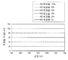
여기서, 도 1의 구성에서 각 층의 두께를 규정하고, 적, 녹, 청, 백의 각 화소의 개구율이 32%인 유기 EL 패널에서, 외광 반사의 절대 반사율과 반사광의 색을 계산하였다. 각 층의 두께는, 유리 (1㎜), 컬러 필터(RGBW) (3㎛), 수지 (3㎛), 보호층 (3㎛), 투명 전극 (0.2㎛), 유기 EL (0.3㎛), 알루미늄 (0.01㎛)으로 하였다. 또한, 개구율이란, 1서브화소에서, 실효적으로 빛나고 있는 영역의 비율을 나타내는 것으로, 예를 들면 유기 EL 패널(1000)의 윈도우나 컬러 필터의 블랙 매트릭스에 의해 개구율을 제어할 수 있다.Here, in the configuration of Fig. 1, the thickness of each layer was specified, and the absolute reflectance of external light reflection and the color of reflected light were calculated in an organic EL panel in which the aperture ratios of red, green, blue and white pixels were 32%. Each layer had a thickness of 1 mm, a
도 3은, 계산에 이용한 외광의 파장 스펙트럼을 도시하는 특성도이다. 이후에 설명하는 계산에서도, 도 3에 도시하는 파장 스펙트럼의 외광을, 참조 외광으로서 이용하는 것으로 한다. 또한, 도 4는, 적, 녹, 청의 각각의 컬러 필터(200R, 200G, 200B)의 분광 투과율을 도시한 것으로, 이후에 설명하는 계산에서도 이 값을 이용하는 것으로 한다. 도 4에서, Red-CF는 컬러 필터(200R)의 분광 투과율을, Green-CF는 컬러 필터(200G)의 분광 투과율을, Blue-CF는 컬러 필터(200B)의 분광 투과율을, 각각 나타내고 있다.3 is a characteristic diagram showing a wavelength spectrum of external light used for calculation. In the calculation described below, the external light of the wavelength spectrum shown in Fig. 3 is used as reference external light. 4 shows the spectral transmittance of each of the
도 5는, 외광의 절대 반사율과 그 내역을 계산한 결과를 도시하는 특성도이다. 또한, 도 6은, 외광과 그 반사광의 xy색도를 도시하는 특성도(chromaticity chart)이다.5 is a characteristic diagram showing the result of calculating the absolute reflectance of the external light and the details thereof. 6 is a chromaticity chart showing the xy chromaticity of the external light and the reflected light.
도 5에 도시하는 바와 같이, 외광의 절대 반사율(입사광에 대한 반사광의 비율)은 11%로 되어 있고, 그 내역은 최표면의 유리에서의 프레넬 반사의 성분이 3.5%, 적화소에 입사한 외광에서 재차 밖으로 출사된 성분이 0.7%, 녹화소에 입사한 외광에서 재차 밖으로 출사된 성분이 1.1%, 청화소에 입사한 외광에서 재차 밖으로 출사된 성분이 0.7%, 백화소에 입사한 외광에서 재차 밖으로 출사된 성분이 5.7%로 되어 있고, 외광 반사 성분의 1/2 이상이 백화소에 의한 반사광에 기인하고 있음을 알 수 있다. 또한, 도 6에 도시하는 바와 같이, xy색도도에 의하면, 반사광은 외광에 대해 황색 방향으로 시프트한다. 이것은, 유기 EL 패널(1000)의 구성에는 통상적으로 많은 단파장 대역의 성분을 흡수하는 재료가 많이 포함되어 있어서, 반사광이 청색의 보색인 황색으로 시프트하기 때문이다.As shown in Fig. 5, the absolute reflectance (the ratio of the reflected light to the incident light) of the external light is 11%, and the details thereof are 3.5% for the Fresnel reflection component in the outermost glass, 0.7% in the outside light, 1.1% in the outside light again in the external light incident on the green light, 0.7% in the outside light again in the external light incident on the blue pixel, 0.7% in the external light incident on the white pixel, It is found that the component emitted again to the outside is 5.7%, and that 1/2 or more of the external light reflection component is caused by the reflected light by the white pixel. Further, as shown in Fig. 6, according to the xy chromaticity diagram, the reflected light shifts in the yellow direction with respect to the external light. This is because the structure of the organic EL panel 1000 usually includes many materials that absorb components in a short wavelength band, and the reflected light shifts to yellow which is a complementary color to blue.
본 실시 형태는, 전술한 2번째의 반사광 성분의 저감에 초점을 맞춘 것으로, 유기 EL 패널(1000)의 내광에의 영향을 최소한으로 억제하면서, 백화소로부터의 외광 반사를 저감하고, 그 색미를 제어한다. 이를 위해, 컬러 필터(200W)(백컬러 필터)의 ND 투과율을 내림에 의해 외광의 반사율을 저감시키고, 또한, 컬러 필터(200W)에 착색을 함에 의해 반사광을 소망하는 색으로 한다.The present embodiment focuses on the reduction of the above-mentioned second reflected light component, thereby reducing external light reflection from the white pixel while suppressing the influence of the organic EL panel 1000 on the internal light to a minimum, . To this end, the ND light transmittance of the
또한, ND(Neutral Density) 투과율은, 이하와 같이 정의된다. ND 투과율이란, 가시광의 전 파장 대역에 걸쳐서 균등하게 투과율을 내리는 것을 나타내고, 색미에는 영향을 주지 않는다. 예를 들면, ND 투과율이 70%란, 가시광의 전 파장 대역(400㎚ 내지 700㎚)에 걸쳐서 투과율이 70%인 것을 의미한다.The ND (Neutral Density) transmittance is defined as follows. The ND transmittance indicates that the transmittance is uniformly lowered over the whole wavelength band of visible light, and does not affect the color appearance. For example, the ND transmittance is 70%, which means that the transmittance is 70% over the whole wavelength band of visible light (400 nm to 700 nm).
이하에서는, 순서대로 컬러 필터(200W)의 최적의 분광 특성에 관해 설명한다. 도 7에 도시하는 바와 같이, 우선, 컬러 필터(200W)의 ND 투과율을 100%, 80%, 60%, 40%, 20%, 0%의 각각으로 설정하고, 유기 EL 패널(1000)에 외광(도 3의 특성)을 조사한다. 도 8은, 이 때의, 외광의 절대 반사율을 각 ND 투과율마다 도시하는 특성도이다. 또한, 도 9는, 백화소만의 유기 EL 소자(600)를 점등한 때의 유기 EL 패널(1000)의 내광(유기 EL 내광)의 규격화 휘도를 도시하는 특성도이다. 또한, 도 10은, 외광 반사의 xy색도를 도시하는 특성도이다.In the following, the optimal spectral characteristics of the
도 8에 도시하는 바와 같이, 외광의 절대 반사율은, ND 투과율이 낮아질수록 저하되고, ND 투과율에 대해 지수함수적으로 저하된다. 한편, 도 9에 도시하는 바와 같이, 유기 EL 내광는, ND 투과율이 낮아질수록 저하되지만, ND 투과율에 대해 비례적으로 저하된다. 이것은, 전술한 바와 같이, 외광 반사는 입사시와 출사시에 컬러 필터(200)를 합계 2번 통과하는 것으로 ND 투과율의 2제곱(power) 정도로 광이 감쇠됨에 대해, 유기 EL 내광는 출사시에 컬러 필터를 1번 통과할 뿐이기 때문에, 휘도 저하는 ND 투과율의 1제곱(power)으로 억제된다. 이것은 컬러 필터(200W)(백컬러 필터)의 ND 투과율을 내림에 의해, 외광 반사를 효과적으로 저감할 수 있음을 의미한다. 따라서, 외광 반사를 저감하기 위해서는, 컬러 필터(200W)의 ND 투과율을 저하시키는 것이 알맞다. 이에 의해, 유기 EL 내광의 휘도를 희생하는 없이, 외광의 반사를 효과적으로 억제하는 것이 가능해진다.As shown in Fig. 8, the absolute reflectance of the external light decreases as the ND transmittance is lowered, and exponentially decreases with respect to the ND transmittance. On the other hand, as shown in Fig. 9, the organic EL light is lowered as the ND transmittance is lowered, but is reduced in proportion to the ND transmittance. This is because, as described above, the external light reflection attenuates light to a power of about 2 power of ND by passing the
한편, 도 10에 도시하는 바와 같이, 컬러 필터(200W)의 ND 투과율을 바꿈에 의해, 반사광의 색도(chromaticity)가 변화한다. 도 5에서 설명한 바와 같이, 외광 반사는 패널 최표면에서의 프레넬 반사와, 적, 녹, 청, 백의 각 화소로부터의 반사광의 합침이고, 각 반사광의 파장 스펙트럼은 각각 다른다. 이 때문에, ND 투과율을 바꿈에 의해 백화소로부터의 반사광량이 변화하면, 토탈의 외광 반사의 파장 스펙트럼도 변화하고, 색미가 변화한다.On the other hand, as shown in Fig. 10, the chromaticity of the reflected light changes by changing the ND transmittance of the
ND 투과율에 관해서는, 50% 이상으로 하는 것이 바람직하다. 전술한 원편광판을 부착하는 방법(특허 문헌 1, 2)에서는, 원편광판을 부착함에 의해 투과율이 저하되고, 투과율을 50% 확보하는 것은 곤란하다. 따라서, ND 투과율을 50% 이상으로 함으로써, 원편광판을 부착한 경우보다도 높은 투과율을 확보할 수 있고, 유기 EL 내광의 휘도의 저하를 억제할 수 있기 때문에, 소비 전력을 저감하는 것이 가능하다.The ND transmittance is preferably 50% or more. In the above-described method of attaching the circularly polarizing plate (
1.3. 색제(coloring agent)의 첨가에 의한 색미의 제어1.3. Control of color taste by addition of coloring agent
다음에, 컬러 필터(200W)의 ND 투과율이 80%인 경우를 예로 들어, 색제를 첨가함에 의해 외광 반사의 색미를 제어하는 방법에 관해 설명을 하다. 또한, 첨가하는 색제는, 특정한 파장 대역만의 투과율을 내리고, 그 이외의 해당하지 않는 파장 대역의 투과율은 불변으로 하는 것이다. 즉, ND 투과율에 의해 전 파장 대역의 투과율을 80%로 내리고, 색제에 의해 특정한 파장 대역만의 투과율을 내리는 것으로 한다.Next, a description will be given of a method of controlling the color taste of external light reflection by adding a coloring agent, for example, when the ND transmittance of the
ND 투과율 80%의 컬러 필터(200W)에 대표적인 6종류의 색제를 혼합하고, 컬러 필터(200W)를 도 11과 같은 분광 투과율로 한 경우를 상정한다. 각각의 컬러 필터(200W)는, (A) 400 내지 500㎚ 대역의 투과율을 내린 엷은 옐로, (B) 500 내지 600㎚ 대역의 투과율을 내린 엷은 마젠더, (C) 600 내지 700㎚ 대역의 투과율을 내린 엷은 시안, (D) 400 내지 600㎚ 대역의 투과율을 내린 엷은 적, (E) 400 내지 500㎚ 및 600 내지 700㎚ 대역의 투과율을 내린 엷은 녹, (F) 500 내지 700㎚ 대역의 투과율을 내린 엷은 청으로 한다. 또한, ND 투과율이 80%이기 때문에, (A) 내지 (F)의 어느 쪽에서도, 400㎚ 내지 700㎚ 대역에서의 투과율의 최대치는 80%로 되어 있다.It is assumed that six representative colorants are mixed in a color filter (200W) having an ND transmittance of 80%, and the color filter (200W) is set to the spectral transmittance shown in FIG. Each of the
도 12는, 이러한 분광 투과율을 갖는 컬러 필터(200W)((A) 내지 (F))를 이용한 때의 외광 반사의 xy색도를 도시하는 특성도이다. 도 12 중에는, 참조 데이터로서, 외광의 xy색도(○표시)와 ND 투과율 80%이고 무색(색제의 첨가 무)의 컬러 필터(200W)를 이용한 때의 결과(●표시)도 아울러서 나타낸다. 또한, 도 13은, 각 컬러 필터(200W)((A) 내지 (F))를 이용한 때의 외광의 절대 반사율을 도시하는 특성도이다. 도 13 중에는, 참조 데이터로서, ND 투과율 80%이고 무색(색제의 첨가 무)의 컬러 필터(200W)를 이용한 때의 결과(색제 없음)도 아울러서 나타낸다. 도 12에 도시하는 바와 같이, 컬러 필터(200W)에 색제를 첨가함에 의해, 반사광의 색을 자유롭게 제어할 수 있고, 색제의 색 방향으로 반사광의 색미가 시프트하고 있음을 알 수 있다.Fig. 12 is a characteristic chart showing the xy chromaticity of the external light reflection when the
또한, 도 13에 도시하는 바와 같이, 컬러 필터(200W)를 (B), (D), (F)와 같은 분광 투과율로 함에 의해, 외광의 절대 반사율이 저하됨을 알 수 있다. 이것은, 도 11에 도시하는 바와 같이, 색제에 의해 시감도(視感度)가 높은 550㎚ 전후의 파장 대역의 투과율이 내려가기 때문이다. 일반적인 유기 EL 패널은, 단파장(청 성분)의 광을 흡수한 재료로 구성되는 것이 많고, 외광 반사가 청색의 보색, 즉 옐로(황) 방향으로 시프트하기 쉽다는 특성이 있다. 이 때문에, 첨가하는 색제를 청색으로 함에 의해, 반사광의 색미를 청방향으로 되돌릴 수가 있고, 나아가서는 외광 반사를 효과적으로 저감하는 것이 가능하다.13, it can be seen that the absolute reflectance of the external light is reduced by setting the
도 14는, 도 11 중의 (F)의 컬러 필터(200W)를 기준(1)으로 하여, (2)→ (3)→ (4)→ (5)→ (6)의 순서로 색제(얇은 청색)의 농도를 진하게 한 6종류의 백컬러 필터를 준비하고, 각 컬러 필터(200W)((1) 내지 (6))의 파장과 투과율의 관계를 도시한 특성도이다.14 is a diagram showing the relationship between the color filter (thin blue color) and the color filter (blue color filter) in the order of (2) - (3) - (4) (1) to (6), and shows the relationship between the wavelength and the transmittance of each
도 15는, 도 14의 각 컬러 필터(200W)((1) 내지 (6))를 이용한 경우의 반사광의 xy색도를 도시하는 특성도이다. 도 15에 도시하는 바와 같이, 색제 농도를 진하다 함에 의해, 반사광의 색미는 색제의 색 방향으로 시프트하여 간다. 또한, 도 16은, 도 14의 각 백컬러 필터((1) 내지 (6))를 이용한 경우의 외광의 절대 반사율을 도시하는 특성도이다. 도 16에 도시하는 바와 같이, 색제 농도를 높게 함에 의해, 절대 반사율도 저감하여 간다.Fig. 15 is a characteristic diagram showing the xy chromaticity diagram of reflected light when each of the
1.4. 색 변화의 허용 범위에 관해1.4. Regarding the allowable range of color change
도 17은, 도 14의 각 컬러 필터(200W)((1) 내지 (6))를 이용한 경우에, 백화소만을 점등한 유기 EL 내광의 xy색도를 도시한 것이다. 도 17의 색도를 계산할 때에는, 일반적인 유기 EL의 발광 스펙트럼을 이용한다. 일반적으로, 인간의 눈으로는 색의 변화량이 Δu'v'≤0.02의 차이라면 색 변화를 허용할 수 있다고 말하여지고 있고, 디스플레이의 색 시야각 특성의 하나의 지표로서 널리 이용되고 있다. 이 때문에, 컬러 필터(200W)가 무색 투명한 때, 백화소만을 점등한 유기 EL 내광과, 컬러 필터(200W)에 색제를 첨가한 때의 백화소만을 점등한 유기 EL 내광과의 색차가 Δu'v'≤0.02를 충족시키는 것이 바람직하다.Fig. 17 shows the xy chromaticity diagram of the organic EL luminescent light in which only the white phosphors are lit when each of the
여기서, u'v'색공간이란, xy색공간을 지각 되도록 한 색공간이고, 이하의 식에서 정의되다. 또한, xy색도도는 지각 균등하지가 않다. u'v'색공간 내에서의 거리를 색차(Δu'v')라고 부르고, 예를 들면, Δu'v'가 같은 값인 것은, 인간이 보아서 느끼는 색의 차가, 거의 같은 것을 의미한다.Here, the u'v 'color space is a color space in which the xy color space is perceived, and is defined by the following expression. Also, the xy chromaticity diagram is not perceptual equivalent. The distance in the u'v 'color space is referred to as a color difference? u'v'. For example, when? u'v 'has the same value, it means that the difference in color felt by humans is almost the same.
[수식 1][Equation 1]

도 18은, 도 14의 각 컬러 필터(200W)((1) 내지 (6))를 이용한 경우에 백화소만을 점등한 유기 EL 내광과, 무색 투명한 백컬러 필터를 이용한 경우에 백화소만을 점등한 유기 EL 내광의 색차(Δu'v')를 도시하는 특성도이다. 도 18에 도시하는 바와 같이, 백컬러 필터(5)를 이용한 경우는 색차(Δu'v')가 0.02를 초과하고, 백컬러 필터(4)를 이용한 경우는 색차(Δu'v')가 0.02 이하가 된다. 따라서, 색제 농도는, 백컬러 필터((4)와 (5))의 사이 이하로 억제하는 것이 바람직하다.Fig. 18 shows a case in which only white phosphors are turned on when organic EL light with only white phosphors illuminated and a colorless transparent white color filter are used when each of the
또한, 도 19는, 도 11에 도시한 백컬러 필터(200W)((A) 내지 (F))를 베이스로 하여, 각 백컬러 필터(200W)((A) 내지 (F))의 색제 농도를 바꾼 때에, 색차(Δu'v')가 0.02 이하가 되는 분광 투과율을 도시하는 특성도이다. 보다 상세히 은, 도 19는, 백컬러 필터(200W)의 색제 농도를 바꾼 때에 백화소만을 점등한 유기 EL 내광과, 무색 투명한 백컬러 필터(200W)를 이용한 때에 백화소만을 점등한 유기 EL 내광과의 색차(Δu'v')가 0.02가 되는 분광 투과율을 나타내고 있다.19 is a graph showing the relationship between the coloring agent concentration of each of the
도 19에 도시하는 바와 같이, 각 백컬러 필터(200W)((A) 내지 (F))를 베이스에 색제 농도를 바꾼 때, 400-700㎚의 파장 대역에서 최대 투과율과 최소 투과율의 비는, (A) : 74%, (B) : 76%, (C) : 44%, (D) : 61%, (E) : 82%, (F) : 85%가 된다.19, the ratio of the maximum transmittance to the minimum transmittance in the wavelength band of 400-700 nm when the coloring agent concentration is changed on the basis of each of the back-
도 19에 도시하는 대표적인 6색의 컬러 필터(200W)((A) 내지 (F))에 관해, 400 내지 700㎚의 파장 대역에서 최대 투과율과 최소 투과율의 비의 최소치는, (C)의 44%이다. 따라서, 400 내지 700㎚의 파장 대역에서 최대 투과율과 최소 투과율의 비는, 44% 이상인 것이 바람직하다. 이에 의해, 컬러 필터(200W)를 이용한 경우의 색차(Δu'v')를 0.02이하로 할 수 있다. 이와 같이 함으로써, 백 표시는 백화소만을 점등할 뿐이면 좋기 때문에 소비 전력이 억제할 수 있고, 또한, 백 신호의 색 변화를 보정하기 위해 백화소 이외의 화소를 보조적으로 점등하였다고 하여도, 소비 전력의 증가를 최소한으로 억제할 수 있다.The minimum value of the ratio of the maximum transmittance to the minimum transmittance in the wavelength band of 400 to 700 nm is about 44 (C) in the case of the typical six-
또한, 백컬러 필터의 분광 투과율은, 유기 EL 패널(1000)의 구조나 발광 스펙트럼에도 의존하고, 상기 범위(최대 투과율과 최소 투과율의 비가 44% 이상)에 수속되지 않아도, 착색한 컬러 필터(200W)를 이용한 때의 백화소만을 점등한 유기 EL 내광과, 무색 투명한 백컬러 필터를 이용한 때의 백화소만을 점등한 유기 EL 내광과의 색차가 Δu'v'≤0.02로 수속되는 범위라면 좋다.The spectral transmittance of the white color filter also depends on the structure and the emission spectrum of the organic EL panel 1000. Even if the above range (the ratio of the maximum transmittance and the minimum transmittance is not more than 44%), ) Is used, the color difference between the organic EL light-emitting element illuminated with only the white phosphors and the organic EL light-emitting element illuminated with only the white light when the colorless transparent white color filter is used can be converged to? U'v '?
이상 설명한 바와 같이 제1의 실시 형태에 의하면, 유기 EL 패널(1000)의 내광의 휘도와 색미에의 영향을 최소한으로 억제하면서, 외광 반사의 절대 반사율과 색미를 효과적으로 제어하는 것이 가능해진다.As described above, according to the first embodiment, it is possible to effectively control the absolute reflectance and color taste of the external light reflection while minimizing the influence of the organic EL panel 1000 on the brightness and color appearance of the internal light.
<2. 제2의 실시 형태><2. Second Embodiment>
다음에, 본 개시된 제2의 실시 형태에 관해 설명한다. 제2의 실시 형태는, 유기 EL 패널(1000)의 백화소의 개구율을 작게 함에 의해, 백화소의 휘도를 조정하는 것이다. 이에 의해, 외광 반사율을 저감시키는 것이 가능하다.Next, a second embodiment of the present invention will be described. The second embodiment adjusts the luminance of white pixels by decreasing the aperture ratio of the white pixels of the organic EL panel 1000. [ Thereby, it is possible to reduce the external light reflectance.
도 20은, 무색 투명(ND 투과율 100%)한 백화소에서, 적화소, 녹화소, 청화소의 개구율은 32%로 고정하고, 백화소의 개구율비를 100%, 80%, 60%, 40%, 20%, 0%로 하였을 때의 외광 반사의 xy색도를 도시하는 특성도이다. 마찬가지로, 도 21은, 무색 투명(ND 투과율 100%)의 백화소에서, 적화소, 녹화소, 청화소의 개구율은 32%로 고정하고, 백화소의 개구율비를 100%, 80%, 60%, 40%, 20%, 0%로 하였을 때의 절대 반사율을 도시하는 특성도이다. 여기서, 개구율비란 적화소, 녹화소, 청화소의 개구율(32%)과의 비를 나타내는 것으로, 예를 들면, 적화소, 녹화소, 청화소의 개구율이 32%인 경우에 있어서, 개구율비 50%란 백화소의 개구율이 16%인 것을 의미한다. 도 21에 도시하는 바와 같이, 백화소만 개구율을 내림에 의해 외광의 반사율을 억제할 수 있다. 한편, 도 20에 도시하는 바와 같이, 백화소만 개구율을 변화시킴에 의해, 백화소로부터의 반사광량이 변화하기 때문에, 외광 반사의 색미도 변화한다. 단, 제1의 실시 형태에서 나타낸 바와 같이, 적당한 색제를 가함에 의해 반사광의 색을 제어할 수 있다.20 shows that the aperture ratios of red pixels, green pixels, and blue pixels are fixed at 32%, white pixels have aperture ratio ratios of 100%, 80%, 60%, and 40%, respectively, , 20%, and 0%, respectively. Similarly, FIG. 21 shows that the aperture ratios of red pixels, green pixels, and blue pixels are fixed at 32% in white pixels of colorless transparency (ND transmittance of 100%) and aperture ratio of white pixels is 100%, 80% 40%, 20%, and 0%, respectively. For example, when the aperture ratio of the red pixel, the green pixel, and the blue pixel is 32%, the ratio of the aperture ratio (50%) to the aperture ratio % Means that the aperture ratio of white pigments is 16%. As shown in Fig. 21, the reflectance of external light can be suppressed by lowering the aperture ratio of only white pigments. On the other hand, as shown in Fig. 20, since the amount of reflected light from the white pixel changes by changing the aperture ratio of only white pigments, the color of the external light reflection also changes. However, as shown in the first embodiment, the color of the reflected light can be controlled by adding a suitable coloring agent.
여기서, 백화소의 개구율을 적화소, 녹화소, 청화소의 개구율(32%)보다도 작게 하여 개구율비를 100% 이하로 하고, 또한 컬러 필터(200W)의 ND 투과율을 내린 때를 상정한다. 도 22는, 백화소의 개구율비와 ND 투과율에 대한 외광의 절대 반사율(종축)을 나타냈던 것이다. 도 22에 도시하는 바와 같이, 백화소의 개구율비와 ND 투과율을 최적으로 변화시킴에 의해, 소망하는 절대 반사율을 실현할 수 있음을 알 수 있다.Here, it is assumed that the aperture ratio of the white pixel is made smaller than the aperture ratio (32%) of the red pixel, green pixel, and blue pixel, and the ND transmittance of the
도 23은, 백화소의 개구율비를 80%로 하고, 도 11에 도시한 백컬러 필터(200W)(F)(ND 투과율 80%)를 이용한 때의 외광 반사의 xy색도를 도시하는 특성도이다. 도 23에서, ●표시는 백컬러 필터(200W)(F)에 의한 외광 반사의 특성을 나타내고 있고, ▲표시는 백컬러 필터(200W)(F)에 색제를 첨가하여 착색한 경우를 나타내고 있다. 도 23에 도시하는 바와 같이, 백화소의 개구율비 및 ND 투과율을 바꾼 경우에도, 백컬러 필터(200W)에 착색을 함에 의해 외광 반사의 색미의 제어가 가능해진다.23 is a characteristic diagram showing the xy chromaticity of the external light reflection when the
또한, 본 실시 형태에서는, 적화소, 녹화소, 청화소의 화소 개구율을 32%로 하였지만, 화소 개구율은 32%로 한정되는 것이 아니다.In the present embodiment, the pixel aperture ratio of the red pixel, the green pixel, and the blue pixel is 32%, but the pixel aperture ratio is not limited to 32%.
이상 설명한 바와 같이 제2의 실시 형태에 의하면, 적화소, 녹화소, 청화소의 개구율에 대해 백화소의 개구율을 저하시킴으로써, 외광 반사율을 저감하는 것이 가능해진다. 또한, 이 경우에도, 백컬러 필터(200W)에 착색을 함에 의해 외광 반사의 색미의 제어가 가능해진다.As described above, according to the second embodiment, it is possible to reduce the external light reflectance by lowering the aperture ratio of white pixels with respect to the aperture ratios of red pixels, green pixels, and blue pixels. Also in this case, coloring of the back-
<3. 제3의 실시 형태><3. Third Embodiment>
다음에, 본 개시된 제3의 실시 형태에 관해 설명한다. 제3의 실시 형태에서는, 백화소의 개구율비를 올리고, 또한 ND 투과율을 내림으로써, 외광 반사를 저감한다. 도 24는, 도 22와 마찬가지로 개구율비, ND 투과율, 외광 반사율의 관계를 도시하는 특성도이다. 도 24는, 백화소의 개구율비를 100%, 120%, 140%, 160%, 180%, 200%로 하였을 때의 외광 반사의 절대 반사율을 나타내고 있다.Next, a third embodiment of the present invention will be described. In the third embodiment, external light reflection is reduced by increasing the aperture ratio of white pigments and lowering the ND transmittance. 24 is a characteristic diagram showing the relationship between the aperture ratio, the ND transmittance, and the external light reflectance as in Fig. Fig. 24 shows the absolute reflectance of external light reflection when the aperture ratio of white pigments is set to 100%, 120%, 140%, 160%, 180%, and 200%.
이와 같이, 적화소, 녹화소, 청화소의 개구율을 고정하고, 백화소의 개구율비만을 올리고, ND 투과율을 내림에 의해서도 외광 반사율을 억제할 수 있다. 이 경우에도, 제2의 실시 형태와 마찬가지로, 개구율비 및 ND 투과율을 바꾼 때에, 백컬러 필터(200W)에 착색을 함에 의해 반사광의 색미의 제어가 가능하다.Thus, it is possible to fix the aperture ratio of the red pixel, the green pixel, and the blue pixel, to increase only the aperture ratio of white pigments, and to suppress the external light reflectance even by lowering the ND transmittance. In this case as well, similarly to the second embodiment, the color tone of the reflected light can be controlled by coloring the
또한, 백화소뿐만 아니라, 아울러서 적, 녹, 청화소의 개구율을 임의로 함으로써, 외광의 색미 및 반사율을 조정하여도 좋다. 예를 들면, 외광 반사의 적미를 억제하고 싶은 경우, 적화소의 개구율을 상대적으로 줄이는 등으로, 색미의 제어에 연결하여도 좋다.Further, the coloring property of the external light and the reflectance may be adjusted not only by the white pixel but also by arbitrarily setting the aperture ratios of the red, green and blue pixels. For example, when it is desired to suppress the redness of the external light reflection, it may be connected to the control of the color taste by relatively reducing the aperture ratio of the red pixel.
<4. 제4의 실시 형태><4. Fourth Embodiment >
다음에, 본 개시된 제4의 실시 형태에 관해 설명한다. 제4의 실시 형태는, 디바이스의 구성이나 재질에 응하여 외광 반사의 색미를 최적으로 제어하는 것이다.Next, a fourth embodiment of the present invention will be described. The fourth embodiment optimally controls the color taste of the external light reflection in response to the configuration and material of the device.
제1의 실시 형태에서 설명한 바와 같이, 외광 반사의 색미는 다양한 색으로 제어할 수 있는데, 예를 들면, 디바이스의 구성이나 재질이 변한 때에도 유효하다. 도 26은, 외광 반사의 xy색도를 도시하는 특성도로서, 외광(○표시), 금속 전극(700)의 재료가 알루미늄(Al)인 경우의 외광 반사(●표시), 금속 전극(700)의 재료가 구리(Cu)인 경우의 외광 반사(▲표시), 금속 전극(700)의 재료가 구리(Cu)인 경우로서 색을 제어한 경우의 외광 반사(■표시)의 xy색도를 도시하는 특성도이다. 예를 들면 금속 전극(700)의 재료가 알루미늄(Al)으로부터 구리(Cu)로 변한 경우를 상정하면, 도 26과 같이 그 외광 반사의 색은 적 방향으로 시프트한다(▲표시). 이 경우, 백컬러 필터에 착색을 하여 도 25에 도시하는 바와 같은 분광 투과율로 함에 의해, 반사광의 색미를, 금속 전극(700)의 재료가 알루미늄(Al)의 경우의 색미와 가깝게 할 수 있다(■표시).As described in the first embodiment, the color appearance of the external light reflection can be controlled in various colors, for example, even when the configuration or material of the device is changed. 26 is a diagram showing the xy chromaticity diagram of the external light reflection, in which the external light (? Display), the external light reflection (? Display) when the material of the
이와 같이, 디바이스의 구성이나 재질에 의해, 외광 반사의 색이 변한 때에도, 컬러 필터(200W)에 색제를 첨가함에 의해, 소망하는 색의 반사광을 얻는 것이 가능하다.Thus, even when the color of the external light reflection changes due to the configuration or the material of the device, it is possible to obtain reflected light of a desired color by adding a coloring agent to the
<5. 제5의 실시 형태><5. Fifth Embodiment>
도 27은, 유기 EL 패널(1000)을 구비하는 표시 장치(2000)의 회로 구성을 도시하는 모식도이다. 표시 장치(2000)는, 구동 패널(1100)상에, 매트릭스형상으로 배설된 복수의 적화소(10R), 녹화소(10G), 청화소(10B)와, 이들의 화소(10R, 10G, 10B)를 구동하기 위한 각종 구동 회로가 형성된 것이다. 화소(10R, 10G, 10B)는 각각, 적색(R : Red), 녹색(G : Green) 및 청색(B : Blue)의 색광을 발한 유기 EL 소자(600)를 갖고 구성된다. 이들 3개의 화소(10R, 10G, 10B)를 하나의 픽셀로 하여, 복수의 픽셀에 의해 유기 EL 패널(1000)로 이루어지는 표시 영역(2200)이 구성되어 있다. 구동 패널(1100)상에는, 구동 회로로서, 예를 들면 영상 표시용의 드라이버인 신호선 구동 회로(2300) 및 주사선 구동 회로(2400)와, 화소 구동 회로(2500)가 배설되어 있다. 이 구동 패널(1100)에는, 도시하지 않은 밀봉 패널이 접합되고, 이 밀봉 패널에 의해 화소(10R, 10G, 10B) 및 상기 구동 회로가 밀봉되어 있다.27 is a schematic diagram showing a circuit configuration of a
도 28은, 화소 구동 회로(2500)의 등가 회로도이다. 화소 구동 회로(2500)는, 상기 박막 트랜지스터로서, 트랜지스터(Tr, Tr2)가 배설된 액티브형의 구동 회로이다. 트랜지스터(Tr, Tr2)의 사이에는 커패시터(Cs)가 마련되고, 제1의 전원 라인(Vcc) 및 제2의 전원 라인(GND)의 사이에서, 화소(10R)(또는 화소(10G, 10B))가 트랜지스터(Tr1)에 직렬로 접속되어 있다. 이와 같은 화소 구동 회로(2500)에서는, 열방향으로 신호선(2600A)이 복수 배치되고, 행방향으로 주사선(2700A)이 복수 배치되어 있다. 각 신호선(2600A)은, 신호선 구동 회로(2300)에 접속되고, 이 신호선 구동 회로(2300)로부터 신호선(2600A)을 통하여 트랜지스터(Tr2)의 소스 전극에 화상 신호가 공급되도록 되어 있다. 각 주사선(2700A)은 주사선 구동 회로(2400)에 접속되고, 이 주사선 구동 회로(2400)로부터 주사선(2700A)을 통하여 트랜지스터(Tr2)의 게이트 전극에 주사 신호가 순차적으로 공급되도록 되어 있다. 이와 같은 표시 장치(2000)는, 예를 들면 텔레비전 장치, 디지털 카메라, 노트형 퍼스널 컴퓨터, 비디오 카메라, 휴대 전화(모바일 기기) 등의 전자 기기에 탑재할 수 있다.Fig. 28 is an equivalent circuit diagram of the
이상, 첨부 도면을 참조하면서 본 개시된 알맞은 실시 형태에 관해 상세히 설명하였지만, 본 개시된 기술적 범위는 이러한 예로 한정되지 않는다. 본 개시된 기술 분야에서의 통상의 지식을 갖는 자라면, 특허청구의 범위에 기재된 기술적 사상의 범주 내에서, 각종의 변경예 또는 수정예에 상도할 수 있음은 분명하고, 이들에 대해서도, 당연히 본 개시된 기술적 범위에 속하는 것이라고 이해된다.While the preferred embodiments of the present invention have been described in detail with reference to the accompanying drawings, the disclosed technical scope is not limited to these examples. It will be understood by those skilled in the art that various changes and modifications may be made without departing from the scope of the invention as defined in the appended claims. It is understood to belong to the technical scope.
또한, 본 명세서에 기재된 효과는, 어디까지나 설명적 또는 예시적인 것이고 한정적이 아니다. 즉, 본 개시에 관한 기술은, 상기한 효과와 함께, 또는 상기한 효과에 대신하여, 본 명세서의 기재로부터 당업자에게는 분명한 다른 효과를 이룰 수 있다.Further, the effects described in the present specification are only illustrative or exemplary and are not limitative. That is, the technique relating to the present disclosure may achieve other obvious effects to those skilled in the art from the description of the present specification, together with or instead of the above effects.
또한, 이하와 같은 구성도 본 개시된 기술적 범위에 속한다.In addition, the following configurations are also within the technical scope of the present disclosure.
(1) 각 색의 화소에 대응하는 유기 EL 발광 소자와,(1) an organic EL light emitting element corresponding to a pixel of each color,
백화소에 대응하는 백컬러 필터를 구비하고,And a white color filter corresponding to a white pixel,
상기 백컬러 필터의 투과율은, 가시광의 전 파장 대역에 걸쳐서 균등한 ND 투과율을 베이스로 하고, 상기 가시광의 전 파장 대역 중, 특정한 파장 대역의 투과율이 상기 ND 투과율보다도 저하되어 있는, 표시 장치.Wherein the transmittance of the white color filter is based on an ND transmittance which is uniform over an entire wavelength band of visible light and the transmittance of a specific wavelength band among the whole wavelength band of the visible light is lower than the ND transmittance.
(2) 상기 백컬러 필터는, 색제의 첨가에 의해 상기 특정한 파장 대역의 투과율이 상기 ND 투과율보다도 저하되어 있는, 상기 (1)에 기재된 표시 장치.(2) The display device according to (1), wherein the white color filter has a transmittance lower than the ND transmittance by the addition of a coloring agent in the specific wavelength band.
(3) 상기 ND 투과율이 50% 이상인, 상기 (1)에 기재된 표시 장치.(3) The display device according to (1), wherein the ND transmittance is 50% or more.
(4) 상기 가시광의 전 파장 대역은, 400㎚ 내지 700㎚인, 상기 (1)에 기재된 표시 장치.(4) The display device according to (1), wherein the entire wavelength band of the visible light is 400 nm to 700 nm.
(5) 상기 백컬러 필터는, 적, 녹, 청 또는 그들의 보색으로 착색되어 있는, 상기 (1)에 기재된 표시 장치.(5) The display device according to (1), wherein the white color filter is colored with red, green, blue or complementary colors thereof.
(6) 상기 백컬러 필터는, 가시광의 전 파장 대역에서 분광 투과율의 최대치에 대한 최소치의 비가 0.44 이상인, 상기 (1)에 기재된 표시 장치.(6) The display device according to (1), wherein the white color filter has a ratio of a minimum value to a maximum value of a spectral transmittance in a full wavelength band of visible light of 0.44 or more.
(7) 상기 유기 EL 발광 소자로부터 출사하여 상기 백컬러 필터를 투과한 유기 EL 내광과, 가시광의 전 파장 대역에 걸쳐서 균등한 ND 투과율을 갖는 무색 투명한 백컬러 필터를 투과한 유기 EL 내광과의 색차(Δu'v')가 0.02 이하인, 상기 (1)에 기재된 표시 장치.(7) The organic EL light emitting device according to any one of the above items (1) to (5), wherein the organic EL inner light emitted from the organic EL light emitting element and transmitted through the white color filter and the colorless transparent white color filter having a uniform ND transmittance (? U'v ') is 0.02 or less.
(8) 상기 백컬러 필터에 대응하는 백화소의 개구율이 적화소, 녹화소, 청화소의 개구율과 다른, 상기 (1)에 기재된 표시 장치.(8) The display device according to (1), wherein an aperture ratio of a white pixel corresponding to the white color filter is different from an aperture ratio of a red pixel, a green pixel, and a blue pixel.
(9) 상기 백컬러 필터에 대응하는 백화소의 개구율이 적화소, 녹화소, 청화소의 개구율보다도 작은, 상기 (8)에 기재된 표시 장치.(9) The display device according to (8), wherein an aperture ratio of a white pixel corresponding to the white color filter is smaller than an aperture ratio of a pixel, a green pixel, and a blue pixel.
(10) 상기 백컬러 필터에 대응하는 백화소의 개구율이 적화소, 녹화소, 청화소의 개구율보다도 큰, 상기 (8)에 기재된 표시 장치.(10) The display device according to (8), wherein an aperture ratio of a white pixel corresponding to the white color filter is larger than an aperture ratio of a red pixel, a green pixel, and a blue pixel.
(11) 각 색의 화소에 대응하는 유기 EL 발광 소자와, 백화소에 대응하는 백컬러 필터를 구비하고, 상기 백컬러 필터는, 가시광의 전 파장 대역에 걸쳐서 균등한 ND 투과율을 베이스로 하고, 상기 가시광의 전 파장 대역 중, 특정한 파장 대역의 투과율이 상기 ND 투과율보다도 저하되어 있는, 표시 장치를 탑재한, 전자 기기.(11) An organic EL light emitting element corresponding to a pixel of each color, and a white color filter corresponding to a white pixel, wherein the white color filter is based on an ND transmittance which is uniform over an entire wavelength band of visible light, Wherein a transmittance of a specific wavelength band among the whole wavelength band of the visible light is lower than the ND transmittance.
(12) 상기 백컬러 필터는, 색제의 첨가에 의해 상기 특정한 파장 대역의 투과율이 상기 ND 투과율보다도 저하되어 있는, 상기 (11)에 기재된 전자 기기.(12) The electronic device according to (11), wherein the white color filter has a transmittance lower than the ND transmittance by the addition of a coloring agent in the specific wavelength band.
(13) 상기 ND 투과율이 50% 이상인, 상기 (11)에 기재된 전자 기기.(13) The electronic device according to (11), wherein the ND transmittance is 50% or more.
(14) 상기 가시광의 전 파장 대역은, 400㎚ 내지 700㎚인, 상기 (11)에 기재된 전자 기기.(14) The electronic device according to (11), wherein the whole wavelength band of the visible light is 400 nm to 700 nm.
(15) 상기 백컬러 필터는, 적, 녹, 청 또는 그들의 보색으로 착색되어 있는, 상기 (11)에 기재된 전자 기기.(15) The electronic device according to (11), wherein the white color filter is colored with red, green, blue or a complementary color thereof.
(16) 상기 백컬러 필터는, 가시광의 전 파장 대역에서 분광 투과율의 최대치에 대한 최소치의 비가 0.44 이상인, 상기 (11)에 기재된 전자 기기.(16) The electronic device according to (11), wherein the white color filter has a ratio of a minimum value to a maximum value of spectral transmittance in a full wavelength band of visible light of 0.44 or more.
(17) 상기 유기 EL 발광 소자로부터 출사하여 상기 백컬러 필터를 투과한 유기 EL 내광과, 가시광의 전 파장 대역에 걸쳐서 균등한 ND 투과율을 갖는 무색 투명한 백컬러 필터를 투과한 유기 EL 내광과의 색차(Δu'v')가 0.02 이하인, 상기 (11)에 기재된 전자 기기.(17) An organic EL light emitting element which emits light from the organic EL light emitting element and has passed through the white color filter, and a color difference (color difference) with the organic EL light which has passed through a colorless transparent white color filter having a uniform ND transmittance over the entire wavelength band of visible light (? U'v ') is 0.02 or less.
(18) 상기 백컬러 필터에 대응하는 백화소의 개구율이 적화소, 녹화소, 청화소의 개구율과 다른, 상기 (11)에 기재된 전자 기기.(18) The electronic apparatus according to (11), wherein an aperture ratio of a white pixel corresponding to the white color filter is different from an aperture ratio of a red pixel, a green pixel, and a blue pixel.
(19) 상기 백컬러 필터에 대응하는 백화소의 개구율이 적화소, 녹화소, 청화소의 개구율보다도 작은, 상기 (18)에 기재된 전자 기기.(19) The electronic apparatus according to (18), wherein an aperture ratio of a white pixel corresponding to the white color filter is smaller than an aperture ratio of a pixel, a green pixel, and a blue pixel.
(20) 상기 백컬러 필터에 대응하는 백화소의 개구율이 적화소, 녹화소, 청화소의 개구율보다도 큰, 상기 (18)에 기재된 전자 기기.
(20) The electronic device according to (18), wherein an aperture ratio of a white pixel corresponding to the white color filter is larger than an aperture ratio of a pixel, a green pixel, and a blue pixel.
600 : 유기 EL 소자
200W :백컬러 필터
1000 :유기 EL 패널600: organic EL device
200W: Back Color Filter
1000: organic EL panel
Claims (20)
백화소에 대응하는 백컬러 필터를 가지며,
상기 백컬러 필터의 투과율은, 가시광의 전 파장 대역에 걸쳐서 균등한 ND 투과율을 베이스로 하고, 상기 가시광의 전 파장 대역 중, 특정한 파장 대역의 투과율이 상기 ND 투과율보다도 저하되어 있는 것을 특징으로 하는 표시 장치.A light emitting element corresponding to a pixel of each color,
A white color filter corresponding to a white pixel,
Wherein the transmittance of the white color filter is based on ND transmittance which is uniform over the whole wavelength band of visible light and the transmittance of the specific wavelength band among the whole wavelength band of the visible light is lower than the ND transmittance Device.
상기 백컬러 필터는, 색제의 첨가에 의해 상기 특정한 파장 대역의 투과율이 상기 ND 투과율보다도 저하되어 있는 것을 특징으로 하는 표시 장치.The method according to claim 1,
Wherein the white color filter has a transmittance lower than the ND transmittance in the specific wavelength band by adding a coloring agent.
상기 ND 투과율이 50% 이상인 것을 특징으로 하는 표시 장치.The method according to claim 1,
Wherein the ND transmittance is 50% or more.
상기 가시광의 전 파장 대역은, 400㎚ 내지 700㎚인 것을 특징으로 하는 표시 장치.The method according to claim 1,
Wherein the whole wavelength band of the visible light is 400 nm to 700 nm.
상기 백컬러 필터는, 적, 녹, 청 또는 그들의 보색으로 착색되어 있는 것을 특징으로 하는 표시 장치.The method according to claim 1,
Wherein the white color filter is colored with red, green, blue or complementary colors thereof.
상기 백컬러 필터는, 가시광의 전 파장 대역에서 분광 투과율의 최대치에 대한 최소치의 비가 0.44 이상인 것을 특징으로 하는 표시 장치.The method according to claim 1,
Wherein the white color filter has a ratio of a minimum value to a maximum value of a spectral transmittance in a full wavelength band of visible light of 0.44 or more.
상기 유기 EL 발광 소자로부터 출사하여 상기 백컬러 필터를 투과한 유기 EL 내광과, 가시광의 전 파장 대역에 걸쳐서 균등한 ND 투과율을 갖는 무색 투명한 백컬러 필터를 투과한 유기 EL 내광과의 색차(Δu'v')가 0.02 이하인 것을 특징으로 하는 표시 장치.The method according to claim 1,
(? U ') between the organic EL inner light emitted from the organic EL light emitting element and transmitted through the white color filter and the organic EL inner light transmitted through a colorless transparent white color filter having a uniform ND transmittance over the entire wavelength band of visible light, v ') is 0.02 or less.
상기 백컬러 필터에 대응하는 백화소의 개구율이 적화소, 녹화소, 청화소의 개구율과 다른 것을 특징으로 하는 표시 장치.The method according to claim 1,
And the aperture ratio of the white pixel corresponding to the white color filter is different from the aperture ratio of the red pixel, the green pixel, and the blue pixel.
상기 백컬러 필터에 대응하는 백화소의 개구율이 적화소, 녹화소, 청화소의 개구율보다도 작은 것을 특징으로 하는 표시 장치.9. The method of claim 8,
Wherein an aperture ratio of a white pixel corresponding to the white color filter is smaller than an aperture ratio of a pixel, a green pixel, and a blue pixel.
상기 백컬러 필터에 대응하는 백화소의 개구율이 적화소, 녹화소, 청화소의 개구율보다도 큰 것을 특징으로 하는 표시 장치.9. The method of claim 8,
Wherein an aperture ratio of a white pixel corresponding to the white color filter is larger than an aperture ratio of a red pixel, a green pixel, and a blue pixel.
상기 백컬러 필터는, 색제의 첨가에 의해 상기 특정한 파장 대역의 투과율이 상기 ND 투과율보다도 저하되어 있는 것을 특징으로 하는 전자 기기.12. The method of claim 11,
Wherein the white color filter has a transmittance lower than the ND transmittance in the specific wavelength band by the addition of a coloring agent.
상기 ND 투과율이 50% 이상인 것을 특징으로 하는 전자 기기.12. The method of claim 11,
Wherein the ND transmittance is 50% or more.
상기 가시광의 전 파장 대역은, 400㎚ 내지 700㎚인 것을 특징으로 하는 전자 기기.12. The method of claim 11,
Wherein an entire wavelength band of the visible light is 400 nm to 700 nm.
상기 백컬러 필터는, 적, 녹, 청 또는 그들의 보색으로 착색되어 있는 것을 특징으로 하는 전자 기기.12. The method of claim 11,
Wherein the back-color filter is colored with red, green, blue or a complementary color thereof.
상기 백컬러 필터는, 가시광의 전 파장 대역에서 분광 투과율의 최대치에 대한 최소치의 비가 0.44 이상인 것을 특징으로 하는 전자 기기.12. The method of claim 11,
Wherein the white color filter has a ratio of a minimum value to a maximum value of spectral transmittance in a full wavelength band of visible light of 0.44 or more.
상기 유기 EL 발광 소자로부터 출사하여 상기 백컬러 필터를 투과한 유기 EL 내광과, 가시광의 전 파장 대역에 걸쳐서 균등한 ND 투과율을 갖는 무색 투명한 백컬러 필터를 투과한 유기 EL 내광과의 색차(Δu'v')가 0.02 이하인 것을 특징으로 하는 전자 기기.12. The method of claim 11,
(? U ') between the organic EL inner light emitted from the organic EL light emitting element and transmitted through the white color filter and the organic EL inner light transmitted through a colorless transparent white color filter having a uniform ND transmittance over the entire wavelength band of visible light, v ') is 0.02 or less.
상기 백컬러 필터에 대응하는 백화소의 개구율이 적화소, 녹화소, 청화소의 개구율과 다른 전자 기기.12. The method of claim 11,
Wherein an aperture ratio of a white pixel corresponding to the white color filter is different from an aperture ratio of a pixel, a green pixel, and a blue pixel.
상기 백컬러 필터에 대응하는 백화소의 개구율이 적화소, 녹화소, 청화소의 개구율보다도 작은 것을 특징으로 하는 전자 기기.19. The method of claim 18,
Wherein an aperture ratio of a white pixel corresponding to the white color filter is smaller than an aperture ratio of a pixel, a green pixel, and a blue pixel.
상기 백컬러 필터에 대응하는 백화소의 개구율이 적화소, 녹화소, 청화소의 개구율보다도 큰 것을 특징으로 하는 전자 기기.19. The method of claim 18,
Wherein an aperture ratio of a white pixel corresponding to the white color filter is larger than an aperture ratio of a pixel, a green pixel, and a blue pixel.
Applications Claiming Priority (2)
| Application Number | Priority Date | Filing Date | Title |
|---|---|---|---|
| JP2013168883A JP2015037062A (en) | 2013-08-15 | 2013-08-15 | Display device and electronic apparatus |
| JPJP-P-2013-168883 | 2013-08-15 |
Publications (2)
| Publication Number | Publication Date |
|---|---|
| KR20150020504A true KR20150020504A (en) | 2015-02-26 |
| KR102292750B1 KR102292750B1 (en) | 2021-08-25 |
Family
ID=52466194
Family Applications (1)
| Application Number | Title | Priority Date | Filing Date |
|---|---|---|---|
| KR1020140097101A Active KR102292750B1 (en) | 2013-08-15 | 2014-07-30 | Display device and electronic device |
Country Status (5)
| Country | Link |
|---|---|
| US (1) | US9368557B2 (en) |
| JP (1) | JP2015037062A (en) |
| KR (1) | KR102292750B1 (en) |
| CN (2) | CN104377221B (en) |
| TW (1) | TWI636284B (en) |
Cited By (1)
| Publication number | Priority date | Publication date | Assignee | Title |
|---|---|---|---|---|
| US12588402B2 (en) | 2021-09-08 | 2026-03-24 | Samsung Display Co., Ltd. | Electronic device |
Families Citing this family (8)
| Publication number | Priority date | Publication date | Assignee | Title |
|---|---|---|---|---|
| CN112992992A (en) * | 2014-10-01 | 2021-06-18 | 索尼公司 | Display device and electronic apparatus |
| KR102572407B1 (en) | 2015-07-22 | 2023-08-30 | 엘지디스플레이 주식회사 | Thin Film Transistor Array Substrate And Organic Light Emitting Diode Display Device Including The Same |
| JP6734674B2 (en) * | 2016-03-23 | 2020-08-05 | パイオニア株式会社 | Light emitting device |
| US11156826B2 (en) * | 2019-12-11 | 2021-10-26 | Visera Technologies Company Limited | Optical devices |
| WO2021181224A1 (en) * | 2020-03-09 | 2021-09-16 | 3M Innovative Properties Company | Reflective polarizer and display system |
| CN114167639B (en) * | 2020-09-11 | 2024-02-27 | 成都辰显光电有限公司 | Display panel, display device and control method of display panel |
| CN115734686A (en) * | 2021-08-26 | 2023-03-03 | 京东方科技集团股份有限公司 | Display panel and display device |
| CN115061322B (en) * | 2022-06-17 | 2023-10-24 | 云谷(固安)科技有限公司 | Display screen, display screen manufacturing method and electronic equipment |
Citations (8)
| Publication number | Priority date | Publication date | Assignee | Title |
|---|---|---|---|---|
| JPH1048752A (en) | 1996-08-02 | 1998-02-20 | Toppan Printing Co Ltd | Lenticular sheet for transmission screen |
| KR20100068074A (en) * | 2008-12-12 | 2010-06-22 | 삼성전자주식회사 | Organic light emitting devicce |
| JP2010243769A (en) | 2009-04-06 | 2010-10-28 | Toppan Printing Co Ltd | Circularly polarizing plate and organic EL display device |
| KR20110063086A (en) * | 2009-12-04 | 2011-06-10 | 삼성모바일디스플레이주식회사 | Organic light emitting device |
| KR20110093451A (en) * | 2010-02-12 | 2011-08-18 | 삼성모바일디스플레이주식회사 | Organic light emitting display device |
| KR20120012940A (en) * | 2010-08-03 | 2012-02-13 | 엘지디스플레이 주식회사 | Organic light emitting device |
| WO2013051428A1 (en) * | 2011-10-03 | 2013-04-11 | ソニー株式会社 | Display device and electronic device |
| JP2013097287A (en) | 2011-11-04 | 2013-05-20 | Dainippon Printing Co Ltd | Color filter for organic electroluminescence display device, and organic electroluminescence display device |
Family Cites Families (5)
| Publication number | Priority date | Publication date | Assignee | Title |
|---|---|---|---|---|
| JP2005317507A (en) * | 2004-03-30 | 2005-11-10 | Sanyo Electric Co Ltd | Organic electroluminescence device |
| US7294959B2 (en) * | 2005-10-24 | 2007-11-13 | Eastman Kodak Company | OLED device having improved contrast |
| JP2012199231A (en) * | 2011-03-04 | 2012-10-18 | Semiconductor Energy Lab Co Ltd | Display device |
| US20140111748A1 (en) * | 2011-06-07 | 2014-04-24 | Kozo Nakamura | Display device |
| TWI538193B (en) * | 2014-02-19 | 2016-06-11 | 友達光電股份有限公司 | Organic light emitting device and fabricating method thereof |
-
2013
- 2013-08-15 JP JP2013168883A patent/JP2015037062A/en active Pending
-
2014
- 2014-07-17 TW TW103124606A patent/TWI636284B/en not_active IP Right Cessation
- 2014-07-30 KR KR1020140097101A patent/KR102292750B1/en active Active
- 2014-08-07 CN CN201410386855.2A patent/CN104377221B/en active Active
- 2014-08-07 CN CN201910481110.7A patent/CN110350100B/en active Active
- 2014-08-07 US US14/453,713 patent/US9368557B2/en active Active
Patent Citations (8)
| Publication number | Priority date | Publication date | Assignee | Title |
|---|---|---|---|---|
| JPH1048752A (en) | 1996-08-02 | 1998-02-20 | Toppan Printing Co Ltd | Lenticular sheet for transmission screen |
| KR20100068074A (en) * | 2008-12-12 | 2010-06-22 | 삼성전자주식회사 | Organic light emitting devicce |
| JP2010243769A (en) | 2009-04-06 | 2010-10-28 | Toppan Printing Co Ltd | Circularly polarizing plate and organic EL display device |
| KR20110063086A (en) * | 2009-12-04 | 2011-06-10 | 삼성모바일디스플레이주식회사 | Organic light emitting device |
| KR20110093451A (en) * | 2010-02-12 | 2011-08-18 | 삼성모바일디스플레이주식회사 | Organic light emitting display device |
| KR20120012940A (en) * | 2010-08-03 | 2012-02-13 | 엘지디스플레이 주식회사 | Organic light emitting device |
| WO2013051428A1 (en) * | 2011-10-03 | 2013-04-11 | ソニー株式会社 | Display device and electronic device |
| JP2013097287A (en) | 2011-11-04 | 2013-05-20 | Dainippon Printing Co Ltd | Color filter for organic electroluminescence display device, and organic electroluminescence display device |
Cited By (1)
| Publication number | Priority date | Publication date | Assignee | Title |
|---|---|---|---|---|
| US12588402B2 (en) | 2021-09-08 | 2026-03-24 | Samsung Display Co., Ltd. | Electronic device |
Also Published As
| Publication number | Publication date |
|---|---|
| CN110350100B (en) | 2022-08-16 |
| JP2015037062A (en) | 2015-02-23 |
| TW201506460A (en) | 2015-02-16 |
| KR102292750B1 (en) | 2021-08-25 |
| CN110350100A (en) | 2019-10-18 |
| TWI636284B (en) | 2018-09-21 |
| US9368557B2 (en) | 2016-06-14 |
| US20150048345A1 (en) | 2015-02-19 |
| CN104377221A (en) | 2015-02-25 |
| CN104377221B (en) | 2019-06-07 |
Similar Documents
| Publication | Publication Date | Title |
|---|---|---|
| KR102292750B1 (en) | Display device and electronic device | |
| US7916245B2 (en) | Display device | |
| US10306729B2 (en) | Display with ambient-adaptive backlight color | |
| TWI503812B (en) | Display | |
| US7990499B2 (en) | Display device | |
| US7952662B2 (en) | Transflective display device | |
| JP4120674B2 (en) | Electro-optical device and electronic apparatus | |
| JP2007109617A (en) | LIGHT EMITTING DEVICE, LIGHTING DEVICE, ELECTRO-OPTICAL DEVICE, AND ELECTRONIC DEVICE | |
| JP4082379B2 (en) | Liquid crystal display device and electronic device | |
| US7580094B2 (en) | Transreflective LCD panel and electronic device using the same | |
| JP2008139528A (en) | Electro-optical device and electronic appliance | |
| US7804562B2 (en) | Liquid crystal panel with a uniform background color | |
| JP2007279197A (en) | Liquid crystal device and electronic equipment | |
| KR20190000184A (en) | Reflective Color Filter And Reflective Display Using The Same | |
| US20090073354A1 (en) | Color Filter and Liquid Crystal Display Comprising Same | |
| JP2007279094A (en) | Liquid crystal device and electronic equipment | |
| JP2006301658A (en) | Liquid crystal display |
Legal Events
| Date | Code | Title | Description |
|---|---|---|---|
| PA0109 | Patent application |
St.27 status event code: A-0-1-A10-A12-nap-PA0109 |
|
| PG1501 | Laying open of application |
St.27 status event code: A-1-1-Q10-Q12-nap-PG1501 |
|
| A201 | Request for examination | ||
| PA0201 | Request for examination |
St.27 status event code: A-1-2-D10-D11-exm-PA0201 |
|
| D13-X000 | Search requested |
St.27 status event code: A-1-2-D10-D13-srh-X000 |
|
| D14-X000 | Search report completed |
St.27 status event code: A-1-2-D10-D14-srh-X000 |
|
| E902 | Notification of reason for refusal | ||
| PE0902 | Notice of grounds for rejection |
St.27 status event code: A-1-2-D10-D21-exm-PE0902 |
|
| T11-X000 | Administrative time limit extension requested |
St.27 status event code: U-3-3-T10-T11-oth-X000 |
|
| AMND | Amendment | ||
| P11-X000 | Amendment of application requested |
St.27 status event code: A-2-2-P10-P11-nap-X000 |
|
| P13-X000 | Application amended |
St.27 status event code: A-2-2-P10-P13-nap-X000 |
|
| E601 | Decision to refuse application | ||
| PE0601 | Decision on rejection of patent |
St.27 status event code: N-2-6-B10-B15-exm-PE0601 |
|
| X091 | Application refused [patent] | ||
| AMND | Amendment | ||
| P11-X000 | Amendment of application requested |
St.27 status event code: A-2-2-P10-P11-nap-X000 |
|
| P13-X000 | Application amended |
St.27 status event code: A-2-2-P10-P13-nap-X000 |
|
| PX0901 | Re-examination |
St.27 status event code: A-2-3-E10-E12-rex-PX0901 |
|
| E90F | Notification of reason for final refusal | ||
| PE0902 | Notice of grounds for rejection |
St.27 status event code: A-1-2-D10-D21-exm-PE0902 |
|
| AMND | Amendment | ||
| P11-X000 | Amendment of application requested |
St.27 status event code: A-2-2-P10-P11-nap-X000 |
|
| P13-X000 | Application amended |
St.27 status event code: A-2-2-P10-P13-nap-X000 |
|
| PX0701 | Decision of registration after re-examination |
St.27 status event code: A-3-4-F10-F13-rex-PX0701 |
|
| X701 | Decision to grant (after re-examination) | ||
| PN2301 | Change of applicant |
St.27 status event code: A-3-3-R10-R13-asn-PN2301 St.27 status event code: A-3-3-R10-R11-asn-PN2301 |
|
| GRNT | Written decision to grant | ||
| PR0701 | Registration of establishment |
St.27 status event code: A-2-4-F10-F11-exm-PR0701 |
|
| PR1002 | Payment of registration fee |
St.27 status event code: A-2-2-U10-U11-oth-PR1002 Fee payment year number: 1 |
|
| PG1601 | Publication of registration |
St.27 status event code: A-4-4-Q10-Q13-nap-PG1601 |
|
| P22-X000 | Classification modified |
St.27 status event code: A-4-4-P10-P22-nap-X000 |
|
| PR1001 | Payment of annual fee |
St.27 status event code: A-4-4-U10-U11-oth-PR1001 Fee payment year number: 4 |
|
| P22-X000 | Classification modified |
St.27 status event code: A-4-4-P10-P22-nap-X000 |