KR102831462B1 - Apparatus for detecting object of vehicle and method thereof - Google Patents
Apparatus for detecting object of vehicle and method thereof Download PDFInfo
- Publication number
- KR102831462B1 KR102831462B1 KR1020190020287A KR20190020287A KR102831462B1 KR 102831462 B1 KR102831462 B1 KR 102831462B1 KR 1020190020287 A KR1020190020287 A KR 1020190020287A KR 20190020287 A KR20190020287 A KR 20190020287A KR 102831462 B1 KR102831462 B1 KR 102831462B1
- Authority
- KR
- South Korea
- Prior art keywords
- vehicle
- feature points
- object detection
- camera
- unit
- Prior art date
- Legal status (The legal status is an assumption and is not a legal conclusion. Google has not performed a legal analysis and makes no representation as to the accuracy of the status listed.)
- Active
Links
Images
Classifications
-
- G—PHYSICS
- G06—COMPUTING OR CALCULATING; COUNTING
- G06T—IMAGE DATA PROCESSING OR GENERATION, IN GENERAL
- G06T7/00—Image analysis
- G06T7/10—Segmentation; Edge detection
- G06T7/11—Region-based segmentation
-
- B—PERFORMING OPERATIONS; TRANSPORTING
- B60—VEHICLES IN GENERAL
- B60R—VEHICLES, VEHICLE FITTINGS, OR VEHICLE PARTS, NOT OTHERWISE PROVIDED FOR
- B60R21/00—Arrangements or fittings on vehicles for protecting or preventing injuries to occupants or pedestrians in case of accidents or other traffic risks
- B60R21/01—Electrical circuits for triggering passive safety arrangements, e.g. airbags, safety belt tighteners, in case of vehicle accidents or impending vehicle accidents
- B60R21/013—Electrical circuits for triggering passive safety arrangements, e.g. airbags, safety belt tighteners, in case of vehicle accidents or impending vehicle accidents including means for detecting collisions, impending collisions or roll-over
- B60R21/0134—Electrical circuits for triggering passive safety arrangements, e.g. airbags, safety belt tighteners, in case of vehicle accidents or impending vehicle accidents including means for detecting collisions, impending collisions or roll-over responsive to imminent contact with an obstacle, e.g. using radar systems
-
- B—PERFORMING OPERATIONS; TRANSPORTING
- B60—VEHICLES IN GENERAL
- B60W—CONJOINT CONTROL OF VEHICLE SUB-UNITS OF DIFFERENT TYPE OR DIFFERENT FUNCTION; CONTROL SYSTEMS SPECIALLY ADAPTED FOR HYBRID VEHICLES; ROAD VEHICLE DRIVE CONTROL SYSTEMS FOR PURPOSES NOT RELATED TO THE CONTROL OF A PARTICULAR SUB-UNIT
- B60W40/00—Estimation or calculation of non-directly measurable driving parameters for road vehicle drive control systems not related to the control of a particular sub unit, e.g. by using mathematical models
- B60W40/02—Estimation or calculation of non-directly measurable driving parameters for road vehicle drive control systems not related to the control of a particular sub unit, e.g. by using mathematical models related to ambient conditions
-
- G—PHYSICS
- G06—COMPUTING OR CALCULATING; COUNTING
- G06T—IMAGE DATA PROCESSING OR GENERATION, IN GENERAL
- G06T17/00—Three-dimensional [3D] modelling for computer graphics
- G06T17/05—Geographic models
-
- G—PHYSICS
- G06—COMPUTING OR CALCULATING; COUNTING
- G06T—IMAGE DATA PROCESSING OR GENERATION, IN GENERAL
- G06T7/00—Image analysis
- G06T7/10—Segmentation; Edge detection
- G06T7/13—Edge detection
-
- G—PHYSICS
- G06—COMPUTING OR CALCULATING; COUNTING
- G06T—IMAGE DATA PROCESSING OR GENERATION, IN GENERAL
- G06T7/00—Image analysis
- G06T7/20—Analysis of motion
- G06T7/246—Analysis of motion using feature-based methods, e.g. the tracking of corners or segments
-
- B—PERFORMING OPERATIONS; TRANSPORTING
- B60—VEHICLES IN GENERAL
- B60W—CONJOINT CONTROL OF VEHICLE SUB-UNITS OF DIFFERENT TYPE OR DIFFERENT FUNCTION; CONTROL SYSTEMS SPECIALLY ADAPTED FOR HYBRID VEHICLES; ROAD VEHICLE DRIVE CONTROL SYSTEMS FOR PURPOSES NOT RELATED TO THE CONTROL OF A PARTICULAR SUB-UNIT
- B60W2554/00—Input parameters relating to objects
-
- G—PHYSICS
- G06—COMPUTING OR CALCULATING; COUNTING
- G06T—IMAGE DATA PROCESSING OR GENERATION, IN GENERAL
- G06T2207/00—Indexing scheme for image analysis or image enhancement
- G06T2207/30—Subject of image; Context of image processing
- G06T2207/30244—Camera pose
Landscapes
- Engineering & Computer Science (AREA)
- Physics & Mathematics (AREA)
- Theoretical Computer Science (AREA)
- General Physics & Mathematics (AREA)
- Computer Vision & Pattern Recognition (AREA)
- Software Systems (AREA)
- Remote Sensing (AREA)
- Mechanical Engineering (AREA)
- Geometry (AREA)
- Mathematical Physics (AREA)
- Computer Graphics (AREA)
- Transportation (AREA)
- Radar, Positioning & Navigation (AREA)
- Automation & Control Theory (AREA)
- Multimedia (AREA)
- Image Analysis (AREA)
Abstract
본 발명은 차량의 객체 검출 장치 및 방법에 관한 것으로서, 차량의 휠 속도 측정계를 통해 획득된 차량 포즈(Pose) 정보를 차량의 카메라의 좌표계로 변환하여 카메라 포즈 정보를 추정하는 카메라 포즈 추정부, 카메라를 통해 획득된 이미지에 존재하는 포인트를 추출하여 이미지에 존재하는 기준 라인에 투영하고, 미리 정의된 특징점 추적 알고리즘에 따라 기준 라인에 투영된 포인트를 특징점으로서 추적하는 특징점 추적부, 카메라 포즈 추정부에 의해 추정된 카메라 포즈 정보를 이용하여 특징점 추적부에 의해 추적된 복수의 특징점의 3차원 좌표를 계산하고, 계산된 3차원 좌표를 갖는 복수의 3차원 특징점에 기초하여 3차원 환경지도를 생성하는 3차원 환경지도 생성부, 및 3차원 환경지도 생성부에 의해 생성된 3차원 환경지도 상의 3차원 특징점들을 기준 평면에 투영하는 방식을 통해 군집화하고, 군집화한 결과를 토대로 차량의 주변의 정지 객체를 검출하는 정지 객체 검출부를 포함하는 것을 특징으로 한다.The present invention relates to an object detection device and method for a vehicle, and is characterized by including a camera pose estimation unit that converts vehicle pose information acquired through a wheel speed measurement system of the vehicle into a coordinate system of a camera of the vehicle to estimate camera pose information; a feature point tracking unit that extracts points existing in an image acquired through the camera, projects them onto a reference line existing in the image, and tracks the points projected onto the reference line as feature points according to a predefined feature point tracking algorithm; a 3D environment map generation unit that calculates 3D coordinates of a plurality of feature points tracked by the feature point tracking unit using the camera pose information estimated by the camera pose estimation unit, and generates a 3D environment map based on the plurality of 3D feature points having the calculated 3D coordinates; and a stationary object detection unit that clusters 3D feature points on the 3D environment map generated by the 3D environment map generation unit by projecting them onto a reference plane, and detects stationary objects around the vehicle based on the results of the clustering.
Description
본 발명은 차량의 객체 검출 장치 및 방법에 관한 것으로서, 더욱 상세하게는 차량의 궤적 상에 존재하는 정지 객체 및 이동 객체를 검출하는 차량의 객체 검출 장치 및 방법에 관한 것이다.The present invention relates to an object detection device and method for a vehicle, and more specifically, to an object detection device and method for a vehicle that detects stationary objects and moving objects existing on a vehicle's trajectory.
종래의 카메라를 사용하여 물체를 검출하는 기술로서, 다수의 카메라를 통해 획득되는 이미지 영상에서 관측되는 픽셀들의 3차원 점을 복원하거나 카메라 및 다른 거리 탐지 센서를 통해 획득되는 3차원 점들을 분류하여 물체를 검출하는 방법이 적용되고 있다. 단안 카메라를 사용하여 물체를 검출할 경우에는 연속된 이미지 내에서 픽셀들을 이미지마다 추적하여 매칭된 픽셀들의 3차원 점을 구축하고 이를 분류하여 물체를 검출하는 방법을 사용한다. 연속된 이미지에서 픽셀들을 추적하는 방법은 KLT(Kanade-Lucas-Tomasi) Tracking 알고리즘을 통해 특징점을 추적하는 방법, 또는 SIFT(Scale-Invariant Feature Transform) 알고리즘을 통해 특징점을 추출하여 매칭하는 방법이 있으며, 특징점 매칭 방법은 여러 대의 카메라에서 같은 순간의 이미지끼리 특징점들을 매칭할 때도 쓰이고 있다.As a technology for detecting objects using conventional cameras, a method is applied to restore three-dimensional points of pixels observed in image images acquired through multiple cameras or to detect objects by classifying three-dimensional points acquired through cameras and other distance detection sensors. When detecting objects using a monocular camera, a method is used to detect objects by tracking pixels in consecutive images for each image, constructing three-dimensional points of matched pixels, and classifying them. There are several methods for tracking pixels in consecutive images, including a method of tracking feature points using the KLT (Kanade-Lucas-Tomasi) Tracking algorithm, or a method of extracting feature points using the SIFT (Scale-Invariant Feature Transform) algorithm and matching them. The feature point matching method is also used when matching feature points between images of the same moment from multiple cameras.
한편, 차량에 장착된 하나의 카메라만을 사용하여 객체를 검출하고자 할 경우, 카메라를 통해 획득된 2D 이미지 상에서 객체를 검출할 수는 있지만, 해당 객체가 차량으로부터 실제로 얼마나 떨어져 있는지에 대한 정확한 거리 정보는 얻을 수 없는 문제점이 있다. 또한, 카메라와 차량의 속도 측정계를 같이 사용하는 종래의 기술은 전술한 KLT Tracking 알고리즘 또는 SIFT 알고리즘을 기반으로 시스템이 운영됨으로 인해 장애물과 같은 객체 검출에 어려움이 있으며, 이미지에 존재하는 모든 픽셀을 사용하는 dense한 방법을 사용하는 종래 기술들은 객체 검출에 소요되는 시간이 매우 크다는 단점이 있다.Meanwhile, when trying to detect an object using only one camera mounted on a vehicle, there is a problem that although the object can be detected on the 2D image acquired through the camera, accurate distance information on how far the object is actually from the vehicle cannot be obtained. In addition, conventional technologies that use both a camera and a vehicle speedometer have difficulty in detecting objects such as obstacles because the system operates based on the KLT Tracking algorithm or SIFT algorithm described above, and conventional technologies that use a dense method that uses all pixels existing in the image have a disadvantage in that the time required for object detection is very long.
본 발명의 배경기술은 대한민국 공개특허공보 제10-2011-0060600호(2011.06.08. 공개)에 개시되어 있다.The background technology of the present invention is disclosed in Korean Patent Publication No. 10-2011-0060600 (published on June 8, 2011).
본 발명은 전술한 문제점을 해결하기 위해 창안된 것으로서, 본 발명의 일 측면에 따른 목적은 차량의 카메라를 통해 획득되는 이미지 영상과 차량의 휠 속도 측정계를 활용하여 차량 주변의 3차원 환경지도를 구축하고, 구축된 3차원 환경지도를 기반으로 차량 궤적 상의 객체를 검출하는 방식을 통해 차량 주변의 정지 객체 및 이동 객체를 정밀하게 검출함으로써 운전자의 주행 편의를 향상시키기 위한 차량의 객체 검출 장치 및 방법을 제공하는 것이다.The present invention has been made to solve the above-mentioned problems, and an object of one aspect of the present invention is to provide a vehicle object detection device and method for improving a driver's driving convenience by precisely detecting stationary and moving objects around a vehicle by constructing a three-dimensional environment map around a vehicle by utilizing an image video acquired through a camera of the vehicle and a wheel speed meter of the vehicle, and detecting an object on a vehicle trajectory based on the constructed three-dimensional environment map.
본 발명의 일 실시예에 따른 차량의 객체 검출 장치는 차량의 휠 속도 측정계를 통해 획득된 차량 포즈(Pose) 정보를 상기 차량의 카메라의 좌표계로 변환하여 카메라 포즈 정보를 추정하는 카메라 포즈 추정부, 상기 카메라를 통해 획득된 이미지에 존재하는 포인트를 추출하여 상기 이미지에 존재하는 기준 라인에 투영하고, 미리 정의된 특징점 추적 알고리즘에 따라 상기 기준 라인에 투영된 포인트를 특징점으로서 추적하는 특징점 추적부, 상기 카메라 포즈 추정부에 의해 추정된 카메라 포즈 정보를 이용하여 상기 특징점 추적부에 의해 추적된 복수의 특징점의 3차원 좌표를 계산하고, 상기 계산된 3차원 좌표를 갖는 복수의 3차원 특징점에 기초하여 3차원 환경지도를 생성하는 3차원 환경지도 생성부, 및 상기 3차원 환경지도 생성부에 의해 생성된 3차원 환경지도 상의 3차원 특징점들을 기준 평면에 투영하는 방식을 통해 군집화하고, 군집화한 결과를 토대로 상기 차량의 주변의 정지 객체를 검출하는 정지 객체 검출부를 포함하는 것을 특징으로 한다.According to one embodiment of the present invention, an object detection device for a vehicle includes a camera pose estimation unit that converts vehicle pose information acquired through a wheel speed measurement system of the vehicle into a coordinate system of a camera of the vehicle to estimate camera pose information; a feature point tracking unit that extracts points existing in an image acquired through the camera, projects them onto a reference line existing in the image, and tracks the points projected onto the reference line as feature points according to a predefined feature point tracking algorithm; a 3D environment map generation unit that calculates 3D coordinates of a plurality of feature points tracked by the feature point tracking unit using the camera pose information estimated by the camera pose estimation unit, and generates a 3D environment map based on the plurality of 3D feature points having the calculated 3D coordinates; and a stationary object detection unit that clusters 3D feature points on the 3D environment map generated by the 3D environment map generation unit by projecting them onto a reference plane, and detects stationary objects in the vicinity of the vehicle based on a result of the clustering.
본 발명에 있어 상기 카메라 포즈 추정부는, 상기 차량의 후륜 축을 기준으로 결정되는 상기 차량 포즈 정보에 상기 카메라의 외부 파라미터를 적용하여 상기 카메라 포즈 정보를 추정하는 것을 특징으로 한다.In the present invention, the camera pose estimation unit is characterized in that it estimates the camera pose information by applying the external parameters of the camera to the vehicle pose information determined based on the rear wheel axis of the vehicle.
본 발명에 있어 상기 특징점 추적부는, 상기 이미지에 존재하는 에지(Edge) 상의 포인트를 추출하고 상기 기준 라인에 투영하여 특징점을 추적하는 것을 특징으로 한다.In the present invention, the feature point tracking unit is characterized by extracting a point on an edge existing in the image and tracking the feature point by projecting it onto the reference line.
본 발명에 있어 상기 특징점 추적부는, 상기 에지 상의 포인트를 상기 기준 라인인 에피폴라 라인(Epipolar Line)에 투영하고, 에피폴라 제약조건(Epipolar Constraint)이 충족되는 범위에서 상기 에피폴라 라인에 투영된 포인트를 상기 특징점 추적 알고리즘인 KLT(Kanade-Lucas-Tomasi) Tracking 알고리즘에 따라 추적하는 것을 특징으로 한다.In the present invention, the feature point tracking unit is characterized in that it projects a point on the edge onto an epipolar line, which is the reference line, and tracks the point projected onto the epipolar line according to the KLT (Kanade-Lucas-Tomasi) Tracking algorithm, which is the feature point tracking algorithm, within a range in which an epipolar constraint is satisfied.
본 발명에 있어 상기 3차원 환경지도 생성부는, 상기 복수의 3차원 특징점을 오차에 따른 신뢰도를 통해 필터링한 후, 상기 필터링된 3차원 특징점들을 이용하여 상기 3차원 환경지도를 생성하는 것을 특징으로 한다.In the present invention, the 3D environment map generation unit is characterized in that it filters the plurality of 3D feature points through reliability according to error, and then generates the 3D environment map using the filtered 3D feature points.
본 발명에 있어 상기 신뢰도는 상기 에피폴라 라인 및 상기 에지 간의 각도와, 상기 특징점 추적부에 의해 추적된 이미지의 수에 기초하여 결정되는 것을 특징으로 한다.In the present invention, the reliability is characterized in that it is determined based on the angle between the epipolar line and the edge and the number of images tracked by the feature point tracking unit.
본 발명에 있어 상기 기준 평면은 격자(Grid)가 형성된 지면(Ground Plane)으로 결정되고, 상기 정지 객체 검출부는, 상기 3차원 환경지도 상의 3차원 특징점들 중 상기 기준 평면 위에 존재하는 3차원 특징점만을 상기 기준 평면에 투영하고, 투영된 3차원 특징점의 수를 각 격자별로 계산한 후, 그 계산 결과를 토대로 각 격자를 분류하는 방식을 통해 상기 차량의 주변의 정지 객체를 검출하는 것을 특징으로 한다.In the present invention, the reference plane is determined as a ground plane on which a grid is formed, and the stationary object detection unit detects stationary objects around the vehicle by projecting only 3D feature points existing on the reference plane among 3D feature points on the 3D environmental map onto the reference plane, calculating the number of projected 3D feature points for each grid, and then classifying each grid based on the calculation result.
본 발명에 있어 상기 정지 객체 검출부는, 상기 각 격자별로 계산된 3차원 특징점의 수를 토대로 Connected Component 알고리즘을 이용하여 각 격자를 분류하고, 동일한 Component를 갖는 격자는 동일한 객체에 해당하는 것으로 판단하여 정지 객체를 검출하되, 해당 격자의 위치 및 해당 격자에 투영된 3차원 특징점의 수를 기반으로 해당 정지 객체의 위치 및 높이를 계산하여 해당 정지 객체를 검출하는 것을 특징으로 한다.In the present invention, the stationary object detection unit classifies each grid using a Connected Component algorithm based on the number of three-dimensional feature points calculated for each grid, determines that grids having the same component correspond to the same object, and detects a stationary object. In addition, the stationary object is detected by calculating the position and height of the stationary object based on the position of the grid and the number of three-dimensional feature points projected onto the grid.
본 발명에 있어 상기 카메라 포즈 추정부는, 상기 카메라를 통해 획득된 이미지에 존재하는 특징점을 KLT Tracking 알고리즘에 따라 추적하고, 상기 추적된 특징점을 기반으로 상기 카메라 포즈 정보를 최적화하고, 상기 카메라 포즈 정보의 최적화 과정에서 상기 KLT Tracking 알고리즘에 따라 추적된 특징점을 기반으로 상기 차량의 주변의 이동 객체를 검출하는 이동 객체 검출부를 더 포함하는 것을 특징으로 한다.In the present invention, the camera pose estimation unit is characterized by further including a moving object detection unit that tracks feature points existing in an image acquired through the camera according to a KLT Tracking algorithm, optimizes the camera pose information based on the tracked feature points, and detects a moving object around the vehicle based on the feature points tracked according to the KLT Tracking algorithm during the optimization process of the camera pose information.
본 발명에 있어 상기 이동 객체 검출부는, 상기 KLT Tracking 알고리즘에 따라 추적된 특징점에 대한, 상기 이미지 상에서의 픽셀의 위치 좌표 및 3차원 좌표 간의 차이를 누적 분석하고 이동 객체로 추정되는 특징점을 검출하여 이동 스코어를 증가시키고, 상기 이미지에 형성된 격자 별로 카운트되는 상기 이동 스코어가 미리 설정된 기준치를 초과하면 해당 격자는 이동 객체에 해당하는 것으로 판단하여 이동 객체를 검출하는 것을 특징으로 한다.In the present invention, the moving object detection unit is characterized in that it accumulates and analyzes the difference between the position coordinates of pixels on the image and the three-dimensional coordinates for the feature points tracked according to the KLT Tracking algorithm, detects feature points estimated to be moving objects, increases a movement score, and if the movement score counted for each grid formed in the image exceeds a preset reference value, the corresponding grid is determined to correspond to a moving object, thereby detecting the moving object.
본 발명의 일 측면에 따른 차량의 객체 검출 방법은 카메라 포즈 추정부가, 차량의 휠 속도 측정계를 통해 획득된 차량 포즈(Pose) 정보를 상기 차량의 카메라의 좌표계로 변환하여 카메라 포즈 정보를 추정하는 단계, 특징점 추적부가, 상기 카메라를 통해 획득된 이미지에 존재하는 포인트를 추출하여 상기 이미지에 존재하는 기준 라인에 투영하고, 미리 정의된 특징점 추적 알고리즘에 따라 상기 기준 라인에 투영된 포인트를 특징점으로서 추적하는 단계, 3차원 환경지도 생성부가, 상기 카메라 포즈 추정부에 의해 추정된 카메라 포즈 정보를 이용하여 상기 특징점 추적부에 의해 추적된 복수의 특징점의 3차원 좌표를 계산하고, 상기 계산된 3차원 좌표를 갖는 복수의 3차원 특징점에 기초하여 3차원 환경지도를 생성하는 단계, 및 정지 객체 검출부가, 상기 3차원 환경지도 생성부에 의해 생성된 3차원 환경지도 상의 3차원 특징점들을 기준 평면에 투영하는 방식을 통해 군집화하고, 군집화한 결과를 토대로 상기 차량의 주변의 정지 객체를 검출하는 단계를 포함하는 것을 특징으로 한다.According to one aspect of the present invention, a method for detecting an object in a vehicle includes: a step of converting vehicle pose information acquired by a wheel speed measuring system of the vehicle into a coordinate system of a camera of the vehicle, by a camera pose estimation unit, into a coordinate system of a camera of the vehicle to estimate camera pose information; a step of extracting points existing in an image acquired by the camera, projecting them onto a reference line existing in the image, and tracking points projected onto the reference line as feature points according to a predefined feature point tracking algorithm; a step of calculating three-dimensional (3D) environmental maps using the camera pose information estimated by the camera pose estimation unit, and calculating three-dimensional (3D) coordinates of a plurality of feature points tracked by the feature point tracking unit, and generating a three-dimensional (3D) environmental map based on the plurality of three-dimensional (3D) feature points having the calculated three-dimensional (3D) coordinates; and a step of detecting a stationary object in the vicinity of the vehicle, by a method of projecting three-dimensional (3D) feature points on the three-dimensional (3D) environmental map generated by the three-dimensional (3D) environmental map generation unit onto a reference plane to cluster them, and detect a stationary object in the vicinity of the vehicle based on a result of the clustering.
본 발명의 일 측면에 따르면, 본 발명은 차량의 카메라를 통해 획득되는 이미지 영상과 차량의 휠 속도 측정계를 활용하여 차량 주변의 3차원 환경지도를 구축하고, 구축된 3차원 환경지도를 기반으로 차량 궤적 상의 객체를 검출하는 방식을 통해 차량 주변의 정지 객체 및 이동 객체를 정밀하게 검출함으로써 운전자의 주행 편의를 향상시킬 수 있다.According to one aspect of the present invention, the present invention constructs a three-dimensional environment map around a vehicle by utilizing an image video acquired through a camera of the vehicle and a wheel speed meter of the vehicle, and detects an object on a vehicle trajectory based on the constructed three-dimensional environment map, thereby accurately detecting stationary objects and moving objects around the vehicle, thereby improving a driver's driving convenience.
또한, 본 발명은 차량의 자율 주행 시스템 또는 주차 보조 시스템에 적용되어 차량 주변의 장애물과 같은 객체를 검출하고 그 검출 결과를 기반으로 차량의 자율 주행 또는 주차가 정확하게 제어되도록 함으로써 차량의 자율 주행 제어 성능 및 주차 제어 성능이 개선되도록 할 수 있다.In addition, the present invention can be applied to an autonomous driving system or a parking assistance system of a vehicle to detect objects such as obstacles around the vehicle and accurately control the autonomous driving or parking of the vehicle based on the detection results, thereby improving the autonomous driving control performance and parking control performance of the vehicle.
도 1은 본 발명의 일 실시예에 따른 차량의 객체 검출 장치를 설명하기 위한 블록구성도이다.
도 2 및 도 3은 본 발명의 일 실시예에 따른 차량의 객체 검출 장치에서 카메라 포즈 추정부의 동작을 설명하기 위한 예시도이다.
도 4는 본 발명의 일 실시예에 따른 차량의 객체 검출 장치에서 특징점 추적부의 동작을 설명하기 위한 예시도이다.
도 5 내지 도 7은 본 발명의 일 실시예에 따른 차량의 객체 검출 장치에서 정지 객체 검출부의 동작을 설명하기 위한 예시도이다.
도 8 및 도 9는 본 발명의 일 실시예에 따른 차량의 객체 검출 장치에서 이동 객체 검출부의 동작을 설명하기 위한 예시도이다.
도 10은 본 발명의 일 실시예에 따른 차량의 객체 검출 방법을 설명하기 위한 흐름도이다.FIG. 1 is a block diagram illustrating an object detection device for a vehicle according to one embodiment of the present invention.
FIGS. 2 and 3 are exemplary diagrams for explaining the operation of a camera pose estimation unit in an object detection device of a vehicle according to one embodiment of the present invention.
FIG. 4 is an exemplary diagram for explaining the operation of a feature point tracking unit in an object detection device of a vehicle according to one embodiment of the present invention.
FIGS. 5 to 7 are exemplary diagrams for explaining the operation of a stationary object detection unit in an object detection device of a vehicle according to one embodiment of the present invention.
FIGS. 8 and 9 are exemplary diagrams for explaining the operation of a moving object detection unit in an object detection device of a vehicle according to one embodiment of the present invention.
FIG. 10 is a flowchart for explaining a method for detecting an object in a vehicle according to one embodiment of the present invention.
이하, 첨부된 도면들을 참조하여 본 발명에 따른 차량의 객체 검출 장치 및 방법의 실시예를 설명한다. 이 과정에서 도면에 도시된 선들의 두께나 구성요소의 크기 등은 설명의 명료성과 편의상 과장되게 도시되어 있을 수 있다. 또한, 후술되는 용어들은 본 발명에서의 기능을 고려하여 정의된 용어들로서 이는 사용자, 운용자의 의도 또는 관례에 따라 달라질 수 있다. 그러므로 이러한 용어들에 대한 정의는 본 명세서 전반에 걸친 내용을 토대로 내려져야 할 것이다.Hereinafter, an embodiment of an object detection device and method for a vehicle according to the present invention will be described with reference to the attached drawings. In this process, the thickness of lines and the size of components illustrated in the drawings may be exaggerated for clarity and convenience of explanation. In addition, the terms described below are terms defined in consideration of functions in the present invention, and may vary depending on the intention or custom of the user or operator. Therefore, the definitions of these terms should be made based on the contents throughout this specification.
도 1은 본 발명의 일 실시예에 따른 차량의 객체 검출 장치를 설명하기 위한 블록구성도이고, 도 2 및 도 3은 본 발명의 일 실시예에 따른 차량의 객체 검출 장치에서 카메라 포즈 추정부의 동작을 설명하기 위한 예시도이며, 도 4는 본 발명의 일 실시예에 따른 차량의 객체 검출 장치에서 특징점 추적부의 동작을 설명하기 위한 예시도이고, 도 5 내지 도 7은 본 발명의 일 실시예에 따른 차량의 객체 검출 장치에서 정지 객체 검출부의 동작을 설명하기 위한 예시도이며, 도 8 및 도 9는 본 발명의 일 실시예에 따른 차량의 객체 검출 장치에서 이동 객체 검출부의 동작을 설명하기 위한 예시도이다.FIG. 1 is a block diagram illustrating an object detection device for a vehicle according to an embodiment of the present invention, FIGS. 2 and 3 are exemplary diagrams illustrating the operation of a camera pose estimation unit in an object detection device for a vehicle according to an embodiment of the present invention, FIG. 4 is an exemplary diagram illustrating the operation of a feature point tracking unit in an object detection device for a vehicle according to an embodiment of the present invention, FIGS. 5 to 7 are exemplary diagrams illustrating the operation of a stationary object detection unit in an object detection device for a vehicle according to an embodiment of the present invention, and FIGS. 8 and 9 are exemplary diagrams illustrating the operation of a moving object detection unit in an object detection device for a vehicle according to an embodiment of the present invention.
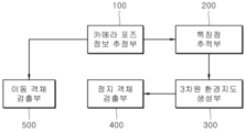
도 1을 참조하면 본 발명의 일 실시예에 따른 차량의 객체 검출 장치는 카메라 포즈 추정부(100), 특징점 추적부(200), 3차원 환경지도 생성부(300), 정지 객체 검출부(400) 및 이동 객체 검출부(500)를 포함할 수 있다. 카메라 포즈 추정부(100), 특징점 추적부(200), 3차원 환경지도 생성부(300) 및 정지 객체 검출부(400)를 통해 차량 주변의 정지 객체가 검출될 수 있고, 카메라 포즈 추정부(100) 및 이동 객체 검출부(500)를 통해 차량 주변의 이동 객체가 검출될 수 있다. 이하에서는 먼저 차량 주변의 정지 객체를 검출하는 과정에 대하여 설명한다.Referring to FIG. 1, an object detection device of a vehicle according to an embodiment of the present invention may include a camera pose estimation unit (100), a feature point tracking unit (200), a three-dimensional environment map generation unit (300), a stationary object detection unit (400), and a moving object detection unit (500). A stationary object around the vehicle may be detected through the camera pose estimation unit (100), the feature point tracking unit (200), the three-dimensional environment map generation unit (300), and the stationary object detection unit (400), and a moving object around the vehicle may be detected through the camera pose estimation unit (100) and the moving object detection unit (500). Hereinafter, a process of detecting a stationary object around the vehicle will first be described.
카메라 포즈 추정부(100)는 차량에 장착된 휠 속도 측정계를 통해 획득된 차량 포즈(Pose) 정보를 차량에 장착된 카메라의 좌표계로 변환하여 카메라 포즈 정보를 추정할 수 있다. 여기서, 차량 포즈 정보는 휠 속도 측정계를 통해 획득되는 차량의 자세 및 위치에 대한 정보를 포함할 수 있으며, 이에 따라 카메라 포즈 정보는 차량에 장착된 카메라의 자세 및 위치에 대한 정보를 포함할 수 있다.The camera pose estimation unit (100) can estimate camera pose information by converting vehicle pose information acquired through a wheel speed measuring device mounted on the vehicle into a coordinate system of a camera mounted on the vehicle. Here, the vehicle pose information can include information on the posture and position of the vehicle acquired through the wheel speed measuring device, and accordingly, the camera pose information can include information on the posture and position of the camera mounted on the vehicle.
이때, 카메라 포즈 추정부(100)는 차량의 후륜 축을 기준으로 결정되는 차량 포즈 정보에 카메라의 외부 파라미터를 적용하여 카메라 포즈 정보를 추정할 수 있다.At this time, the camera pose estimation unit (100) can estimate camera pose information by applying the external parameters of the camera to the vehicle pose information determined based on the rear wheel axis of the vehicle.
구체적으로, 본 실시예의 카메라 포즈 추정부(100)는 CAN 정보를 이용하여 짧은 구간에서 차량의 자세 및 위치를 제공하는 Wheel Odometry에 스케일(scale) 값을 융합한 Monocular Visual Odometry를 이용하여 카메라 포즈 정보를 추정할 수 있다. 즉, Wheel Odometry를 통해 획득되는 차량 포즈 정보는 후륜 축을 기준으로 하는 정보이므로, 카메라 포즈 추정부(100)는 도 2에 도시된 것과 같이 후륜 축 기준의 차량 포즈 정보에 카메라의 외부 파라미터(즉, 변환 매트릭스)를 적용하여 카메라 포즈 정보를 추정할 수 있다. 도 3에서 ①은 후륜 축 기준의 차량 포즈 정보를, ② 및 ③은 후륜 축 기준의 차량 포즈 정보로부터 변환된 카메라 포즈 정보를 나타낸다. 이에 따라, 카메라 포즈 정보는 하기 수학식 1에 의해 추정될 수 있다.Specifically, the camera pose estimation unit (100) of the present embodiment can estimate camera pose information by using Monocular Visual Odometry that fuses a scale value with Wheel Odometry, which provides the attitude and position of the vehicle in a short section by using CAN information. That is, since the vehicle pose information acquired through Wheel Odometry is information based on the rear wheel axle, the camera pose estimation unit (100) can estimate the camera pose information by applying the external parameter (i.e., transformation matrix) of the camera to the vehicle pose information based on the rear wheel axle, as illustrated in FIG. 2. In FIG. 3, ① represents vehicle pose information based on the rear wheel axle, and ② and ③ represent camera pose information converted from the vehicle pose information based on the rear wheel axle. Accordingly, the camera pose information can be estimated by the following mathematical expression 1.
![]()
![]()
한편, 카메라 포즈 추정부(100)는 카메라를 통해 획득된 이미지에 존재하는 특징점을 KLT(Kanade-Lucas-Tomasi) Tracking 알고리즘에 따라 추적하고, 추적된 특징점을 기반으로 카메라 포즈 정보를 최적화할 수도 있다. 즉, 카메라 포즈 추정부(100)는 카메라를 통해 획득된 이미지에 KLT Tracking 알고리즘을 적용하여 특징점을 추적하고, 추적된 특징점들을 이전 획득된 이미지(프레임)에 투영하여 결정되는 재투영 오차(Reprojection Error)가 최소화되도록 카메라 포즈 정보를 최적화할 수 있다. 카메라 포즈 정보의 최적화 과정에서 KLT Tracking 알고리즘에 따라 추적되는 특징점은 차량 주변의 정지 객체가 아닌, 이동 객체를 검출하는 과정에 활용될 수 있으며, 이에 대한 구체적인 설명은 후술한다. 또한, 카메라 포즈 추정부(100)는 카메라 포즈 정보를 최적화할 때, 일정 크기의 슬라이딩 윈도우(Sliding Window) 내의 이미지(프레임)만을 활용하여 카메라 포즈 정보의 최적화에 소요되는 시간이 단축되도록 할 수도 있다.Meanwhile, the camera pose estimation unit (100) may track feature points existing in an image acquired through the camera according to the KLT (Kanade-Lucas-Tomasi) Tracking algorithm, and may optimize the camera pose information based on the tracked feature points. That is, the camera pose estimation unit (100) may optimize the camera pose information so that the reprojection error determined by applying the KLT Tracking algorithm to the image acquired through the camera is minimized by projecting the tracked feature points onto the previously acquired image (frame). In the process of optimizing the camera pose information, the feature points tracked according to the KLT Tracking algorithm may be utilized in the process of detecting a moving object, not a stationary object around the vehicle, and a detailed description of this will be described later. In addition, when optimizing the camera pose information, the camera pose estimation unit (100) may utilize only images (frames) within a sliding window of a certain size so as to shorten the time required for optimizing the camera pose information.
특징점 추적부(200)는 카메라를 통해 획득된 이미지에 존재하는 포인트를 추출하여 이미지에 존재하는 기준 라인에 투영하고, 미리 정의된 특징점 추적 알고리즘에 따라 기준 라인에 투영된 포인트를 특징점으로서 추적할 수 있다.The feature point tracking unit (200) extracts points existing in an image acquired through a camera, projects them onto a reference line existing in the image, and can track points projected onto the reference line as feature points according to a predefined feature point tracking algorithm.
이때, 특징점 추적부(200)는 이미지에 존재하는 에지(Edge) 상의 포인트를 추출하여 기준 라인인 에피폴라 라인(Epipolar Line)에 투영하고, 에피폴라 제약조건(Epipolar Constraint)이 충족되는 범위에서 에피폴라 라인에 투영된 포인트를 특징점 추적 알고리즘인 KLT(Kanade-Lucas-Tomasi) Tracking 알고리즘에 따라 추적할 수 있다.At this time, the feature point tracking unit (200) extracts points on an edge existing in the image and projects them onto an epipolar line, which is a reference line, and can track the points projected onto the epipolar line according to the KLT (Kanade-Lucas-Tomasi) tracking algorithm, which is a feature point tracking algorithm, within a range where an epipolar constraint is satisfied.
통상적인 KLT Tracking 알고리즘은 이미지에 존재하는 코너(corner)에 해당하는 점을 추적하는 알고리즘으로서, 이미지에 존재하는 에지 상의 점에 대하여는 부정확한 결과를 제공하는 한계가 존재한다. 공간에서 고정된 점은 연속된 이미지에서 에피폴라 라인을 따라 이동하기 때문에, 본 실시예에서는 통상적인 KLT Tracking 알고리즘에 따라 특징점을 추정함이 아닌, Epipolar KLT Tracking 알고리즘을 활용하여 이미지에 존재하는 에지 상의 포인트도 강건하게 추적함으로써 정지 객체를 정밀하게 검출하는 구성을 채용한다. 도 4는 추적된 현재 프레임의 특징점, 및 추적된 이전 프레임의 특징점을 통상적인 KLT Tracking 알고리즘과 Epipolar KLT Tracking 알고리즘으로 구분하여 도시하고 있다.The conventional KLT Tracking algorithm is an algorithm that tracks points corresponding to corners in an image, and has a limitation in providing inaccurate results for points on edges in the image. Since a fixed point in space moves along an epipolar line in successive images, in this embodiment, instead of estimating feature points according to the conventional KLT Tracking algorithm, a configuration is adopted to robustly track points on edges in an image by utilizing the Epipolar KLT Tracking algorithm to precisely detect a stationary object. Fig. 4 illustrates feature points of a tracked current frame and feature points of a tracked previous frame, distinguished by the conventional KLT Tracking algorithm and the Epipolar KLT Tracking algorithm.
이에 따라, 특징점 추적부(200)는 이미지에 존재하는 에지 상의 포인트를 추출하여 에피폴라 라인에 투영하고, 에피폴라 제약조건(공간상의 한 점을 한 이미지에서 다른 이미지로 투영하였을 때 투영된 점은 에피폴라 라인상에 존재해야 하는 제약조건)이 충족되는 범위에서 에피폴라 라인에 투영된 포인트를 KLT Tracking 알고리즘에 따라 추적할 수 있다(즉, 이미지의 에지 포인트를 Epipolar KLT Tracking 알고리즘에 따라 특징점으로 추적할 수 있다).Accordingly, the feature point tracking unit (200) extracts points on an edge existing in an image, projects them onto an epipolar line, and tracks the points projected onto the epipolar line according to the KLT Tracking algorithm within a range where an epipolar constraint (a constraint that states that when a point in space is projected from one image to another, the projected point must exist on the epipolar line) is satisfied (i.e., the edge points of the image can be tracked as feature points according to the Epipolar KLT Tracking algorithm).
3차원 환경지도 생성부(300)는 카메라 포즈 추정부(100)에 의해 추정된 카메라 포즈 정보를 이용하여 특징점 추적부(200)에 의해 추적된 복수의 특징점의 3차원 좌표를 계산하고, 계산된 3차원 좌표를 갖는 복수의 3차원 특징점에 기초하여 3차원 환경지도를 생성할 수 있다. 3차원 환경지도 생성부(300)는 카메라 포즈 정보를 토대로 삼각측량법(Triangulation)을 사용하여 복수의 특징점에 대한 3차원 좌표를 계산할 수 있다.The 3D environment map generation unit (300) calculates 3D coordinates of a plurality of feature points tracked by the feature point tracking unit (200) using the camera pose information estimated by the camera pose estimation unit (100), and can generate a 3D environment map based on the plurality of 3D feature points having the calculated 3D coordinates. The 3D environment map generation unit (300) can calculate 3D coordinates for a plurality of feature points using triangulation based on the camera pose information.
이때, 3차원 환경지도 생성부(300)는 복수의 3차원 특징점을 오차에 따른 신뢰도(Confidence)를 통해 필터링한 후, 필터링된 3차원 특징점들을 이용하여 3차원 환경지도를 생성할 수 있으며, 신뢰도는 전술한 에지 포인트가 투영된 에피폴라 라인 및 에지 간의 각도와, 특징점 추적부(200)에 의해 추적된 이미지의 수에 기초하여 결정될 수 있다.At this time, the 3D environment map generation unit (300) can filter a plurality of 3D feature points through a confidence according to an error, and then generate a 3D environment map using the filtered 3D feature points. The confidence can be determined based on the angle between the epipolar line and the edge on which the aforementioned edge point is projected, and the number of images tracked by the feature point tracking unit (200).
구체적으로, Epipolar KLT Tracking 알고리즘은 에피폴라 라인과 에지 간의 방향이 비슷하고 추적된 이미지의 수가 적을수록 그 오차가 증가하는 경향이 있기 때문에, 3차원 환경지도 생성부(300)는 3차원 특징점에 대한 신뢰도를 계산하고, 계산된 신뢰도가 미리 설정된 기준치 이상일 경우에만 해당 3차원 특징점을 3차원 환경지도 생성에 반영함으로써, 기준치 이상의 신뢰도를 갖는 3차원 특징점을 기반으로 정지 객체가 검출되도록 하여 그 검출 정밀도를 향상시킬 수 있다. 3차원 환경지도 생성부(300)는 하기 수학식 2에 따라 3차원 특징점의 신뢰도를 결정할 수 있다.Specifically, since the Epipolar KLT Tracking algorithm tends to have an error that increases as the direction between the epipolar line and the edge is similar and the number of tracked images is small, the 3D environment map generation unit (300) calculates the reliability of the 3D feature point and reflects the 3D feature point in the 3D environment map generation only when the calculated reliability is higher than a preset reference value, thereby improving the detection accuracy by allowing stationary objects to be detected based on the 3D feature point having a reliability higher than the reference value. The 3D environment map generation unit (300) can determine the reliability of the 3D feature point according to the following mathematical expression 2.
수학식 2에서, C는 해당 3차원 특징점의 신뢰도, α는 에피폴라 라인 및 에지 간의 각도와 추적된 이미지의 수에 대한 가중치 비율, COSTangle은 에피폴라 라인 및 에지 간의 각도에 대한 코스트, COSTage는 추적된 이미지의 수에 대한 코스트를 의미한다.In mathematical expression 2, C represents the reliability of the corresponding 3D feature point, α represents the weight ratio for the angle between the epipolar line and the edge and the number of tracked images, COST angle represents the cost for the angle between the epipolar line and the edge, and COST age represents the cost for the number of tracked images.
정지 객체 검출부(400)는 3차원 환경지도 생성부(300)에 의해 생성된 3차원 환경지도 상의 3차원 특징점들을 기준 평면에 투영하는 방식을 통해 군집화하고, 군집화한 결과를 토대로 차량의 주변의 정지 객체를 검출할 수 있다. 여기서, 3차원 특징점들이 투영되는 기준 평면은 격자(Grid)가 형성된 지면(Ground Plane)으로 결정될 수 있으며, 지면은 카메라의 외부 파라미터를 기반으로 정의될 수 있다.The stationary object detection unit (400) can detect stationary objects around the vehicle based on the clustering result by projecting 3D feature points on the 3D environment map generated by the 3D environment map generation unit (300) onto a reference plane, thereby clustering. Here, the reference plane on which the 3D feature points are projected can be determined as a ground plane on which a grid is formed, and the ground plane can be defined based on external parameters of the camera.
이때, 정지 객체 검출부(400)는 3차원 환경지도 상의 3차원 특징점들 중 기준 평면(지면) 위에 존재하는 3차원 특징점만을 기준 평면에 투영하고, 투영된 3차원 특징점의 수를 각 격자별로 계산한 후, 그 계산 결과를 토대로 각 격자를 분류하는 방식을 통해 차량의 주변의 정지 객체를 검출할 수 있다.At this time, the stationary object detection unit (400) can detect stationary objects around the vehicle by projecting only the 3D feature points existing on the reference plane (ground) among the 3D feature points on the 3D environment map onto the reference plane, calculating the number of projected 3D feature points for each grid, and then classifying each grid based on the calculation result.
구체적으로, 정지 객체 검출부(400)는 도 5에 도시된 것과 같이 3차원 환경지도 상의 3차원 특징점들 중 지면 아래에 존재하는 3차원 특징점을 제거하고 지면 위에 존재하는 3차원 특징점만을 추출할 수 있다. 그리고, 정지 객체 검출부(400)는 도 6에 도시된 것과 같이 추출된 3차원 특징점을 지면에 투영하고(도 6의 좌측 도면), 투영된 3차원 특징점의 수를 각 격자별로 계산할 수 있다(도 6의 가운데 도면). Specifically, the stationary object detection unit (400) can remove 3D feature points existing below the ground among 3D feature points on a 3D environment map as illustrated in FIG. 5 and extract only 3D feature points existing above the ground. In addition, the stationary object detection unit (400) can project the extracted 3D feature points onto the ground as illustrated in FIG. 6 (left drawing of FIG. 6) and calculate the number of projected 3D feature points for each grid (middle drawing of FIG. 6).
이후, 정지 객체 검출부(400)는 각 격자별로 계산된 3차원 특징점의 수를 토대로 Connected Component 알고리즘을 이용하여 각 격자를 분류하고, 동일한 Component를 갖는 격자는 동일한 객체에 해당하는 것으로 판단하여 정지 객체를 검출할 수 있으며, 이때 해당 격자의 위치 및 해당 격자에 투영된 3차원 특징점의 수를 기반으로 해당 정지 객체의 위치 및 높이를 각각 계산하여 해당 정지 객체를 검출할 수 있다.Thereafter, the stationary object detection unit (400) classifies each grid using the Connected Component algorithm based on the number of 3D feature points calculated for each grid, and determines that grids having the same component correspond to the same object, thereby detecting a stationary object. At this time, the stationary object can be detected by calculating the position and height of the stationary object based on the position of the grid and the number of 3D feature points projected onto the grid.
즉, Connected Component 알고리즘에 따라 각 격자에는 라벨 번호가 부여되며, 이에 따라 정지 객체 검출부(400)는 동일한 Component를 갖는 격자(즉, 라벨 번호가 동일한 격자)에는 동일한 객체가 존재하는 것으로 판단하여 정지 객체를 검출할 수 있다(도 6의 우측 도면). 이때, 정지 객체 검출부(400)는 해당 격자의 위치를 토대로 해당 정지 객체의 위치를 계산하고, 해당 격자에 투영된 3차원 특징점의 수를 토대로 해당 정지 객체를 계산함으로써 해당 정지 객체를 검출할 수 있다. 도 7의 좌측 도면은 정지 객체 검출부(400)에 의해 최종 검출된 정지 객체를 도시하고 있으며(좌우측 박스에 해당하는 객체는 차량의 궤적 밖에 존재하는 정지 객체를, 가운데 박스에 해당하는 객체는 차량의 궤적 내에 존재하는 정지 객체를 나타낸다), 도 7의 우측 도면은 각각 각 격자별로 투영된 특징점의 수, 및 동일한 객체에 해당하는 격자끼리 분류된 라벨 번호에 대한 각 그래프를 도시하고 있다.That is, according to the Connected Component algorithm, each grid is assigned a label number, and accordingly, the stationary object detection unit (400) can detect stationary objects by judging that the same object exists in grids having the same component (i.e., grids with the same label number) (right drawing of FIG. 6). At this time, the stationary object detection unit (400) calculates the position of the stationary object based on the position of the corresponding grid, and calculates the stationary object based on the number of 3D feature points projected onto the corresponding grid, thereby detecting the stationary object. The left drawing of FIG. 7 illustrates the stationary object finally detected by the stationary object detection unit (400) (the object corresponding to the left and right boxes represents a stationary object existing outside the vehicle's trajectory, and the object corresponding to the middle box represents a stationary object existing within the vehicle's trajectory), and the right drawing of FIG. 7 illustrates each graph for the number of feature points projected for each grid, and the label number classified between grids corresponding to the same object.
다음으로, 차량 주변의 이동 객체를 검출하는 과정에 대하여 설명한다.Next, we describe the process of detecting moving objects around the vehicle.
이동 객체 검출부(500)는 카메라 포즈 추정부(100)에 의한 카메라 포즈 정보의 최적화 과정에서 KLT Tracking 알고리즘에 따라 추적된 특징점을 기반으로 차량의 주변의 이동 객체를 검출할 수 있다. 즉, 이동 객체는 에피폴라 제약조건을 따르지 않아 전술한 Epipolar KLT Tracking 알고리즘을 적용할 수 없으므로, 이동 객체를 검출하는 경우에는 카메라 포즈 추정부(100)가 카메라 포즈 정보를 추정하는 과정에서 활용되며 에피폴라 제약조건을 따르지 않는 일반적인 KLT Tracking 알고리즘을 활용한다. 도 8은 이동 객체 검출부(500)의 동작 원리를 도시하고 있으며, 즉 정지 객체의 경우 카메라의 이동 거리만큼 역 방향으로의 이동이 예상되며, 따라서 기준 평면(Global Ground Plane) 상에서 해당 객체의 예상 위치 및 실제 위치를 비교하고 그 차이가 클수록 이동 객체에 확률이 높음을 보이고 있다.The moving object detection unit (500) can detect moving objects around the vehicle based on feature points tracked according to the KLT Tracking algorithm in the process of optimizing camera pose information by the camera pose estimation unit (100). That is, since moving objects do not follow the epipolar constraint, the aforementioned Epipolar KLT Tracking algorithm cannot be applied. Therefore, when detecting moving objects, the camera pose estimation unit (100) is utilized in the process of estimating camera pose information, and a general KLT Tracking algorithm that does not follow the epipolar constraint is utilized. Fig. 8 illustrates the operating principle of the moving object detection unit (500). That is, in the case of a stationary object, movement in the reverse direction is expected by the movement distance of the camera, and therefore, the expected position and actual position of the object on the reference plane (Global Ground Plane) are compared, and the larger the difference, the higher the probability that it is a moving object.
전술한 내용을 토대로 이동 객체 검출부(500)의 동작을 구체적으로 설명하면, 이동 객체 검출부(500)는 카메라 포즈 추정 과정에서 활용되는 KLT Tracking 알고리즘에 따라 추적된 특징점에 대한, 이미지 상에서의 픽셀의 위치 좌표 및 3차원 좌표 간의 차이를 누적 분석하고 이동 객체로 추정되는 특징점을 검출하여 이동 스코어를 증가시키고, 이미지에 형성된 격자 별로 카운트되는 이동 스코어가 미리 설정된 기준치를 초과하면 해당 격자는 이동 객체에 해당하는 것으로 판단하여 이동 객체를 검출할 수 있다.Based on the above-described contents, the operation of the moving object detection unit (500) will be specifically explained. The moving object detection unit (500) accumulates and analyzes the difference between the position coordinates of pixels on the image and the 3D coordinates for the feature points tracked according to the KLT Tracking algorithm utilized in the camera pose estimation process, detects feature points estimated to be moving objects, increases the movement score, and if the movement score counted for each grid formed in the image exceeds a preset reference value, the grid is determined to correspond to a moving object, thereby detecting the moving object.
즉, 이동 객체 검출부(500)는 도 9에 도시된 것과 같이 KLT Tracking 알고리즘에 따라 추적된 특징점에 대한 2D 이미지 상에서의 픽셀의 위치 좌표 및 글로벌 3차원 좌표 간의 차이를 누적 분석하고 이동 객체에 해당하는 것으로 추정되는 특징점을 검출하여 이동 스코어를 증가시키고, 이미지에 형성된 격자 별로 이동 스코어를 카운트하여 그 값이 미리 설정된 기준치를 초과하면 해당 격자를 Dynamic Box로 분류하여 해당 Dynamic Box에 이동 객체가 존재하는 것으로 판단하는 방식을 통해 이동 객체를 검출할 수 있다.That is, the moving object detection unit (500) can detect a moving object by accumulating and analyzing the difference between the position coordinates of pixels on a 2D image and the global 3D coordinates for feature points tracked according to the KLT Tracking algorithm as illustrated in FIG. 9, detecting feature points estimated to correspond to moving objects and increasing the movement score, counting the movement score for each grid formed in the image, and classifying the corresponding grid as a Dynamic Box if the value exceeds a preset reference value, thereby determining that a moving object exists in the corresponding Dynamic Box.
도 10은 본 발명의 일 실시예에 따른 차량의 객체 검출 방법을 설명하기 위한 흐름도로서, 도 10을 참조하여 본 발명의 일 실시예에 따른 차량의 객체 검출 방법을 설명하며, 이하에서는 전술한 내용과 중복되는 설명은 생략한다.FIG. 10 is a flowchart for explaining a method for detecting an object in a vehicle according to one embodiment of the present invention. Referring to FIG. 10, a method for detecting an object in a vehicle according to one embodiment of the present invention will be explained, and any explanation that overlaps with the above-described content will be omitted below.
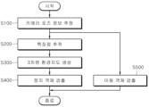
먼저, 카메라 포즈 추정부(100)는 차량의 휠 속도 측정계를 통해 획득된 차량 포즈(Pose) 정보를 차량의 카메라의 좌표계로 변환하여 카메라 포즈 정보를 추정한다(S100). S100 단계에서, 카메라 포즈 추정부(100)는 차량의 후륜 축을 기준으로 결정되는 차량 포즈 정보에 카메라의 외부 파라미터를 적용하여 카메라 포즈 정보를 추정한다. 또한, S100 단계에서, 카메라 포즈 추정부(100)는 카메라를 통해 획득된 이미지에 존재하는 특징점을 KLT Tracking 알고리즘에 따라 추적하고, 추적된 특징점을 기반으로 카메라 포즈 정보를 최적화한다.First, the camera pose estimation unit (100) converts vehicle pose information acquired through the wheel speed measurement unit of the vehicle into the coordinate system of the vehicle's camera to estimate the camera pose information (S100). In step S100, the camera pose estimation unit (100) estimates the camera pose information by applying the external parameters of the camera to the vehicle pose information determined based on the rear wheel axle of the vehicle. In addition, in step S100, the camera pose estimation unit (100) tracks feature points existing in an image acquired through the camera according to the KLT Tracking algorithm, and optimizes the camera pose information based on the tracked feature points.
이어서, 특징점 추적부(200)는 카메라를 통해 획득된 이미지에 존재하는 포인트를 추출하여 이미지에 존재하는 기준 라인에 투영하고, 미리 정의된 특징점 추적 알고리즘에 따라 기준 라인에 투영된 포인트를 특징점으로서 추적한다(S200). S200 단계에서, 특징점 추적부(200)는 이미지에 존재하는 에지(Edge) 상의 포인트를 추출하여 기준 라인인 에피폴라 라인(Epipolar Line)에 투영하고, 에피폴라 제약조건(Epipolar Constraint)이 충족되는 범위에서 에피폴라 라인에 투영된 포인트를 특징점 추적 알고리즘인 KLT(Kanade-Lucas-Tomasi) Tracking 알고리즘에 따라 추적한다.Next, the feature point tracking unit (200) extracts points existing in an image acquired through a camera, projects them onto a reference line existing in the image, and tracks the points projected onto the reference line as feature points according to a predefined feature point tracking algorithm (S200). In step S200, the feature point tracking unit (200) extracts points on an edge existing in the image, projects them onto an epipolar line, which is a reference line, and tracks the points projected onto the epipolar line according to the KLT (Kanade-Lucas-Tomasi) Tracking algorithm, which is a feature point tracking algorithm, within a range in which an epipolar constraint is satisfied.
이어서, 3차원 환경지도 생성부(300)는 S100 단계에서 추정된 카메라 포즈 정보를 이용하여 S200 단계에서 추적된 복수의 특징점의 3차원 좌표를 계산하고, 계산된 3차원 좌표를 갖는 복수의 3차원 특징점에 기초하여 3차원 환경지도를 생성한다(S300). S300 단계에서, 3차원 환경지도 생성부(300)는 복수의 3차원 특징점을 오차에 따른 신뢰도를 통해 필터링한 후, 필터링된 3차원 특징점들을 이용하여 3차원 환경지도를 생성하며, 3차원 특징점의 신뢰도는 에피폴라 라인 및 에지 간의 각도와, 특징점 추적부(200)에 의해 추적된 이미지의 수에 기초하여 결정될 수 있다.Next, the 3D environment map generation unit (300) calculates 3D coordinates of a plurality of feature points tracked in step S200 using the camera pose information estimated in step S100, and generates a 3D environment map based on the plurality of 3D feature points having the calculated 3D coordinates (S300). In step S300, the 3D environment map generation unit (300) filters the plurality of 3D feature points through reliability according to an error, and then generates a 3D environment map using the filtered 3D feature points. The reliability of the 3D feature points can be determined based on the angle between the epipolar line and the edge, and the number of images tracked by the feature point tracking unit (200).
이어서, 정지 객체 검출부(400)는 3차원 환경지도 생성부(300)에 의해 생성된 3차원 환경지도 상의 3차원 특징점들을 기준 평면에 투영하는 방식을 통해 군집화하고, 군집화한 결과를 토대로 차량의 주변의 정지 객체를 검출한다(S400). S400 단계에서, 정지 객체 검출부(400)는 3차원 환경지도 상의 3차원 특징점들 중 기준 평면 위에 존재하는 3차원 특징점만을 기준 평면에 투영하고, 투영된 3차원 특징점의 수를 각 격자별로 계산한 후, 각 격자별로 계산된 3차원 특징점의 수를 토대로 Connected Component 알고리즘을 이용하여 각 격자를 분류하고, 동일한 Component를 갖는 격자는 동일한 객체에 해당하는 것으로 판단하여 정지 객체를 검출한다. 이때, 정지 객체 검출부(400)는 해당 격자에 투영된 특징점들의 위치 및 개수를 기반으로 해당 정지 객체의 위치 및 높이를 계산하여 해당 정지 객체를 검출한다.Next, the stationary object detection unit (400) clusters the 3D feature points on the 3D environmental map generated by the 3D environmental map generation unit (300) by projecting them onto a reference plane, and detects stationary objects around the vehicle based on the clustering results (S400). In step S400, the stationary object detection unit (400) projects only the 3D feature points existing on the reference plane among the 3D feature points on the 3D environmental map onto the reference plane, calculates the number of projected 3D feature points for each grid, and then classifies each grid using a Connected Component algorithm based on the number of 3D feature points calculated for each grid, and detects stationary objects by determining that grids having the same component correspond to the same object. At this time, the stationary object detection unit (400) calculates the position and height of the stationary object based on the position and number of feature points projected onto the corresponding grid, and detects the stationary object.
한편, 이동 객체 검출부(500)는 S100 단계의 카메라 포즈 정보의 최적화 과정에서 KLT Tracking 알고리즘에 따라 추적된 특징점을 기반으로 차량의 주변의 이동 객체를 검출한다(S500). S500 단계에서 이동 객체 검출부(500)는 KLT Tracking 알고리즘에 따라 추적된 특징점에 대한, 이미지 상에서의 픽셀의 위치 좌표 및 3차원 좌표 간의 차이를 누적 분석하고 이동 객체로 추정되는 특징점을 검출하여 이동 스코어를 증가시키고, 이미지에 형성된 격자 별로 카운트되는 이동 스코어가 미리 설정된 기준치를 초과하면 해당 격자는 이동 객체에 해당하는 것으로 판단하여 이동 객체를 검출한다. S500 단계는 S100 단계 내지 S400 단계와 독립적으로 수행되는 병렬적 구성으로서, 그 동작 순서가 상기한 기재순서에 한정되지 않는다.Meanwhile, the moving object detection unit (500) detects a moving object around the vehicle based on the feature points tracked according to the KLT Tracking algorithm in the process of optimizing the camera pose information in step S100 (S500). In step S500, the moving object detection unit (500) accumulates and analyzes the difference between the position coordinates of pixels on the image and the 3D coordinates for the feature points tracked according to the KLT Tracking algorithm, detects feature points estimated to be moving objects, increases the movement score, and if the movement score counted for each grid formed in the image exceeds a preset reference value, the grid is determined to correspond to a moving object and detects the moving object. Step S500 is a parallel configuration performed independently from steps S100 to S400, and its operation order is not limited to the above-described description order.
이와 같이 본 실시예는 차량의 카메라를 통해 획득되는 이미지 영상과 차량의 휠 속도 측정계를 활용하여 차량 주변의 3차원 환경지도를 구축하고, 구축된 3차원 환경지도를 기반으로 차량 궤적 상의 객체를 검출하는 방식을 통해 차량 주변의 정지 객체 및 이동 객체를 정밀하게 검출함으로써 운전자의 주행 편의를 향상시킬 수 있다.In this way, the present embodiment constructs a three-dimensional environment map around the vehicle by utilizing image footage acquired through the vehicle's camera and the vehicle's wheel speed meter, and detects objects on the vehicle's trajectory based on the constructed three-dimensional environment map, thereby enabling precise detection of stationary and moving objects around the vehicle, thereby improving the driver's driving convenience.
또한, 본 실시예는 차량의 자율 주행 시스템 또는 주차 보조 시스템에 적용되어 차량 주변의 장애물과 같은 객체를 검출하고 그 검출 결과를 기반으로 차량의 자율 주행 또는 주차가 정확하게 제어되도록 함으로써 차량의 자율 주행 제어 성능 및 주차 제어 성능이 개선되도록 할 수 있다.In addition, the present embodiment can be applied to an autonomous driving system or a parking assistance system of a vehicle to detect objects such as obstacles around the vehicle and accurately control autonomous driving or parking of the vehicle based on the detection results, thereby improving the autonomous driving control performance and parking control performance of the vehicle.
본 명세서에서 설명된 구현은, 예컨대, 방법 또는 프로세스, 장치, 소프트웨어 프로그램, 데이터 스트림 또는 신호로 구현될 수 있다. 단일 형태의 구현의 맥락에서만 논의(예컨대, 방법으로서만 논의)되었더라도, 논의된 특징의 구현은 또한 다른 형태(예컨대, 장치 또는 프로그램)로도 구현될 수 있다. 장치는 적절한 하드웨어, 소프트웨어 및 펌웨어 등으로 구현될 수 있다. 방법은, 예컨대, 컴퓨터, 마이크로프로세서, 집적 회로 또는 프로그래밍가능한 로직 디바이스 등을 포함하는 프로세싱 디바이스를 일반적으로 지칭하는 프로세서 등과 같은 장치에서 구현될 수 있다. 프로세서는 또한 최종-사용자 사이에 정보의 통신을 용이하게 하는 컴퓨터, 셀 폰, 휴대용/개인용 정보 단말기(personal digital assistant: "PDA") 및 다른 디바이스 등과 같은 통신 디바이스를 포함한다.The implementations described herein may be implemented, for example, as a method or process, an apparatus, a software program, a data stream or a signal. Even if discussed in the context of only a single form of implementation (e.g., discussed only as a method), the implementation of the discussed features may also be implemented in other forms (e.g., as an apparatus or a program). The apparatus may be implemented using suitable hardware, software, firmware, and the like. The method may be implemented in an apparatus such as a processor, which generally refers to a processing device including, for example, a computer, a microprocessor, an integrated circuit, or a programmable logic device. A processor also includes a communication device such as a computer, a cell phone, a personal digital assistant ("PDA"), and other devices that facilitate communication of information between end-users.
본 발명은 도면에 도시된 실시예를 참고로 하여 설명되었으나, 이는 예시적인 것에 불과하며 당해 기술이 속하는 기술분야에서 통상의 지식을 가진 자라면 이로부터 다양한 변형 및 균등한 타 실시예가 가능하다는 점을 이해할 것이다. 따라서, 본 발명의 진정한 기술적 보호범위는 아래의 특허청구범위에 의하여 정해져야 할 것이다.Although the present invention has been described with reference to the embodiments shown in the drawings, these are merely exemplary, and those skilled in the art will understand that various modifications and equivalent other embodiments are possible from this. Accordingly, the true technical protection scope of the present invention should be determined by the following patent claims.
100: 카메라 포즈 추정부
200: 특징점 추적부
300: 3차원 환경지도 생성부
400: 정지 객체 검출부
500: 이동 객체 검출부100: Camera Pose Estimation Unit
200: Feature point tracking unit
300: 3D environment map generation unit
400: Stationary object detection unit
500: Moving Object Detection Unit
Claims (18)
상기 카메라를 통해 획득된 이미지에 존재하는 포인트를 추출하여 상기 이미지에 존재하는 기준 라인에 투영하고, 미리 정의된 특징점 추적 알고리즘에 따라 상기 기준 라인에 투영된 포인트를 특징점으로서 추적하는 특징점 추적부;
상기 카메라 포즈 추정부에 의해 추정된 카메라 포즈 정보를 이용하여 상기 특징점 추적부에 의해 추적된 복수의 특징점의 3차원 좌표를 계산하고, 상기 계산된 3차원 좌표를 갖는 복수의 3차원 특징점에 기초하여 3차원 환경지도를 생성하는 3차원 환경지도 생성부; 및
상기 3차원 환경지도 생성부에 의해 생성된 3차원 환경지도 상의 3차원 특징점들을 기준 평면에 투영하는 방식을 통해 군집화하고, 군집화한 결과를 토대로 상기 차량의 주변의 정지 객체를 검출하는 정지 객체 검출부;
를 포함하는 것을 특징으로 하는 차량의 객체 검출 장치.
A camera pose estimation unit that estimates camera pose information by converting vehicle pose information obtained through a wheel speed measurement system of the vehicle into the coordinate system of the camera of the vehicle;
A feature point tracking unit that extracts points existing in an image acquired through the camera, projects them onto a reference line existing in the image, and tracks the points projected onto the reference line as feature points according to a predefined feature point tracking algorithm;
A 3D environment map generation unit that calculates 3D coordinates of a plurality of feature points tracked by the feature point tracking unit using the camera pose information estimated by the camera pose estimation unit, and generates a 3D environment map based on the plurality of 3D feature points having the calculated 3D coordinates; and
A stationary object detection unit that clusters 3D feature points on a 3D environmental map generated by the 3D environmental map generation unit by projecting them onto a reference plane, and detects stationary objects around the vehicle based on the clustering results;
An object detection device for a vehicle, characterized by including a .
상기 카메라 포즈 추정부는, 상기 차량의 후륜 축을 기준으로 결정되는 상기 차량 포즈 정보에 상기 카메라의 외부 파라미터를 적용하여 상기 카메라 포즈 정보를 추정하는 것을 특징으로 하는 차량의 객체 검출 장치.
In the first paragraph,
An object detection device for a vehicle, characterized in that the camera pose estimation unit estimates the camera pose information by applying the external parameters of the camera to the vehicle pose information determined based on the rear wheel axis of the vehicle.
상기 특징점 추적부는, 상기 이미지에 존재하는 에지(Edge) 상의 포인트를 추출하고 상기 기준 라인에 투영하여 특징점을 추적하는 것을 특징으로 차량의 객체 검출 장치.
In the first paragraph,
An object detection device for a vehicle, characterized in that the above-mentioned feature point tracking unit extracts points on an edge existing in the image and projects them onto the reference line to track feature points.
상기 특징점 추적부는, 상기 에지 상의 포인트를 상기 기준 라인인 에피폴라 라인(Epipolar Line)에 투영하고, 에피폴라 제약조건(Epipolar Constraint)이 충족되는 범위에서 상기 에피폴라 라인에 투영된 포인트를 상기 특징점 추적 알고리즘인 KLT(Kanade-Lucas-Tomasi) Tracking 알고리즘에 따라 추적하는 것을 특징으로 하는 차량의 객체 검출 장치.
In the third paragraph,
An object detection device for a vehicle, characterized in that the above-described feature point tracking unit projects a point on the edge onto an epipolar line, which is the reference line, and tracks the point projected onto the epipolar line according to the KLT (Kanade-Lucas-Tomasi) Tracking algorithm, which is the feature point tracking algorithm, within a range in which an epipolar constraint is satisfied.
상기 3차원 환경지도 생성부는, 상기 복수의 3차원 특징점을 오차에 따른 신뢰도를 통해 필터링한 후, 상기 필터링된 3차원 특징점들을 이용하여 상기 3차원 환경지도를 생성하는 것을 특징으로 하는 차량의 객체 검출 장치.
In paragraph 4,
A vehicle object detection device, characterized in that the above-mentioned 3D environment map generation unit filters the plurality of 3D feature points through reliability according to error, and then generates the 3D environment map using the filtered 3D feature points.
상기 신뢰도는 상기 에피폴라 라인 및 상기 에지 간의 각도와, 상기 특징점 추적부에 의해 추적된 이미지의 수에 기초하여 결정되는 것을 특징으로 하는 차량의 객체 검출 장치.
In paragraph 5,
An object detection device for a vehicle, characterized in that the reliability is determined based on the angle between the epipolar line and the edge and the number of images tracked by the feature point tracking unit.
상기 기준 평면은 격자(Grid)가 형성된 지면(Ground Plane)으로 결정되고,
상기 정지 객체 검출부는, 상기 3차원 환경지도 상의 3차원 특징점들 중 상기 기준 평면 위에 존재하는 3차원 특징점만을 상기 기준 평면에 투영하고, 투영된 3차원 특징점의 수를 각 격자별로 계산한 후, 그 계산 결과를 토대로 각 격자를 분류하는 방식을 통해 상기 차량의 주변의 정지 객체를 검출하는 것을 특징으로 하는 차량의 객체 검출 장치.
In the first paragraph,
The above reference plane is determined as the ground plane on which the grid is formed,
The above-mentioned stationary object detection unit detects stationary objects around the vehicle by projecting only 3D feature points existing on the reference plane among 3D feature points on the 3D environment map onto the reference plane, calculating the number of projected 3D feature points for each grid, and then classifying each grid based on the calculation result. The vehicle object detection device is characterized in that.
상기 정지 객체 검출부는, 상기 각 격자별로 계산된 3차원 특징점의 수를 토대로 Connected Component 알고리즘을 이용하여 각 격자를 분류하고, 동일한 Component를 갖는 격자는 동일한 객체에 해당하는 것으로 판단하여 정지 객체를 검출하되, 해당 격자의 위치 및 해당 격자에 투영된 3차원 특징점의 수를 기반으로 해당 정지 객체의 위치 및 높이를 계산하여 해당 정지 객체를 검출하는 것을 특징으로 하는 차량의 객체 검출 장치.
In Article 7,
The above stationary object detection unit classifies each grid using a Connected Component algorithm based on the number of three-dimensional feature points calculated for each grid, determines that grids having the same component correspond to the same object, and detects a stationary object, and calculates the position and height of the stationary object based on the position of the grid and the number of three-dimensional feature points projected onto the grid, thereby detecting the stationary object. An object detection device for a vehicle.
상기 카메라 포즈 추정부는, 상기 카메라를 통해 획득된 이미지에 존재하는 특징점을 KLT Tracking 알고리즘에 따라 추적하고, 상기 추적된 특징점을 기반으로 상기 카메라 포즈 정보를 최적화하고,
상기 카메라 포즈 정보의 최적화 과정에서 상기 KLT Tracking 알고리즘에 따라 추적된 특징점을 기반으로 상기 차량의 주변의 이동 객체를 검출하는 이동 객체 검출부;를 더 포함하는 것을 특징으로 하는 차량의 객체 검출 장치.
In the first paragraph,
The above camera pose estimation unit tracks feature points existing in an image acquired through the camera according to the KLT Tracking algorithm, and optimizes the camera pose information based on the tracked feature points.
An object detection device for a vehicle, characterized in that it further includes a moving object detection unit that detects a moving object around the vehicle based on feature points tracked according to the KLT Tracking algorithm during the optimization process of the camera pose information.
상기 이동 객체 검출부는, 상기 KLT Tracking 알고리즘에 따라 추적된 특징점에 대한, 상기 이미지 상에서의 픽셀의 위치 좌표 및 3차원 좌표 간의 차이를 누적 분석하고 이동 객체로 추정되는 특징점을 검출하여 이동 스코어를 증가시키고, 상기 이미지에 형성된 격자 별로 카운트되는 상기 이동 스코어가 미리 설정된 기준치를 초과하면 해당 격자는 이동 객체에 해당하는 것으로 판단하여 이동 객체를 검출하는 것을 특징으로 하는 차량의 객체 검출 장치.
In Article 9,
The above moving object detection unit accumulates and analyzes the difference between the position coordinates of pixels on the image and the three-dimensional coordinates for the feature points tracked according to the KLT Tracking algorithm, detects feature points estimated to be moving objects and increases a movement score, and if the movement score counted for each grid formed in the image exceeds a preset reference value, determines that the corresponding grid corresponds to a moving object and detects the moving object. The object detection device of a vehicle is characterized in that.
특징점 추적부가, 상기 카메라를 통해 획득된 이미지에 존재하는 포인트를 추출하여 상기 이미지에 존재하는 기준 라인에 투영하고, 미리 정의된 특징점 추적 알고리즘에 따라 상기 기준 라인에 투영된 포인트를 특징점으로서 추적하는 단계;
3차원 환경지도 생성부가, 상기 카메라 포즈 추정부에 의해 추정된 카메라 포즈 정보를 이용하여 상기 특징점 추적부에 의해 추적된 복수의 특징점의 3차원 좌표를 계산하고, 상기 계산된 3차원 좌표를 갖는 복수의 3차원 특징점에 기초하여 3차원 환경지도를 생성하는 단계; 및
정지 객체 검출부가, 상기 3차원 환경지도 생성부에 의해 생성된 3차원 환경지도 상의 3차원 특징점들을 기준 평면에 투영하는 방식을 통해 군집화하고, 군집화한 결과를 토대로 상기 차량의 주변의 정지 객체를 검출하는 단계;
를 포함하는 것을 특징으로 하는 차량의 객체 검출 방법.
A step for estimating camera pose information by converting vehicle pose information obtained through a wheel speed measuring device of the vehicle into a coordinate system of the camera of the vehicle;
A step of a feature point tracking unit extracting points existing in an image acquired through the camera, projecting them onto a reference line existing in the image, and tracking the points projected onto the reference line as feature points according to a predefined feature point tracking algorithm;
A step of a 3D environment map generation unit calculating 3D coordinates of a plurality of feature points tracked by the feature point tracking unit using the camera pose information estimated by the camera pose estimation unit, and generating a 3D environment map based on the plurality of 3D feature points having the calculated 3D coordinates; and
A step of detecting stationary objects around the vehicle by clustering 3D feature points on the 3D environmental map generated by the 3D environmental map generating unit by projecting them onto a reference plane, and based on the clustering results;
A method for detecting an object in a vehicle, characterized by including a .
상기 추정하는 단계에서, 상기 카메라 포즈 추정부는,
상기 차량의 후륜 축을 기준으로 결정되는 상기 차량 포즈 정보에 상기 카메라의 외부 파라미터를 적용하여 상기 카메라 포즈 정보를 추정하는 것을 특징으로 하는 차량의 객체 검출 방법.
In Article 11,
In the above estimating step, the camera pose estimation unit,
A method for detecting an object in a vehicle, characterized in that the camera pose information is estimated by applying an external parameter of the camera to the vehicle pose information determined based on the rear axle of the vehicle.
상기 추적하는 단계에서, 상기 특징점 추적부는,
상기 이미지에 존재하는 에지(Edge) 상의 포인트를 추출하여 상기 기준 라인인 에피폴라 라인(Epipolar Line)에 투영하고, 에피폴라 제약조건(Epipolar Constraint)이 충족되는 범위에서 상기 에피폴라 라인에 투영된 포인트를 상기 특징점 추적 알고리즘인 KLT(Kanade-Lucas-Tomasi) Tracking 알고리즘에 따라 추적하는 것을 특징으로 하는 차량의 객체 검출 방법.
In Article 11,
In the above tracking step, the feature point tracking unit,
A method for detecting an object in a vehicle, characterized in that points on an edge existing in the image are extracted, the points are projected onto an epipolar line, which is a reference line, and the points projected onto the epipolar line are tracked according to the KLT (Kanade-Lucas-Tomasi) Tracking algorithm, which is a feature point tracking algorithm, within a range in which an epipolar constraint is satisfied.
상기 생성하는 단계에서, 상기 3차원 환경지도 생성부는,
상기 복수의 3차원 특징점을 오차에 따른 신뢰도를 통해 필터링한 후, 상기 필터링된 3차원 특징점들을 이용하여 상기 3차원 환경지도를 생성하되, 상기 신뢰도는 상기 에피폴라 라인 및 상기 에지 간의 각도와, 상기 특징점 추적부에 의해 추적된 이미지의 수에 기초하여 결정되는 것을 특징으로 하는 차량의 객체 검출 방법.
In Article 13,
In the above generating step, the 3D environment map generating unit,
A method for detecting an object in a vehicle, characterized in that after filtering the plurality of three-dimensional feature points through a reliability according to an error, the three-dimensional environment map is generated using the filtered three-dimensional feature points, wherein the reliability is determined based on the angle between the epipolar line and the edge and the number of images tracked by the feature point tracking unit.
상기 기준 평면은 격자(Grid)가 형성된 지면(Ground Plane)으로 결정되고,
상기 검출하는 단계에서, 상기 정지 객체 검출부는,
상기 3차원 환경지도 상의 3차원 특징점들 중 상기 기준 평면 위에 존재하는 3차원 특징점만을 상기 기준 평면에 투영하고, 투영된 3차원 특징점의 수를 각 격자별로 계산한 후, 그 계산 결과를 토대로 각 격자를 분류하는 방식을 통해 상기 차량의 주변의 정지 객체를 검출하는 것을 특징으로 하는 차량의 객체 검출 방법.
In Article 11,
The above reference plane is determined as the ground plane on which the grid is formed,
In the above detecting step, the stationary object detection unit,
A vehicle object detection method characterized in that a stationary object around the vehicle is detected by projecting only the 3D feature points existing on the reference plane among the 3D feature points on the 3D environment map onto the reference plane, calculating the number of projected 3D feature points for each grid, and then classifying each grid based on the calculation result.
상기 검출하는 단계에서, 상기 정지 객체 검출부는,
상기 각 격자별로 계산된 3차원 특징점의 수를 토대로 Connected Component 알고리즘을 이용하여 각 격자를 분류하고, 동일한 Component를 갖는 격자는 동일한 객체에 해당하는 것으로 판단하여 정지 객체를 검출하되, 해당 격자의 위치 및 해당 격자에 투영된 3차원 특징점의 수를 기반으로 해당 정지 객체의 위치 및 높이를 계산하여 해당 정지 객체를 검출하는 것을 특징으로 하는 차량의 객체 검출 방법.
In Article 15,
In the above detecting step, the stationary object detection unit,
A vehicle object detection method characterized in that each grid is classified using a Connected Component algorithm based on the number of three-dimensional feature points calculated for each grid above, grids having the same component are judged to correspond to the same object, and a stationary object is detected, and the stationary object is detected by calculating the position and height of the stationary object based on the position of the grid and the number of three-dimensional feature points projected onto the grid.
상기 추정하는 단계에서, 상기 카메라 포즈 추정부는,
상기 카메라를 통해 획득된 이미지에 존재하는 특징점을 KLT Tracking 알고리즘에 따라 추적하고, 상기 추적된 특징점을 기반으로 상기 카메라 포즈 정보를 최적화하고,
이동 객체 검출부가, 상기 카메라 포즈 정보의 최적화 과정에서 상기 KLT Tracking 알고리즘에 따라 추적된 특징점을 기반으로 상기 차량의 주변의 이동 객체를 검출하는 단계;를 더 포함하는 것을 특징으로 하는 차량의 객체 검출 방법.
In Article 11,
In the above estimating step, the camera pose estimation unit,
Tracking feature points existing in the image acquired through the above camera according to the KLT Tracking algorithm, and optimizing the camera pose information based on the tracked feature points.
A method for detecting an object in a vehicle, characterized in that it further includes a step of detecting a moving object around the vehicle based on feature points tracked according to the KLT Tracking algorithm during the optimization process of the camera pose information.
상기 이동 객체를 검출하는 단계에서, 상기 이동 객체 검출부는,
상기 KLT Tracking 알고리즘에 따라 추적된 특징점에 대한, 상기 이미지 상에서의 픽셀의 위치 좌표 및 3차원 좌표 간의 차이를 누적 분석하고 이동 객체로 추정되는 특징점을 검출하여 이동 스코어를 증가시키고, 상기 이미지에 형성된 격자 별로 카운트되는 상기 이동 스코어가 미리 설정된 기준치를 초과하면 해당 격자는 이동 객체에 해당하는 것으로 판단하여 이동 객체를 검출하는 것을 특징으로 하는 차량의 객체 검출 방법.In Article 17,
In the step of detecting the above moving object, the moving object detection unit,
A method for detecting an object in a vehicle, characterized in that the method comprises: accumulating and analyzing differences between the position coordinates of pixels on the image and the three-dimensional coordinates for feature points tracked according to the KLT Tracking algorithm, detecting feature points estimated to be moving objects and increasing a movement score; and when the movement score counted for each grid formed in the image exceeds a preset reference value, determining that the corresponding grid corresponds to a moving object and detecting the moving object.
Priority Applications (1)
| Application Number | Priority Date | Filing Date | Title |
|---|---|---|---|
| KR1020190020287A KR102831462B1 (en) | 2019-02-21 | 2019-02-21 | Apparatus for detecting object of vehicle and method thereof |
Applications Claiming Priority (1)
| Application Number | Priority Date | Filing Date | Title |
|---|---|---|---|
| KR1020190020287A KR102831462B1 (en) | 2019-02-21 | 2019-02-21 | Apparatus for detecting object of vehicle and method thereof |
Publications (2)
| Publication Number | Publication Date |
|---|---|
| KR20200102108A KR20200102108A (en) | 2020-08-31 |
| KR102831462B1 true KR102831462B1 (en) | 2025-07-09 |
Family
ID=72234420
Family Applications (1)
| Application Number | Title | Priority Date | Filing Date |
|---|---|---|---|
| KR1020190020287A Active KR102831462B1 (en) | 2019-02-21 | 2019-02-21 | Apparatus for detecting object of vehicle and method thereof |
Country Status (1)
| Country | Link |
|---|---|
| KR (1) | KR102831462B1 (en) |
Families Citing this family (3)
| Publication number | Priority date | Publication date | Assignee | Title |
|---|---|---|---|---|
| KR102225093B1 (en) * | 2020-09-01 | 2021-03-09 | 주식회사 맥스트 | Apparatus and method for estimating camera pose |
| CN113763560B (en) * | 2021-08-02 | 2024-02-09 | 纵目科技(上海)股份有限公司 | Method, system, equipment and computer readable storage medium for generating point cloud data |
| KR102661942B1 (en) * | 2022-09-30 | 2024-04-29 | 에이치디현대로보틱스 주식회사 | Disinfection robot and controlling method thereof |
Citations (4)
| Publication number | Priority date | Publication date | Assignee | Title |
|---|---|---|---|---|
| US20140037136A1 (en) | 2012-08-01 | 2014-02-06 | Srikumar Ramalingam | Method and System for Determining Poses of Vehicle-Mounted Cameras for In-Road Obstacle Detection |
| US20180075320A1 (en) | 2016-09-12 | 2018-03-15 | Delphi Technologies, Inc. | Enhanced camera object detection for automated vehicles |
| WO2018125939A1 (en) | 2016-12-30 | 2018-07-05 | DeepMap Inc. | Visual odometry and pairwise alignment for high definition map creation |
| US20190033867A1 (en) | 2017-07-28 | 2019-01-31 | Qualcomm Incorporated | Systems and methods for determining a vehicle position |
-
2019
- 2019-02-21 KR KR1020190020287A patent/KR102831462B1/en active Active
Patent Citations (4)
| Publication number | Priority date | Publication date | Assignee | Title |
|---|---|---|---|---|
| US20140037136A1 (en) | 2012-08-01 | 2014-02-06 | Srikumar Ramalingam | Method and System for Determining Poses of Vehicle-Mounted Cameras for In-Road Obstacle Detection |
| US20180075320A1 (en) | 2016-09-12 | 2018-03-15 | Delphi Technologies, Inc. | Enhanced camera object detection for automated vehicles |
| WO2018125939A1 (en) | 2016-12-30 | 2018-07-05 | DeepMap Inc. | Visual odometry and pairwise alignment for high definition map creation |
| US20190033867A1 (en) | 2017-07-28 | 2019-01-31 | Qualcomm Incorporated | Systems and methods for determining a vehicle position |
Also Published As
| Publication number | Publication date |
|---|---|
| KR20200102108A (en) | 2020-08-31 |
Similar Documents
| Publication | Publication Date | Title |
|---|---|---|
| KR101776622B1 (en) | Apparatus for recognizing location mobile robot using edge based refinement and method thereof | |
| KR101725060B1 (en) | Apparatus for recognizing location mobile robot using key point based on gradient and method thereof | |
| KR101776621B1 (en) | Apparatus for recognizing location mobile robot using edge based refinement and method thereof | |
| US8564657B2 (en) | Object motion detection system based on combining 3D warping techniques and a proper object motion detection | |
| KR101784183B1 (en) | APPARATUS FOR RECOGNIZING LOCATION MOBILE ROBOT USING KEY POINT BASED ON ADoG AND METHOD THEREOF | |
| KR102054455B1 (en) | Apparatus and method for calibrating between heterogeneous sensors | |
| WO2022188094A1 (en) | Point cloud matching method and apparatus, navigation method and device, positioning method, and laser radar | |
| JP5023186B2 (en) | Object motion detection system based on combination of 3D warping technique and proper object motion (POM) detection | |
| US20160104047A1 (en) | Image recognition system for a vehicle and corresponding method | |
| US11151729B2 (en) | Mobile entity position estimation device and position estimation method | |
| KR20160123668A (en) | Device and method for recognition of obstacles and parking slots for unmanned autonomous parking | |
| JP2018124787A (en) | Information processing apparatus, data management apparatus, data management system, method, and program | |
| US10832428B2 (en) | Method and apparatus for estimating a range of a moving object | |
| JP7173471B2 (en) | 3D position estimation device and program | |
| US11080562B1 (en) | Key point recognition with uncertainty measurement | |
| CN118209101B (en) | Multi-sensor fusion SLAM method and system applied to dynamic environment | |
| US9098750B2 (en) | Gradient estimation apparatus, gradient estimation method, and gradient estimation program | |
| CN111829484A (en) | Vision-based target distance measurement method | |
| CN115187941A (en) | Target detection positioning method, system, equipment and storage medium | |
| CN113029185A (en) | Road marking change detection method and system in crowdsourcing type high-precision map updating | |
| KR20240050502A (en) | Method and System for Vehicle Pose Estimation using Optical Flow for Inter-Vehicle Distance Compensation in Dynamic Scenes | |
| KR102831462B1 (en) | Apparatus for detecting object of vehicle and method thereof | |
| CN121026152B (en) | Positioning and mapping method, system, equipment and medium based on dynamic vision | |
| US20250029401A1 (en) | Image processing device | |
| CN117606500A (en) | Deceleration strip detection method, deceleration strip passing method, network training method and related device |
Legal Events
| Date | Code | Title | Description |
|---|---|---|---|
| PA0109 | Patent application |
St.27 status event code: A-0-1-A10-A12-nap-PA0109 |
|
| R18-X000 | Changes to party contact information recorded |
St.27 status event code: A-3-3-R10-R18-oth-X000 |
|
| R18-X000 | Changes to party contact information recorded |
St.27 status event code: A-3-3-R10-R18-oth-X000 |
|
| P22-X000 | Classification modified |
St.27 status event code: A-2-2-P10-P22-nap-X000 |
|
| PG1501 | Laying open of application |
St.27 status event code: A-1-1-Q10-Q12-nap-PG1501 |
|
| P22-X000 | Classification modified |
St.27 status event code: A-2-2-P10-P22-nap-X000 |
|
| A201 | Request for examination | ||
| PA0201 | Request for examination |
St.27 status event code: A-1-2-D10-D11-exm-PA0201 |
|
| R18-X000 | Changes to party contact information recorded |
St.27 status event code: A-3-3-R10-R18-oth-X000 |
|
| D13-X000 | Search requested |
St.27 status event code: A-1-2-D10-D13-srh-X000 |
|
| E902 | Notification of reason for refusal | ||
| PE0902 | Notice of grounds for rejection |
St.27 status event code: A-1-2-D10-D21-exm-PE0902 |
|
| P11-X000 | Amendment of application requested |
St.27 status event code: A-2-2-P10-P11-nap-X000 |
|
| E701 | Decision to grant or registration of patent right | ||
| PE0701 | Decision of registration |
St.27 status event code: A-1-2-D10-D22-exm-PE0701 |
|
| PG1601 | Publication of registration |
St.27 status event code: A-4-4-Q10-Q13-nap-PG1601 |
|
| Q13 | Ip right document published |
Free format text: ST27 STATUS EVENT CODE: A-4-4-Q10-Q13-NAP-PG1601 (AS PROVIDED BY THE NATIONAL OFFICE) |