KR102752939B1 - Method and system for providing route of unmanned air vehicle - Google Patents
Method and system for providing route of unmanned air vehicle Download PDFInfo
- Publication number
- KR102752939B1 KR102752939B1 KR1020170011772A KR20170011772A KR102752939B1 KR 102752939 B1 KR102752939 B1 KR 102752939B1 KR 1020170011772 A KR1020170011772 A KR 1020170011772A KR 20170011772 A KR20170011772 A KR 20170011772A KR 102752939 B1 KR102752939 B1 KR 102752939B1
- Authority
- KR
- South Korea
- Prior art keywords
- unmanned aerial
- aerial vehicle
- flight
- layer
- route
- Prior art date
- Legal status (The legal status is an assumption and is not a legal conclusion. Google has not performed a legal analysis and makes no representation as to the accuracy of the status listed.)
- Active
Links
Images


Classifications
-
- G—PHYSICS
- G09—EDUCATION; CRYPTOGRAPHY; DISPLAY; ADVERTISING; SEALS
- G09B—EDUCATIONAL OR DEMONSTRATION APPLIANCES; APPLIANCES FOR TEACHING, OR COMMUNICATING WITH, THE BLIND, DEAF OR MUTE; MODELS; PLANETARIA; GLOBES; MAPS; DIAGRAMS
- G09B29/00—Maps; Plans; Charts; Diagrams, e.g. route diagram
- G09B29/003—Maps
- G09B29/004—Map manufacture or repair; Tear or ink or water resistant maps; Long-life maps
Landscapes
- Engineering & Computer Science (AREA)
- Physics & Mathematics (AREA)
- Theoretical Computer Science (AREA)
- Mathematical Physics (AREA)
- Business, Economics & Management (AREA)
- Educational Administration (AREA)
- Educational Technology (AREA)
- General Physics & Mathematics (AREA)
- Traffic Control Systems (AREA)
- Navigation (AREA)
- Control Of Position, Course, Altitude, Or Attitude Of Moving Bodies (AREA)
Abstract
무인 비행체 항로 구축 방법 및 시스템이 제시된다. 무인 비행체 항로 구축 방법에 있어서, 지표 스캐닝 데이터로부터 피사체를 식별하여 자율비행이 가능한 공간을 레이어(Layer)로 형상화하는 단계; 형상화된 상기 레이어로부터 비행 경로에 대한 지표 영상 데이터를 수집하는 단계; 및 수집된 상기 지표 영상 데이터를 통해 상기 피사체와의 거리에 따른 영상 해상도 변화를 분석하여 비행 항로 상의 고도 값을 추출하는 단계를 포함할 수 있다. A method and system for constructing an unmanned aerial vehicle route are presented. The method for constructing an unmanned aerial vehicle route may include: a step of identifying a subject from ground scanning data and shaping a space in which autonomous flight is possible into layers; a step of collecting ground image data for a flight path from the shaped layers; and a step of analyzing a change in image resolution according to a distance from the subject through the collected ground image data to extract an altitude value on the flight path.
Description
아래의 실시예들은 무인 비행체 항로 구축 방법 및 시스템에 관한 것으로, 더욱 상세하게는 비가시권의 자율비행 항로를 제공하는 무인 비행체 항로 구축 방법 및 시스템에 관한 것이다. The following examples relate to a method and system for constructing an unmanned aerial vehicle route, and more specifically, to a method and system for constructing an unmanned aerial vehicle route that provides an autonomous flight route beyond visual line of sight.
유인 비행체의 비행 최저 고도(지표상의 장애물 충돌회피를 위한 최저 고도) 이하 자유비행구역에서 드론과 같은 무인 비행체의 무분별한 비행이 이뤄지고 있다. 그 결과 여객항공기와 드론의 충돌, 군 보안지역 침범에 따른 사고, 소방 유인헬기와 무인 촬영기의 충돌 등 무인 비행체의 비행에 관한 안전 및 보안에 관한 규제의 필요성이 최근 이슈가 되고 있다. 이에 따라 비행금지구역의 보호 및 비행 최저 고도 이하의 공역에서 비행체 간 안전거리유지(수평 분리 및 수직 분리)를 위한 규제방안이 ICAO(International Civil Aviation Organization, 국제민간항공기구)에서 검토 진행되고 있다.Indiscriminate flights of unmanned aircraft such as drones are taking place in free flight zones below the minimum flight altitude (the minimum altitude for avoiding collisions with obstacles on the ground) of manned aircraft. As a result, the need for safety and security regulations regarding the flights of unmanned aircraft has recently become an issue, including collisions between passenger aircraft and drones, accidents due to intrusions into military security zones, and collisions between manned fire helicopters and unmanned camera devices. Accordingly, the International Civil Aviation Organization (ICAO) is reviewing regulatory measures to protect no-fly zones and maintain a safe distance (horizontal separation and vertical separation) between aircraft in airspace below the minimum flight altitude.
현행 무인 비행체의 안전규제는 조종자격을 갖춘 조종사가 무인 비행체를 육안으로 식별할 수 있는 범위, 즉 조종사 가시권에서 운영하는 것을 내용으로 하고 있다. 그러나 무인 비행체의 활용이 주거 밀집지역 및 방재, 방범 등의 영역으로 확대되면 비가시권(예, 야간, 안개, 연기, 도심지 음영(사각지대) 등) 및 인지 불가능 구역(예, 군사보안 및 공항 지역 등)에 대한 상황 관제가 필요하다. Current safety regulations for unmanned aerial vehicles require that a qualified pilot operate the unmanned aerial vehicle within the range where the pilot can visually identify the unmanned aerial vehicle, i.e. within the pilot’s visual line of sight. However, if the use of unmanned aerial vehicles expands to areas such as densely populated residential areas, disaster prevention, and crime prevention, situation control is required for areas outside the visual line of sight (e.g., night, fog, smoke, urban shadows (blind spots), etc.) and areas that cannot be recognized (e.g., military security and airport areas, etc.).
특히, 무인 비행체의 경우 비행 중 조종자의 오감에 의한 인지능력을 활용하기에는 기술적 한계가 있다. 그래서 유인기와 다르게 상황인지(Situational Awareness) 문제에 따른 사고 위험성이 비교적 크다고 할 수 있다. 현행 안전규제의 내용은 이러한 문제를 반영하고 있으나, 무인 비행체 활용에 대한 산업적 요구와 복잡도가 증가하게 되면 조종자의 비가시권 비행을 위한 자율비행의 안전성이 먼저 시스템적으로 확보되고 검증되어야 한다. In particular, in the case of unmanned aerial vehicles, there are technical limitations in utilizing the cognitive ability of the pilot's five senses during flight. Therefore, unlike manned aircraft, the risk of accidents due to situational awareness problems is relatively high. The current safety regulations reflect these problems, but as the industrial demand and complexity of unmanned aerial vehicle utilization increase, the safety of autonomous flight for non-visual flight of the pilot must first be systematically secured and verified.
한국공개특허 10-2013-0002492호는 이러한 무인 비행체의 비행제어 시스템에 관한 기술을 기재하고 있다. Korean Patent Publication No. 10-2013-0002492 describes technology regarding a flight control system for such unmanned aerial vehicles.
실시예들은 무인 비행체 항로 구축 방법 및 시스템에 관하여 기술하며, 보다 구체적으로 비가시권의 자율비행 항로를 제공하는 무인 비행체 항로 구축 방법 및 시스템에 관한 기술을 제공한다. The embodiments describe a method and system for constructing an unmanned aerial vehicle route, and more specifically, provide a method and system for constructing an unmanned aerial vehicle route that provides an autonomous flight route beyond visual line of sight.
실시예들은 스캐닝 데이터를 이용하여 표고 및 장애물의 높이 정보를 추출하고, 지표 영상 데이터의 영상 해상도 변화를 분석하여 추출된 지상물(地上物) 높이 정보를 활용하여 캘리브레이션(Calibration) 검증과 무인 비행체의 전파 고도 센서의 측정값을 보정함으로써, 무인 비행체의 안전 자율비행 항로를 구축하는 무인 비행체 항로 구축 방법 및 시스템을 제공하는데 있다. The embodiments provide a method and system for constructing an unmanned aerial vehicle route, which constructs a safe autonomous flight route for an unmanned aerial vehicle by extracting elevation and obstacle height information using scanning data, analyzing changes in image resolution of ground image data, and utilizing the extracted ground object height information to verify calibration and correct measurements of a radio altitude sensor of the unmanned aerial vehicle.
일 실시예에 따른 무인 비행체 항로 구축 방법에 있어서, 지표 스캐닝 데이터로부터 피사체를 식별하여 자율비행이 가능한 공간을 레이어(Layer)로 형상화하는 단계; 형상화된 상기 레이어로부터 비행 경로에 대한 지표 영상 데이터를 수집하는 단계; 및 수집된 상기 지표 영상 데이터를 통해 상기 피사체와의 거리에 따른 영상 해상도 변화를 분석하여 비행 항로 상의 고도 값을 추출하는 단계를 포함한다. A method for constructing a flight path for an unmanned aerial vehicle according to one embodiment comprises: a step of identifying a subject from ground scanning data and shaping a space in which autonomous flight is possible into a layer; a step of collecting ground image data for a flight path from the shaped layer; and a step of analyzing a change in image resolution according to a distance from the subject through the collected ground image data to extract an altitude value on the flight path.
추출된 상기 고도 값으로부터 항로 검증을 통해 전파 고도 센서의 측정값을 보정하는 단계를 더 포함할 수 있다. The method may further include a step of correcting the measurement value of the radio altitude sensor through route verification from the extracted altitude value.
상기 자율비행이 가능한 공간을 레이어로 형상화하는 단계는, 지표 촬영 항공기에 탑재된 지표 스캐닝 장치에 의해 스캐닝된 상기 피사체의 포인트 군집(Point Cloud)을 획득하는 단계; 수집된 상기 포인트 군집을 분석하여 상기 피사체를 식별하는 단계; 지형 고도 데이터를 활용하여 식별된 상기 피사체의 특정 지점의 높이 값을 추출하는 단계; 및 추출된 상기 피사체의 특정 지점의 높이 값을 연결하여 공간에 무인 비행체의 자율비행이 가능한 면적과 고도를 상기 레이어로 형상화하는 단계를 포함할 수 있다. The step of shaping the space in which autonomous flight is possible into a layer may include the step of obtaining a point cloud of the subject scanned by a ground scanning device mounted on a ground photographing aircraft; the step of analyzing the collected point cloud to identify the subject; the step of extracting a height value of a specific point of the identified subject using terrain altitude data; and the step of shaping an area and altitude in which autonomous flight of an unmanned aerial vehicle is possible into the layer by connecting the extracted height values of the specific points of the subject.
상기 포인트 군집을 획득하는 단계는, 상기 지표 촬영 항공기에 탑재된 라이다(LiDAR) 장치를 통해 라이다 펄스가 투사된 상기 피사체의 상기 포인트 군집을 획득할 수 있다. The step of obtaining the above point cluster can obtain the point cluster of the subject on which the LiDAR pulse is projected through a LiDAR device mounted on the above-mentioned ground photographing aircraft.
상기 자율비행이 가능한 공간을 레이어로 형상화하는 단계는, 상기 공간에 다수의 2차원 레이어를 생성하는 단계를 포함할 수 있다. The step of shaping the space in which autonomous flight is possible into layers may include a step of creating a plurality of two-dimensional layers in the space.
상기 지표 영상 데이터를 수집하는 단계는, 상기 지표 촬영 항공기에 탑재된 특정 고도에서 캘리브레이션(Calibration) 값이 설정된 촬영 장치를 통해 상기 지표 영상 데이터를 획득하는 단계를 포함할 수 있다. The step of collecting the above-mentioned ground image data may include a step of acquiring the above-mentioned ground image data through a photographing device with a calibration value set at a specific altitude mounted on the above-mentioned ground photographing aircraft.
상기 지표 영상 데이터를 수집하는 단계는, 공간 지리 정보를 확인하여 비행을 위한 안전 경로를 탐색하는 단계; 및 상기 안전 경로를 반영하여 비행 경로를 생성하고 상기 비행 경로에 대한 상기 지표 영상 데이터를 수집하는 단계를 포함할 수 있다.The step of collecting the above-mentioned ground image data may include a step of checking spatial geographic information to search for a safe path for flight; and a step of generating a flight path reflecting the safe path and collecting the above-mentioned ground image data for the flight path.
상기 지표 영상 데이터를 수집하는 단계는, 비행 고도 제한 값을 설정하여 전파 고도 센서의 측정값을 비행 고도 제한 높이의 검정이 가능한 피사체를 통해 확인하는 단계를 더 포함할 수 있다. The step of collecting the above-mentioned index image data may further include a step of setting a flight altitude limit value and verifying the measurement value of the radio altitude sensor through a subject capable of verifying the flight altitude limit height.
상기 지표 영상 데이터를 수집하는 단계는, 촬영 장치의 캘리브레이션(Calibration) 정보를 확인하고 무인 비행체에 탑재되는 비행 정보 기록부(Flight Data Recorder, FDR)에 기록된 비행 정보를 확인하는 단계를 포함할 수 있다. The step of collecting the above-mentioned index image data may include a step of checking the calibration information of the photographing device and checking the flight information recorded in the flight data recorder (FDR) mounted on the unmanned aerial vehicle.
상기 비행 항로 상의 고도 값을 추출하는 단계는, 상기 무인 비행체에 탑재되는 비행 정보 기록부(FDR)로부터 좌표, 고도, 자세, 및 시간 정보 중 적어도 어느 하나 이상을 촬영된 상기 지표 영상 데이터와 정합하고, 상기 촬영 장치의 캘리브레이션 정보를 참조하여 영상의 왜곡 보정과 상기 영상 해상도 변화의 분석을 통해 상기 비행 항로 상의 고도 값을 산출할 수 있다. The step of extracting the altitude value on the above flight path can be performed by matching at least one of coordinate, altitude, attitude, and time information from a flight data recorder (FDR) mounted on the unmanned aerial vehicle with the photographed ground image data, and by referring to the calibration information of the photographing device, calculating the altitude value on the flight path through image distortion correction and analysis of the change in the image resolution.
상기 전파 고도 센서의 측정값을 보정하는 단계는, 항로에 존재하는 피사체로부터 고도 값을 추출하고 무인 비행체의 항로 좌표에 일정 간격으로 대입하여 상기 무인 비행체가 상기 항로 좌표에 도달하는 경우, 상기 피사체와 접촉하는 좌표에 해당하는 이미지의 해상도 높이를 인지하는 단계; 및 상기 해상도 높이에 따라 무인 비행체의 상기 전파 고도 센서의 측정값을 보정하는 단계를 포함할 수 있다. The step of correcting the measurement value of the radio altitude sensor may include the step of extracting an altitude value from a subject existing in the route and substituting it into the route coordinates of the unmanned aerial vehicle at a predetermined interval, and recognizing the resolution height of an image corresponding to the coordinates at which the unmanned aerial vehicle contacts the subject when the unmanned aerial vehicle reaches the route coordinates; and the step of correcting the measurement value of the radio altitude sensor of the unmanned aerial vehicle according to the resolution height.
상기 전파 고도 센서의 측정값을 보정하는 단계는, 자율비행 시 통신 및 기체 인프라 환경에 대한 리스크를 최소화하기 위해 오프라인 이미지처리 방식을 지원할 수 있다. The step of correcting the measurement value of the above radio altitude sensor can support an offline image processing method to minimize risks to the communication and aircraft infrastructure environment during autonomous flight.
상기 전파 고도 센서의 측정값을 보정하는 단계는, 무인 비행체의 자율비행을 통해 상기 지표 영상 데이터를 반복하여 수집하고 수집된 상기 지표 영상 데이터를 해상도 변화 분석을 통해 항로관제 및 지상제어와 항로지도 데이터에 반영하며 새로운 항로의 생성 또는 검증할 수 있다. The step of correcting the measurement value of the above radio altitude sensor can be performed by repeatedly collecting the above ground image data through autonomous flight of an unmanned aerial vehicle, and reflecting the collected above ground image data in route control and ground control and route map data through resolution change analysis, thereby creating or verifying a new route.
다른 실시예에 따른 무인 비행체 항로 구축 시스템에 있어서, 지표 스캐닝 데이터로부터 피사체를 식별하여 자율비행이 가능한 공간을 레이어(Layer)로 형상화하는 레이어 형상화부; 형상화된 상기 레이어로부터 비행 경로에 대한 지표 영상 데이터를 수집하는 데이터 수집부; 및 수집된 상기 지표 영상 데이터를 통해 상기 피사체와의 거리에 따른 영상 해상도 변화를 분석하여 비행 항로 좌표의 고도 값을 추출하는 고도 산정부를 포함한다. In another embodiment, a system for constructing a flight path for an unmanned aerial vehicle includes: a layer shaping unit for identifying a subject from ground scanning data and shaping a space in which autonomous flight is possible into layers; a data collecting unit for collecting ground image data for a flight path from the shaping layer; and an altitude calculating unit for analyzing a change in image resolution according to a distance from the subject through the collected ground image data and extracting an altitude value of a flight path coordinate.
추출된 상기 고도 값으로부터 항로 검증을 통해 전파 고도 센서의 측정값을 보정하는 검증부를 더 포함할 수 있다. The method may further include a verification unit that corrects the measurement value of the radio altitude sensor through route verification from the extracted altitude value.
상기 레이어 형상화부는 지표 촬영 항공기에 탑재된 지표 스캐닝 장치에 의해 스캐닝된 상기 피사체의 포인트 군집(Point Cloud)을 획득하는 수집부; 수집된 상기 포인트 군집을 분석하여 상기 피사체를 식별하는 식별부; 지형 고도 데이터를 활용하여 식별된 상기 피사체의 특정 지점의 높이 값을 추출하는 추출부; 및 추출된 상기 피사체의 특정 지점의 높이 값을 연결하여 공간에 무인 비행체의 자율비행이 가능한 면적과 고도를 상기 레이어로 형상화하는 레이어부를 포함할 수 있다. The above layer shaping unit may include a collection unit that obtains a point cloud of the subject scanned by a ground scanning device mounted on a ground photographing aircraft; an identification unit that analyzes the collected point cloud to identify the subject; an extraction unit that extracts a height value of a specific point of the identified subject using terrain elevation data; and a layer unit that connects the height values of the extracted specific points of the subject to shape an area and altitude in space where autonomous flight of the unmanned aerial vehicle is possible as the layer.
상기 데이터 수집부는 공간 지리 정보를 확인하여 비행을 위한 안전 경로를 탐색하고, 상기 안전 경로를 반영하여 비행 경로를 생성하고 상기 비행 경로에 대한 상기 지표 영상 데이터를 수집하며, 상기 지표 촬영 항공기에 탑재된 특정 고도에서 캘리브레이션(Calibration) 값이 설정된 촬영 장치를 통해 상기 지표 영상 데이터를 획득할 수 있다.The above data collection unit can check spatial geographic information to search for a safe path for flight, generate a flight path reflecting the safe path, collect the surface image data for the flight path, and obtain the surface image data through a photographing device with a calibration value set at a specific altitude mounted on the surface photographing aircraft.
상기 데이터 수집부는 비행 고도 제한 값을 설정하여 전파 고도 센서의 측정값을 비행 고도 제한 높이의 검정이 가능한 피사체를 통해 확인할 수 있다.The above data collection unit can set a flight altitude limit value and check the measurement value of the radio altitude sensor through a subject capable of verifying the flight altitude limit height.
상기 데이터 수집부는 촬영 장치의 캘리브레이션(Calibration) 정보를 확인하고 무인 비행체에 탑재되는 비행 정보 기록부(Flight Data Recorder, FDR)에 기록된 비행 정보를 확인하며, 상기 고도 산정부는 상기 무인 비행체에 탑재되는 비행 정보 기록부(FDR)로부터 좌표, 고도, 자세, 및 시간 정보 중 적어도 어느 하나 이상을 촬영된 상기 지표 영상 데이터와 정합하고, 상기 촬영 장치의 캘리브레이션 정보를 참조하여 영상의 왜곡 보정과 상기 영상 해상도 변화의 분석을 통해 상기 비행 항로 상의 고도 값을 산출할 수 있다.The above data collection unit verifies the calibration information of the photographing device and verifies the flight information recorded in the flight data recorder (FDR) mounted on the unmanned aerial vehicle, and the altitude calculation unit aligns at least one of the coordinate, altitude, attitude, and time information from the flight data recorder (FDR) mounted on the unmanned aerial vehicle with the photographed ground image data, and calculates the altitude value on the flight path by correcting the distortion of the image and analyzing the change in the image resolution with reference to the calibration information of the photographing device.
상기 검증부는 항로에 존재하는 피사체로부터 고도 값을 추출하고 무인 비행체의 항로 좌표에 일정 간격으로 대입하여 상기 무인 비행체가 상기 항로 좌표에 도달하는 경우, 상기 피사체와 접촉하는 좌표에 해당하는 이미지의 해상도 높이를 인지하고, -상기 해상도 높이에 따라 무인 비행체의 상기 전파 고도 센서의 측정값을 보정할 수 있다.The above verification unit extracts an altitude value from a subject existing in the route and substitutes it into the route coordinates of the unmanned aerial vehicle at regular intervals, and when the unmanned aerial vehicle reaches the route coordinates, recognizes the resolution height of the image corresponding to the coordinates at which it makes contact with the subject, and - can correct the measurement value of the radio altitude sensor of the unmanned aerial vehicle according to the resolution height.
상기 검증부는 자율비행 시 통신 및 기체 인프라 환경에 대한 리스크를 최소화하기 위해 오프라인 이미지처리 방식을 지원할 수 있다.The above verification unit can support offline image processing to minimize risks to communication and aircraft infrastructure environments during autonomous flight.
상기 검증부는 무인 비행체의 자율비행을 통해 상기 지표 영상 데이터를 반복하여 수집하고 수집된 상기 지표 영상 데이터를 해상도 변화 분석을 통해 항로관제 및 지상제어와 항로지도 데이터에 반영하며 새로운 항로의 생성 또는 검증할 수 있다.The above verification unit repeatedly collects the above-mentioned ground image data through autonomous flight of an unmanned aerial vehicle, and reflects the collected above-mentioned ground image data in route control and ground control and route map data through resolution change analysis, and can create or verify a new route.
또 다른 실시예에 따른 무인 비행체 항로 구축 방법은 지표 스캐닝 데이터로부터 피사체를 식별하여 무인 비행체의 자율비행이 가능한 공간을 레이어(Layer)로 형상화하는 단계; 형상화된 상기 레이어 상에 상기 무인 비행체의 항로를 생성하기 위한 웨이포인트를 결정하는 단계; 형상화된 상기 레이어로부터 상기 웨이포인트에 대한 지표 영상 데이터를 수집하는 단계; 수집된 상기 지표 영상 데이터를 통해 상기 피사체와의 거리에 따른 영상 해상도 변화를 분석하여 각 웨이포인트 상의 고도 값들 추출하는 단계; 및 형상화된 상기 레이어, 상기 웨이포인트들, 상기 고도 값들, 및 상기 웨이포인트들 간의 연결선인 비행 경로 중 적어도 어느 하나 이상의 비행 경로 정보를 포함하는 무인 비행체의 비행 경로 정보를 생성하는 단계를 포함하여 이루어질 수 있다. According to another embodiment, a method for constructing a flight path for an unmanned aerial vehicle may include: a step of identifying a subject from ground scanning data and forming a space in which an autonomous flight of an unmanned aerial vehicle is possible into a layer; a step of determining a waypoint for creating a flight path for the unmanned aerial vehicle on the formed layer; a step of collecting ground image data for the waypoint from the formed layer; a step of analyzing a change in image resolution according to a distance from the subject through the collected ground image data and extracting altitude values for each waypoint; and a step of generating flight path information for the unmanned aerial vehicle including at least one or more of flight path information from the formed layer, the waypoints, the altitude values, and the flight paths that are connecting lines between the waypoints.
여기에서 상기 웨이포인트는 상기 무인 비행체가 상기 레이어 상에서 자율 비행을 수행하는 지점의 지표면에 존재하는 지상물의 위치를 나타내거나 미리 정해진 임무를 수행하는 위치를 나타낼 수 있다. Here, the waypoint may represent a location of a ground object existing on the surface of the earth at a point where the unmanned aerial vehicle performs autonomous flight on the layer, or may represent a location where a predetermined mission is performed.
상기 무인 비행체의 비행 경로 정보를 생성하는 단계는, 상기 무인 비행체가 최초 할당된 레이어인 출발 레이어에서 다른 레이어로의 이동이 필요한 경우, 상기 무인 비행체가 이동 예정인 도착 레이어를 결정하는 단계; 및 상기 출발 레이어에서 상기 도착 레이어로 이동하기 위한 레이어 이동 정보를 생성하는 단계를 포함하여 이루어질 수 있다. The step of generating flight path information of the above unmanned aerial vehicle may include a step of determining an arrival layer to which the unmanned aerial vehicle is scheduled to move when movement from a departure layer, which is a layer to which the unmanned aerial vehicle is initially assigned, to another layer; and a step of generating layer movement information for moving from the departure layer to the arrival layer.
상기 레이어 이동 정보는 상기 무인 비행체의 자율 비행을 위한 항로 중 레이어 변경을 위한 웨이포인트 구간을 포함하는 레이어 변경 가능 구간, 레이어 이동 시간, 변경 구간 진입 시간, 변경 구간 진입 각도 중 적어도 어느 하나 이상을 포함할 수 있다. The above layer movement information may include at least one of a layer changeable section including a waypoint section for layer change among the route for autonomous flight of the unmanned aerial vehicle, a layer movement time, a change section entry time, and a change section entry angle.
실시예들에 따르면 비가시권의 자율비행 항로를 제공하여 지상물(地上物) 등으로 고도 값을 일정하게 유지하기 어려운 지역에 대한 조종사의 가시 범위 내 운영의 한계를 극복할 수 있다. According to embodiments, by providing an autonomous flight route beyond the visual line of sight, it is possible to overcome the limitations of operation within the pilot's visual range in areas where it is difficult to maintain a constant altitude value due to ground objects, etc.
실시예들에 따르면 스캐닝 데이터를 이용하여 표고 및 장애물의 높이 정보를 추출하고, 지표 영상 데이터의 영상 해상도 변화를 분석하여 추출된 지상물(地上物) 높이 정보를 활용하여 캘리브레이션(Calibration) 검증과 무인 비행체의 전파 고도 센서의 측정값을 보정함으로써, 무인 비행체의 안전 자율비행 항로를 구축하는 무인 비행체 항로 구축 방법 및 시스템을 제공할 수 있다. According to embodiments, a method and system for constructing an unmanned aerial vehicle route for constructing a safe autonomous flight route of an unmanned aerial vehicle can be provided by extracting elevation and obstacle height information using scanning data, analyzing changes in image resolution of ground image data, and utilizing the extracted ground object height information to verify calibration and correct measurements of a radio altitude sensor of an unmanned aerial vehicle.
도 1은 무인 비행체 운영 비행 고도 제한을 설명하기 위한 도면이다.
도 2는 일 실시예에 따른 무인 비행체의 센서부를 설명하기 위한 도면이다.
도 3은 일 실시예에 따른 무인 비행체 비행을 위한 지도 제작 방법을 나타내는 흐름도이다.
도 4는 일 실시예에 따른 무인 비행체 비행을 위한 지도 제작 시스템을 나타내는 블록도이다.
도 5 및 도 6은 일 실시예에 따른 무인 비행체 항로 구축 방법을 나타내는 흐름도이다.
도 7은 일 실시예에 따른 무인 비행체 항로 구축 시스템을 나타내는 블록도이다.
도 8 내지 도 10은 일 실시예에 따른 지표 스캐닝 및 영상 촬영 데이터로부터 자율비행 공간 형상화를 설명하기 위한 도면이다.
도 11은 일 실시예에 따른 지리공간 데이터의 정합을 설명하기 위한 도면이다.
도 12는 일 실시예에 따른 지리공간 데이터의 정합을 통해 지도를 제작하는 방법을 설명하기 위한 도면이다.
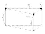
도 13은 일 실시예에 따른 레이저 스캔을 통한 포인트 군집의 수집을 설명하기 위한 도면이다.
도 14는 일 실시예에 따른 입체 공간에 특정 높이를 갖는 레이어를 설명하기 위한 도면이다.
도 15는 일 실시예에 따른 피사체와의 거리에 따른 영상의 해상도 변화를 설명하기 위한 도면이다.
도 16 내지 도 19는 일 실시예에 따른 무인 비행체의 이미지 인지 및 처리를 통한 -비행 제어 및 지상관제 프로세스를 설명하기 위한 도면이다.
도 20은 일 실시예에 따른 구축된 항로의 시뮬레이션을 나타내는 도면이다.
도 21은 일 실시예에 따른 기체 인식 및 항로 관제 형상을 나타내는 도면이다.
도 22는 일 실시예에 따른 라이다(LiDAR)로 스캐닝한 피사체에서 특정 지점의 높이를 추출하는 과정을 설명하기 위한 도면이다.
도 23은 일 실시예에서 사용하는 DSM과 DTM을 설명하기 위한 도면이다.
도 24는 일 실시예에 따라 지상물의 웨이포인트를 설정하는 방법을 설명하기 위한 도면이다.
도 25는 일 실시예에 따라 지상물의 웨이포인트 유효 구간 내에 웨이포인트를 추가하는 과정을 설명하기 위한 도면이다.
도 26은 일 실시예에 따른 무인 비행체의 동작을 나타내는 흐름도이다.
도 27은 다른 실시예에 따른 무인 비행체의 동작을 나타내는 흐름도이다.
도 28은 일 실시예에 따른 무인 비행체 자율비행을 위한 항로 구축 시스템 및 관제 시스템의 운영 방법을 나타내는 흐름도이다.
도 29는 일 실시예에 따라 무인 비행체가 미리 정해진 항로를 비행하는 도중 지상물이 존재할 경우, 지상물에 대한 해상도 높이를 이용하여 미리 설정된 레이어 범위 내에서 비행 고도를 유지를 설명하는 도면이다.
도 30은 다른 실시예에 따른 무인 비행체의 블록 구성도이다.
도 31은 다른 실시예에 따른 무인 비행체 운영 시스템의 운영 방법을 나타내는 흐름도이다.
도 32는 또 다른 실시예에 따른 무인 비행체 운영 시스템의 운영 방법을 나타내는 흐름도이다.
도 33은 또 다른 실시예에 따른 운영 시스템의 무인 비행체 운영 방법을 나타내는 흐름도이다.
도 34는 다른 실시예에 따른 무인 비행체의 동작을 나타내는 흐름도이다.
도 35는 다른 실시예에 따른 관제 시스템의 무인 비행체 관제 방법을 나타내는 흐름도이다.
도 36은 다른 실시예에 따른 운영 시스템의 무인 비행체 운영 방법을 나타내는 흐름도이다.
도 37은 또 다른 실시예에 따른 무인 비행체의 블록 구성도이다.
도 38은 다른 실시예에 따른 무인 비행체, 운영 시스템 및 관제 시스템의 블록 구성을 도시한 도면이다.
도 39는 일 실시예에 따른 무인 비행체의 레이어 간의 자율 비행을 위한 무인 비행체 비행 경로 정보 생성 방법을 나타내는 흐름도이다.
도 40은 다른 실시예에 따른 무인 비행체의 레이어 간의 자율 비행을 위한 무인 비행체 비행 경로 정보 생성 방법을 나타내는 흐름도이다.
도 41은 다른 실시예에 따라 무인 비행체의 레이어간 이동을 위한 항로를 구축하는 무인 비행체 항로 구축 시스템을 나타내는 블록 구성도이다.
도 42는 일 실시예에 따라 레이어 간을 이동하기 위한 무인 비행체의 동작 방법을 나타내는 흐름도이다.
도 43은 다른 실시예에 따라 레이어 간을 이동하기 위한 무인 비행체의 항로를 구축하는 항로 구축 시스템의 블록 구성도이다.
도 44는 일 실시예에 따라 무인 비행체가 레이어간 자율 비행을 수행하는 절차를 설명하기 위한 도면이다.
도 45는 일 실시예에 따라 무인 비행체가 레이어 사이를 이동하기 위하여 설정된 레이어 변경 가능 구간을 설명하는 도면이다.
도 46은 일 실시예에 따라 무인 비행체가 레이어 간을 이동하는 절차를 설명하기 위한 수직 단면도이다.
도 47은 다른 실시예에 따라 무인 비행체가 레이어 간을 이동하는 절차를 설명하는 도면이다.
도 48은 또 다른 실시예에 따라 무인 비행체가 레이어 간을 이동하는 절차를 설명하는 도면이다.
도 49는 또 다른 실시예에 따른 무인 비행체의 레이어 이동을 위한 무인 비행체와 관제 시스템의 방법 흐름도이다.
도 50은 일 실시예에 따른 무인 비행체 제어 방법을 나타내는 흐름도이다.
도 51은 일 실시예에 따른 무인 비행체 제어 시스템을 나타내는 블록도이다.
도 52는 다른 실시예에 따른 무인 비행체 제어 시스템을 나타내는 블록도이다. Figure 1 is a drawing for explaining the flight altitude restrictions for operating an unmanned aerial vehicle.
FIG. 2 is a drawing for explaining a sensor unit of an unmanned aerial vehicle according to one embodiment.
FIG. 3 is a flowchart illustrating a map creation method for unmanned aerial vehicle flight according to one embodiment.
FIG. 4 is a block diagram illustrating a map creation system for unmanned aerial vehicle flight according to one embodiment.
FIGS. 5 and 6 are flowcharts showing a method for establishing an unmanned aerial vehicle route according to one embodiment.
FIG. 7 is a block diagram showing an unmanned aerial vehicle route construction system according to one embodiment.
FIGS. 8 to 10 are diagrams for explaining autonomous flight space shaping from surface scanning and image capturing data according to one embodiment.
FIG. 11 is a diagram for explaining alignment of geospatial data according to one embodiment.
FIG. 12 is a diagram for explaining a method of creating a map by aligning geospatial data according to one embodiment.
FIG. 13 is a diagram illustrating the collection of point clusters through laser scanning according to one embodiment.
FIG. 14 is a drawing for explaining a layer having a specific height in a three-dimensional space according to one embodiment.
FIG. 15 is a drawing for explaining the change in image resolution according to the distance from the subject according to one embodiment.
FIGS. 16 to 19 are diagrams for explaining a flight control and ground control process through image recognition and processing of an unmanned aerial vehicle according to one embodiment.
Figure 20 is a diagram showing a simulation of a constructed route according to one embodiment.
Figure 21 is a drawing showing a gas recognition and route control shape according to one embodiment.
FIG. 22 is a drawing for explaining a process of extracting the height of a specific point on an object scanned by LiDAR according to one embodiment.
Figure 23 is a diagram for explaining the DSM and DTM used in one embodiment.
FIG. 24 is a drawing for explaining a method of setting a waypoint of a ground object according to one embodiment.
FIG. 25 is a diagram for explaining a process of adding a waypoint within a waypoint valid range of a ground object according to one embodiment.
Figure 26 is a flowchart showing the operation of an unmanned aerial vehicle according to one embodiment.
Figure 27 is a flowchart showing the operation of an unmanned aerial vehicle according to another embodiment.
Figure 28 is a flowchart showing an operation method of a route construction system and a control system for autonomous flight of an unmanned aerial vehicle according to one embodiment.
FIG. 29 is a drawing explaining how, when a ground object is present while an unmanned aerial vehicle is flying along a predetermined route according to one embodiment, the flight altitude is maintained within a preset layer range by using a resolution height for the ground object.
Figure 30 is a block diagram of an unmanned aerial vehicle according to another embodiment.
Figure 31 is a flowchart showing an operating method of an unmanned aerial vehicle operating system according to another embodiment.
Figure 32 is a flowchart showing an operating method of an unmanned aerial vehicle operating system according to another embodiment.
Figure 33 is a flowchart showing an unmanned aerial vehicle operation method of an operating system according to another embodiment.
Figure 34 is a flowchart showing the operation of an unmanned aerial vehicle according to another embodiment.
Fig. 35 is a flowchart showing an unmanned aerial vehicle control method of a control system according to another embodiment.
Figure 36 is a flowchart showing an unmanned aerial vehicle operation method of an operating system according to another embodiment.
Figure 37 is a block diagram of an unmanned aerial vehicle according to another embodiment.
FIG. 38 is a block diagram illustrating an unmanned aerial vehicle, an operating system, and a control system according to another embodiment.
FIG. 39 is a flowchart illustrating a method for generating flight path information of an unmanned aerial vehicle for autonomous flight between layers of an unmanned aerial vehicle according to one embodiment.
FIG. 40 is a flowchart illustrating a method for generating flight path information of an unmanned aerial vehicle for autonomous flight between layers of an unmanned aerial vehicle according to another embodiment.
FIG. 41 is a block diagram showing an unmanned aerial vehicle route construction system that constructs a route for inter-layer movement of an unmanned aerial vehicle according to another embodiment.
FIG. 42 is a flowchart illustrating a method of operating an unmanned aerial vehicle for moving between layers according to one embodiment.
Fig. 43 is a block diagram of a route construction system for constructing a route for an unmanned aerial vehicle to move between layers according to another embodiment.
FIG. 44 is a drawing for explaining a procedure for an unmanned aerial vehicle to perform autonomous flight between layers according to one embodiment.
FIG. 45 is a drawing illustrating a layer changeable section set for an unmanned aerial vehicle to move between layers according to one embodiment.
FIG. 46 is a vertical cross-sectional view illustrating a procedure for an unmanned aerial vehicle to move between layers according to one embodiment.
FIG. 47 is a drawing illustrating a procedure for an unmanned aerial vehicle to move between layers according to another embodiment.
FIG. 48 is a drawing illustrating a procedure for an unmanned aerial vehicle to move between layers according to another embodiment.
FIG. 49 is a method flow diagram of an unmanned aerial vehicle and a control system for layer movement of an unmanned aerial vehicle according to another embodiment.
Figure 50 is a flowchart illustrating a method for controlling an unmanned aerial vehicle according to one embodiment.
Figure 51 is a block diagram showing an unmanned aerial vehicle control system according to one embodiment.
Figure 52 is a block diagram showing an unmanned aerial vehicle control system according to another embodiment.
이하, 첨부된 도면을 참조하여 실시예들을 설명한다. 그러나, 기술되는 실시예들은 여러 가지 다른 형태로 변형될 수 있으며, 본 발명의 범위가 이하 설명되는 실시예들에 의하여 한정되는 것은 아니다. 또한, 여러 실시예들은 당해 기술분야에서 평균적인 지식을 가진 자에게 본 발명을 더욱 완전하게 설명하기 위해서 제공되는 것이다. 도면에서 요소들의 형상 및 크기 등은 보다 명확한 설명을 위해 과장될 수 있다.
Hereinafter, embodiments will be described with reference to the attached drawings. However, the described embodiments may be modified in various other forms, and the scope of the present invention is not limited by the embodiments described below. In addition, various embodiments are provided to more completely explain the present invention to a person having average knowledge in the relevant technical field. The shapes and sizes of elements in the drawings may be exaggerated for a clearer description.
도 1은 무인 비행체 운영 비행 고도 제한을 설명하기 위한 도면이다. Figure 1 is a drawing for explaining the flight altitude restrictions for operating an unmanned aerial vehicle.
미항공우주국(NASA)의 무인 항공 시스템 교통 운영(Unmanned Aerial System Traffic Management, UASTM) 계획에 의한 드론 하이웨이(Drone Highway) 구상에 따르면, 드론 하이웨이는 Amazon, Google, NASA, 미국 연방항공청(Federal Aviation Administration, FAA) 등 미국의 약 120여개 관련 기관 및 업체가 참여하는 드론 활용(예, 택배 서비스) 및 관제(예, 충돌 회피 등 안전성 확보를 위한 시스템 구축)에 관한 구상이다. According to the Drone Highway concept of NASA's Unmanned Aerial System Traffic Management (UASTM) plan, the Drone Highway is a concept regarding drone utilization (e.g., delivery service) and control (e.g., building a system to ensure safety such as collision avoidance) with the participation of approximately 120 related organizations and companies in the U.S., including Amazon, Google, NASA, and the Federal Aviation Administration (FAA).
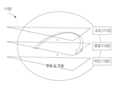
비행금지 구역(110)은 시골, 교외, 도시 지역에서 400ft로부터 500ft까지의 범위에 형성되어 있으나 공항인근은 유인항공기의 이착륙으로 인하여 공항인근의 모든 고도 범위가 비행금지 구역에 포함된다. 일 실시예에 따른 무인 비행체 역시 비행금지 구역에서의 비행은 금지되기에 시골, 교외, 도시 지역의 경우 400ft 이상으로 비행할 수 없다. 그리고 무인 비행체의 수행임무를 기준으로 고속비행 구역(120)과 저속비행 구역(130)으로 구분될 수 있다. 예를 들면, Amazon과 같은 물류 서비스를 제공하는 회사의 경우 신속한 택배서비스를 위해 고속비행구역의 범위를 사용하고 농업, 시설검사, 촬영 등은 저속비행구역의 범위를 사용할 것이다. The no-fly zone (110) is formed in the range of 400 ft to 500 ft in rural, suburban, and urban areas, but the entire altitude range near the airport is included in the no-fly zone due to the takeoff and landing of manned aircraft. According to one embodiment, unmanned aerial vehicles are also prohibited from flying in the no-fly zone, so they cannot fly higher than 400 ft in rural, suburban, and urban areas. In addition, the zone can be divided into a high-speed flight zone (120) and a low-speed flight zone (130) based on the mission performed by the unmanned aerial vehicle. For example, a company providing logistics services such as Amazon will use the range of the high-speed flight zone for quick delivery service, and the range of the low-speed flight zone for agriculture, facility inspection, and photography.
아래의 실시예들에서 각각의 범위에 대한 수직 분리는 "레이어"라는 개념으로 형상화될 수 있으며, 고속비행 구역(120)과 저속비행 구역(130)과 같은 분리는 무인 비행체의 임무수행의 특성(고속으로 배송을 하는 임무 또는 저속으로 천천히 시설물을 검사하는 임무)에 의해 단순히 구분한 것일 뿐, 실제로는 더 다양한 무인 비행체의 임무수행의 특성을 반영하기 위해서 더 많은 레이어가 생성될 수 있다.In the examples below, the vertical separation for each range can be conceptualized as a “layer,” and separations such as a high-speed flight zone (120) and a low-speed flight zone (130) are simply distinguished by the characteristics of the mission execution of the unmanned aerial vehicle (a mission to deliver at high speed or a mission to inspect a facility slowly at low speed). In reality, more layers can be created to reflect more diverse mission execution characteristics of unmanned aerial vehicles.
무인 비행체의 자율비행은 위치좌표(X, Y) 이외에 고도(Z)의 정보를 추가로 요구한다. 기존의 무인 비행체의 자율비행 기술은 고도(Z) 값을 비행 전에 입력하고 전파의 반향 원리를 이용한 초음파 등의 센서에 의해 측정된 고도(Z) 값을 유지한다. 예를 들어 기존 자율비행 체계는 무인 비행체의 조종에 익숙하지 못한 농민들을 대상으로 지표의 높이가 일정한 농경지에 농약살포의 목적으로 활용된다. 그러나 산업수요 변화에 따른 안전 규제(조종사의 가시범위 내 운영)의 한계를 극복하려면 지상물(地上物) 등으로 고도(Z) 값을 일정하게 유지하기 어려운 지역에 대한 보완책이 필요하다. 여기서 지상물(地上物)은 기본으로 지표를 포함하고 지상으로부터 형성 또는 연결 구축된 지물 및 장애물 등을 포함할 수 있다. 전파 고도 센서는 피사체에 대한 반향의 원리로 동작하기 때문에 피사체에 상대적인 고도(Z) 값을 유지하게 된다. 즉, 무인 비행체에 150미터의 고도(Z) 값을 유지하도록 입력됐다면 표고로부터 150미터의 고도가 지속적으로 유지되지만 항로 중간에 50미터 높이의 면적이 넓은 지상물(地上物)이 있다면 해당 지상물(地上物)의 범위 내에서 무인 비행체의 비행 고도는 200미터에서 유지된다. 그래서 비행 고도에 제한이 있을 경우 파장의 반향원리로 고도를 측정하는 전파 센서에 의존한 비행은 결과적으로 안전규제를 위한 비행 고도 제한을 위반할 수 있다. 특히, 도 1에 도시된 바와 같이 비행 고도의 제한은 유인기의 비행 최저 고도로부터 안전거리(수직 분리)를 유지하기 위한 안전조치이기 때문에 이를 위반할 경우 항공추돌사고의 위험이 따른다.Autonomous flight of unmanned aerial vehicles requires altitude (Z) information in addition to location coordinates (X, Y). Existing autonomous flight technology of unmanned aerial vehicles inputs the altitude (Z) value before flight and maintains the altitude (Z) value measured by ultrasonic sensors using the principle of echo of radio waves. For example, existing autonomous flight systems are used for the purpose of spraying pesticides on farmland with a constant ground height, targeting farmers who are not familiar with operating unmanned aerial vehicles. However, in order to overcome the limitations of safety regulations (operation within the pilot's visual range) due to changes in industrial demand, supplementary measures are needed for areas where it is difficult to maintain a constant altitude (Z) value due to ground objects, etc. Here, ground objects basically include the ground, and may include structures and obstacles formed or connected from the ground. Since radio altitude sensors operate on the principle of echo of the subject, they maintain the altitude (Z) value relative to the subject. That is, if an altitude (Z) value of 150 meters is input to an unmanned aerial vehicle, an altitude of 150 meters from the sea level is continuously maintained, but if there is a large ground object with a height of 50 meters in the middle of the route, the flight altitude of the unmanned aerial vehicle is maintained at 200 meters within the range of the ground object. Therefore, if there is a limit to the flight altitude, a flight that depends on a radio sensor that measures the altitude by the principle of wave echo may ultimately violate the flight altitude restrictions for safety regulations. In particular, since the flight altitude restriction as illustrated in Fig. 1 is a safety measure to maintain a safe distance (vertical separation) from the lowest flight altitude of a manned aircraft, violating it may lead to a risk of an aircraft collision.
이에 따라 무인 비행체의 안전한 자율비행을 위해서는 지표로부터 절대적인 고도(Z) 값(즉, 비행 고도 제한)을 유지해야 하고 항로 중간의 지상물(地上物)에 대해 절대적인 고도(Z) 값 유지를 위한 보정이 있어야 하며, 절대적인 고도(Z) 값에 인접하여 수직분리가 어려운 지상물(地上物)에 대한 회피 항로가 제공되어야 한다.
Accordingly, in order to ensure safe autonomous flight of an unmanned aerial vehicle, the absolute altitude (Z) value from the ground (i.e., flight altitude limit) must be maintained, and there must be compensation for maintaining the absolute altitude (Z) value for ground objects in the middle of the route, and an avoidance route must be provided for ground objects that are difficult to vertically separate from the absolute altitude (Z) value.
도 2는 일 실시예에 따른 무인 비행체의 센서부를 설명하기 위한 도면이다. FIG. 2 is a drawing for explaining a sensor unit of an unmanned aerial vehicle according to one embodiment.
도 2를 참조하면, 일 실시예에 따른 무인 비행체의 센서부(200)는 자세 제어부(210), 고장 안전부(220), 및 위치 측정부(230)를 포함할 수 있다. 그리고 무선 통신 센서, 영상 촬영을 위한 센서 및 레이저 스캔 센서 등을 더 포함할 수 있다. Referring to FIG. 2, the sensor unit (200) of the unmanned aerial vehicle according to one embodiment may include an attitude control unit (210), a fail-safe unit (220), and a position measurement unit (230). In addition, it may include a wireless communication sensor, a sensor for image capture, and a laser scan sensor.
자세 제어부(210)는 기체의 회전각도를 감지해 자세를 제어하기 위한 것으로, 예를 들어 자이로 센서(Gyro Sensor), 지자기 센서(Geo Magnetic Sensor), 가속기(Accelerator) 등이 사용될 수 있다. The attitude control unit (210) detects the rotation angle of the aircraft to control the attitude, and for example, a gyro sensor, a geomagnetic sensor, an accelerator, etc. can be used.
고장 안전부(220)는 비행 오류(Falt Safe)를 위한 것으로, 예를 들어 기압 고도계(전파 고도 센서), 초음파, 레이더, 전압, 전류 측정계 등이 사용될 수 있다. The fail-safe unit (220) is for flight errors (Falt Safe), and for example, a barometric altimeter (radio altitude sensor), ultrasonic waves, radar, voltage, current measuring meters, etc. can be used.
한편, 전파 고도 센서는 피사체에 대한 반향의 원리로 동작하기 때문에 피사체에 상대적인 고도(Z) 값을 유지하게 된다. 그래서 비행 고도에 제한이 있을 경우 파장의 반향원리로 고도를 측정하는 전파 센서에 의존한 비행은 결과적으로 안전규제를 위한 비행 고도 제한을 위반할 수 있다. 이에 따라 무인 비행체의 안전한 자율비행을 위해서는 지표로부터 절대적인 고도(Z) 값(즉, 비행 고도 제한)을 유지해야 하고 항로 중간의 지상물(地上物)에 대해 절대적인 고도(Z) 값 유지를 위한 보정이 있어야 하며, 절대적인 고도(Z) 값에 인접하여 수직분리가 어려운 지상물(地上物)에 대한 회피 항로가 제공되어야 한다. Meanwhile, since the radio altitude sensor operates on the principle of echo of the subject, it maintains the altitude (Z) value relative to the subject. Therefore, if there is a limit to the flight altitude, a flight dependent on a radio sensor that measures the altitude by the principle of echo of the wave may end up violating the flight altitude limit for safety regulations. Accordingly, in order to ensure safe autonomous flight of an unmanned aerial vehicle, the absolute altitude (Z) value from the ground (i.e., the flight altitude limit) must be maintained, and there must be compensation for maintaining the absolute altitude (Z) value for ground objects in the middle of the route, and an avoidance route must be provided for ground objects that are difficult to vertically separate from the absolute altitude (Z) value.
위치 측정부(230)는 무인 비행체의 위치를 감지하는 센서로, 예컨대 GPS(Global Positioning System) 센서 등이 사용될 수 있다. The position measuring unit (230) is a sensor that detects the position of an unmanned aerial vehicle, and for example, a GPS (Global Positioning System) sensor can be used.
한편, GPS 센서를 이용하여 고도 측정을 하는 경우 고도(Z) 값 산출의 한계를 전제로 오차 범위를 주변 인프라를 통해 줄여야 한다. 그러나 GPS 고도 측정은 GPS 위성의(기하학적) 배치 상태에 1차 영향을 받고 지상 장애물 및 지형에 2차 영향을 받기 때문에 고도(Z) 값 산출이 불가능 하거나 동일 지점에서도 오차가 발생할 수 있다. On the other hand, when measuring altitude using a GPS sensor, the error range must be reduced through surrounding infrastructure, assuming the limitation of calculating altitude (Z) values. However, GPS altitude measurement is primarily affected by the (geometric) arrangement of GPS satellites and is secondarily affected by ground obstacles and terrain, so altitude (Z) value calculation may be impossible or errors may occur even at the same point.
일 실시예에 따르면 실제 비행을 통한 항로 상의 고도(Z) 값 추출을 위해 먼저, 입체 공간에 2D 레이어(Layer)의 구축에 필요한 라이다(LiDAR) 스캐닝으로 추출한 피사체의 포인트 군집(Point Cloud)을 분석할 수 있다. In one embodiment, to extract the altitude (Z) value on the route through an actual flight, first, a point cloud of the subject extracted by LiDAR scanning necessary for constructing a 2D layer in a three-dimensional space can be analyzed.
전파 또는 빛의 반향으로부터 추출된 포인트 군집의 분석을 통해 피사체 특정 점의 높이 값을 연결하여 얻은 최초 레이어는 전파간섭이나 피사체의 재질 및 입사각에 의해 발생하는 왜곡(예컨대, 전파 음영 등)에 의해 발생한 오차를 배제할 수 없다. 그래서 추출 값의 검정 및 보정을 통해 보다 안전한 자율비행 항로를 구축할 수 있다.
The first layer obtained by connecting the height values of specific points of the subject through analysis of point clusters extracted from radio waves or light echoes cannot exclude errors caused by radio interference or distortions (e.g., radio shadows) caused by the material of the subject and the angle of incidence. Therefore, a safer autonomous flight route can be established through verification and correction of the extracted values.
도 3은 일 실시예에 따른 무인 비행체 비행을 위한 지도 제작 방법을 나타내는 흐름도이다. FIG. 3 is a flowchart illustrating a map creation method for unmanned aerial vehicle flight according to one embodiment.
도 3을 참조하면, 일 실시예에 따른 무인 비행체 비행을 위한 지도 제작 방법은 지표 스캐닝 데이터로부터 피사체를 식별하여 자율비행이 가능한 공간을 레이어(Layer)로 형상화하는 단계(310), 및 공간에 형상화된 레이어에 비행 고도 제한 데이터, 정밀수치 지도, 및 군사보안지역 또는 비행금지 구역을 회피하는 항로 정보 중 적어도 어느 하나 이상을 정합하여 공간에 무인 비행체의 비행을 위한 자율항법 지도를 구축하는 단계(320)를 포함하여 이루어질 수 있다. 여기에서 레이어(Layer)는 3차원 공간에 고도 값(높이 값)을 적용하여 형상화한 2차원 공간을 의미할 수 있다.Referring to FIG. 3, a method for creating a map for an unmanned aerial vehicle flight according to one embodiment may include a step (310) of identifying a subject from ground scanning data and forming a space in which autonomous flight is possible into a layer, and a step (320) of constructing an autonomous navigation map for the flight of an unmanned aerial vehicle in the space by aligning at least one of flight altitude restriction data, a precision numerical map, and route information for avoiding a military security area or a no-fly zone to the layer formed in the space. Here, the layer may mean a two-dimensional space formed by applying an altitude value (height value) to a three-dimensional space.
여기서 자율비행이 가능한 공간을 레이어로 형상화하는 단계는, 지표 촬영 항공기에 탑재된 지표 스캐닝 장치에 의해 스캐닝된 피사체의 포인트 군집(Point Cloud)을 획득하는 단계, 수집된 포인트 군집을 분석하여 피사체를 식별하는 단계, 지형 고도 데이터를 활용하여 식별된 피사체의 특정 지점의 높이 값을 추출하는 단계, 및 추출된 피사체의 특정 지점의 높이 값을 연결하여 공간에 무인 비행체의 자율비행이 가능한 면적과 고도를 레이어로 형상화하는 단계를 포함할 수 있다. Here, the step of shaping a space in which autonomous flight is possible into a layer may include a step of acquiring a point cloud of a subject scanned by a ground scanning device mounted on a ground photographing aircraft, a step of analyzing the collected point cloud to identify the subject, a step of extracting a height value of a specific point of the identified subject using terrain elevation data, and a step of shaping an area and altitude in which autonomous flight of an unmanned aerial vehicle is possible into a layer by connecting the height values of the specific points of the extracted subject.
또한 레이어에 구축된 무인 비행체의 비행을 위한 자율항법 지도를 GPS 또는 위치좌표 보정 장치의 정보를 통해 기 설정된 안전 기준 내에서 무인 비행체와 동기화시켜 무인 비행체에 적용 가능한 공간 지도로 형상화하는 단계(330)를 더 포함하여 이루어질 수 있다. In addition, the step (330) of synchronizing an autonomous navigation map for the flight of an unmanned aerial vehicle built on a layer with the unmanned aerial vehicle within a preset safety standard through information from a GPS or position coordinate correction device and shaping it into a spatial map applicable to the unmanned aerial vehicle can be further included.
일 실시예들에 따르면 비가시권의 자율비행 지도를 제공하여 지상물(地上物) 등으로 고도 값을 일정하게 유지하기 어려운 지역에 대한 조종사의 가시 범위 내 운영의 한계를 극복할 수 있다. According to some embodiments, by providing a non-visual autonomous flight map, it is possible to overcome the limitations of operating within a pilot's visual range in areas where it is difficult to maintain a constant altitude value due to ground objects, etc.
또한 지표 스캐닝 및 영상 촬영 데이터로부터 자율비행 공간을 레이어로 형상화하고 형상화된 레이어에 데이터를 정합하여 고도 값이 반영된 무인 비행체 비행을 위한 지도 제작 방법 및 시스템을 제공할 수 있다. In addition, a method and system for producing a map for unmanned aerial vehicle flight can be provided by shaping an autonomous flight space into layers from surface scanning and image capturing data and aligning data to the shaped layers to reflect altitude values.
다른 측면에 따르면, 무인 비행체 비행을 위한 지도 제작 방법은 무인 비행체에 대한 임무에 따라 무인 비행체가 비행할 수 있는 지표면으로부터 일정 고도 값을 갖는 레이어를 설정하는 단계, 설정된 레이어 상에서 무인 비행체의 항로를 설정하는 단계, 및 설정된 레이어와 항로를 포함하는 자율 항법 지도를 구축하는 단계를 포함할 수 있다. 여기서, 항로는 항로의 지표면에 존재하는 지상물의 위치를 포함하는 적어도 둘 이상의 웨이포인트들로 구성될 수 있다. 그리고 무인 비행체의 식별 정보에 따라 임무 별 자율 항법 지도를 구축하는 단계를 더 포함할 수도 있다. 웨이포인트는 무인 비행체에게 할당된 임무를 수행할 수 있는 지점이다.이에 따라 비가시권의 자율비행 지도를 제공하여 지상물(地上物) 등으로 고도 값을 일정하게 유지하기 어려운 지역에 대한 조종사의 가시 범위 내 운영의 한계를 극복할 수 있다. 또한, 지표 스캐닝 및 영상 촬영 데이터로부터 자율비행 공간을 레이어로 형상화하고 형상화된 레이어에 데이터를 정합하여 고도 값이 반영된 무인 비행체 비행을 위한 지도 제작 방법 및 시스템을 제공할 수 있다.According to another aspect, a method for creating a map for an unmanned aerial vehicle flight may include a step of setting a layer having a certain altitude value from the ground surface over which the unmanned aerial vehicle can fly according to a mission for the unmanned aerial vehicle, a step of setting a route for the unmanned aerial vehicle on the set layer, and a step of constructing an autonomous navigation map including the set layer and the route. Here, the route may be composed of at least two waypoints including the positions of ground objects existing on the ground surface of the route. And the method may further include a step of constructing an autonomous navigation map for each mission according to identification information of the unmanned aerial vehicle. A waypoint is a point where the assigned mission can be performed by the unmanned aerial vehicle. Accordingly, an autonomous flight map of a non-visible area can be provided to overcome the limitations of operation within the pilot's visible range in an area where it is difficult to maintain a constant altitude value due to ground objects, etc. In addition, a method and system for creating a map for an unmanned aerial vehicle flight in which an autonomous flight space is visualized as a layer from ground scanning and image capturing data and data is aligned to the visualized layer can be provided.
아래에서 일 실시예에 따른 무인 비행체 비행을 위한 지도 제작 방법의 각 단계에 대해 더 구체적으로 설명한다.
Below, each step of the map creation method for unmanned aerial vehicle flight according to one embodiment is described in more detail.
도 4는 일 실시예에 따른 무인 비행체 비행을 위한 지도 제작 시스템을 나타내는 블록도이다. 도 4에 도시된 바와 같이 일 실시예에 따른 무인 비행체 비행을 위한 지도 제작 시스템은 레이어 형상화부(410), 자율항법 지도부(420), 및 공간 지도부(430)를 포함하여 이루어질 수 있다. 이러한 무인 비행체 비행을 위한 지도 제작 시스템의 각 구성요소들은 서버에 포함된 프로세서일 수 있다. Fig. 4 is a block diagram showing a map production system for unmanned aerial vehicle flight according to one embodiment. As shown in Fig. 4, the map production system for unmanned aerial vehicle flight according to one embodiment may include a layer shaping unit (410), an autonomous navigation map unit (420), and a space map unit (430). Each component of the map production system for unmanned aerial vehicle flight may be a processor included in a server.
이러한 구성요소들은 도 3의 방법이 포함하는 단계들(310 내지 330)을 메모리가 포함하는 운영체제와 적어도 하나의 프로그램 코드를 통해 실행하도록 구현될 수 있다. These components can be implemented to execute steps (310 to 330) included in the method of FIG. 3 through an operating system including a memory and at least one program code.
단계(310)에서 레이어 형상화부(410)는 지표 스캐닝 데이터로부터 피사체를 식별하여 자율비행이 가능한 공간을 레이어(Layer)로 형상화할 수 있다. 여기에서 레이어(Layer)는 높이 개념을 포함하는 평면으로 나타낼 수 있다. In step (310), the layer shaping unit (410) can identify a subject from ground scanning data and shape a space in which autonomous flight is possible into a layer. Here, the layer can be expressed as a plane including a height concept.
레이어 형상화부(410)는 공간에 다수의 2차원 레이어들을 생성할 수 있으며, 상기의 레이어들은 수직 분리를 형성할 수 있다.The layer shaping unit (410) can create a number of two-dimensional layers in space, and the layers can form a vertical separation.
여기서 레이어 형상화부(410)는 수집부, 식별부, 추출부, 및 레이어부를 포함할 수 있다. Here, the layer shaping unit (410) may include a collection unit, an identification unit, an extraction unit, and a layer unit.
레이어 형상화부(410)의 수집부는 지표 촬영 항공기에 탑재된 지표 스캐닝 장치에 의해 스캐닝된 피사체의 포인트 군집(Point Cloud)을 획득할 수 있다. 이때 피사체의 획득된 포인트 군집을 사용하여 건물의 특정 지점의 높이를 추출할 수 있는데, 이때의 높이는 건물의 꼭대기 높이일 수도 있으며 건물의 중간 높이 등 건물의 특정 지점의 높이가 될 수 있다. 일 실시예에 따라 스캐닝된 피사체의 포인트 군집에서 건물의 특정 지점의 높이를 추출하는 방법을 도 22를 통해 설명하기로 한다. The collection unit of the layer shaping unit (410) can obtain a point cloud of a subject scanned by a ground scanning device mounted on a ground photographing aircraft. At this time, the obtained point cloud of the subject can be used to extract the height of a specific point of a building. The height at this time can be the top height of the building or the height of a specific point of the building, such as the middle height of the building. According to one embodiment, a method of extracting the height of a specific point of a building from a point cloud of a scanned subject will be described with reference to FIG. 22.
도 22는 일 실시예에 따라 라이다(LiDAR)로 스캐닝한 피사체에서 특정 지점의 높이를 추출하는 과정을 설명하기 위한 도면으로, 도 22의 (a)는 실제 피사체의 이미지이며, (b)는 실제 피사체를 라이다(LiDAR) 장비와 같은 스캐닝 장치를 통해 스캐닝된 피사체의 포인트 군집을 나타낸다. 이때 피사체의 각 지점에서의 높이(Height)를 참조할 수 있는 컬러 스펙트럼(2200)을 나타낼 수 있다. 일 실시예에 따라 레이어 형상화부(410)의 수집부는 스캐닝된 피사체의 특정 지점의 높이를 상기 컬러 스펙트럼을 참조하여 추출할 수가 있다. FIG. 22 is a drawing for explaining a process of extracting the height of a specific point in a subject scanned by LiDAR according to one embodiment. FIG. 22 (a) is an image of an actual subject, and (b) shows a point cluster of the subject scanned by a scanning device such as LiDAR equipment. At this time, a color spectrum (2200) that can refer to the height at each point of the subject can be shown. According to one embodiment, the collection unit of the layer shaping unit (410) can extract the height of a specific point of the scanned subject by referring to the color spectrum.
일 실시예에서 포인트 군집(Point Cloud)를 사용하여 스캐닝된 피사체로부터 특정 지점의 높이를 추출할 때, 컬러 스펙트럼(2200)의 높이 스펙트럼 값을 이용할 수 있다. 하지만, 라이다(LiDAR)는 레이저 빛의 펄스(Pulse) 방식으로 피사체를 스캐닝하기 때문에 피사체의 재질에 따른 빛의 분산, 경계 및 불연속선(Breakline)의 인식문제가 발생할 수 있고 컬러 스펙트럼(2200)을 분석하기 위해 사용하는 소프트웨어 툴의 알고리즘에 따라 피사체 높이 값에 대한 추출 결과가 달라질 수 있다. 따라서, 일 실시예에서는 처음에 라이다(LiDAR) 데이터인 포인트 군집(Point Cloud)에 의해 설정된 레이어에 대해 초도 비행 - 조종사의 가시권 비행 - 에 의한 레이어의 높이 검증을 광학 영상 장치의 캘리블레이션(Calibration)을 통해 레이어의 오차를 보정할 수 있다. In one embodiment, when extracting the height of a specific point from a scanned subject using a point cloud, the height spectrum value of the color spectrum (2200) can be used. However, since LiDAR scans the subject in a pulse manner of laser light, problems in recognizing light dispersion, boundaries, and breaklines depending on the material of the subject may occur, and the extraction result for the subject height value may vary depending on the algorithm of the software tool used to analyze the color spectrum (2200). Therefore, in one embodiment, for a layer initially set by a point cloud, which is LiDAR data, an error in the layer can be corrected through calibration of an optical imaging device by verifying the height of the layer by an initial flight - a flight within the pilot's line of sight.
예컨대 레이어 형상화부(410)의 수집부는 지표 촬영 항공기에 탑재된 라이다(LiDAR) 장치를 통해 라이다 펄스가 투사된 피사체의 포인트 군집을 획득할 수 있다.For example, the collection unit of the layer shaping unit (410) can obtain a point cluster of an object on which a LiDAR pulse is projected through a LiDAR device mounted on a ground photographing aircraft.
레이어 형상화부(410)의 식별부는 수집부에서 수집된 포인트 군집을 분석하여 피사체를 식별할 수 있다. 이때 레이어 형상화부(410)의 식별부는 포인트 군집을 통해 지상물 객체의 경계 또는 윤곽을 인식할 수 있고, 이를 통해 식별된 지상물 객체에 대해 교량, 빌딩, 전선 등으로 식별할 수 있다.The identification unit of the layer shaping unit (410) can identify a subject by analyzing a point cluster collected from the collection unit. At this time, the identification unit of the layer shaping unit (410) can recognize the boundary or outline of a ground object through the point cluster, and can identify the ground object identified through this as a bridge, building, wire, etc.
레이어 형상화부(410)의 추출부는 지형 고도 데이터들 중 수치 표면 모형(Digital Surface Model, DSM)이나 수치 지형 모델(Digital Terrain Model, DTM)을 활용하여 식별부에서 식별된 피사체의 특정 지점의 높이 값을 추출할 수 있다. 상기 DSM 데이터와 DTM 데이터는 각 국가의 지리 정보를 데이터베이스화 하여 구축하고 있는 정부 기관(예컨대, 한국의 경우에는 국토지리정보원)이나 항공측량 회사로부터 획득될 수 있는 데이터이다. 도 23은 일 실시예에서 사용하는 DSM과 DTM을 설명하기 위한 도면으로, 도 23에 도시된 바와 같이 DSM은 지상물(地上物)의 높이 값이고 DTM은 지형의 높이 값(표고)이 될 수 있다.The extraction unit of the layer shaping unit (410) can extract the height value of a specific point of the subject identified in the identification unit by utilizing a digital surface model (DSM) or a digital terrain model (DTM) among the terrain elevation data. The DSM data and the DTM data can be acquired from a government agency (for example, the National Geographic Information Institute in the case of Korea) or an aerial surveying company that is constructing a database of geographic information of each country. FIG. 23 is a drawing for explaining the DSM and DTM used in one embodiment, and as illustrated in FIG. 23, the DSM can be a height value of a ground object and the DTM can be a height value (elevation) of the terrain.
레이어 형상화부(410)의 레이어부는 추출부에서 추출된 피사체의 특정 지점의 높이 값을 연결하여 공간 에 무인 비행체의 자율비행이 가능한 면적과 고도를 레이어로 형상화할 수 있다. The layer section of the layer shaping section (410) can shape the area and altitude in space where an unmanned aerial vehicle can fly autonomously as a layer by connecting the height values of specific points of the subject extracted from the extraction section.
이러한 피사체를 식별하여 자율비행 공간을 형상화하는 방법을 아래에서 도 8 내지 도 10을 참조하여 예를 들어 설명하기로 한다. A method of identifying such subjects and shaping an autonomous flight space will be described below with examples referring to FIGS. 8 to 10.
단계(320)에서 자율항법 지도부(420)는 공간에 형상화된 레이어에 비행 고도 제한 데이터, 정밀수치 지도, 및 군사보안지역 또는 비행금지 구역을 회피하는 항로 정보 중 적어도 어느 하나 이상을 정합하여 공간에 무인 비행체의 비행을 위한 자율항법 지도를 구축할 수 있다. In step (320), the autonomous navigation guidance unit (420) can build an autonomous navigation map for the flight of an unmanned aerial vehicle in space by aligning at least one of flight altitude restriction data, a precision numerical map, and route information for avoiding military security areas or no-fly zones to a layer visualized in space.
단계(330)에서 공간 지도부(430)는 레이어에 구축된 무인 비행체의 비행을 위한 자율항법 지도를 GPS 또는 위치좌표 보정 장치의 정보를 통해 기 설정된 안전 기준 내에서 무인 비행체와 동기화시켜 무인 비행체에 적용 가능한 공간 지도로 형상화할 수 있다. In step (330), the space management unit (430) can synchronize the autonomous navigation map for the flight of the unmanned aerial vehicle built in the layer with the unmanned aerial vehicle within the preset safety standards through information from a GPS or position coordinate correction device, and shape it into a space map applicable to the unmanned aerial vehicle.
공간 지도부(430)는 레이어에 구축된 무인 비행체의 비행을 위한 자율항법 지도에 GPS 좌표를 정합하고, 무인 비행체의 비행을 위한 자율항법 지도로부터 지상물(地上物) 이미지의 고도 값을 처리하여 센서 측정 고도 값을 보정할 수 있다.The space map (430) can align GPS coordinates with an autonomous navigation map for the flight of an unmanned aerial vehicle built in a layer, and process the altitude value of an image of a ground object from the autonomous navigation map for the flight of an unmanned aerial vehicle to correct the sensor measured altitude value.
즉, 공간 지도부(430)는 레이어에 구축된 무인 비행체의 비행을 위한 자율항법 지도에 GPS 좌표를 정합하고, 상기 자율항법 지도로부터 정합된 GPS 좌표에 무인 비행체에 탑재된 영상촬영 장치(예, 탑재가 가능한 각종 광학(Optic)기반 영상촬영 장치)의 설정(지표 기준으로 캘리브레이션)된 입사각에 의한 지상물(地上物)의 해상도 변화 분석을 수행하고, 해상도 변화 분석을 통해 추출된 해상도의 높이 값을 GPS 좌표에 정합하여 초음파 등 반향의 원리를 사용하는 고도 측정 장치의 고도 측정값을 보정할 수 있다.That is, the space map (430) aligns GPS coordinates with an autonomous navigation map for the flight of an unmanned aerial vehicle built on a layer, analyzes changes in the resolution of ground objects by the set (calibrated with respect to the ground) incidence angle of an imaging device (e.g., various optical-based imaging devices that can be mounted) mounted on the unmanned aerial vehicle based on the GPS coordinates aligned from the autonomous navigation map, and corrects the altitude measurement value of an altitude measurement device that uses the principle of echo, such as ultrasonic waves, by aligning the height value of the resolution extracted through the analysis of the change in resolution with the GPS coordinates.
이러한 지리공간 데이터의 정합과 지도를 구축하는 방법을 아래에서 도 11 및 도 12를 참조하여 예를 들어 더 구체적으로 설명하기로 한다.
The method of aligning such geospatial data and constructing a map will be explained in more detail with examples below, referring to Figures 11 and 12.
다른 실시예에 따른 입체 정밀 지도에 무인 비행체 비행을 위한 지도 제작 방법에 있어서, 입체 정밀 지도에 다수의 레이어가 수직 분리를 형성하는 단계, 및 수직 분리의 분리 간격에 형성되는 항로와 레이어에 형성되는 수집된 웨이포인트(Way Point)를 나타내는 심벌(Symbol)을 형상화하는 단계를 포함하여 이루어질 수 있다. In another embodiment, a method for producing a map for an unmanned aerial vehicle flight on a three-dimensional precision map may be provided, the method including the steps of forming a plurality of layers in a three-dimensional precision map to form vertical separations, and the steps of shaping symbols representing routes formed at separation intervals of the vertical separations and collected waypoints formed in the layers.
여기서 다수의 레이어가 수직 분리를 형성하는 단계는 지표 촬영 항공기에 탑재된 지표 스캐닝 장치에 의해 스캐닝된 피사체의 포인트 군집(Point Cloud)을 획득하는 단계, 수집된 포인트 군집을 분석하여 피사체를 식별하는 단계, 지형 고도 데이터를 활용하여 식별된 피사체의 특정 지점의 높이 값을 추출하는 단계, 및 추출된 피사체의 특정 지점의 높이 값을 연결하여 공간에 무인 비행체의 자율비행이 가능한 면적과 고도를 레이어로 형상화하는 단계를 포함할 수 있다.Here, the step of forming a plurality of layers to form a vertical separation may include the step of acquiring a point cloud of a subject scanned by a ground scanning device mounted on a ground photographing aircraft, the step of analyzing the collected point cloud to identify the subject, the step of extracting a height value of a specific point of the identified subject using terrain elevation data, and the step of connecting the height values of the specific points of the extracted subject to form an area and altitude in space where autonomous flight of the unmanned aerial vehicle is possible as a layer.
다른 실시예에 따른 입체 정밀 지도에 무인 비행체 비행을 위한 지도 제작 방법은 다른 실시예에 따른 입체 정밀 지도에 무인 비행체 비행을 위한 지도 제작 시스템을 이용하여 더 구체적으로 설명할 수 있다. 여기서 입체 정밀 지도에 무인 비행체 비행을 위한 지도 제작 시스템은 레이어 형상화부와, 항로 및 심벌 형상화부를 포함하여 이루어질 수 있다. 이러한 입체 정밀 지도에 무인 비행체 비행을 위한 지도 제작 시스템의 각 구성요소들은 서버에 포함되는 프로세서일 수 있다. A method for producing a map for an unmanned aerial vehicle flight on a three-dimensional precision map according to another embodiment can be described more specifically using a map producing system for an unmanned aerial vehicle flight on a three-dimensional precision map according to another embodiment. Here, the map producing system for an unmanned aerial vehicle flight on a three-dimensional precision map can include a layer shaping unit and a route and symbol shaping unit. Each component of the map producing system for an unmanned aerial vehicle flight on a three-dimensional precision map can be a processor included in a server.
레이어 형상화부(410)는 입체 정밀 지도에 다수의 레이어들을 수직 분리하여 형성할 수 있다. 이때 입체 정밀 지도는 기존의 입체 정밀 지도를 사용하거나 데이터를 수집하여 직접 제작할 수 있다. The layer shaping unit (410) can form multiple layers by vertically separating them on a three-dimensional precision map. At this time, the three-dimensional precision map can be produced directly by using an existing three-dimensional precision map or by collecting data.
레이어 형상화부(410)는, 도 4에서 설명한 바와 같이, 수집부, 식별부, 추출부, 및 레이어부를 포함할 수 있다. The layer shaping unit (410) may include a collection unit, an identification unit, an extraction unit, and a layer unit, as described in FIG. 4.
레이어 형상화부(410)의 수집부는 지표 촬영 항공기에 탑재된 지표 스캐닝 장치에 의해 스캐닝된 피사체의 포인트 군집(Point Cloud)을 획득할 수 있다. 예컨대 레이어 형상화부의 수집부는 지표 촬영 항공기에 탑재된 라이다(LiDAR) 장치를 통해 라이다 펄스가 투사된 피사체의 포인트 군집을 획득할 수 있다.The collection unit of the layer shaping unit (410) can obtain a point cloud of a subject scanned by a ground scanning device mounted on a ground photographing aircraft. For example, the collection unit of the layer shaping unit can obtain a point cloud of a subject projected with a LiDAR pulse by a LiDAR device mounted on a ground photographing aircraft.
레이어 형상화부(410)의 식별부는 수집부에서 수집된 포인트 군집을 분석하여 피사체를 식별할 수 있다. The identification unit of the layer shaping unit (410) can identify a subject by analyzing a point cluster collected from the collection unit.
레이어 형상화부(410)의 추출부는 지형 고도 데이터들 중 수치 표면 모형(Digital Surface Model, DSM)이나 수치 표고 모델(Digital Terrain Model, DTM)을 활용하여 식별부에서 식별된 피사체의 특정 지점의 높이 값을 추출할 수 있다. The extraction unit of the layer shaping unit (410) can extract the height value of a specific point of an object identified in the identification unit by utilizing a digital surface model (DSM) or a digital terrain model (DTM) among the terrain elevation data.
레이어 형상화부(410)의 레이어부는 추출부에서 추출된 피사체의 특정 지점의 높이 값을 연결하여 공간에 무인 비행체의 자율비행이 가능한 면적과 고도를 레이어로 형상화할 수 있다. The layer section of the layer shaping section (410) can shape the area and altitude where an unmanned aerial vehicle can autonomously fly in space as a layer by connecting the height values of specific points of the subject extracted from the extraction section.
여기서 레이어는 형성 고도, 수행 가능 미션, 기체 제원 중 적어도 어느 하나 이상의 정보를 포함할 수 있다.Here, a layer may contain at least one of the following information: formation altitude, performable missions, and aircraft specifications.
그리고 레이어에 형성된 항로의 심벌은 위치 좌표와 해당 좌표에 대한 레이어를 기준으로 한 이미지의 고도 값이 포함되며, 이미지의 고도 값은 무인 비행체가 자율비행 중인 레이어의 형성 고도를 유지하기 위해 고도를 측정하는 센서에 의한 측정값을 보정해야 하는 값이 될 수 있다.
And the symbol of the route formed in the layer includes the position coordinates and the altitude value of the image based on the layer for the corresponding coordinates, and the altitude value of the image may be a value that must be corrected for the measurement value by the altitude measuring sensor to maintain the formation altitude of the layer in which the unmanned aerial vehicle is flying autonomously.
도 5 및 도 6은 일 실시예에 따른 무인 비행체 항로 구축 방법을 나타내는 흐름도이다. FIGS. 5 and 6 are flowcharts showing a method for establishing an unmanned aerial vehicle route according to one embodiment.
도 5 및 도 6을 참조하면, 일 실시예에 따른 무인 비행체 항로 구축 방법은 지표 스캐닝 데이터로부터 피사체를 식별하여 자율비행이 가능한 공간을 레이어(Layer)로 형상화하는 단계(510), 형상화된 레이어로부터 비행 경로에 대한 지표 영상 데이터를 수집하는 단계(520), 및 수집된 지표 영상 데이터를 통해 지표면을 스캐닝한 카메라와 피사체와의 거리에 따른 영상 해상도 변화를 분석하여 비행 항로 상의 고도 값을 추출하는 단계(530)를 포함하여 이루어질 수 있다. 여기에서 카메라와 피사체와의 거리는 카메라의 캘리브레이션(calibration)을 통해 확인된 카메라의 내부 파라미터 값과 외부 파라미터 값들을 통해 계산될 수 있다. 또한 본 발명이 적용되는 실시예에서는 지상물(地上物)의 이미지를 촬영할 당시의 카메라의 위치 및 방향을 알고 있다고 가정하므로, 상술한 카메라의 파라미터들을 고려함으로써 카메라와 피사체와의 거리를 계산할 수 있다. Referring to FIGS. 5 and 6, a method for constructing an unmanned aerial vehicle route according to an embodiment may include a step (510) of identifying a subject from ground scanning data and shaping a space in which autonomous flight is possible into a layer, a step (520) of collecting ground image data for a flight path from the shaped layer, and a step (530) of analyzing a change in image resolution according to the distance between a camera that scans the ground surface and the subject through the collected ground image data to extract an altitude value on the flight path. Here, the distance between the camera and the subject can be calculated through internal and external parameter values of the camera confirmed through camera calibration. In addition, in an embodiment to which the present invention is applied, it is assumed that the position and direction of the camera at the time of capturing an image of a ground object are known, and therefore the distance between the camera and the subject can be calculated by considering the parameters of the camera described above.
또한 카메라는 피사체의 해상도 변화를 분석할 수 있는 집광부, 집광조절부, 촬상부의 구조를 갖는 일반적인 광학(Optic) 카메라뿐 아니라 캘리브레이션(calibration)의 파라미터 값에 기준하여 피사체의 해상도 변화를 인지하고 기록할 수 있는 다른 치환 가능한 장치도 포함할 수 있다.In addition, the camera may include not only a general optical camera having a structure of a light collection unit, a light collection control unit, and an imaging unit capable of analyzing changes in the resolution of a subject, but also other replaceable devices capable of recognizing and recording changes in the resolution of a subject based on parameter values of calibration.
여기서 자율비행이 가능한 공간을 레이어로 형상화하는 단계(510)는, 지표 촬영 항공기에 탑재된 지표 스캐닝 장치에 의해 스캐닝된 피사체의 포인트 군집(Point Cloud)을 획득하는 단계(511), 수집된 포인트 군집을 분석하여 피사체를 식별하는 단계(512), 지형 고도 데이터를 활용하여 식별된 피사체의 특정 지점의 높이 값을 추출하는 단계(513), 및 추출된 피사체의 특정 지점의 높이 값을 연결하여 공간에 무인 비행체의 자율비행이 가능한 면적과 고도를 레이어로 형상화하는 단계(514)를 포함할 수 있다. Here, the step (510) of shaping a space in which autonomous flight is possible into layers may include a step (511) of acquiring a point cloud of a subject scanned by a ground scanning device mounted on a ground photographing aircraft, a step (512) of identifying a subject by analyzing the collected point cloud, a step (513) of extracting a height value of a specific point of the identified subject by utilizing terrain elevation data, and a step (514) of shaping an area and altitude in which autonomous flight of an unmanned aerial vehicle is possible into layers by connecting the height values of the specific points of the extracted subject.
또한, 일 실시예에 따른 무인 비행체 항로 구축 방법은 추출된 고도 값으로부터 항로 검증을 통해 전파 고도 센서의 측정값을 보정하는 단계(540)를 더 포함하여 이루어질 수 있다. In addition, the method for establishing an unmanned aerial vehicle route according to one embodiment may further include a step (540) of correcting a measurement value of a radio altitude sensor through route verification from an extracted altitude value.
일 실시예들에 따르면 비가시권의 자율비행 항로를 제공하여 지상물(地上物) 등으로 고도 값을 일정하게 유지하기 어려운 지역에 대한 조종사의 가시 범위 내 운영의 한계를 극복할 수 있다. According to some embodiments, an autonomous flight route beyond the visual line of sight can be provided to overcome the limitations of operation within the pilot's visual range in areas where it is difficult to maintain a constant altitude value due to ground objects, etc.
또한 스캐닝 데이터를 이용하여 표고 및 장애물의 높이 정보를 추출하고, 지표 영상 데이터의 영상 해상도 변화를 분석하여 추출된 지상물(地上物) 높이 정보를 활용하여 캘리브레이션(Calibration) 검증과 무인 비행체의 전파 고도 센서의 측정값을 보정함으로써, 무인 비행체의 안전 자율비행 항로를 구축하는 무인 비행체 항로 구축 방법 및 시스템을 제공할 수 있다. In addition, by extracting elevation and obstacle height information using scanning data, analyzing changes in image resolution of ground image data, and utilizing the extracted ground object height information to verify calibration and correct the measurement values of the radio altitude sensor of the unmanned aerial vehicle, a method and system for constructing a safe autonomous flight route for the unmanned aerial vehicle can be provided.
일 실시예에 따른 캘리브레이션 검증은 무인 비행체에 장착된 카메라 렌즈와 피사체와의 거리, 피사체와의 초점이 정확한지에 대한 검증을 수행하는 것을 포함하며, 무인 비행체의 전파 고도 센서의 측정값의 보정은 전파 고도 센서가 가진 오차 범위를 영상 해상도 변화 값을 이용하여 보정하는 것도 포함할 수 있다Calibration verification according to one embodiment includes performing verification of whether the distance between the camera lens mounted on the drone and the subject and the focus on the subject are accurate, and correction of the measurement value of the radio altitude sensor of the drone may also include correcting the error range of the radio altitude sensor using the image resolution change value.
그리고 일 실시예에서 상기 무인 비행체의 전파 고도 센서 측정값의 보정은 무인 비행체의 비행 전에 비행 목적에 해당하는 초기 비행 셋팅의 목적으로 카메라 캘리브레이션 검증을 위해 수행될 수 있으며, 초기 셋팅이 완료되어 무인 비행체를 운영하면서 무인 비행체의 전파 고도의 측정값을 지속적으로 보정하기 위해 수행될 수도 있다.And in one embodiment, the correction of the radio altitude sensor measurement value of the unmanned aerial vehicle may be performed for the purpose of verifying camera calibration for the purpose of initial flight settings corresponding to the flight purpose before the flight of the unmanned aerial vehicle, and may also be performed for continuously correcting the radio altitude measurement value of the unmanned aerial vehicle while operating the unmanned aerial vehicle after the initial setting is completed.
또한 무인 비행체의 초도 비행 전의 초기 셋팅을 위한 캘리브레이션 검증은 평지에서 무인 비행체의 전파 고도 센서의 측정값을 기준으로 카메라 캘리브레이션에 대해 검증하는 것일 수 있으며, 이에 대해 더 상세히 설명하면 다음과 같다. 일 실시예에 따른 무인 비행체 운영 시스템의 운영자 또는 자율비행 지도 구축 운영 회사는 표고로부터 80m 부근을 레이어의 높이로 설정했을 때 비행 전 무인 비행체의 전파 고도 값을 80m로 설정하고, 해당 고도에서 호버링(Hovering)하고 있는 무인 비행체에 탑재된 카메라가 80m에 초점이 맞춰졌는지를 확인함으로써, 카메라 광학렌즈의 중심에서 이미지 센서까지의 거리(초점 거리, Focal Length)를 확인할 수 있다. 따라서 80m의 높이로부터 입사 각(앵글)에 있는 피사체의 초점이 맞춰졌는지 확인할 수 있다. In addition, calibration verification for initial setting before the first flight of an unmanned aerial vehicle may be verification of camera calibration based on the measurement value of the radio altitude sensor of the unmanned aerial vehicle on a flat surface, and this will be described in more detail as follows. In one embodiment, when an operator of an unmanned aerial vehicle operation system or an autonomous flight map construction operation company sets the layer height to around 80 m from the elevation, the radio altitude value of the unmanned aerial vehicle before the flight is set to 80 m, and by checking whether the camera mounted on the unmanned aerial vehicle hovering at the corresponding altitude is focused on 80 m, the distance (focal length) from the center of the camera optical lens to the image sensor can be checked. Therefore, it is possible to check whether the subject at an incident angle (angle) from a height of 80 m is focused.
이때 무인 비행체의 비행 전마다 이러한 캘리브레이션 검증을 수행하는 이유는 무인 비행체가 이륙할 때 발생하는 극심한 바이브레이션에 의해 값이 틀어질 수 있고, 이로 인하여 무인 비행체가 인식하는 비행 고도가 정해진 레이어의 고도와는 달라질 수 있기 때문이다. The reason for performing this calibration verification before each flight of the UAV is that the values may be distorted due to extreme vibrations that occur when the UAV takes off, and as a result, the flight altitude recognized by the UAV may be different from the altitude of the set layer.
또한, 일 실시예에 따라 무인 비행체의 비행을 위한 초기 셋팅이 완료되어 무인 비행체를 운영하는 중에 무인 비행체의 전파 고도 센서의 측정값을 지속적으로 보정하기 위해 수행될 수도 있는데, 이에 대해 더 상세하게 설명하면 다음과 같다. 실제 무인 비행체에 탑재된 전파 고도 센서로부터 측정된 값이 무인 비행체의 비행 목적에 따라 미리 정해진 레이어의 높이를 벗어나는 범위가 있을 수 있고, 이러한 경우 무인 비행체가 비행할 수 있는 최고 비행 제한 고도를 벗어나거나 다른 비행체들과 충돌할 수 있는 위험이 발생하게 된다. 따라서 일 실시예에서는 이러한 문제를 방지하기 위해 무인 비행체에 탑재된 광학 장비의 영상 해상도 변화 값을 이용한 캘리브레이션 검증을 통해 무인 비행체가 레이어의 높이를 일정하게 유지하며 비행할 수 있도록 할 수 있다. In addition, according to one embodiment, after the initial setting for the flight of the unmanned aerial vehicle is completed, it may be performed to continuously calibrate the measurement values of the radio altitude sensor of the unmanned aerial vehicle while the unmanned aerial vehicle is being operated, which will be described in more detail as follows. The value measured from the radio altitude sensor actually mounted on the unmanned aerial vehicle may have a range that exceeds the height of a predetermined layer depending on the flight purpose of the unmanned aerial vehicle, and in this case, there is a risk that the unmanned aerial vehicle may exceed the highest flight limit altitude at which it can fly or may collide with other aircraft. Therefore, in one embodiment, in order to prevent such a problem, the unmanned aerial vehicle may be able to fly while maintaining the height of the layer constant through calibration verification using the image resolution change value of the optical equipment mounted on the unmanned aerial vehicle.
따라서, 일 실시예에서는 무인 비행체가 비행 도중 전파 고도 센서에 의해 갑자기 지상물의 존재를 인식할 경우에도 해당 지상물의 높이만큼 레이어로부터 벗어난 비행 고도 높이를 해상도 변환 분석을 의한 해상도 높이를 이용하여 미리 정해진 레이어의 높이로 조절함으로써, 무인 비행체가 레이어의 높이를 일정하게 유지하면서 비행하도록 할 수 있다. 특히 그렇게 하기 위해서는 먼저 무인 비행체가 이동하는 경로 상의 해상도를 정확하게 분석할 수 있는 영상을 얻을 수 있도록 카메라의 캘리브레이션이 먼저 정확하게 검증되어 올바른 촬영 영상을 획득할 필요가 있다.Therefore, in one embodiment, even if an unmanned aerial vehicle suddenly recognizes the presence of a ground object by a radio altitude sensor during flight, the flight altitude height that deviates from the layer by the height of the ground object is adjusted to a predetermined layer height using the resolution height obtained by resolution conversion analysis, so that the unmanned aerial vehicle can fly while maintaining the layer height constant. In particular, in order to do so, the calibration of the camera must first be accurately verified so as to obtain an image capable of accurately analyzing the resolution along the path that the unmanned aerial vehicle is moving, so as to obtain a correct captured image.
아래에서 일 실시예에 따른 무인 비행체 항로 구축 방법의 각 단계에 대해 더 구체적으로 설명한다.
Below, each step of the method for constructing an unmanned aerial vehicle route according to one embodiment is described in more detail.
도 7은 일 실시예에 따른 무인 비행체 항로 구축 시스템을 나타내는 블록도이다. 도 7에 도시된 바와 같이, 일 실시예에 따른 무인 비행체 항로 구축 시스템(700)은 레이어 형상화부(710), 데이터 수집부(720), 고도 산정부(730), 및 검증부(740)를 포함하여 이루어질 수 있다. 이러한 무인 비행체 항로 구축 시스템의 각 구성요소들은 서버에 포함된 프로세서일 수 있다. Fig. 7 is a block diagram showing an unmanned aerial vehicle route construction system according to one embodiment. As shown in Fig. 7, an unmanned aerial vehicle route construction system (700) according to one embodiment may include a layer shaping unit (710), a data collection unit (720), an altitude calculation unit (730), and a verification unit (740). Each component of the unmanned aerial vehicle route construction system may be a processor included in a server.
이러한 구성요소들은 도 5 및 도 6의 방법이 포함하는 단계들(510 내지 540)을 메모리가 포함하는 운영체제와 적어도 하나의 프로그램 코드를 통해 실행하도록 구현될 수 있다. These components can be implemented to execute steps (510 to 540) included in the methods of FIGS. 5 and 6 through an operating system including a memory and at least one program code.
단계(510)에서 레이어 형상화부(710)는 지표 스캐닝 데이터로부터 피사체를 식별하여 자율비행이 가능한 공간을 레이어(Layer)로 형상화할 수 있다. 여기에서 레이어는 높이 개념을 포함하는 평면이 될 수 있다. In step (510), the layer shaping unit (710) can identify a subject from ground scanning data and shape a space in which autonomous flight is possible into a layer. Here, the layer can be a plane including a height concept.
지표 촬영 항공기로부터 각종 지표 스캔 장치(예, SAR(Synthetic Aperture Radar), LiDAR, 단파적외선 센서 등)에 의해 스캐닝된 피사체의 포인트 군집(Point Cloud)을 분석하여 건물 및 교량 등의 피사체를 식별할 수 있다. By analyzing the point cloud of objects scanned by various ground scanning devices (e.g., Synthetic Aperture Radar (SAR), LiDAR, short-wave infrared sensors, etc.) from ground photographing aircraft, objects such as buildings and bridges can be identified.
레이어 형상화부(710)는 스캔 데이터로부터 식별된 피사체의 높이를 해당 좌표의 지표 고도를 기준으로 산출하여 특정 점의 높이를 연결하면 입체 공간에 2차원 레이어를 형상화할 수 있다. The layer shaping unit (710) calculates the height of an object identified from scan data based on the ground altitude of the corresponding coordinates, and can shape a two-dimensional layer in a three-dimensional space by connecting the heights of specific points.
이러한 레이어 형상화부(710)는 공간에 다수의 2차원 레이어들을 생성할 수 있으며, 상기의 레이어들은 수직 분리를 형성할 수 있다.This layer shaping unit (710) can create a plurality of two-dimensional layers in space, and the layers can form a vertical separation.
여기서 레이어 형상화부(710)는 수집부, 식별부, 추출부, 및 레이어부를 포함할 수 있다. Here, the layer shaping unit (710) may include a collection unit, an identification unit, an extraction unit, and a layer unit.
레이어 형상화부(710)의 수집부는 지표 촬영 항공기에 탑재된 지표 스캐닝 장치에 의해 스캐닝된 피사체의 포인트 군집(Point Cloud)을 획득할 수 있다. 이때 건물의 높이에 따라 높이를 추출할 수 있으며 건물의 중간 높이를 추출할 수도 있다. The collection unit of the layer shaping unit (710) can obtain a point cloud of an object scanned by a ground scanning device mounted on a ground photographing aircraft. At this time, the height can be extracted according to the height of the building, and the middle height of the building can also be extracted.
예컨대 레이어 형상화부(710)의 수집부는 지표 촬영 항공기에 탑재된 라이다(LiDAR) 장치를 통해 라이다 펄스가 투사된 피사체의 포인트 군집을 획득할 수 있다.For example, the collection unit of the layer shaping unit (710) can obtain a point cluster of an object on which a LiDAR pulse is projected through a LiDAR device mounted on a ground photographing aircraft.
레이어 형상화부(710)의 식별부는 수집부에서 수집된 포인트 군집을 분석하여 피사체를 식별할 수 있다. The identification unit of the layer shaping unit (710) can identify a subject by analyzing a point cluster collected from the collection unit.
레이어 형상화부(710)의 추출부는 지형 고도 데이터를 활용하여 식별부에서 식별된 피사체의 특정 지점의 높이 값을 추출할 수 있다. The extraction unit of the layer shaping unit (710) can extract the height value of a specific point of the subject identified in the identification unit by utilizing terrain elevation data.
레이어 형상화부(710)의 레이어부는 추출부에서 추출된 피사체의 특정 지점의 높이 값을 연결하여 공간에 무인 비행체의 자율비행이 가능한 면적과 고도를 레이어로 형상화할 수 있다. The layer section of the layer shaping section (710) can shape the area and altitude where an unmanned aerial vehicle can autonomously fly in space as a layer by connecting the height values of specific points of the subject extracted from the extraction section.
단계(520)에서 데이터 수집부(720)는 형상화된 레이어로부터 비행 경로에 대한 지표 영상 데이터를 수집할 수 있다. In step (520), the data collection unit (720) can collect ground image data for the flight path from the shaped layer.
이때 데이터 수집부(720)는 최초에 비행 고도 제한 높이의 레이어로부터 지표 영상 데이터를 수집할 수 있다. At this time, the data collection unit (720) can initially collect ground image data from a layer at a flight altitude limit height.
데이터 수집부(720)는 지표 촬영 항공기에 탑재된 특정 고도에서 캘리브레이션(Calibration) 값이 설정된 촬영 장치를 통해 지표 영상 데이터를 획득할 수 있다. The data collection unit (720) can acquire ground image data through a photographing device with a calibration value set at a specific altitude mounted on a ground photographing aircraft.
그리고 데이터 수집부(720)는 지표 영상 데이터를 수집하기 위해 공간 지리 정보를 확인하여 비행을 위한 안전 경로를 탐색하고, 구체적인 비행 경로를 생성하며 해당 비행 경로에 대한 지표 영상 데이터를 수집할 수 있다. 특히, 항로 구축을 위해 항로 분석에 필요한 최초 지표 영상 데이터의 수집은 조종자격을 갖춘 조종사의 가시권 내 비행만 허용하여 안전성을 최대한 확보할 수 있다.And the data collection unit (720) can check the spatial geographic information to collect ground image data, search for a safe route for flight, generate a specific flight route, and collect ground image data for the corresponding flight route. In particular, the collection of the initial ground image data required for route analysis for route construction can secure maximum safety by only allowing flights within the visual range of a pilot with pilot qualification.
데이터 수집부(720)는 비행 고도 제한의 높이 값을 설정하여 전파 고도 센서(예컨대, 전파 고도계(radio altimeter) 등)의 측정값을 비행 고도 제한 높이 검정이 가능한 피사체를 통해 확인할 수 있다. 여기에서 비행 고도 제한 높이 검정이 가능한 피사체는 비행 고도 제한보다 높거나 같은 지상 구조물 등이 될 수 있다. The data collection unit (720) can set the height value of the flight altitude limit and check the measurement value of a radio altitude sensor (e.g., a radio altimeter, etc.) through an object for which the flight altitude limit height can be verified. Here, the object for which the flight altitude limit height can be verified can be a ground structure, etc., that is higher than or equal to the flight altitude limit.
추가적으로 데이터 수집부(720)는 촬영 장치의 해상도 및 이미지 획득 방식 등 제원과 입사각에 따른 캘리브레이션(Calibration) 파라미터 등 정보를 확인하고, 무인 비행체에 탑재되는 비행 정보 기록부(Flight Data Recorder, FDR)에 기록되는 기체의 비행 정보를 확인할 수 있다.Additionally, the data collection unit (720) can check information such as specifications of the photographing device, such as resolution and image acquisition method, and calibration parameters according to the angle of incidence, and can check the flight information of the aircraft recorded in the flight data recorder (FDR) mounted on the unmanned aerial vehicle.
단계(530)에서 고도 산정부(730)는 수집된 지표 영상 데이터를 통해 카메라와 피사체와의 거리에 따른 영상 해상도 변화를 분석하여 비행 항로 상의 고도 값을 추출할 수 있다. In step (530), the altitude calculation unit (730) can extract the altitude value along the flight path by analyzing the change in image resolution according to the distance between the camera and the subject through the collected ground image data.
고도 산정부(730)는 항로 상의 고도(Z) 값은 기체의 비행 정보 기록부(FDR)로부터 좌표, 고도, 자세, 시간 정보를 촬영된 지표 영상 데이터와 정합하고, 수집된 이미지의 높이 값 추출을 위해 촬영 장치의 캘리브레이션 정보와 파라미터를 참조하여 영상의 왜곡 보정과 영상 해상도 변화 분석을 통해 산출할 수 있다.The altitude calculation unit (730) calculates the altitude (Z) value on the route by matching coordinate, altitude, attitude, and time information from the flight data recorder (FDR) of the aircraft with the captured ground image data, and by referencing the calibration information and parameters of the shooting device to extract the height value of the collected image, and by performing image distortion correction and analysis of image resolution change.
더 구체적으로, 고도 산정부(730)는 카메라와 피사체와의 거리에 따른 영상의 해상도 변화를 분석하여 비행 항로 상의 고도 값을 추출할 수 있다. 여기에서 영상의 해상도 변화는 이전 프레임과 현재 프레임의 화소수 차이 또는 다양한 각도에서 촬영된 피사체의 화소수 차이를 통해 고도를 확인할 수 있다. More specifically, the altitude estimation unit (730) can extract the altitude value along the flight path by analyzing the change in the resolution of the image according to the distance between the camera and the subject. Here, the change in the resolution of the image can be determined by checking the altitude through the difference in the number of pixels between the previous frame and the current frame or the difference in the number of pixels of the subject photographed from various angles.
이에 따라 도 15b에 도시된 바와 같이 해상도 높이(HR)는 전파 고도 센서에 의한 높이(HF)와 포인트 군집 분석에 의한 높이(HO)의 차로 산정할 수 있으며, 해상도 높이(HR)의 보정은 삼각측량 분석을 통한 센서와 스캐닝 데이터의 검정을 통해 수행할 수 있다. Accordingly, as illustrated in Fig. 15b, the resolution height (HR) can be calculated as the difference between the height (HF) by the radio altitude sensor and the height (HO) by point cluster analysis, and correction of the resolution height (HR) can be performed by verifying the sensor and scanning data through triangulation analysis.
이와 같이 피사체의 영상 변화를 분석하여 거리를 측정하는 기존의 영상 분석 거리측정 방식을 고도 측정에 적용하고, 영상 해상도의 변화를 분석하여 이미지의 고도(Z) 값을 추출할 수 있다.In this way, the existing image analysis distance measurement method, which measures distance by analyzing changes in the image of a subject, can be applied to altitude measurement, and the altitude (Z) value of the image can be extracted by analyzing changes in image resolution.
단계(540)에서 검증부(740)는 추출된 고도 값으로부터 항로 검증을 통해 전파 고도 센서의 측정값을 보정할 수 있다. In step (540), the verification unit (740) can correct the measurement value of the radio altitude sensor through route verification from the extracted altitude value.
검증부(740)는 항로에 존재하는 피사체(장애물)로부터 고도(Z) 값을 추출하고 결과를 무인 비행체의 항로 좌표에 일정 간격으로 대입하는 경우, 무인 비행체가 해당 항로 좌표에 도달할 경우 피사체(장애물)와 접촉하는 좌표에 해당하는 이미지의 해상도 높이(HR)를 인지하여 결과적으로 사용 중인 전파 고도 센서의 측정값을 보정할 수 있게 된다. When the verification unit (740) extracts the altitude (Z) value from a subject (obstacle) existing in the route and substitutes the result into the route coordinates of the unmanned aerial vehicle at regular intervals, when the unmanned aerial vehicle reaches the corresponding route coordinates, the resolution height (HR) of the image corresponding to the coordinates at which it comes into contact with the subject (obstacle) is recognized, thereby enabling the measurement value of the radio altitude sensor being used to be corrected.
이러한 검증부(740)는 자율비행 시 통신 및 기체 인프라 환경에 대한 리스크를 최소화하기 위해 오프라인 이미지처리 방식을 지원할 수 있다.This verification unit (740) can support offline image processing to minimize risks to communication and aircraft infrastructure environments during autonomous flight.
검증부(740)는 무인 비행체의 자율비행을 통해 지표 영상 데이터를 반복하여 수집하고 수집된 지표 영상 데이터를 해상도 변화 분석을 통해 항로관제 및 지상제어와 항로지도 데이터에 반영하며 새로운 항로를 생성 또는 검증할 수 있다.The verification unit (740) repeatedly collects ground image data through autonomous flight of an unmanned aerial vehicle, and reflects the collected ground image data in route control and ground control and route map data through resolution change analysis, thereby creating or verifying a new route.
항로의 특정 좌표에 도달한 무인 비행체는 기체에 미리 저장된 항로 지도 데이터와 GPS 좌표를 정합하고, 항로 지도 데이터로부터 이미지의 고도(Z) 값을 이용하여 센서 측정 고도(Z) 값을 보정할 수 있다. 보정된 고도(Z) 값은 무인 비행체의 변속 제어를 통해 비행 고도 제한과 레이어에 의한 항로의 수직 분리를 유지할 수 있다.When an unmanned aerial vehicle reaches a specific coordinate of the route, it can align the route map data stored in advance on the aircraft with the GPS coordinates, and correct the sensor-measured altitude (Z) value using the altitude (Z) value of the image from the route map data. The corrected altitude (Z) value can maintain the flight altitude limit and the vertical separation of the route by layers through the gear control of the unmanned aerial vehicle.
항로 검정 및 최신 데이터 유지를 위해 무인 비행체는 자율비행 미션을 통해 지표 영상 데이터를 반복하여 수집하고, 수집된 지표 영상 데이터는 이미지 변화 또는 해상도 변화 분석을 통해 항로 관제 및 지상 제어와 항로 지도 데이터에 반영될 수 있다. 자율비행 미션이 반복될수록 항로의 신뢰성은 증가하고 시뮬레이션을 통한 새로운 항로의 생성과 검증이 가능하다.
To verify the route and maintain the latest data, the unmanned aerial vehicle repeatedly collects ground image data through autonomous flight missions, and the collected ground image data can be reflected in route control and ground control and route map data through image change or resolution change analysis. As autonomous flight missions are repeated, the reliability of the route increases, and the creation and verification of new routes through simulations are possible.
도 8 내지 도 10은 일 실시예에 따른 지표 스캐닝 및 영상 촬영 데이터로부터 자율비행 공간 형상화를 설명하기 위한 도면이다. FIGS. 8 to 10 are diagrams for explaining autonomous flight space shaping from surface scanning and image capturing data according to one embodiment.
도 8 및 도 9를 참조하면, 지표 스캐닝 및 영상 촬영 데이터로부터 자율비행 공간 형상화를 위해 지표 촬영 항공기(810)에 탑재된 라이다(LiDAR) 장비 및 교정된 촬영 장치를 통해 라이다 펄스가 투사된 피사체(건물 등)(821, 822, 823)의 반향 포인트 군집(Point Cloud)과 피사체들(821, 822, 823)의 특정 지점의 높이에서 형성된 포인트들(831, 832, 833)과 영상 데이터를 획득할 수 있다. 이러한 데이터는 피사체의 식별과 피사체의 입체 모델링 등 다양한 공간 및 지리정보 서비스를 제공하는 형태로 활용될 수 있다.Referring to FIGS. 8 and 9, for autonomous flight spatial shaping from ground scanning and image capturing data, a LiDAR device and a calibrated photographing device mounted on a ground capturing aircraft (810) can obtain a point cloud of reflection points of a subject (building, etc.) (821, 822, 823) on which a LiDAR pulse is projected, points (831, 832, 833) formed at the height of a specific point of the subjects (821, 822, 823), and image data. Such data can be utilized to provide various spatial and geographic information services, such as subject identification and three-dimensional modeling of the subject.
라이다 펄스에 의해 수집된 포인트 군집 들과 포인트 군집들 중 특정 지점의 높이에 형성된 포인트들(911, 912, 913)을 분석하여 피사체들(821, 822, 823)을 식별하고, 기존에 구축된 지형고도 데이터를 활용하면 식별된 피사체(822)의 특정 지점(912)의 높이 값인 h를 추출하고, 상기 높이 값 h와 동일 높이를 갖는 피사체들(821, 823)의 특정 지점들(911, 913) 연결하는 평면(910)을 생성할 수 있다. 예컨대 식별된 피사체(건물 등)의 특정 지점의 높이 값(h) 120m를 추출할 수 있다. 여기에서 특정 지점은 임의로 선택될 수 있으며, 도 8에서는 피사체(822)의 옥상에 무인 비행체가 이착륙 할 수 있는 공간이 있다고 가정하여 선택된 지점이다.By analyzing point clusters collected by a lidar pulse and points (911, 912, 913) formed at the height of a specific point among the point clusters, subjects (821, 822, 823) are identified, and by utilizing existing terrain elevation data, the height value h of a specific point (912) of the identified subject (822) can be extracted, and a plane (910) connecting specific points (911, 913) of subjects (821, 823) having the same height as the height value h can be generated. For example, the height value (h) of 120 m of a specific point of the identified subject (building, etc.) can be extracted. Here, the specific point can be arbitrarily selected, and in FIG. 8, it is a point selected assuming that there is a space on the roof of the subject (822) where an unmanned aerial vehicle can take off and land.
이후, 도 10에 도시된 바와 같이 추출된 피사체의 높이 값(1011, 1012, 1013)을 연결(1010)하면 공간에 무인 비행체의 자율비행이 가능한 면적과 고도를 레이어(Layer)(1020)라는 개념으로 형상화할 수 있다.Afterwards, as shown in Fig. 10, by connecting the height values (1011, 1012, 1013) of the extracted subject (1010), the area and altitude where autonomous flight of an unmanned aerial vehicle is possible in space can be visualized as a concept called a layer (1020).
한편, 도 8 내지 도 10에서는 무인 비행체의 최고 비행 제한 고도가 120m라고 가정하였으며, 피사체(822)의 높이가 120m에 해당되어 그 높이를 기준으로 자율비행이 가능한 레이어(1020)를 생성한 것을 나타낸다. 일 실시예에서는 무인 비행체의 자율비행이 가능한 레이어를 생성할 때 유인 비행체와의 충돌을 방지하기 위해 앞에서 설명한 바와 같은 안전규제 정책에 의해 무인 비행체의 최고 비행 제한 고도가 설정될 것이라고 가정하였으며, 최고 비행 제한 고도 이하의 공간에 다수의 수직 분리된 레이어들을 설정(형상화)하여 무인 비행체의 항로를 결정하는데 있어 사용할 수 있다.
Meanwhile, in FIGS. 8 to 10, it is assumed that the maximum flight limit altitude of an unmanned aerial vehicle is 120 m, and the height of the subject (822) corresponds to 120 m, and a layer (1020) capable of autonomous flight is generated based on that height. In one embodiment, when generating a layer capable of autonomous flight of an unmanned aerial vehicle, it is assumed that the maximum flight limit altitude of the unmanned aerial vehicle will be set by the safety regulation policy described above in order to prevent collision with a manned aerial vehicle, and a plurality of vertically separated layers can be set (shaped) in a space below the maximum flight limit altitude and used to determine the route of the unmanned aerial vehicle.
도 11은 일 실시예에 따른 지리공간 데이터의 정합을 설명하기 위한 도면이다. FIG. 11 is a diagram for explaining alignment of geospatial data according to one embodiment.
도 11을 참조하면, 공간에 형상화된 레이어에 고도제한 정책(1110), 정밀 수치지도(1130), 군사보안지역 및 비행금지 구역을 회피하는 항로 정보(1120) 등의 데이터를 레이어에 정합 및 적용하여 무인 비행체의 비행을 위한 자율항법 지도(1100)를 구축할 수 있다. 이에 따라 무인 비행체의 안전 경로의 안내를 통해 안전에 민감한 지역에서도 다수의 무인 비행체를 동시에 활용한 서비스가 가능하게 된다. 여기에서 무인 비행체의 비행을 위한 자율항법 지도는 무인 비행체 안전 자율항법 지도로 표현될 수 있다.Referring to FIG. 11, data such as altitude restriction policy (1110), precision digital map (1130), and route information (1120) for avoiding military security areas and no-fly zones can be aligned and applied to layers visualized in space to build an autonomous navigation map (1100) for unmanned aerial vehicles. Accordingly, by guiding safe routes for unmanned aerial vehicles, a service utilizing multiple unmanned aerial vehicles simultaneously becomes possible even in safety-sensitive areas. Here, the autonomous navigation map for unmanned aerial vehicles can be expressed as an unmanned aerial vehicle safety autonomous navigation map.
도 12는 일 실시예에 따른 지리공간 데이터의 정합을 통해 지도를 제작하는 방법을 설명하기 위한 도면이다.FIG. 12 is a diagram for explaining a method of creating a map by aligning geospatial data according to one embodiment.
도 12a를 참조하면, 일 실시예에 따라 레이어에 구축된 무인 비행체의 비행을 위한 자율항법 지도(1210)는 GPS(1220) 및 각종 위치 좌표 보정 장치의 정보를 통해 무인 비행체(1230)와 동기화되고 목표한 안전 기준을 충족할 수 있다. Referring to FIG. 12a, an autonomous navigation map (1210) for flight of an unmanned aerial vehicle built on a layer according to one embodiment can be synchronized with an unmanned aerial vehicle (1230) through information from GPS (1220) and various position coordinate correction devices and meet target safety standards.
즉, 도 12b에 도시된 바와 같이 3차원 가상 비행 시뮬레이터(1240)의 튜토리얼(Tutorial) 내용을 현실에서 물리적으로 무인 비행체에 적용할 수 있는 공간 지도로 형상화할 수 있다. That is, as illustrated in Fig. 12b, the tutorial content of the 3D virtual flight simulator (1240) can be visualized as a space map that can be physically applied to an unmanned aerial vehicle in reality.
3차원 가상 비행 시뮬레이터(1240)에서 시각화된 웨이포인트(Way Point)을 실제 기체가 인식할 수 있도록 수직 고도 값을 비접촉 고도 측정 기술을 응용하여 공간 데이터로 구축하고, 이를 적용하여 무인 비행체 운영의 안전성을 확보할 수 있다. By applying non-contact altitude measurement technology, vertical altitude values can be built into spatial data so that the waypoints visualized in a 3D virtual flight simulator (1240) can be recognized by an actual aircraft, and by applying this, the safety of unmanned aerial vehicle operation can be secured.
일 실시예에 따른 무인 비행체의 안전자율비행 항로를 공간에 구축하기 위해 전파 센서의 동작원리가 적용된 전파/빛 등의 스캐닝(반향) 데이터와 특정 고도의 캘리브레이션(Calibration) 값이 설정된 촬영 장치에 의해 획득된 지표 영상 데이터를 사용할 수 있다. In order to establish a safe autonomous flight path in space for an unmanned aerial vehicle according to one embodiment, scanning (echo) data of radio waves/light, etc. to which the operating principle of a radio wave sensor is applied and ground image data acquired by a photographing device with a calibration value of a specific altitude set can be used.
피사체로부터 스캐닝(반향) 데이터를 활용한 거리 및 고도 측정 방식에 의한 고도(Z) 값은 표고 및 피사체(장애물)의 높이 정보를 추출할 수 있다.The altitude (Z) value obtained by the distance and altitude measurement method using scanning (echo) data from the subject can extract information on the elevation and height of the subject (obstacle).
그리고 특정 고도에서 캘리브레이션(Calibration) 값이 설정된 촬영 장치에 의해 수집된 지표 영상 데이터의 영상 변화 분석 방식에 의한 고도(Z) 값은 추출된 피사체(장애물)의 높이 정보를 활용하여 캘리브레이션(Calibration) 검증과 -무인 비행체의 전파 고도 센서 추출 값을 보정할 수 있다. And the altitude (Z) value by the image change analysis method of the ground image data collected by the photographing device with the calibration value set at a specific altitude can be used to verify the calibration and correct the extracted value from the radio altitude sensor of the unmanned aerial vehicle by utilizing the height information of the extracted subject (obstacle).
도 13은 일 실시예에 따른 레이저 스캔을 통한 포인트 군집의 수집을 설명하기 위한 도면이다. FIG. 13 is a diagram illustrating the collection of point clusters through laser scanning according to one embodiment.
도 13에 도시된 바와 같이, 지표 촬영 항공기는 GPS(위치), 관성 항법(INS, 항로 위치), 레이저 스캔 등을 통해 피사체의 포인트 군집(Point Cloud)을 수집함으로써 피사체를 식별할 수 있다. As illustrated in Figure 13, a ground-based imaging aircraft can identify a subject by collecting a point cloud of the subject using GPS (position), inertial navigation system (INS, en-route position), laser scanning, etc.
이러한 무수한 포인트 군집(Point Cloud)으로 나타나는 스캐닝 결과로부터 정사 영상 제작, 입체 지도 제작, 등고선 제작, DEM 제작 등이 가능하다.
From the scanning results that appear as countless point clouds, it is possible to create orthophotos, stereoscopic maps, contour lines, and DEMs.
도 14는 일 실시예에 따른 입체 공간에 특정 높이를 갖는 레이어를 설명하기 위한 도면이다. FIG. 14 is a drawing for explaining a layer having a specific height in a three-dimensional space according to one embodiment.
도 14a에 도시된 바와 같이, 무인 비행체 항로 구축 시스템은 스캔 데이터로부터 식별된 피사체의 높이를 해당 좌표의 지표 고도를 기준으로 산출하여 특정 점의 높이를 연결하면 입체 공간에 2차원 레이어를 형상화할 수 있다. As illustrated in Fig. 14a, the unmanned aerial vehicle route construction system calculates the height of an object identified from scan data based on the ground altitude of the corresponding coordinates, and by connecting the heights of specific points, it is possible to visualize a two-dimensional layer in a three-dimensional space.
입체 공간에 특정 고도(Z) 값을 갖는 무수한 2D 레이어(1410)가 생성되면 도 14a와 같은 지형이 형성될 수 있으며, 나아가 도 14b에 도시된 바와 같이 다수의 그리드(Grid) 지형(1420)으로 형상화할 수 있다. 다시 말하면, 도 14a에 도시된 레이어를 확장시켜 도 14b의 다수의 레이어들이 연결된 그리드 지형으로 형상화 될 수 있어 장거리를 비행할 수 있는 무인 비행체의 항로 구축에도 사용될 수 있다. 따라서 도 14b로부터 그리드를 하나씩 확장해 보면 결국 표고를 따라 지정한 높이에 형상화된 레이어들의 연결된 형상을 나타내게 된다.When countless 2D layers (1410) having specific altitude (Z) values are generated in a three-dimensional space, a terrain like that of Fig. 14a can be formed, and furthermore, it can be shaped into a plurality of grid terrains (1420) as illustrated in Fig. 14b. In other words, the layer illustrated in Fig. 14a can be expanded to be shaped into a grid terrain in which a plurality of layers of Fig. 14b are connected, and thus it can be used to construct a route for an unmanned aerial vehicle that can fly long distances. Therefore, if the grids are expanded one by one from Fig. 14b, it eventually shows a connected shape of layers shaped at a specified height along the elevation.
도 14c를 참조하면, 무인 비행체 항로 구축 시스템은 형상화된 레이어로부터 비행 경로에 대한 지표 영상 데이터를 수집할 수 있다. Referring to FIG. 14c, the unmanned aerial vehicle route construction system can collect ground image data for the flight path from the shaped layer.
이때 최초에는 비행 고도 제한 높이의 레이어로부터 지표 영상 데이터를 수집할 수 있다. At this time, surface image data can be collected from layers with flight altitude limit heights.
무인 비행체 항로 구축 시스템은 지표 영상 데이터의 수집하기 위해 공간 지리 정보를 확인하여 비행을 위한 안전 경로를 탐색하고, 구체적인 비행 경로를 생성하고 해당 경로에 대한 지표 영상 데이터를 수집할 수 있다. 특히, 항로 구축을 위해 항로 분석에 필요한 최초 지표 영상 데이터의 수집은 조종자격을 갖춘 조종사의 가시권 내 비행만 허용하여 안전성을 최대한 확보할 수 있다.The unmanned aerial vehicle route construction system can identify spatial geographic information to collect ground image data, search for a safe route for flight, generate a specific flight route, and collect ground image data for the route. In particular, the collection of the initial ground image data required for route analysis for route construction can only allow flights within the visual range of a pilot with piloting qualifications, thereby ensuring maximum safety.
무인 비행체 항로 구축 시스템은 비행 고도 제한의 높이 값을 설정하여 전파 고도 센서(예컨대, 전파 고도계 등)의 측정값을 비행 고도 제한 높이 검정이 가능한 피사체를 통해 확인할 수 있다. 여기에서 비행 고도 제한 높이 검정이 가능한 피사체는 비행 고도 제한보다 높거나 같은 지상 구조물 등이 될 수 있다. The unmanned aerial vehicle route construction system can set the height value of the flight altitude limit and check the measurement value of the radio altitude sensor (e.g., radio altimeter, etc.) through an object for which the flight altitude limit height can be verified. Here, the object for which the flight altitude limit height can be verified can be a ground structure that is higher than or equal to the flight altitude limit.
추가적으로 무인 비행체 항로 구축 시스템은 촬영 장치의 해상도 및 이미지 획득 방식 등 제원과 입사각에 따른 캘리브레이션(Calibration) 파라미터 등 정보를 확인하고, 무인 비행체에 탑재되는 비행 정보 기록부(Flight Data Recorder, FDR)에 기록되는 기체의 비행 정보를 확인할 수 있다.Additionally, the unmanned aerial vehicle route construction system can check information such as the resolution of the photographing device, the image acquisition method, and the calibration parameters according to the angle of incidence, and can check the flight information of the aircraft recorded in the Flight Data Recorder (FDR) mounted on the unmanned aerial vehicle.
항로 상의 고도(Z) 값은 기체의 비행 정보 기록부(FDR)로부터 좌표, 고도, 자세, 시간 정보를 촬영된 지표 영상 데이터와 정합하고, 수집된 이미지의 높이 값 추출을 위해 촬영 장치의 캘리브레이션 정보와 파라미터를 참조하여 영상의 왜곡 보정과 영상 해상도 변화 분석을 통해 산출할 수 있다.The altitude (Z) value on the route can be calculated by matching the coordinate, altitude, attitude, and time information from the flight data recorder (FDR) of the aircraft with the captured ground image data, and by referencing the calibration information and parameters of the shooting device to extract the height value of the collected image, and by performing image distortion correction and analysis of image resolution change.
도 14c 및 도 14d를 참조하면, 무인 비행체 항로 구축 시스템은 레이어(1410) 상에 무인 비행체의 비행 목적에 따라 비행 경로인 자율비행 항로(1430)를 설정한 후, 자율비행 항로 상의 일정 지점마다 무인 비행체의 일정 비행 고도를 유지하기 위한 지상물의 해상도 변환 분석을 위한 지점(1440)을 생성할 수 있다. 이를 통해 자율비행 항로(1430)에 따라 비행을 하는 무인 비행체가 자신의 비행 고도가 정확히 유지되고 있는지를 주기적으로 확인할 수 있다. Referring to FIGS. 14c and 14d, the unmanned aerial vehicle route construction system sets an autonomous flight route (1430), which is a flight path, according to the flight purpose of the unmanned aerial vehicle on a layer (1410), and then generates points (1440) for ground resolution conversion analysis to maintain a constant flight altitude of the unmanned aerial vehicle at each constant point on the autonomous flight route. Through this, an unmanned aerial vehicle flying along the autonomous flight route (1430) can periodically check whether its flight altitude is accurately maintained.
도 14c에 도시된 바와 같이 레이어(1410) 상에 설정한 자율비행을 위한 항로(1430)를 나타낼 수 있다. 상기 자율비행을 위한 항로(1430)는 무인 비행체의 반복된 임무수행을 위해 출발지와 동일한 도착지로 지정된 1개의 웨이포인트(Way Point)(1452)와 위험지역 회피 및 이동방향 전환을 위한 4개의 웨이포인트(Way Point)(1450, 1454, 1456, 1458) 이렇게 총 5개의 웨이포인트(Way Point)(1450, 1452, 1454, 1456, 1458)로 구성된 항로를 나타낼 수 있다. 이때, 5개의 웨이포인트(1450, 1452, 1454, 1456, 1458)는 도 14d에 도시된 해상도의 높이를 측정하기 위한 다수의 웨이포인트들(1440) 중 하나에 해당될 수 있다.As illustrated in FIG. 14c, a route (1430) for autonomous flight set on a layer (1410) may be indicated. The route (1430) for autonomous flight may be indicated as a route composed of one way point (1452) designated as the same destination as the departure point for repeated mission performance of an unmanned aerial vehicle, and four way points (1450, 1454, 1456, 1458) for avoiding dangerous areas and changing direction of movement, for a total of five way points (1450, 1452, 1454, 1456, 1458). At this time, the five waypoints (1450, 1452, 1454, 1456, 1458) may correspond to one of the multiple waypoints (1440) for measuring the height of the resolution illustrated in FIG. 14d.
이러한 웨이포인트(Way Point)는 항로(Route) 상에 설정한 어떤 목적을 달성하기 위한 특정 좌표의 지점의 개념으로, 기본적으로 출발점에서 도착점 또는 장애물을 회피하기 위한 경로를 설정하려고 사전에 미리 지정한 지점 등을 웨이포인트라고 할 수 있다. 동일한 개념으로 항로(Route) 상에서 무인 비행체가 미리 설정된 레이어를 유지하기 위해 반드시 인식해야 할 지상물의 영상 해상도 값이 포함된 좌표 지점이라고도 할 수 있다. These waypoints are the concept of specific coordinate points to achieve a certain purpose set on the route, and basically, they can be points designated in advance to set a path from the starting point to the destination or to avoid obstacles. In the same concept, they can also be said to be coordinate points that contain the image resolution values of ground objects that must be recognized by an unmanned aerial vehicle to maintain a preset layer on the route.
즉, 도 14d에서 자율비행 항로 상의 일정 지점마다 무인 비행체의 일정 비행 고도를 유지하기 위한 지상물의 해상도 변환 분석을 위한 지점(1440)은 무인 비행체의 안전규제 고도를 유지하기 위해 이동 항로(1430) 상에 존재하는 각 지상물(地上物)의 영상 변화를 측정해야 하는 지점을 웨이포인트(Way Point)로 나타낸 것이다. 쉽게 말해 무인 비행체가 레이어(1410)에 형성된 항로(1430)을 따라 이동하면서 레이어(1410)의 높이 유지를 방해하는 항로 아래의 지상물(地上物)을 중심으로 영상변화 분석을 수행하는 지점을 웨이포인트(Way Point)로 나타낸 것이다. 여기서 웨이포인트는 특정 미션을 수행하거나 데이터 획득을 위해 무인 비행체가 잠시 호버링하는 지점이 될 수도 있다. That is, in Fig. 14d, the point (1440) for analyzing the resolution conversion of ground objects to maintain a constant flight altitude of the unmanned aerial vehicle at each point on the autonomous flight path is a point where the image change of each ground object existing on the moving path (1430) must be measured in order to maintain the safety regulation altitude of the unmanned aerial vehicle, which is indicated as a waypoint. In simple terms, the point where the image change analysis is performed centered on the ground object below the path that interferes with the height maintenance of the layer (1410) while the unmanned aerial vehicle moves along the path (1430) formed in the layer (1410) is indicated as a waypoint. Here, the waypoint can be a point where the unmanned aerial vehicle hovers for a while to perform a specific mission or acquire data.
일 실시예에 따른 항로와 웨이포인트의 설정 방법을 도 24를 참조하여 구체적으로 설명하기로 한다. 도 24는 일 실시예에 따라 무인 비행체의 항로에 존재하는 지상물(地上物) 상공을 무인 비행체가 통과할 때 영상 분석을 통해 항로에 배정된 레이어에 해당하는 비행 고도를 유지하는 방법을 설명한다. A method for setting a route and waypoint according to one embodiment will be specifically described with reference to FIG. 24. FIG. 24 describes a method for maintaining a flight altitude corresponding to a layer assigned to a route through image analysis when an unmanned aerial vehicle passes over a ground object existing in the route of the unmanned aerial vehicle according to one embodiment.
도 24를 참조하면, 일 실시예에 따른 무인 비행체는 레이어에 해당하는 일정 비행 고도를 유지하기 위해 영상 분석을 통한 초음파 센서의 고도 측정값의 보정이 필요한 웨이포인트(Way Point)(2403)를 설정할 수 있다. 무인 비행체의 항로(2401)는 지상물 A(2410)로부터 지상물 B(2420)와 지상물 C(2430)를 통과하도록 형성되고, 지상물 A(2410)와 지상물 B(2420)의 경우 지상물에 대한 진입 지점(2450, 2454)의 웨이포인트의 높이와 진출 지점(2452, 2456)의 웨이포인트의 높이가 같게 형성될 수 있다. 이 경우 해당 구간을 웨이포인트 유효구간(2405)으로 설정할 수 있다. 여기서 웨이포인트 유효구간(2405)은 웨이포인트의 진입 지점과 진출 지점에서 지상물(地上物) 이미지의 해상도 높이가 동일한 구간을 의미할 수 있다. Referring to FIG. 24, an unmanned aerial vehicle according to one embodiment may set a waypoint (2403) that requires correction of an altitude measurement value of an ultrasonic sensor through image analysis in order to maintain a constant flight altitude corresponding to a layer. The route (2401) of the unmanned aerial vehicle is formed to pass from a ground object A (2410) to a ground object B (2420) and a ground object C (2430), and in the case of ground objects A (2410) and B (2420), the height of the waypoint of the entry point (2450, 2454) and the height of the waypoint of the exit point (2452, 2456) for the ground objects may be formed to be the same. In this case, the corresponding section may be set as a waypoint valid section (2405). Here, the waypoint valid section (2405) may mean a section in which the resolution height of the ground object image at the entry point and the exit point of the waypoint are the same.
이와 달리, 웨이포인트 유효구간(2405) 내에서 높이가 다른 경우 웨이포인트 유효구간(2405)의 중간에 추가적인 웨이포인트를 더 설정할 수 있다. 도 25를 참조하면, 예를 들어 지상물 A의 꼭대기에 옥탑방(2550)이 존재한다고 가정하는 경우 옥탑방(2550)이 비행 항로에 위치한다면 여기에 해당하는 웨이포인트를 웨이포인트 유효구간(2570)으로 추가할 수 있다. In contrast, if the heights are different within the waypoint valid section (2405), an additional waypoint may be set in the middle of the waypoint valid section (2405). Referring to FIG. 25, for example, if it is assumed that there is a rooftop (2550) on top of the ground object A, if the rooftop (2550) is located on the flight path, a waypoint corresponding to it may be added to the waypoint valid section (2570).
바람직하게는 하나의 지상물마다 1개의 웨이포인트가 존재하나, 도 24의 지상물 A(2410)과 지상물 B(2420)의 경우에는 면적이 매우 큰 건물임을 가정하여 2개의 웨이포인트가 존재하는 것으로 가정할 수 있다.
Preferably, there is one waypoint for each ground object, but in the case of ground objects A (2410) and B (2420) of Fig. 24, it can be assumed that there are two waypoints assuming that they are very large buildings.
도 15는 일 실시예에 따른 무인 비행체에 장착된 카메라와 피사체와의 거리에 따른 영상의 해상도 변화를 설명하기 위한 도면이다. FIG. 15 is a drawing for explaining the change in image resolution according to the distance between a camera mounted on an unmanned aerial vehicle and a subject according to one embodiment.
도 15a와 도 15b를 참조하면, 무인 비행체 항로 구축 시스템은 무인 비행체(1500)와 피사체의 거리에 따른 영상의 해상도(Resolution) 변화를 분석하여 비행 항로 상의 고도 값을 추출할 수 있다. Referring to FIGS. 15a and 15b, the unmanned aerial vehicle route construction system can extract an altitude value along a flight path by analyzing a change in image resolution according to the distance between the unmanned aerial vehicle (1500) and the subject.
일 실시예에서 무인 비행체는 기본적으로 관성 항법 장치(Inertial Navigation System, INS)를 통해 항상 현재의 위치, 속도 등을 파악할 수 있으나, 정밀한 고도 측위를 위해 전파 고도 센서 측정값과 영상의 해상도 변화를 통해 기체 고도를 보정할 수 있다. 구체적으로는 무인 비행체에 장착된 카메라와 같은 광학 장비(1510)에서 촬영된 이전 프레임과 현재 프레임에서 피사체의 특정 지점에 대한 화소수 차이를 통해 고도를 확인할 수 있으며, 카메라(1510) 내부에 상이 맺히는 이미지 평면(Image Plane)(1520)을 활용하여 영상의 해상도 변화를 분석할 수 있다. In one embodiment, the unmanned aerial vehicle can basically always determine its current position, speed, etc. through an inertial navigation system (INS), but the aircraft altitude can be corrected through changes in the resolution of the image and the measurement value of the radio altitude sensor for precise altitude determination. Specifically, the altitude can be determined through the difference in the number of pixels for a specific point of the subject in the previous frame and the current frame captured by an optical device (1510) such as a camera mounted on the unmanned aerial vehicle, and the change in the resolution of the image can be analyzed by utilizing the image plane (1520) on which an image is formed inside the camera (1510).
먼저, 도 15a를 참조하면 무인 비행체(1500)가 웨이포인트에 따라 X축과 Y축의 벡터 방향으로 비행한다고 가정할 때 지표면에 피사체가 존재하지 않는 두 지점(1550, 1552)에 대해 무인 비행체(1500)의 광학 장비(1510)에서 촬영된 화소 값을 이미지 평면(1520) 상에서 분석할 수 있다. 여기서 지점(1550, 1552)은 무인 비행체 항로에 포함된 웨이포인트에 대응되는 지표면의 지점이 될 수 있다. First, referring to FIG. 15a, assuming that an unmanned aerial vehicle (1500) flies in the vector directions of the X-axis and the Y-axis according to a waypoint, pixel values captured by the optical equipment (1510) of the unmanned aerial vehicle (1500) at two points (1550, 1552) where no subject exists on the ground surface can be analyzed on an image plane (1520). Here, the points (1550, 1552) can be points on the ground surface corresponding to waypoints included in the unmanned aerial vehicle route.
무인 비행체(1500)는 지점(1550)의 상공 이전의 웨이포인트 상공에서 지표면의 지점(1550)을 촬영한 영상에 대한 해상도 분석을 통해 획득된 해상도 높이를 이용하여 무인 비행체(1500)가 지점(1550)의 상공에서 측정한 전파 고도 센서의 측정값의 정확도를 검증할 수 있다. 이때 무인 비행체(1500)에 탑재된 전파 고도 센서를 이용하여 비행 고도를 측정(1554)할 수 있다. The unmanned aerial vehicle (1500) can verify the accuracy of the measurement value of the radio altitude sensor measured by the unmanned aerial vehicle (1500) above the point (1550) by using the resolution height obtained through the resolution analysis of the image captured above the waypoint before the point (1550). At this time, the flight altitude can be measured (1554) using the radio altitude sensor mounted on the unmanned aerial vehicle (1500).
그리고, 지점(1552)는 무인 비행체(1500)가 비행하는 비행 방향 상에 존재하는 지상물의 해상도 변화를 확인하기 위해 촬영 입사각에 대한 캘리브레이션을 하기 위한 지표면의 지점이 될 수 있다. 지점(1552)에 대한 해상도 높이는 지점(1552)에 대한 이동 방향을 고려한 카메라(1510)의 입사각 방향(1556)을 이용하여 계산할 수 있다. 참조번호 1552의 지표면에 대해서는 무인 비행체(1500)가 지점(1550)의 상공에 위치할 때 촬영되고, 그에 따라 무인 비행체(1500)는 지점(1552)에 대한 영상의 해상도 크기(1530)를 확인할 수 있다. 이러한 과정은 무인 비행체(1500)가 정해진 웨이포인트에 따라 자율비행을 수행하는 중에 각 웨이포인트마다 수행될 수 있다. And, the point (1552) can be a point on the ground surface for calibrating the shooting incidence angle in order to check the change in resolution of the ground object existing in the flight direction in which the unmanned aerial vehicle (1500) is flying. The resolution height for the point (1552) can be calculated using the incident angle direction (1556) of the camera (1510) considering the movement direction for the point (1552). For the ground surface of
즉, 각 웨이포인트마다 무인 비행체(1500)는 현재 위치한 웨이포인트 상공에 해당하는 특정 지점으로부터 비행 고도를 전파 고도 센서를 통해 측정함과 동시에, 다음으로 이동할 웨이포인트에 해당하는 특정 지점으로부터의 해상도 높이를 측정하여 다음 웨이포인트 상에서의 전파 고도 센서 측정값과 비교하고, 전파 고도 센서 측정값과 해상도 높이가 상이하다면 전파 고도 센서 측정값을 변경함으로써 다음 웨이포인트에서 무인 비행체(1500)의 비행 고도를 일정하게 유지할 수 있다. That is, for each waypoint, the unmanned aerial vehicle (1500) measures the flight altitude from a specific point corresponding to the current waypoint via a radio altitude sensor, and at the same time, measures the resolution height from a specific point corresponding to the next waypoint to be moved to, compares it with the radio altitude sensor measurement value on the next waypoint, and if the radio altitude sensor measurement value and the resolution height are different, changes the radio altitude sensor measurement value, thereby maintaining the flight altitude of the unmanned aerial vehicle (1500) constant at the next waypoint.
도 15b를 참조하면, 지점(1562)는 전파 고도 센서의 측정값의 정확도를 검증하기 위한 지표면의 지점이고, 지속적으로 정확도 검증이 수행될 수 있다. 그리고, 도 15b에서는 무인 비행체(1500)의 항로 상에 지상물(1560)이 존재함에 따라 도 15a에서 지점(1552)을 촬영한 영상의 해상도와 도 15b의 지점(1564)을 촬영한 영상의 해상도가 달라지게 되고, 그 변화를 분석하여 무인 비행체(1500)는 지상물(1560)의 높이를 고려하여 자신의 비행 고도가 설정된 비행 고도를 유지하도록 제어할 수 있다. 즉, 도 15a의 영상의 해상도의 크기(1530)와 도 15b의 영상의 해상도의 크기(1566)는 지상물(1560)의 존재 여부에 따라 상이한 해상도 변화를 보여준다. Referring to FIG. 15b, a point (1562) is a point on the ground surface for verifying the accuracy of a measurement value of a radio altitude sensor, and accuracy verification can be performed continuously. In addition, in FIG. 15b, since a ground object (1560) exists on the flight path of an unmanned aerial vehicle (1500), the resolution of an image captured at a point (1552) in FIG. 15a and the resolution of an image captured at a point (1564) in FIG. 15b change, and by analyzing the change, the unmanned aerial vehicle (1500) can be controlled to maintain its set flight altitude by considering the height of the ground object (1560). That is, the resolution size (1530) of the image of FIG. 15a and the resolution size (1566) of the image of FIG. 15b show different resolution changes depending on the presence or absence of the ground object (1560).
다시 말하면, 도 15b에서는 지상물(1560)의 존재로 인하여 카메라와 지상물의 특정 지점(1564)의 거리가 도 15a의 카메라(1510)와 지점(1552)과의 거리보다 가까움에 따라 지점(1564)에 대한 해상도와 지점(1552)에 대한 해상도(Resolution)는 달라진다. 이와 같이 일 실시예에 따르면 이러한 해상도 차이를 이용하여 무인 비행체의 고도 및 지상물(1560)의 높이를 추정할 수 있고, 이를 통해 무인 비행체(1500)의 비행 고도를 측정할 수 있다.In other words, in Fig. 15b, due to the presence of the ground object (1560), the distance between the camera and a specific point (1564) of the ground object is closer than the distance between the camera (1510) and the point (1552) of Fig. 15a, so that the resolution for the point (1564) and the resolution for the point (1552) are different. In this way, according to one embodiment, the altitude of the unmanned aerial vehicle and the height of the ground object (1560) can be estimated by utilizing this difference in resolution, and thereby the flight altitude of the unmanned aerial vehicle (1500) can be measured.
이에 따라 해상도 높이(HR) 및 해상도 높이(HR)의 보정을 아래의 식과 같이 나타낼 수 있다. Accordingly, the resolution height (HR) and the correction of the resolution height (HR) can be expressed as follows.
[수학식 1][Mathematical formula 1]
전파 고도 센서에 의한 높이(HF) - 포인트 군집 분석에 의한 높이(HO) = 해상도 높이(HR)Height by radio altitude sensor (HF) - Height by point cluster analysis (HO) = Resolution height (HR)
삼각측량 분석을 통한 센서와 스캐닝 데이터의 검정 = 해상도 높이(HR)의 보정
Calibration of sensor and scanning data through triangulation analysis = Correction of resolution height (HR)
한편, 영상 변화 분석에 의한 거리 측정 방법은 이미지 프로세싱을 위한 OMR(Optical mark recognition) 타겟을 준비하고, 타겟을 일정한 간격(일례로 0.5m)으로 배치한 후, 카메라와 피사체와의 거리와 해상도의 상관관계 분석 결과 등을 이용하여 거리 측정을 할 수 있다.Meanwhile, a distance measurement method using image change analysis prepares an OMR (Optical Mark Recognition) target for image processing, places the targets at regular intervals (for example, 0.5 m), and then uses the results of analysis of the correlation between the distance and resolution between the camera and the subject to measure the distance.
이와 같이 피사체의 영상 변화를 분석하여 거리를 측정하는 기존의 영상 분석 거리측정 방식을 고도 측정에 적용하고, 영상 해상도의 변화를 분석하여 이미지의 고도(Z) 값을 추출할 수 있다.In this way, the existing image analysis distance measurement method, which measures distance by analyzing changes in the image of a subject, can be applied to altitude measurement, and the altitude (Z) value of the image can be extracted by analyzing changes in image resolution.
무인 비행체 항로 구축 시스템의 검증부(740)는 추출된 고도 값으로부터 항로 검증을 통해 전파 고도 센서의 측정값을 보정할 수 있다. The verification unit (740) of the unmanned aerial vehicle route construction system can correct the measurement value of the radio altitude sensor through route verification using the extracted altitude value.
검증부(740)는 항로에 존재하는 피사체(장애물)로부터 고도(Z) 값을 추출하고 결과를 무인 비행체의 항로 좌표에 일정 간격으로 대입하는 경우, 무인 비행체가 해당 항로 좌표에 도달할 경우 피사체(장애물)와 접촉하는 좌표에 해당하는 이미지의 해상도 높이(HR)를 인지하여 결과적으로 사용 중인 전파 고도 센서의 측정값을 보정할 수 있게 된다. When the verification unit (740) extracts the altitude (Z) value from a subject (obstacle) existing in the route and substitutes the result into the route coordinates of the unmanned aerial vehicle at regular intervals, when the unmanned aerial vehicle reaches the corresponding route coordinates, the resolution height (HR) of the image corresponding to the coordinates at which it comes into contact with the subject (obstacle) is recognized, thereby enabling the measurement value of the radio altitude sensor being used to be corrected.
도 14d에 도시된 바와 같이, 본 실시예에서는 추출된 고도(Z) 값을 해당 항로 좌표에 일정하게 배치할 수 있다. As illustrated in Fig. 14d, in this embodiment, the extracted altitude (Z) value can be uniformly placed in the corresponding route coordinates.
도 16 내지 도 19는 일 실시예에 따른 무인 비행체의 이미지 인지 및 처리를 통한 -비행 제어 및 지상관제 프로세스를 설명하기 위한 도면이다. FIGS. 16 to 19 are diagrams for explaining a flight control and ground control process through image recognition and processing of an unmanned aerial vehicle according to one embodiment.
도 16을 참조하면, 무인 비행체가 항로 좌표에 웨이포인트(Way Point)마다 배치된 이미지의 고도(Z) 값을 식별하고 처리하는 방식은 기본적으로 영상 처리 장치와 데이터 링크의 특성에 따라 처리 시간의 지연, 배터리 소모 등 취약점이 존재할 수밖에 없다. 이에 따라 자율비행의 안전성이 확보될 수 있도록 통신 및 기체 인프라 환경에 대한 리스크를 최소화하기 위해 오프라인 이미지처리 방식을 지원할 수 있다.Referring to Fig. 16, the method by which an unmanned aerial vehicle identifies and processes the altitude (Z) value of an image placed at each waypoint in the route coordinates is inherently susceptible to vulnerabilities such as delays in processing time and battery consumption depending on the characteristics of the image processing device and data link. Accordingly, in order to ensure the safety of autonomous flight and minimize risks to the communication and aircraft infrastructure environments, an offline image processing method may be supported.
무인 비행체(1660)는 기체에 미리 저장된 항로 지도 데이터(1601)와 GPS 좌표를 정합(1602)하고, 항로 지도 데이터(1601)로부터 이미지의 고도(Z) 값을 처리(1603)하여 센서 측정 고도(Z) 값을 보정(1604)할 수 있다. An unmanned aerial vehicle (1660) can align GPS coordinates with route map data (1601) stored in advance in the aircraft (1602), process the altitude (Z) value of the image from the route map data (1601) (1603), and correct the sensor measured altitude (Z) value (1604).
GPS 신호가 수신되지 않는 경우, GPS 좌표 처리(1602) 없이 무인 비행체(1660)는 관성 항법에 의해 미리 저장된 항로 지도 데이터(1601)를 이용하여 비행을 수행하면서 정해진 웨이포인트마다 이미지 처리(1603)를 수행할 수 있다. 또한, GPS 신호가 수신되지 않을 경우 무인 비행체(1660)는 주변 이동 통신 기지국과의 통신을 통해 자신의 위치를 파악할 수 있도록 이동 통신 기지국과의 통신 수단을 더 포함할 수 있다. If a GPS signal is not received, the unmanned aerial vehicle (1660) can perform flight using route map data (1601) stored in advance by inertial navigation without GPS coordinate processing (1602) and perform image processing (1603) at each set waypoint. In addition, if a GPS signal is not received, the unmanned aerial vehicle (1660) can further include a means for communicating with a mobile communication base station so that it can determine its location through communication with the surrounding mobile communication base stations.
무인 비행체가 초도 비행이 아니거나 웨이포인트마다 존재하는 지상물의 해상도 값이 존재하는 경우, 일 실시예에 따라 미리 저장된 항로 지도 데이터(1601)에는 각 웨이포인트마다 사전에 획득된 지상물의 해상도 값이 저장되어 있다. 따라서 무인 비행체(1660)는 자율비행을 수행하는 도중 각 웨이포인트마다 저장된 지상물의 해상도 값과 전파 고도 센서를 통해 측정 및 유지되는 고도 값을 비교하여, 사전에 정의된 레이어의 비행 높이를 준수하도록 전파 고도 센서 측정값을 보정하거나 활용할 수 있다. 그리고 새로운 비행마다 무인 비행체(1660)는 각 웨이포인트마다 획득된 지상물의 해상도 값을 저장할 수 있다. If the unmanned aerial vehicle is not on its first flight or if there are resolution values of ground objects at each waypoint, the pre-stored route map data (1601) according to one embodiment stores the resolution values of ground objects acquired in advance at each waypoint. Accordingly, the unmanned aerial vehicle (1660) can compare the resolution values of ground objects stored at each waypoint with the altitude values measured and maintained by the radio altitude sensor while performing autonomous flight, and correct or utilize the radio altitude sensor measurement values to comply with the flight height of the predefined layer. In addition, for each new flight, the unmanned aerial vehicle (1660) can store the resolution values of ground objects acquired at each waypoint.
또한, 다른 실시예에서 무인 비행체(1660)는 자율비행 전에 지상물에 대해 사전에 획득된 해상도 값과, 자율비행 도중에 획득된 지상물의 해상도 값의 평균값을 이용하여 전파 고도 센서 측정값을 보정하여 정해진 레이어의 비행 고도를 유지할 수 있다.Additionally, in another embodiment, the unmanned aerial vehicle (1660) can correct the radio altitude sensor measurement value using the average value of the resolution value of the ground object acquired in advance before autonomous flight and the resolution value of the ground object acquired during autonomous flight to maintain the flight altitude of a predetermined layer.
무인 비행체(1660)가 초도 비행인 동시에 웨이포인트마다 존재하는 지상물의 해상도 값을 획득하지 못한 상태인 경우, 무인 비행체(1660)는 항로 지도 데이터(1601)와 GPS 좌표를 정합(1602)하고, 전파 고도 센서를 통해 사전 입력된 비행 고도를 유지하며 비행을 수행하면서 각 웨이포인트마다 지상물의 해상도 값을 취득하여 저장할 수 있다. If an unmanned aerial vehicle (1660) is in the initial flight state and has not yet acquired the resolution value of ground objects existing at each waypoint, the unmanned aerial vehicle (1660) can align route map data (1601) and GPS coordinates (1602), and perform a flight while maintaining a pre-input flight altitude through a radio altitude sensor, and acquire and store the resolution value of ground objects at each waypoint.
무인 비행체(1660)는 보정된 고도(Z) 값을 이용하여 비행 고도 제한과 레이어에 의한 항로의 수직 분리를 유지함으로써, 레이어의 높이에 해당하는 비행 고도를 유지하도록 변속 제어 및 비행 고도 제어(1605)를 수행할 수 있다. 그리고 무인 비행체(1660)는 1601에서 1605를 수행하면서 발생한 비행 정보 등을 무선 송수신부(1607)를 통해 지상 관제 시스템(1650)으로 송신함으로써 비행 보고(1608)를 수행할 수 있다. 관제 시스템(1650)은 지상 관제 시스템(Ground Control System)을 의미할 수도 있다. The unmanned aerial vehicle (1660) can perform gear control and flight altitude control (1605) to maintain a flight altitude corresponding to the height of a layer by maintaining a flight altitude restriction and a vertical separation of a route by layers using a corrected altitude (Z) value. In addition, the unmanned aerial vehicle (1660) can perform a flight report (1608) by transmitting flight information, etc. generated while performing
또한, 무인 비행체(1660)는 지상 관제 시스템(1650)으로부터 항로 제어 정보(1609)를 무선 송수신부(1607)를 통해 수신(1606)하는 경우, 수신된 항로 제어 정보(관제 데이터)에 따른 비행을 수행하기 위해 변속 제어 및 비행 고도 제어(1605)를 수행할 수 있다. 그리고 일 실시예에 따라 1601 내지 1605에서 처리된 데이터들은 항로 상의 해당 좌표 지점에 도달할 때마다 무인 비행체(1660)의 비행 기록 장치(FDR)에 기록될 수 있다. In addition, when the unmanned aerial vehicle (1660) receives (1606) route control information (1609) from the ground control system (1650) through the wireless transceiver (1607), the unmanned aerial vehicle (1660) may perform gear control and flight altitude control (1605) to perform a flight according to the received route control information (control data). In addition, according to one embodiment, the data processed in 1601 to 1605 may be recorded in the flight data recorder (FDR) of the unmanned aerial vehicle (1660) every time it reaches a corresponding coordinate point on the route.
무인 비행체(1660)는 비행 보고(1608)를 수행할 때 속도, 고도, 이동 방향 등의 비행 정보를 메시지 형태로 지상 관제 시스템(1650)의 관제 센터(1610)로 송신할 수 있고, 지상 관제 시스템(1650)은 수신한 비행 정보 데이터와 상황에 따라 무인 비행체(1660)를 제어하기 위한 항로 제어 데이터(1609)를 무인 비행체(1660)로 송신할 수 있다. 비행 정보 데이터와 항로 제어 데이터(1609)는 무선 통신망을 통해 전송될 수 있으며, LTE(Long Term Evolution)와 같은 이동 통신 네트워크를 통해 전송될 수도 있다. When an unmanned aerial vehicle (1660) performs a flight report (1608), it can transmit flight information such as speed, altitude, and direction of movement in the form of a message to a control center (1610) of a ground control system (1650), and the ground control system (1650) can transmit received flight information data and route control data (1609) for controlling the unmanned aerial vehicle (1660) according to a situation to the unmanned aerial vehicle (1660). The flight information data and route control data (1609) can be transmitted through a wireless communication network, and can also be transmitted through a mobile communication network such as LTE (Long Term Evolution).
또한, 지상관제 시스템(1650)의 관제 센터(1610)는 무인 비행체(1660)가 촬영한 항로 영상을 획득(1611)할 수 있다. 이에 따라 관제 센터(1610)는 획득된 항로 영상(1611)을 통해 무인 비행체(1660)가 설정된 항로를 따라 비행하며 획득한 지상물(地上物)의 높이 정보를 분석할 수 있는 영상 및 이미지를 획득할 수 있고, 획득된 영상이 분석되면 분석된 정보를 사용하여 획득된 항로 영상에 해당하는 항로의 정보를 갱신(Update)할 수 있다. In addition, the control center (1610) of the ground control system (1650) can obtain (1611) a route image captured by an unmanned aerial vehicle (1660). Accordingly, the control center (1610) can obtain images and videos that can analyze the height information of ground objects obtained while the unmanned aerial vehicle (1660) flies along the set route through the obtained route image (1611), and when the obtained image is analyzed, the analyzed information can be used to update the route information corresponding to the obtained route image.
따라서, 관제 센터(1610)에서는 획득된 항로 영상을 통해 항로 갱신 데이터(1612)가 생성되는 경우, 온라인 또는 오프라인을 통해 무인 비행체(1660)에 갱신된 항로 데이터를 적용(1613)할 수 있다. 또한 일 실시예에서 적용(1613)은 도 19에 도시된 참조번호 1901 내지 1903의 절차 중에 수행될 수 있으며, 온라인 또는 오프라인 방식으로 이루어질 수 있다. Accordingly, when route update data (1612) is generated through the acquired route image, the control center (1610) can apply (1613) the updated route data to the unmanned aerial vehicle (1660) online or offline. In addition, in one embodiment, the application (1613) can be performed during the procedures of
그리고 항로 영상 획득(1611)은 무선 또는 유선 방식을 통해 획득될 수 있다. 무선 방식을 통해 항로 영상이 획득되는 방식은 무선 통신망 또는 이동 통신망 또는 위성 통신망을 통해 실시간으로 수행될 수 있으며, 유선 방식을 통해 항로 영상이 획득되는 방식은 무인 비행체(1660)가 비행을 마치고 착륙한 후에 운영자가 직접 무인 비행체(1660) 내부의 항로 영상을 저장하고 있는 저장부로부터 직접 획득할 수 있다. And route image acquisition (1611) can be acquired through wireless or wired methods. The method of acquiring route images through wireless methods can be performed in real time through a wireless communication network, a mobile communication network, or a satellite communication network, and the method of acquiring route images through wired methods can be acquired directly from the storage unit storing the route images inside the unmanned aerial vehicle (1660) after the unmanned aerial vehicle (1660) has finished its flight and landed.
또한 지상 관제 시스템(1650)은 항로 영상을 무선 및 유선 방식으로 모두 획득할 수 있으며, 이러한 경우에는 무선으로 획득된 항로 영상과 유선으로 획득된 항로 영상의 평균값을 최종적인 항로 영상 정보로 사용할 수 있다. In addition, the ground control system (1650) can acquire route images both wirelessly and wiredly, and in this case, the average value of the route images acquired wirelessly and the route images acquired wiredly can be used as the final route image information.
추가적으로, 지상 관제 시스템(1650)의 관제 센터(1610)는 무인 비행체(1660)의 레이어간 비행을 위한 레이어 변경 가능 구간을 결정하고, 결정된 레이어 변경 가능 구간이 반영된 항로 데이터를 운영 시스템 또는 무인 비행체(1660)으로 전송할 수 있다. 이때, 관제 센터(1610)는 무인 비행체(1660)로부터 레이어 변경 요청 메시지가 수신될 경우 무인 비행체(1660)가 레이어 변경을 위해 비행하도록 정해진 레이어 변경 가능 구간에 존재하는 타 비행체들을 관제하고, 무인 비행체(1660)가 이동해야 할 레이어 상(도착 레이어)에 위치할 때까지 타 비행체들과 충돌하지 않도록 무인 비행체(1660)에 대한 관제를 수행할 수 있다. Additionally, the control center (1610) of the ground control system (1650) can determine a layer changeable section for inter-layer flight of the unmanned aerial vehicle (1660) and transmit route data reflecting the determined layer changeable section to the operating system or the unmanned aerial vehicle (1660). At this time, when a layer change request message is received from the unmanned aerial vehicle (1660), the control center (1610) can control other aircrafts existing in the layer changeable section determined for the unmanned aerial vehicle (1660) to fly for layer change, and perform control of the unmanned aerial vehicle (1660) so that it does not collide with other aircrafts until it is located on the layer (arrival layer) to which it must move.
예컨대, 무인 비행체(1660)가 레어어 A 상에 정해진 웨이포인트 상을 비행하는 도중 미리 프로그램된 명령 또는 원격 조정에 따라 레이어 C로 이동을 해야 할 상황이 발생할 수 있다. 여기에서 설명의 편의를 위해 레이어 A를 출발 레이어, 레이어 C를 도착 레이어라고 하기로 한다. 그리고 레이어 A와 레이어 C의 사이에 레이어 B가 존재하는 경우, 상기 레이어 B를 경유 레이어라고 하기로 한다. For example, a situation may arise where an unmanned aerial vehicle (1660) needs to move to layer C according to a pre-programmed command or remote control while flying over a waypoint set on layer A. For convenience of explanation, layer A is referred to as a departure layer, and layer C is referred to as an arrival layer. In addition, if layer B exists between layer A and layer C, layer B is referred to as a transit layer.
일 실시예에 따라 무인 비행체(1660)가 레이어 A로부터 레이어 C로 이동해야 할 경우, 관제 센터(1610)는 무인 비행체(1660)의 레이어 이동 간에 타 무인 비행체들과의 충돌을 방지하기 위해 지속적으로 무인 비행체(1660) 및 상기 무인 비행체(1660)의 레이어 변경 가능 시간에 레이어 변경 가능 구간에 위치한 타 무인 비행체들을 관제할 수 있다. In one embodiment, when an unmanned aerial vehicle (1660) needs to move from layer A to layer C, the control center (1610) can continuously control the unmanned aerial vehicle (1660) and other unmanned aerial vehicles located in the layer change possible section during the layer change possible time of the unmanned aerial vehicle (1660) to prevent collisions with other unmanned aerial vehicles during the layer movement of the unmanned aerial vehicle (1660).
무인 비행체(1660)는 레이어 A로부터 레이어 C로 이동해야 할 경우, 관제 센터(1610)로 레이어 변경 요청 메시지를 송신하고, 관제 센터(1610)는 레이어 변경 요청 메시지를 송신한 무인 비행체(1660)에 대한 식별 완료 후, 상기 무인 비행체(1660)가 레이어 간 이동을 위해 사용할 수 있는 레이어 변경 가능 구간을 확인하고, 그에 따른 확인 메시지를 무인 비행체(1660)로 송신할 수 있다. 이때, 관제 센터(1660)는 상기 레이어 변경 가능 구간의 혼잡도 등을 고려하여 무인 비행체(1660)로 레이어 변경 가능 구간 정보, 레이어 변경 가능 시간, 레이어 변경 진입 지점 정보, 레이어 변경 진입 각도 정보 중 적어도 하나의 정보를 포함하는 레이어 이동 정보를 전달할 수도 있다. 레이어 이동 정보를 수신한 무인 비행체(1660)는 상기 레이어 이동 정보에 포함된 정보에 따라 레이어 A에서 레이어 B로 이동한 후, 레이어 B상 위치하는 중 상기 관제 센터(1660)로부터 수신한 레이어 이동 정보에 따라 다시 레이어 C로 이동할 수 있다. 물론, 무인 비행체(1660)는 레이어 A에서 수신한 레이어 이동 정보만으로도 레이어 A에서 레이어 C까지 레이어 이동을 위한 비행을 수행할 수도 있다. When an unmanned aerial vehicle (1660) needs to move from layer A to layer C, it transmits a layer change request message to the control center (1610), and after the control center (1610) completes identifying the unmanned aerial vehicle (1660) that has transmitted the layer change request message, it checks a layer changeable section that the unmanned aerial vehicle (1660) can use for moving between layers, and transmits a confirmation message accordingly to the unmanned aerial vehicle (1660). At this time, the control center (1660) may consider the congestion of the layer changeable section, and transmit layer movement information including at least one of layer changeable section information, layer changeable time, layer change entry point information, and layer change entry angle information to the unmanned aerial vehicle (1660). An unmanned aerial vehicle (1660) that has received layer movement information can move from layer A to layer B according to the information included in the layer movement information, and then move to layer C again according to the layer movement information received from the control center (1660) while positioned on layer B. Of course, the unmanned aerial vehicle (1660) can also perform a flight for layer movement from layer A to layer C using only the layer movement information received in layer A.
다른 실시예에 따라 무인 비행체(1660)는 관제 센터(1610)로부터의 관제 없이도 레이어간 이동을 위한 비행을 수행할 수도 있다. 다른 실시예에 따른 무인 비행체(1660)는 레이어간 이동을 위한 비행이 필요한 경우, 미리 저장된 레이어 변경 가능 구간 정보에 따라 레이어간을 비행을 수행할 수도 있으며, 이러한 경우에는 레이어 변경 가능 구간에 진입하기 전, 진입한 후 도착 레이어에 도달하기 전까지 무인 비행체(1660)에 구비된 센서들을 통해 충돌을 예방하면서 자율 비행을 수행할 수 있다. According to another embodiment, the unmanned aerial vehicle (1660) may perform a flight for moving between layers without control from the control center (1610). According to another embodiment, when a flight for moving between layers is required, the unmanned aerial vehicle (1660) may perform a flight between layers based on pre-stored layer changeable section information, and in this case, the unmanned aerial vehicle (1660) may perform an autonomous flight while preventing collisions using sensors provided therein before entering the layer changeable section and after entering and before reaching the destination layer.
도 17을 참조하면, 무인 비행체가 특정 좌표에 도달 했을 때 피사체(장애물)를 인식하고 센서 측정 값을 보정하는 방법의 예를 나타낼 수 있다.Referring to FIG. 17, an example of a method for recognizing an object (obstacle) and correcting sensor measurements when an unmanned aerial vehicle reaches a specific coordinate can be shown.
항로의 특정 좌표에 도달한 무인 비행체는 기체에 미리 저장된 항로 지도 데이터(1701)와 GPS 좌표를 정합(1702)하고, 항로 지도 데이터(1701)로부터 이미지의 고도(Z) 값을 처리(1703)하여 센서 측정 고도(Z) 값을 보정(1704)할 수 있다. 보정된 고도(Z) 값은 무인 비행체의 변속 제어 및 고도 제어(1705)를 하는데 사용되고, 무인 비행체는 이를 통해 비행 고도 제한과 레이어에 의한 항로의 수직 분리를 유지할 수 있다. An unmanned aerial vehicle that has reached a specific coordinate of a route can align (1702) GPS coordinates with route map data (1701) previously stored in the aircraft, process (1703) the altitude (Z) value of an image from the route map data (1701), and correct (1704) the sensor measured altitude (Z) value. The corrected altitude (Z) value is used to control the gear shift and altitude (1705) of the unmanned aerial vehicle, and through this, the unmanned aerial vehicle can maintain a flight altitude restriction and vertical separation of the route by layers.
그리고 무인 비행체는 비행 중 수집된 비행 정보를 비행 기록 장치(FDR)과 같은 장치에 저장하고, 저장된 비행 정보를 도시되지 않은 통신 수단을 통해 관제 시스템 또는 비행 항로 구축 시스템으로 보고(1706) 할 수 있다. And the unmanned aerial vehicle can store flight information collected during the flight in a device such as a flight data recorder (FDR), and report (1706) the stored flight information to a control system or a flight path construction system through an undisclosed communication means.
도 18 내지 도 20을 참조하면, 항로 관제 및 항로 생성- 검증 시스템과 항로 관제 및 항로 생성 -검증 프로세서의 예를 나타낼 수 있다. 도 18에 도시된 1801 내지 1813은 도 16에서 설명한 1601 내지 1613과 동일하므로 설명은 생략하기로 한다. Referring to FIGS. 18 to 20, examples of a route control and route generation-verification system and a route control and route generation-verification processor can be illustrated. 1801 to 1813 illustrated in FIG. 18 are identical to 1601 to 1613 described in FIG. 16, and therefore, a description thereof will be omitted.
도 18을 참조하면, 도 16과는 달리 지상 관제 시스템(1850)에서 관제 센터(1810)가 갱신한 항로 데이터(1812)에 대하여 시뮬레이션 검증을 하기 위한 시뮬레이션 검증 시스템(1820)이 추가될 수 있다. 이에 따라 지상 관제 시스템(1850)은 무인 비행체(1860)에 항로 갱신 데이터(1812)를 적용함에 앞서, 사전에 시뮬레이션 검증(1820)을 수행하고 검증된 항로 갱신 데이터(1822)를 무인 비행체(1860)에 대한 신규 항로로 적용함으로써 안정성을 향상시킬 수 있다. Referring to FIG. 18, unlike FIG. 16, a simulation verification system (1820) may be added to perform simulation verification on route data (1812) updated by a control center (1810) in a ground control system (1850). Accordingly, the ground control system (1850) may perform simulation verification (1820) in advance before applying route update data (1812) to an unmanned aerial vehicle (1860) and apply the verified route update data (1822) as a new route for the unmanned aerial vehicle (1860), thereby improving stability.
항로 검정 및 최신 데이터 유지를 위해 무인 비행체(1860)는 자율비행 미션을 통해 지표 영상 데이터를 반복하여 수집하고, 수집된 지표 영상 데이터의 이미지 변화 또는 해상도 변화 분석(1803)을 통해 변속 제어 및 비행 고도 제어(1805)를 수행하고, 1801에서 1805까지 수행되면서 처리된 데이터들을 지상 관제 시스템(1850)으로 전송함으로써, 관제 센터(1810)가 항로 관제 및 지상 제어를 수행할 수 있게 한다. In order to verify the route and maintain the latest data, the unmanned aerial vehicle (1860) repeatedly collects ground image data through an autonomous flight mission, performs gear control and flight altitude control (1805) through analysis of image change or resolution change of the collected ground image data (1803), and transmits the data processed from 1801 to 1805 to the ground control system (1850), thereby enabling the control center (1810) to perform route control and ground control.
또한, 지상 관제 시스템(1850)은 생성된 항로 갱신 데이터(1812)를 시뮬레이션 검증 시스템(1820)을 통해 검증하고, 검증된 항로 갱신 데이터(1822)를 온라인 또는 오프라인 방식으로 항로 지도 데이터(1801)에 적용(1813)시킬 수 있다.
In addition, the ground control system (1850) can verify the generated route update data (1812) through a simulation verification system (1820) and apply (1813) the verified route update data (1822) to the route map data (1801) online or offline.
도 19는 다른 실시예에 따라 무인 비행체에 대한 항로 관제 및 무인 비행체의 항로를 생성하는 관제 장치의 블록 구성도이다. FIG. 19 is a block diagram of a control device for controlling a route for an unmanned aerial vehicle and generating a route for the unmanned aerial vehicle according to another embodiment.
먼저, 무인 비행체의 운영회사가 무인 비행체의 자율비행을 신청할 경우, 자율비행 신청 기체/미션 보고부(1901)는 상기 운영회사가 신청한 자율비행 기체 및 자율비행의 목적(임무)를 제어부(1902)로 전송할 수 있다. 예컨대 상기 운영회사는 아마존, DHL, FEDEX, UPS와 같은 물류 회사, 사설 방범회사, 대규모 정유 파이프 라인을 관리하기 위한 정유 회사, 방대한 철로의 이상 유무 등을 모니터링하기 위한 철도 운영회사, 교도소, 군대, 경찰 및 소방 등의 공공의 안녕을 도모하는 기관이 될 수 있다. First, when an unmanned aerial vehicle operating company applies for autonomous flight of an unmanned aerial vehicle, the autonomous flight application aircraft/mission reporting unit (1901) can transmit the autonomous flight aircraft and the purpose (mission) of the autonomous flight applied for by the operating company to the control unit (1902). For example, the operating company can be a logistics company such as Amazon, DHL, FEDEX, or UPS, a private security company, an oil refinery company for managing large-scale oil pipelines, a railway operating company for monitoring abnormalities in massive railways, or an institution that promotes public safety such as a prison, the military, police, or fire department.
제어부(1902)는 미리 무인 비행체의 제원 및 기본 업무 등에 대한 식별 정보를 저장부(1912)에 저장하고 있으며, 상기 자율비행 신청 기체/미션 보고부(1901)로부터 획득된 무인 비행체를 저장부(1912)에 등록하고, 무인 비행체의 제원 및 기본 업무 등에 대한 식별 정보도 저장할 수 있다. 그리고 제어부(1902)는 자율비행 신청 기체/미션 보고부(1901)를 통해 무인 비행체의 운영회사가 보고한 정보를 분석하여 무인 비행체를 식별하고, 식별된 무인 비행체가 상기 보고된 임무에 적합한 비행체인지를 확인할 수 있다. 확인 결과 적합한 비행체인 경우, 기체 식별 및 항로 배정부(1904)를 통해 상기 무인 비행체의 임무에 해당하는 레이어와 항로를 배정할 수 있다. The control unit (1902) stores identification information about specifications and basic tasks of an unmanned aerial vehicle in advance in the storage unit (1912), registers an unmanned aerial vehicle acquired from the autonomous flight application aircraft/mission report unit (1901) in the storage unit (1912), and can also store identification information about specifications and basic tasks of the unmanned aerial vehicle. In addition, the control unit (1902) analyzes information reported by an operating company of the unmanned aerial vehicle through the autonomous flight application aircraft/mission report unit (1901) to identify the unmanned aerial vehicle, and can confirm whether the identified unmanned aerial vehicle is a suitable aircraft for the reported mission. If it is confirmed to be a suitable aircraft, a layer and a route corresponding to the mission of the unmanned aerial vehicle can be assigned through the aircraft identification and route assignment unit (1904).
상기 운영회사들이 보유한 무인 비행체들은 그 무게와 출력에 따라 일정한 규격으로 분류되는 것이 운영의 효율성을 위해 바람직할 것이고, 그에 따라 제어부(1902)는 자율비행을 위한 자율비행 지도(항로)를 용이하게 구축할 수 있다. It would be desirable for operational efficiency to classify the unmanned aerial vehicles owned by the above operating companies into certain standards according to their weight and output, and accordingly, the control unit (1902) can easily construct an autonomous flight map (route) for autonomous flight.
예를 들어 무인 비행체의 중량 또는 임무 목적 또는 비행 가능 시간, 탑재 가능 중량에 따라 일정한 규격들로 자율비행이 신청된 무인 비행체들을 분류할 수 있는 규격이 저장부(1912)에 저장될 수 있으며, 신규 항로 신청부(1910)로부터 신규 항로 생성이 요청될 경우, 제어부(1902)는 저장부(1912)에 저장된 자율비행용 항로 지도들 중 상기 요청된 신규 항로로 비행할 무인 비행체의 제원, 임무에 해당하는 무인 비행체의 항로가 존재한다면, 시뮬레이션 검증부(1906)로 하여금 시뮬레이션 검증을 수행하도록 제어할 수 있다. 따라서 일정한 규격에 포함되는 무인 비행체들에 대해서는 유사한 항로들을 생성하여 제공할 수 있다. 물론, 제어부(1902)는 무인 비행체들이 비행 도중 충돌하지 않도록 비행 시간, 비행 거리, 고도 등에 대해서는 상이하게 항로를 설정하고, 무인 비행체가 그 항로를 유지하는 지를 지속적으로 모니터링 할 수 있다. For example, a specification that can classify unmanned aerial vehicles that have applied for autonomous flight according to certain specifications, such as the weight of the unmanned aerial vehicle, the purpose of the mission, the flight time, and the loadable weight, can be stored in the storage unit (1912), and when a new route creation is requested from the new route application unit (1910), the control unit (1902) can control the simulation verification unit (1906) to perform simulation verification if there is a route for the unmanned aerial vehicle corresponding to the specifications and mission of the unmanned aerial vehicle to fly along the requested new route among the route maps for autonomous flight stored in the storage unit (1912). Accordingly, similar routes can be generated and provided for unmanned aerial vehicles that fall within certain specifications. Of course, the control unit (1902) can set different routes for the flight time, flight distance, altitude, etc. so that the unmanned aerial vehicles do not collide during flight, and can continuously monitor whether the unmanned aerial vehicles maintain the route.
기체 식별 및 항로 배정부(1904)에서 무인 비행체에 대한 레이어와 항로의 배정이 완료되는 경우, 배정이 완료되었음을 비행정보 획득부(1905)로 전달할 수 있다. 상기 무인 비행체의 운영회사는 배정된 레이어와 항로 상으로 자율비행을 하도록 무인 비행체를 제어하며, 비행 정보를 기록하고 비행 정보 획득부(1905)로 전송하도록 제어할 수 있다. When the assignment of layers and routes for an unmanned aerial vehicle is completed in the aircraft identification and route assignment unit (1904), the completion of assignment can be transmitted to the flight information acquisition unit (1905). The operating company of the unmanned aerial vehicle can control the unmanned aerial vehicle to fly autonomously along the assigned layer and route, and control the flight information to be recorded and transmitted to the flight information acquisition unit (1905).
비행 정보 획득부(1905)는 무인 비행체가 보고한 비행 정보를 획득하여 제어부(1902)로 전달하고, 제어부(1902)는 획득된 비행 정보를 검사하여 사전에 배정한 레이어 및 항로를 이탈하지 않는지 판단할 수 있다. 만약, 비행 정보 획득부(1905)를 통해 획득한 상기 무인 비행체의 비행 정보가 미리 설정된 레이어와 항로를 이탈하였다면, 이를 무인 비행체의 운영회사 또는 무인 비행체에게 전달하여 미리 설정된 레이어와 항로 상으로 비행할 것을 제어할 수 있다. The flight information acquisition unit (1905) acquires flight information reported by the unmanned aerial vehicle and transmits it to the control unit (1902), and the control unit (1902) can examine the acquired flight information to determine whether it deviates from a pre-assigned layer and route. If the flight information of the unmanned aerial vehicle acquired through the flight information acquisition unit (1905) deviates from a pre-set layer and route, this can be transmitted to the unmanned aerial vehicle operating company or the unmanned aerial vehicle to control the flight along the pre-set layer and route.
한편, 제어부(1902)는 시뮬레이션 검증이 추가로 필요할 경우, 상기 비행 정보 획득부(1905)가 무인 비행체로부터 획득한 비행 정보를 시뮬레이션 검증부(1906)로 전송할 수 있다. Meanwhile, if additional simulation verification is required, the control unit (1902) can transmit the flight information acquired from the unmanned aerial vehicle by the flight information acquisition unit (1905) to the simulation verification unit (1906).
시뮬레이션 검증부(1906)는 상기 비행 정보와 입체 지리 정보 보안, 위험, 장애 입력부(1907), 기상정보 입력부(1908), 안전규제정보 입력부(1909)로부터 각각 입력된 정보를 고려하여 무인 비행체에 할당된 레이어와 항로의 안전성을 시뮬레이션 검증하고 그 결과를 제어부(1902)로 전달할 수 있다. The simulation verification unit (1906) can simulate and verify the safety of layers and routes assigned to unmanned aerial vehicles by considering information input from the flight information and three-dimensional geographic information security, risk, and obstacle input unit (1907), weather information input unit (1908), and safety regulation information input unit (1909), and transmit the results to the control unit (1902).
한편 기존 항로 외에 무인 비행체 운영회사로부터 새로운 항로가 신청될 경우, 신규 항로 신청부(1910)는 신청된 신규 항로를 시뮬레이션 검증부(1906)로 전송하고, 시뮬레이션 검증부(1906)는 입체 지리 정보 보안, 위험, 장애 입력부(1907), 기상정보 입력부(1908), 및 안전규제정보 입력부(1909)로부터 획득된 정보들을 통해 신청된 신규 항로의 타당성을 판단할 수 있다. Meanwhile, when a new route is applied for from an unmanned aerial vehicle operating company in addition to an existing route, the new route application unit (1910) transmits the applied new route to the simulation verification unit (1906), and the simulation verification unit (1906) can determine the validity of the applied new route through information obtained from the three-dimensional geographic information security, risk, and obstacle input unit (1907), the weather information input unit (1908), and the safety regulation information input unit (1909).
그리고 신청된 신규 항로가 타당한 경우, 신규 항로 구축부(1911)로 하여금 신청된 신규 항로를 구축할 것을 요청할 수 있다. 신규 항로 구축부(1911)는 상기 시뮬레이션 검증부(1906)의 요구에 의해 신규 항로가 구축되면, 제어부(1902)로 신규 항로와 함께 상기 신규 항로를 신청한 무인 비행체 식별 정보를 전달할 수 있다. 따라서 제어부(1902)는 신규 항로를 신청한 무인 비행체에 대한 자율비행 요청이 접수되더라도, 사전에 상기 신규 항로가 이미 검증되었으므로 무인 비행체에 대한 비행을 즉시 허락할 수 있다. And if the applied new route is valid, the new route construction unit (1911) can be requested to build the applied new route. If the new route is built at the request of the simulation verification unit (1906), the new route construction unit (1911) can transmit the new route and the identification information of the unmanned aerial vehicle that applied for the new route to the control unit (1902). Accordingly, even if an autonomous flight request for the unmanned aerial vehicle that applied for the new route is received, the control unit (1902) can immediately permit the flight of the unmanned aerial vehicle because the new route has already been verified in advance.
도 19에 도시된 바와 같이, 자율비행 미션이 반복될수록 항로의 신뢰성은 증가하고 시뮬레이션을 통한 새로운 항로의 생성(1911)과 검증(1906)이 가능하다.As illustrated in Figure 19, as autonomous flight missions are repeated, the reliability of the route increases, and the creation (1911) and verification (1906) of new routes through simulations are possible.
추가적으로 무인 비행체 자율비행 체계에서 위치 정밀도를 개선하는 방법을 예를 들어 설명한다. Additionally, we provide an example of how to improve positioning accuracy in an autonomous flight system for an unmanned aerial vehicle.
무인 비행체의 위치 정밀도 개선을 위한 인프라는 GPS 위성 및 GPS 이외의 위성 신호를 수신할 수 있는 위성 통신 모듈과 이를 탑재한 GPS 수신기, 그리고 다양한 위성 신호를 지상국 및 자율비행으로 식별되지 않은 수동비행 기체의 GCS (Ground Control System)로 방송하는 통신모듈 및 시스템과, LTE 등 민간서비스에 활용되는 통신인프라(4G에서 5G로 이동 중)를 활용한 TDOA(Time Difference of Arrival) 방식과 기지국의 고도 차를 반영한 TDOA 프로세스와 운영을 통해 머신러닝으로 축적된 측위 보정 Reference(데이터)을 처리하여 현시하는 시스템으로 구성될 수 있다.The infrastructure for improving the positioning accuracy of unmanned aerial vehicles can be composed of a satellite communication module that can receive GPS satellites and non-GPS satellite signals, a GPS receiver equipped with the module, a communication module and system that broadcasts various satellite signals to ground stations and the GCS (Ground Control System) of manual flight aircraft that are not identified as autonomous flight, and a system that processes and displays the positioning correction Reference (data) accumulated through machine learning through the TDOA (Time Difference of Arrival) method utilizing the communication infrastructure used for civilian services such as LTE (moving from 4G to 5G) and the TDOA process and operation that reflects the altitude difference of the base station.
일 실시예에 따른 무인비행체의 자율비행 위치정밀도 개선 방법은 GPS 및 GNSS 정보수신과 메시지 방송, LTE 지상기지국(또는 차세대 모바일 통신 인프라)을 활용한 TDOA 방식적용, 머신러닝 측위 보정 Reference(데이터) 활용을 모두 적용할 수 있다.
A method for improving the positioning accuracy of an autonomous flight of an unmanned aerial vehicle according to one embodiment can apply all of GPS and GNSS information reception and message broadcasting, TDOA method application using LTE ground base stations (or next-generation mobile communication infrastructure), and machine learning positioning correction Reference (data) utilization.
도 20은 일 실시예에 따른 구축된 항로의 시뮬레이션을 나타내는 도면이다. Figure 20 is a diagram showing a simulation of a constructed route according to one embodiment.
도 20을 참조하면, 구축된 항로의 시뮬레이션 및 항로 검증 형상을 나타내는 것으로, 수직 분리된 레이어(2010, 2011) 및 항로(2020)와, 심벌로 형상화된 웨이포인트(Way Point)(2030)를 포함할 수 있다. 시뮬레이션 형상은 입체 정밀 지도에 여러 개의 2D 레이어가 수직 분리를 형성하고 해당 분리 간격에 해당하는 항로와 수집된 웨이포인트(Way Point)에 해당하는 심벌(Symbol)로 형상화할 수 있다.Referring to FIG. 20, the simulation and route verification shape of the constructed route is shown, which may include vertically separated layers (2010, 2011) and a route (2020), and a waypoint (2030) shaped as a symbol. The simulation shape may be shaped as a route corresponding to the separation interval and a symbol corresponding to the collected waypoint (Way Point) by forming a vertical separation of multiple 2D layers on a stereoscopic precision map.
여기에서 레이어는 형성 고도 및 수행 가능 미션, 기체 제원 등의 정보를 포함하고 있으며, 레이어에 형성된 항로(Way Point로 연결된)의 심벌은 위치 좌표와 해당 좌표에 대한 레이어를 기준으로 한 이미지의 고도(Z) 값이 포함될 수 있다. 이때 이미지의 고도(Z) 값은 무인 비행체가 자율비행 중인 레이어의 형성 고도를 유지하기 위해 고도를 측정하는 센서에 의한 측정값을 보정해야 하는 값을 의미할 수 있다.
Here, the layer includes information such as formation altitude and performable missions, aircraft specifications, etc., and the symbol of the route formed in the layer (connected to Way Point) may include position coordinates and the altitude (Z) value of the image based on the layer for the corresponding coordinates. In this case, the altitude (Z) value of the image may mean a value that must be corrected for the measurement value by the altitude measuring sensor in order for the unmanned aerial vehicle to maintain the formation altitude of the layer during autonomous flight.
도 21은 일 실시예에 따른 기체 인식 및 항로 관제 형상을 나타내는 도면으로, 수동비행 무인 비행체의 정보와 자율비행 무인 비행체의 정보가 관제 화면에 표시되는 것을 도시하고 있다. FIG. 21 is a drawing showing an aircraft recognition and route control configuration according to one embodiment, showing information on a manually flown unmanned aerial vehicle and information on an autonomously flown unmanned aerial vehicle being displayed on a control screen.
도 21을 참조하면, 기체 인식 및 항로 관제 형상(2100)은 레이어 식별 및 수직 분리 정보, 자율비행 무인비행체의 식별(2120), 자율비행 무인 비행체의 비행 경로(2110), 수동비행 무인비행체의 식별 및 반경 정보 등을 포함할 수 있다. Referring to FIG. 21, the aircraft recognition and route control configuration (2100) may include layer identification and vertical separation information, identification of an autonomous flying drone (2120), a flight path of an autonomous flying drone (2110), identification of a manually flying drone and radius information, etc.
수동비행 무인 비행체의 관제 정보(2160)에는 조종사의 위치가 표시(2130)되면 그 위치를 중심으로 법에서 정한 비행 반경이 표시되고, 수동비행 무인 비행체의 식별자(ID)와 수동비행 무인 비행체인지 여부 정보(수동비행 무인 비행체의 경우 "Manual" 표시) 및 GPS, INS, 고도 정보 및 비행 데이터 등이 실시간으로 표시될 수 있다. In the control information (2160) of a manual flight unmanned aerial vehicle, if the pilot's position is displayed (2130), a flight radius stipulated by law is displayed centered on that position, and the identifier (ID) of the manual flight unmanned aerial vehicle, information on whether it is a manual flight unmanned aerial vehicle (in the case of a manual flight unmanned aerial vehicle, "Manual" is displayed), GPS, INS, altitude information, and flight data can be displayed in real time.
자율비행 무인 비행체의 관제 정보(2150)에는 등록된 비행체의 식별자(ID)와 항로배정을 신청한 업무 코드, 자율비행 여부 정보, GPS, INS, 센서 고도 정보, 비행 데이터 등이 실시간으로 표시될 수 있다. The control information (2150) of an autonomous unmanned aerial vehicle can display in real time the identifier (ID) of the registered aircraft, the business code for which route assignment has been requested, information on whether the aircraft is autonomous, GPS, INS, sensor altitude information, flight data, etc.
또한, 자율비행 무인 비행체(2120)의 각 웨이포인트(Way Point) 및 항로정보가 좌표와 웨이포인트(Way Point)별 이미지 해상도 값으로 표시될 수 있다. Additionally, each waypoint and route information of an autonomous flying unmanned aerial vehicle (2120) can be displayed as coordinates and image resolution values for each waypoint.
기체 인식 항로 관제 형상에는 해당 화면의 레이어(Layer) 정보(2170, 2180)가 표시될 수 있다. 레이어는 규제된 고도 이하로 기체의 제원 및 수행 임무에 따라 수직 분리를 통해 다양하게 구성될 수 있다. 예컨대 화면에서 참조번호 2170는 현재 표시되고 있는 레이어의 정보를 표시하고, 참조번호 2180은 다른 레이어와의 수직 분리 간격을 표시할 수 있다. The aircraft recognition route control shape can display layer information (2170, 2180) of the corresponding screen. The layers can be configured in various ways through vertical separation according to the specifications of the aircraft and the mission to be performed below the regulated altitude. For example, reference number 2170 on the screen can display information of the currently displayed layer, and reference number 2180 can display the vertical separation interval from other layers.
기체 인식 및 항로 관제 형상(2100)은 2D 정밀 지도에 여러 개의 2D 레이어의 수직 분리 간격 유지를 위한 정보를 현시하고, 각 레이어를 기준으로 구축된 항로와 수집된 웨이포인트(Way Point)에 해당하는 심벌로 형상화할 수 있다.The aircraft recognition and route control shape (2100) displays information for maintaining the vertical separation interval of multiple 2D layers on a 2D precision map, and can be visualized as symbols corresponding to the route built based on each layer and the collected waypoints.
기체 인식 및 항로 관제 형상(2100)은 영상처리 시간의 지연을 최소화하여 관제 및 비행제어 지연에 의한 위험을 줄이고 레이어의 식별, 자율비행 항로를 배정 받은 기체의 식별과 비행 정보, 자율비행 항로와 웨이포인트(Way Point) 및 각 레이어를 기준으로 웨이포인트(Way Point)에 할당된 이미지의 고도(Z) 값을 현시할 수 있다. The aircraft recognition and route control shape (2100) can minimize the delay in image processing time, thereby reducing the risk of control and flight control delay, and display layer identification, aircraft assigned an autonomous flight route, flight information, autonomous flight route and waypoint, and the altitude (Z) value of the image assigned to the waypoint based on each layer.
한편, 안전성 확보를 위해 조종사에 의한 수동 조정 기체의 식별과 비행반경을 제한하고 자율비행 항로 정보를 공유할 수 있다.Meanwhile, to ensure safety, the identification and flight radius of manually controlled aircraft by pilots can be limited, and autonomous flight route information can be shared.
자율비행 중인 무인 비행체는 웨이포인트(Way Point)에 도달했을 때 비행하고 있는 레이어를 기준으로 분석 및 할당된 이미지의 고도(Z) 값을 기체에 설치된 지도를 로딩(Loading)하여 인지하고, 센서에 의한 측정값을 보정하여 해당 레이어의 형성 고도를 유지하게 된다.When an autonomous drone reaches a waypoint, it recognizes the altitude (Z) value of the image analyzed and assigned based on the layer it is flying in by loading the map installed on the drone, and corrects the measurement value by the sensor to maintain the formation altitude of the corresponding layer.
이러한 프로세스의 검증은 센서 고도, GPS, INS 정보가 포함된 비행 기록 데이터를 기체가 메시지 송신 모듈을 통해 방송함에 따라 항로 관제에서 메시지를 수신 받아 GPS와 센서 고도 값 그리고 레이어의 형성 고도 정보를 분석하여, 무인 비행체가 자율비행을 하면서 수직 분리와 비행 고도 제한을 유지하고 있는지 여부를 확인할 수 있다.Verification of this process can be achieved by receiving messages from route control, which include flight recorder data containing sensor altitude, GPS, and INS information, as the aircraft broadcasts them via the message transmission module, and analyzing the GPS and sensor altitude values and the layer-formed altitude information to determine whether the UAV is maintaining vertical separation and flight altitude restrictions while flying autonomously.
여기에서 항로 관제 지원을 위한 맵(Map)의 제공 기능의 예를 아래와 같이 나타낼 수 있다. An example of the provision of maps for route control support can be presented below.
[항로 정보 표시][Display route information]
-보안지역 표시- Security area display
-위험지역 표시-Danger zone marking
-비행금지구역 표시-No-fly zone sign
-지표 스캔으로 추출된 지상물(地上物) 높이 및 면적 표시- Display of height and area of ground objects extracted through surface scan
-각 레이어별 형성 고도 정보 표시- Display formation height information for each layer
-각 레이어별 구축 항로 표시- Display construction route for each layer
-각 레이어별 구축 항로 상의 웨이포인트(Way Point) 표시-Display waypoints on the construction route for each layer
-각 레이어별 구축 항로 상의 웨이포인트(Way Point)에 할당된 이미지의 고도(Z) 값 표시- Displays the altitude (Z) value of the image assigned to the waypoint on the construction route for each layer.
[자율비행 무인 비행체 현시][Autonomous flying drone demonstration]
-자율비행 무인 비행체의 식별코드 현시-Display of identification code of autonomous flying drone
-자율비행 무인 비행체의 미션코드 현시-Display of mission code of autonomous unmanned aerial vehicle
-자율비행 무인 비행체에 할당된 항로 현시-Display of route assigned to autonomous unmanned aerial vehicle
-자율비행 무인 비행체에 할당된 항로를 기준으로 수평 분리 간격 현시- Display of horizontal separation interval based on the route assigned to the autonomous unmanned aerial vehicle
-자율비행 무인 비행체의 GPS 위치 좌표 현시-Display GPS location coordinates of autonomous flying drones
-자율비행 무인 비행체의 센서 고도 값 현시-Display sensor altitude values of autonomous flying drones
-자율비행 무인 비행체의 비행오류(Fail Safe) 상태 현시-Display of flight error (Fail Safe) status of autonomous unmanned aerial vehicle
[조종사에 의한 수동조종 무인 비행체 현시][Display of a manually controlled unmanned aerial vehicle by a pilot]
-수동비행 무인 비행체의 식별코드 현시-Display of identification code of manual flight unmanned aerial vehicle
-수동비행 무인 비행체의 조종사 식별코드 및 현재 위치 현시- Display of pilot identification code and current location of a manually piloted drone
-수동비행 무인 비행체의 조종사를 기준으로 허용된 비행 범위 현시-Display of permitted flight range based on the pilot of a manually operated unmanned aerial vehicle
-수동비행 무인 비행체의 GPS 위치 좌표 현시-Display GPS location coordinates of a manually flown drone
-수동비행 무인 비행체의 센서 고도 값 현시-Display sensor altitude values of a manual flight unmanned aerial vehicle
-수동비행 무인 비행체의 비행오류(Fail Safe) 상태 현시
-Display of flight error (Fail Safe) status of a manual flight unmanned aerial vehicle
도 26은 일 실시예에 따른 무인 비행체의 동작을 나타내는 흐름도이다. Figure 26 is a flowchart showing the operation of an unmanned aerial vehicle according to one embodiment.
도 26을 참조하면, 단계(2601)에서 무인 비행체는 항로 지도 데이터와 GPS를 정합하고, 단계(2602)에서 전파 고도 센서를 통해서 사전 입력된 비행 고도를 유지하면서 상기 정합된 데이터에 따른 항로에 설정된 웨이포인트들을 통과하면서 비행할 수 있다. 그리고 단계(2603)에서 무인 비행체는 비행 중에 자신의 위치를 계속 측정하면서 미리 설정된 웨이포인트에 도달하였는지 여부를 검사할 수 있다. 단계(2603)의 검사 결과 웨이포인트에 도달한 경우, 무인 비행체는 단계(2604)에서 웨이포인트에 존재하는 지상물에 대하여 미리 저장된 해상도 높이가 존재하는지 여부를 검사할 수 있다. 이때 항로 지도 데이터에는 각 웨이포인트마다 미리 저장된 해상도 높이가 존재할 수 있다. Referring to FIG. 26, in step (2601), the unmanned aerial vehicle can align route map data with GPS, and in step (2602), the unmanned aerial vehicle can fly while passing through waypoints set on the route according to the aligned data while maintaining a pre-input flight altitude through a radio altitude sensor. In addition, in step (2603), the unmanned aerial vehicle can continuously measure its own position during the flight and check whether it has reached a pre-set waypoint. If the waypoint is reached as a result of the check in step (2603), the unmanned aerial vehicle can check whether there is a pre-stored resolution height for a ground object existing at the waypoint at step (2604). At this time, the route map data may have a pre-stored resolution height for each waypoint.
단계(2604)의 검사 결과, 미리 저장된 해상도 높이가 존재하는 경우 지상물이 존재하는 것이므로 무인 비행체는 단계(2605)에서 현재의 웨이포인트에서 측정된 전파 고도 센서 측정값과 상기 미리 저장된 해상도 높이를 비교할 수 있다. 그리고 단계(2606)에서 비교한 두 해상도 높이 정보의 차이가 존재하는 경우, 단계(2607)에서 전파 고도 센서 측정값에 오류가 있는 것으로 판단하고, 레이어 상에 정해진 비행 고도를 유지하기 위해 전파 고도 센서 설정 값을 해상도 높이로 보정하여 보정된 전파 고도 센서 설정 값에 따른 일정 고도를 유지하며 비행할 수 있다. 여기서의 일정 고도는 해당 무인 비행체에게 할당된 레이어에 정의된 비행 고도가 될 수 있다. 또한, 무인 비행체는 전파 고도 센서가 측정한 전파 고도 센서 측정값이 전파 고도 센서 설정 값에 해당하는 일정 비행 고도를 유지하기 위해 모터 제어부를 제어하여 변속 제어 및 고도 제어를 수행할 수 있다. As a result of the inspection in step (2604), if there is a pre-stored resolution height, it means that there is a ground object, so the unmanned aerial vehicle can compare the radio altitude sensor measurement value measured at the current waypoint with the pre-stored resolution height in step (2605). Then, if there is a difference between the two resolution height information compared in step (2606), it is determined in step (2607) that there is an error in the radio altitude sensor measurement value, and in order to maintain a flight altitude set on the layer, the radio altitude sensor setting value is corrected to the resolution height so as to fly while maintaining a constant altitude according to the corrected radio altitude sensor setting value. Here, the constant altitude can be a flight altitude defined in the layer assigned to the unmanned aerial vehicle. In addition, the unmanned aerial vehicle can perform gear shift control and altitude control by controlling the motor control unit in order to maintain a constant flight altitude corresponding to the radio altitude sensor setting value of the radio altitude sensor measurement value measured by the radio altitude sensor.
반면, 단계(2604)에서 사전에 저장된 해상도 높이가 존재하지 않거나 단계(2606)의 검사 결과 오차가 없는 경우, 웨이포인트에서 획득된 지상물 해상도 높이를 저장할 수 있다(2608). 이때, 도 25와 마찬가지로, 획득된 해상도 높이를 이용하여 지상물의 추가 또는 변경 등이 발생한 경우 신규 웨이포인트를 추가할 수도 있다. On the other hand, if there is no previously stored resolution height in step (2604) or there is no error in the inspection result in step (2606), the ground resolution height acquired from the waypoint can be stored (2608). At this time, similar to Fig. 25, if addition or change of ground objects occurs, a new waypoint can be added using the acquired resolution height.
단계(2609)에서 해상도 높이를 저장한 무인 비행체는 최종 웨이포인트까지 비행이 완료되었는지 검사하고, 비행 완료가 되지 않은 경우 다음 웨이포인트로 이동할 수 있다(2610). In step (2609), the unmanned aerial vehicle that has stored the resolution height checks whether the flight to the final waypoint has been completed, and if the flight has not been completed, it can move to the next waypoint (2610).
한편, 단계(2605)에서는 전파 고도 센서의 측정값과 미리 저장된 해상도 높이를 비교하여 전파 고도 센서 값을 보정하는 것으로 설명하였지만, 본 발명은 이에 국한되지 않고 무인 비행체에서 각 웨이포인트에서 획득된 해상도 높이와 사전에 각 웨이포인트에 대해 저장된 해상도 높이를 비교하고, 그 비교 값을 통해 계산된 평균값을 사용하여 전파 고도 센서 측정값의 오류 여부를 판단할 수 있다. 물론 그 판단 결과에 따라 전파 고도 센서 값을 보정하여 무인 비행체가 사전에 정의된 일정 고도를 유지할 수 있게 할 수도 있다.Meanwhile, in step (2605), it was described that the radio altitude sensor value is corrected by comparing the measured value of the radio altitude sensor with the resolution height stored in advance, but the present invention is not limited thereto, and the resolution height acquired at each waypoint in the unmanned aerial vehicle and the resolution height stored in advance for each waypoint can be compared, and the average value calculated through the comparison value can be used to determine whether the radio altitude sensor measured value is erroneous. Of course, the radio altitude sensor value can be corrected according to the determination result so that the unmanned aerial vehicle can maintain a predetermined altitude.
또한, 무인 비행체는 비행 속도, 위치, 고도 등을 포함하는 비행 정보를 미리 정해진 조건에 따라 관제 시스템 또는 운영 시스템으로 전송할 수 있다. 여기서 미리 정해진 조건이란 일정한 주기가 도래한 경우 또는 웨이포인트에 도달한 경우 또는 비상 상황 발생 시 등을 포함할 수 있다.
Additionally, the unmanned aerial vehicle may transmit flight information, including flight speed, location, altitude, etc., to a control system or an operating system according to predetermined conditions. Here, the predetermined conditions may include when a certain period has arrived, when a waypoint has been reached, or when an emergency situation occurs.
도 27은 다른 실시예에 따른 무인 비행체의 동작을 나타내는 흐름도이다. Figure 27 is a flowchart showing the operation of an unmanned aerial vehicle according to another embodiment.
도 27을 참조하면, 도 26과는 달리, 사전 저장된 해상도 높이가 아닌 웨이포인트에 도달할 때마다 실시간으로 획득된 해상도 높이를 이용하여 레이어 높이를 유지하여 비행하는 것을 도시하고 있다. Referring to Fig. 27, unlike Fig. 26, it illustrates flying while maintaining the layer height by using the resolution height acquired in real time whenever a waypoint is reached, rather than the pre-stored resolution height.
단계(2701)에서 무인 비행체는 항로 지도 데이터와 GPS를 정합하고, 단계(2702)에서 전파 고도 센서를 통해서 사전 입력된 비행 고도를 유지하면서 상기 정합된 데이터에 따른 항로에 설정된 웨이포인트들을 통과하면서 비행할 수 있다. 그리고 단계(2703)에서 무인 비행체는 비행 중에 자신의 위치를 계속 측정하면서 미리 설정된 웨이포인트에 도달하였는지를 검사할 수 있다. 단계(2703)의 검사결과 웨이포인트에 도달한 경우, 무인 비행체는 단계(2704)에서 웨이포인트에 대해 실시간으로 해상도 높이를 분석할 수 있다. 단계(2705)에서 무인 비행체는 현재의 웨이포인트에서 분석된 해상도 높이와 사전에 설정된 레이어의 높이를 비교할 수 있다. 그리고 단계(2705)의 검사 결과 분석된 해상도 높이와 레이어 높이가 동일한 경우, 단계(2706)에서 무인 비행체는 분석된 해상도 높이를 이용해서 레이어 높이를 유지하여 자율비행을 수행할 수 있다. In step (2701), the unmanned aerial vehicle can align route map data and GPS, and in step (2702), the unmanned aerial vehicle can fly while passing through waypoints set on the route according to the aligned data while maintaining a pre-input flight altitude through a radio altitude sensor. In step (2703), the unmanned aerial vehicle can continuously measure its own position during the flight and check whether it has reached a preset waypoint. If the waypoint is reached as a result of the check in step (2703), the unmanned aerial vehicle can analyze the resolution height for the waypoint in real time in step (2704). In step (2705), the unmanned aerial vehicle can compare the analyzed resolution height at the current waypoint with the height of a preset layer. If the analyzed resolution height and the layer height are the same as a result of the check in step (2705), the unmanned aerial vehicle can perform autonomous flight by maintaining the layer height using the analyzed resolution height in step (2706).
반면, 단계(2705)의 검사 결과 미리 저장된 해상도 높이와 레이어 높이가 상이한 경우, 단계(2707)에서 레이어 상에 정해진 비행 고도를 유지하기 위해 전파 고도 센서 측정값을 이용해서 일정 고도를 유지하며 비행할 수 있다. 여기서의 일정 고도는 해당 무인 비행체에게 할당된 레이어에 정의된 비행 고도가 될 수 있다. On the other hand, if the pre-stored resolution height and layer height are different as a result of the inspection in step (2705), the aircraft can fly at a constant altitude using the radio altitude sensor measurement value to maintain the flight altitude set on the layer in step (2707). The constant altitude here can be the flight altitude defined in the layer assigned to the unmanned aerial vehicle.
또한 단계(2706)와 단계(2707)에서 무인 비행체는 일정 비행 고도를 유지하기 위해 비행 제어부를 제어하여 변속 제어 및 고도 제어를 수행할 수 있다. 그리고 단계(2708)에서 무인 비행체는 최종 웨이포인트까지 비행이 완료되었는지 검사하고, 비행 완료가 되지 않은 경우 다음 웨이포인트로 이동할 수 있다(2709).
In addition, in steps (2706) and (2707), the unmanned aerial vehicle may perform gear shift control and altitude control by controlling the flight control unit to maintain a constant flight altitude. In step (2708), the unmanned aerial vehicle may check whether the flight to the final waypoint is completed, and if the flight is not completed, may move to the next waypoint (2709).
도 28은 일 실시예에 따른 무인 비행체 자율비행을 위한 항로 구축 시스템 및 관제 시스템의 운영 방법을 나타내는 흐름도이다. Figure 28 is a flowchart showing an operation method of a route construction system and a control system for autonomous flight of an unmanned aerial vehicle according to one embodiment.
도 28을 참조하면, 일 실시예에 따른 항로 구축 시스템은 관제 시스템에 포함되어 수행될 수 있다. Referring to FIG. 28, a route construction system according to one embodiment can be included and performed in a control system.
단계(2801)에서, 관제 시스템은 무인 비행체 운용회사 및 무인 비행체 사용자로부터 무인 비행체 자율비행 신고를 수신하고, 단계(2802)에서 무인 비행체의 식별 정보 및 임무를 확인할 수 있다. 단계(2803)에서, 관제 시스템은 자율비행이 신고된 무인 비행체의 항로 배정을 위한 시뮬레이션 검증이 필요한지 검사하고, 시뮬레이션 검증이 필요한 경우, 단계(2804)에서 무인 비행체의 자율비행을 위해 필요한 정보들을 사용하여 시뮬레이션을 수행하여 항로 검증을 수행할 수 있다. In step (2801), the control system receives an autonomous flight report of an unmanned aerial vehicle from an unmanned aerial vehicle operating company and an unmanned aerial vehicle user, and in step (2802), can confirm the identification information and mission of the unmanned aerial vehicle. In step (2803), the control system checks whether simulation verification is required for route assignment of the unmanned aerial vehicle for which autonomous flight has been reported, and if simulation verification is required, can perform route verification by performing a simulation using information required for autonomous flight of the unmanned aerial vehicle in step (2804).
이때, 단계(2803)에서 시뮬레이션 검증이 필요 없거나 단계(2804)에서 검증이 완료된 경우, 관제 시스템은 단계(2805)에서 무인 비행체가 제원 및 임무에 부합하는 레이어 및 항로를 배정하고, 단계(2806)에서 배정된 레이어 및 항로를 무인 비행체 운영회사 또는 무인 비행체의 사용자에게 전달할 수 있다. At this time, if simulation verification is not required in step (2803) or verification is completed in step (2804), the control system can assign layers and routes that match the specifications and mission of the unmanned aerial vehicle in step (2805), and transmit the assigned layers and routes to the unmanned aerial vehicle operating company or the user of the unmanned aerial vehicle in step (2806).
상기 관제 시스템으로부터 배정된 레이어 및 항로를 통해 비행한 무인 비행체가 무인 비행을 수행할 경우 무인 비행체는 관제 시스템에 비행 정보를 전송하게 되므로, 단계(2807)에서 관제 시스템은 무인 비행체의 비행 정보를 수신하고, 수신된 비행 정보를 이용하여 단계(2808)에서 무인 비행체가 배정된 항로 레이어를 벗어났는지 충돌 가능성이 있는지 여부를 지속적으로 모니터링함으로써 무인 비행체의 비행을 관제할 수 있다. When an unmanned aerial vehicle flying through a layer and route assigned from the above control system performs an unmanned flight, the unmanned aerial vehicle transmits flight information to the control system. Therefore, in step (2807), the control system receives the flight information of the unmanned aerial vehicle, and by using the received flight information, continuously monitors whether the unmanned aerial vehicle has deviated from the assigned route layer or whether there is a possibility of collision in step (2808), thereby controlling the flight of the unmanned aerial vehicle.
무인 비행체가 비행을 완료한 경우, 단계(2809)에서 관제 시스템은 비행을 완료한 무인 비행체 항로에 대한 유효성 검사를 수행하고, 단계(2810)에서 그 결과가 유효한 경우, 단계(2812)에서 유효한 항로 정보를 무인 비행체 운영회사 또는 무인 비행체 사용자로 전달하고, 결과가 유효하지 않는 경우에는 단계(2811)에서 무인 비행체 항로를 수정한 후, 단계(2812)에서 수정된 항로 정보를 무인 비행체 운영회사로 전달할 수 있다.
When the unmanned aerial vehicle completes the flight, the control system performs a validity check on the route of the unmanned aerial vehicle that completed the flight at step (2809), and if the result is valid at step (2810), the valid route information is transmitted to the unmanned aerial vehicle operating company or the unmanned aerial vehicle user at step (2812), and if the result is invalid, the unmanned aerial vehicle route is modified at step (2811), and then the modified route information is transmitted to the unmanned aerial vehicle operating company at step (2812).
도 29는 일 실시예에 따라 무인 비행체가 미리 정해진 항로를 비행하는 도중 지상물(2960)이 존재할 경우, 지상물에 대한 해상도 높이를 이용하여 미리 설정된 레이어 범위 내에서 비행 고도를 유지를 설명하는 도면이다. 이때 레이어의 높이를 150m로 가정하였으며, 이에 따라 무인 비행체의 전파 고도 센서 설정 값은 150m로 설정되어 전파 고도 센서를 통해 측정된 값을 통해 지표면으로부터 비행 고도가 150m를 유지하도록 비행할 수 있다. FIG. 29 is a drawing explaining how to maintain a flight altitude within a preset layer range by using a resolution height for a ground object (2960) when a ground object (2960) exists while an unmanned aerial vehicle is flying along a preset route according to one embodiment. At this time, the layer height is assumed to be 150 m, and accordingly, the radio altitude sensor setting value of the unmanned aerial vehicle is set to 150 m, so that the unmanned aerial vehicle can fly such that the flight altitude is maintained at 150 m from the ground surface by using the value measured by the radio altitude sensor.
먼저, 일 실시예에 따라 무인 비행체는 자신에게 할당된 레이어와 항로를 지표면으로부터 레이어의 범위(2950)를 벗어나지 않는 범위 내에서 일정한 비행 고도를 유지한 상태로 비행할 수 있다. 웨이포인트(2910, 2912, 2914, 2916, 2918, 2920)는 무인 비행체가 비행하는 항로에 존재하는 것으로, 무인 비행체는 각 웨이포인트(2910, 2912, 2914, 2916, 2918, 2920)마다 전파 고도 센서를 이용하여 지점(2970, 2972, 2974, 2976, 2978, 2980)으로부터의 비행 고도를 측정할 수 있다. First, according to one embodiment, an unmanned aerial vehicle can fly at a constant flight altitude within a range (2950) of a layer and route assigned to it from the ground surface. Waypoints (2910, 2912, 2914, 2916, 2918, 2920) exist in a route along which the unmanned aerial vehicle flies, and the unmanned aerial vehicle can measure the flight altitude from a point (2970, 2972, 2974, 2976, 2978, 2980) using a radio altitude sensor at each waypoint (2910, 2912, 2914, 2916, 2918, 2920).
그리고 무인 비행체는 각 웨이포인트에서 다음 웨이포인트에 위치하는 지표면 또는 지상물에 대한 카메라 입사 거리를 통해 해상도 높이를 계산할 수 있다. 예를 들어 무인 비행체가 웨이포인트(2910)에 위치하는 경우, 전파 고도 센서를 통해 지점(2970)으로부터의 비행 고도(2991)를 측정하면서 지점(2972)에 대한 카메라 입사 거리를 측정함으로써, 다음 웨이포인트(2912)와 지점(2972) 사이의 해상도 높이를 계산할 수 있다. 이러한 절차를 무인 비행체는 각 웨이포인트마다 수행할 수 있다. And the unmanned aerial vehicle can calculate the resolution height through the camera incidence distance to the ground surface or ground object located at the next waypoint at each waypoint. For example, when the unmanned aerial vehicle is located at a waypoint (2910), the resolution height between the next waypoint (2912) and the point (2972) can be calculated by measuring the camera incidence distance to the point (2972) while measuring the flight altitude (2991) from the point (2970) through the radio altitude sensor. The unmanned aerial vehicle can perform this procedure at each waypoint.
무인 비행체가 웨이포인트(2914)에 위치할 경우 무인 비행체는 지점(2974)에 대한 전파 고도 센서를 통해 비행 고도를 측정하고, 다음 웨이포인트(2916)의 아래 지점에 존재하는 지상물(2960) 위의 지점(2976)에 대한 카메라 입사 거리를 통해 웨이포인트(2916)와 지점(2976) 사이의 해상도 높이인 130m를 계산할 수 있다. 따라서 무인 비행체는 웨이포인트(2916)에서 지상물(2960)로부터의 비행 고도가 130m가 되도록 제어함으로써, 비행 고도가 레이어를 초과하지 않도록 할 수 있다. 이러한 동작은 지상물이 존재하는 웨이포인트(2918)에서도 수행될 수 있다. 이와 같이 도 29에서는 지상물(2960)의 높이가 20m이므로, 지상물(2960) 상에 존재하는 웨이포인트(2916, 2918)에서의 비행 고도는 지상물(2960)로부터 130m의 높이를 가져야지만, 무인 비행체가 비행 고도 150m를 초과하지 않을 수 있다.When the unmanned aerial vehicle is located at the waypoint (2914), the unmanned aerial vehicle can measure the flight altitude through the radio altitude sensor for the point (2974), and calculate the resolution height of 130 m between the waypoint (2916) and the point (2976) through the camera incidence distance to the point (2976) above the ground object (2960) existing at the point below the next waypoint (2916). Therefore, the unmanned aerial vehicle can prevent the flight altitude from exceeding the layer by controlling the flight altitude from the ground object (2960) at the waypoint (2916) to be 130 m. This operation can also be performed at the waypoint (2918) where the ground object exists. As shown in FIG. 29, since the height of the ground object (2960) is 20 m, the flight altitude at the waypoints (2916, 2918) existing on the ground object (2960) must be 130 m above the ground object (2960), but the unmanned aerial vehicle may not exceed a flight altitude of 150 m.
한편, 지표 또는 지상물에 대한 해상도 높이를 고려하지 않고 오직 전파 고도 센서의 설정 값만을 사용하여 무인 비행체의 레이어 상의 비행 고도를 유지하도록 할 경우, 지상물(2960)로부터의 전파 고도 센서 측정값이 150m가 되는 지점을 웨이포인트(2922, 2924)로 판단함으로써, 미리 설정된 레이어의 비행 고도를 벗어나게 되어 수직 분리된 다른 레이어 상을 비행하는 다른 비행체와 충돌할 수 있다. Meanwhile, if the flight altitude of an unmanned aerial vehicle is maintained on a layer by using only the setting value of the radio altitude sensor without considering the resolution height for the ground or ground objects, the point where the radio altitude sensor measurement value from the ground (2960) becomes 150 m is judged as a waypoint (2922, 2924), and thus the flight altitude of the preset layer may be deviated, and a collision with another aerial vehicle flying on a different vertically separated layer may occur.
그러나 일 실시예에 따른 무인 비행체는 지상물(2960)이 존재하더라도 전파 고도 센서 설정 값을 지상물(2960)로부터의 해상도 높이(130m)로 보정함으로써, 무인 비행체가 레이어 상의 비행 고도를 벗어나게 하지 않고 비행할 수 있다. However, according to one embodiment, the unmanned aerial vehicle can fly without exceeding the flight altitude on the layer by correcting the radio altitude sensor setting value to the resolution height (130 m) from the ground object (2960) even if there is a ground object (2960).
아래에서는 일 실시예에 따른 무인 비행체 제어 시스템에 대해 설명한다.
Below, an unmanned aerial vehicle control system according to one embodiment is described.
도 50은 일 실시예에 따른 무인 비행체 제어 방법을 나타내는 흐름도이다. Figure 50 is a flowchart illustrating a method for controlling an unmanned aerial vehicle according to one embodiment.
도 50을 참조하면, 일 실시예에 따른 무인 비행체 제어 방법은 무인 비행체의 기체에 기 저장된 항로 지도 데이터와 위치 좌표를 정합하는 단계(5010), 항로 지도 데이터로부터 이미지의 고도 값을 처리하는 단계(5020), 이미지의 고도 값을 이용하여 전파 고도 센서의 측정값을 보정하는 단계(5030), 및 보정된 전파 고도 센서의 측정값에 따라 변속 제어를 통해 비행 고도를 제어하는 단계(5040)를 포함하여 이루어질 수 있다. Referring to FIG. 50, a method for controlling an unmanned aerial vehicle according to one embodiment may include a step (5010) of aligning route map data and location coordinates stored in a body of an unmanned aerial vehicle, a step (5020) of processing an altitude value of an image from the route map data, a step (5030) of correcting a measurement value of a radio altitude sensor using the altitude value of the image, and a step (5040) of controlling a flight altitude through gear control according to the corrected measurement value of the radio altitude sensor.
여기서, 항로 지도 데이터와 위치 좌표를 정합하는 단계(5010)는 레이어에 구축된 무인 비행체의 비행을 위한 항로 지도 데이터에 무인 비행체의 GPS 좌표를 정합하는 단계이고, 레이어는 지표 스캐닝 데이터로부터 피사체를 식별하여 자율비행이 가능한 공간을 형상화할 수 있다. Here, the step (5010) of matching route map data and location coordinates is a step of matching the GPS coordinates of the unmanned aerial vehicle to the route map data for the flight of the unmanned aerial vehicle constructed in the layer, and the layer can identify a subject from ground scanning data and visualize a space in which autonomous flight is possible.
항로 지도 데이터는 공간에 형상화된 레이어에 비행 고도 제한 데이터, 정밀수치 지도, 및 군사보안지역 또는 비행금지 구역을 회피하는 항로 정보 중 적어도 어느 하나 이상을 정합하여 공간에 무인 비행체의 비행을 위한 자율항법 지도를 구축할 수 있다.The route map data can be used to construct an autonomous navigation map for the flight of an unmanned aerial vehicle in space by matching at least one of flight altitude restriction data, a precision numerical map, and route information for avoiding military security areas or no-fly zones to a spatially shaped layer.
일 실시예들에 따르면 무인 비행체에 저장된 항로 지도 데이터와 위치 좌표를 정합하여 이미지의 고도 값을 처리하여 전파 고도 센서의 측정값을 보정함으로써, 비가시권에서도 무인 비행체의 안전한 자율비행이 가능한 무인 비행체 제어 방법 및 시스템을 제공할 수 있다. According to one embodiment, by processing the altitude value of an image by aligning the route map data and location coordinates stored in the unmanned aerial vehicle and correcting the measurement value of a radio altitude sensor, a method and system for controlling an unmanned aerial vehicle capable of safe autonomous flight of the unmanned aerial vehicle even in a non-visual area can be provided.
아래에서 일 실시예에 따른 무인 비행체 제어 방법의 각 단계에 대해 더 구체적으로 설명한다. Below, each step of the unmanned aerial vehicle control method according to one embodiment is described in more detail.
도 51은 일 실시예에 따른 무인 비행체 제어 시스템을 나타내는 블록도이다. Figure 51 is a block diagram showing an unmanned aerial vehicle control system according to one embodiment.
도 51에 도시된 바와 같이, 일 실시예에 따른 무인 비행체 제어 시스템(5100)은 위치 좌표 처리부(5110), 이미지 처리부(5120), 측정값 보정부(5130), 및 비행 제어부(5140)를 포함하여 이루어질 수 있다. 이러한 구성요소들은 도 50의 방법이 포함하는 단계들(5010 내지 5040)을 실행하도록 구현될 수 있다. As illustrated in FIG. 51, an unmanned aerial vehicle control system (5100) according to one embodiment may include a position coordinate processing unit (5110), an image processing unit (5120), a measurement value correction unit (5130), and a flight control unit (5140). These components may be implemented to execute steps (5010 to 5040) included in the method of FIG. 50.
단계(5010)에서 위치 좌표 처리부(5110)는 무인 비행체의 기체에 기 저장된 항로 지도 데이터와 위치 좌표를 정합할 수 있다. In step (5010), the position coordinate processing unit (5110) can align the position coordinates with the route map data stored in the body of the unmanned aerial vehicle.
더 구체적으로, 위치 좌표 처리부(5110)는 레이어에 구축된 무인 비행체의 비행을 위한 항로 지도 데이터에 무인 비행체의 GPS 좌표를 정합할 수 있다. 여기에서 레이어는 지표 스캐닝 데이터로부터 피사체를 식별하여 자율비행이 가능한 공간을 형상화할 수 있다. 그리고 항로 지도 데이터는 공간에 형상화된 레이어에 비행 고도 제한 데이터, 정밀수치 지도, 및 군사보안지역 또는 비행금지 구역을 회피하는 항로 정보 중 적어도 어느 하나 이상을 정합하여 공간에 무인 비행체의 비행을 위한 자율항법 지도를 구축할 수 있다.More specifically, the position coordinate processing unit (5110) can align the GPS coordinates of the unmanned aerial vehicle with the route map data for the flight of the unmanned aerial vehicle constructed in the layer. Here, the layer can identify the subject from the ground scanning data and visualize a space in which autonomous flight is possible. In addition, the route map data can align at least one or more of flight altitude restriction data, precision numerical map, and route information for avoiding military security areas or no-fly zones to the layer visualized in the space, thereby building an autonomous navigation map for the flight of the unmanned aerial vehicle in the space.
위치 좌표 처리부(5110)는 지표 스캐닝 데이터로부터 피사체를 식별하여 자율비행이 가능한 공간을 레이어로 형상화할 수 있다.The position coordinate processing unit (5110) can identify a subject from ground scanning data and shape a space in which autonomous flight is possible into layers.
여기서 위치 좌표 처리부(5110)는 수집부, 식별부, 추출부, 및 레이어부를 포함할 수 있다. Here, the location coordinate processing unit (5110) may include a collection unit, an identification unit, an extraction unit, and a layer unit.
수집부는 지표 촬영 항공기에 탑재된 지표 스캐닝 장치에 의해 스캐닝된 피사체의 포인트 군집(Point Cloud)을 획득할 수 있다. 예컨대 수집부는 지표 촬영 항공기에 탑재된 라이다(LiDAR) 장치를 통해 라이다 펄스가 투사된 피사체의 포인트 군집을 획득할 수 있다. 그리고 식별부는 수집부에서 수집된 포인트 군집을 분석하여 피사체를 식별할 수 있다. 추출부는 지형 고도 데이터를 활용하여 식별부에서 식별된 피사체의 특정 지점의 높이 값을 추출할 수 있다. The collection unit can obtain a point cloud of a subject scanned by a ground scanning device mounted on a ground photographing aircraft. For example, the collection unit can obtain a point cloud of a subject on which a LiDAR pulse is projected by a LiDAR device mounted on a ground photographing aircraft. In addition, the identification unit can identify a subject by analyzing the point cloud collected by the collection unit. The extraction unit can extract a height value of a specific point of the subject identified by the identification unit by utilizing terrain elevation data.
레이어부는 추출부에서 추출된 피사체의 특정 지점의 높이 값을 연결하여 공간에 무인 비행체의 자율비행이 가능한 면적과 고도를 레이어로 형상화할 수 있다. The layer section can form a layer of area and altitude where an unmanned aerial vehicle can fly autonomously by connecting the height values of specific points of the subject extracted from the extraction section.
또한, 위치 좌표 처리부(5110)는 공간 지리 정보를 확인하여 비행을 위한 안전 경로를 탐색하고, 안전 경로를 반영하여 비행 경로를 생성하고 비행 경로에 대한 지표 영상 데이터를 수집할 수 있다.In addition, the position coordinate processing unit (5110) can check spatial geographic information to search for a safe path for flight, generate a flight path reflecting the safe path, and collect ground image data for the flight path.
그리고 위치 좌표 처리부(5110)는 비행 고도 제한 값을 설정하여 전파 고도 센서의 측정값을 비행 고도 제한 높이의 검정이 가능한 피사체를 통해 확인할 수 있다. 또한 위치 좌표 처리부(5110)는 촬영 장치의 캘리브레이션(Calibration) 정보를 확인하고 무인 비행체에 탑재되는 비행 정보 기록부(Flight Data Recorder, FDR)에 기록된 비행 정보를 확인할 수 있다.And the position coordinate processing unit (5110) can set a flight altitude limit value and check the measured value of the radio altitude sensor through a subject capable of verifying the flight altitude limit height. In addition, the position coordinate processing unit (5110) can check the calibration information of the photographing device and check the flight information recorded in the flight data recorder (FDR) mounted on the unmanned aerial vehicle.
이미지 처리부(5120)는 항로 지도 데이터로부터 이미지의 고도 값을 처리할 수 있다. The image processing unit (5120) can process the altitude value of the image from the route map data.
이미지 처리부(5120)는 피사체와의 거리에 따른 영상의 해상도 변화를 분석하여 항로 상의 이미지의 고도 값을 추출할 수 있다. 이때 보정된 전파 고도 센서의 측정값은 무인 비행체의 변속 제어를 통해 비행 고도 제한과 레이어에 의한 항로의 수직 분리를 유지할 수 있다.The image processing unit (5120) can extract the altitude value of the image on the route by analyzing the change in the resolution of the image according to the distance from the subject. At this time, the measured value of the corrected radio altitude sensor can be used to control the speed of the unmanned aerial vehicle to maintain the flight altitude limit and the vertical separation of the route by the layer.
더욱이, 이미지 처리부(5120)는 무인 비행체에 탑재되는 비행 정보 기록부(FDR)로부터 좌표, 고도, 자세, 및 시간 정보 중 적어도 어느 하나 이상을 촬영된 지표 영상 데이터와 정합하고, 촬영 장치의 캘리브레이션 정보를 참조하여 영상의 왜곡 보정과 영상 해상도 변화의 분석을 통해 비행 항로 상의 고도 값을 산출할 수 있다.Furthermore, the image processing unit (5120) can align at least one of coordinate, altitude, attitude, and time information from a flight data recorder (FDR) mounted on an unmanned aerial vehicle with captured ground image data, and calculate an altitude value along a flight path by analyzing image distortion correction and image resolution change by referring to calibration information of a photographing device.
측정값 보정부(5130)는 이미지의 고도 값을 이용하여 전파 고도 센서의 측정값을 보정할 수 있다. 이러한 측정값 보정부(5130)는 항로에 존재하는 피사체로부터 고도 값을 추출하고 무인 비행체의 항로 좌표에 일정 간격으로 대입하여 무인 비행체가 항로 좌표에 도달하는 경우, 피사체와 접촉하는 좌표에 해당하는 이미지의 해상도 높이를 인지하고, 해상도 높이에 따라 무인 비행체의 전파 고도 센서의 측정값을 보정할 수 있다.The measurement value correction unit (5130) can correct the measurement value of the radio altitude sensor using the altitude value of the image. This measurement value correction unit (5130) extracts the altitude value from the subject existing in the route and substitutes it into the route coordinate of the unmanned aerial vehicle at a certain interval, and when the unmanned aerial vehicle reaches the route coordinate, it recognizes the resolution height of the image corresponding to the coordinate where it contacts the subject, and can correct the measurement value of the radio altitude sensor of the unmanned aerial vehicle according to the resolution height.
또한 측정값 보정부(5130)는 자율비행 시 통신 및 기체 인프라 환경에 대한 리스크를 최소화하기 위해 오프라인 이미지처리 방식을 지원할 수 있다.In addition, the measurement value correction unit (5130) can support an offline image processing method to minimize risks to the communication and aircraft infrastructure environment during autonomous flight.
측정값 보정부(5130)는 무인 비행체의 자율비행을 통해 지표 영상 데이터를 반복하여 수집하고 수집된 지표 영상 데이터를 해상도 변화 분석을 통해 항로 관제 및 지상 제어와 항로 지도 데이터에 반영하며 시뮬레이션을 통해 새로운 항로의 생성 또는 검증할 수 있다. 이를 위해 시뮬레이션 검증 시스템이 형성될 수 있다. The measurement value correction unit (5130) repeatedly collects ground image data through autonomous flight of an unmanned aerial vehicle, reflects the collected ground image data in route control and ground control and route map data through resolution change analysis, and can create or verify a new route through simulation. For this purpose, a simulation verification system can be formed.
비행 제어부(5140)는 보정된 전파 고도 센서의 측정값에 따라 변속 제어를 통해 비행 고도를 제어할 수 있다. The flight control unit (5140) can control the flight altitude through gear control according to the measurement value of the calibrated radio altitude sensor.
한편, 일 실시예에 따른 무인 비행체 제어 시스템(5100)은 항로 관제부를 더 포함할 수 있으며, 항로 관제부는 무인 비행체가 송신부를 통해 송신하는 전파 고도 센서, GPS, INS 정보가 포함된 FDR(Flight Data Recorder) 데이터를 수신 받아 GPS, 전파 고도 센서의 측정값, 및 레이어의 형성 고도 정보를 분석하여, 무인 비행체가 자율비행을 하면서 수직 분리와 비행 고도 제한을 유지하고 있는지 여부를 확인할 수 있다.Meanwhile, an unmanned aerial vehicle control system (5100) according to one embodiment may further include a route control unit, and the route control unit may receive FDR (Flight Data Recorder) data including radio altitude sensor, GPS, and INS information transmitted by the unmanned aerial vehicle through a transmitter, analyze the measured values of the GPS and radio altitude sensor, and the layer formation altitude information, thereby determining whether the unmanned aerial vehicle is maintaining vertical separation and flight altitude restrictions while flying autonomously.
이에 따라 본 실시예들은 비가시권 자율비행이 가능한 무인 비행체 제어 기술을 제공하여 지상물(地上物) 등으로 고도 값을 일정하게 유지하기 어려운 지역에 대한 조종사의 가시 범위 내 운영의 한계를 극복할 수 있다. 또한, 무인 비행체에 저장된 항로 지도 데이터와 위치 좌표를 정합하여 지상물(地上物) 이미지의 고도 값을 처리하여 전파 고도 센서의 측정값을 보정함으로써, 비가시권에서도 무인 비행체의 안전한 자율비행이 가능한 무인 비행체 제어 방법 및 시스템을 제공할 수 있다. Accordingly, the present embodiments provide a control technology for an unmanned aerial vehicle capable of autonomous flight beyond the visual line of sight, thereby overcoming the limitations of operation within a pilot's visible range in areas where it is difficult to maintain a constant altitude value due to ground objects, etc. In addition, by processing the altitude value of an image of a ground object by aligning the route map data and location coordinates stored in the unmanned aerial vehicle and correcting the measurement value of a radio altitude sensor, a method and system for controlling an unmanned aerial vehicle capable of safe autonomous flight of the unmanned aerial vehicle even beyond the visual line of sight can be provided.
아래에서 다른 측면에 따른 무인 비행체 제어 시스템에 대해 구체적으로 설명하기로 한다.
Below, we will specifically describe the unmanned aerial vehicle control system according to different aspects.
도 52는 다른 실시예에 따른 무인 비행체 제어 시스템을 나타내는 블록도이다. Figure 52 is a block diagram showing an unmanned aerial vehicle control system according to another embodiment.
도 52를 참조하면, 다른 실시예에 따른 무인 비행체 제어 시스템(5200)은 비행 구동부(5210), 센서부(5220), 메모리부(5230), 및 제어부(5240)를 포함하여 이루어질 수 있다. 실시예에 따라 무인 비행체 제어 시스템(5200)은 무선 통신부(5250)를 더 포함하여 이루어질 수 있다. Referring to FIG. 52, an unmanned aerial vehicle control system (5200) according to another embodiment may include a flight driving unit (5210), a sensor unit (5220), a memory unit (5230), and a control unit (5240). According to an embodiment, the unmanned aerial vehicle control system (5200) may further include a wireless communication unit (5250).
비행 구동부(5210)는 무인 비행체의 비행을 위한 양력 및 비행력을 발생시킬 수 있다. The flight drive unit (5210) can generate lift and flight force for the flight of an unmanned aerial vehicle.
센서부(5220)는 무인 비행체의 비행 고도를 측정할 수 있다. The sensor unit (5220) can measure the flight altitude of an unmanned aerial vehicle.
메모리부(5230)는 무인 비행체의 임무에 따라 관제 센터가 생성한 항로 지도 데이터와 무인 비행체의 비행을 위한 프로그램 명령어들을 저장할 수 있다. The memory unit (5230) can store route map data generated by the control center according to the mission of the unmanned aerial vehicle and program commands for the flight of the unmanned aerial vehicle.
제어부(5240)는 저장된 항로 지도 데이터에 정의된 레이어 상의 항로를 비행하고, 항로 상의 웨이포인트에 해당되는 해상도 높이와 센서부(5220)에서 비행 고도를 측정한 전파 고도 센서 측정값의 비교 결과를 이용하여, 레이어에 정의된 비행 고도를 유지하도록 비행 구동부(5210)를 제어할 수 있다. The control unit (5240) can control the flight drive unit (5210) to fly a route on a layer defined in the stored route map data, and maintain the flight altitude defined in the layer by using the comparison result of the radio altitude sensor measurement value that measures the flight altitude from the sensor unit (5220) and the resolution height corresponding to the waypoint on the route.
여기서, 레이어는 임무에 따라 무인 비행체가 비행할 수 있는 지표면으로부터의 일정 고도 값을 갖도록 3차원 공간에서 수직으로 분리되어 형상화되고, 항로는 레이어 상에 구축되고, 적어도 둘 이상의 웨이포인트를 포함하여 이루어질 수 있다. Here, the layers are vertically separated and shaped in three-dimensional space to have a certain altitude value from the ground surface at which the unmanned aerial vehicle can fly depending on the mission, and the route is constructed on the layer and can include at least two waypoints.
제어부(5210)는 웨이포인트에 대한 해상도 높이가 사전에 저장되어 있는 경우, 해상도 높이와 측정된 전파 고도 센서 측정값을 비교하고, 해상도 높이와 전파 고도 센서 측정값의 비교 결과, 해상도 높이와 전파 고도 센서 측정값이 차이가 있는 경우, 해상도 높이로 전파 고도 센서의 설정 값을 보정하고, 보정된 전파 고도 센서 설정 값을 이용하여 비행 고도로 유지하도록 비행 구동부(5210)를 제어할 수 있다.The control unit (5210) compares the resolution height with the measured radio altitude sensor measurement value when the resolution height for the waypoint is stored in advance, and if there is a difference between the resolution height and the radio altitude sensor measurement value as a result of the comparison between the resolution height and the radio altitude sensor measurement value, the control unit (5210) can correct the radio altitude sensor setting value with the resolution height and control the flight drive unit (5210) to maintain the flight altitude using the corrected radio altitude sensor setting value.
이러한 제어부(5240)는 웨이포인트에 사전에 저장된 해상도 높이가 저장되어 있지 않은 경우, 전파 고도 센서 측정값을 유지하며 웨이포인트에 위치하는 지상물의 해상도 값을 메모리부(5230)에 저장할 수 있다.This control unit (5240) can store the resolution value of the ground object located at the waypoint in the memory unit (5230) while maintaining the radio altitude sensor measurement value if the resolution height stored in advance at the waypoint is not stored.
임무 수행 중 장애 발생 시, 제어부(5240)는 미리 설정된 안전 지대로 이동하도록 비행 구동부(5210)를 제어할 수 있다.When a failure occurs during a mission, the control unit (5240) can control the flight drive unit (5210) to move to a preset safe zone.
그리고 임무 수행 중 긴급 상황 발생 시, 제어부(5240)는 수동 조작 모드로 전환되어 무인 비행체의 운영 시스템의 조작에 의해 비행을 수행하도록 비행 구동부(5210)를 제어할 수 있다. And when an emergency situation occurs during the mission, the control unit (5240) can switch to manual operation mode and control the flight drive unit (5210) to perform flight by operating the operating system of the unmanned aerial vehicle.
제어부(5240)는 최초에 할당된 레이어 상에서 자율 비행을 수행하는 중 다른 레이어로의 이동이 필요할 경우, 레이어 이동 정보에 따라 레이어 변경 가능 구간으로 이동하고 레이어 변경 가능 구간에서 변경하고자 하는 레이어로 비행하도록 비행 구동부(5210)를 제어할 수도 있다. When a control unit (5240) needs to move to another layer while performing autonomous flight on an initially assigned layer, it can control the flight drive unit (5210) to move to a layer changeable section according to layer movement information and fly to the layer to be changed from the layer changeable section.
여기에서 레이어 이동 정보는 메모리부(5230)에 미리 저장되어 있을 수도 있고, 무선 통신부(5250)를 통해 관제 시스템으로부터 수신될 수도 있다. Here, layer movement information may be stored in advance in the memory unit (5230) or may be received from the control system via the wireless communication unit (5250).
그리고 무선 통신부(5250)는 무인 비행체의 운영 시스템과 통신할 수 있다. 이에 따라 제어부(5240)는 비행 중에 비행 장애가 발생하는 경우, 무선 통신부(5250)를 통해 무인 비행체의 운영 시스템으로 장애 발생을 보고하거나, 임무 수행 중 긴급 상황 발생 시 무선 통신부(5250)를 통해 긴급 상황에 대하여 촬영된 정보를 무인 비행체의 운영 시스템으로 전송할 수 있다. And the wireless communication unit (5250) can communicate with the operating system of the unmanned aerial vehicle. Accordingly, if a flight failure occurs during the flight, the control unit (5240) can report the failure to the operating system of the unmanned aerial vehicle through the wireless communication unit (5250), or if an emergency situation occurs during the performance of a mission, transmit the information captured about the emergency situation to the operating system of the unmanned aerial vehicle through the wireless communication unit (5250).
또한, 무선 통신부(5250)는 관제 시스템과의 통신을 통해 무인 비행체의 레이어 변경 요청 메시지를 관제 시스템으로 송신하고, 관제 시스템으로부터 레이어 이동 정보를 수신할 수 있다. 아래에서는 무인 비행체 제어 시스템에 대해 하나의 실시예를 이용하여 더 구체적으로 설명하기로 한다.
In addition, the wireless communication unit (5250) can transmit a layer change request message of the unmanned aerial vehicle to the control system through communication with the control system, and receive layer movement information from the control system. Below, the unmanned aerial vehicle control system will be described in more detail using one embodiment.
도 30은 다른 실시예에 따른 무인 비행체의 블록 구성도이며, 각 구성요소들은 전자적인 방식 또는 기계적인 방식으로 연결될 수 있다. Figure 30 is a block diagram of an unmanned aerial vehicle according to another embodiment, and each component can be connected electronically or mechanically.
도 30을 참조하면, 다른 실시예에 따른 무인 비행체는 제어부(3000), GPS 수신부(3002), 기압 센서(3004), 영상 센서부(3006), 전파 고도 센서부(3008), 초음파 센서부(3010), 메모리부(3012), 가속도 센서(3014), 페이로드 구동부(3016), 통신부(3018), 비행 구동부(3020), 지자기 센서(3022), 및 자이로스코프 센서(3024)를 포함하여 이루어질 수 있다. Referring to FIG. 30, an unmanned aerial vehicle according to another embodiment may include a control unit (3000), a GPS receiver unit (3002), a pressure sensor (3004), an image sensor unit (3006), a radio altitude sensor unit (3008), an ultrasonic sensor unit (3010), a memory unit (3012), an acceleration sensor (3014), a payload drive unit (3016), a communication unit (3018), a flight drive unit (3020), a geomagnetic sensor (3022), and a gyroscope sensor (3024).
GPS 수신부(3002)는 GPS 위성으로부터 신호를 수신하여 현재 위치를 측정할 수 있으며, 이를 통해 제어부(3000)는 무인 비행체(3050)의 위치를 파악할 수 있다. 제어부(3000)는 일반적인 목적의 프로세서인 적어도 하나 이상의 중앙 처리 장치(Central processing unit) 및/또는 ASIC(Application Specific Integrated Circuit), FPGA(Field-programmable gate array) 또는 DSP(Digital Signal Processor)와 같은 전용 프로세서들(Dedicated processor)을 포함할 수 있다. The GPS receiver (3002) can receive signals from GPS satellites and measure the current location, through which the control unit (3000) can determine the location of the unmanned aerial vehicle (3050). The control unit (3000) can include at least one central processing unit, which is a general purpose processor, and/or dedicated processors, such as an ASIC (Application Specific Integrated Circuit), an FPGA (Field-programmable gate array), or a DSP (Digital Signal Processor).
기압 센서(3004)는 무인 비행체(3050)의 주변 대기압을 측정하여 그 값을 제어부(3000)로 전달하여 무인 비행체(3050)의 비행 고도를 측정할 수 있다. The air pressure sensor (3004) measures the ambient atmospheric pressure of the unmanned aerial vehicle (3050) and transmits the value to the control unit (3000) to measure the flight altitude of the unmanned aerial vehicle (3050).
영상 센서부(3006)는 카메라와 같은 광학 장비를 통해 피사체들을 촬영하고, 촬영된 피사체로부터 입사된 광학 영상 신호를 전기 영상 신호로 변환하여 제어부(3000)로 전달할 수 있다. The image sensor unit (3006) can capture images of subjects using optical equipment such as a camera, and convert optical image signals received from the captured subjects into electrical image signals and transmit them to the control unit (3000).
전파 고도 센서부(3008)는 마이크로파(Microwave)를 지표면으로 송출하고, 지표면으로부터 반사 되는 신호에 따른 전파 도달 시간에 기초하여 거리를 측정할 수 있다. 그리고 측정된 값을 제어부(3000)로 전달하며, 초음파 센서부 또는 합성개구레이더(Synthetic Aperture Radar, SAR) 등을 사용할 수 있다. 이에 따라 무인 비행체(3050)의 제어부(3000)는 전파 고도 센서부(3008)를 통해 고도 측정을 수행함과 동시에 지상물과 지표면에 대한 관찰을 수행할 수 있다. The radio altitude sensor unit (3008) can measure the distance based on the radio wave arrival time according to the signal reflected from the ground surface by transmitting microwaves to the ground surface. Then, the measured value is transmitted to the control unit (3000), and an ultrasonic sensor unit or a synthetic aperture radar (SAR), etc. can be used. Accordingly, the control unit (3000) of the unmanned aerial vehicle (3050) can perform altitude measurement through the radio altitude sensor unit (3008) and observe ground objects and the ground surface at the same time.
초음파 센서부(3010)는 초음파를 송신하는 송신부와 초음파를 수신하는 수신부로 구성되며, 송신된 초음파가 수신될 때까지의 시간을 측정하고, 이를 제어부(3000)로 송신함으로써 제어부(3000)는 무인 비행체(3050)의 주변에 물체의 유무를 파악할 수 있다. 따라서, 제어부(3000)는 초음파 센서(3010)가 측정한 측정값을 통해 무인 비행체(3050) 주변에 장애물이 존재하는 경우, 충돌 회피를 위해 비행 구동부(flight actuation unit)(3020)를 제어하여 위치 및 속도를 제어하게 된다. The ultrasonic sensor unit (3010) is composed of a transmitter that transmits ultrasonic waves and a receiver that receives ultrasonic waves. The ultrasonic sensor unit measures the time until the transmitted ultrasonic waves are received and transmits this to the control unit (3000), thereby enabling the control unit (3000) to determine whether there is an object around the unmanned aerial vehicle (3050). Accordingly, the control unit (3000) controls the flight actuation unit (3020) to control the position and speed to avoid collisions when an obstacle exists around the unmanned aerial vehicle (3050) based on the measurement value measured by the ultrasonic sensor (3010).
메모리부(3012)는 무인 비행체(3050)의 동작에 필요한 정보(프로그램 명령어들), 항로 지도 및 자율비행에 관련된 비행 정보, 비행 중에 파악되는 각종 비행 정보들을 저장할 수 있다. 또한, 메모리부(3012)는 각 웨이포인트마다 측정된 해상도 높이 정보와 전파 고도 센서 측정값을 저장할 수 있다. The memory unit (3012) can store information (program commands) required for the operation of the unmanned aerial vehicle (3050), flight information related to route maps and autonomous flight, and various flight information identified during the flight. In addition, the memory unit (3012) can store resolution height information measured for each waypoint and radio altitude sensor measurement values.
가속도 센서(Accelerometer)(3014)는 무인 비행체(3050)의 가속도를 측정하는 센서로, 무인 비행체(3050)의 x축, y축, z축 방향의 가속도를 측정하여 제어부(3000)로 전달할 수 있다. The accelerometer (3014) is a sensor that measures the acceleration of the unmanned aerial vehicle (3050), and can measure the acceleration of the unmanned aerial vehicle (3050) in the x-axis, y-axis, and z-axis directions and transmit it to the control unit (3000).
통신부(3018)는 무선 통신을 통해 지상의 관제 센터와 무인 비행체(3050) 운영회사와 통신을 수행하며, 주기적으로 비행 정보 및 제어 정보를 관제 센터와 운영회사로 송수신한다. 또한, 통신부(3018)는 주변의 이동 통신 기지국을 통해 이동 통신망에 접속하여 관제 센터 또는 운영회사와 통신을 수행할 수도 있다. 제어부(3000)는 통신부(3018)를 통해 운영 시스템 또는 관제 시스템과의 통신을 수행하며, 운영 시스템으로부터 원격 제어 명령이 수신되는 경우에는 수신되는 원격 제어 명령에 따라 무인 비행체의 비행을 제어하기 위해 제어 신호를 비행 구동부(3020)로 전달하거나 물체를 수거하거나 배달하기 위해 페이로드 구동부(3016)를 구동시키기 위한 제어 신호를 페이로드 구동부(3016)로 발생시킬 수 있다. The communication unit (3018) communicates with the ground control center and the unmanned aerial vehicle (3050) operating company via wireless communication, and periodically transmits and receives flight information and control information to and from the control center and the operating company. In addition, the communication unit (3018) may connect to a mobile communication network via a nearby mobile communication base station to communicate with the control center or the operating company. The control unit (3000) communicates with the operating system or the control system via the communication unit (3018), and when a remote control command is received from the operating system, the control unit (3000) may transmit a control signal to the flight drive unit (3020) to control the flight of the unmanned aerial vehicle according to the received remote control command, or may generate a control signal to the payload drive unit (3016) to drive the payload drive unit (3016) to collect or deliver an object.
또한, 제어부(3000)는 영상 센서부(3006)를 통해 수집된 영상을 통신부(3018)를 통해 운영 시스템 또는 관제 시스템으로 송신할 수도 있다. Additionally, the control unit (3000) may transmit images collected through the image sensor unit (3006) to the operating system or control system through the communication unit (3018).
지자기 센서(3022)는 지구 자기장을 측정하는 센서로서, 측정값을 제어부(3000)로 전달하여 무인 비행체(3050)의 방위측정에 사용될 수 있다. The geomagnetic sensor (3022) is a sensor that measures the Earth's magnetic field and transmits the measured value to the control unit (3000) so that it can be used to measure the direction of an unmanned aerial vehicle (3050).
그리고 자이로(Gyro) 센서(3024)는 무인 비행체(3050)의 각속도를 측정하여 제어부(3000)로 전달하고, 제어부(3000)는 무인 비행체(3050)의 기울기를 측정할 수 있다. And the gyro sensor (3024) measures the angular velocity of the unmanned aerial vehicle (3050) and transmits it to the control unit (3000), and the control unit (3000) can measure the inclination of the unmanned aerial vehicle (3050).
제어부(3000)는 본 발명의 실시예에 따라 무인 비행체(3050)의 전반적인 기능들을 제어하며, 도 26 및 도 27의 방법들을 수행할 수 있다. 제어부(3000)는 메모리부(3012)에 저장된 항로에 따라 무인 비행체(3050)가 비행하도록 전반적인 제어를 수행하며, 미리 설정된 웨이포인트마다 전파 고도 센서(3008)가 측정한 고도 값과 영상 센서부(3006)로부터 획득한 해상도 높이를 비교하여, 웨이포인트 상에 지상물이 존재할 경우에도 무인 비행체(3050)가 정해진 비행 고도를 유지할 수 있도록 한다. The control unit (3000) controls the overall functions of the unmanned aerial vehicle (3050) according to an embodiment of the present invention, and can perform the methods of FIGS. 26 and 27. The control unit (3000) performs overall control so that the unmanned aerial vehicle (3050) flies according to a route stored in the memory unit (3012), and compares the altitude value measured by the radio altitude sensor (3008) with the resolution height acquired from the image sensor unit (3006) for each preset waypoint, so that the unmanned aerial vehicle (3050) can maintain a set flight altitude even when there is a ground object on the waypoint.
그리고, 제어부(3000)는 페이로드 구동부(3016)를 제어하여 무인 비행체(3050)의 페이로드에 탑재된 화물 등을 특정 지점에서 수거하거나 특정 지점으로 배달할 때 무인 비행체(3050)의 화물 배송 방식에 따라 화물을 떨어뜨리거나 수거할 수 있다. In addition, the control unit (3000) controls the payload drive unit (3016) to drop or collect cargo loaded on the payload of the unmanned aerial vehicle (3050) at a specific point or deliver it to a specific point, depending on the cargo delivery method of the unmanned aerial vehicle (3050).
이때 무인 비행체(3050)의 페이로드 구동부(3016)에 호이스트(Hoist)가 포함되어 있을 경우, 화물을 떨어뜨리거나 수거할 때 제어부(3000)는 호이스트(Hoist)를 이용하여 화물을 배달 지점까지 하강시키거나, 수거 지점에서 화물을 수거하도록 페이로드 구동부(3016)를 제어할 수 있다. 더 구체적으로 무인 비행체(3050)가 정해진 레이어에 해당되는 비행 고도를 유지하면서 호이스트를 이용하여 화물을 배달지점까지 배달시키기 위해 비행 고도와 배달지점까지의 거리만큼 화물이 고정된 로프(Rope)를 내림으로써 배달이 가능하다. 그리고 화물을 수거하는 경우에도 비행 고도와 수거 지점까지의 거리만큼 로프를 내린 후, 화물이 로프의 후크(Hook)에 고정되는 것이 확인되면, 제어부(3000)는 호이스트가 로프를 감아 올리도록 페이로드 구동부(3016)를 제어할 수 있다. At this time, if the payload drive unit (3016) of the unmanned aerial vehicle (3050) includes a hoist, when dropping or collecting cargo, the control unit (3000) can control the payload drive unit (3016) to lower the cargo to the delivery point or collect the cargo from the collection point using the hoist. More specifically, the unmanned aerial vehicle (3050) can deliver the cargo to the delivery point by lowering the rope to which the cargo is fixed by the distance from the flight altitude to the delivery point while maintaining the flight altitude corresponding to the set layer. In addition, when collecting cargo, after lowering the rope by the distance from the flight altitude to the collection point, if it is confirmed that the cargo is fixed to the hook of the rope, the control unit (3000) can control the payload drive unit (3016) to have the hoist roll up the rope.
또한, 제어부(3000)는 비행 구동부(3020)를 제어하여 무인 비행체(3050)의 양력 및 비행 속도를 제어할 수 있다. 전파 고도 센서부(3008)가 측정한 비행 고도와 해상도 높이를 고려하여 현재 비행 고도가 정해진 레이어를 벗어나지 않도록 비행 구동부(3020)를 제어할 수 있다. In addition, the control unit (3000) can control the lift and flight speed of the unmanned aerial vehicle (3050) by controlling the flight drive unit (3020). Considering the flight altitude and resolution height measured by the radio altitude sensor unit (3008), the flight drive unit (3020) can be controlled so that the current flight altitude does not go beyond a set layer.
그리고, 제어부(3000)는 비행 구동부(3020)를 제어하여 레이어 변경 가능 구간으로 이동하고, 레이어 변경 가능 구간으로 이동한 후에는 레이어 이동 정보에 포함된 정보에 따라 레이어 변경 절차를 위한 비행을 수행하도록 비행 구동부(3020)를 제어할 수 있다. And, the control unit (3000) can control the flight drive unit (3020) to move to a layer changeable section, and after moving to the layer changeable section, control the flight drive unit (3020) to perform a flight for a layer change procedure according to information included in the layer movement information.
비행 구동부(3020)는 무인 비행체(3050)의 양력 및 비행력을 발생시키며, 다수 개의 프로펠러들 또는 각 프로펠러들을 조절하기 위한 모터 또는 엔진을 포함할 수 있다. 비행 구동부(3020)는 제어부(3000)의 제어에 의해 무인 비행체(3050)의 3가지 운동 방향인 롤(roll)-요(yaw)-피치(pich)를 조절함으로써 무인 비행체(3050)의 이동 방향, 자세 유지 및 비행 고도를 유지할 수 있다.
The flight drive unit (3020) generates lift and flight force of the unmanned aerial vehicle (3050), and may include a plurality of propellers or a motor or engine for controlling each propeller. The flight drive unit (3020) can control the three movement directions of the unmanned aerial vehicle (3050), namely roll, yaw, and pitch, under the control of the control unit (3000), thereby maintaining the movement direction, attitude, and flight altitude of the unmanned aerial vehicle (3050).
도 31은 다른 실시예에 따른 무인 비행체 운영 시스템의 운영 방법을 나타내는 흐름도이다. Figure 31 is a flowchart showing an operating method of an unmanned aerial vehicle operating system according to another embodiment.
도 31을 참조하면, 다른 실시예에 따른 무인 비행체 운영 시스템의 운영 방법은 무인 비행체의 운영 시스템(간단히 운영 시스템이라 한다.)에 의해 수행될 수 있다. 이때, 다른 실시예에 따른 무인 비행체 운영 시스템의 운영 방법은 도 30에서 설명한 다른 실시예에 따른 무인 비행체를 운영하기 위한 운영 방법이 될 수 있다. Referring to FIG. 31, an operating method of an unmanned aerial vehicle operating system according to another embodiment may be performed by an operating system of an unmanned aerial vehicle (simply referred to as an operating system). At this time, the operating method of an unmanned aerial vehicle operating system according to another embodiment may be an operating method for operating an unmanned aerial vehicle according to another embodiment described in FIG. 30.
단계(3100)에서, 무인 비행체의 운영 시스템은 자율비행을 수행할 무인 비행체의 자율비행 정보를 생성하고, 단계(3105)에서 관제 시스템으로 자율비행 정보가 포함된 자율비행 등록 요청 메시지를 송신할 수 있다. 여기에서 무인 비행체의 자율비행 정보는 무인 비행체의 기체 정보 및 비행 임무 정보 등을 포함할 수 있다. In step (3100), the operation system of the unmanned aerial vehicle may generate autonomous flight information of the unmanned aerial vehicle to perform autonomous flight, and in step (3105), may transmit an autonomous flight registration request message including the autonomous flight information to the control system. Here, the autonomous flight information of the unmanned aerial vehicle may include airframe information and flight mission information of the unmanned aerial vehicle.
표 1은 무인 비행체의 자율 비행 정보에 포함되는 기체 정보의 예를 나타낸다.Table 1 shows examples of aircraft information included in the autonomous flight information of unmanned aerial vehicles.
표 2는 무인 비행체의 자율 비행 정보에 포함되는 비행 임무 정보의 예를 나타낸다.Table 2 shows examples of flight mission information included in the autonomous flight information of an unmanned aerial vehicle.
상기 표 2에서 이착륙 방법 필드는 무인 비행체의 이착륙 방법이 정의되는 필드로, 해당 필드가 "수동"일 경우에는 무인 비행체의 이착륙시에 무인 비행체의 운영자 또는 관리자가 이착륙을 제어하며, "자동"일 경우에는 무인 비행체가 사전에 프로그래밍된 명령어에 따라 이착륙을 수행한다. Failure system 필드는 무인 비행체에 비상 상황이 발생하여 제어 불능 상태에 빠지는 경우에 그에 대한 대안 및 절차들이 정의된 필드이다. 예컨대, 관제 시스템과의 통신이 두절되는 경우와 같은 비상 상황에서 무인 비행체가 착륙할 수 있는 안전지대인 착륙 지점(Landing Zone)에 대한 정보, 이륙 지점으로의 복귀, 안전지대까지의 비행 루트 정보, 비행력을 상실할 경우의 안전한 착륙을 위한 낙하산 전개 등의 절차들에 대한 정보들이 포함될 수 있다. 또한 상기 Failure System 필드에는 무인 비행체의 비상 상황 시의 민간인 또는 주거 시설로의 충돌을 방지하기 위한 지점 등에 대한 정보가 포함되어, 비상 상황 시에 무인 비행체는 Failure System 필드에 정의된 정보에 따라 민간인 밀집 지역 외로 비행함으로써 민간인의 피해를 최대한 방지하도록 할 수 있다. In the above Table 2, the takeoff and landing method field is a field that defines the takeoff and landing method of the unmanned aerial vehicle. If the field is "manual," the operator or manager of the unmanned aerial vehicle controls the takeoff and landing of the unmanned aerial vehicle, and if it is "automatic," the unmanned aerial vehicle performs takeoff and landing according to pre-programmed commands. The failure system field is a field that defines alternatives and procedures in case an emergency occurs in the unmanned aerial vehicle and it becomes uncontrollable. For example, information on a landing zone, which is a safe zone where the unmanned aerial vehicle can land in an emergency situation such as when communication with the control system is cut off, information on returning to the takeoff point, flight route information to the safe zone, and procedures such as parachute deployment for a safe landing in case of loss of flight power may be included. In addition, the Failure System field includes information on points to prevent collisions with civilians or residential facilities in the event of an emergency for the unmanned aerial vehicle, so that in the event of an emergency, the unmanned aerial vehicle can fly away from densely populated civilian areas according to the information defined in the Failure System field, thereby preventing damage to civilians to the greatest extent possible.
단계(3110)에서, 운영 시스템은 상기 단계(3105)에서 관제 시스템으로 자율비행 등록을 요청한 무인 비행체에 대한 권장 트랜스폰더(Transponder) 탑재 요구 메시지가 상기 관제 시스템으로부터 수신되었는지를 검사할 수 있다. 여기에서 관제 시스템으로부터 수신된 권장 트랜스폰더 메시지는 무인 비행체에 기 탑재된 트랜스폰더가 관제를 위한 일정한 조건을 충족시키지 못하거나 트랜스폰더가 탑재되지 않은 것을 의미할 수 있다. 관제 시스템이 무인 비행체를 식별하고, 무인 비행체의 비행을 모니터링하기 위해서는 무인 비행체에 관제 시스템과 통신이 가능한 트랜스폰더가 탑재되는 것이 바람직하다. In step (3110), the operating system can check whether a recommended transponder loading request message for the unmanned aerial vehicle that requested autonomous flight registration to the control system in step (3105) has been received from the control system. Here, the recommended transponder message received from the control system may mean that the transponder already loaded on the unmanned aerial vehicle does not satisfy certain conditions for control or the transponder is not loaded. In order for the control system to identify the unmanned aerial vehicle and monitor the flight of the unmanned aerial vehicle, it is desirable for the unmanned aerial vehicle to be loaded with a transponder capable of communicating with the control system.
단계(3110)에서, 운영 시스템으로 권장 트랜스폰더 탑재 요구 메시지가 수신되는 경우, 운영 시스템은 단계(3115)에서 관제 시스템이 권장한 트랜스폰더를 무인 비행체에 탑재하고, 단계(3120)에서 관제 시스템으로부터의 테스트 결과를 수신할 수 있다. In step (3110), if a message requesting installation of a recommended transponder is received by the operating system, the operating system can install the transponder recommended by the control system on the unmanned aerial vehicle in step (3115), and receive a test result from the control system in step (3120).
반면, 권장 트랜스폰더 탑재 요구 메시지가 수신되지 않았거나 테스트 결과가 수신되는 경우, 관제 시스템이 무인 비행체에 탑재된 트랜스폰더에 대한 인증(테스트)이 완료되었음을 의미하는 것이므로, 단계(3125)에서 운영 시스템은 자율비행 승인 메시지가 수신되었는지 여부를 검사할 수 있다. On the other hand, if the recommended transponder loading request message is not received or the test result is received, it means that the control system has completed the authentication (test) of the transponder loaded on the UAV, so in step (3125), the operating system can check whether an autonomous flight approval message has been received.
단계(3125)에서 자율비행 승인 메시지가 수신되지 않은 경우, 운영 시스템은 다시 단계(3100)에서 무인 비행체 자율비행을 위한 자율비행 정보를 재생성하여 자율비행 등록 요청 메시지를 재송신할 수 있다. If an autonomous flight approval message is not received at step (3125), the operating system may regenerate autonomous flight information for autonomous flight of the unmanned aerial vehicle and retransmit an autonomous flight registration request message at step (3100).
또한, 단계(3130)에서 운영 시스템은 자율비행 승인 메시지가 수신된 경우 관제 시스템으로부터 인증된 항로 및 레이어를 배정받고, 단계(3135)에서 자율비행을 수행할 무인 비행체로 인증된 항로 및 레이어를 다운로드 할 수 있다. Additionally, in step (3130), the operating system may be assigned an authorized route and layer from the control system when an autonomous flight approval message is received, and in step (3135), the operating system may download the authorized route and layer to the unmanned aerial vehicle to perform autonomous flight.
단계(3140)에서 운영 시스템은 무인 비행체의 비행 시작 시간과 종료 시간에 따라 인증된 레이어 및 항로 상으로 무인 비행체를 운영할 수 있다. At step (3140), the operating system can operate the unmanned aerial vehicle along an authorized layer and route according to the start and end times of the flight of the unmanned aerial vehicle.
다른 실시예에 따른 관제 시스템에서 운영 시스템으로 전달되는 자율비행 승인 메시지의 예를 다음의 표 3과 같이 나타낼 수 있다. An example of an autonomous flight approval message transmitted from a control system to an operating system according to another embodiment may be presented in Table 3 below.
표 3을 참조하면, 인증 코드 및 식별자는 무인 비행체를 식별하기 위한 식별정보이고, 레이어 정보는 무인 비행체의 임무에 따라 배정된 레이어 정보이다. 임무 코드는 무인 비행체의 임무가 배송, 범죄 감시, 정찰, 산불 감시, 측량, 구조 활동, 기상 측정, 대기 오염 측정 등의 임무 중 어떤 임무에 해당되는지를 나타내는 정보이다. 그리고 무인 비행체 식별 정보는 무인 비행체와 관제 시스템간의 인증 절차 후, 관제 시스템으로부터 무인 비행체의 식별을 위한 정보이며, 안전 규제 정보는 임무 코드에 해당하는 안전 규제가 존재할 경우, 이에 대한 정보를 나타낼 수 있다.
Referring to Table 3, the authentication code and identifier are identification information for identifying the unmanned aerial vehicle, and the layer information is layer information assigned according to the mission of the unmanned aerial vehicle. The mission code is information indicating which mission the unmanned aerial vehicle corresponds to among the missions of delivery, crime surveillance, reconnaissance, forest fire surveillance, surveying, rescue activities, weather measurement, and air pollution measurement. In addition, the unmanned aerial vehicle identification information is information for identifying the unmanned aerial vehicle from the control system after the authentication procedure between the unmanned aerial vehicle and the control system, and the safety regulation information can indicate information about safety regulations corresponding to the mission code, if any.
도 32는 또 다른 실시예에 따른 무인 비행체 운영 시스템의 방법을 나타내는 흐름도이다. FIG. 32 is a flowchart illustrating a method of an unmanned aerial vehicle operating system according to another embodiment.
도 32를 참조하면, 또 다른 실시예에 따른 무인 비행체 운영 시스템의 운영 방법은 무인 비행체의 운영 시스템에 의해 수행될 수 있다. 이때, 또 다른 실시예에 따른 무인 비행체 운영 시스템의 운영 방법은 도 31의 단계(3140)에서 설명한 다른 실시예에 따른 무인 비행체를 운영하기 위한 운영 방법에 포함될 수 있다.
Referring to FIG. 32, an operating method of an unmanned aerial vehicle operating system according to another embodiment may be performed by an operating system of an unmanned aerial vehicle. At this time, the operating method of an unmanned aerial vehicle operating system according to another embodiment may be included in an operating method for operating an unmanned aerial vehicle according to another embodiment described in step (3140) of FIG. 31.
단계(3200)에서, 운영 시스템은 복수 개의 무인 비행체들 중 임무 수행이 가능한 무인 비행체를 선택할 수 있다. At step (3200), the operating system can select an unmanned aerial vehicle capable of performing a mission from among a plurality of unmanned aerial vehicles.
그리고, 단계(3202)에서 운영 시스템은 임무에 해당하는 항로 정보, 레이어 정보를 관제 시스템으로부터 수신할 수 있다. 여기에서 항로 정보 및 레이어 정보는 자율비행 승인 메시지에 포함되어 관제 센터로부터 수신될 수도 있다. 이때, 단계(3202)은 도 31에서 설명한 단계(3100) 내지 단계(3125)가 포함될 수 있다. And, in step (3202), the operating system can receive route information and layer information corresponding to the mission from the control system. Here, the route information and layer information can be included in the autonomous flight approval message and received from the control center. At this time, step (3202) can include steps (3100) to (3125) described in FIG. 31.
단계(3204)에서, 운영 시스템은 선택된 무인 비행체로 수신된 항로 정보 및 레이어 정보를 다운로드 하고, 단계(3206)에서 선택된 무인 비행체의 임무 시작 시간이 도래하는 경우, 임무 시작을 지시할 수 있다. 여기에서 운영 시스템이 임무 시작 메시지를 무인 비행체로 전송하는 경우, 무인 비행체는 상기 표 3에 포함된 비행 시작 시간 정보에 따라 정해진 임무를 수행하기 위한 비행을 시작할 수 있다. In step (3204), the operating system may download the route information and layer information received by the selected unmanned aerial vehicle, and when the mission start time of the selected unmanned aerial vehicle arrives in step (3206), the operating system may instruct the start of the mission. Here, when the operating system transmits a mission start message to the unmanned aerial vehicle, the unmanned aerial vehicle may start a flight to perform the set mission according to the flight start time information included in Table 3 above.
단계(3208)에서, 운영 시스템은 주기적으로 무인 비행체로부터 비행 정보를 수신하거나 무인 비행체에 이벤트가 발생할 경우, 해당 이벤트에 대한 비행 정보를 수신할 수 있다. 여기서 이벤트는 무인 비행체가 비행 중 지속적으로 수행하는 자가 진단 결과, 장애가 발생할 경우 또는 임무 수행 중 사건, 사고가 발생할 경우를 포함할 수 있다. In step (3208), the operating system may periodically receive flight information from the unmanned aerial vehicle, or, when an event occurs in the unmanned aerial vehicle, receive flight information about the event. Here, the event may include the results of self-diagnosis continuously performed by the unmanned aerial vehicle during flight, when a failure occurs, or when an incident or accident occurs during mission execution.
단계(3210)에서, 운영 시스템은 수신한 비행 정보로부터 무인 비행체의 장애 발생이 확인되는 경우, 단계(3222)에서 미리 정해진 회수 지점으로 이동할 것을 무인 비행체로 명령할 수 있다. 여기서 회수 지점은 사전에 관제 시스템과 운영 시스템간에 정해질 수 있으며, 비상 상황에서만 사용할 수 있도록 평상시에는 다른 무인 비행체들에게 할당되지는 않도록 결정된 지점이거나 안전 지대라고 사전에 정의된 지점일 수 있다. 또한, 무인 비행체에 장애가 발생하여 회수 지점으로 이동하기 위해 사용하는 레이어 및 항로는 비상시에만 사용할 수 있도록 관제 시스템에 의해 설정된 비상용 레이어 및 항로가 될 수 있다. In step (3210), if it is confirmed from the received flight information that a failure of the unmanned aerial vehicle has occurred, the operating system may command the unmanned aerial vehicle to move to a pre-determined recovery point in step (3222). Here, the recovery point may be determined in advance between the control system and the operating system, and may be a point determined not to be assigned to other unmanned aerial vehicles in normal times so that it can be used only in emergency situations, or may be a point defined in advance as a safe zone. In addition, the layer and route used to move to the recovery point when a failure of the unmanned aerial vehicle occurs may be an emergency layer and route set by the control system so that it can be used only in emergency situations.
한편, 운영 시스템은 장애가 발생한 무인 비행체가 회수 지점까지 이동하지 못하는 치명적인 장애가 발생하는 경우를 대비해 낙하산 등의 지상 충돌로 인한 충격을 방지하기 위한 수단을 작동시킬 수도 있다. Meanwhile, the operating system may also activate means to prevent impact from ground collision, such as a parachute, in the event of a catastrophic failure that prevents the drone from reaching a recovery point.
단계(3224)에서, 운영 시스템은 대기 상태의 무인 비행체들 중 장애가 발생한 무인 비행체의 임무를 대체할 수 있는 무인 비행체를 선택할 수 있다. 이때 대체 가능한 무인 비행체 역시 관제 시스템으로부터 인증 절차는 이미 수행된 상태임을 가정한다. In step (3224), the operating system can select an unmanned aerial vehicle that can replace the mission of the unmanned aerial vehicle that has failed among the unmanned aerial vehicles in the standby state. At this time, it is assumed that the unmanned aerial vehicle that can be replaced has already undergone an authentication procedure from the control system.
단계(3226)에서, 운영 시스템은 선택된 무인 비행체로 장애가 발생한 무인 비행체의 항로 정보 및 레이어 정보를 다운로드하고, 단계(3228)에서 무인 비행체로 하여금 장애 발생 지점으로 이동할 것을 지시하며, 대체 투입된 무인 비행체로부터 비행 정보를 지속적으로 수신하고 임무를 수행할 것을 지시할 수 있다. In step (3226), the operating system downloads route information and layer information of the disabled unmanned aerial vehicle to the selected unmanned aerial vehicle, instructs the unmanned aerial vehicle to move to the point of failure in step (3228), and can instruct the unmanned aerial vehicle to continuously receive flight information from the substituted unmanned aerial vehicle and perform a mission.
단계(3230)에서, 운영 시스템은 장애가 발생한 무인 비행체를 회수 지점에서 회수한 후, 장애 원인을 파악하여(3232), 장애 원인을 관제 시스템으로 전달할 수 있다(3234). 이때 운영 시스템은 상기 단계(3230)에서 별도의 회수용 무인 비행체를 통해 장애 발생한 무인 비행체를 회수 할 수 있다. 이때 상기 회수용 무인 비행체는 관제 시스템으로부터 사전에 인증 절차를 완료한 기체로, 회수를 위한 비상용 레이어 정보와 비행 정보 등을 사전에 저장하고 있어, 회수 상황 발생 시 장애가 발생한 무인 비행체의 회수를 위한 비행을 바로 수행할 수 있다. 반면, 단계(3210)에서 임무 수행 중인 무인 비행체에서 장애가 발생하지 않은 경우, 운영 시스템은 단계(3212)에서 무인 비행체 획득 정보를 수신할 수 있다. 여기에서 획득 정보는 임무 수행 중인 무인 비행체에 탑재된 영상 장비 등을 통해 획득된 이미지 등이 될 수 있으며, 예컨대 범죄 현장 또는 사건 현장의 영상, 철도, 공장 플랜트, 송유관, 군 철책선, 교도소와 같은 지속적인 감시 업무가 필요한 곳에서 사용되기 위해 필요한 영상들을 포함할 수 있다. 또한 철도, 공장, 건물 등의 유지 보수를 위해 열화상 카메라로 촬영된 영상일 수도 있다. 추가적으로 무인 비행체의 임무가 기상측정, 대기오염 측정 등인 경우, 비행 중 측정된 데이터들이 획득 정보가 될 수 있다. In step (3230), the operating system can recover the malfunctioning unmanned aerial vehicle from the recovery point, identify the cause of the malfunction (3232), and transmit the cause of the malfunction to the control system (3234). At this time, the operating system can recover the malfunctioning unmanned aerial vehicle through a separate recovery unmanned aerial vehicle in step (3230). At this time, the recovery unmanned aerial vehicle is an aircraft that has completed an authentication procedure from the control system in advance, and stores emergency layer information and flight information for recovery in advance, so that when a recovery situation occurs, the flight for recovering the malfunctioning unmanned aerial vehicle can be performed immediately. On the other hand, if no malfunction occurs in the unmanned aerial vehicle performing the mission in step (3210), the operating system can receive unmanned aerial vehicle acquisition information in step (3212). Here, the information acquired may be images acquired through video equipment mounted on an unmanned aerial vehicle performing a mission, and may include, for example, images of crime scenes or incident scenes, images required for use in places requiring continuous surveillance, such as railroads, factory plants, pipelines, military fences, and prisons. It may also be images captured by a thermal imaging camera for maintenance of railroads, factories, buildings, etc. Additionally, if the mission of the unmanned aerial vehicle is weather measurement, air pollution measurement, etc., data measured during the flight may be the acquired information.
단계(3214)에서, 운영 시스템은 무인 비행체가 임무를 수행 후 복귀한 경우, 무인 비행체가 비행 중에 저장한 비행 정보를 통해 항로 정보 및 레이어 정보의 이상 여부를 확인할 수 있고(3216), 단계(3218)에서, 레이어 및 항로에 대한 변경이 필요한 경우, 관제 시스템으로 무인 비행체의 레이어 및 항로에 대한 변경을 요청할 수 있다(3220). In step (3214), the operating system can check whether there is an abnormality in the route information and layer information through the flight information stored by the unmanned aerial vehicle during the flight when the unmanned aerial vehicle returns after performing the mission (3216), and in step (3218), if a change in the layer and route is required, the operating system can request a change in the layer and route of the unmanned aerial vehicle to the control system (3220).
반면, 단계(3214)에서 운영 시스템은 무인 비행체가 복귀하지 않은 경우, 무인 비행체 비행 정보를 수신할 수 있다(3208). 또한, 단계(3218)에서 운영 시스템은 변경이 필요하지 않은 경우, 임무에 해당하는 항로 정보 및 레이어 정보를 수신하라 수 있다(3202).
On the other hand, in step (3214), the operating system can receive the drone flight information if the drone has not returned (3208). Also, in step (3218), the operating system can receive the route information and layer information corresponding to the mission if no change is required (3202).
도 33은 또 다른 실시예에 따른 운영 시스템의 무인 비행체 운영 방법을 나타내는 흐름도로서, 운영 시스템이 무인 비행체를 이용한 물품 배달 서비스를 운영하는 회사의 경우의 방법을 나타내는 흐름도이다. 이때, 또 다른 실시예에 따른 무인 비행체 운영 시스템의 무인 비행체 운영 방법은 도 31의 단계(3140)에서 설명한 다른 실시예에 따른 무인 비행체를 운영하기 위한 운영 방법에 포함될 수 있다.Fig. 33 is a flow chart showing a method for operating an unmanned aerial vehicle of an operating system according to another embodiment, and is a flow chart showing a method in the case of a company that operates a product delivery service using an unmanned aerial vehicle. At this time, the method for operating an unmanned aerial vehicle of an operating system according to another embodiment may be included in the operating method for operating an unmanned aerial vehicle according to another embodiment described in step (3140) of Fig. 31.
도 33의 단계(3300) 내지 단계(3320)은 도 32의 단계(3200) 내지 단계(3220)에서 설명한 바와 중복되므로 더 이상의 설명은 생략하기로 한다. Steps (3300) to (3320) of Fig. 33 overlap with those described in steps (3200) to (3220) of Fig. 32, so further description will be omitted.
단계(3322)에서, 운영 시스템은 장애가 발생한 무인 비행체에게 미리 정해진 안전 지대로 이동할 것을 명령하는 안전 지대 이동 메시지를 송신할 수 있다. 여기에서 안전 지대는 비상 상황에서만 사용할 수 있도록 평상시에는 다른 무인 비행체들에게 할당되지는 않도록 결정된 지점이 될 수 있다. 또한, 무인 비행체가 장애가 발생하여 안전 지대로 이동하기 위해 사용하는 레이어 및 항로 또한 비상시에만 사용할 수 있도록 관제 시스템에 의해 설정된 비상용 레이어 및 항로가 될 수 있다. In step (3322), the operating system may transmit a safe zone movement message to the malfunctioning unmanned aerial vehicle to command it to move to a predetermined safe zone. Here, the safe zone may be a point determined to be used only in emergency situations and not normally assigned to other unmanned aerial vehicles. In addition, the layer and route used by the unmanned aerial vehicle to move to the safe zone in the event of a malfunction may also be an emergency layer and route set by the control system so that they may be used only in emergencies.
단계(3324)에서, 운영 시스템은 대기 상태의 무인 비행체들 중 장애가 발생한 무인 비행체의 임무를 대체할 수 있는 무인 비행체를 선택할 수 있다. 이때, 대체 가능한 무인 비행체 역시 관제 시스템으로부터 인증 절차는 이미 수행된 상태임을 가정한다. In step (3324), the operating system can select an unmanned aerial vehicle that can replace the mission of a malfunctioning unmanned aerial vehicle among the unmanned aerial vehicles in a standby state. At this time, it is assumed that the replacement unmanned aerial vehicle has already undergone an authentication procedure from the control system.
단계(3326)에서, 운영 시스템은 선택된 무인 비행체로 장애가 발생한 무인 비행체의 항로 정보 및 레이어 정보를 다운로드하고, 단계(3328)에서 무인 비행체로 하여금 안전 지대로 이동할 것을 지시할 수 있다. At step (3326), the operating system may download route information and layer information of the disabled unmanned aerial vehicle to the selected unmanned aerial vehicle, and at step (3328), instruct the unmanned aerial vehicle to move to a safe zone.
단계(3330)에서, 운영 시스템은 장애 발생을 무인 비행체를 관제하는 관제 시스템 또는 물품 수취자의 컴퓨터 또는 휴대용 단말기로 장애 발생 및 장애 발생으로 인한 물품 배달 시간 지연 등에 대한 정보를 통지할 수 있다. In step (3330), the operating system can notify information about the occurrence of a failure and the delay in delivery of goods due to the failure to a control system controlling the unmanned aerial vehicle or a computer or portable terminal of the goods recipient.
단계(3332)에서, 운영 시스템은 장애 발생한 무인 비행체를 회수한 후, 무인 비행체의 FDR 등을 통해 장애 원인을 파악하고(3334), 장애 원인을 관제 시스템으로 전달할 수 있다(3336).
In step (3332), the operating system can recover the malfunctioning drone, identify the cause of the malfunction through the drone's FDR, etc. (3334), and transmit the cause of the malfunction to the control system (3336).
아래에서는 일 실시예에 따른 무인 비행체에서 비행을 수행하는 방법에 대해 설명한다. 이러한 무인 비행체의 동작 방법은 앞에서 설명한 무인 비행체 운영 시스템과 연동되어 동작될 수 있다. Below, a method for performing a flight in an unmanned aerial vehicle according to one embodiment is described. This method for operating an unmanned aerial vehicle can be operated in conjunction with the unmanned aerial vehicle operating system described above.
일 실시예에 따른 무인 비행체에서 비행을 수행하는 방법은, 관제 센터와 자율비행을 위한 인증을 수행하는 단계, 무인 비행체의 임무에 따라 관제 센터가 생성한 항로 지도 데이터를 다운로드 하는 단계, 임무를 수행할 시간이 도래한 경우, 다운로드된 항로 지도 데이터에 정의된 레이어 상의 항로를 비행하는 단계, 및 항로 상의 웨이포인트에 해당되는 해상도 높이를 이용하여 레이어에 정의된 비행 고도를 유지하는 단계를 포함할 수 있다. 여기서 레이어는 임무에 따라 무인 비행체가 비행할 수 있는 지표면으로부터의 일정 고도 값을 갖도록 3차원 공간에서 수직으로 분리되어 형상화되고, 항로는 레이어 상에 구축되며, 적어도 둘 이상의 웨이포인트를 포함할 수 있다. A method for performing a flight in an unmanned aerial vehicle according to one embodiment may include a step of performing authentication for autonomous flight with a control center, a step of downloading route map data generated by the control center according to a mission of the unmanned aerial vehicle, a step of flying a route on a layer defined in the downloaded route map data when a time to perform the mission has arrived, and a step of maintaining a flight altitude defined in the layer by using a resolution height corresponding to a waypoint on the route. Here, the layer is vertically separated and shaped in a three-dimensional space to have a certain altitude value from the ground surface at which the unmanned aerial vehicle can fly according to the mission, and the route is constructed on the layer and may include at least two waypoints.
그리고 비행 중 비행 장애가 발생하는 경우, 무인 비행체의 운영 시스템으로 장애 발생을 보고하는 단계를 더 포함할 수 있다. In addition, if a flight failure occurs during the flight, a step of reporting the failure to the operating system of the unmanned aerial vehicle may be further included.
또한 임무 수행 중 장애 발생 시, 미리 설정된 안전 지대로 이동하는 단계를 더 포함할 수 있다. Additionally, if a failure occurs during the mission, the step of moving to a preset safe zone may be included.
임무 수행 중 긴급 상황 발생 시, 수동 조작 모드로 전환되어 무인 비행체의 운영 시스템의 조작에 의해 비행을 수행하는 단계를 더 포함할 수도 있다. In the event of an emergency during the mission, the step of switching to manual operation mode and performing the flight by operating the operating system of the unmanned aerial vehicle may be further included.
임무 수행 중 긴급 상황 발생 시, 긴급 상황에 대하여 촬영된 정보를 무인 비행체의 운영 시스템으로 전송하는 단계를 더 포함하여 이루어질 수도 있다. In the event of an emergency during the mission, the method may further include transmitting information captured regarding the emergency to the operating system of the unmanned aerial vehicle.
아래에서 무인 비행체에서 비행을 수행하는 방법에 대해 하나의 예를 들어 더 구체적으로 설명한다.
Below we provide a more specific example of how to perform flight on an unmanned aerial vehicle.
도 34는 다른 실시예에 따른 무인 비행체의 동작을 나타내는 흐름도이다. Figure 34 is a flowchart showing the operation of an unmanned aerial vehicle according to another embodiment.
도 34를 참조하면, 다른 실시예에 따른 무인 비행체의 동작은 무인 비행체에 의해 수행될 수 있다. 이때, 다른 실시예에 따른 무인 비행체의 동작은 도 30에서 설명한 다른 실시예에 따른 무인 비행체의 동작 방법이 될 수 있다. Referring to FIG. 34, the operation of the unmanned aerial vehicle according to another embodiment may be performed by the unmanned aerial vehicle. At this time, the operation of the unmanned aerial vehicle according to another embodiment may be the operation method of the unmanned aerial vehicle according to another embodiment described in FIG. 30.
단계(3400)에서, 무인 비행체는 운영 시스템으로부터 전원 공급을 받은 후, 단계(3402)에서 관제 시스템과 트랜스폰더 인증 절차를 수행할 수 있다. 여기에서 수행되는 인증 절차는 트랜스폰더 인증 절차뿐 아니라 관제 시스템이 무인 비행체의 관제를 위해 인증하는 본 명세서에 기재되지 않은 어떠한 절차도 포함될 수 있다. At step (3400), the unmanned aerial vehicle may receive power supply from the operating system, and then perform a transponder authentication procedure with the control system at step (3402). The authentication procedure performed here may include not only a transponder authentication procedure, but also any procedure not described herein for authenticating the control system to control the unmanned aerial vehicle.
단계(3404)에서, 무인 비행체는 운영 시스템으로부터 항로 정보와 레이어 정보를 다운로드 받고, 단계(3406)에서 비행 시작 시간이 도래했는지 여부를 검사할 수 있다. At step (3404), the unmanned aerial vehicle can download route information and layer information from the operating system, and at step (3406), check whether the flight start time has arrived.
이때, 무인 비행체는 비행 시작 시간이 도래하지 않은 경우 비행 시작 시간까지 대기하며(3408), 비행 시작 시간이 도래한 경우 비행을 시작한다(3410). 이때 상기 비행을 시작하기 이전에 비행 시작을 위한 절차(elevator, ailerons, rudder 등의 조작 점검 등)를 수행할 수 있으며, 비행 시작을 위한 절차에서 이상이 없을 경우에 비행을 시작할 수 있도록 설정할 수 있다. At this time, the unmanned aerial vehicle waits until the flight start time if the flight start time has not arrived (3408), and starts the flight if the flight start time has arrived (3410). At this time, before starting the flight, a procedure for starting the flight (such as an operation check of the elevator, ailerons, rudder, etc.) can be performed, and the flight can be set to start if there is no abnormality in the procedure for starting the flight.
단계(3412)에서, 무인 비행체는 다운로드된 레이어와 항로에 정의된 웨이포인트를 따라 비행을 수행하고, 단계(3414)에서 비행 정보를 저장하고 이를 운영 시스템 또는 관제 시스템으로 보고하며, 단계(3416)에서 미리 정해진 임무를 수행할 수 있다. 이때 무인 비행체는 레이어에 정의된 일정 비행 고도를 유지하면서 임무를 수행할 수 있다. In step (3412), the unmanned aerial vehicle performs a flight along the waypoints defined in the downloaded layer and route, stores the flight information in step (3414) and reports it to the operating system or control system, and performs a predefined mission in step (3416). At this time, the unmanned aerial vehicle can perform the mission while maintaining a constant flight altitude defined in the layer.
단계(3418)에서 무인 비행체는 미리 정해진 임무를 수행하는 중 자체 기능 진단을 수행하여, 장애가 발생했는지 여부를 검사할 수 있다(3420). At step (3418), the unmanned aerial vehicle can perform self-function diagnosis while performing a predetermined mission to check whether a failure has occurred (3420).
단계(3420)에서 무인 비행체는 장애가 발생한 경우, 단계(3422)에서 장애 발생을 운영 시스템 또는 관제 시스템으로 보고하고, 단계(3424)에서 미리 정해진 회수 지점으로 이동할 수 있다. 이때 무인 비행체가 이동하는 위치는 회수 지점이 아닌 안전 지대가 될 수도 있다. In step (3420), if a failure occurs in the unmanned aerial vehicle, the failure may be reported to the operating system or control system in step (3422), and the unmanned aerial vehicle may move to a predetermined recovery point in step (3424). At this time, the location to which the unmanned aerial vehicle moves may be a safe zone rather than a recovery point.
반면, 단계(3420)에서 장애가 발생하지 않은 경우, 단계(3426)에서 무인 비행체는 비행 완료 시간이 도래했는지 여부를 검사하고, 행 완료 시간이 도래하지 않은 경우, 단계(3412)에서 웨이포인트에 따라 비행을 계속한다. 반면, 단계(3426)에서 비행 완료 시간이 도래한 경우, 단계(3428)에서 무인 비행체는 출발지로 복귀할 수 있다.
On the other hand, if no failure occurs in step (3420), the unmanned aerial vehicle checks whether the flight completion time has arrived in step (3426), and if the flight completion time has not arrived, the unmanned aerial vehicle continues the flight according to the waypoint in step (3412). On the other hand, if the flight completion time has arrived in step (3426), the unmanned aerial vehicle can return to the starting point in step (3428).
도 35는 다른 실시예에 따른 관제 시스템의 무인 비행체 관제 방법을 나타내는 흐름도이다. Fig. 35 is a flowchart showing an unmanned aerial vehicle control method of a control system according to another embodiment.
도 35를 참조하면, 다른 실시예에 따른 관제 시스템의 무인 비행체 관제 방법은 관제 시스템에 의해 수행될 수 있다. 이때, 다른 실시예에 따른 관제 시스템의 무인 비행체 관제 방법은 도 30에서 설명한 다른 실시예에 따른 무인 비행체를 관제하기 위한 방법이 될 수 있다.Referring to FIG. 35, a method for controlling an unmanned aerial vehicle of a control system according to another embodiment may be performed by the control system. At this time, the method for controlling an unmanned aerial vehicle of a control system according to another embodiment may be a method for controlling an unmanned aerial vehicle according to another embodiment described in FIG. 30.
단계(3500)에서, 관제 시스템은 무인 비행체의 운영 시스템으로부터 자율비행 등록 요청을 수신하고, 단계(3502)에서 등록 요청된 무인 비행체와 인증 절차를 수행할 수 있다. 여기에서 수행되는 인증 절차는 무인 비행체에 탑재된 트랜스폰더가 권장 트랜스폰더인지 여부를 인증하는 절차를 포함할 수 있다. In step (3500), the control system may receive an autonomous flight registration request from the operating system of the unmanned aerial vehicle, and perform an authentication procedure with the unmanned aerial vehicle for which registration was requested in step (3502). The authentication procedure performed here may include a procedure for authenticating whether a transponder mounted on the unmanned aerial vehicle is a recommended transponder.
단계(3504)에서 관제 시스템이 무인 비행체에 대한 인증을 완료하지 못한 경우, 단계(3506)에서 권장 트랜스폰더를 탑재할 것을 요구하는 권장 트랜스폰더 탑재 요구 메시지를 무인 비행체 또는 무인 비행체의 운영 시스템으로 전달할 수 있다. If the control system fails to complete authentication for the unmanned aerial vehicle at step (3504), a recommended transponder loading request message requesting loading of a recommended transponder may be transmitted to the unmanned aerial vehicle or the unmanned aerial vehicle's operating system at step (3506).
반면, 무인 비행체에 대한 인증이 완료된 경우, 단계(3508)에서 관제 시스템은 무인 비행체의 정보 및 임무 정보를 운영 시스템으로부터 획득하고, 획득된 정보에 해당하는 미리 구축된 항로 및 레이어 정보가 존재하는지 여부를 검사할 수 있다(단계(3510)). On the other hand, if the authentication for the unmanned aerial vehicle is completed, in step (3508), the control system can obtain information and mission information of the unmanned aerial vehicle from the operating system and check whether there is pre-built route and layer information corresponding to the obtained information (step (3510)).
단계(3510)에서, 관제 시스템은 미리 구축된 항로와 레이어가 데이터베이스에 존재하는 경우, 획득된 임무 정보를 사용하여 시뮬레이션을 실시하고(3512), 시뮬레이션 결과 인증된 항로 및 레이어를 무인 비행체에게 배정하고(3514), 배정된 항로 및 레이어 정보를 운영 시스템으로 전달할 수 있다(3516). 그리고 관제 시스템은 단계(3518)에서 비행 시작 보고된 무인 비행체에 대한 관제를 수행한다. In step (3510), the control system performs a simulation using the acquired mission information if a pre-built route and layer exist in the database (3512), assigns the route and layer verified by the simulation result to the unmanned aerial vehicle (3514), and transmits the assigned route and layer information to the operating system (3516). Then, the control system performs control for the unmanned aerial vehicle reported to have started flight in step (3518).
한편, 단계(3510)에서 미리 구축된 항로와 레이어가 데이터베이스에 존재하지 않는 경우, 단계(3520)에서 관제 시스템은 미리 보유하고 있는 무인 비행체들 중에서 자율비행을 신청한 무인 비행체의 조건에 해당하는 무인 비행체를 선택하고, 선택된 무인 비행체를 통해 신규 항로 및 레이어를 구축할 수 있다. Meanwhile, if the pre-built route and layer in step (3510) do not exist in the database, in step (3520), the control system selects an unmanned aerial vehicle that meets the conditions of the unmanned aerial vehicle that has applied for autonomous flight from among the unmanned aerial vehicles that are held in advance, and can build a new route and layer through the selected unmanned aerial vehicle.
단계(3522)에서, 관제 시스템은 구축된 신규 항로 및 레이어 정보를 무인 비행체의 운영 시스템으로 전달하고, 단계(3524)에서 구축된 신규 항로 및 레이어 정보를 데이터베이스에 저장할 수 있다.
In step (3522), the control system can transmit the constructed new route and layer information to the operating system of the unmanned aerial vehicle, and store the constructed new route and layer information in a database in step (3524).
도 36은 다른 실시예에 따른 운영 시스템의 무인 비행체 운영 방법을 나타내는 흐름도이다. Figure 36 is a flowchart showing an unmanned aerial vehicle operation method of an operating system according to another embodiment.
도 36을 참조하면, 다른 실시예에 따른 운영 시스템의 무인 비행체 운영 방법은 운영 시스템에 의해 수행될 수 있다. 이때, 다른 실시예에 따른 운영 시스템의 무인 비행체 운영 방법은 도 31의 단계(3140)에서 설명한 다른 실시예에 따른 무인 비행체를 운영하기 위한 방법이 될 수 있다.Referring to FIG. 36, an unmanned aerial vehicle operating method of an operating system according to another embodiment may be performed by the operating system. At this time, the unmanned aerial vehicle operating method of an operating system according to another embodiment may be a method for operating an unmanned aerial vehicle according to another embodiment described in step (3140) of FIG. 31.
단계(3600)에서, 운영 시스템은 무인 비행체로부터 비행 관련 정보 및 무인 비행체가 획득한 영상을 수신하고, 단계(3602)에서 이벤트가 발생했는지 여부를 검사할 수 있다. 여기에서 이벤트는 범죄 발생, 화재와 같은 사건 발생, 건물 등의 시설물들에 대한 균열 발생 등을 포함할 수 있다. At step (3600), the operating system may receive flight-related information and images acquired by the unmanned aerial vehicle from the unmanned aerial vehicle, and at step (3602), check whether an event has occurred. Here, the event may include the occurrence of a crime, the occurrence of an incident such as a fire, the occurrence of cracks in structures such as buildings, etc.
이벤트가 발생한 경우, 단계(3604)에서 운영 시스템은 무인 비행체의 동작 모드가 수동 제어로 변경되었는지 여부를 검사할 수 있다. 운영 시스템이 단계(3604)에서 수동 제어로 변경되었는지를 검사하는 절차는 운용자로부터 수동 제어 명령이 입력되었는지 여부를 확인함으로써 검사할 수 있다. If an event occurs, the operating system can check whether the operation mode of the unmanned aerial vehicle has changed to manual control at step (3604). The procedure for checking whether the operating system has changed to manual control at step (3604) can be checked by checking whether a manual control command has been input from the operator.
단계(3604)에서, 무인 비행체 대한 동작 모드가 수동 제어로 변경되지 않은 경우, 단계(3612)에서 운영 시스템은 사전에 프로그램된 명령어들에 의해 발생한 이벤트를 처리할 수 있다. 예컨대, 발생 이벤트가 범죄 발생인 경우 해당 지점의 사물 또는 움직이는 물체에 대해 고배율로 촬영하거나 나이트비전 등의 장비를 이용하여 촬영한 영상을 운영 시스템으로 송출하거나 움직이는 물체를 추적하여 비행하는 동작들에 대한 프로그램 명령어들이 무인 비행체에 저장되어 있는 경우, 무인 비행체는 사전에 저장된 명령어들에 따라 발생 이벤트를 처리할 수 있다. In step (3604), if the operation mode for the unmanned aerial vehicle is not changed to manual control, in step (3612), the operating system can process an event that has occurred by pre-programmed commands. For example, if the occurrence event is a crime, if program commands for operations such as taking a high-magnification picture of an object or a moving object at the corresponding location or transmitting a picture taken using equipment such as a night vision device to the operating system or tracking a moving object and flying are stored in the unmanned aerial vehicle, the unmanned aerial vehicle can process the occurrence event according to the pre-stored commands.
반면, 단계(3604)에서 수동 제어로 변경된 경우, 단계(3606)에서 운영 시스템은 운용자로부터 입력되는 제어 명령어들에 의해 무인 비행체를 제어하기 위한 메시지를 무인 비행체로 송신하고, 단계(3608)에서 이벤트가 발생한 지점에 대한 처리 명령어들을 무인 비행체로 송신하여 상기 단계(3602)에서 발생한 이벤트를 처리할 수 있다. 예컨대, 운영 시스템은 운영자가 입력하는 카메라 각도 조절 명령, 배율 조절 명령, 프레임 수 명령, 음성 송출 명령, 추적 명령 등의 명령에 따라 이벤트를 처리할 수 있다. On the other hand, if the control is changed to manual control in step (3604), the operating system transmits a message to the unmanned aerial vehicle for controlling the unmanned aerial vehicle by control commands input from the operator in step (3606), and transmits processing commands for the point where the event occurred to the unmanned aerial vehicle in step (3608) to process the event that occurred in step (3602). For example, the operating system can process the event according to commands such as a camera angle adjustment command, a magnification adjustment command, a frame rate command, a voice transmission command, and a tracking command input by the operator.
그리고, 단계(3610)에서 운영 시스템은 무인 비행체로부터 수신된 이벤트 관련 정보를 경찰서, 소방서, 보안(Security) 관련 회사, 군부대, 시설 보수 업체 등의 유관 기관에 전달할 수 있다.
And, in step (3610), the operating system can transmit event-related information received from the unmanned aerial vehicle to related organizations such as a police station, fire station, security company, military unit, or facility maintenance company.
도 37은 또 다른 실시예에 따른 무인 비행체의 블록 구성도이다. Figure 37 is a block diagram of an unmanned aerial vehicle according to another embodiment.
도 37을 참조하면, 또 다른 실시예에 따른 무인 비행체는 제어부(3700), GPS 수신부(3702), 기압 센서(3704), 영상 센서부(3706), 전파 고도 센서부(3708), 초음파 센서부(3710), 메모리부(3712), 가속도 센서(3714), 페이로드 구동부(3716), 통신부(3718), 비행 구동부(3720), 지자기 센서(3722), 자이로스코프 센서(3724), 전원 공급부(3730), 연료 저장부(3732), 및 트랜스폰더(3734)를 포함하여 이루어질 수 있다. Referring to FIG. 37, an unmanned aerial vehicle according to another embodiment may include a control unit (3700), a GPS receiver unit (3702), a pressure sensor (3704), an image sensor unit (3706), a radio altitude sensor unit (3708), an ultrasonic sensor unit (3710), a memory unit (3712), an acceleration sensor (3714), a payload drive unit (3716), a communication unit (3718), a flight drive unit (3720), a geomagnetic sensor (3722), a gyroscope sensor (3724), a power supply unit (3730), a fuel storage unit (3732), and a transponder (3734).
또 다른 실시예에 따른 무인 비행체의 구성요소는 도 30에서 설명한 다른 실시예에 따른 무인 비행체의 구성요소와 일부 동일한 기능을 수행할 수 있다. 예컨대 또 다른 실시예에 따른 무인 비행체의 GPS 수신부(3702), 기압 센서(3704), 영상 센서부(3706), 전파 고도 센서부(3708), 초음파 센서부(3710), 메모리부(3712), 가속도 센서(3714), 페이로드 구동부(3716), 통신부(3718), 비행 구동부(3720), 지자기 센서(3722), 및 자이로스코프 센서(3724)는 도 30에서 설명한 다른 실시예에 따른 무인 비행체의 GPS 수신부(3002), 기압 센서(3004), 영상 센서부(3006), 전파 고도 센서부(3008), 초음파 센서부(3010), 메모리부(3012), 가속도 센서(3014), 페이로드 구동부(3016), 통신부(3018), 비행 구동부(3020), 지자기 센서(3022), 및 자이로스코프 센서(3024)와 동일한 기능을 수행할 수 있으므로, 중복되는 설명은 생략하기로 한다. 여기에서 또 다른 실시예에 따른 무인 비행체의 각 구성요소들은 전자적인 방식 또는 기계적인 방식으로 연결될 수 있다.Components of an unmanned aerial vehicle according to another embodiment may perform some of the same functions as components of an unmanned aerial vehicle according to another embodiment described in FIG. 30. For example, according to another embodiment, the GPS receiver (3702), the air pressure sensor (3704), the image sensor unit (3706), the radio altitude sensor unit (3708), the ultrasonic sensor unit (3710), the memory unit (3712), the acceleration sensor (3714), the payload drive unit (3716), the communication unit (3718), the flight drive unit (3720), the geomagnetic sensor (3722), and the gyroscope sensor (3724) of the unmanned aerial vehicle are the GPS receiver (3002), the air pressure sensor (3004), the image sensor unit (3006), the radio altitude sensor unit (3008), the ultrasonic sensor unit (3010), the memory unit (3012), the acceleration sensor (3014), the payload drive unit (3016), the communication unit (3018), the flight drive unit (3020), the geomagnetic sensor (3022), and the gyroscope of the unmanned aerial vehicle according to another embodiment described in FIG. Since it can perform the same function as the sensor (3024), a redundant description will be omitted. Here, each component of the unmanned aerial vehicle according to another embodiment can be connected electronically or mechanically.
전원공급부(3730)는 무인 비행체(3750)가 동작하기 위해 필요한 전력을 공급하며, 엔진과 같은 내연기관 또는 배터리를 포함할 수 있고, 연료 저장부(3732)는 무인 비행체(3750)의 전원 공급원이 엔진과 같은 내연 기관일 경우, 석유와 같은 연료를 저장할 수 있다. The power supply unit (3730) supplies power required for the operation of the unmanned aerial vehicle (3750) and may include an internal combustion engine such as an engine or a battery, and the fuel storage unit (3732) may store fuel such as petroleum when the power supply source of the unmanned aerial vehicle (3750) is an internal combustion engine such as an engine.
트랜스폰더(3734)는 관제 시스템이 무인 비행체(3750)를 식별하기 위한 인증을 수행하고, 관제 시스템으로 무인 비행체(3750)의 관제를 위한 비행 정보 등을 주기적으로 송신할 수 있다. The transponder (3734) can perform authentication for the control system to identify the unmanned aerial vehicle (3750) and periodically transmit flight information, etc. for controlling the unmanned aerial vehicle (3750) to the control system.
제어부(3700)는 일반적인 목적의 프로세서인 적어도 하나 이상의 중앙 처리 장치(Central processing unit) 및/또는 ASIC(Application Specific Integrated Circuit), FPGA(Field-programmable gate array) 또는 DSP(Digital Signal Processor)와 같은 전용 프로세서들(Dedicated processor)을 포함할 수 있으며, 본 발명에 따른 무인 비행체(3750)의 전반적인 기능들을 제어하며, 도 34에서 설명한 방법들을 수행할 수 있다. The control unit (3700) may include at least one central processing unit, which is a general purpose processor, and/or dedicated processors, such as an application specific integrated circuit (ASIC), a field-programmable gate array (FPGA), or a digital signal processor (DSP), and may control the overall functions of the unmanned aerial vehicle (3750) according to the present invention and perform the methods described in FIG. 34.
제어부(3700)는 메모리부(3712)에 저장된 항로에 따라 무인 비행체(3750)가 비행하도록 전반적인 제어를 수행하며, 미리 설정된 웨이포인트마다 전파 고도 센서(3708)가 측정한 고도 값과 영상 센서부(3706)로부터 획득한 해상도 높이를 비교하여, 웨이포인트 상에 지상물이 존재할 경우에도 무인 비행체(3750)가 정해진 비행 고도를 유지할 수 있도록 할 수 있다. The control unit (3700) performs overall control so that the unmanned aerial vehicle (3750) flies according to the route stored in the memory unit (3712), and compares the altitude value measured by the radio altitude sensor (3708) with the resolution height acquired from the image sensor unit (3706) for each preset waypoint, so that the unmanned aerial vehicle (3750) can maintain the set flight altitude even when there is a ground object on the waypoint.
또한, 제어부(3700)는 무인 비행체(3750)에 장애가 발생할 경우, 메모리부(3712)에 저장된 안전 지대 또는 회수 지점으로 이동하도록 비행 구동부(3720)를 제어하고, 통신부(3718)를 통해 장애 관련 정보를 운영 시스템으로 전송할 수 있다. In addition, if a failure occurs in the unmanned aerial vehicle (3750), the control unit (3700) can control the flight drive unit (3720) to move to a safe zone or recovery point stored in the memory unit (3712) and transmit failure-related information to the operating system through the communication unit (3718).
그리고 제어부(3700)는 전원 공급부(3730)의 공급 전원이 무인 비행체의 동작에 필요한 전원보다 낮거나 연료 저장부(3732)의 연료가 최소 저장량 미만 또는 비행 구동부(3720)의 동작에 장애가 발생한 경우, 무인 비행체(3750)에 장애가 발생했다고 판단할 수 있으며, 장애 발생 사실을 통신부(3718)를 통해 운영 시스템 또는 관제 시스템으로 전송할 수 있다. And, if the power supply of the power supply unit (3730) is lower than the power required for the operation of the unmanned aerial vehicle, the fuel of the fuel storage unit (3732) is below the minimum storage amount, or the operation of the flight drive unit (3720) is interrupted, the control unit (3700) can determine that a failure has occurred in the unmanned aerial vehicle (3750), and can transmit the fact of the failure to the operating system or the control system through the communication unit (3718).
또한 제어부(3700)는 이벤트가 발생할 경우, 사전에 정해진 이벤트 대응 절차에 따라 영상 센서부(3706)를 제어하여, 영상 획득 방향, 영상 획득 모드(적외선, X선 등)를 선택할 수 있으며, 영상 센서부(3706)에 의해 획득된 영상을 메모리부(3712)에 저장하고, 통신부(3718)를 통해 운영 시스템으로 송신하도록 제어할 수 있다. In addition, when an event occurs, the control unit (3700) controls the image sensor unit (3706) according to a pre-determined event response procedure, thereby selecting an image acquisition direction and an image acquisition mode (infrared, X-ray, etc.), and controls the image acquired by the image sensor unit (3706) to be stored in the memory unit (3712) and transmitted to the operating system through the communication unit (3718).
또한 제어부(3700)는 통신부(3718)를 통해 운영 시스템 또는 관제 시스템으로부터 수신되는 명령에 따라 해당 명령을 수행하기 위한 기능 블록들을 제어한다. 예컨대, 운영 시스템 또는 관제 시스템로부터 통신부(3718)를 통해 영상 획득 명령이 수신될 경우, 제어부(3700)는 영상 획득 명령에 따라 영상 획득을 위해 영상 센서부(3706)의 영상 획득 모듈의 화각, 방향, 해상도, 배율 등을 제어하거나 비행 구동부(3720)를 제어하여 운영 시스템 또는 관제 시스템이 원하는 영상을 획득하기 위한 비행 방향을 제어한다. In addition, the control unit (3700) controls the functional blocks for performing the corresponding command according to the command received from the operating system or the control system through the communication unit (3718). For example, when an image acquisition command is received from the operating system or the control system through the communication unit (3718), the control unit (3700) controls the angle of view, direction, resolution, magnification, etc. of the image acquisition module of the image sensor unit (3706) for image acquisition according to the image acquisition command, or controls the flight driving unit (3720) to control the flight direction for the operating system or the control system to acquire the desired image.
그 외에도 제어부(3700)는 통신부(3718)를 통해 운영 시스템 또는 관제 시스템으로부터 물품 회수 또는 배달 명령이 수신되면, 수신된 명령에 따라 물품 회수 지점 또는 배달 지점으로 이동하도록 비행 구동부(3720)를 제어하고, 물품 회수 지점 또는 배달 지점에서 페이로드 구동부(3716)를 제어하여 물품을 회수하거나 배달하는 동작을 수행한다.
In addition, when a command to retrieve or deliver goods is received from an operating system or a control system through a communication unit (3718), the control unit (3700) controls the flight drive unit (3720) to move to the goods retrieve point or delivery point according to the received command, and controls the payload drive unit (3716) at the goods retrieve point or delivery point to perform an operation to retrieve or deliver the goods.
도 38은 다른 실시예에 따른 무인 비행체, 운영 시스템 및 관제 시스템의 블록 구성을 도시한 도면이다. FIG. 38 is a block diagram illustrating an unmanned aerial vehicle, an operating system, and a control system according to another embodiment.
도 38을 참조하면, 다른 실시예는 관제 시스템(3800), 운영 시스템(3850), 및 무인 비행체(3870)를 포함하여 이루어질 수 있다. 관제 시스템(3800), 운영 시스템(3850) 및 무인 비행체(3870) 각각의 구성 요소들은 전기적으로 연결되는 버스(3812) 인터페이스를 통해 연결되어 데이터 및 제어 신호를 송수신할 수 있다. Referring to FIG. 38, another embodiment may include a control system (3800), an operating system (3850), and an unmanned aerial vehicle (3870). Each of the components of the control system (3800), the operating system (3850), and the unmanned aerial vehicle (3870) may be electrically connected through a bus (3812) interface to transmit and receive data and control signals.
관제 시스템(3800)은 시뮬레이션 데이터베이스(3802), 프로세서(3804), 메모리(3806), 통신부(3808), 및 네트워크 인터페이스(3810)를 포함하여 이루어질 수 있다. The control system (3800) may include a simulation database (3802), a processor (3804), a memory (3806), a communication unit (3808), and a network interface (3810).
관제 시스템(3800)의 통신부(3808)는 무인 비행체(3870)와 무선 통신을 수행하며, 네트워크 인터페이스부(3810)는 운영 시스템(3850)의 네트워크 인터페이스(3856)와 연결되어 정보의 송수신을 수행할 수 있다. 메모리(3806)는 관제 시스템(3800)의 프로세서(3804)가 본 발명의 실시예들에 따라 동작하기 위한 프로그램 명령어들을 저장할 수 있다. The communication unit (3808) of the control system (3800) performs wireless communication with the unmanned aerial vehicle (3870), and the network interface unit (3810) is connected to the network interface (3856) of the operating system (3850) to transmit and receive information. The memory (3806) can store program commands for the processor (3804) of the control system (3800) to operate according to embodiments of the present invention.
관제 시스템(3800)의 시뮬레이션 데이터베이스(3802)는 관제 시스템이 기 구축한 자율비행을 수행하는 무인 비행체들에 대한 임무 및 무인 비행체 제원별 레이어 정보 및 항로 정보들에 대한 시뮬레이션 결과 정보들이 저장되어 있다. 프로세서(3804)는 운영 시스템(3850)으로부터 자율비행 등록 요청이 수신되는 경우, 시뮬레이션 데이터베이스(3802)에 요청된 자율비행에 해당하는 레이어 정보 및 항로 정보가 있는지를 검사하며, 요청된 자율비행을 수행할 무인 비행체의 제원 정보를 통해 시뮬레이션을 수행하고, 그 결과를 운영 시스템(3850)으로 전달할 수 있다. The simulation database (3802) of the control system (3800) stores simulation result information on layer information and route information for missions and specifications of unmanned aerial vehicles performing autonomous flight established by the control system. When a request for autonomous flight registration is received from the operating system (3850), the processor (3804) checks whether the simulation database (3802) contains layer information and route information corresponding to the requested autonomous flight, performs a simulation using specification information of the unmanned aerial vehicle performing the requested autonomous flight, and transmits the result to the operating system (3850).
운영 시스템(3850)은 무인 비행체 인터페이스부(3851), 프로세서(3852), 메모리(3854), 네트워크 인터페이스(3856) 및 통신부(3858)를 포함하여 이루어질 수 있다. The operating system (3850) may include an unmanned aerial vehicle interface unit (3851), a processor (3852), a memory (3854), a network interface (3856), and a communication unit (3858).
운영 시스템(3850)의 통신부(3858)는 무인 비행체(3870)의 통신부(3874)와 각종 정보들을 무선 통신을 통해 송수신할 수 있다. 메모리(3854)는 운영 시스템(3850)의 프로세서(3852)가 본 발명의 실시예들에 따라 동작하게 하는 프로그램 명령어들이 저장되어 있으며, 운영 시스템(3850)이 운영하는 복수 개의 무인 비행체(3870)들에 대한 제원 정보 및 임무 정보들도 저장될 수 있다. The communication unit (3858) of the operating system (3850) can transmit and receive various types of information with the communication unit (3874) of the unmanned aerial vehicle (3870) via wireless communication. The memory (3854) stores program commands that cause the processor (3852) of the operating system (3850) to operate according to embodiments of the present invention, and can also store specification information and mission information for a plurality of unmanned aerial vehicles (3870) operated by the operating system (3850).
무인 비행체 인터페이스부(3851)는 운영 시스템(3850)의 격납고에 위치한 복수 개의 무인 비행체들과 연결되어 전원 공급, 항로 정보 및 레이어 정보 다운로드, 비행 임무 부여 등의 각종 제어 정보를 전달할 수 있다. The unmanned aerial vehicle interface unit (3851) is connected to a plurality of unmanned aerial vehicles located in the hangar of the operating system (3850) and can transmit various control information such as power supply, route information and layer information download, and flight mission assignment.
무인 비행체(3870)는 프로세서(3872), 메모리(3873), 통신부(3874), 비행 구동부(3875) 및 영상 획득부(3876)를 포함하여 이루어질 수 있다. An unmanned aerial vehicle (3870) may include a processor (3872), a memory (3873), a communication unit (3874), a flight drive unit (3875), and an image acquisition unit (3876).
무인 비행체(3870)의 프로세서(3872)는 무인 비행체의 비행과 관련된 각종 동작을 수행하도록 제어하며, 메모리(3873)는 프로세서(3872)가 수행하는 프로그램 명령어들과 항로 정보, 레이어 정보, 비행 중 저장된 각종 비행 정보, 영상 획득부(3876)에 의해 획득된 영상들을 저장할 수 있다. 프로세서(3872)는 메모리(3873)에 저장된 무인 비행체(3870)의 동작에 관련된 프로그램 명령어들과 항로 정보, 레이어 정보 등에 따라 무인 비행체(3870)의 자율 비행을 위한 각 구성들을 제어하기 위한 제어 신호를 발생시킬 수 있다. The processor (3872) of the unmanned aerial vehicle (3870) controls various operations related to the flight of the unmanned aerial vehicle to be performed, and the memory (3873) can store program commands performed by the processor (3872), route information, layer information, various flight information stored during the flight, and images acquired by the image acquisition unit (3876). The processor (3872) can generate a control signal for controlling each component for autonomous flight of the unmanned aerial vehicle (3870) according to the program commands related to the operation of the unmanned aerial vehicle (3870) stored in the memory (3873), route information, layer information, etc.
통신부(3874)는 관제 시스템(3800)의 통신부(3808), 운영 시스템(3850)의 통신부(3858)와 무선 통신을 통해 비행 정보, 각종 데이터 및 제어 정보들을 송수신할 수 있다. 비행 구동부(3875)는 프로세서(3872)의 제어에 의해 무인 비행체(3870)의 양력 또는 비행력을 발생시키며, 영상 획득부(3876)는 비행 중 프로세서(3872)의 제어에 의해 객체들을 촬영할 수 있다. 특히, 통신부(3874)는 영상 획득부(3876)에 의해 촬영된 영상을 운영 시스템(3850)의 통신부(3858) 또는 관제 시스템(3800)의 통신부(3808)로 송신하고, 운영 시스템(3850)의 통신부(3858) 또는 관제 시스템(3800)의 통신부(3808)로부터 수신된 영상 획득부(3876)의 제어 신호를 프로세서(3872)로 전달함으로써, 영상 획득부(3876)가 영상을 촬영하기 위한 각종 비행 제어 동작 및 영상 획득을 위한 동작을 제어할 수 있게 한다.
The communication unit (3874) can transmit and receive flight information, various data, and control information through wireless communication with the communication unit (3808) of the control system (3800) and the communication unit (3858) of the operating system (3850). The flight drive unit (3875) generates lift or flight force of the unmanned aerial vehicle (3870) under the control of the processor (3872), and the image acquisition unit (3876) can capture objects during flight under the control of the processor (3872). In particular, the communication unit (3874) transmits the image captured by the image acquisition unit (3876) to the communication unit (3858) of the operating system (3850) or the communication unit (3808) of the control system (3800), and transmits the control signal of the image acquisition unit (3876) received from the communication unit (3858) of the operating system (3850) or the communication unit (3808) of the control system (3800) to the processor (3872), thereby enabling the image acquisition unit (3876) to control various flight control operations for capturing images and operations for image acquisition.
상술한 실시예들에서는 무인 비행체가 미리 구축된 레이어 상의 항로에 따라 비행하는 것에 대해 설명하였으나, 아래에서는 무인 비행체가 레이어를 변경하여 자율 비행을 수행하는 것에 대해 설명하기로 한다. In the above-described embodiments, it has been described that the unmanned aerial vehicle flies along a route on a pre-built layer, but below, it will be described that the unmanned aerial vehicle performs autonomous flight by changing layers.
또 다른 실시예에 따른 무인 비행체 항로 구축 방법은 지표 스캐닝 데이터로부터 피사체를 식별하여 무인 비행체의 자율비행이 가능한 공간을 레이어(Layer)로 형상화하는 단계, 형상화된 레이어 상에 무인 비행체의 항로를 생성하기 위한 웨이포인트를 결정하는 단계, 형상화된 레이어로부터 웨이포인트에 대한 지표 영상 데이터를 수집하는 단계, 수집된 지표 영상 데이터를 통해 피사체와의 거리에 따른 영상 해상도 변화를 분석하여 각 웨이포인트 상의 고도 값들 추출하는 단계, 및 형상화된 레이어, 웨이포인트들, 고도 값들, 및 웨이포인트들 간의 연결선인 비행 경로 중 적어도 어느 하나 이상의 비행 경로 정보를 포함하는 무인 비행체의 비행 경로 정보를 생성하는 단계를 포함하여 이루어질 수 있다. According to another embodiment, a method for constructing a flight path for an unmanned aerial vehicle may include a step of identifying a subject from ground scanning data and forming a space in which an unmanned aerial vehicle can autonomously fly into a layer, a step of determining a waypoint for creating a flight path for the unmanned aerial vehicle on the formed layer, a step of collecting ground image data for the waypoint from the formed layer, a step of analyzing a change in image resolution according to a distance from the subject through the collected ground image data to extract altitude values for each waypoint, and a step of generating flight path information for the unmanned aerial vehicle including flight path information of at least one or more of the formed layer, waypoints, altitude values, and flight paths that are connecting lines between waypoints.
여기에서 웨이포인트는 무인 비행체가 레이어 상에서 자율 비행을 수행하는 지점의 지표면에 존재하는 지상물의 위치를 나타내거나 미리 정해진 임무를 수행하는 위치를 나타낼 수 있다. Here, a waypoint can represent a location of a ground object on the surface of the Earth at a point where an unmanned aerial vehicle performs autonomous flight on a layer, or a location where a predetermined task is performed.
무인 비행체의 비행 경로 정보를 생성하는 단계는, 무인 비행체가 최초 할당된 레이어인 출발 레이어에서 다른 레이어로의 이동이 필요한 경우, 무인 비행체가 이동 예정인 도착 레이어를 결정하는 단계, 및 출발 레이어에서 도착 레이어로 이동하기 위한 레이어 이동 정보를 생성하는 단계를 포함하여 이루어질 수 있다. The step of generating flight path information of an unmanned aerial vehicle may include a step of determining an arrival layer to which the unmanned aerial vehicle is scheduled to move when movement from a departure layer, which is the layer to which the unmanned aerial vehicle is initially assigned, to another layer, and a step of generating layer movement information for moving from the departure layer to the arrival layer.
레이어 이동 정보는 무인 비행체의 자율 비행을 위한 항로 중 레이어 변경을 위한 웨이포인트 구간을 포함하는 레이어 변경 가능 구간, 레이어 이동 시간, 변경 구간 진입 시간, 변경 구간 진입 각도 중 적어도 어느 하나 이상을 포함할 수 있다. The layer movement information may include at least one of a layer changeable section including a waypoint section for layer change during an autonomous flight of an unmanned aerial vehicle, a layer movement time, a change section entry time, and a change section entry angle.
아래에서 또 다른 실시예에 따른 무인 비행체 항로 구축 방법에 대해 하나의 예를 들어 더 구체적으로 설명한다.
Below, a method for constructing an unmanned aerial vehicle route according to another embodiment is described in more detail with an example.
도 39는 일 실시예에 따른 무인 비행체의 레이어 간의 자율 비행을 위한 무인 비행체 비행 경로 정보 생성 방법을 나타내는 흐름도이다. FIG. 39 is a flowchart illustrating a method for generating flight path information of an unmanned aerial vehicle for autonomous flight between layers of an unmanned aerial vehicle according to one embodiment.
도 39를 참조하면, 일 실시예에 따른 무인 비행체의 레이어 간의 자율 비행을 위한 무인 비행체 비행 경로 정보 생성 방법은 무인 비행체 항로 구축 시스템에 의해 수행될 수 있다. 여기서 무인 비행체 항로 구축 시스템은 본 발명의 실시예들에 따른 것으로 전술 또는 후술된 무인 비행체 항로 구축 시스템이 될 수 있다. Referring to FIG. 39, a method for generating flight path information for an unmanned aerial vehicle for autonomous flight between layers of an unmanned aerial vehicle according to one embodiment may be performed by an unmanned aerial vehicle route construction system. Here, the unmanned aerial vehicle route construction system may be an unmanned aerial vehicle route construction system according to embodiments of the present invention, and may be the unmanned aerial vehicle route construction system described above or below.
단계(3900)에서 무인 비행체 항로 구축 시스템은 지표 스캐닝 데이터로부터 피사체를 식별하여 자율비행이 가능한 공간을 레이어(Layer)로 형상화하고, 단계(3910)에서 형상화된 레이어로부터 비행 경로에 대한 지표 영상 데이터를 수집하며, 단계(3920)에서 수집된 지표 영상 데이터를 통해 지표면을 스캐닝한 카메라와 피사체와의 거리에 따른 영상 해상도 변화를 분석하여 비행 경로 상의 고도 값을 추출할 수 있다. 또한, 무인 비행체 항로 구축 시스템은 단계(3930)에서 추출된 고도 값으로부터 항로 검증을 통해 전파 고도 센서의 측정 값을 보정할 수 있으며, 이는 선택적으로 수행될 수도 있다. In step (3900), the unmanned aerial vehicle route construction system identifies a subject from ground scanning data and shapes a space in which autonomous flight is possible into layers, collects ground image data for a flight path from the layers shaped in step (3910), and analyzes a change in image resolution according to the distance between a camera scanning the ground surface and the subject through the ground image data collected in step (3920) to extract an altitude value along the flight path. In addition, the unmanned aerial vehicle route construction system can correct the measurement value of a radio altitude sensor through route verification from the altitude value extracted in step (3930), and this may be optionally performed.
이후, 단계(3940)에서 무인 비행체 항로 구축 시스템은 무인 비행체의 자율 비행을 위해 무인 비행체가 비행할 레이어 정보 및 비행 경로를 생성할 수 있다. 여기서, 레이어 정보는 무인 비행체가 비행할 수 있는 복수 개의 레이어들 중 비행을 위해 할당된 레이어를 식별하기 위한 정보, 레이어 고도 높이, 면적 등에 대한 정보를 포함할 수 있으며, 비행 경로 정보는 각 레이어 상에서 무인 비행체의 비행 경로 상에 존재하는 웨이포인트의 위치, 고도 값 및 각 웨이포인트의 연결선인 비행 경로 등이 포함될 수 있다. 여기에서 비행 경로와 항로는 무인 비행체가 3차원 공간에서 비행하기 위한 통로를 나타내는 동일한 의미로 사용될 수 있다. Thereafter, in step (3940), the unmanned aerial vehicle route construction system can generate layer information and a flight path for the unmanned aerial vehicle to fly autonomously. Here, the layer information can include information for identifying a layer assigned for flight among a plurality of layers in which the unmanned aerial vehicle can fly, information on layer altitude, area, etc., and the flight path information can include the positions of waypoints existing on the flight path of the unmanned aerial vehicle in each layer, altitude values, and a flight path that is a connecting line of each waypoint. Here, the flight path and the route can be used with the same meaning to indicate a path for the unmanned aerial vehicle to fly in a three-dimensional space.
단계(3950)에서 무인 비행체 항로 구축 시스템은 무인 비행체의 기체 정보 또는 임무 정보를 근거로 레이어간 이동이 가능한지를 판단할 수 있다. 예를 들어, 무인 비행체 기체 정보에 포함된 중량, 배터리, 연료, 추진체 정보의 분석 결과, 레이어간 이동이 가능한 성능의 무인 비행체인 경우, 레이어간 이동이 가능할 것이라고 판단할 수 있다. 또한, 단계(3950)에서 무인 비행체 항로 구축 시스템은 무인 비행체의 임무 정보에 포함된 임무 내용에 따라 무인 비행체의 레이어간 이동이 필요한지 여부를 판단할 수 있다. In step (3950), the unmanned aerial vehicle route construction system can determine whether inter-layer movement is possible based on the airframe information or mission information of the unmanned aerial vehicle. For example, if the analysis results of weight, battery, fuel, and propellant information included in the airframe information of the unmanned aerial vehicle indicate that the unmanned aerial vehicle has the performance to enable inter-layer movement, it can be determined that inter-layer movement is possible. In addition, in step (3950), the unmanned aerial vehicle route construction system can determine whether inter-layer movement of the unmanned aerial vehicle is necessary based on the mission content included in the mission information of the unmanned aerial vehicle.
비행 임무 정보의 예를 표 4와 같이 나타낼 수 있다. An example of flight mission information can be presented as in Table 4.
표 4를 참조하면, 단계(3950)에서 무인 비행체 항로 구축 시스템은 비행 임무 정보를 근거로 무인 비행체가 비행 중 레이어간 이동 가능 여부에 대하여 결정하고, 레이어간 이동이 가능한 경우, 단계(3960)에서 무인 비행체의 레이어 간 이동을 위한 레이어 이동 정보를 설정할 수 있다. 레이어 이동 정보에는 무인 비행체의 자율 비행을 위한 항로 중 레이어 변경을 위한 웨이포인트 구간을 포함하는 레이어 변경 가능 구간 위치 정보, 레이어 이동 시간, 변경 구간 진입 시간, 변경 구간 진입 각도 중 적어도 어느 하나 이상이 포함될 수 있다. 그리고 무인 비행체 항로 구축 시스템은 단계(3970)에서 상기 단계(3960)에서 설정된 레이어 이동 정보를 무인 비행체의 자율 비행 항로에 반영한 후, 단계(3980)에서 레이어 이동 정보가 반영된 무인 비행체 비행 경로 정보를 생성하고, 단계(3990)에서 무인 비행체 및 상기 무인 비행체의 운영 시스템으로 전달할 수 있다. 이때 무인 비행체 항로 구축 시스템은 무인 비행체의 운영 시스템이 존재하지 않을 경우에는 무인 비행체로만 구축된 항로 지도를 전달할 수 있다. 또한 무인 비행체 항로 구축 시스템이 항로 지도를 전달하는 방법은 유선 또는 무선 통신 네트워크를 통해 전달하거나 저장 매체를 통해 전달할 수 있다. Referring to Table 4, in step (3950), the unmanned aerial vehicle route construction system determines whether the unmanned aerial vehicle can move between layers during flight based on flight mission information, and if movement between layers is possible, layer movement information for movement between layers of the unmanned aerial vehicle can be set in step (3960). The layer movement information may include at least one of layer changeable section position information including a waypoint section for changing layers during the route for autonomous flight of the unmanned aerial vehicle, layer movement time, change section entry time, and change section entry angle. In addition, the unmanned aerial vehicle route construction system reflects the layer movement information set in step (3960) in the autonomous flight route of the unmanned aerial vehicle in step (3970), and then generates unmanned aerial vehicle flight path information to which the layer movement information is reflected in step (3980), and transmits it to the unmanned aerial vehicle and the unmanned aerial vehicle's operating system in step (3990). At this time, the unmanned aerial vehicle route construction system can transmit a route map constructed only by the unmanned aerial vehicle if the unmanned aerial vehicle operation system does not exist. In addition, the method by which the unmanned aerial vehicle route construction system transmits the route map can be transmitted through a wired or wireless communication network or through a storage medium.
반면, 단계(3950)에서 레이어간 이동이 가능하지 않은 경우, 무인 비행체 항로 구축 시스템은 단계(3980)에서 레이어 이동 정보가 포함되지 않은 무인 비행체 비행 경로 정보를 생성할 수 있다.
On the other hand, if inter-layer movement is not possible at step (3950), the unmanned aerial vehicle route construction system can generate unmanned aerial vehicle flight path information that does not include layer movement information at step (3980).
도 40은 다른 실시예에 따른 무인 비행체의 레이어 간의 자율 비행을 위한 무인 비행체 비행 경로 정보 생성 방법을 나타내는 흐름도이다. FIG. 40 is a flowchart illustrating a method for generating flight path information of an unmanned aerial vehicle for autonomous flight between layers of an unmanned aerial vehicle according to another embodiment.
도 40을 참조하면, 다른 실시예에 따른 무인 비행체의 레이어 간의 자율 비행을 위한 무인 비행체 비행 경로 정보 생성 방법을 나타내는 것으로, 무인 비행체 항로 구축 시스템에 의해 수행될 수 있다. 단계(4000)에서 무인 비행체 항로 구축 시스템은 무인 비행체의 임무에 따른 레이어를 형상화할 수 있다. 여기에서 레이어를 형상화하는 방법은 위에서 설명한 실시예들에 따라 수행될 수 있다. 무인 비행체의 임무에 대한 정보는 무인 비행체에 대한 비행 경로 정보 생성을 요청한 운영 시스템으로부터 획득될 수 있으며, 무인 비행체로부터 직접 획득될 수도 있다. Referring to FIG. 40, a method for generating flight path information for an unmanned aerial vehicle for autonomous flight between layers of an unmanned aerial vehicle according to another embodiment is shown, which can be performed by an unmanned aerial vehicle route construction system. In step (4000), the unmanned aerial vehicle route construction system can visualize layers according to the mission of the unmanned aerial vehicle. Here, the method for visualizing the layers can be performed according to the embodiments described above. Information about the mission of the unmanned aerial vehicle can be obtained from an operating system that has requested generation of flight path information for the unmanned aerial vehicle, and can also be obtained directly from the unmanned aerial vehicle.
레이어가 형상화된 경우, 단계(4005)에서 무인 비행체 항로 구축 시스템은 형상화된 레이어 상에 무인 비행체의 비행을 위한 웨이포인트를 결정할 수 있다. 각 웨이포인트를 설정하는 절차 또한 위에서 상술하였으므로 상세한 설명은 생략하기로 한다. When the layer is shaped, the unmanned aerial vehicle route construction system can determine waypoints for the flight of the unmanned aerial vehicle on the shaped layer at step (4005). The procedure for setting each waypoint has also been described above, so a detailed description will be omitted.
단계(4010)에서, 무인 비행체 항로 구축 시스템은 결정된 웨이포인트를 연결하는 레이어 내 비행 경로를 생성하고, 단계(4015)에서 상기 무인 비행체가 비행 중에 레이어 변경이 필요한 지 여부를 검사할 수 있다. 여기에서, 레이어 변경 필요 여부는 무인 비행체의 임무 정보 또는 기체 정보에 따라 결정될 수 있으며, 운영 시스템 또는 무인 비행체로부터의 요청이 수신되었는지에 따라 확인할 수 있다. In step (4010), the unmanned aerial vehicle route construction system can generate a flight path within a layer connecting the determined waypoints, and in step (4015), can check whether the unmanned aerial vehicle needs to change layers during flight. Here, whether the layer change is needed can be determined based on the mission information or the aircraft information of the unmanned aerial vehicle, and can be confirmed based on whether a request is received from an operating system or the unmanned aerial vehicle.
한편, 레이어 변경이 필요한 경우, 무인 비행체 항로 구축 시스템은 단계(4020)에서 무인 비행체가 이동할 도착 레이어를 결정할 수 있다. 그리고, 단계(4025)에서 도착 레이어로 이동하기 위한 레이어 이동 정보를 생성하고, 단계(4030)에서 생성된 비행 경로와 레이어 이동 정보를 포함하는 무인 비행체 비행 경로 정보를 생성할 수 있다. 이때, 단계(4030)에서 생성된 무인 비행체 비행 경로 정보에는 도착 레이어 상에서의 비행경로 정보도 포함될 수 있다. Meanwhile, if a layer change is required, the unmanned aerial vehicle route construction system can determine the arrival layer to which the unmanned aerial vehicle will move in step (4020). Then, in step (4025), layer movement information for moving to the arrival layer can be generated, and unmanned aerial vehicle flight path information including the flight path generated in step (4030) and the layer movement information can be generated. At this time, the unmanned aerial vehicle flight path information generated in step (4030) can also include flight path information on the arrival layer.
반면, 레이어 변경이 필요 없는 경우, 무인 비행체 항로 구축 시스템은 단계(4030)에서 상기 레이어 내 비행 경로를 포함하는 무인 비행체 비행 경로를 생성할 수 있다. On the other hand, if no layer change is required, the unmanned aerial vehicle route construction system can generate an unmanned aerial vehicle flight path including a flight path within the layer at step (4030).
단계(4035)에서 무인 비행체 항로 구축 시스템은 생성된 무인 비행체 비행 경로 정보를 운영 시스템, 관제 시스템, 무인 비행체 중 적어도 어느 하나 이상으로 전송할 수 있다.
In step (4035), the unmanned aerial vehicle route construction system can transmit the generated unmanned aerial vehicle flight path information to at least one of the operating system, the control system, and the unmanned aerial vehicle.
도 41은 다른 실시예에 따른 무인 비행체의 레이어간 이동을 위한 항로를 구축하는 무인 비행체 항로 구축 시스템을 나타내는 블록 구성도이다. Figure 41 is a block diagram showing an unmanned aerial vehicle route construction system that constructs a route for inter-layer movement of an unmanned aerial vehicle according to another embodiment.
도 41에 도시된 바와 같이, 다른 실시예에 따른 무인 비행체 항로 구축 시스템(4100)은 레이어 형상화부(4110), 데이터 수집부(4120), 고도 산정부(4130), 검증부(4140), 레이어 변경 판단부(4150) 및 항로 생성부(4160)를 포함하여 이루어질 수 있다. 이러한 무인 비행체 항로 구축 시스템의 각 구성요소들은 서버에 포함된 프로세서일 수 있다. 이러한 구성요소들은 도 39의 방법이 포함하는 단계들(3900 내지 3990) 또는 도 40의 방법이 포함되는 단계들(4000 내지 4035)을 메모리가 포함하는 운영체제와 적어도 하나의 프로그램 코드를 통해 실행하도록 구현될 수 있다. As illustrated in FIG. 41, an unmanned aerial vehicle route construction system (4100) according to another embodiment may include a layer shaping unit (4110), a data collection unit (4120), an altitude calculation unit (4130), a verification unit (4140), a layer change determination unit (4150), and a route generation unit (4160). Each component of the unmanned aerial vehicle route construction system may be a processor included in a server. These components may be implemented to execute steps (3900 to 3990) included in the method of FIG. 39 or steps (4000 to 4035) included in the method of FIG. 40 through an operating system including a memory and at least one program code.
도 41에서 레이어 형상화부(4110)는 스캔 데이터로부터 식별된 피사체의 높이를 해당 좌표의 지표 고도를 기준으로 산출하여 특정 점의 높이를 연결하면 입체 공간에 다수의 2차원 레이어들을 형상화할 수 있으며, 상기의 레이어들은 수직 분리를 형성할 수 있다. In Fig. 41, the layer shaping unit (4110) calculates the height of the subject identified from scan data based on the ground altitude of the corresponding coordinates, and by connecting the heights of specific points, it is possible to shape a plurality of two-dimensional layers in a three-dimensional space, and the layers can form a vertical separation.
데이터 수집부(4120)는 최초에 비행 고도 제한 높이의 레이어로부터 지표 영상 데이터를 수집할 수 있다. 데이터 수집부(4120)는 지표 촬영 항공기에 탑재된 특정 고도에서 캘리브레이션(Calibration) 값이 설정된 촬영 장치를 통해 지표 영상 데이터를 획득할 수 있다. The data collection unit (4120) can initially collect ground image data from a layer at a flight altitude limit height. The data collection unit (4120) can obtain ground image data through a photographing device with a calibration value set at a specific altitude mounted on a ground photographing aircraft.
그리고 데이터 수집부(4120)는 지표 영상 데이터를 수집하기 위해 공간 지리 정보를 확인하여 비행을 위한 안전 경로를 탐색하고, 구체적인 비행 경로를 생성하고 해당 경로에 대한 지표 영상 데이터를 수집할 수 있다. 특히, 항로 구축을 위해 항로 분석에 필요한 최초 지표 영상 데이터의 수집은 조종자격을 갖춘 조종사의 가시권 내 비행만을 허용하여 안전성을 최대한 확보할 수 있다.And the data collection unit (4120) can check the spatial geographic information to collect ground image data, search for a safe route for flight, generate a specific flight route, and collect ground image data for the route. In particular, the collection of the initial ground image data required for route analysis for route construction can secure maximum safety by only allowing flights within the visual range of a pilot with pilot qualification.
데이터 수집부(4120)는 비행 고도 제한의 높이 값을 설정하여 전파 고도 센서(예컨대, 전파 고도계(radio altimeter) 등)의 측정값을 비행 고도 제한 높이 검정이 가능한 피사체를 통해 확인할 수 있다. 여기에서 비행 고도 제한 높이 검정이 가능한 피사체는 비행 고도 제한보다 높거나 같은 지상 구조물 등이 될 수 있다. The data collection unit (4120) can set the height value of the flight altitude limit and check the measurement value of a radio altitude sensor (e.g., a radio altimeter, etc.) through an object for which the flight altitude limit height can be verified. Here, the object for which the flight altitude limit height can be verified can be a ground structure that is higher than or equal to the flight altitude limit.
추가적으로 데이터 수집부(4120)는 촬영 장치의 해상도 및 이미지 획득 방식 등 제원과 입사각에 따른 캘리브레이션(Calibration) 파라미터 등 정보를 확인하고, 무인 비행체에 탑재되는 비행 정보 기록부(Flight Data Recorder, FDR)에 기록되는 기체의 비행 정보를 확인할 수 있다.Additionally, the data collection unit (4120) can check information such as specifications of the photographing device, such as resolution and image acquisition method, and calibration parameters according to the angle of incidence, and can check the flight information of the aircraft recorded in the flight data recorder (FDR) mounted on the unmanned aerial vehicle.
고도 산정부(4130)는 수집된 지표 영상 데이터를 통해 카메라와 피사체와의 거리에 따른 영상 해상도 변화를 분석하여 비행 항로 상의 고도 값을 추출할 수 있다. The altitude calculation unit (4130) can extract the altitude value along the flight path by analyzing the change in image resolution according to the distance between the camera and the subject through the collected ground image data.
검증부(4140)는 추출된 고도 값으로부터 항로 검증을 통해 전파 고도 센서의 측정값을 보정할 수 있다. 또한, 검증부(4140)는 시뮬레이션을 통해 사전에 레이어 변경이 필요한 무인 비행체에게 할당할 항로 정보에 대한 검증도 수행할 수 있다. The verification unit (4140) can correct the measurement value of the radio altitude sensor through route verification from the extracted altitude value. In addition, the verification unit (4140) can also perform verification on route information to be assigned to an unmanned aerial vehicle that requires a layer change in advance through simulation.
레이어 변경 판단부(4150)는 무인 비행체의 자율 비행 중 무인 비행체의 레이어 변경이 필요한지를 판단하며, 레이어 변경이 필요하다면, 레이어 변경을 하기 위한 레이어 이동 정보를 정의하여 무인 비행체를 위한 비행 경로 정보에 반영할 수 있다. The layer change judgment unit (4150) determines whether a layer change of the unmanned aerial vehicle is necessary during autonomous flight of the unmanned aerial vehicle, and if a layer change is necessary, layer movement information for changing the layer can be defined and reflected in the flight path information for the unmanned aerial vehicle.
여기서 레이어 이동 정보에는 레이어 변경 가능 구간 위치 정보, 변경 가능 구간 진입 시간, 레이어 이동 시간(레이어 이동 시작 시간과 레이어 이동 종료 시간), 변경 가능 구간 진입 각도 중 적어도 어느 하나 이상이 포함될 수 있다. 이에, 레이어 변경 판단부(4150)는 무인 비행체의 레이어 간 비행 가능 여부를 판단한 후, 자율 비행을 수행하고 있는 타 무인 비행체들과의 충돌을 방지하기 위해 레이어 이동 정보를 각 무인 비행체 별로 생성하여 항로 지도에 포함시킬 수 있다. 또한, 레이어 변경 판단부(4150)는 레이어 이동 정보를 항로 구축할 때 생성하지 않고, 무인 비행체가 요구할 때 생성할 수도 있다. Here, the layer movement information may include at least one of the layer changeable section location information, the changeable section entry time, the layer movement time (layer movement start time and layer movement end time), and the changeable section entry angle. Accordingly, the layer change determination unit (4150) may determine whether the unmanned aerial vehicle can fly between layers, and then generate layer movement information for each unmanned aerial vehicle to prevent collision with other unmanned aerial vehicles performing autonomous flight, and include it in the route map. In addition, the layer change determination unit (4150) may not generate layer movement information when establishing a route, but may generate it when the unmanned aerial vehicle requests it.
항로 생성부(4160)는 레이어 형상화부(4110)에서 무인 비행체의 자율 비행을 위해 생성한 레이어 상에 무인 비행체의 비행을 위한 웨이포인트들을 정의하고, 정의된 웨이포인트들을 연결하여 항로를 생성할 수 있다. 또한, 레이어 변경 판단부(4150)에 의해 무인 비행체가 비행 중 레이어 변경이 필요한 경우, 레이어 내의 비행 경로 정보와 레이어 변경을 위한 레이어 이동 정보를 포함하는 레이어 간 비행 경로 정보를 포함하는 무인 비행체 항로를 생성할 수 있다. 그리고, 항로 생성부(4160)는 무인 비행체가 레이어들 간을 이동하기 위한 구간인 레이어 변경 가능 구간을 미리 설정할 수도 있다. 이때 항로 생성부(4160)는 레이어 마다 무인 비행체들의 비행 횟수가 상대적으로 가장 적은 구간을 설정하고, 그 구간들을 연결하여 레이어 변경 가능 구간으로 설정할 수도 있다. 또한, 항로 생성부(4160)는 레이어 변경이 필요한 무인 비행체에 대한 무인 비행체 항로를 생성할 경우, 검증부(4140)에 의해 시뮬레이션된 레이어 간 비행 경로 정보를 사용할 수 있다. 레이어 이동 정보 및 무인 비행체가 레이어 간을 이동하기 위한 비행을 수행하는 절차에 대한 설명은 도 44 내지 도 48을 참조하여 구체적으로 설명하기로 한다.
The route generation unit (4160) can define waypoints for the flight of an unmanned aerial vehicle on a layer generated by the layer shaping unit (4110) for autonomous flight of the unmanned aerial vehicle, and can connect the defined waypoints to generate a route. In addition, if the layer change determination unit (4150) determines that a layer change is necessary during the flight of the unmanned aerial vehicle, an unmanned aerial vehicle route including inter-layer flight path information including flight path information within the layer and layer movement information for layer change can be generated. In addition, the route generation unit (4160) can set in advance a layer changeable section, which is a section for the unmanned aerial vehicle to move between layers. At this time, the route generation unit (4160) can set a section with a relatively lowest number of flights of unmanned aerial vehicles for each layer, and connect the sections to set a layer changeable section. In addition, when the route generation unit (4160) generates an unmanned aerial vehicle route for an unmanned aerial vehicle that requires a layer change, it can use the inter-layer flight path information simulated by the verification unit (4140). A description of the layer movement information and the procedure for the unmanned aerial vehicle to perform a flight to move between layers will be described in detail with reference to FIGS. 44 to 48.
도 42는 일 실시예에 따라 레이어 간을 이동하기 위한 무인 비행체의 동작 방법을 나타내는 흐름도이다. FIG. 42 is a flowchart illustrating a method of operating an unmanned aerial vehicle for moving between layers according to one embodiment.
도 42를 참조하면, 단계(4202)에서 무인 비행체는 정해진 항로에 따라 자율 비행을 수행할 수 있다. 이때, 무인 비행체의 자율 비행은 위에서 설명한 실시예들에 따라 수행될 수 있다. 단계(4204)에서 무인 비행체는 자율 비행을 수행하는 도중 레이어 변경이 필요한지 여부를 판단할 수 있다. 무인 비행체는 사전에 저장된 항로 정보 또는 사전 정의된 프로그램 또는 관제 시스템 또는 운영 시스템으로부터의 제어 명령에 따라 레이어 변경이 필요한지를 판단할 수 있다. Referring to FIG. 42, in step (4202), the unmanned aerial vehicle can perform autonomous flight according to a set route. At this time, the autonomous flight of the unmanned aerial vehicle can be performed according to the embodiments described above. In step (4204), the unmanned aerial vehicle can determine whether a layer change is necessary while performing autonomous flight. The unmanned aerial vehicle can determine whether a layer change is necessary according to route information stored in advance, a predefined program, or a control command from a control system or an operating system.
예를 들어, 단계(4204)에서 무인 비행체에 미리 저장된 항로에 따라 레이어 A상을 자율 비행하는 도중 레이어 B로의 레이어간 이동을 위한 레이어 이동 항로가 존재한다면, 무인 비행체는 레이어 변경이 필요하다는 것을 판단할 수 있다. 예컨대 무인 비행체는 사전에 정의된 프로그램에 따라 레이어 A 상의 정해진 항로를 1회 비행 후 레이어 이동 항로를 통해 레이어 B로 이동할 수도 있으며, 레이어 A 상의 항로를 반복 비행 한 후, 레이어 이동 항로를 통해 레이어 B로 이동할 수도 있다. 이러한 무인 비행체의 레이어 이동 절차들은 사전에 항로 구축 시스템에 의해 구축된 항로 상에 정의되어 있을 수도 있다.For example, if there is a layer transfer route for inter-layer transfer to layer B while autonomously flying on layer A according to a route pre-stored in the unmanned aerial vehicle at step (4204), the unmanned aerial vehicle can determine that a layer change is necessary. For example, the unmanned aerial vehicle may fly a set route on layer A once according to a pre-defined program and then move to layer B through the layer transfer route, or may repeatedly fly the route on layer A and then move to layer B through the layer transfer route. These layer transfer procedures of the unmanned aerial vehicle may be defined on a route constructed in advance by a route construction system.
다른 예로, 단계(4204)에서, 무인 비행체는 관제 시스템 또는 운영 시스템으로부터 레이어 이동 명령이 수신될 경우, 레이어 변경이 필요하다고 판단하여 레이어 간 이동을 수행할 수 있다. 이러한 경우 관제 시스템 또는 운영 시스템으로부터 레이어 이동 명령이 수신될 경우, 레이어 변경 가능 구간까지 이동한 후 레이어 이동 항로를 통해 다른 레이어로 이동할 수 있다. As another example, in step (4204), if a layer movement command is received from the control system or the operating system, the unmanned aerial vehicle may perform movement between layers if it determines that a layer change is necessary. In this case, if a layer movement command is received from the control system or the operating system, the unmanned aerial vehicle may move to a section where a layer change is possible and then move to another layer through the layer movement route.
또 다른 예로, 단계(4204)에서 무인 비행체는 사전 정의된 프로그램에 따라 레이어 변경이 필요한지 판단할 수 있다. 이러한 경우 사전 정의된 프로그램은 "레이어 A 상의 항로의 소정 횟수 반복 비행 후, 레이어 B로 이동"과 같은 사전에 저장된 동작 명령어일 수 있다. As another example, at step (4204), the UAV may determine whether a layer change is necessary according to a predefined program. In this case, the predefined program may be a pre-stored action command such as "after a predetermined number of repeated flights of the route on layer A, move to layer B."
레이어 변경이 필요 없을 경우, 무인 비행체는 단계(4206)에서 자율 비행이 종료되었는지 여부를 판단하고, 종료되지 않은 경우 단계(4202)에서 항로에 따라 자율 비행을 수행할 수 있다. If no layer change is required, the unmanned aerial vehicle can determine whether autonomous flight has ended at step (4206), and if not, can perform autonomous flight along the route at step (4202).
반면, 레이어 변경이 필요할 경우, 무인 비행체는 단계(4208)에서 레이어 변경 가능 구간으로 이동하고, 단계(4210)에서 레이어 변경 가능 구간에 진입했는지를 확인할 수 있다. 이때 무인 비행체가 레이어 변경 가능 구간에 진입했는지 여부는 GPS 정보, 고도 센서 등을 통해 파악된 현재 무인 비행체의 위치 정보와 미리 정해진 레이어 변경 가능 구간 위치 정보를 비교함으로써 확인할 수 있다. 레이어 변경 가능 구간에 진입하지 못한 경우, 단계(4208)에서 무인 비행체는 레이어 변경 가능 구간까지 이동을 계속한다. 상기 단계(4208)에서 무인 비행체는 레이어 이동 정보에 포함된 레이어 변경 가능 구간 정보(레이어 변경 가능 구간 위치 정보, 높이 정보, 크기 정보), 레이어 변경 가능 시간, 타 레이어로 이동하기 위한 진입 지점 정보, 진입 각도 정보, 진입 속도 정보, 도착 레이어 식별 정보, 상기 도착 레이어 내의 항로 정보, 변경 가능 구간 정보, 변경 가능 구간 내 타 무인 비행체 정보 중 적어도 하나를 사용하여 레이어 변경 가능 구간으로 이동할 수 있다.On the other hand, if a layer change is required, the unmanned aerial vehicle moves to a layer changeable section in step (4208), and it can be confirmed in step (4210) whether it has entered the layer changeable section. At this time, whether the unmanned aerial vehicle has entered the layer changeable section can be confirmed by comparing the current location information of the unmanned aerial vehicle identified through GPS information, an altitude sensor, etc. with the predetermined layer changeable section location information. If it has not entered the layer changeable section, the unmanned aerial vehicle continues to move to the layer changeable section in step (4208). In step (4208), the unmanned aerial vehicle can move to the layer changeable section by using at least one of the layer changeable section information (layer changeable section location information, height information, size information), layer changeable time, entry point information for moving to another layer, entry angle information, entry speed information, arrival layer identification information, route information within the arrival layer, changeable section information, and information on other unmanned aerial vehicles within the changeable section included in the layer movement information.
반면, 단계(4210)에서 레이어 변경 가능 구간에 진입한 경우, 단계(4212)에서 무인 비행체는 레이어 변경을 위한 동작을 수행하고, 단계(4214)에서 변경하고자 하는 레이어(도착 레이어)로 이동할 수 있다. 무인 비행체의 동작은 고도 상승 또는 하강을 위한 양력, 비행력을 조절하기 위해 제어부 또는 프로세서가 비행 구동부를 제어하는 일련의 동작들을 포함할 수 있다. 여기에서 무인 비행체는 레이어 이동 정보에 포함된 레이어 변경 가능 구간 정보, 레이어 변경 가능 시간, 타 레이어로 이동하기 위한 진입 지점 정보, 진입 각도 정보, 진입 속도 정보, 도착 레이어 식별 정보, 상기 도착 레이어 내의 항로 정보, 변경 가능 구간 정보, 변경 가능 구간 내 타 무인 비행체 정보 중 적어도 어느 하나 이상의 정보를 사용하여 레이어 이동 중 타 비행체와의 충돌을 회피할 수 있다. 단계(4214)에서 무인 비행체는 현재 위치한 레이어에서 도착 레이어로 이동하기 위해 적어도 한 개 이상의 레이어를 통과할 수도 있다. On the other hand, if it enters the layer changeable section in step (4210), the unmanned aerial vehicle may perform an operation for changing the layer in step (4212), and may move to the layer (arrival layer) to be changed in step (4214). The operation of the unmanned aerial vehicle may include a series of operations in which the control unit or the processor controls the flight drive unit to adjust the lift and flight power for altitude increase or decrease. Here, the unmanned aerial vehicle may avoid collision with other aerial vehicles during layer movement by using at least one or more pieces of information from the layer changeable section information, the layer changeable time, the entry point information for moving to another layer, the entry angle information, the entry speed information, the arrival layer identification information, the route information within the arrival layer, the changeable section information, and the information of other unmanned aerial vehicles within the changeable section included in the layer movement information. In step (4214), the unmanned aerial vehicle may pass through at least one layer in order to move from the layer in which it is currently located to the arrival layer.
단계(4216)에서 무인 비행체는 변경하고자 하는 레이어(도착 레이어)에 도달한 경우, 단계(4220)에서 도착 레이어에 할당된 항로를 따라 비행할 수 있다. 반면, 무인 비행체가 도착 레이어에 도달하지 않은 경우, 단계(4218)에서 도착 레이어에 도달할 때까지 이동을 계속할 수 있다. 단계(4220)에서 무인 비행체는 도착 레이어에 할당된 항로 정보를 무선 통신부를 통해 수신할 수도 있다. 또한 단계(4220)에서 도착 레이어에 할당된 항로 정보는 사전에 무인 비행체의 메모리에 저장되어 있을 수도 있다.
In step (4216), if the unmanned aerial vehicle reaches the layer to be changed (arrival layer), it can fly along the route assigned to the arrival layer in step (4220). On the other hand, if the unmanned aerial vehicle has not reached the arrival layer, it can continue to move until it reaches the arrival layer in step (4218). In step (4220), the unmanned aerial vehicle can receive route information assigned to the arrival layer via a wireless communication unit. In addition, the route information assigned to the arrival layer in step (4220) can be stored in advance in the memory of the unmanned aerial vehicle.
도 43은 다른 실시예에 따라 레이어 간을 이동하기 위한 무인 비행체의 항로를 구축하는 항로 구축 시스템의 블록 구성도이다. Fig. 43 is a block diagram of a route construction system for constructing a route for an unmanned aerial vehicle to move between layers according to another embodiment.
도 43을 참조하면, 항로 구축 시스템(4300)에 포함된 레이어 형상화부(4302), 항로 결정부(4304), 검증부(4306), 비행 경로 정보 생성부(4308), 인터페이스부(4310), 메모리(4312), 제어부(4314)는 전기적으로 연결되는 버스 인터페이스(4316)를 통해 연결되어 데이터 및 제어 신호를 서로 송수신할 수 있다. Referring to FIG. 43, the layer shaping unit (4302), the route determination unit (4304), the verification unit (4306), the flight path information generation unit (4308), the interface unit (4310), the memory (4312), and the control unit (4314) included in the route construction system (4300) are electrically connected through a bus interface (4316) and can transmit and receive data and control signals to each other.
레이어 형상부(4302)는 위에서 설명한 바와 같이 각 무인 비행체의 자율 비행을 위한 레이어들을 형상화할 수 있다. 더 구체적으로, 레이어 형상화부(4302)는 항공 사진 등을 통해 획득된 지표 스캐닝 데이터로부터 피사체를 식별하여 자율 비행이 가능한 공간을 레이어로 형상화하고, 형상화된 레이어로부터 비행 경로(항로)에 대한 지표 영상 데이터를 수집하며, 수집된 지표 영상 데이터를 통해 상기 피사체와의 거리에 따른 영상 해상도 변화를 분석하여 비행 항로 좌표의 고도 값을 추출한 후, 각 항로의 웨이포인트에서의 비행 고도 값을 설정할 수 있다. 여기에서 항로는 동일 레이어에 표기된 웨이포인트 사이에 연결되는 선을 포함할 수 있으며, 각각 다른 레이어에 위치한 웨이포인트들간 연결되는 선을 포함할 수도 있다. The layer shaping unit (4302) can shape layers for autonomous flight of each unmanned aerial vehicle as described above. More specifically, the layer shaping unit (4302) identifies a subject from ground scanning data acquired through aerial photographs, etc., shapes a space in which autonomous flight is possible into layers, collects ground image data for a flight path (route) from the shaped layer, analyzes a change in image resolution according to a distance from the subject through the collected ground image data, extracts an altitude value of a flight path coordinate, and then sets a flight altitude value at a waypoint of each route. Here, the route may include a line connecting waypoints indicated in the same layer, and may also include a line connecting waypoints located in different layers.
항로 결정부(4304)는 무인 비행체의 임무 또는 운영 시스템에서 요구한 목적에 따라 무인 비행체가 비행할 항로를 결정하며, 결정된 항로 정보를 제어부(4314)로 전달할 수 있다. 이때 항로 결정부(4304)는 레이어 형상화부(4302)가 형상화한 레이어 상에 존재하는 다수개의 웨이포인트(레이어 내 웨이포인트)(Intra-Layer waypoint)들 중 무인 비행체의 자율 비행을 위한 항로를 결정하게 된다. 무인 비행체가 레이어 간 이동을 해야 하는 경우, 항로 결정부(4304)는 무인 비행체가 이동할 레이어 간의 웨이포인트들(Inter-Layer waypoint)을 연결하는 항로를 포함하는 레이어 이동 정보도 생성할 수 있다. 항로 결정부(4304)가 무인 비행체의 레이어 간 이동을 위한 항로를 결정하는 절차는 하기의 도 44 내지 도 48을 참조하여 설명하기로 한다. The route determination unit (4304) determines the route along which the unmanned aerial vehicle will fly according to the mission of the unmanned aerial vehicle or the purpose required by the operation system, and can transmit the determined route information to the control unit (4314). At this time, the route determination unit (4304) determines a route for autonomous flight of the unmanned aerial vehicle among a plurality of waypoints (intra-layer waypoints) existing on the layer shaped by the layer shaping unit (4302). If the unmanned aerial vehicle needs to move between layers, the route determination unit (4304) can also generate layer movement information including a route connecting waypoints between layers (Inter-Layer waypoints) along which the unmanned aerial vehicle will move. The procedure by which the route determination unit (4304) determines a route for movement between layers of the unmanned aerial vehicle will be described with reference to FIGS. 44 to 48 below.
검증부(4306)는 레이어 형상화부(4302)에서 생성한 레이어에 포함된 고도 값에 대하여 항로 검증을 통해 획득된 측정 고도 값을 이용하여 고도 센서의 측정 값을 보정하여 비행 경로 정보 생성부(4308)로 전달함으로써, 차후 자율 비행 지도 제작 시 또는 항로 구축 시 사용할 수 있다. The verification unit (4306) uses the measured altitude values obtained through route verification for the altitude values included in the layer generated by the layer shaping unit (4302) to correct the measured values of the altitude sensor and transmit them to the flight path information generation unit (4308), so that they can be used in the future when creating an autonomous flight map or establishing a route.
인터페이스부(4310)는 도시되지 않은 관제 시스템, 운영 시스템 또는 무인 비행체와 무선 네트워크/유선 네트워크를 통해 통신을 수행하여 데이터 정보 및 제어 정보를 송수신할 수 있다. The interface unit (4310) can transmit and receive data information and control information by communicating with an undesignated control system, operating system, or unmanned aerial vehicle via a wireless network/wired network.
메모리(4312)는 무인 비행체의 자율 비행을 위해 레이어 형상화부(4302)가 생성한 레이어들과 항로 결정부(4304)가 결정한 항로 정보들을 저장하고, 비행 경로 정보 생성부(4308)에서 생성한 무인 비행체 비행 경로 정보를 저장할 수 있다. 또한, 메모리(4312)는 무인 비행체들을 식별하기 위한 무인 비행체 식별자들과, 레이어 식별자들과 각 무인 비행체에게 할당되는 비행 경로 정보를 저장할 수 있다. 추가로 비행 경로 정보 생성부(4308)는 도 41의 항로 생성부(4160)와 같이 무인 비행체가 레이어들 간을 이동하기 위한 구간인 레이어 변경 가능 구간을 미리 설정할 수도 있다. 제어부(4314)는 버스 인터페이스(4316)를 통해 레이어 형상화부(4302), 항로 결정부(4304), 검증부(4306), 비행 경로 정보 생성부(4308), 인터페이스부(4310), 메모리(4312)와 제어 신호 및 데이터 신호를 송수신하며, 무인 비행체의 자율 비행에 필요한 비행 경로 정보 요청이 수신될 경우, 메모리(4312)에 상기 요청된 비행 경로 정보가 존재하지 않는다면, 레이어 형상화부(4302), 항로 결정부(4304), 검증부(4306), 비행 경로 정보 생성부(4308)를 제어하여 비행 경로 정보를 생성하도록 제어할 수 있다. The memory (4312) can store layers generated by the layer shaping unit (4302) for autonomous flight of the unmanned aerial vehicle and route information determined by the route determining unit (4304), and can store unmanned aerial vehicle flight route information generated by the flight route information generating unit (4308). In addition, the memory (4312) can store unmanned aerial vehicle identifiers for identifying unmanned aerial vehicles, layer identifiers, and flight route information assigned to each unmanned aerial vehicle. In addition, the flight route information generating unit (4308) can set in advance a layer changeable section, which is a section for the unmanned aerial vehicle to move between layers, like the route generating unit (4160) of FIG. 41. The control unit (4314) transmits and receives control signals and data signals with the layer shaping unit (4302), the route determination unit (4304), the verification unit (4306), the flight path information generation unit (4308), the interface unit (4310), and the memory (4312) through the bus interface (4316), and when a request for flight path information required for autonomous flight of an unmanned aerial vehicle is received, if the requested flight path information does not exist in the memory (4312), the control unit (4302), the route determination unit (4304), the verification unit (4306), and the flight path information generation unit (4308) can be controlled to generate flight path information.
반면, 메모리(4312)에 상기 요청된 비행 경로 정보가 존재한다면, 메모리(4312)에 기저장된 비행 경로 정보를 독출하여 인터페이스부(4310)를 통해 운영 시스템, 관제 시스템 또는 무인 비행체로 전송할 수 있다.
On the other hand, if the requested flight path information exists in the memory (4312), the flight path information pre-stored in the memory (4312) can be read out and transmitted to the operating system, control system, or unmanned aerial vehicle through the interface unit (4310).
도 44는 일 실시예에 따른 무인 비행체가 레이어간 자율 비행을 수행하는 방법을 설명하기 위한 도면이다. FIG. 44 is a drawing for explaining a method for an unmanned aerial vehicle to perform autonomous flight between layers according to one embodiment.
도 44를 참조하면, 레이어 1(4400), 레이어 2(4402), 레이어 3(4404),...,레이어 N(4406)까지 N개의 레이어가 존재하는 것을 가정한다. 여기서 참조번호 4410a, 4410b, 4410c, 4410n는 각 레이어 상에 존재하는 웨이포인트와 각 웨이포인트를 연결한 비행 경로를 나타낼 수 있다. Referring to FIG. 44, it is assumed that there are N layers, including Layer 1 (4400), Layer 2 (4402), Layer 3 (4404), ..., Layer N (4406). Here,
일 실시예에 따른 무인 비행체가 레이어간 자율 비행을 수행하는 방법에서 무인 비행체가 레이어 1(4400)에서 레이어 2(4402), 레이어 3(4404)를 거쳐 레이어 N(4406)까지 레이어 간을 비행할 수 있고(4450), 무인 비행체가 레이어 1(4400)과 레이어 2(4402)간을 레이어 이동 경로(4460)를 통해 이동할 수 있으며, 무인 비행체가 레이어 2(4405)와 레이어 3(4404)간을 레이어 이동 경로(4470)을 통해 이동할 수 있다.In a method for an unmanned aerial vehicle to perform inter-layer autonomous flight according to one embodiment, the unmanned aerial vehicle can fly between layers (4450) from layer 1 (4400) to layer 2 (4402), layer 3 (4404), and then to layer N (4406), and the unmanned aerial vehicle can move between layer 1 (4400) and layer 2 (4402) via a layer movement path (4460), and the unmanned aerial vehicle can move between layer 2 (4405) and layer 3 (4404) via a layer movement path (4470).
즉, 무인 비행체가 레이어 이동 정보에 따라 레이어간을 이동할 수도 있고, 복수 개의 레이어들을 통과하여 도착 레이어까지 이동할 수 있다.
That is, the drone can move between layers according to layer movement information, or pass through multiple layers to reach the destination layer.
도 45는 일 실시예에 따른 무인 비행체가 레이어 사이를 이동하기 위하여 설정된 레이어 변경 가능 구간을 설명하는 도면이다. FIG. 45 is a drawing illustrating a layer changeable section set for an unmanned aerial vehicle to move between layers according to one embodiment.
도 45를 참조하면, 무인 비행체가 레이어 1(4510)에서 항로를 따라 비행하는 도중 레이어 2(4520)를 거쳐 레이어 3(4530)까지 이동하는 과정을 확인할 수 있다. 설명의 편의를 위해 도 45에서 무인 비행체가 자율 비행을 수행하는 도중 다른 레이어로 이동하기 위해 출발하는 레이어 1(4510)을 출발 레이어, 무인 비행체가 이동하고자 하는 목적 레이어 3(4530)를 도착 레이어, 레이어 3(4530)에 무인 비행체가 도착하기 위해 경유하는 레이어 2(4520)를 경유 레이어라 하기로 한다. 경유 레이어인 레이어 2(4520)는 출발 레이어와 도착 레이어 사이에 존재하는 레이어로서, 무인 비행체가 경유하는 레이어가 없는 경우 존재하지 않을 수도 있다. Referring to FIG. 45, it can be seen that an unmanned aerial vehicle moves from layer 1 (4510) to layer 3 (4530) via layer 2 (4520) while flying along a route. For convenience of explanation, layer 1 (4510) from which an unmanned aerial vehicle departs to move to another layer while performing autonomous flight in FIG. 45 is referred to as a departure layer, layer 3 (4530) to which the unmanned aerial vehicle intends to move is referred to as a destination layer, and layer 2 (4520) through which the unmanned aerial vehicle passes to arrive at layer 3 (4530) is referred to as a transit layer. Layer 2 (4520), which is a transit layer, is a layer that exists between the departure layer and the arrival layer, and may not exist if there is no layer through which the unmanned aerial vehicle passes.
도 45에서는 무인 비행체가 레이어 1(4510)에서 레이어 3(4530)까지 이동하기 위한 레이어 변경 가능 구간(4550)이 존재하는 것을 확인할 수 있다. 레이어 변경 가능 구간(4550)은 무인 비행체가 레이어 간을 이동할 때 다른 무인 비행체들과의 충돌을 방지하기 위해 사전에 설정된 구간으로 레이어 간을 이동하는 모든 비행체가 반드시 준수해야 하는 구간으로 정의할 수 있다. 즉, 다른 레이어를 이용하고자 하는 무인 비행체의 비행만을 위해 사용되는 구간이다. 레이어 변경 가능 구간(4550)은 도 40의 항로 생성부(4160)나 도 43의 비행 경로 정보 생성부(4308)에서 결정할 수 있다. 참조번호 4560과 4570은 레이어 변경 가능 구간(4550) 내에서 무인 비행체가 상승 비행 또는 하강 비행을 통해 레이어 간을 이동하는 것을 보여준다. 또한, 무인 비행체의 레이어 변경 시의 충돌을 방지하기 위해 레이어 변경 가능 구간(4550)은 무인 비행체가 상승 비행만 허용하는 상승 구역과 하강 비행만 허영하는 하강 구역이 구분되어 존재할 수도 있다. In Fig. 45, it can be confirmed that there is a layer changeable section (4550) for an unmanned aerial vehicle to move from layer 1 (4510) to layer 3 (4530). The layer changeable section (4550) is a section that is set in advance to prevent collisions with other unmanned aerial vehicles when the unmanned aerial vehicle moves between layers, and can be defined as a section that all aircraft moving between layers must comply with. In other words, it is a section used only for the flight of an unmanned aerial vehicle that wishes to use a different layer. The layer changeable section (4550) can be determined by the route generation unit (4160) of Fig. 40 or the flight path information generation unit (4308) of Fig. 43.
도 45에서 무인 비행체는 항로 구축 시스템에서 생성한 레이어 이동 정보에 포함된 레이어 변경 가능 시간, 타 레이어로 이동하기 위한 진입 지점 정보, 진입 각도 정보, 진입 속도 정보, 도착 레이어 식별 정보, 상기 도착 레이어 내의 항로 정보, 변경 가능 구간 정보, 변경 가능 구간 내 타 무인 비행체 정보 중 적어도 하나를 이용하여 레이어 변경 가능 구간(4550)에 진입하고, 타 무인 비행체와의 충돌을 방지하면서 타 레이어로의 이동을 위한 비행을 수행할 수 있다. In Fig. 45, the unmanned aerial vehicle may enter a layer changeable section (4550) by using at least one of the layer changeable time included in the layer movement information generated by the route construction system, information on an entry point for moving to another layer, information on an entry angle, information on an entry speed, information on an arrival layer identification, route information within the arrival layer, information on a changeable section, and information on another unmanned aerial vehicle within the changeable section, and may perform a flight for moving to another layer while preventing collision with another unmanned aerial vehicle.
아래의 표 5는 일 실시예에 따른 레이어 이동 정보에 포함된 정보들을 나타낸다. Table 5 below shows information included in layer movement information according to one embodiment.
도 46은 일 실시예에 따라 무인 비행체가 레이어 간을 이동하는 절차를 설명하기 위한 수직 단면도이다. FIG. 46 is a vertical cross-sectional view illustrating a procedure for an unmanned aerial vehicle to move between layers according to one embodiment.
참조번호 4640은 무인 비행체(4650)가 레이어 1(4600)에서 레이어 2(4610)를 경유하여 레이어 3(4620)으로 이동하기 위한 레이어 변경 가능 구간을 나타낸다. 도 46을 참조하면, 참조번호 4630과 같이 무인 비행체(4650)가 레이어 1(4600) 상의 항로를 비행하다가, 레이어 이동 정보에 포함된 레이어 변경 가능 구간 정보, 레이어 변경 가능 시간, 타 레이어로 이동하기 위한 진입 지점 정보, 진입 각도 정보, 진입 속도 정보에 따라 레이어 1(4600)에서 레이어 3(4620)으로 이동하는 것을 보여준다. 참조번호 4660은 레이어 1(4600)에서 레이어 2(4610)으로 이동하는 항로를 나타내며, 참조번호 4670은 레이어 2(4610)에서 레이어 3(4620)으로 이동하는 항로를 나타낸다. 참조번호 4680은 도착 레이어인 레이어 3(4620)에 도착한 무인 비행체가 레이어 3(4620)상의 항로에 따라 자율 비행을 수행하는 것을 보여준다.
도 47은 다른 실시예에 따라 무인 비행체가 레이어 간을 이동하는 절차를 설명하는 도면이다. FIG. 47 is a drawing illustrating a procedure for an unmanned aerial vehicle to move between layers according to another embodiment.
도 47에서는 무인 비행체가 레이어 간을 이동하는 중에서도 경유 레이어인 레이어 2(4710)상의 항로에 따라 비행을 수행하고, 다른 레이어로 이동할 수 있음을 보여주는 도면이다. 즉, 도 47에서 참조번호 4730은 무인 비행체가 레이어 1(4700)에서 출발한 후, 경유 레이어인 레이어 2(4710)상의 항로에 따라 비행을 수행하고, 레이어 3(4720)로 이동할 수 있다. 레이어 3(4720) 상의 항로를 비행한 무인 비행체는 다시 레이어 2(4710)를 경유한 후, 출발 레이어인 레이어 1(4700)로 복귀하는 것을 보여준다. 도 47에서는 레이어 변경 구간이 하강 비행을 하는 구간(4740)과 상승 비행을 하는 구간(4750)이 각각 별개로 존재하는 것을 보여준다. 즉, 참조번호 4740 구간은 하강 비행을 통한 레이어 이동을 위한 목적으로 설정된 구간이고, 참조번호 4750 구간은 상승 비행을 통한 레이어 이동을 위한 목적으로 설정된 구간이다.
FIG. 47 is a drawing showing that an unmanned aerial vehicle can perform a flight according to a route on layer 2 (4710), which is a transit layer, and move to another layer while moving between layers. That is, reference numeral 4730 in FIG. 47 shows that an unmanned aerial vehicle can depart from layer 1 (4700), perform a flight according to a route on layer 2 (4710), which is a transit layer, and move to layer 3 (4720). The unmanned aerial vehicle that has flown the route on layer 3 (4720) returns to layer 1 (4700), which is a departure layer, after passing through layer 2 (4710) again. FIG. 47 shows that the layer change section has a separate section for descending flight (4740) and a section for ascending flight (4750). That is, section reference number 4740 is a section set for the purpose of layer movement through descending flight, and section reference number 4750 is a section set for the purpose of layer movement through ascending flight.
도 48은 또 다른 실시예에 따라 무인 비행체가 레이어 간을 이동하는 절차를 설명하는 도면이다. FIG. 48 is a drawing illustrating a procedure for an unmanned aerial vehicle to move between layers according to another embodiment.
도 48은 도 47과는 달리 레이어 이동을 위한 상승 비행용 구간과 하강 비행용 구간이 별도로 존재하지 않는 것을 보여준다. 도 48에서는 무인 비행체가 레이어 1(4800) 상의 항로(4830)를 비행한 후 마지막 웨이포인트에서 레이어 2(4810)으로 이동하기 위한 하강 비행(4840)을 수행하고, 레이어 2(4810) 상의 항로(4850)를 비행하다가 마지막 웨이포인트에서 레이어 3(4820)으로의 이동을 위한 하강 비행(4860)을 수행한 후, 레이어 3(4820) 상의 항로(4870)을 비행하는 것을 보여준다. 도 48과 같은 비행은 순찰, 감시 업무 등의 목적으로 비행하는 무인 비행체에 사용될 수도 있다. Fig. 48 shows that, unlike Fig. 47, there are no separate ascending and descending flight sections for layer movement. Fig. 48 shows that an unmanned aerial vehicle flies a route (4830) on layer 1 (4800), then performs a descending flight (4840) to move from the last waypoint to layer 2 (4810), then flies a route (4850) on layer 2 (4810), then performs a descending flight (4860) to move from the last waypoint to layer 3 (4820), and then flies a route (4870) on layer 3 (4820). A flight like Fig. 48 can also be used for an unmanned aerial vehicle flying for purposes such as patrol and surveillance.
도 47과 도 48에 도시된 바와 같이 무인 비행체가 레이어 사이를 이동하면서 자율 비행을 수행하는 절차는 사전에 항로 구축 당시에 미리 정의될 수 있으며, 무인 비행체의 비행 중 관제 시스템, 운영 시스템 등으로부터의 제어 명령에 따라 진행될 수도 있다.
As illustrated in FIGS. 47 and 48, the procedure for an unmanned aerial vehicle to perform autonomous flight while moving between layers can be defined in advance at the time of establishing a route, and can also be carried out according to control commands from a control system, operating system, etc. during the flight of the unmanned aerial vehicle.
도 49는 또 다른 실시예에 따른 무인 비행체의 레이어 이동을 위한 무인 비행체와 관제 시스템의 방법 흐름도이다. FIG. 49 is a method flow diagram of an unmanned aerial vehicle and a control system for layer movement of an unmanned aerial vehicle according to another embodiment.
단계(4902)에서 무인 비행체(4900)는 관제 시스템(4950)으로 자율 비행을 위한 비행 보고를 수행하고, 단계(4904)에서 자율 비행을 수행할 수 있다. In step (4902), the unmanned aerial vehicle (4900) performs a flight report for autonomous flight to the control system (4950), and can perform autonomous flight in step (4904).
단계(4906)에서 관제 시스템(4950)은 무인 비행체(4900)에 대한 관제를 수행하며, 무인 비행체(4900)는 관제 시스템(4950)의 관제에 따라 취득된 정보 보고, 감시 업무, 배달 업무, 구조 업무 등의 정해진 동작들을 수행하고, 주기적으로 자신의 상태 정보를 보고할 수 있다. In step (4906), the control system (4950) performs control of the unmanned aerial vehicle (4900), and the unmanned aerial vehicle (4900) performs set operations such as reporting acquired information, surveillance work, delivery work, and rescue work according to the control of the control system (4950), and can periodically report its own status information.
단계(4908)에서 무인 비행체(4900)는 레이어 변경이 필요한지 판단하고, 레이어 변경이 필요하다면, 단계(4910)에서 관제 시스템으로 레이어 변경 요청 메시지를 송신할 수 있다. At step (4908), the unmanned aerial vehicle (4900) determines whether a layer change is necessary, and if a layer change is necessary, it can transmit a layer change request message to the control system at step (4910).
단계(4912)에서 관제 시스템(4950)은 무인 비행체(4900)에 대한 레이어 변경을 승인할지 여부를 결정할 수 있다. 이때 관제 시스템(4950)은 레이어 변경 가능 구간 내에 존재하는 타 무인 비행체와의 충돌 가능성 및 무인 비행체(4900)의 기체 정보 및 임무 정보 등을 고려하여 레이어 변경 요청에 대한 수락 여부를 판단할 수 있다. At step (4912), the control system (4950) can determine whether to approve a layer change for the unmanned aerial vehicle (4900). At this time, the control system (4950) can determine whether to accept the layer change request by considering the possibility of collision with other unmanned aerial vehicles existing within the layer changeable section and the airframe information and mission information of the unmanned aerial vehicle (4900).
단계(4912)에서 레이어 변경을 수락하지 않는다면, 관제 시스템은 단계(4913)에서 레이어 변경 불가 메시지를 송신한다. 반면, 단계(4912)에서 레이어 변경을 수락한다면, 관제 시스템은 단계(4914)에서 레이어 이동 정보를 생성하고, 단계(4916)에서 레이어 이동 정보를 무인 비행체(4900)로 송신할 수 있다. If the layer change is not accepted at step (4912), the control system transmits a layer change not possible message at step (4913). On the other hand, if the layer change is accepted at step (4912), the control system can generate layer movement information at step (4914) and transmit the layer movement information to the unmanned aerial vehicle (4900) at step (4916).
상기 레이어 이동 정보를 수신한 무인 비행체(4900)는 단계(4918)에서 상기 레이어 이동 정보에 따라 레이어 변경 가능 구간으로 이동한 후, 도착 레이어로의 이동 비행을 수행할 수 있다. The unmanned aerial vehicle (4900) that has received the above layer movement information can move to a layer changeable section according to the above layer movement information in step (4918) and then perform movement flight to the arrival layer.
단계(4920)에서 도착 레이어에 도달한 무인 비행체(4900)는 도착 레이어 상에서 자율 비행을 수행하기 위해 도착 레이어 상의 항로 정보가 필요한지를 판단할 수 있다. 상기 단계(4920)에서 도착 레이어 항로 정보가 필요하다면, 무인 비행체(4900)는 단계(4922)에서 관제 시스템(4950)으로 항로 요청 메시지를 송신할 수 있다. In step (4920), the unmanned aerial vehicle (4900) that has reached the arrival layer can determine whether route information on the arrival layer is required to perform autonomous flight on the arrival layer. If the arrival layer route information is required in step (4920), the unmanned aerial vehicle (4900) can transmit a route request message to the control system (4950) in step (4922).
상기 항로 요청 메시지를 수신한 관제 시스템(4950)은 단계(4924)에서 무인 비행체(4900)로 상기 무인 비행체가 도달한 도착 레이어 상의 항로 정보를 송신하고, 단계(4926)에서 무인 비행체(4900)는 상기 관제 시스템(4950)으로부터 수신한 항로 정보에 따라 도착 레이어 상에서 자율 비행을 수행할 수 있다. The control system (4950) that receives the above route request message transmits route information on the arrival layer that the unmanned aerial vehicle (4900) has reached to the unmanned aerial vehicle (4900) at step (4924), and the unmanned aerial vehicle (4900) can perform autonomous flight on the arrival layer according to the route information received from the control system (4950) at step (4926).
반면, 상기 단계(4920)에서 도착 레이어 항로 정보가 필요하지 않다면, 무인 비행체(4900)는 단계(4926)에서 미리 저장된 항로 정보에 따라 자율 비행을 수행할 수 있다. On the other hand, if arrival layer route information is not required in the above step (4920), the unmanned aerial vehicle (4900) can perform autonomous flight according to route information stored in advance in step (4926).
아래의 표 6은 단계(4910)에서 무인 비행체(4900)가 관제 시스템(4950)으로 전송하는 레이어 변경 요청 메시지에 포함되는 정보들을 나타낸다. Table 6 below shows the information included in the layer change request message transmitted by the unmanned aerial vehicle (4900) to the control system (4950) at step (4910).
상술한 실시예들에서는 무인 비행체가 변경 가능 구간에서 레이어 이동을 수행하는 것을 설명하였으나, 출발 레이어 상의 항로와 도착 레이어 상의 항로가 겹쳐지지 않을 경우에는 변경 가능 구간까지 무인 비행체가 이동하지 않고, 레이어 이동을 위한 비행 절차를 수행하는 것도 가능할 것이다. In the above-described embodiments, it has been described that the unmanned aerial vehicle performs layer movement in a changeable section. However, in cases where the route on the departure layer and the route on the arrival layer do not overlap, it is possible for the unmanned aerial vehicle to perform a flight procedure for layer movement without moving to the changeable section.
이와 같이, 실시예들에 따르면 비가시권의 자율비행 항로를 제공함으로써 지상물(地上物) 등으로 고도 값을 일정하게 유지하기 어려운 지역에 대한 조종사의 가시 범위 내 운영의 한계를 극복할 수 있다. In this way, by providing an autonomous flight route beyond the visual line of sight according to the embodiments, it is possible to overcome the limitations of operation within the pilot's visual range in areas where it is difficult to maintain a constant altitude value due to ground objects, etc.
또한 실시예들에 따르면 스캐닝 데이터를 이용하여 표고 및 장애물의 높이 정보를 추출하고, 지표 영상 데이터의 영상 해상도 변화를 분석하여 추출된 지상물(地上物) 높이 정보를 활용하여 캘리브레이션(Calibration) 검증과 무인 비행체의 전파 고도 센서의 측정값을 보정함으로써, 무인 비행체의 안전 자율비행 항로를 구축할 수 있다. In addition, according to embodiments, by using scanning data to extract elevation and obstacle height information, and analyzing changes in image resolution of ground image data to utilize the extracted ground object height information, calibration verification and correction of measurement values of the radio altitude sensor of the unmanned aerial vehicle can be performed, thereby establishing a safe autonomous flight route for the unmanned aerial vehicle.
더욱이, 자율비행 항로 구축은 지상 스캐닝 데이터를 통해 미리 구축된 레이어 상에 되는 것으로 설명되어 있으나, 지상 스캐닝 데이터 없이 미리 레이어를 설정하고 설정된 레이어 상에 구축된 자율비행 항로에 대해서 실제 무인 비행기의 시험 비행만으로 획득된 해상도 높이 정보를 이용하여 안전 비행 고도가 결정될 경우, 이를 이용하여 자율비행 항로를 구축하는 것도 가능하다. Furthermore, while the construction of an autonomous flight route is described as being done on a layer previously constructed using ground scanning data, if a layer is set in advance without ground scanning data and a safe flight altitude is determined using only the resolution height information obtained through a test flight of an actual drone for the autonomous flight route constructed on the set layer, it is also possible to construct an autonomous flight route using this.
그리고, 기존의 지상물에 대하여 스캐닝된 포인트 군집(Point Cloud)와 추출된 DTM 및 DSM을 활용하여 설정된 레이어를 검증하기 위해 지상물(地上物) 해상도의 높이 값을 사용하여 지상물(地上物)에 대한 초음파 고도 센서 값을 보정하여 항로의 안전성을 검증할 수 있어, 신규 항로에 대한 추가적인 스캐닝 데이터 없이도 시뮬레이션을 통해 새로운 레이어와 항로의 설정이 가능할 수 있다. 또한 무인 비행체의 최고 비행 제한 고도를 설정함으로써, 유인 비행체와의 충돌을 방지할 수 있다.
In addition, by using the height value of the ground object resolution to calibrate the ultrasonic altitude sensor value for the ground object to verify the set layer by utilizing the scanned point cloud and the extracted DTM and DSM for the existing ground object, the safety of the route can be verified, so that new layers and routes can be set through simulation without additional scanning data for the new route. In addition, by setting the maximum flight limit altitude of the unmanned aircraft, collision with the manned aircraft can be prevented.
이상에서 설명된 장치는 하드웨어 구성요소, 소프트웨어 구성요소, 및/또는 하드웨어 구성요소 및 소프트웨어 구성요소의 조합으로 구현될 수 있다. 예를 들어, 실시예들에서 설명된 장치 및 구성요소는, 예를 들어, 프로세서, 컨트롤러, ALU(arithmetic logic unit), 디지털 신호 프로세서(digital signal processor), 마이크로컴퓨터, FPA(field programmable array), PLU(programmable logic unit), 마이크로프로세서, 또는 명령(instruction)을 실행하고 응답할 수 있는 다른 어떠한 장치와 같이, 하나 이상의 범용 컴퓨터 또는 특수 목적 컴퓨터를 이용하여 구현될 수 있다. 처리 장치는 운영 체제(OS) 및 상기 운영 체제 상에서 수행되는 하나 이상의 소프트웨어 애플리케이션을 수행할 수 있다. 또한, 처리 장치는 소프트웨어의 실행에 응답하여, 데이터를 접근, 저장, 조작, 처리 및 생성할 수도 있다. 이해의 편의를 위하여, 처리 장치는 하나가 사용되는 것으로 설명된 경우도 있지만, 해당 기술분야에서 통상의 지식을 가진 자는, 처리 장치가 복수 개의 처리 요소(processing element) 및/또는 복수 유형의 처리 요소를 포함할 수 있음을 알 수 있다. 예를 들어, 처리 장치는 복수 개의 프로세서 또는 하나의 프로세서 및 하나의 컨트롤러를 포함할 수 있다. 또한, 병렬 프로세서(parallel processor)와 같은, 다른 처리 구성(processing configuration)도 가능하다.The devices described above may be implemented as hardware components, software components, and/or a combination of hardware components and software components. For example, the devices and components described in the embodiments may be implemented using one or more general-purpose computers or special-purpose computers, such as, for example, a processor, a controller, an arithmetic logic unit (ALU), a digital signal processor, a microcomputer, a field programmable array (FPA), a programmable logic unit (PLU), a microprocessor, or any other device capable of executing instructions and responding to them. The processing device may execute an operating system (OS) and one or more software applications running on the operating system. In addition, the processing device may access, store, manipulate, process, and generate data in response to the execution of the software. For ease of understanding, the processing device is sometimes described as being used alone, but those skilled in the art will appreciate that the processing device may include multiple processing elements and/or multiple types of processing elements. For example, the processing device may include multiple processors, or one processor and one controller. Additionally, other processing configurations, such as parallel processors, are also possible.
소프트웨어는 컴퓨터 프로그램(computer program), 코드(code), 명령(instruction), 또는 이들 중 하나 이상의 조합을 포함할 수 있으며, 원하는 대로 동작하도록 처리 장치를 구성하거나 독립적으로 또는 결합적으로(collectively) 처리 장치를 명령할 수 있다. 소프트웨어 및/또는 데이터는, 처리 장치에 의하여 해석되거나 처리 장치에 명령 또는 데이터를 제공하기 위하여, 어떤 유형의 기계, 구성요소(component), 물리적 장치, 가상 장치(virtual equipment), 컴퓨터 저장 매체 또는 장치, 또는 전송되는 신호 파(signal wave)에 구체화(embody)될 수 있다. 소프트웨어는 네트워크로 연결된 컴퓨터 시스템 상에 분산되어서, 분산된 방법으로 저장되거나 실행될 수도 있다. 소프트웨어 및 데이터는 하나 이상의 컴퓨터 판독 가능 기록 매체에 저장될 수 있다.The software may include a computer program, code, instructions, or a combination of one or more of these, which may configure a processing device to perform a desired operation or may, independently or collectively, command the processing device. The software and/or data may be embodied in any type of machine, component, physical device, virtual equipment, computer storage medium or device, or transmitted signal wave, for interpretation by the processing device or for providing instructions or data to the processing device. The software may be distributed over network-connected computer systems and stored or executed in a distributed manner. The software and data may be stored on one or more computer-readable recording media.
실시예에 따른 방법은 다양한 컴퓨터 수단을 통하여 수행될 수 있는 프로그램 명령 형태로 구현되어 컴퓨터 판독 가능 매체에 기록될 수 있다. 상기 컴퓨터 판독 가능 매체는 프로그램 명령, 데이터 파일, 데이터 구조 등을 단독으로 또는 조합하여 포함할 수 있다. 상기 매체에 기록되는 프로그램 명령은 실시예를 위하여 특별히 설계되고 구성된 것들이거나 컴퓨터 소프트웨어 당업자에게 공지되어 사용 가능한 것일 수도 있다. 컴퓨터 판독 가능 기록 매체의 예에는 하드 디스크, 플로피 디스크 및 자기 테이프와 같은 자기 매체(magnetic media), CD-ROM, DVD와 같은 광기록 매체(optical media), 플롭티컬 디스크(floptical disk)와 같은 자기-광 매체(magneto-optical media), 및 롬(ROM), 램(RAM), 플래시 메모리 등과 같은 프로그램 명령을 저장하고 수행하도록 특별히 구성된 하드웨어 장치가 포함된다. 프로그램 명령의 예에는 컴파일러에 의해 만들어지는 것과 같은 기계어 코드뿐만 아니라 인터프리터 등을 사용해서 컴퓨터에 의해서 실행될 수 있는 고급 언어 코드를 포함한다. 상기된 하드웨어 장치는 실시예의 동작을 수행하기 위해 하나 이상의 소프트웨어 모듈로서 작동하도록 구성될 수 있으며, 그 역도 마찬가지이다.The method according to the embodiment may be implemented in the form of program commands that can be executed through various computer means and recorded on a computer-readable medium. The computer-readable medium may include program commands, data files, data structures, etc., alone or in combination. The program commands recorded on the medium may be those specially designed and configured for the embodiment or may be those known to and available to those skilled in the art of computer software. Examples of the computer-readable recording medium include magnetic media such as hard disks, floppy disks, and magnetic tapes, optical media such as CD-ROMs and DVDs, magneto-optical media such as floptical disks, and hardware devices specially configured to store and execute program commands such as ROMs, RAMs, flash memories, etc. Examples of the program commands include not only machine language codes generated by a compiler but also high-level language codes that can be executed by a computer using an interpreter, etc. The hardware devices described above may be configured to operate as one or more software modules to perform the operations of the embodiment, and vice versa.
이상과 같이 실시예들이 비록 한정된 실시예와 도면에 의해 설명되었으나, 해당 기술분야에서 통상의 지식을 가진 자라면 상기의 기재로부터 다양한 수정 및 변형이 가능하다. 예를 들어, 설명된 기술들이 설명된 방법과 다른 순서로 수행되거나, 및/또는 설명된 시스템, 구조, 장치, 회로 등의 구성요소들이 설명된 방법과 다른 형태로 결합 또는 조합되거나, 다른 구성요소 또는 균등물에 의하여 대치되거나 치환되더라도 적절한 결과가 달성될 수 있다.Although the embodiments have been described above by way of limited examples and drawings, those skilled in the art can make various modifications and variations from the above description. For example, appropriate results can be achieved even if the described techniques are performed in a different order than the described method, and/or components of the described system, structure, device, circuit, etc. are combined or combined in a different form than the described method, or are replaced or substituted by other components or equivalents.
그러므로, 다른 구현들, 다른 실시예들 및 특허청구범위와 균등한 것들도 후술하는 특허청구범위의 범위에 속한다.Therefore, other implementations, other embodiments, and equivalents to the claims are also included in the scope of the claims described below.
Claims (20)
형상화된 상기 레이어로부터 비행 경로에 대한 지표 영상 데이터를 수집하는 단계; 및
수집된 상기 지표 영상 데이터를 통해 상기 피사체와의 거리에 따른 영상 해상도 변화를 분석하여 비행 항로 상의 고도 값을 추출하는 단계
를 포함하는 무인 비행체 항로 구축 방법. A step of identifying a subject from ground scanning data and shaping a space where autonomous flight is possible into layers;
A step of collecting surface image data for a flight path from the above-mentioned shaped layer; and
A step of extracting the altitude value along the flight path by analyzing the change in image resolution according to the distance from the subject through the collected above-mentioned index image data.
A method for establishing an unmanned aerial vehicle route including:
추출된 상기 고도 값으로부터 항로 검증을 통해 전파 고도 센서의 측정값을 보정하는 단계
를 더 포함하는 무인 비행체 항로 구축 방법. In the first paragraph,
A step for correcting the measurement value of the radio altitude sensor through route verification from the extracted altitude value.
A method for establishing an unmanned aerial vehicle route including:
상기 자율비행이 가능한 공간을 레이어로 형상화하는 단계는,
지표 촬영 항공기에 탑재된 지표 스캐닝 장치에 의해 스캐닝된 상기 피사체의 포인트 군집(Point Cloud)을 획득하는 단계;
수집된 상기 포인트 군집을 분석하여 상기 피사체를 식별하는 단계;
지형 고도 데이터를 활용하여 식별된 상기 피사체의 특정 지점의 높이 값을 추출하는 단계; 및
추출된 상기 피사체의 특정 지점의 높이 값을 연결하여 공간에 무인 비행체의 자율비행이 가능한 면적과 고도를 상기 레이어로 형상화하는 단계
를 포함하는 무인 비행체 항로 구축 방법. In the first paragraph,
The step of shaping the space where autonomous flight is possible into layers is:
A step of acquiring a point cloud of the subject scanned by a surface scanning device mounted on a surface photographing aircraft;
A step of identifying the subject by analyzing the collected point cluster;
A step of extracting a height value of a specific point of the identified subject by utilizing terrain elevation data; and
A step of connecting the height values of specific points of the extracted subject to visualize the area and altitude where autonomous flight of an unmanned aerial vehicle is possible in space as the layer.
A method for establishing an unmanned aerial vehicle route including:
상기 포인트 군집을 획득하는 단계는,
상기 지표 촬영 항공기에 탑재된 라이다(LiDAR) 장치를 통해 라이다 펄스가 투사된 상기 피사체의 상기 포인트 군집을 획득하는 것
을 특징으로 하는 무인 비행체 항로 구축 방법.In the third paragraph,
The steps for obtaining the above point clusters are:
Obtaining the point cluster of the subject to which the LiDAR pulse is projected through the LiDAR device mounted on the above-mentioned surface photographing aircraft.
A method for establishing an unmanned aerial vehicle route, characterized by:
상기 자율비행이 가능한 공간을 레이어로 형상화하는 단계는,
상기 공간에 다수의 2차원 레이어를 생성하는 단계
를 포함하는 무인 비행체 항로 구축 방법. In the first paragraph,
The step of shaping the space where autonomous flight is possible into layers is:
A step of creating multiple two-dimensional layers in the above space.
A method for establishing an unmanned aerial vehicle route including:
상기 지표 영상 데이터를 수집하는 단계는,
지표 촬영 항공기에 탑재된 특정 고도에서 캘리브레이션(Calibration) 값이 설정된 촬영 장치를 통해 상기 지표 영상 데이터를 획득하는 단계
를 포함하는 무인 비행체 항로 구축 방법. In the first paragraph,
The steps of collecting the above indicator image data are:
A step of acquiring the ground image data through a photographing device with a calibration value set at a specific altitude mounted on a ground photographing aircraft.
A method for establishing an unmanned aerial vehicle route including:
상기 지표 영상 데이터를 수집하는 단계는,
공간 지리 정보를 확인하여 비행을 위한 안전 경로를 탐색하는 단계; 및
상기 안전 경로를 반영하여 비행 경로를 생성하고 상기 비행 경로에 대한 상기 지표 영상 데이터를 수집하는 단계
를 포함하는 무인 비행체 항로 구축 방법.In the first paragraph,
The steps of collecting the above indicator image data are:
A step of checking spatial geographic information to find a safe path for flight; and
A step of generating a flight path reflecting the above safety path and collecting the above-mentioned surface image data for the above-mentioned flight path.
A method for establishing an unmanned aerial vehicle route including:
상기 전파 고도 센서의 측정값을 보정하는 단계는,
항로에 존재하는 피사체로부터 고도 값을 추출하고 무인 비행체의 항로 좌표에 일정 간격으로 대입하여 상기 무인 비행체가 상기 항로 좌표에 도달하는 경우, 상기 피사체와 접촉하는 좌표에 해당하는 이미지의 해상도 높이를 인지하는 단계; 및
-상기 해상도 높이에 따라 무인 비행체의 상기 전파 고도 센서의 측정값을 보정하는 단계
를 포함하는 무인 비행체 항로 구축 방법.In the second paragraph,
The step of correcting the measurement value of the above radio altitude sensor is:
A step of extracting an altitude value from an object existing in a route and substituting it into the route coordinates of an unmanned aerial vehicle at regular intervals, and recognizing the resolution height of an image corresponding to the coordinates at which the unmanned aerial vehicle contacts the object when the unmanned aerial vehicle reaches the route coordinates; and
- A step for correcting the measurement value of the radio altitude sensor of the unmanned aerial vehicle according to the above resolution height.
A method for establishing an unmanned aerial vehicle route including:
상기 전파 고도 센서의 측정값을 보정하는 단계는,
무인 비행체의 자율비행을 통해 상기 지표 영상 데이터를 반복하여 수집하고 수집된 상기 지표 영상 데이터를 해상도 변화 분석을 통해 항로관제 및 지상제어와 항로지도 데이터에 반영하며 새로운 항로의 생성 또는 검증하는 것
을 특징으로 하는 무인 비행체 항로 구축 방법.In the second paragraph,
The step of correcting the measurement value of the above radio altitude sensor is:
Repeatedly collect the above-mentioned ground image data through autonomous flight of an unmanned aerial vehicle, and reflect the collected above-mentioned ground image data in route control and ground control and route map data through analysis of resolution changes, and create or verify a new route.
A method for establishing an unmanned aerial vehicle route, characterized by:
형상화된 상기 레이어로부터 비행 경로에 대한 지표 영상 데이터를 수집하는 데이터 수집부; 및
수집된 상기 지표 영상 데이터를 통해 상기 피사체와의 거리에 따른 영상 해상도 변화를 분석하여 비행 항로 좌표의 고도 값을 추출하는 고도 산정부
를 포함하는 무인 비행체 항로 구축 시스템. A layer shaping unit that identifies subjects from ground scanning data and shapes spaces where autonomous flight is possible into layers;
A data collection unit for collecting surface image data for a flight path from the above-described shaped layer; and
An altitude calculation unit that extracts the altitude value of the flight path coordinates by analyzing the change in image resolution according to the distance from the subject through the collected above-mentioned index image data.
An unmanned aerial vehicle route construction system including:
추출된 상기 고도 값으로부터 항로 검증을 통해 전파 고도 센서의 측정값을 보정하는 검증부
를 더 포함하는 무인 비행체 항로 구축 시스템. In Article 10,
A verification unit that corrects the measurement value of the radio altitude sensor through route verification from the extracted altitude value.
An unmanned aerial vehicle route construction system including:
상기 레이어 형상화부는,
지표 촬영 항공기에 탑재된 지표 스캐닝 장치에 의해 스캐닝된 상기 피사체의 포인트 군집(Point Cloud)을 획득하는 수집부;
수집된 상기 포인트 군집을 분석하여 상기 피사체를 식별하는 식별부;
지형 고도 데이터를 활용하여 식별된 상기 피사체의 특정 지점의 높이 값을 추출하는 추출부; 및
추출된 상기 피사체의 특정 지점의 높이 값을 연결하여 공간에 무인 비행체의 자율비행이 가능한 면적과 고도를 상기 레이어로 형상화하는 레이어부
를 포함하는 무인 비행체 항로 구축 시스템.In Article 10,
The above layer shaping part is,
A collection unit that acquires a point cloud of the subject scanned by a surface scanning device mounted on a surface photographing aircraft;
An identification unit that identifies the subject by analyzing the collected point cluster;
An extraction unit that extracts the height value of a specific point of the subject identified by utilizing terrain elevation data; and
A layer section that connects the height values of specific points of the extracted subject to form the area and altitude where autonomous flight of an unmanned aerial vehicle is possible in space as a layer.
An unmanned aerial vehicle route construction system including:
상기 데이터 수집부는,
공간 지리 정보를 확인하여 비행을 위한 안전 경로를 탐색하고, 상기 안전 경로를 반영하여 비행 경로를 생성하고 상기 비행 경로에 대한 상기 지표 영상 데이터를 수집하며, 지표 촬영 항공기에 탑재된 특정 고도에서 캘리브레이션(Calibration) 값이 설정된 촬영 장치를 통해 상기 지표 영상 데이터를 획득하는 것
을 특징으로 하는 무인 비행체 항로 구축 시스템. In Article 10,
The above data collection unit,
Checking spatial geographic information to find a safe path for flight, generating a flight path reflecting the safe path, collecting the surface image data for the flight path, and obtaining the surface image data through a photographing device with a calibration value set at a specific altitude mounted on a surface photographing aircraft.
An unmanned aerial vehicle route construction system featuring:
상기 데이터 수집부는,
촬영 장치의 캘리브레이션(Calibration) 정보를 확인하고 무인 비행체에 탑재되는 비행 정보 기록부(Flight Data Record, FDR)에 기록된 비행 정보를 확인하며,
상기 고도 산정부는,
상기 무인 비행체에 탑재되는 비행 정보 기록부(FDR)로부터 좌표, 고도, 자세, 및 시간 정보 중 적어도 어느 하나 이상을 촬영된 상기 지표 영상 데이터와 정합하고, 상기 촬영 장치의 캘리브레이션 정보를 참조하여 영상의 왜곡 보정과 상기 영상 해상도 변화의 분석을 통해 상기 비행 항로 상의 고도 값을 산출하는 것
을 특징으로 하는 무인 비행체 항로 구축 시스템.In Article 10,
The above data collection unit,
Check the calibration information of the shooting device and check the flight information recorded in the Flight Data Record (FDR) installed on the unmanned aerial vehicle.
The above altitude mountain range is,
Matching at least one of coordinate, altitude, attitude, and time information from the flight data recorder (FDR) mounted on the unmanned aerial vehicle with the captured ground image data, and calculating the altitude value on the flight path by correcting the distortion of the image and analyzing the change in the image resolution by referring to the calibration information of the photographing device.
An unmanned aerial vehicle route construction system featuring:
상기 검증부는,
항로에 존재하는 피사체로부터 고도 값을 추출하고 무인 비행체의 항로 좌표에 일정 간격으로 대입하여 상기 무인 비행체가 상기 항로 좌표에 도달하는 경우, 상기 피사체와 접촉하는 좌표에 해당하는 이미지의 해상도 높이를 인지하고, -상기 해상도 높이에 따라 무인 비행체의 상기 전파 고도 센서의 측정값을 보정하는 것
을 특징으로 하는 무인 비행체 항로 구축 시스템.In Article 11,
The above verification department,
Extracting altitude values from a subject existing in a route and substituting them into the route coordinates of an unmanned aerial vehicle at regular intervals, and when the unmanned aerial vehicle reaches the route coordinates, recognizing the resolution height of the image corresponding to the coordinates at which it contacts the subject, and - correcting the measurement value of the radio altitude sensor of the unmanned aerial vehicle according to the resolution height.
An unmanned aerial vehicle route construction system featuring:
상기 검증부는,
무인 비행체의 자율비행을 통해 상기 지표 영상 데이터를 반복하여 수집하고 수집된 상기 지표 영상 데이터를 해상도 변화 분석을 통해 항로관제 및 지상제어와 항로지도 데이터에 반영하며 새로운 항로의 생성 또는 검증하는 것
을 특징으로 하는 무인 비행체 항로 구축 시스템.In Article 11,
The above verification department,
Repeatedly collect the above-mentioned ground image data through autonomous flight of an unmanned aerial vehicle, and reflect the collected above-mentioned ground image data in route control and ground control and route map data through analysis of resolution changes, and create or verify a new route.
An unmanned aerial vehicle route construction system featuring:
형상화된 상기 레이어 상에 상기 무인 비행체의 항로를 생성하기 위한 웨이포인트를 결정하는 단계;
형상화된 상기 레이어로부터 상기 웨이포인트에 대한 지표 영상 데이터를 수집하는 단계;
수집된 상기 지표 영상 데이터를 통해 상기 피사체와의 거리에 따른 영상 해상도 변화를 분석하여 각 웨이포인트 상의 고도 값들 추출하는 단계; 및
형상화된 상기 레이어, 상기 웨이포인트들, 상기 고도 값들, 및 상기 웨이포인트들 간의 연결선인 비행 경로 중 적어도 어느 하나 이상의 비행 경로 정보를 포함하는 무인 비행체의 비행 경로 정보를 생성하는 단계
를 포함하는 무인 비행체 항로 구축 방법.A step of identifying a subject from ground scanning data and shaping a space where an unmanned aerial vehicle can fly autonomously into a layer;
A step of determining waypoints for generating a route of the unmanned aerial vehicle on the shaped layer;
A step of collecting surface image data for the waypoint from the above-mentioned shaped layer;
A step of extracting altitude values at each waypoint by analyzing the change in image resolution according to the distance from the subject through the collected index image data; and
A step of generating flight path information of an unmanned aerial vehicle including at least one flight path information among the above-described layer, the above-described waypoints, the above-described altitude values, and the flight path which is a connecting line between the above-described waypoints.
A method for establishing an unmanned aerial vehicle route including:
상기 웨이포인트는,
상기 무인 비행체가 상기 레이어 상에서 자율 비행을 수행하는 지점의 지표면에 존재하는 지상물의 위치를 나타내거나 미리 정해진 임무를 수행하는 위치를 나타내는 것
을 특징으로 하는 무인 비행체 항로 구축 방법.In Article 17,
The above waypoint is,
Indicates the location of ground objects on the ground surface at the point where the above-mentioned unmanned aerial vehicle performs autonomous flight on the above-mentioned layer or indicates the location where the above-mentioned unmanned aerial vehicle performs a predetermined mission.
A method for establishing an unmanned aerial vehicle route, characterized by:
상기 무인 비행체의 비행 경로 정보를 생성하는 단계는,
상기 무인 비행체가 최초 할당된 레이어인 출발 레이어에서 다른 레이어로의 이동이 필요한 경우, 상기 무인 비행체가 이동 예정인 도착 레이어를 결정하는 단계; 및
상기 출발 레이어에서 상기 도착 레이어로 이동하기 위한 레이어 이동 정보를 생성하는 단계;
를 포함하는 무인 비행체 항로 구축 방법.In Article 17,
The step of generating flight path information of the above unmanned aerial vehicle is:
When the drone needs to move from the departure layer, which is the layer to which the drone was initially assigned, to another layer, a step of determining the arrival layer to which the drone is scheduled to move; and
A step of generating layer movement information for moving from the departure layer to the arrival layer;
A method for establishing an unmanned aerial vehicle route including:
상기 레이어 이동 정보는,
상기 무인 비행체의 자율 비행을 위한 항로 중 레이어 변경을 위한 웨이포인트 구간을 포함하는 레이어 변경 가능 구간, 레이어 이동 시간, 변경 구간 진입 시간, 변경 구간 진입 각도 중 적어도 어느 하나 이상을 포함하는 것
을 특징으로 하는 무인 비행체 항로 구축 방법.In Article 19,
The above layer movement information is,
A layer changeable section including a waypoint section for changing layers among the route for autonomous flight of the above unmanned aerial vehicle, including at least one of the layer movement time, change section entry time, and change section entry angle
A method for establishing an unmanned aerial vehicle route, characterized by:
Priority Applications (10)
| Application Number | Priority Date | Filing Date | Title |
|---|---|---|---|
| CN201710107591.6A CN107131877B (en) | 2016-02-29 | 2017-02-27 | Method and system for building route of unmanned aerial vehicle |
| CN202110632932.8A CN113342038B (en) | 2016-02-29 | 2017-02-27 | Method and system for generating maps for unmanned aerial vehicle flight |
| US15/443,514 US10082803B2 (en) | 2016-02-29 | 2017-02-27 | Method and system for providing route of unmanned air vehicle |
| CN202110632911.6A CN113238581B (en) | 2016-02-29 | 2017-02-27 | Flight control method and system for unmanned aerial vehicle |
| US16/107,924 US10678268B2 (en) | 2016-02-29 | 2018-08-21 | Method and system for controlling unmanned air vehicle |
| US16/107,886 US10678267B2 (en) | 2016-02-29 | 2018-08-21 | Method and system for providing route of unmanned air vehicle |
| US16/865,778 US11493940B2 (en) | 2016-02-29 | 2020-05-04 | Method and system for generating a map for a flight of an unmanned aerial vehicle |
| US17/981,980 US12066840B2 (en) | 2016-02-29 | 2022-11-07 | Method and system for providing route of unmanned air vehicle |
| US18/792,081 US20250021103A1 (en) | 2016-02-29 | 2024-08-01 | Method and System for Providing Route of Unmanned Air Vehicle |
| KR1020240197418A KR20250009392A (en) | 2016-02-29 | 2024-12-26 | Method and system for providing route of unmanned air vehicle |
Applications Claiming Priority (2)
| Application Number | Priority Date | Filing Date | Title |
|---|---|---|---|
| KR1020160024523 | 2016-02-29 | ||
| KR20160024523 | 2016-02-29 |
Related Child Applications (1)
| Application Number | Title | Priority Date | Filing Date |
|---|---|---|---|
| KR1020240197418A Division KR20250009392A (en) | 2016-02-29 | 2024-12-26 | Method and system for providing route of unmanned air vehicle |
Publications (2)
| Publication Number | Publication Date |
|---|---|
| KR20170101776A KR20170101776A (en) | 2017-09-06 |
| KR102752939B1 true KR102752939B1 (en) | 2025-01-14 |
Family
ID=59925535
Family Applications (1)
| Application Number | Title | Priority Date | Filing Date |
|---|---|---|---|
| KR1020170011772A Active KR102752939B1 (en) | 2016-02-29 | 2017-01-25 | Method and system for providing route of unmanned air vehicle |
Country Status (1)
| Country | Link |
|---|---|
| KR (1) | KR102752939B1 (en) |
Families Citing this family (22)
| Publication number | Priority date | Publication date | Assignee | Title |
|---|---|---|---|---|
| KR102013358B1 (en) | 2017-09-19 | 2019-08-26 | 한국항공우주산업 주식회사 | Unmanned aerial vehicles flight control system of BVLOS |
| KR102025687B1 (en) * | 2017-10-31 | 2019-09-26 | (주)메타파스 | Autonomous flight system using dual GPS and method thereof |
| KR102025683B1 (en) * | 2017-10-31 | 2019-09-26 | (주)메타파스 | Autonomous flight system using drone and method thereof |
| KR102096262B1 (en) * | 2017-12-11 | 2020-04-02 | 숭실대학교 산학협력단 | Device for flight simulating of unmanned aerial vehicle, and system for flight simulating of unmanned aerial vehicle using thereof |
| CN108416091A (en) * | 2018-01-29 | 2018-08-17 | 华南农业大学 | A kind of measurement method of easy camera ground resolution and drone flying height relationship |
| KR102014897B1 (en) * | 2018-02-06 | 2019-08-27 | 주식회사 에프엠웍스 | Method and apparatus of 3d path flight for aerial survey |
| KR101991027B1 (en) * | 2018-03-15 | 2019-06-19 | 주식회사 에프엠웍스 | Method and apparatus of 3d path flight for forest disaster preventing |
| KR102030737B1 (en) * | 2018-06-14 | 2019-10-10 | 한국항공우주연구원 | Apparatus and method for designing safety route |
| KR102068760B1 (en) * | 2018-08-21 | 2020-01-21 | 이상건 | Unmanned aerial vehicle control device and mine detection system and mine detection method using the same |
| KR102205957B1 (en) * | 2018-10-30 | 2021-01-21 | 인하공업전문대학산학협력단 | Flight control system of unmanned aerial vehicle and flight control method of unmanned aerial vehicle using it |
| KR102897500B1 (en) * | 2019-10-15 | 2025-12-12 | 한국전자통신연구원 | Apparatus and method for tracking moving path of an unmanned aerial vehicle |
| KR102096377B1 (en) * | 2019-11-22 | 2020-04-03 | 한국항공우주연구원 | Path planning decision method for swarm flight of multiple UAV |
| CN112484717A (en) * | 2020-11-23 | 2021-03-12 | 国网福建省电力有限公司 | Unmanned aerial vehicle oblique photography route planning method and computer readable storage medium |
| CN114764224B (en) * | 2021-01-15 | 2025-08-19 | 台达电子工业股份有限公司 | Anonymous synchronous control system and anonymous synchronous control method |
| TWI798622B (en) * | 2021-01-15 | 2023-04-11 | 台達電子工業股份有限公司 | Anonymous synchronization control system and anonymous synchronization control method |
| KR102633966B1 (en) * | 2021-08-17 | 2024-02-05 | 한서대학교 산학협력단 | Method for Establishment of Minimum Safe Altitude and UAS Operating Limitations |
| KR102467855B1 (en) * | 2021-09-17 | 2022-11-16 | 경남도립거창대학산학협력단 | A method for setting an autonomous navigation map, a method for an unmanned aerial vehicle to fly autonomously based on an autonomous navigation map, and a system for implementing the same |
| CN113867410B (en) * | 2021-11-17 | 2023-11-03 | 武汉大势智慧科技有限公司 | Unmanned aerial vehicle aerial photographing data acquisition mode identification method and system |
| CN114942600B (en) * | 2022-05-13 | 2023-08-11 | 江苏锐天智能科技股份有限公司 | Aircraft flight simulation system and method based on laser radar |
| KR102598066B1 (en) | 2023-05-03 | 2023-11-03 | (주)올포랜드 | Flightable area information provision method, information provision system, computer program therefor |
| CN117522981A (en) * | 2023-11-08 | 2024-02-06 | 北京市测绘设计研究院 | A data collection method based on DSM and DOM |
| CN120506924B (en) * | 2025-07-16 | 2025-09-26 | 湖南中勘北斗研究院有限公司 | A method for collecting geological disaster deformation data for Beidou inspection drones |
Citations (4)
| Publication number | Priority date | Publication date | Assignee | Title |
|---|---|---|---|---|
| KR101083128B1 (en) | 2010-05-28 | 2011-11-11 | 한국항공우주산업 주식회사 | Image-based UAV Flight Test System and Method |
| KR101263441B1 (en) | 2011-06-29 | 2013-05-10 | 주식회사 네스앤텍 | Method and system of flight control for unmanned aerial vehicle |
| JP5523764B2 (en) | 2008-10-20 | 2014-06-18 | ハネウェル・インターナショナル・インコーポレーテッド | System and method for navigation of unmanned aerial vehicles |
| KR101501528B1 (en) | 2013-10-01 | 2015-03-11 | 재단법인대구경북과학기술원 | System and method for unmanned aerial vehicle collision avoidance |
Family Cites Families (1)
| Publication number | Priority date | Publication date | Assignee | Title |
|---|---|---|---|---|
| JPS5294898A (en) * | 1976-02-05 | 1977-08-09 | Tosei Giken Kk | Process for preparing calcium silicate system gelllike substance from synthetic wallastnite |
-
2017
- 2017-01-25 KR KR1020170011772A patent/KR102752939B1/en active Active
Patent Citations (4)
| Publication number | Priority date | Publication date | Assignee | Title |
|---|---|---|---|---|
| JP5523764B2 (en) | 2008-10-20 | 2014-06-18 | ハネウェル・インターナショナル・インコーポレーテッド | System and method for navigation of unmanned aerial vehicles |
| KR101083128B1 (en) | 2010-05-28 | 2011-11-11 | 한국항공우주산업 주식회사 | Image-based UAV Flight Test System and Method |
| KR101263441B1 (en) | 2011-06-29 | 2013-05-10 | 주식회사 네스앤텍 | Method and system of flight control for unmanned aerial vehicle |
| KR101501528B1 (en) | 2013-10-01 | 2015-03-11 | 재단법인대구경북과학기술원 | System and method for unmanned aerial vehicle collision avoidance |
Also Published As
| Publication number | Publication date |
|---|---|
| KR20170101776A (en) | 2017-09-06 |
Similar Documents
| Publication | Publication Date | Title |
|---|---|---|
| KR20250009392A (en) | Method and system for providing route of unmanned air vehicle | |
| KR102752939B1 (en) | Method and system for providing route of unmanned air vehicle | |
| KR20170111921A (en) | Method and system for controlling unmanned air vehicle | |
| US12153430B2 (en) | Adjusting a UAV flight plan based on radio frequency signal data | |
| US20260008487A1 (en) | Unmanned aerial vehicle system for inspecting railroad assets | |
| KR20170126637A (en) | Method and system for providing route of unmanned air vehicle | |
| US20220270499A1 (en) | Systems and methods for computing flight controls for vehicle landing | |
| US12067889B2 (en) | Systems and methods for detect and avoid system for beyond visual line of sight operations of urban air mobility in airspace | |
| WO2016130994A1 (en) | Unmanned aerial vehicle remote flight planning system | |
| CN113257041A (en) | System and method for automated cross-vehicle navigation using sensor data fusion | |
| KR20230120613A (en) | Method, apparatus and computer program to detect dangerous object for aerial vehicle | |
| US20210343160A1 (en) | Systems and methods for flight planning for conducting surveys by autonomous aerial vehicles | |
| US20200294406A1 (en) | Aide System of Positioning of an Aircraft, Flying Set Comprising Such a System and Associated Aide Method of Positioning | |
| Campaña et al. | Air tracking and monitoring for unmanned aircraft traffic management | |
| Geister et al. | Flight testing of optimal remotely-piloted-aircraft-system scan patterns | |
| KR20230120612A (en) | Method, apparatus and computer program to assist landing of aerial vehicle | |
| EP4064245A1 (en) | Systems and methods for detect and avoid system for beyond visual line of sight operations of urban air mobility in airspace | |
| EP3907676A1 (en) | Systems and methods for flight planning for conducting surveys by autonomous aerial vehicles | |
| KR20250064883A (en) | Automatic update system for dynamic obstacle information using drone flight data and automatic update method using the same |
Legal Events
| Date | Code | Title | Description |
|---|---|---|---|
| PA0109 | Patent application |
Patent event code: PA01091R01D Comment text: Patent Application Patent event date: 20170125 |
|
| PG1501 | Laying open of application | ||
| A201 | Request for examination | ||
| PA0201 | Request for examination |
Patent event code: PA02012R01D Patent event date: 20220117 Comment text: Request for Examination of Application Patent event code: PA02011R01I Patent event date: 20170125 Comment text: Patent Application |
|
| E902 | Notification of reason for refusal | ||
| PE0902 | Notice of grounds for rejection |
Comment text: Notification of reason for refusal Patent event date: 20240206 Patent event code: PE09021S01D |
|
| E701 | Decision to grant or registration of patent right | ||
| PE0701 | Decision of registration |
Patent event code: PE07011S01D Comment text: Decision to Grant Registration Patent event date: 20241007 |
|
| GRNT | Written decision to grant | ||
| PR0701 | Registration of establishment |
Comment text: Registration of Establishment Patent event date: 20250107 Patent event code: PR07011E01D |
|
| PR1002 | Payment of registration fee |
Payment date: 20250108 End annual number: 3 Start annual number: 1 |
|
| PG1601 | Publication of registration |