KR102224966B1 - Apparatus controlling commutation failure of hvdc system - Google Patents
Apparatus controlling commutation failure of hvdc system Download PDFInfo
- Publication number
- KR102224966B1 KR102224966B1 KR1020140123912A KR20140123912A KR102224966B1 KR 102224966 B1 KR102224966 B1 KR 102224966B1 KR 1020140123912 A KR1020140123912 A KR 1020140123912A KR 20140123912 A KR20140123912 A KR 20140123912A KR 102224966 B1 KR102224966 B1 KR 102224966B1
- Authority
- KR
- South Korea
- Prior art keywords
- current
- value
- voltage
- synthesized
- command value
- Prior art date
- Legal status (The legal status is an assumption and is not a legal conclusion. Google has not performed a legal analysis and makes no representation as to the accuracy of the status listed.)
- Active
Links
Images


Classifications
-
- H—ELECTRICITY
- H02—GENERATION; CONVERSION OR DISTRIBUTION OF ELECTRIC POWER
- H02P—CONTROL OR REGULATION OF ELECTRIC MOTORS, ELECTRIC GENERATORS OR DYNAMO-ELECTRIC CONVERTERS; CONTROLLING TRANSFORMERS, REACTORS OR CHOKE COILS
- H02P6/00—Arrangements for controlling synchronous motors or other dynamo-electric motors using electronic commutation dependent on the rotor position; Electronic commutators therefor
- H02P6/12—Monitoring commutation; Providing indication of commutation failure
-
- H—ELECTRICITY
- H02—GENERATION; CONVERSION OR DISTRIBUTION OF ELECTRIC POWER
- H02J—ELECTRIC POWER NETWORKS; CIRCUIT ARRANGEMENTS OR SYSTEMS FOR SUPPLYING OR DISTRIBUTING ELECTRIC POWER; SYSTEMS FOR STORING ELECTRIC ENERGY
- H02J3/00—Circuit arrangements for AC mains or AC distribution networks
- H02J3/36—Arrangements for transfer of electric power between AC networks via high-voltage DC [HVDC] links; Arrangements for transfer of electric power between generators and networks via HVDC links
-
- H—ELECTRICITY
- H02—GENERATION; CONVERSION OR DISTRIBUTION OF ELECTRIC POWER
- H02P—CONTROL OR REGULATION OF ELECTRIC MOTORS, ELECTRIC GENERATORS OR DYNAMO-ELECTRIC CONVERTERS; CONTROLLING TRANSFORMERS, REACTORS OR CHOKE COILS
- H02P6/00—Arrangements for controlling synchronous motors or other dynamo-electric motors using electronic commutation dependent on the rotor position; Electronic commutators therefor
- H02P6/28—Arrangements for controlling current
-
- Y—GENERAL TAGGING OF NEW TECHNOLOGICAL DEVELOPMENTS; GENERAL TAGGING OF CROSS-SECTIONAL TECHNOLOGIES SPANNING OVER SEVERAL SECTIONS OF THE IPC; TECHNICAL SUBJECTS COVERED BY FORMER USPC CROSS-REFERENCE ART COLLECTIONS [XRACs] AND DIGESTS
- Y02—TECHNOLOGIES OR APPLICATIONS FOR MITIGATION OR ADAPTATION AGAINST CLIMATE CHANGE
- Y02E—REDUCTION OF GREENHOUSE GAS [GHG] EMISSIONS, RELATED TO ENERGY GENERATION, TRANSMISSION OR DISTRIBUTION
- Y02E60/00—Enabling technologies; Technologies with a potential or indirect contribution to GHG emissions mitigation
- Y02E60/60—Arrangements for transfer of electric power between AC networks or generators via a high voltage DC link [HVCD]
Landscapes
- Engineering & Computer Science (AREA)
- Power Engineering (AREA)
- Rectifiers (AREA)
Abstract
본 발명은 3상 전압을 스칼라적으로 합성하여 합성 전압값을 생성하는 전압 스칼라 합성부, 3상 전류를 스칼라적으로 합성하여 합성 전류값을 생성하는 전류 스칼라 합성부, 합성 전압값과 합성 전류값을 곱하여 전력 지령값을 생성하는 제1 곱셈기, 합성 전압값과 기 설정된 제1 합성 전압 기준값을 비교하는 제1 전압 비교기, 합성 전류값과 기 설정된 제1 합성 전류 기준값을 비교하는 제1 전류 비교기, 전력 지령값을 기 설정된 제1 전력지령 기준값과 비교하는 제1 지령값 비교기, 제1 전압 비교기와 제1 전류 비교기 및 제1 지령값 비교기의 비교 결과에 따라 HVDC 시스템의 단상 고장을 판별하는 제1 판별부 및 제1 판별부의 판별 결과 단상 고장으로 판별되면, 전력 지령값을 전류 지령값으로 변환하여 전류 지령값을 HVDC 시스템의 정류실패를 제어하기 위한 전류 기준값으로 출력하는 전류 제어기를 포함하는 것을 특징으로 한다. The present invention is a voltage scalar synthesis unit that generates a synthesized voltage value by synthesizing the three-phase voltage scalar, a current scalar synthesis unit that generates a synthesized current value by scalar synthesis of the three-phase current, a synthesized voltage value and a synthesized current value A first multiplier for generating a power command value by multiplying by, a first voltage comparator for comparing a synthesized voltage value with a preset first synthesized voltage reference value, a first current comparator for comparing a synthesized current value with a preset first synthesized current reference value, The first command value comparator that compares the power command value with the preset first power command reference value, the first voltage comparator, the first current comparator, and the first command value comparator to determine a single-phase failure of the HVDC system according to the comparison result. And a current controller that converts the power command value into a current command value and outputs the current command value as a current reference value for controlling the rectification failure of the HVDC system when it is determined as a single-phase fault as a result of the determination of the determination unit and the first determination unit. It is done.
Description
본 발명은 HVDC 시스템의 정류실패 제어 장치에 관한 것으로서, 보다 상세하게는 AC 전압을 기반으로 단상 및 3상에서의 정류실패를 사전에 예측하고 예측 결과를 토대로 정류실패를 사전에 제어하는 HVDC 시스템의 정류실패 제어 장치에 관한 것이다.The present invention relates to an apparatus for controlling rectification failure of an HVDC system, and more particularly, rectification of an HVDC system that predicts rectification failure in single and three phases in advance based on AC voltage and controls rectification failure in advance based on the prediction result. It relates to a failure control device.
전류형 HVDC(High Voltage Direct Current) 시스템은 AC 전력을 DC 전력으로 변환하는 정류기(Rectifier)측과 DC 전력을 다시 AC 전력으로 변환하는 인버터(Inverter)측으로 구성된다. 전류형 HVDC는 기본적으로 AC 계통의 선간전압을 기준으로 AC-DC-AC변환 과정인 정류과정을 구성하게 된다. Current type HVDC (High Voltage Direct Current) system consists of a rectifier side that converts AC power into DC power and an inverter side that converts DC power back to AC power. Current type HVDC basically constitutes a rectification process, which is an AC-DC-AC conversion process based on the line voltage of the AC system.
이러한 전류형 HVDC 시스템의 HVDC 제어는 계층구조로 이루어져 있으며, 최상위 계층은 정류기측과 인버터측을 통합하여 변환소 간의 전력전송을 제어하는 Bipole 레벨 제어기가 있으며, 그 하위에 각 Pole의 제어를 담당하는 Pole 레벨 제어기가 있으며, 최하단에는 컨버터 밸브를 직접 제어하는 밸브 그룹 레벨 제어기가 있다. 밸브 그룹 레벨 제어기는 점호각 및 소호각을 생성하여 사이리스터 밸브의 도통을 제어하게 된다.HVDC control of such a current type HVDC system consists of a hierarchical structure, and the highest level has a bipole level controller that controls the power transmission between the conversion stations by integrating the rectifier side and the inverter side. There is a pole level controller, and at the bottom is a valve group level controller that directly controls the converter valve. The valve group level controller controls the conduction of the thyristor valve by generating the firing angle and the firing angle.
이러한 HVDC 인버터에 있어 가장 자주 발생되는 비정상적인 동작은 정류실패이다. 정류실패는 턴-오프되어야 하는 컨버터 밸브가 점호 순서에서 다음 밸브로 전류를 전환시키지 못하고 계속해서 도통되는 고장이다.The abnormal operation that occurs most often in such HVDC inverter is a rectification failure. A commutation failure is a failure in which the converter valve to be turned off fails to transfer current to the next valve in the firing sequence and continues to conduct.
이러한 HVDC 시스템의 정류실패를 제어하기 위해 종래에는 최대 소호각 지령 방법이 이용되었다. In order to control the rectification failure of the HVDC system, the maximum extinction angle command method was used in the related art.
최대 소호각 지령 방법은 DC 전류와 AC 전류 사이의 차에 의해 정류실패를 감지한 후에, 최대 소호각 지령을 2 사이클 동안 정상상태 값(165°)에서 과도상태 값(135°)으로 변동시키는 것으로서, 정류실패 발생을 막지는 못하지만 연속적으로 발생되는 정류실패를 방지하는데 큰 효과를 얻을 수 있다.The maximum extinguishing angle command method is to change the maximum extinguishing angle command from the steady state value (165°) to the transient state value (135°) for 2 cycles after detecting a rectification failure due to the difference between DC current and AC current. However, it does not prevent the occurrence of rectification failure, but a great effect can be obtained in preventing the rectification failure that occurs continuously.
그러나, 종래의 최대 소호각 지령 방법과 같은 정류실패 저감 방법은, AC 전류와 DC 전류를 비교하여 정류실패를 감지하기 때문에 정류실패에 대한 강인성은 보장되나 정류실패에 대한 예방은 가능하지 않다. 즉, 종래의 정류실패 저감 방법은 정류실패가 발생한 후에 최소 소호각 45도를 최대 소호각 45도로 수정하기 때문에, 원거리 고장으로 인한 전압강하로 발생되는 정류실패는 예방이 가능하지 않는 문제점이 있었다. However, the rectification failure reduction method such as the conventional maximum extinguishing angle command method detects rectification failure by comparing AC current and DC current, so robustness against rectification failure is guaranteed, but prevention of rectification failure is not possible. That is, since the conventional rectification failure reduction method corrects the minimum extinguishing angle of 45 degrees to the maximum extinguishing angle of 45 degrees after the rectification failure occurs, there is a problem that it is not possible to prevent rectification failure caused by a voltage drop due to a distant failure.
본 발명의 배경기술은 대한민국 공개특허공보 제10-2014-0036797호(2014.03.26)에 개시되어 있다.The background technology of the present invention is disclosed in Korean Patent Application Publication No. 10-2014-0036797 (2014.03.26).
본 발명은 전술한 문제점을 해결하기 위해 창안된 것으로서, 본 발명의 목적은 AC 전압을 기반으로 단상 및 3상에서의 정류실패를 예측하고 예측 결과를 토대로 정류실패를 사전에 제어하는 HVDC 시스템의 정류실패 제어 장치를 제공하는 것이다. The present invention was invented to solve the above-described problem, and an object of the present invention is to predict the rectification failure in single and three phases based on the AC voltage and to control the rectification failure in advance based on the prediction result. It is to provide a control device.
본 발명의 다른 목적은 HVDC 시스템에 고장이 발생하더라도 고장 회복속도가 빠르고 추가적인 정류실패를 예방할 수 있도록 한 HVDC 시스템의 정류실패 제어 장치를 제공하는 것이다. Another object of the present invention is to provide an apparatus for controlling rectification failure of an HVDC system, which has a fast failure recovery rate and prevents additional rectification failure even if a failure occurs in the HVDC system.
본 발명의 일 측면에 따른 HVDC 시스템의 정류실패 제어 장치는 3상 전압을 스칼라적으로 합성하여 합성 전압값을 생성하는 전압 스칼라 합성부; 3상 전류를 스칼라적으로 합성하여 합성 전류값을 생성하는 전류 스칼라 합성부; 상기 합성 전압값과 상기 합성 전류값을 곱하여 전력 지령값을 생성하는 제1 곱셈기; 상기 합성 전압값과 기 설정된 제1 합성 전압 기준값을 비교하는 제1 전압 비교기; 상기 합성 전류값과 기 설정된 제1 합성 전류 기준값을 비교하는 제1 전류 비교기; 상기 전력 지령값을 기 설정된 제1 전력지령 기준값과 비교하는 제1 지령값 비교기; 상기 제1 전압 비교기와 상기 제1 전류 비교기 및 상기 제1 지령값 비교기의 비교 결과에 따라 HVDC 시스템의 단상 고장을 판별하는 제1 판별부; 및 상기 제1 판별부의 판별 결과 단상 고장으로 판별되면, 상기 전력 지령값을 전류 지령값으로 변환하여 상기 전류 지령값을 상기 HVDC 시스템의 정류실패를 제어하기 위한 전류 기준값으로 출력하는 전류 제어기를 포함하는 것을 특징으로 한다. An apparatus for controlling rectification failure of an HVDC system according to an aspect of the present invention comprises: a voltage scalar synthesizer configured to generate a synthesized voltage value by synthesizing a three-phase voltage scalar; A current scalar synthesis unit that generates a synthesized current value by synthesizing the three-phase current in a scalar manner; A first multiplier for generating a power command value by multiplying the synthesized voltage value and the synthesized current value; A first voltage comparator for comparing the synthesized voltage value and a preset first synthesized voltage reference value; A first current comparator for comparing the synthesized current value with a preset first synthesized current reference value; A first command value comparator for comparing the power command value with a preset first power command reference value; A first determination unit for determining a single-phase failure of the HVDC system according to a comparison result of the first voltage comparator, the first current comparator, and the first command value comparator; And a current controller converting the power command value into a current command value and outputting the current command value as a current reference value for controlling rectification failure of the HVDC system when it is determined as a single-phase failure as a result of the determination by the first determination unit. It is characterized by that.
본 발명에서, 상기 제1 판별부는 상기 합성 전압값이 상기 제1 합성 전압 기준값 이상이고, 상기 합성 전류값이 상기 제1 합성 전류 기준값 이상이며, 상기 전력 지령값이 상기 제1 전력지령 기준값 이상이면 단상 고장으로 판별하는 것을 특징으로 한다. In the present invention, the first determination unit, if the synthesized voltage value is equal to or greater than the first synthesized voltage reference value, the synthesized current value is equal to or greater than the first synthesized current reference value, and the power command value is greater than or equal to the first power command reference value It is characterized in that it is determined as a single phase failure.
본 발명에서, 상기 전류 제어기는 상기 전력 지령값을 상기 전류 지령값으로 변환하는 PCD(Power Command Drive); 및 상기 전류 지령값을 상기 전류 기준값으로 선택하는 선택부를 포함하는 것을 특징으로 한다. In the present invention, the current controller includes a PCD (Power Command Drive) for converting the power command value into the current command value; And a selector for selecting the current command value as the current reference value.
본 발명에서, 상기 전류 제어기는 상기 HVDC 시스템의 전력을 기반으로 전류 지령값을 생성하는 전력 제어기, 및 상기 HVDC 시스템의 전압에 설정된 전류 지령값을 검출하는 VDCOL(Voltage Dependant Current Order Limit) 모듈을 더 포함하되, 상기 선택부는 상기 PCD, 상기 전력 제어기 및 상기 VDCOL 모듈 각각으로부터 입력된 상기 전류 지령값 중 최소값을 상기 전류 기준값으로 선택하는 것을 특징으로 한다. In the present invention, the current controller further comprises a power controller that generates a current command value based on the power of the HVDC system, and a voltage dependent current order limit (VDCOL) module that detects a current command value set to the voltage of the HVDC system. Including, wherein the selection unit is characterized in that for selecting a minimum value of the current command values input from each of the PCD, the power controller, and the VDCOL module as the current reference value.
본 발명의 일 측면에 따른 HVDC 시스템의 정류실패 제어 장치는 3상 전압을 벡터적으로 합성하여 합성 전압값을 생성하는 전압 벡터 합성부; 3상 전류를 벡터적으로 합성하여 합성 전류값을 생성하는 전류 벡터 합성부; 상기 합성 전압값과 상기 합성 전류값에 근거하여 전력 지령값을 생성하는 제2 곱셈기; 상기 합성 전압값과 기 설정된 제2 합성 전압 기준값을 비교하는 제2 전압 비교기; 상기 합성 전류값과 기 설정된 제2 합성 전류 기준값을 비교하는 제2 전류 비교기; 상기 전력 지령값을 기 설정된 제2 전력지령 기준값과 비교하는 제2 지령값 비교기; 상기 제2 전압 비교기와 상기 제2 전류 비교기 및 상기 제2 지령값 비교기의 비교 결과에 따라 HVDC 시스템의 3상 고장을 판별하는 제2 판별부; 및 상기 제2 판별부의 판별 결과 3상 고장으로 판별되면, 상기 전력 지령값을 전류 지령값으로 변환하여 상기 전류 지령값을 상기 HVDC 시스템의 정류실패를 제어하기 위한 전류 기준값으로 출력하는 전류 제어기를 포함하는 것을 특징으로 한다. An apparatus for controlling rectification failure of an HVDC system according to an aspect of the present invention comprises: a voltage vector synthesis unit for generating a synthesized voltage value by vector synthesizing a three-phase voltage; A current vector synthesis unit for generating a synthesized current value by vector synthesizing the three-phase current; A second multiplier for generating a power command value based on the synthesized voltage value and the synthesized current value; A second voltage comparator for comparing the synthesized voltage value and a preset second synthesized voltage reference value; A second current comparator for comparing the synthesized current value and a preset second synthesized current reference value; A second command value comparator for comparing the power command value with a preset second power command reference value; A second determination unit for determining a three-phase fault of the HVDC system according to a comparison result of the second voltage comparator, the second current comparator, and the second command value comparator; And a current controller converting the power command value into a current command value and outputting the current command value as a current reference value for controlling rectification failure of the HVDC system when it is determined as a 3-phase failure as a result of the determination by the second determination unit. Characterized in that.
본 발명에서, 상기 제2 판별부는 상기 합성 전압값이 상기 합성 전압 기준값 이상이고, 상기 합성 전류값이 상기 합성 전류 기준값 이상이며, 상기 전력 지령값이 상기 합상 기준값 이상이면 단상 고장으로 판별하는 것을 특징으로 한다. In the present invention, the second determination unit is characterized in that when the combined voltage value is greater than or equal to the combined voltage reference value, the combined current value is greater than or equal to the combined current reference value, and the power command value is greater than or equal to the sum reference value, it determines as a single-phase failure. It is done.
본 발명에서, 상기 전류 제어기는 상기 전력 지령값을 상기 전류 지령값으로 변환하는 PCD(Power Command Drive); 및 상기 전류 지령값을 상기 전류 기준값으로 선택하는 선택부를 포함하는 것을 특징으로 한다. In the present invention, the current controller includes a PCD (Power Command Drive) for converting the power command value into the current command value; And a selector for selecting the current command value as the current reference value.
본 발명에서, 상기 전류 제어기는 상기 HVDC 시스템의 전력을 기반으로 전류 지령값을 생성하는 전력 제어기, 및 상기 HVDC 시스템의 전압에 설정된 전류 지령값을 검출하는 VDCOL(Voltage Dependant Current Order Limit) 모듈을 더 포함하되, 상기 선택부는 상기 PCD, 상기 전력 제어기 및 상기 VDCOL 모듈 각각으로부터 입력된 상기 전류 지령값 중 최소값을 상기 전류 기준값으로 선택하는 것을 특징으로 한다. In the present invention, the current controller further comprises a power controller that generates a current command value based on the power of the HVDC system, and a voltage dependent current order limit (VDCOL) module that detects a current command value set to the voltage of the HVDC system. Including, wherein the selection unit is characterized in that for selecting a minimum value of the current command values input from each of the PCD, the power controller, and the VDCOL module as the current reference value.
본 발명은 AC 전압을 기반으로 단상 및 3상에서의 정류실패를 예측하고 예측 결과를 토대로 정류실패를 사전에 제어한다.The present invention predicts rectification failure in single-phase and three-phase based on the AC voltage, and controls the rectification failure in advance based on the prediction result.
본 발명은 HVDC 시스템에 고장이 발생하더라도 고장 회복속도가 빠르고 추가적인 정류실패를 예방할 수 있도록 한다. According to the present invention, even if a failure occurs in an HVDC system, a failure recovery speed is fast and additional rectification failure can be prevented.
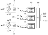
도 1 은 본 발명의 일 실시예에 따른 단상 고장에 대한 HVDC 시스템의 정류실패 제어 장치의 블럭 구성도이다.
도 2 는 본 발명의 일 실시예에 따른 3상 고장에 대한 HVDC 시스템의 정류실패 제어 장치의 블럭 구성도이다.
도 3 은 본 발명의 일 실시예에 따른 PCD를 이용하는 전류 제어기의 블럭 구성도이다. 1 is a block diagram of an apparatus for controlling rectification failure of an HVDC system for single-phase failure according to an embodiment of the present invention.
2 is a block diagram of an apparatus for controlling rectification failure of an HVDC system for a three-phase failure according to an embodiment of the present invention.
3 is a block diagram of a current controller using a PCD according to an embodiment of the present invention.
이하에서는 본 발명의 일 실시예에 따른 HVDC 시스템의 정류실패 제어 장치를 첨부된 도면들을 참조하여 상세하게 설명한다. 이러한 과정에서 도면에 도시된 선들의 두께나 구성요소의 크기 등은 설명의 명료성과 편의상 과장되게 도시되어 있을 수 있다. 또한 후술되는 용어들은 본 발명에서의 기능을 고려하여 정의된 용어들로서, 이는 이용자, 운용자의 의도 또는 관례에 따라 달라질 수 있다. 그러므로 이러한 용어들에 대한 정의는 본 명세서 전반에 걸친 내용을 토대로 내려져야할 것이다. Hereinafter, an apparatus for controlling rectification failure of an HVDC system according to an embodiment of the present invention will be described in detail with reference to the accompanying drawings. In this process, the thickness of the lines or the size of components shown in the drawings may be exaggerated for clarity and convenience of description. In addition, terms to be described later are terms defined in consideration of functions in the present invention, which may vary according to the intention or custom of users or operators. Therefore, definitions of these terms should be made based on the contents throughout the present specification.
일반적으로 HVDC(High Voltage Direct Current) 시스템에서 정류실패를 유발하는 AC 계통의 고장은 단상 고장과 3상 고장으로 구분된다. In general, AC system failures that cause rectification failure in HVDC (High Voltage Direct Current) systems are classified into single-phase failures and three-phase failures.
이에, 본 발명의 일 실시예에 따른 HVDC 시스템의 정류실패 제어 장치는 단상 고장을 판별하여 HVDC 시스템의 정류실패를 저감하기 위한 실시예 및 3상 고장을 판별하여 HVDC 시스템의 정류실패를 저감하기 위한 실시예로 각각 설명한다. Accordingly, the apparatus for controlling rectification failure of the HVDC system according to an embodiment of the present invention is an embodiment for reducing the rectification failure of the HVDC system by determining a single-phase failure, and for reducing the rectification failure of the HVDC system by determining a three-phase failure. Each will be described with examples.
특히, 본 발명의 일 실시예에 따른 HVDC 시스템의 정류실패 제어 장치는 단상 고장을 판별하기 위해 3상 전압과 3상 전류를 각각 스칼라적으로 합성하며, 상기한 바와 같이 각각 합성된 전압과 전류를 곱하여 전력 지령값을 생성한 후, 이 전력 지령값을 전류 지령값으로 변환하여 최종적으로 HVDC 시스템의 정류실패를 저감하기 위한 전류 기준값을 출력하는 것을 특징으로 한다. In particular, the apparatus for controlling rectification failure of the HVDC system according to an embodiment of the present invention synthesizes the three-phase voltage and the three-phase current in a scalar manner, respectively, in order to determine a single-phase failure, and the synthesized voltage and current are respectively synthesized as described above. After multiplying to generate a power command value, the power command value is converted into a current command value to finally output a current reference value for reducing rectification failure of the HVDC system.
또한, 본 발명의 일 실시예에 따른 HVDC 시스템의 정류실패 제어 장치는 3상 고장을 판별하기 위해 3상 전압과 3상 전류를 벡터적으로 합성하며, 상기한 바와 같이 각각 합성된 전압과 전류를 곱하여 전력 지령값을 생성한 후, 이 전력 지령값을 전류 지령값으로 변환하여 HVDC 시스템의 정류실패를 저감하기 위한 전류 기준값을 검출하는 것을 특징으로 한다.In addition, the device for controlling rectification failure of the HVDC system according to an embodiment of the present invention synthesizes a three-phase voltage and a three-phase current in a vector manner to determine a three-phase fault, and combines the synthesized voltage and current, respectively, as described above. After multiplying to generate a power command value, the power command value is converted into a current command value to detect a current reference value for reducing rectification failure of the HVDC system.
이하, 본 발명의 일 실시예에 따른 HVDC 시스템의 정류 실패 저감 장치를 도 1 내지 도 3 을 참조하여 상세하게 설명한다. Hereinafter, an apparatus for reducing rectification failure of an HVDC system according to an embodiment of the present invention will be described in detail with reference to FIGS. 1 to 3.
도 1 은 본 발명의 일 실시예에 따른 단상 고장에 대한 HVDC 시스템의 정류실패 제어 장치의 블럭 구성도이고, 도 2 는 본 발명의 일 실시예에 따른 3상 고장에 대한 HVDC 시스템의 정류실패 제어 장치의 블럭 구성도이며, 도 3 은 본 발명의 일 실시예에 따른 PCD를 이용한 전류 제어기의 블럭 구성도이다. 1 is a block diagram of an apparatus for controlling rectification failure of an HVDC system for a single-phase failure according to an embodiment of the present invention, and FIG. 2 is a block diagram of a rectification failure control of an HVDC system for a three-phase failure according to an embodiment of the present invention. It is a block diagram of the device, and FIG. 3 is a block diagram of a current controller using a PCD according to an embodiment of the present invention.
도 1 을 참조하면, 본 발명의 일 실시예에 따른 단상 고장에 대한 HVDC 시스템의 정류실패 제어 장치는 전압 스칼라 합성부(110), 전류 스칼라 합성부(120), 제1 곱셈기(130), 제1 전압 비교기(140), 제1 전류 비교기(150), 제1 지령값 비교기(160), 제1 판별부(170) 및 전류 제어기(10)(도 3 에 도시)를 포함한다. Referring to FIG. 1, the apparatus for controlling rectification failure of the HVDC system for single-phase failure according to an embodiment of the present invention includes a voltage
먼저, 전압 스칼라 합성부(110)는 3상 전압(ua(t),ub(t),uc(t))을 스칼라적으로 합성하여 절대값으로 생성하고, 이와 같이 생성된 합성 전압값(uO)을 제1 전압 비교기(140) 및 제1 곱셈기(130) 각각에 입력한다. First, the voltage scalar synthesis unit 110 generates an absolute value by synthesizing the three-phase voltage (u a (t), u b (t), u c (t)) in a scalar manner, and the resulting synthesized voltage The value u O is input to the
제1 전압 비교기(140)는 상기한 전압 스칼라 합성부(110)로부터 입력된 합성 전압값(u0)을 기 설정된 제1 합성 전압 기준값(KU0uM0)과 비교하고 비교 결과(1 or 0)를 제1 판별부(170)로 입력한다. The
여기서, 제1 합성 전압 기준값(KUOuMO)은 HVDC 시스템의 단상 고장을 예측할 수 있도록 사전에 설정된 전압 기준값이다. Here, the first combined voltage reference value K UO u MO is a voltage reference value set in advance to predict a single-phase failure of the HVDC system.
전류 스칼라 합성부(120)는 3상 전류(ian(t),ibn(t),icn(t))를 스칼라적으로 합성하여 절대값으로 생성하고, 이와 같이 생성된 합성 전류값(ion)을 제1 전류 비교기(150) 및 제1 곱셈기(130) 각각에 입력한다. The current scalar synthesis unit 120 generates an absolute value by synthesizing the three-phase current (i an (t), i bn (t), i cn (t)) in a scalar manner, and the resulting synthesized current value ( i on ) is input to each of the first
제1 전류 비교기(150)는 상기한 전류 스칼라 합성부(120)로부터 입력된 합성 전류값(ion)을 기 설정된 제1 합성 전류 기준값(KIOiMOn)과 비교하고 비교 결과(1 or 0)를 제1 판별부(170)로 입력한다. The first
여기서, 제1 합성 전류 기준값(KIOiMOn)은 HVDC 시스템의 단상 고장을 예측할 수 있도록 사전에 설정된 전류 기준값이다. Here, the first combined current reference value K IO i MOn is a current reference value set in advance to predict a single phase failure of the HVDC system.
제1 곱셈기(130)는 상기한 전압 스칼라 합성부(110)로부터 입력된 합성 전압값(uO)과 전류 스칼라 합성부(120)로부터 입력된 합성 전류값(ion)을 곱하여 전력 지령값(Pon)을 생성하고, 생성된 전력 지령값(Pon)을 제1 지령값 비교기(160)에 입력한다. 여기서, 제1 곱셈기(130)에 의해 생성된 전력 지령값(Pon)은 전류 제어기(10)의 PCD(Power Command Drive)(11)에 입력된다. The
제1 지령값 비교기(160)는 상기한 제1 곱셈기(130)로부터 입력된 전력 지령값(Pon)을 기 설정된 제1 전력지령 기준값(KpoPNOn)과 비교하고 비교 결과(1 or 0)를 제1 판별부(170)에 입력한다. The first
여기서, 제1 전력지령 기준값(KpoPNOn)은 HVDC 시스템의 단상 고장을 예측할 수 있도록 사전에 설정된 전력 기준값이다. Here, the first power command reference value K po P NOn is a power reference value set in advance to predict a single-phase failure of the HVDC system.
제1 판별부(170)는 제1 전압 비교기(140)와 제1 전류 비교기(150) 및 제1 지령값 비교기(160)의 비교 결과에 따라 단상 고장을 판별한다. The
이러한 제1 판별부(170)는 합성 전압값(uo)이 제1 합성 전압 기준값(KU0uM0) 이상이고, 합성 전류값(ion)이 제1 합성 전류 기준값(KIOiMOn) 이상이며, 전력 지령값(Pon)이 제1 전력지령 기준값(KpoPNOn) 이상이면 단상 고장으로 판별한다. 즉, 3상 전압(ua(t),ub(t),uc(t))을 스칼라적으로 합성한 합성 전압값(uo)과, 3상 전류(ian(t),ibn(t),icn(t))를 스칼라적으로 합성한 합성 전류값(ion) 및 합성 전압값(uo)과 합성 전류값(ion)을 곱하여 생성된 전력 지령값(Pon)이 각각의 기준값 이상인 경우에는, 3상 중 단상에 전압값이나 전류값이 과도하게 상승하여 단상 고장이 발생한 것으로 볼 수 있기 때문이다.The
반면에, 제1 판별부(170)는 합성 전압값(uo)이 제1 합성 전압 기준값(KUOuMO) 미만이거나, 합성 전류값(ion)이 제1 합성 전류 기준값(KIOiMOn) 미만이거나, 또는 전력 지령값(Pon)이 제1 전력지령 기준값(KpoPNOn) 미만이면 단상 고장이 발생되지 않은 것으로 판별한다. On the other hand, the
여기서, 단상 고장시 전류 제어기(10)는 제1 판별부(170)의 판별 결과에 따라 제1 곱셈기(130)로부터 전력 지령값(Pon)을 입력받고, 이 전력 지령값(Pon)을 이용하여 HVDC 시스템의 정류실패를 제어하기 위한 전류 기준값(Idcref)을 출력한다. 이에 대해서는 도 3 을 참조하여 후술한다. Here, in case of a single-phase failure, the
도 2 를 참조하면, 본 발명의 일 실시예에 따른 3상 고장에 대한 HVDC 시스템의 정류실패 제어 장치의 블럭 구성도이다.2, a block diagram of an apparatus for controlling rectification failure of an HVDC system for a three-phase failure according to an embodiment of the present invention is shown.
본 발명의 일 실시예에 따른 전압 벡터 합성부(210), 전류 벡터 합성부(220), 제2 곱셈기(230), 제2 전압 비교기(240), 제2 전류 비교기(250), 제2 지령값 비교기(260), 제2 판별부(270) 및 전류 제어기(10)(도 3 에 도시)를 포함한다.
먼저, 전압 벡터 합성부(210)는 3상 전압(ua(t),ub(t),uc(t))을 Park's Equation으로 변환한 후 벡터적으로 합성하여 절대값으로 생성하고, 이와 같이 생성된 합성 전압값(unth)을 제2 전압 비교기(240) 및 제2 곱셈기(230) 각각에 입력한다. First, the voltage
제2 전압 비교기(240)는 상기한 전압 벡터 합성부(210)로부터 입력된 합성 전압값(unth)을 기 설정된 제2 합성 전압 기준값(KUthuNth)과 비교하고 비교 결과(1 or 0)를 제2 판별부(270)에 입력한다. The
여기서, 제2 합성 전압 기준값(KUthuNth)은 HVDC 시스템의 3상 고장을 예측할 수 있도록 사전에 설정된 전압 기준값이다. Here, the second combined voltage reference value K Uth u Nth is a voltage reference value set in advance to predict a three-phase failure of the HVDC system.
전류 벡터 합성부(220)는 3상 전류(ian(t),ibn(t),icn(t))를 Park's Equation으로 변환한 후 벡터적으로 합성하여 절대값으로 생성하고, 이와 같이 생성된 합성 전류값(ithn)을 제2 전류 비교기(250) 및 제2 곱셈기(230) 각각에 입력한다. The current
제2 전류 비교기(250)는 상기한 전류 벡터 합성부(220)로부터 입력된 합성 전류값(ithn)을 기 설정된 제2 합성 전류 기준값(KIthiNthn)과 비교하고 비교 결과(1 or 0)를 제2 판별부(270)로 입력한다. The second
여기서, 제2 합성 전류 기준값(KIthiNthn)은 HVDC 시스템의 3상 고장을 예측할 수 있도록 사전에 설정된 전류 기준값이다. Here, the second combined current reference value K Ith i Nthn is a current reference value set in advance to predict a three-phase failure of the HVDC system.
제2 곱셈기(230)는 상기한 전압 벡터 합성부(210)로부터 입력된 합성 전압값(unth)과 전류 벡터 합성부(220)로부터 입력된 합성 전류값(ithn)을 곱하여 전력 지령값(ΔPnth)을 생성하고, 생성된 전력 지령값(ΔPnth)을 제2 지령값 비교기(260)에 입력한다. 여기서, 제2 곱셈기(230)에 의해 생성된 전력 지령값(ΔPnth)은 전류 제어기(10)의 PCD(11)에 입력된다. The
제2 지령값 비교기(260)는 상기한 제2 곱셈기(230)로부터 입력된 전력 지령값(ΔPnth)을 기 설정된 제2 전력지령 기준값(KpthΔPNth)과 비교하고 비교 결과(1 or 0)를 제2 판별부(270)에 입력한다. The second
여기서, 제2 전력지령 기준값(KpthΔPNth)은 HVDC 시스템의 3상 고장을 예측할 수 있도록 사전에 설정된 전력 기준값이다. Here, the second power command reference value K pth ΔP Nth is a power reference value set in advance to predict a three-phase failure of the HVDC system.
제2 판별부(270)는 제2 전압 비교기(240)와 제2 전류 비교기(250) 및 제2 지령값 비교기(260)의 비교 결과에 따라 3상 고장을 판별한다. The
이러한 제2 판별부(270)는 합성 전압값(unth)이 제2 합성 전압 기준값(KUthuNth) 이상이고, 합성 전류값(ithn)이 제2 합성 전류 기준값(KIthiNthn) 이상이며, 전력 지령값(ΔPnth)이 제2 전력지령 기준값(KpthΔPNth) 이상이면 3상 고장으로 판별한다. 즉, 3상 전압(ua(t),ub(t),uc(t))을 벡터적으로 합성한 합성 전압값(unth)과, 3상 전류(ian(t),ibn(t),icn(t))를 벡터적으로 합성한 합성 전류값(ithn) 및 합성 전압값(unth)과 합성 전류값(ithn)을 곱하여 생성된 전력 지령값(ΔPnth)이 각각의 기준값 이상인 경우에는, 3상 전체의 전압값이나 전류값이 과도하게 상승하여 그 벡터적 합성값이 과도하게 증가한 것으로 볼 수 있기 때문에 3상 고장이 발생한 것으로 판별할 수 있다. The
반면에, 제2 판별부(270)는 합성 전압값(unth)이 제2 합성 전압 기준값(KUthuNth) 미만이거나, 합성 전류값(ithn)이 제2 합성 전류 기준값(KIthiNthn) 미만이거나 전력 지령값(ΔPnth)이 제2 전력지령 기준값(KpthΔPNth) 미만이면 3상 고장이 발생되지 않은 것으로 판별한다. On the other hand, the
도 3 을 참조하면, 전류 제어기(10)는 단상 고장 또는 3상 고장에 따른 전력 지령값(Pon or ΔPnth) 중 어느 하나를 입력받고 입력된 전력 지령값(Pon or ΔPnth)을 이용하여 전류 기준값(Idcref)을 출력한다. Referring to FIG. 3, the
즉, 단상 고장시 전류 제어기(10)는 제1 판별부(170)의 판별 결과에 따라 제1 곱셈기(130)로부터 전력 지령값(Pon)을 입력받고, 이 전력 지령값(Pon)을 이용하여 HVDC 시스템의 정류실패를 제어하기 위한 전류 기준값(Idcref)을 출력한다. That is, in case of a single-phase failure, the
또는 3상 고장시 전류 제어기(10)는 제2 판별부(270)의 판별 결과에 따라 제2 곱셈기(230)로부터 전력 지령값(ΔPnth)을 입력받고, 전력 지령값(ΔPnth)을 이용하여 HVDC 시스템의 정류실패를 제어하기 위한 전류 기준값(Idcref)을 출력한다. Alternatively, in the case of a three-phase failure, the
이를 위해, 전류 제어기(10)는 도 3 에 도시된 바와 같이 PCD(Power Command Drive)(11), 전력 제어기(12), VDCOL(Voltage Dependant Current Order Limit) 모듈(13) 및 선택부(14)를 포함한다. To this end, the
PCD(11)는 전력 지령값(Pon or ΔPnth)을 전류 지령값(Iordl)으로 변환하여 선택부(14)에 입력한다. The
전력 제어기(12)는 HVDC 시스템의 전력을 기반으로 전류 지령값(Iord2)을 생성한다.The
VDCOL(Voltage Dependant Current Order Limit) 모듈(13)은 HVDC 시스템의 전압에 설정된 전류 지령값을 검출하는 것으로서, 계통의 전압이 강하하는 경우 기 설정된 룩업 테이블을 바탕으로 해당 전압에 대해 설정된 전류 지령값(Iord3)을 검출하고 이 전류 지령값(Iord3)을 선택부(14)에 입력한다. The VDCOL (Voltage Dependant Current Order Limit)
참고로, 전력 제어기(12) 및 VDCOL 모듈(13)은 당업자가 용이하게 실시할 수 있으므로 여기서는 그 상세한 설명을 생략한다. For reference, since the
선택부(14)는 상기한 PCD(11)로부터 입력되는 전류 지령값(Iordl)을 상기한 전류 기준값(Idcref)으로 선택할 수 있으며, 이외에도 PCD(11)로부터 입력되는 전류 지령값(Iordl)과, 전력 제어기(12)로부터 입력된 전류 지령값(Iord2) 및 VDCOL 모듈(13)로부터 입력된 전류 지령값(Iord3) 중 최소값을 전류 기준값(Idcref)으로 선택하여 출력할 수 있다. Selecting
이와 같은 본 실시예는 AC 전압을 기반으로 단상 및 3상에서의 정류실패를 사전에 예측하고 예측 결과를 토대로 정류실패를 사전에 제어한다.In this embodiment, the rectification failure in single and three phases is predicted in advance based on the AC voltage, and the rectification failure is controlled in advance based on the prediction result.
또한 본 실시예는 HVDC 시스템에 고장이 발생하더라도 고장 회복속도가 빠르고 추가적인 정류실패를 예방할 수 있도록 한다. In addition, the present embodiment makes it possible to prevent an additional rectification failure with a fast failure recovery speed even if a failure occurs in the HVDC system.
본 발명은 도면에 도시된 실시예를 참고로 하여 설명되었으나, 이는 예시적인 것에 불과하며 당해 기술이 속하는 기술분야에서 통상의 지식을 가진 자라면 이로부터 다양한 변형 및 균등한 타 실시예가 가능하다는 점을 이해할 것이다. 따라서, 본 발명의 진정한 기술적 보호범위는 아래의 특허청구범위에 의하여 정해져야할 것이다.The present invention has been described with reference to the embodiments shown in the drawings, but these are only exemplary, and those of ordinary skill in the art to which the present technology pertains, various modifications and other equivalent embodiments are possible. I will understand. Therefore, the true technical protection scope of the present invention should be determined by the following claims.
10: 전류 제어기
11: PCD
12: 전력 제어기
13: VCDOL 모듈
14: 선택부
110: 전압 스칼라 합성부
120: 전류 스칼라 합성부
130: 제1 곱셈기
140: 제1 전압 비교기
150: 제1 전류 비교기
160: 제1 지령값 비교기
170: 제1 판별부
210: 전압 벡터 합성부
220: 전류 벡터 합성부
230: 제2 곱셈기
240: 제2 전압 비교기
250: 제2 전류 비교기
260: 제2 지령값 비교기
270: 제2 판별부 10: current controller
11: PCD
12: power controller
13: VCDOL module
14: selection
110: voltage scalar synthesis unit
120: current scalar synthesis unit
130: first multiplier
140: first voltage comparator
150: first current comparator
160: first command value comparator
170: first discrimination unit
210: voltage vector synthesis unit
220: current vector synthesis unit
230: second multiplier
240: second voltage comparator
250: second current comparator
260: second command value comparator
270: second determination unit
Claims (8)
3상 전류를 스칼라적으로 합성하여 합성 전류값을 생성하는 전류 스칼라 합성부;
상기 합성 전압값과 상기 합성 전류값을 곱하여 전력 지령값을 생성하는 제1 곱셈기;
상기 합성 전압값과 기 설정된 제1 합성 전압 기준값을 비교하는 제1 전압 비교기;
상기 합성 전류값과 기 설정된 제1 합성 전류 기준값을 비교하는 제1 전류 비교기;
상기 전력 지령값을 기 설정된 제1 전력지령 기준값과 비교하는 제1 지령값 비교기;
상기 제1 전압 비교기와 상기 제1 전류 비교기 및 상기 제1 지령값 비교기의 비교 결과에 따라 HVDC 시스템의 단상 고장을 판별하는 제1 판별부; 및
상기 제1 판별부의 판별 결과 단상 고장으로 판별되면, 상기 전력 지령값을 전류 지령값으로 변환하여 상기 전류 지령값을 상기 HVDC 시스템의 정류실패를 제어하기 위한 전류 기준값으로 출력하는 전류 제어기를 포함하는 HVDC 시스템의 정류실패 제어 장치. A voltage scalar synthesizer for generating a synthesized voltage value by synthesizing the three-phase voltage scalar;
A current scalar synthesizer for generating a synthesized current value by synthesizing the three-phase current scalar;
A first multiplier for generating a power command value by multiplying the synthesized voltage value and the synthesized current value;
A first voltage comparator for comparing the synthesized voltage value and a preset first synthesized voltage reference value;
A first current comparator for comparing the synthesized current value with a preset first synthesized current reference value;
A first command value comparator for comparing the power command value with a preset first power command reference value;
A first determination unit for determining a single-phase failure of the HVDC system according to a comparison result of the first voltage comparator, the first current comparator, and the first command value comparator; And
HVDC including a current controller that converts the power command value into a current command value and outputs the current command value as a current reference value for controlling rectification failure of the HVDC system when it is determined as a single-phase failure as a result of the determination by the first determination unit A device for controlling commutation failure of the system.
상기 전력 지령값을 상기 전류 지령값으로 변환하는 PCD(Power Command Drive); 및
상기 전류 지령값을 상기 전류 기준값으로 선택하는 선택부를 포함하는 것을 특징으로 하는 HVDC 시스템의 정류실패 제어 장치. The method of claim 1, wherein the current controller
A PCD (Power Command Drive) for converting the power command value into the current command value; And
And a selection unit for selecting the current command value as the current reference value.
상기 HVDC 시스템의 전력을 기반으로 전류 지령값을 생성하는 전력 제어기, 및 상기 HVDC 시스템의 전압에 설정된 전류 지령값을 검출하는 VDCOL(Voltage Dependant Current Order Limit) 모듈을 더 포함하되,
상기 선택부는 상기 PCD, 상기 전력 제어기 및 상기 VDCOL 모듈 각각으로부터 입력된 상기 전류 지령값 중 최소값을 상기 전류 기준값으로 선택하는 것을 특징으로 하는 HVDC 시스템의 정류실패 제어 장치. The method of claim 3, wherein the current controller
Further comprising a power controller that generates a current command value based on the power of the HVDC system, and a voltage dependent current order limit (VDCOL) module that detects a current command value set in the voltage of the HVDC system,
The selection unit selects a minimum value of the current command values input from each of the PCD, the power controller, and the VDCOL module as the current reference value.
3상 전류를 벡터적으로 합성하여 합성 전류값을 생성하는 전류 벡터 합성부;
상기 합성 전압값과 상기 합성 전류값에 근거하여 전력 지령값을 생성하는 제2 곱셈기;
상기 합성 전압값과 기 설정된 제2 합성 전압 기준값을 비교하는 제2 전압 비교기;
상기 합성 전류값과 기 설정된 제2 합성 전류 기준값을 비교하는 제2 전류 비교기;
상기 전력 지령값을 기 설정된 제2 전력지령 기준값과 비교하는 제2 지령값 비교기;
상기 제2 전압 비교기와 상기 제2 전류 비교기 및 상기 제2 지령값 비교기의 비교 결과에 따라 HVDC 시스템의 3상 고장을 판별하는 제2 판별부; 및
상기 제2 판별부의 판별 결과 3상 고장으로 판별되면, 상기 전력 지령값을 전류 지령값으로 변환하여 상기 전류 지령값을 상기 HVDC 시스템의 정류실패를 제어하기 위한 전류 기준값으로 출력하는 전류 제어기를 포함하는 HVDC 시스템의 정류실패 제어 장치. A voltage vector synthesizer for generating a synthesized voltage value by vector synthesizing the three-phase voltages;
A current vector synthesis unit for generating a synthesized current value by vector synthesizing the three-phase current;
A second multiplier for generating a power command value based on the synthesized voltage value and the synthesized current value;
A second voltage comparator for comparing the synthesized voltage value and a preset second synthesized voltage reference value;
A second current comparator for comparing the synthesized current value and a preset second synthesized current reference value;
A second command value comparator for comparing the power command value with a preset second power command reference value;
A second determination unit for determining a three-phase fault of the HVDC system according to a comparison result of the second voltage comparator, the second current comparator, and the second command value comparator; And
A current controller converting the power command value into a current command value and outputting the current command value as a current reference value for controlling a rectification failure of the HVDC system when it is determined as a 3-phase failure as a result of the determination by the second determination unit. Control device for commutation failure of HVDC system.
상기 전력 지령값을 상기 전류 지령값으로 변환하는 PCD(Power Command Drive); 및
상기 전류 지령값을 상기 전류 기준값으로 선택하는 선택부를 포함하는 것을 특징으로 하는 HVDC 시스템의 정류실패 제어 장치. The method of claim 5, wherein the current controller
A PCD (Power Command Drive) for converting the power command value into the current command value; And
And a selection unit for selecting the current command value as the current reference value.
상기 HVDC 시스템의 전력을 기반으로 전류 지령값을 생성하는 전력 제어기, 및 상기 HVDC 시스템의 전압에 설정된 전류 지령값을 검출하는 VDCOL(Voltage Dependant Current Order Limit) 모듈을 더 포함하되,
상기 선택부는 상기 PCD, 상기 전력 제어기 및 상기 VDCOL 모듈 각각으로부터 입력된 상기 전류 지령값 중 최소값을 상기 전류 기준값으로 선택하는 것을 특징으로 하는 HVDC 시스템의 정류실패 제어 장치. The method of claim 7, wherein the current controller
Further comprising a power controller that generates a current command value based on the power of the HVDC system, and a voltage dependent current order limit (VDCOL) module that detects a current command value set in the voltage of the HVDC system,
The selection unit selects a minimum value of the current command values input from each of the PCD, the power controller, and the VDCOL module as the current reference value.
Priority Applications (1)
| Application Number | Priority Date | Filing Date | Title |
|---|---|---|---|
| KR1020140123912A KR102224966B1 (en) | 2014-09-17 | 2014-09-17 | Apparatus controlling commutation failure of hvdc system |
Applications Claiming Priority (1)
| Application Number | Priority Date | Filing Date | Title |
|---|---|---|---|
| KR1020140123912A KR102224966B1 (en) | 2014-09-17 | 2014-09-17 | Apparatus controlling commutation failure of hvdc system |
Publications (2)
| Publication Number | Publication Date |
|---|---|
| KR20160033362A KR20160033362A (en) | 2016-03-28 |
| KR102224966B1 true KR102224966B1 (en) | 2021-03-11 |
Family
ID=57007515
Family Applications (1)
| Application Number | Title | Priority Date | Filing Date |
|---|---|---|---|
| KR1020140123912A Active KR102224966B1 (en) | 2014-09-17 | 2014-09-17 | Apparatus controlling commutation failure of hvdc system |
Country Status (1)
| Country | Link |
|---|---|
| KR (1) | KR102224966B1 (en) |
Families Citing this family (6)
| Publication number | Priority date | Publication date | Assignee | Title |
|---|---|---|---|---|
| CN108493977B (en) * | 2018-03-15 | 2021-03-16 | 四川大学 | A Transient Reactive Power Coordinated Control Method for Series Hybrid DC Transmission System |
| CN112567620B (en) * | 2018-08-30 | 2024-03-01 | 日立安斯泰莫株式会社 | Inverter device |
| CN110968073B (en) * | 2019-11-22 | 2021-04-02 | 四川大学 | Double-layer tracing identification method for commutation failure reasons of HVDC system |
| CN113708401B (en) * | 2021-08-24 | 2024-07-30 | 国网河南省电力公司电力科学研究院 | Multi-input DC commutation failure prevention control method and system based on connection channel current detection |
| CN113791294B (en) * | 2021-09-07 | 2023-10-31 | 国网安徽省电力有限公司 | An edge-cloud collaborative commutation failure source tracing method for UHV DC transmission systems |
| CN119921373B (en) * | 2025-01-14 | 2025-12-05 | 清华大学 | Commutation Failure Suppression Method and Apparatus Based on Static Safety Boundary and Predictive Control |
Citations (1)
| Publication number | Priority date | Publication date | Assignee | Title |
|---|---|---|---|---|
| KR101096146B1 (en) | 2011-01-20 | 2011-12-19 | 한국전력공사 | HCDC controller and HCDC system including the same |
Family Cites Families (3)
| Publication number | Priority date | Publication date | Assignee | Title |
|---|---|---|---|---|
| KR20120106461A (en) * | 2011-03-18 | 2012-09-26 | 엘에스산전 주식회사 | Apparatus for preventing commutation failure of hvdc system |
| KR20130046113A (en) * | 2011-10-27 | 2013-05-07 | 한국전력공사 | HBCD controller |
| KR101986550B1 (en) * | 2012-09-18 | 2019-06-07 | 한국전력공사 | Apparatus for Controlling Extinction Angle for Preventing Commutation Failure of HVDC System |
-
2014
- 2014-09-17 KR KR1020140123912A patent/KR102224966B1/en active Active
Patent Citations (1)
| Publication number | Priority date | Publication date | Assignee | Title |
|---|---|---|---|---|
| KR101096146B1 (en) | 2011-01-20 | 2011-12-19 | 한국전력공사 | HCDC controller and HCDC system including the same |
Also Published As
| Publication number | Publication date |
|---|---|
| KR20160033362A (en) | 2016-03-28 |
Similar Documents
| Publication | Publication Date | Title |
|---|---|---|
| KR102224966B1 (en) | Apparatus controlling commutation failure of hvdc system | |
| CA2765464C (en) | Controlling an inverter device for supporting an ac system | |
| JP7008892B1 (en) | Control device and power converter | |
| JP5589141B2 (en) | Operation control device for photovoltaic power generation system | |
| KR101806595B1 (en) | Apparatus for controlling inverter | |
| KR101553765B1 (en) | Method and system for preventing commutation failure in high-voltage direct current system | |
| JP6583922B2 (en) | Power converter | |
| JP5134691B2 (en) | Self-excited reactive power compensator | |
| JP4664699B2 (en) | Parallel operation controller for power converter | |
| WO2016132970A1 (en) | Control device of power converter | |
| KR20140039389A (en) | Apparatus and method for controlling diminishing power fluctuation of small wind turbine system | |
| JP2012231606A (en) | System interconnection power conversion device | |
| JP5123673B2 (en) | Power converter | |
| JPH09163752A (en) | PWM control self-excited rectifier | |
| JP2018093558A (en) | Electric power conversion system | |
| JP6258806B2 (en) | Power converter for grid connection | |
| KR102638961B1 (en) | Inverter apparatus capable of high speed operation mode switching and high speed start-up and control method thereof | |
| WO2018020666A1 (en) | Power conversion device and control method therefor | |
| JP2014023310A (en) | Converter system control method and control device | |
| JP2008312370A (en) | Reactive power compensating device and control method therefor | |
| JP7155076B2 (en) | Controller and power conversion system | |
| KR101936564B1 (en) | Apparatus for controlling multilevel inverter | |
| KR20000020272A (en) | Potential source excitation system using space voltage vector method | |
| EP3806262A1 (en) | Control device and power conversion device | |
| JP4258228B2 (en) | Control method and control apparatus for power conversion device for fuel cell |
Legal Events
| Date | Code | Title | Description |
|---|---|---|---|
| PA0109 | Patent application |
St.27 status event code: A-0-1-A10-A12-nap-PA0109 |
|
| R18-X000 | Changes to party contact information recorded |
St.27 status event code: A-3-3-R10-R18-oth-X000 |
|
| PG1501 | Laying open of application |
St.27 status event code: A-1-1-Q10-Q12-nap-PG1501 |
|
| P22-X000 | Classification modified |
St.27 status event code: A-2-2-P10-P22-nap-X000 |
|
| P22-X000 | Classification modified |
St.27 status event code: A-2-2-P10-P22-nap-X000 |
|
| R18-X000 | Changes to party contact information recorded |
St.27 status event code: A-3-3-R10-R18-oth-X000 |
|
| R18-X000 | Changes to party contact information recorded |
St.27 status event code: A-3-3-R10-R18-oth-X000 |
|
| A201 | Request for examination | ||
| PA0201 | Request for examination |
St.27 status event code: A-1-2-D10-D11-exm-PA0201 |
|
| R18-X000 | Changes to party contact information recorded |
St.27 status event code: A-3-3-R10-R18-oth-X000 |
|
| D13-X000 | Search requested |
St.27 status event code: A-1-2-D10-D13-srh-X000 |
|
| D14-X000 | Search report completed |
St.27 status event code: A-1-2-D10-D14-srh-X000 |
|
| E902 | Notification of reason for refusal | ||
| PE0902 | Notice of grounds for rejection |
St.27 status event code: A-1-2-D10-D21-exm-PE0902 |
|
| P11-X000 | Amendment of application requested |
St.27 status event code: A-2-2-P10-P11-nap-X000 |
|
| P13-X000 | Application amended |
St.27 status event code: A-2-2-P10-P13-nap-X000 |
|
| E701 | Decision to grant or registration of patent right | ||
| PE0701 | Decision of registration |
St.27 status event code: A-1-2-D10-D22-exm-PE0701 |
|
| GRNT | Written decision to grant | ||
| PR0701 | Registration of establishment |
St.27 status event code: A-2-4-F10-F11-exm-PR0701 |
|
| PR1002 | Payment of registration fee |
St.27 status event code: A-2-2-U10-U11-oth-PR1002 Fee payment year number: 1 |
|
| PG1601 | Publication of registration |
St.27 status event code: A-4-4-Q10-Q13-nap-PG1601 |
|
| PR1001 | Payment of annual fee |
St.27 status event code: A-4-4-U10-U11-oth-PR1001 Fee payment year number: 4 |
|
| PR1001 | Payment of annual fee |
St.27 status event code: A-4-4-U10-U11-oth-PR1001 Fee payment year number: 5 |
|
| U11 | Full renewal or maintenance fee paid |
Free format text: ST27 STATUS EVENT CODE: A-4-4-U10-U11-OTH-PR1001 (AS PROVIDED BY THE NATIONAL OFFICE) Year of fee payment: 5 |