KR101741227B1 - Auto stereoscopic image display device - Google Patents
Auto stereoscopic image display device Download PDFInfo
- Publication number
- KR101741227B1 KR101741227B1 KR1020160022478A KR20160022478A KR101741227B1 KR 101741227 B1 KR101741227 B1 KR 101741227B1 KR 1020160022478 A KR1020160022478 A KR 1020160022478A KR 20160022478 A KR20160022478 A KR 20160022478A KR 101741227 B1 KR101741227 B1 KR 101741227B1
- Authority
- KR
- South Korea
- Prior art keywords
- image
- stereoscopic image
- depth
- lens
- stereoscopic
- Prior art date
- Legal status (The legal status is an assumption and is not a legal conclusion. Google has not performed a legal analysis and makes no representation as to the accuracy of the status listed.)
- Active
Links
Images


Classifications
-
- H04N13/0459—
-
- B29C67/0085—
-
- B—PERFORMING OPERATIONS; TRANSPORTING
- B33—ADDITIVE MANUFACTURING TECHNOLOGY
- B33Y—ADDITIVE MANUFACTURING, i.e. MANUFACTURING OF THREE-DIMENSIONAL [3D] OBJECTS BY ADDITIVE DEPOSITION, ADDITIVE AGGLOMERATION OR ADDITIVE LAYERING, e.g. BY 3D PRINTING, STEREOLITHOGRAPHY OR SELECTIVE LASER SINTERING
- B33Y30/00—Apparatus for additive manufacturing; Details thereof or accessories therefor
-
- G02B27/2214—
-
- G—PHYSICS
- G02—OPTICS
- G02B—OPTICAL ELEMENTS, SYSTEMS OR APPARATUS
- G02B3/00—Simple or compound lenses
- G02B3/02—Simple or compound lenses with non-spherical faces
- G02B3/08—Simple or compound lenses with non-spherical faces with discontinuous faces, e.g. Fresnel lens
-
- G—PHYSICS
- G02—OPTICS
- G02B—OPTICAL ELEMENTS, SYSTEMS OR APPARATUS
- G02B6/00—Light guides; Structural details of arrangements comprising light guides and other optical elements, e.g. couplings
- G02B6/0001—Light guides; Structural details of arrangements comprising light guides and other optical elements, e.g. couplings specially adapted for lighting devices or systems
- G02B6/0011—Light guides; Structural details of arrangements comprising light guides and other optical elements, e.g. couplings specially adapted for lighting devices or systems the light guides being planar or of plate-like form
- G02B6/0013—Means for improving the coupling-in of light from the light source into the light guide
- G02B6/0023—Means for improving the coupling-in of light from the light source into the light guide provided by one optical element, or plurality thereof, placed between the light guide and the light source, or around the light source
- G02B6/003—Lens or lenticular sheet or layer
Landscapes
- Physics & Mathematics (AREA)
- General Physics & Mathematics (AREA)
- Optics & Photonics (AREA)
- Chemical & Material Sciences (AREA)
- Engineering & Computer Science (AREA)
- Manufacturing & Machinery (AREA)
- Materials Engineering (AREA)
- Testing, Inspecting, Measuring Of Stereoscopic Televisions And Televisions (AREA)
- Stereoscopic And Panoramic Photography (AREA)
Abstract
본 발명은 입체 영상 표시 장치를 공개한다. 본 발명의 바람직한 실시예는, 입체 영상 표시 장치로 출력할 객체에 대한 RGB 영상 및 깊이 영상을 이용하여 깊이 차등 영상을 생성하고, 깊이 차등 영상을 렌즈 어레이에 투영시켜 깊이 정보가 반영된 입체 영상 신호를 생성한 후, 입체 영상 신호를 투명 LCD 패널에 디스플레이하고, 디스플레이된 영상을, 입체 영상을 생성할 때 사용된 렌즈 어레이와 동일한 렌즈 어레이를 통과시킴으로써, 각 픽셀마다 깊이값이 반영된 입체 영상, 즉, 영상에 포함된 각 영역마다 실제 깊이값에 대응되도록 초점거리가 서로 다른 입체 영상을 출력할 수 있다.The present invention discloses a stereoscopic image display device. In a preferred embodiment of the present invention, a depth difference image is generated using an RGB image and a depth image for an object to be output to a stereoscopic image display device, and a depth difference image is projected on a lens array to generate a stereoscopic image signal The stereoscopic image signal is displayed on the transparent LCD panel and the displayed image is passed through the same lens array as the lens array used for generating the stereoscopic image, It is possible to output a stereoscopic image having a different focal distance so as to correspond to an actual depth value for each region included in the image.
Description
본 발명은 입체 영상 표시 장치에 관한 것으로서, 보다 구체적으로는 무안경 입체 영상 표시 장치에 관한 것이다.
BACKGROUND OF THE
일반적으로 3차원을 표현하는 입체화상은 두 눈을 통한 스테레오 시각의 원리에 의하여 이루어지게 되는데, 두 눈의 시차 즉, 두 눈이 약 65mm 정도 떨어져서 존재하기 때문에, 두 눈의 위치의 차이로 왼쪽과 오른쪽 눈은 서로 약간 다른 영상을 보게 된다. 이와 같이, 두 눈의 위치 차이에 의한 영상의 차이점을 양안 시차(binocular disparity)라고 한다. 그리고, 3차원 입체 표시 장치는 이러한 양안 시차를 이용하여 왼쪽 눈은 왼쪽 눈에 대한 영상만 보게 하고 오른쪽 눈은 오른쪽 눈 영상만을 볼 수 있게 한다.In general, stereoscopic images representing three-dimensional images are made by the principle of stereoscopic vision through two eyes. Since the time difference of the two eyes, that is, the two eyes, is about 65 mm apart, The right eye sees a slightly different image. Thus, the difference in the image due to the positional difference between the two eyes is referred to as binocular disparity. The three-dimensional stereoscopic display apparatus uses the binocular parallax to allow the left eye to see only the left eye image, and the right eye to see only the right eye image.
즉, 좌/우의 눈은 각각 서로 다른 2차원 화상을 보게 되고, 이 두 화상이 망막을 통해 뇌로 전달되면 뇌는 이를 정확히 서로 융합하여 본래 3차원 영상의 깊이감과 실제감을 재생하는 것이다. 이러한 능력을 통상 스테레오그라피(stereography)라 하며, 이를 표시 장치로 응용한 장치를 입체 표시 장치라 한다.In other words, the left and right eyes see different two-dimensional images, and when these two images are transmitted to the brain through the retina, the brain fuses them exactly to reproduce the depth sense and real feeling of the original three-dimensional image. This capability is generally referred to as stereography, and a device using the same as a display device is referred to as a stereoscopic display device.
종래의 3차원 입체 영상 표시 장치는, 사용자가 편광 안경 또는 셔터글래스 방식의 안경을 착용하고, 3차원 입체 영상 표시장치가 좌안용 영상과 우안용 영상을 동시에 겹쳐서 표시하거나 또는 매우 빠른 시간 주기로 교번적으로 표시함으로써 사용자로 하여금 입체감을 느끼게 하는 방식이었다.A conventional three-dimensional image display device is a stereoscopic image display device in which a user wears polarized glasses or glasses of shutter glass type and displays a three-dimensional image by superimposing a left eye image and a right eye image at the same time, So that the user can feel the stereoscopic effect.
그런데, 양안시차를 이용하여 입체 영상을 시청하면, 두 영상의 시차와 눈의 초점기능의 부조화로 인해 어지러움과 눈의 피로감이 발생한다. 따라서, 최근에는 스테레오그라피의 문제점을 해결할 수 있는 집적 영상(Integral Imaging) 방식을 적용하는 연구들이 많이 수행되고 있다.However, when stereoscopic images are viewed using the binocular parallax, dizziness and eye fatigue are caused by the parallax of the two images and the mismatch of the focus functions of the eyes. Therefore, in recent years, many researches have been conducted to apply an integral imaging method which can solve the problem of stereo image.
집적 영상(integral imaging) 방식은 1908년 리프만(Lippmann)에 의해 처음 제안된 방식이다. 집적 영상 방식은 홀로그램과 같은 이미지로 영상을 집적하여 인식하는 것으로, 안경을 이용하지 않고 복수개의 단일 렌즈로 구성된 렌즈 어레이를 이용하여 2차원 전체 요소 영상으로부터 특정 깊이를 갖는 3차원 영상을 일정한 체적 내에서 표현한다. 즉, 시청자는 일정한 체적 내에서 형성된 3차원 영상을 보면서 실제 3차원 물체를 보는 것과 같이 느낄 수 있다.The integral imaging method was first proposed by Lippmann in 1908. The integrated image method is a method of collecting images by using an image such as a hologram and recognizing the three-dimensional image having a specific depth from a two-dimensional whole element image using a lens array composed of a plurality of single lenses without using glasses. . That is, a viewer can feel as if he or she is viewing a real three-dimensional object while viewing a three-dimensional image formed within a certain volume.
이러한 집적 영상 방식은 입체 영상을 시청하는데 안경이나 기타 도구가 필요하지 않으며, 시청자가 입체 영상을 시청할 때 눈의 피로감이 발생하지 않으며 연속적인 영상 재현이 가능하다.Such an integrated image method does not require glasses or other tools for viewing a stereoscopic image, and it is possible to reproduce a continuous image without causing eye fatigue when a viewer views the stereoscopic image.
그러나, 이러한 집적 영상 방식의 입체 영상의 경우에, 렌즈 어레이를 통과하여 카메라에 픽업되는 영상은 특정 깊이에서 촬영된 영상이므로 서로 다른 깊이를 갖는 객체를 정확하게 표현할 수 없는 한계가 있다. 즉, 공간상에 카메라로부터의 거리가 서로 다른 객체들을 촬영한 후, 촬영된 영상을 집적 영상 방식의 입체 영상으로 표시하는 경우에, 각 객체는 입체적으로 보일 수 있으나, 각 입체는 동일한 특정 평면에서 촬영되었으므로 동일한 초점 거리를 갖게 되어, 각 객체간 위치의 전후 관계, 즉, 서로 다른 객체의 깊이값을 입체적으로 표시할 수 없는 한계가 있다.
However, in the case of such an integrated image stereoscopic image, an image picked up by a camera through a lens array is an image photographed at a specific depth, and thus there is a limit in that an object having different depths can not be accurately represented. That is, when objects photographed with different distances from the camera on the space are photographed and the photographed images are displayed as a stereoscopic image of the integrated image system, each object can be seen in three dimensions, but each three- There is a limitation in that it is impossible to three-dimensionally display the relationship between the positions of the objects, that is, depth values of different objects.
본 발명이 해결하고자 하는 과제는, 입체 영상에서 표시될 객체들이 서로 다른 깊이값을 갖는 경우에, 깊이 정보를 반영하여 각 객체의 초점 거리가 깊이값에 대응되도록 하는 입체 영상 신호를 생성하여 입체 영상 표시 장치에서 표시함으로써, 입체 영상에서 표시되는 객체들이 실제 깊이값에 대응되는 초점거리를 갖도록 표시하는 입체 영상 표시 장치를 제공하는 것이다.
SUMMARY OF THE INVENTION It is an object of the present invention to provide a stereoscopic image display method and a stereoscopic image display method in which, when objects to be displayed in a stereoscopic image have different depth values, a stereoscopic image signal is generated in which the focal distance of each object corresponds to a depth value, And displaying the objects on the display device so that the objects displayed in the stereoscopic image have a focal distance corresponding to an actual depth value.
상술한 과제를 해결하기 위한 본 발명의 바람직한 실시예에 따른 입체 영상 표시 장치는, 빛을 발생시키는 광원; 상기 광원에서 발생된 빛이 제 1 변환 렌즈 전체 영역에 균일하게 조사되도록 하는 집광 렌즈; 상기 집광렌즈를 통과한 빛을 평행광으로 변환하는 상기 제 1 변환 렌즈; 집적 영상(integral imaging) 신호로 구현되는 입체 영상 신호를 출력하는 영상 신호 출력부; 상기 제 1 변환 렌즈를 통과한 빛을 광원으로 하여, 상기 입체 영상 신호를 디스플레이하는 투명 LCD 패널; 상기 투명 LCD 패널에서 디스플레이되는 영상을 렌즈 어레이로 집광시키는 제 2 변환 렌즈; 상기 제 2 변환 렌즈를 통과한 영상을 입체 영상으로 표시하는 상기 렌즈 어레이; 및 상기 렌즈 어레이로부터 출력된 입체 영상을 확산시키는 투사 렌즈를 포함한다.According to an aspect of the present invention, there is provided a stereoscopic image display device including: a light source for generating light; A condensing lens for uniformly irradiating light generated from the light source on the entire area of the first conversion lens; A first conversion lens for converting light passing through the condenser lens into parallel light; A video signal output unit for outputting a stereoscopic image signal embodied as an integral imaging signal; A transparent LCD panel for displaying the stereoscopic image signal using light having passed through the first conversion lens as a light source; A second conversion lens for condensing the image displayed on the transparent LCD panel into a lens array; A lens array for displaying an image having passed through the second conversion lens as a stereoscopic image; And a projection lens for diffusing the stereoscopic image output from the lens array.
또한, 상기 렌즈 어레이는 상기 입체 영상 신호를 생성할 때 이용된 렌즈 어레이와 동일하거나, 동일한 파라미터를 갖는 것이 바람직하다.It is preferable that the lens array has the same or the same parameter as the lens array used when the stereoscopic image signal is generated.
또한, 상기 렌즈 어레이를 통과한 입체 영상은, 입체 영상으로 표시되는 객체의 형상에 따라서 초점 거리가 서로 다른 영역들이 존재할 수 있다.Also, in the stereoscopic image passed through the lens array, there may exist regions having different focal distances depending on the shape of the object displayed as the stereoscopic image.
또한, 상기 입체 영상 신호는, 가상의 렌즈 어레이로부터 일정한 간격으로 복수의 가상의 물체면을 설정하고, 상기 깊이 영상의 각 픽셀에 대해서 픽셀값에 따라서 복수의 가상의 물체면 중 어느 하나를 선택하고, 선택된 물체면의 상기 깊이 영상의 각 픽셀에 대응되는 위치에, 상기 RGB 영상의 대응되는 위치의 픽셀값을 설정함으로써, 깊이 차등 영상을 생성하고, 상기 깊이 차등 영상을 상기 가상의 렌즈 어레이에 투영한 영상을 이용하여 생성될 수 있다.The stereoscopic image signal may be obtained by setting a plurality of virtual object planes at regular intervals from a virtual lens array and selecting one of a plurality of virtual object planes for each pixel of the depth image according to a pixel value , Generating a depth difference image by setting a pixel value at a corresponding position of the RGB image at a position corresponding to each pixel of the depth image of the selected object plane and projecting the depth difference image to the virtual lens array Can be generated using one image.
또한, 입체 영상 표시 장치는, 상기 입체 영상 신호를 생성하여 영상 신호 출력부로 제공하는 영상신호 생성부를 더 포함하고, 상기 영상신호 생성부는 입체 영상으로 표시할 객체의 RGB 영상 및 상기 객체의 깊이 정보를 포함하는 깊이 영상을 이용하여 상기 입체 영상 신호를 생성할 수 있다.The stereoscopic image display apparatus may further include an image signal generation unit for generating the stereoscopic image signal and providing the stereoscopic image signal to the image signal output unit. The image signal generation unit may generate an RGB image of the object to be displayed as a stereoscopic image, The depth image including the depth image may be used to generate the stereoscopic image signal.
또한, 상기 영상신호 생성부는, 가상의 렌즈 어레이로부터 일정한 간격으로 복수의 가상의 물체면을 설정하고, 상기 깊이 영상의 각 픽셀에 대해서 픽셀값에 따라서 복수의 가상의 물체면 중 어느 하나를 선택하고, 선택된 물체면의 상기 깊이 영상의 각 픽셀에 대응되는 위치에, 상기 RGB 영상의 대응되는 위치의 픽셀값을 설정함으로써, 깊이 차등 영상을 생성하고, 상기 깊이 차등 영상을 상기 가상의 렌즈 어레이에 투영한 영상을 이용하여 상기 입체 영상 신호를 생성할 수 있다.The image signal generation unit may set a plurality of virtual object planes at regular intervals from a virtual lens array and select any one of a plurality of virtual object planes for each pixel of the depth image according to a pixel value , Generating a depth difference image by setting a pixel value at a corresponding position of the RGB image at a position corresponding to each pixel of the depth image of the selected object plane and projecting the depth difference image to the virtual lens array The stereoscopic image signal can be generated using one image.
또한, 상기 입체 영상 표시 장치는, 상기 RGB 영상 및 상기 깊이 영상을 촬영하여 상기 영상신호 생성부로 출력하는 영상 촬영부를 더 포함할 수 있다.The stereoscopic image display apparatus may further include an image capturing unit that captures the RGB image and the depth image and outputs the image to the image signal generator.
또한, 상기 제 1 변환 렌즈 및 상기 제 2 변환 렌즈는 프레넬(fresnel) 렌즈로 구현될 수 있다.In addition, the first conversion lens and the second conversion lens may be implemented with a fresnel lens.
한편, 상술한 과제를 해결하기 위한 본 발명의 바람직한 실시예에 따른 조형물 투사 장치는, 상술한 입체 영상 표시 장치; 상기 깊이 정보에 따라서 상기 객체에 대응되는 조형물을 3차원으로 모델링하는 3차원 모델링부; 및 상기 3차원 모델링 정보에 따라서 상기 조형물을 생성하는 3D 프린터를 포함하고, 상기 입체 영상 표시 장치는 상기 입체 영상과 상기 조형물이 대응되도록, 상기 투사 렌즈를 통과한 입체 영상을 상기 조형물에 조사할 수 있다.According to another aspect of the present invention, there is provided a stereographic projection apparatus including: the stereoscopic image display apparatus; A three-dimensional modeling unit for modeling a model corresponding to the object in three dimensions according to the depth information; And a 3D printer for generating the sculpture in accordance with the 3D modeling information, wherein the stereoscopic image display device can irradiate the stereoscopic image through the projection lens so that the stereoscopic image and the sculpture correspond to each other have.
또한, 상기 영상신호 생성부는 RGB 영상의 각 픽셀의 컬러값을 변형시켜 상기 입체 영상 신호를 생성할 수 있다.
In addition, the image signal generator may generate the stereoscopic image signal by modifying the color value of each pixel of the RGB image.
본 발명의 바람직한 실시예는, 입체 영상 표시 장치로 출력할 객체에 대한 RGB 영상 및 깊이 영상을 이용하여 깊이 차등 영상을 생성하고, 깊이 차등 영상을 렌즈 어레이에 투영시켜 깊이 정보가 반영된 입체 영상 신호를 생성한 후, 입체 영상 신호를 투명 LCD 패널에 디스플레이하고, 디스플레이된 영상을, 입체 영상을 생성할 때 사용된 렌즈 어레이와 동일한 렌즈 어레이를 통과시킴으로써, 각 픽셀마다 깊이값이 반영된 입체 영상, 즉, 영상에 포함된 각 영역마다 실제 깊이값에 대응되도록 초점거리가 서로 다른 입체 영상을 출력할 수 있다.
In a preferred embodiment of the present invention, a depth difference image is generated using an RGB image and a depth image of an object to be output to a stereoscopic image display device, and a depth difference image is projected on a lens array to generate a stereoscopic image signal The stereoscopic image signal is displayed on the transparent LCD panel and the displayed image is passed through the same lens array as the lens array used for generating the stereoscopic image, It is possible to output a stereoscopic image having a different focal distance so as to correspond to an actual depth value for each region included in the image.
도 1은 본 발명의 바람직한 실시예에 따른 입체 영상 표시 장치의 구성을 도시하는 도면이다.
도 2는 본 발명의 바람직한 실시예에 따라서 입체 영상 신호를 생성하는 과정을 설명하는 도면이다.
도 3은 본 발명의 바람직한 일 실시예에 따라서 가상의 렌즈 어레이에 투영된 영상의 일예를 도시한 도면이다.
도 4는 도 3의 (b)에 도시된 영상을 본 발명의 입체 영상 표시 장치를 이용하여 단일한 스크린 평면에 출력한 예를 도시하는 도면이다.
도 5는 서로 이격되도록 설치된 복수의 스크린에 도 3의 (a)에 도시된 영상이 표시된 예를 도시하는 도면이다.
도 6은 본 발명의 바람직한 실시예에 따른 입체 영상 표시 장치가 적용되는 일예를 나타내는 도면으로서, 본 발명의 입체 영상 표시 장치를 이용하여 구현되는 조형물 투사 장치의 구성을 도시하는 도면이다.
도 7a 내지 도 7c는 종래 기술에 따라서 조형물에 영상을 투하사는 방식을 설명하는 도면이다.1 is a diagram illustrating a configuration of a stereoscopic image display apparatus according to a preferred embodiment of the present invention.
2 is a diagram for explaining a process of generating a stereoscopic image signal according to a preferred embodiment of the present invention.
3 is a diagram showing an example of an image projected on a virtual lens array according to a preferred embodiment of the present invention.
FIG. 4 is a diagram showing an example of outputting the image shown in FIG. 3 (b) on a single screen plane using the stereoscopic image display apparatus of the present invention.
Fig. 5 is a diagram showing an example in which the image shown in Fig. 3 (a) is displayed on a plurality of screens provided so as to be spaced apart from each other.
FIG. 6 is a view showing an example of application of a stereoscopic image display device according to a preferred embodiment of the present invention, and is a diagram illustrating the configuration of a stereographic projection device implemented using the stereoscopic image display device of the present invention.
7A to 7C are diagrams for explaining a method of dropping an image on a sculpture according to the prior art.
이하, 첨부된 도면을 참조하여 본 발명의 바람직한 실시예들을 설명한다.Hereinafter, preferred embodiments of the present invention will be described with reference to the accompanying drawings.
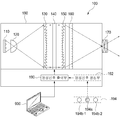
도 1은 본 발명의 바람직한 실시예에 따른 입체 영상 표시 장치(100)의 구성을 도시하는 도면이다.1 is a diagram illustrating a configuration of a stereoscopic
도 1을 참조하면, 본 발명의 입체 영상 표시 장치(100)는, 광원(110), 집광 렌즈(120), 제 1 변환 렌즈(130), 영상 신호 출력부(190), 투명 LCD 패널(140), 제 2 변환 렌즈(150), 렌즈 어레이(160), 및 투사 렌즈(170)를 포함하여 구성되고, 투사 렌즈(170)를 제외한 나머지 구성은 입체 영상 표시 장치(100)의 하우징(180) 내부에 수용된다.1, a stereoscopic
먼저, 광원(110)은 복수의 LED 램프로 구현되어 빛을 발생시킨다. 광원(110)에서 발생된 빛은 후술하는 구성요소들을 거쳐서 입체 영상 표시 장치(100)의 외부로 입체 영상을 투사하는 전체 빛을 제공한다.First, the
집광 렌즈(120)는 광원(110) 앞에 설치되어, 광원(110)에서 발생된 빛이 제 1 변환 렌즈(130) 전체 영역에 균일하게 조사되도록 한다. 본 발명의 바람직한 실시예에서 집광 렌즈(120)는 볼록 렌즈로 구현되었으나, 광원(110)에서 발생된 빛을 균일하게 제 1 변환 렌즈(130)로 조사할 수 있는 구성이라면 렌즈의 종류에 제한되지 않는다.The
제 1 변환 렌즈(130)는 집광렌즈(120)로부터 일정 거리만큼 이격되어 배치되고, 집광렌즈(120)를 통해서 입사된 빛을 평행광으로 변환하여 투명 LCD 패넬(140)로 조사한다. 본 발명의 바람직한 실시예에서는, 입체 영상 표시 장치(100)의 부피를 축소하기 위해서 제 1 변환 렌즈(130)를 프레넬(fresnel) 렌즈로 구현하였으나, 빛의 방향만 평행광으로 변환할 수 있다면 볼록 렌즈로 구현되어도 무방하다. 제 1 변환 렌즈(130)와 집광 렌즈(120)간의 이격 거리는 집광 렌즈(120)의 굴절율에 따라서 결정될 수 있고, 설계 사양에 따라서 이격 거리가 고정된 경우에는, 이격 거리에 대응되는 굴절율을 갖는 집광 렌즈(120)가 선택된다.The
영상 신호 출력부(190)는 컴퓨터와 같은 외부의 전자기기(900)와 연동되어, 외부의 전자기기(900)로부터 실시간으로 입력되는 입체 영상 신호를 투명 LCD 패널(140)로 출력한다. 본 발명의 바람직한 실시예에서 투명 LCD 패널(140)로 출력되는 입체 영상 신호는 깊이 정보가 반영되어 입체 영상을 표시하도록 생성된 집적 영상(integral imaging) 신호로서 입체 영상 신호에 대해서는 도 2를 참조하여 후술한다.The video
투명 LCD 패널(140)은 제 1 변환 렌즈(130)를 통과한 빛을 광원(110)으로 하여, 영상 신호 출력부(190)로부터 입력되는 집적 영상(integral imaging) 신호로 구현되는 입체 영상 신호를 디스플레이한다. 투명 LCD 패널(140)을 통해서 디스플레이되는 영상은 도 3에 도시된 바와 같이, 렌즈 어레이를 통해서 촬영된 영상으로서, 복수의 렌즈 각각을 통한 이미지는 다양한 시점의 영상을 표시하고 있음을 알 수 있다.The
투명 LCD 패널(140)은 이미 광고 수단으로 널리 이용되는 구성이므로 구체적인 설명은 생략하고, 투명 LCD 패널(140)로 입력되는 입체 영상 신호에 대해서는 도 2를 참조하여 후술한다.Since the
제 2 변환 렌즈(150)는 투명 LCD 패널(140)에서 디스플레이되는 영상을 렌즈 어레이(160)를 통과해서 투사렌즈(170)로 집광시키는 기능을 수행한다. 본 발명의 바람직한 실시예는 제 2 변환 렌즈(150)를 프레넬 렌즈로 구현함으로써 입체 영상 표시 장치(100)의 부피를 감소시켰다.The
렌즈 어레이(160)는 복수의 볼록 렌즈가 매트릭스 형태로 배치된 구조를 갖으며, 제 2 변환 렌즈(150)를 통과한 영상을 입체 영상으로 표시한다. 후술하는 바와 같이, 투명 LCD 패널(140)에 디스플레이되는 영상은, 원본 영상(더 정확하게는 깊이 정보가 반영된 깊이 차등 영상)을 가상의 렌즈 어레이를 통해서 본 영상으로서 각 렌즈마다 다양한 시점으로 객체를 바라본 영상이므로, 해당 영상을 동일한 렌즈 어레이(160)를 통과시키면 원본 영상을 복원할 수 있다. 따라서, 렌즈 어레이(160)는 입체 영상 신호를 생성할 때 이용된 렌즈 어레이(160)와 동일한 렌즈 어레이 또는 곡률 등의 파라미터가 동일한 것이 이용된다.The
이 때, 본 발명의 입체 영상은 깊이 정보가 반영된 이미지로서, 렌즈 어레이(160)를 통해서 표시되는 입체 영상은 객체의 형상에 따라서 영역마다 초점거리가 서로 다를 수 있다. 따라서, 본 발명은 홀로그램처럼 특정 공간에 서로 다른 깊이를 갖는 영상을 생성하여 출력할 수 있다.In this case, the stereoscopic image of the present invention is an image reflecting depth information, and the stereoscopic image displayed through the
렌즈 어레이(160)로부터 출력된 입체 영상은 투사 렌즈(170)를 통해서 입체 영상 표시 장치(100) 전면으로 확산되어 출력된다.
The stereoscopic image output from the
한편, 본 발명의 바람직한 다른 실시예에 따른 입체 영상 표시 장치(100)는 영상을 외부의 전자기기(900)로부터 입력받아 출력할 뿐만 아니라, 스스로 영상을 촬영하여 입체 영상 신호를 생성하는 구성을 더 포함할 수 있다.Meanwhile, the stereoscopic
도 1에 도시된 바와 같이, 본 발명의 바람직한 다른 실시예는 영상 촬영부(194) 및 영상 신호 생성부(192)를 포함한다.As shown in FIG. 1, another preferred embodiment of the present invention includes an
영상 촬영부(194)는 객체를 촬영하여 RGB 영상 및 깊이 영상을 생성하여 영상 신호 생성부(192)로 출력한다. 영상 촬영부(194)는 컬러 카메라(194a)와, IR 발신부(194b-1)와 IR 수신부(194b-2)로 구성되는 깊이 센서를 구비하여, RGB 영상과 깊이 영상을 동시에 촬영할 수 있는 마이크로소프트사의 kinect 로 구현될 수도 있고, RGB 영상과 깊이 영상을 각각 생성하는 별개의 카메라로 구현될 수도 있다.The
영상 신호 생성부(192)는 도 2를 참조하여 후술하는 바와 같이, 영상 촬영부(194)로부터 입력되는 RGB 영상 및 깊이 영상을 이용하여 입체 영상 신호를 생성하여 영상 신호 출력부(190)를 통해서 투명 LCD 패널(140)로 출력한다. 이 때, 영상 신호 생성부(192)는 RGB 영상에 포함되어 있던 픽셀값을 변경할 수도 있다.
2, the
도 2는 본 발명의 바람직한 실시예에 따라서 입체 영상 신호를 생성하는 과정을 설명하는 도면이다.2 is a diagram for explaining a process of generating a stereoscopic image signal according to a preferred embodiment of the present invention.
도 2를 참조하여, RGB 영상과 깊이 영상을 이용하여 입체 영상 신호를 생성하는 방법을 설명한다. 기본적으로, RGB 영상은 2차원 평면상에 각 픽셀마다 컬러값에 대응되는 RGB 값을 갖는 영상으로 구성되고, 깊이 영상은 RGB 영상의 각 픽셀에 대응되는 픽셀을 갖으며, 각 픽셀은 깊이값에 대응되는 픽셀값을 갖는다. 일반적으로 깊이 영상은 카메라로부터 가까운 위치일수록 밝게 표시되고(깊이값이 작고 픽셀값은 큼), 멀리 있는 위치일수록 어둡게 표시된다(깊이값은 크고 픽셀값은 작음). Referring to FIG. 2, a method of generating a stereoscopic image signal using an RGB image and a depth image will be described. Basically, an RGB image is composed of an image having an RGB value corresponding to a color value for each pixel on a two-dimensional plane, a depth image has pixels corresponding to each pixel of the RGB image, and each pixel has a depth value And have corresponding pixel values. In general, the depth image is displayed more brightly (the depth value is smaller and the pixel value is larger) and the farther away the image is darker (the depth value is larger and the pixel value is smaller).
RGB 영상과 깊이 영상을 이용하여 입체 영상 신호를 생성하기 위해서, 먼저, 깊이값이 0인 위치(z=0)에 가상의 렌즈 어레이(210)를 설정하고, 렌즈 어레이(210)로부터 일정한 간격으로 복수의 가상의 물체면(200-1~200-n)을 설정한다. In order to generate a stereoscopic image signal using the RGB image and the depth image, a
그 후, 깊이 영상의 각 픽셀에 대해서 순차적으로 픽셀값(깊이값)에 따라서 복수의 가상의 물체면(200-1~200-n) 중 어느 하나를 선택한다. 즉, 깊이값이 작을수록 가상의 렌즈 어레이(210)와 가까운 물체면이 선택되고, 깊이값이 클수록 가상의 렌즈 어레이(210)로부터 먼 물체면이 선택된다.Thereafter, one of a plurality of imaginary object planes 200-1 to 200-n is sequentially selected for each pixel of the depth image according to a pixel value (depth value). That is, the smaller the depth value, the closer the object plane is to the
그리고, 선택된 물체면에서 깊이 영상의 픽셀에 대응되는 위치에, RGB 영상의 대응되는 위치의 픽셀값을 설정하고, 상술한 과정을 모든 픽셀에 대해서 수행함으로써, 깊이 차등 영상을 생성한다.Then, a pixel value at a corresponding position of the RGB image is set at a position corresponding to the pixel of the depth image on the selected object plane, and the above-described process is performed on all the pixels to generate the depth difference image.
그 후, 깊이 차등 영상을 가상의 렌즈 어레이(210)에 투영한 영상을 소프트웨어적으로 촬영함으로써 깊이 정보가 반영된 입체 영상 신호를 생성한다.Thereafter, an image obtained by projecting the depth difference image onto the
상술한 바와 같이, 본 발명은 입체 영상 신호로 표시될 영상의 각 픽셀에 깊이 정보를 반영함으로써, 본 발명의 입체 영상 표시 장치(100)로 표시되는 입체 영상에 포함된 객체들은 서로 다른 깊이값을 갖고, 이에 따라서, 서로 다른 초점거리를 갖을 수 있다.
As described above, according to the present invention, depth information is reflected in each pixel of an image to be displayed as a stereoscopic image signal, so that objects included in a stereoscopic image displayed by the stereoscopic
도 3은 본 발명의 바람직한 일 실시예에 따라서 가상의 렌즈 어레이에 투영된 영상의 일예를 도시한 도면이다. 3 is a diagram showing an example of an image projected on a virtual lens array according to a preferred embodiment of the present invention.
도 3을 참조하면, 도 3의 (a)는 실험을 위해서 소프트웨어적으로 생성한 영상으로서, 흰색으로 씌여진 "DIYPRO"가 초록색 글씨로 씌여진"DIYPRO"보다 더 멀도록 깊이값이 설정되었고, 동일한 색의 글씨들의 깊이값은 동일하도록 설정되었다.Referring to FIG. 3, (a) in FIG. 3 is a software generated image for the experiment, in which depth values are set so that "DIYPRO" written in white is farther than "DIYPRO" written in green, The depth values of the letters of the same color were set to be the same.
도 3의 (b)는 도 2에 도시된 바와 같이, 깊이 차등 영상을 가상의 렌즈 어레이(210)에 투영한 후 촬영된 영상을 도시하는 것으로서, 도시된 바와 같이, 렌즈 어레이(210)에 포함된 각 렌즈들은 다양한 시점에서의 영상을 반영하고 있음을 알 수 있고, 이는 일반적인 집적영상(integral imaging) 방식과 동일하다.
FIG. 3 (b) is a view showing a photographed image after projecting the depth difference image onto the
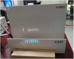
도 4는 도 3의 (b)에 도시된 영상을 본 발명의 입체 영상 표시 장치(100)를 이용하여 단일한 스크린 평면에 출력한 예를 도시하는 도면이다.FIG. 4 is a diagram showing an example of outputting the image shown in FIG. 3 (b) on a single screen plane using the stereoscopic
도 3을 참조하여 설명한 바와 같이, 흰색 글씨로 씌여진 "DIYPRO"와 초록색 글씨로 씌여진"DIYPRO"의 깊이값이 서로 다르게 설정되었으므로, 입체 영상에서 흰색 글씨로 씌여진"DIYPRO" 영역과 초록색 글씨로 씌여진"DIYPRO"영역은 서로 다른 초점거리를 갖게 되고, 투사 렌즈(170)와 스크린간의 거리를 조절함에 따라서, 초록색 글씨로 씌여진"DIYPRO"가 선명하게 출력되는 경우에는 흰색 글씨로 씌여진"DIYPRO"가 초점이 맞지 않아 흐리게 표시되고(도 4의 (a)참조), 흰색 글씨로 씌여진"DIYPRO"가 선명하게 출력되는 경우에는 초록색 글씨로 씌여진"DIYPRO"가 초점이 맞지 않아 흐리게 표시된다(도 4의 (b)참조).
As described with reference to FIG. 3, since the depth values of "DIYPRO" written in white letters and "DIYPRO" written in green letters are set to be different from each other, a "DIYPRO" area written in white letters and a green letter Quot; DIYPRO "areas written in white letters have different focal distances. When the distance between the
도 5는 서로 이격되도록 설치된 복수의 스크린에 도 3의 (a)에 도시된 영상이 표시된 예를 도시하는 도면이다. Fig. 5 is a diagram showing an example in which the image shown in Fig. 3 (a) is displayed on a plurality of screens provided so as to be spaced apart from each other.
도 5를 참조하면, 도 4와는 달리, 도 3의 (a)에서 깊이값이 작은 초록색 글씨는 앞에 설치된 스크린 1에 선명하게 표시되고, 깊이값이 큰 흰색 글씨는 뒤에 설치된 스크린 2에 선명하게 표시되는 것을 확인할 수 있다. 이러한 결과로부터, 본 발명의 바람직한 실시예에 따른 입체 영상 표시 장치(100)에서 출력되는 입체 영상은 원본 영상의 깊이값에 따라서 서로 다른 초점 거리를 갖도록 출력됨을 확인할 수 있다.
Referring to FIG. 5, unlike FIG. 4, a green color having a small depth value is clearly displayed on a
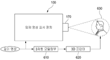
도 6은 본 발명의 바람직한 실시예에 따른 입체 영상 표시 장치(100)가 적용되는 일예를 나타내는 도면으로서, 본 발명의 입체 영상 표시 장치(100)를 이용하여 구현되는 조형물 투사 장치의 구성을 도시하는 도면이다. 6 is a diagram illustrating an example of application of the stereoscopic
도 6을 참조하면, 조형물 투사 장치는 도 1에 도시된 입체 영상 표시 장치(100), 깊이 영상으로부터 얻어지는 깊이 정보를 이용하여 입체 영상에 표시되는 객체에 대응되는 조형물을 3차원으로 모델링하는 3차원 모델링부(610), 및 3차원 모델링부(610)에서 생성된 3차원 모델링 정보에 따라서 상기 조형물을 직접 생성하는 3D 프린터(620)를 포함한다.Referring to FIG. 6, the stereographic projection apparatus includes a stereoscopic
깊이 영상의 각 픽셀의 깊이값과, 깊이 영상의 각 픽셀에 대응되도록 3D 프린터(620)에서 생성된 조형물(630)의 표면까지의 거리가 대응되도록, 조형물(630)과 입체 영상 표시 장치(100)간의 간격을 조정하여 깊이 영상의 초점 거리가 적절히 조절되면 조형물(630)에는 정확하게 초점거리가 일치되는 선명한 입체 영상이 매핑될 수 있다.
The 3D
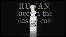
도 7a 내지 도 7c는 종래 기술에 따라서 조형물에 영상을 투사하는 방식을 설명하는 도면이다.Figs. 7A to 7C are diagrams for explaining a method of projecting an image onto a sculpture according to the prior art. Fig.
먼저, 도 7a 에 도시된 바와 같이, 조형물과 조형물 뒤쪽 배경에 영상을 투가하고자 하는 경우에, 조형물이 배경보다 앞에 위치하므로, 종래기술에서와 같이 하나의 영상을 투사하는 경우에는 배경과 조형물의 위치 차이로 초점이 안맞는 문제점이 존재하였다. 즉, 조형물에 초점이 맞도록 조절하면 배경에 표시되는 영상이 초점이 맞지 않아 뿌옅게 표시되고, 배경에 초점을 맞추면 조형물에 표시되는 영상이 초점이 맞지 않아 뿌옅게 표시되기 때문이다. First, as shown in FIG. 7A, in the case where an image is to be projected on the background behind the sculpture and the sculpture, since the sculpture is located in front of the background, when one image is projected as in the prior art, There was a problem that the focus was not suitable due to the position difference. That is, if the image is adjusted to be focused on the sculpture, the image displayed on the background is not focused, and the image displayed on the background is lightly displayed. If the background is focused, the image displayed on the sculpture is not focused.
이러한 문제를 해결하기 위해서, 종래 기술은 도 7b에 도시된 바와 같이 하나의 프로젝터를 이용하여 조형물 뒤의 배경에 글자로 구성된 영상을 표시하고, 다른 프로젝터를 이용하여 조형물상에 글자로 구성된 영상을 표시하며, 도 7c에 도시된 바와 같이, 또 다른 프로젝터를 이용하여 조형물의 얼굴 영상을 표시하였다. In order to solve this problem, in the related art, as shown in Fig. 7B, an image composed of letters is displayed on the background behind the molding using one projector, and an image composed of letters is displayed on the molding using another projector , And the face image of the sculpture was displayed using another projector as shown in FIG. 7C.
그러나, 도 7c의 얼굴 영상의 경우, 실제 얼굴 영상과 조형물에 형성된 굴곡이 매칭되지 않아, 즉, 깊이값이 서로 달라 얼굴이 어색하게 표현됨을 알 수 있다.However, in the case of the face image of FIG. 7C, it can be seen that the actual face image and the curvature formed on the sculpture are not matched, that is, the depth values are different from each other and the face is expressed in an awkward manner.
그러나, 본 발명의 입체 영상 표시 장치(100)는 깊이값에 따라서 초점 거리가 서로 다른 영역을 갖는 하나의 영상을 출력하므로, 도 7a 내지 도 7c 에 도시된 예의 경우, 하나의 입체 영상 표시 장치(100)만으로 조형물에 영상 투사가 가능하다.
However, since the stereoscopic
이제까지 본 발명에 대하여 그 바람직한 실시예들을 중심으로 살펴보았다. 본 발명이 속하는 기술 분야에서 통상의 지식을 가진 자는 본 발명이 본 발명의 본질적인 특성에서 벗어나지 않는 범위에서 변형된 형태로 구현될 수 있음을 이해할 수 있을 것이다. 그러므로 개시된 실시예들은 한정적인 관점이 아니라 설명적인 관점에서 고려되어야 한다. 본 발명의 범위는 전술한 설명이 아니라 특허청구범위에 나타나 있으며, 그와 동등한 범위 내에 있는 모든 차이점은 본 발명에 포함된 것으로 해석되어야 할 것이다.
The present invention has been described with reference to the preferred embodiments. It will be understood by those skilled in the art that various changes in form and details may be made therein without departing from the spirit and scope of the invention as defined by the appended claims. Therefore, the disclosed embodiments should be considered in an illustrative rather than a restrictive sense. The scope of the present invention is defined by the appended claims rather than by the foregoing description, and all differences within the scope of equivalents thereof should be construed as being included in the present invention.
100 입체 영상 표시 장치 110 광원
120 집광 렌즈 130 제 1 변환 렌즈
140 투명 LCD 패널 150 제 2 변환 렌즈
160 렌즈 어레이 170 투사 렌즈
180 하우징 190 영상 신호 출력부
192 영상 신호 생성부 194 영상 촬영부
194a 컬러 카메라 194b-1 IR 발신부
194b-2 IR 수신부 610 3차원 모델링부
620 3D 프린터 630 조형물
900 외부 전자기기100 stereoscopic
120
140
160
192
194b-2
620
900 External electronics
Claims (10)
상기 광원에서 발생된 빛이 제 1 변환 렌즈 전체 영역에 균일하게 조사되도록 하는 집광 렌즈;
상기 집광렌즈를 통과한 빛을 평행광으로 변환하는 상기 제 1 변환 렌즈;
집적 영상(integral imaging) 신호로 구현되는 입체 영상 신호를 출력하는 영상 신호 출력부;
상기 제 1 변환 렌즈를 통과한 빛을 광원으로 하여, 상기 입체 영상 신호를 디스플레이하는 투명 LCD 패널;
상기 투명 LCD 패널에서 디스플레이되는 영상을 렌즈 어레이로 집광시키는 제 2 변환 렌즈;
상기 제 2 변환 렌즈를 통과한 영상을 입체 영상으로 표시하는 상기 렌즈 어레이; 및
상기 렌즈 어레이로부터 출력된 입체 영상을 확산시키는 투사 렌즈를 포함하는 것을 특징으로 하는 입체 영상 표시 장치.A light source for generating light;
A condensing lens for uniformly irradiating light generated from the light source on the entire area of the first conversion lens;
A first conversion lens for converting light passing through the condenser lens into parallel light;
A video signal output unit for outputting a stereoscopic image signal embodied as an integral imaging signal;
A transparent LCD panel for displaying the stereoscopic image signal using light having passed through the first conversion lens as a light source;
A second conversion lens for condensing the image displayed on the transparent LCD panel into a lens array;
A lens array for displaying an image having passed through the second conversion lens as a stereoscopic image; And
And a projection lens for diffusing the stereoscopic image output from the lens array.
상기 렌즈 어레이는 상기 입체 영상 신호를 생성할 때 이용된 렌즈 어레이와 동일하거나, 동일한 파라미터를 갖는 것을 특징으로 하는 입체 영상 표시 장치.The method according to claim 1,
Wherein the lens array has the same or the same parameters as the lens array used when the stereoscopic image signal is generated.
상기 렌즈 어레이를 통과한 입체 영상은, 입체 영상으로 표시되는 객체의 형상에 따라서 초점 거리가 서로 다른 영역들이 존재하는 것을 특징으로 하는 입체 영상 표시 장치.The method according to claim 1,
Wherein the stereoscopic image passed through the lens array has areas of different focal distances depending on the shape of an object displayed as a stereoscopic image.
가상의 렌즈 어레이로부터 일정한 간격으로 복수의 가상의 물체면을 설정하고, 깊이 영상의 각 픽셀에 대해서 픽셀값에 따라서 복수의 가상의 물체면 중 어느 하나를 선택하고, 선택된 물체면의 상기 깊이 영상의 각 픽셀에 대응되는 위치에, RGB 영상의 대응되는 위치의 픽셀값을 설정함으로써, 깊이 차등 영상을 생성하고, 상기 깊이 차등 영상을 상기 가상의 렌즈 어레이에 투영한 영상을 이용하여 생성된 것을 특징으로 하는 입체 영상 표시 장치.The method of claim 1, wherein the stereoscopic image signal
A plurality of imaginary object planes are set at regular intervals from a virtual lens array and one of a plurality of imaginary object planes is selected for each pixel of the depth image in accordance with the pixel value, Generating a depth difference image by setting a pixel value at a corresponding position of the RGB image at a position corresponding to each pixel and projecting the depth difference image onto the virtual lens array, Dimensional image display device.
상기 입체 영상 신호를 생성하여 영상 신호 출력부로 제공하는 영상신호 생성부를 더 포함하고,
상기 영상신호 생성부는 입체 영상으로 표시할 객체의 RGB 영상 및 상기 객체의 깊이 정보를 포함하는 깊이 영상을 이용하여 상기 입체 영상 신호를 생성하는 것을 특징으로 하는 입체 영상 표시 장치.The method according to claim 1,
Further comprising a video signal generator for generating the stereoscopic video signal and providing the stereoscopic video signal to the video signal output unit,
Wherein the image signal generation unit generates the stereoscopic image signal using an RGB image of an object to be displayed as a stereoscopic image and a depth image including depth information of the object.
가상의 렌즈 어레이로부터 일정한 간격으로 복수의 가상의 물체면을 설정하고, 상기 깊이 영상의 각 픽셀에 대해서 픽셀값에 따라서 복수의 가상의 물체면 중 어느 하나를 선택하고, 선택된 물체면의 상기 깊이 영상의 각 픽셀에 대응되는 위치에, 상기 RGB 영상의 대응되는 위치의 픽셀값을 설정함으로써, 깊이 차등 영상을 생성하고, 상기 깊이 차등 영상을 상기 가상의 렌즈 어레이에 투영한 영상을 이용하여 상기 입체 영상 신호를 생성하는 것을 특징으로 하는 입체 영상 표시 장치.6. The apparatus of claim 5, wherein the image signal generator
A plurality of imaginary object planes are set at regular intervals from a virtual lens array and one of a plurality of imaginary object planes is selected for each pixel of the depth image in accordance with a pixel value, And generating a depth difference image by setting a pixel value at a corresponding position of the RGB image at a position corresponding to each pixel of the depth image, Wherein the signal generator generates a signal.
상기 RGB 영상 및 상기 깊이 영상을 촬영하여 상기 영상신호 생성부로 출력하는 영상 촬영부를 더 포함하는 것을 특징으로 하는 입체 영상 표시 장치.6. The method of claim 5,
Further comprising an image capturing unit capturing the RGB image and the depth image and outputting the captured RGB image and the depth image to the image signal generating unit.
상기 제 1 변환 렌즈 및 상기 제 2 변환 렌즈는 프레넬(fresnel) 렌즈로 구현되는 것을 특징으로 하는 입체 영상 표시 장치.
8. The method according to any one of claims 1 to 7,
Wherein the first conversion lens and the second conversion lens are implemented as a fresnel lens.
상기 깊이 정보에 따라서 상기 객체에 대응되는 조형물을 3차원으로 모델링하여 3차원 모델링 정보를 생성하는 3차원 모델링부; 및
상기 3차원 모델링 정보에 따라서 상기 조형물을 생성하는 3D 프린터를 포함하고,
상기 입체 영상 표시 장치는 상기 입체 영상과 상기 조형물이 대응되도록, 상기 투사 렌즈를 통과한 입체 영상을 상기 조형물에 조사하는 것을 특징으로 하는 조형물 투사 장치.A stereoscopic image display device according to any one of claims 5 to 7;
A three-dimensional modeling unit for modeling a model corresponding to the object in three dimensions according to the depth information to generate three-dimensional modeling information; And
And a 3D printer for generating the sculpture according to the 3D modeling information,
Wherein the stereoscopic image display device illuminates the stereoscopic image through the projection lens so that the stereoscopic image and the stereoscopic image correspond to each other.
상기 영상신호 생성부는 RGB 영상의 각 픽셀의 컬러값을 변형시켜 상기 입체 영상 신호를 생성하는 것을 특징으로 하는 조형물 투사 장치.10. The method of claim 9,
Wherein the image signal generator generates the stereoscopic image signal by modifying a color value of each pixel of the RGB image.
Priority Applications (1)
| Application Number | Priority Date | Filing Date | Title |
|---|---|---|---|
| KR1020160022478A KR101741227B1 (en) | 2016-02-25 | 2016-02-25 | Auto stereoscopic image display device |
Applications Claiming Priority (1)
| Application Number | Priority Date | Filing Date | Title |
|---|---|---|---|
| KR1020160022478A KR101741227B1 (en) | 2016-02-25 | 2016-02-25 | Auto stereoscopic image display device |
Publications (1)
| Publication Number | Publication Date |
|---|---|
| KR101741227B1 true KR101741227B1 (en) | 2017-05-29 |
Family
ID=59053240
Family Applications (1)
| Application Number | Title | Priority Date | Filing Date |
|---|---|---|---|
| KR1020160022478A Active KR101741227B1 (en) | 2016-02-25 | 2016-02-25 | Auto stereoscopic image display device |
Country Status (1)
| Country | Link |
|---|---|
| KR (1) | KR101741227B1 (en) |
Cited By (3)
| Publication number | Priority date | Publication date | Assignee | Title |
|---|---|---|---|---|
| CN108469684A (en) * | 2018-05-22 | 2018-08-31 | 成都工业学院 | A kind of transparent display and a kind of display system |
| CN115220240A (en) * | 2021-04-19 | 2022-10-21 | 幻景启动股份有限公司 | Method and display system for generating stereoscopic image data adapted to eye position |
| US12593021B2 (en) | 2023-06-28 | 2026-03-31 | Samsung Electronics Co., Ltd. | Electronic apparatus and method for controlling thereof |
Citations (1)
| Publication number | Priority date | Publication date | Assignee | Title |
|---|---|---|---|---|
| JP2010197473A (en) | 2009-02-23 | 2010-09-09 | Toda Constr Co Ltd | Three-dimensional projection exhibition device |
-
2016
- 2016-02-25 KR KR1020160022478A patent/KR101741227B1/en active Active
Patent Citations (1)
| Publication number | Priority date | Publication date | Assignee | Title |
|---|---|---|---|---|
| JP2010197473A (en) | 2009-02-23 | 2010-09-09 | Toda Constr Co Ltd | Three-dimensional projection exhibition device |
Cited By (5)
| Publication number | Priority date | Publication date | Assignee | Title |
|---|---|---|---|---|
| CN108469684A (en) * | 2018-05-22 | 2018-08-31 | 成都工业学院 | A kind of transparent display and a kind of display system |
| CN108469684B (en) * | 2018-05-22 | 2024-04-30 | 成都工业学院 | Transparent display and display system |
| CN115220240A (en) * | 2021-04-19 | 2022-10-21 | 幻景启动股份有限公司 | Method and display system for generating stereoscopic image data adapted to eye position |
| CN115220240B (en) * | 2021-04-19 | 2023-11-21 | 幻景启动股份有限公司 | Generating method and display system of stereoscopic image data adapted to eye position |
| US12593021B2 (en) | 2023-06-28 | 2026-03-31 | Samsung Electronics Co., Ltd. | Electronic apparatus and method for controlling thereof |
Similar Documents
| Publication | Publication Date | Title |
|---|---|---|
| CN1934874B (en) | Three-dimensional acquisition and visualization system for personal electronic devices | |
| CN103595989B (en) | Three-dimensional image display device and three-dimensional image processing method | |
| CN106170822B (en) | 3D light field camera and photography method | |
| CN102098524B (en) | Tracking type stereo display device and method | |
| WO2022119940A4 (en) | System and method for processing three dimensional images | |
| JP5450330B2 (en) | Image processing apparatus and method, and stereoscopic image display apparatus | |
| TW201333533A (en) | Display apparatuses and methods for simulating an autostereoscopic display device | |
| US10560683B2 (en) | System, method and software for producing three-dimensional images that appear to project forward of or vertically above a display medium using a virtual 3D model made from the simultaneous localization and depth-mapping of the physical features of real objects | |
| CN106210474A (en) | A kind of image capture device, virtual reality device | |
| CN107529054B (en) | Display screen, head-mounted display device, and display control method and device of head-mounted display device | |
| KR101741227B1 (en) | Auto stereoscopic image display device | |
| CN107155102A (en) | 3D automatic focusing display method and system thereof | |
| CN105898287A (en) | Device and method for machine visual analysis based on naked-eye stereoscopic display | |
| KR102112491B1 (en) | Method for description of object points of the object space and connection for its implementation | |
| KR20120093693A (en) | Stereoscopic 3d display device and method of driving the same | |
| CN101908233A (en) | Method and system for producing plural viewpoint picture for three-dimensional image reconstruction | |
| KR20160042694A (en) | Alignment device for stereoscopic camera and method thereof | |
| Zhang et al. | An interactive multiview 3D display system | |
| KR20130019582A (en) | 3-dimension camera using focus variable liquid lens applied and method of the same | |
| AU2006221912A1 (en) | 3D image capture camera and non-stereoscopic 3D viewing device that does not require glasses | |
| KR101093929B1 (en) | Method and system for displaying 3D image using depth map | |
| JP2006267767A (en) | Image display device | |
| KR101026686B1 (en) | Interactive stereoscopic image processing system and method, and interactive stereoscopic image processing apparatus | |
| TW201636683A (en) | Augmented reality imaging method and system | |
| CN113382225B (en) | A binocular holographic display method and device based on holographic sand table |
Legal Events
| Date | Code | Title | Description |
|---|---|---|---|
| PA0109 | Patent application |
Patent event code: PA01091R01D Comment text: Patent Application Patent event date: 20160225 |
|
| PA0201 | Request for examination | ||
| PE0902 | Notice of grounds for rejection |
Comment text: Notification of reason for refusal Patent event date: 20170215 Patent event code: PE09021S01D |
|
| PE0701 | Decision of registration |
Patent event code: PE07011S01D Comment text: Decision to Grant Registration Patent event date: 20170314 |
|
| GRNT | Written decision to grant | ||
| PR0701 | Registration of establishment |
Comment text: Registration of Establishment Patent event date: 20170523 Patent event code: PR07011E01D |
|
| PR1002 | Payment of registration fee |
Payment date: 20170523 End annual number: 3 Start annual number: 1 |
|
| PG1601 | Publication of registration | ||
| PR1001 | Payment of annual fee |
Payment date: 20210322 Start annual number: 5 End annual number: 5 |
|
| PR1001 | Payment of annual fee |
Payment date: 20220509 Start annual number: 6 End annual number: 6 |
|
| PR1001 | Payment of annual fee |
Payment date: 20230522 Start annual number: 7 End annual number: 7 |