KR101428376B1 - Apparatus for computing location of vehicle and method thereof - Google Patents
Apparatus for computing location of vehicle and method thereof Download PDFInfo
- Publication number
- KR101428376B1 KR101428376B1 KR1020130035630A KR20130035630A KR101428376B1 KR 101428376 B1 KR101428376 B1 KR 101428376B1 KR 1020130035630 A KR1020130035630 A KR 1020130035630A KR 20130035630 A KR20130035630 A KR 20130035630A KR 101428376 B1 KR101428376 B1 KR 101428376B1
- Authority
- KR
- South Korea
- Prior art keywords
- angle
- vehicle
- calculating
- micro
- slip
- Prior art date
- Legal status (The legal status is an assumption and is not a legal conclusion. Google has not performed a legal analysis and makes no representation as to the accuracy of the status listed.)
- Active
Links
- 238000000034 method Methods 0.000 title claims abstract description 21
- 230000001133 acceleration Effects 0.000 claims 2
- 239000000725 suspension Substances 0.000 abstract description 4
- 238000010586 diagram Methods 0.000 description 4
- 238000004364 calculation method Methods 0.000 description 2
- 238000005259 measurement Methods 0.000 description 2
- 238000004590 computer program Methods 0.000 description 1
- 238000010276 construction Methods 0.000 description 1
- 238000006073 displacement reaction Methods 0.000 description 1
- 238000012986 modification Methods 0.000 description 1
- 230000004048 modification Effects 0.000 description 1
- 229910052709 silver Inorganic materials 0.000 description 1
- 239000004332 silver Substances 0.000 description 1
Images


Classifications
-
- B—PERFORMING OPERATIONS; TRANSPORTING
- B60—VEHICLES IN GENERAL
- B60W—CONJOINT CONTROL OF VEHICLE SUB-UNITS OF DIFFERENT TYPE OR DIFFERENT FUNCTION; CONTROL SYSTEMS SPECIALLY ADAPTED FOR HYBRID VEHICLES; ROAD VEHICLE DRIVE CONTROL SYSTEMS FOR PURPOSES NOT RELATED TO THE CONTROL OF A PARTICULAR SUB-UNIT
- B60W30/00—Purposes of road vehicle drive control systems not related to the control of a particular sub-unit, e.g. of systems using conjoint control of vehicle sub-units
- B60W30/06—Automatic manoeuvring for parking
-
- B—PERFORMING OPERATIONS; TRANSPORTING
- B60—VEHICLES IN GENERAL
- B60W—CONJOINT CONTROL OF VEHICLE SUB-UNITS OF DIFFERENT TYPE OR DIFFERENT FUNCTION; CONTROL SYSTEMS SPECIALLY ADAPTED FOR HYBRID VEHICLES; ROAD VEHICLE DRIVE CONTROL SYSTEMS FOR PURPOSES NOT RELATED TO THE CONTROL OF A PARTICULAR SUB-UNIT
- B60W10/00—Conjoint control of vehicle sub-units of different type or different function
- B60W10/20—Conjoint control of vehicle sub-units of different type or different function including control of steering systems
-
- B—PERFORMING OPERATIONS; TRANSPORTING
- B60—VEHICLES IN GENERAL
- B60W—CONJOINT CONTROL OF VEHICLE SUB-UNITS OF DIFFERENT TYPE OR DIFFERENT FUNCTION; CONTROL SYSTEMS SPECIALLY ADAPTED FOR HYBRID VEHICLES; ROAD VEHICLE DRIVE CONTROL SYSTEMS FOR PURPOSES NOT RELATED TO THE CONTROL OF A PARTICULAR SUB-UNIT
- B60W2510/00—Input parameters relating to a particular sub-units
- B60W2510/20—Steering systems
-
- B—PERFORMING OPERATIONS; TRANSPORTING
- B60—VEHICLES IN GENERAL
- B60W—CONJOINT CONTROL OF VEHICLE SUB-UNITS OF DIFFERENT TYPE OR DIFFERENT FUNCTION; CONTROL SYSTEMS SPECIALLY ADAPTED FOR HYBRID VEHICLES; ROAD VEHICLE DRIVE CONTROL SYSTEMS FOR PURPOSES NOT RELATED TO THE CONTROL OF A PARTICULAR SUB-UNIT
- B60W2520/00—Input parameters relating to overall vehicle dynamics
- B60W2520/26—Wheel slip
Landscapes
- Engineering & Computer Science (AREA)
- Transportation (AREA)
- Mechanical Engineering (AREA)
- Chemical & Material Sciences (AREA)
- Combustion & Propulsion (AREA)
- Automation & Control Theory (AREA)
- Control Of Driving Devices And Active Controlling Of Vehicle (AREA)
- Steering Control In Accordance With Driving Conditions (AREA)
Abstract
본 발명은 차량의 위치 산출 장치 및 그 방법에 관한 것으로, 자동 주차 시스템에서 조향각과 전륜 타이어각 간의 상관관계를 나타내는 SPMD(Suspension Parameters Measuring Device) 특성 곡선은 물론 차량의 이동시 조향각으로 인해 발생하는 전륜 슬립각을 고려하여 차량의 위치를 산출함으로써, 자동 주차시 주차궤적을 보다 정확하게 추종할 수 있도록 하는 차량의 위치 산출 장치 및 그 방법을 제공하고자 한다.
이를 위하여, 본 발명은 차량의 위치 산출 장치에 있어서, 조향각에 상응하는 타이어각을 기록한 조향각-타이어각 테이블; 스티어링 휠에 의해 가변되는 조향각을 감지하는 조향각 감지부; 상기 조향각-타이어각 테이블을 기반으로, 상기 조향각 감지부에 의해 감지된 조향각에 상응하는 타이어각을 검색한 후 슬립각을 산출하는 슬립각 산출부; 상기 슬립각 산출부에 의해 산출된 슬립각을 기반으로 미소 요각도를 산출하는 미소 요각도 산출부; 및 상기 미소 요각도 산출부에 의해 산출된 미소 요각도를 기반으로, 슬립에 의해 발생하는 미소 이동이 반영된 차량의 현재 위치를 산출하는 위치 산출부를 포함한다.The present invention relates to an apparatus and method for calculating the position of a vehicle, and more particularly, to a suspension parameter measuring device (SPMD) characteristic curve showing a correlation between a steering angle and a front tire angle in an automatic parking system, And calculating a position of the vehicle in consideration of each angle so as to more accurately follow the parking locus at the time of automatic parking, and a method thereof.
To this end, the present invention provides a vehicle position calculating apparatus comprising: a steering angle-tire angle table in which a tire angle corresponding to a steering angle is recorded; A steering angle sensing unit for sensing a steering angle varying by the steering wheel; A slip angle calculating unit for calculating a slip angle after searching for a tire angle corresponding to the steering angle sensed by the steering angle sensing unit based on the steering angle-tire angle table; A micro-yaw angle calculating unit for calculating a micro-yaw angle based on the slip angle calculated by the slip angle calculating unit; And a position calculating unit for calculating a current position of the vehicle in which the micro-movement generated by the slip is reflected, based on the micro-yaw angle calculated by the micro-yaw angle calculating unit.
Description
본 발명은 차량의 위치 산출 장치 및 그 방법에 관한 것으로, 더욱 상세하게는 자동 주차시 전륜 타이어의 슬립각을 고려하여 차량의 위치를 산출함으로써, 주차궤적의 추종 정확도를 향상시킬 수 있도록 하는 차량의 위치 산출 장치 및 그 방법에 관한 것이다.
BACKGROUND OF THE
일반적으로, 주차가 미숙한 초보 운전자나 여성 운전자 또는 노약자들이 좁은 공간에 차량을 주차하는 경우, 주차하고자 하는 공간의 양측 또는 전후에 이미 주차된 차량과의 간격을 정확하게 예측하지 못하여 여러 번에 걸쳐 차량을 후진하거나 직진하여 차량을 주차하게 된다.Generally, when an inexperienced novice driver, a female driver or an elderly person parks a vehicle in a narrow space, it is difficult to precisely predict an interval between a parked vehicle on both sides of a space to be parked, The vehicle is parked.
이때 주변 차량과의 간격을 잘못 예측한 경우, 이미 주차된 차량과의 접촉 사고를 유발하거나 주변 차량과의 간격이 좁아 차량의 문을 정상적으로 열지 못하게 되는 경우가 빈번히 발생한다. 특히, 야간의 경우에는 사이드 미러나 백 미러를 통한 시야 확보가 주간에 비해 매우 어렵기 때문에 정상적으로 주차하기가 더욱더 어렵다.In this case, when the distance between the vehicle and the surrounding vehicle is incorrectly predicted, frequent occurrence of a contact accident with the already parked vehicle or the opening of the door of the vehicle frequently occurs due to a small distance from the surrounding vehicle. Especially, in the case of nighttime, it is much harder to park normally because securing a view through a side mirror or a back mirror is very difficult compared with a daytime.
이를 해결하기 위한 종래의 자동 주차 시스템은 각종 센서를 이용하여 수집한 정보를 기반으로 주차궤적을 생성한 후 해당 주차궤적을 추종하면서 차량을 원하는 공간에 위치시킨다. 이때 주차궤적을 추종하는데 필요한 조향각은 조향각 센서를 통해 수집한다.A conventional automatic parking system for solving this problem generates a parking locus based on collected information using various sensors, and places the vehicle in a desired space while following the parking locus. At this time, the steering angle required to follow the parking trajectory is collected through the steering angle sensor.
이러한 종래의 자동 주차 시스템은, 노면 조건에 따른 차량의 미끄러짐(슬립각, 슬립률), 조향각과 차륜각의 공차 등에 의해 발생하는 실질적인 조향각의 오차를 감안하지 않고, 단순히 조향각 센서를 통해 수집한 조향각을 이용하여 주차궤적을 추종하기 때문에 정확한 주차궤적 추종이 어려운 문제점이 있다.
Such a conventional automatic parking system has a problem in that it does not take into consideration an actual steering angle error caused by a slip (slip angle, slip ratio) of a vehicle according to road surface conditions, a tolerance of a steering angle and a wheel angle, There is a problem that it is difficult to follow the accurate parking trajectory because the parking trajectory is followed.
상기와 같은 종래 기술의 문제점을 해결하기 위하여, 본 발명은 자동 주차 시스템에서 조향각과 전륜 타이어각 간의 상관관계를 나타내는 SPMD(Suspension Parameters Measuring Device) 특성 곡선은 물론 차량의 이동시 조향각으로 인해 발생하는 전륜 슬립각을 고려하여 차량의 위치를 산출함으로써, 자동 주차시 주차궤적을 보다 정확하게 추종할 수 있도록 하는 차량의 위치 산출 장치 및 그 방법을 제공하는데 그 목적이 있다.In order to solve the problems of the prior art as described above, the present invention relates to a suspension parameter measuring device (SPMD) characteristic curve showing a correlation between a steering angle and a front tire angle in an automatic parking system, And calculating the position of the vehicle in consideration of each angle, thereby enabling the parking locus to be more accurately followed in the automatic parking.
본 발명의 목적들은 이상에서 언급한 목적으로 제한되지 않으며, 언급되지 않은 본 발명의 다른 목적 및 장점들은 하기의 설명에 의해서 이해될 수 있으며, 본 발명의 실시예에 의해 보다 분명하게 알게 될 것이다. 또한, 본 발명의 목적 및 장점들은 특허 청구 범위에 나타낸 수단 및 그 조합에 의해 실현될 수 있음을 쉽게 알 수 있을 것이다.
The objects of the present invention are not limited to the above-mentioned objects, and other objects and advantages of the present invention which are not mentioned can be understood by the following description, and will be more clearly understood by the embodiments of the present invention. It will also be readily apparent that the objects and advantages of the invention may be realized and attained by means of the instrumentalities and combinations particularly pointed out in the appended claims.
상기 목적을 달성하기 위한 본 발명의 장치는, 차량의 위치 산출 장치에 있어서, 조향각에 상응하는 타이어각을 기록한 조향각-타이어각 테이블; 스티어링 휠에 의해 가변되는 조향각을 감지하는 조향각 감지부; 상기 조향각-타이어각 테이블을 기반으로, 상기 조향각 감지부에 의해 감지된 조향각에 상응하는 타이어각을 검색한 후 슬립각을 산출하는 슬립각 산출부; 상기 슬립각 산출부에 의해 산출된 슬립각을 기반으로 미소 요각도를 산출하는 미소 요각도 산출부; 및 상기 미소 요각도 산출부에 의해 산출된 미소 요각도를 기반으로, 슬립에 의해 발생하는 미소 이동이 반영된 차량의 현재 위치를 산출하는 위치 산출부를 포함한다.According to another aspect of the present invention, there is provided an apparatus for calculating a position of a vehicle, comprising: a steering angle-tire angle table in which a tire angle corresponding to a steering angle is recorded; A steering angle sensing unit for sensing a steering angle varying by the steering wheel; A slip angle calculating unit for calculating a slip angle after searching for a tire angle corresponding to the steering angle sensed by the steering angle sensing unit based on the steering angle-tire angle table; A micro-yaw angle calculating unit for calculating a micro-yaw angle based on the slip angle calculated by the slip angle calculating unit; And a position calculating unit for calculating a current position of the vehicle in which the micro-movement generated by the slip is reflected, based on the micro-yaw angle calculated by the micro-yaw angle calculating unit.
또한 상기 목적을 달성하기 위한 본 발명의 방법은, 차량의 위치 산출 방법에 있어서, 조향각 감지부가 스티어링 휠에 의해 가변되는 조향각을 감지하는 단계; 슬립각 산출부가 상기 감지된 조향각에 상응하는 타이어각을 이용하여 슬립각을 산출하는 단계; 미소 요각도 산출부가 상기 산출된 슬립각을 기반으로 미소 요각도를 산출하는 단계; 및 위치 산출부가 상기 산출된 미소 요각도를 이용하여 슬립에 의해 발생하는 미소 이동이 반영된 차량의 현재 위치를 산출하는 단계를 포함한다.
According to another aspect of the present invention, there is provided a method for calculating a position of a vehicle, the method comprising: sensing a steering angle variable by a steering wheel sensing unit; Calculating a slip angle using a tire angle corresponding to the sensed steering angle; Calculating a micro-yaw angle based on the calculated slip angle; And calculating the current position of the vehicle in which the micro-movement generated by the slip is reflected using the calculated micro-yaw angle.
상기와 같은 본 발명은, 자동 주차 시스템에서 조향각과 전륜 타이어각 간의 상관관계를 나타내는 SPMD(Suspension Parameters Measuring Device) 특성 곡선은 물론 차량의 이동시 조향각으로 인해 발생하는 전륜 슬립각을 고려하여 차량의 위치를 산출함으로써, 자동 주차시 주차궤적을 보다 정확하게 추종할 수 있도록 하는 효과가 있다.
The present invention is not limited to the SPMD (Suspension Parameters Measuring Device) characteristic curve showing the correlation between the steering angle and the front tire angle in the automatic parking system, as well as the front slip angle caused by the steering angle when the vehicle is moving. It is possible to more accurately follow the parking locus at the time of automatic parking.
도 1 은 본 발명에 따른 차량의 위치 산출 장치에 대한 일실시예 구성도,
도 2 는 본 발명에 따른 SPMD 특성 곡선에 대한 일예시도,
도 3 은 본 발명에 따른 차량의 전륜 슬립각 산출 과정에 대한 일실시예 설명도,
도 4 및 도 5 는 본 발명에 따른 차량을 자전거 모델로 가정한 일예시도,
도 6 은 본 발명에 따른 차량의 위치 산출 방법에 대한 일실시예 흐름도이다.BRIEF DESCRIPTION OF THE DRAWINGS FIG. 1 is a block diagram of an apparatus for calculating a position of a vehicle according to an embodiment of the present invention;
FIG. 2 is an example of an SPMD characteristic curve according to the present invention,
FIG. 3 is an explanatory diagram of a front slip angle calculating process of a vehicle according to an embodiment of the present invention,
4 and 5 are views illustrating an example in which the vehicle according to the present invention is assumed to be a bicycle model,
6 is a flowchart of an embodiment of a method for calculating the position of a vehicle according to the present invention.
상술한 목적, 특징 및 장점은 첨부된 도면을 참조하여 상세하게 후술되어 있는 상세한 설명을 통하여 보다 명확해 질 것이며, 그에 따라 본 발명이 속하는 기술분야에서 통상의 지식을 가진 자가 본 발명의 기술적 사상을 용이하게 실시할 수 있을 것이다. 또한, 본 발명을 설명함에 있어서 본 발명과 관련된 공지 기술에 대한 구체적인 설명이 본 발명의 요지를 불필요하게 흐릴 수 있다고 판단되는 경우에 그 상세한 설명을 생략하기로 한다. 이하, 첨부된 도면을 참조하여 본 발명에 따른 바람직한 실시예를 상세히 설명하기로 한다.BRIEF DESCRIPTION OF THE DRAWINGS The above and other objects, features and advantages of the present invention will become more apparent from the following detailed description of the present invention when taken in conjunction with the accompanying drawings, It can be easily carried out. In the following description, well-known functions or constructions are not described in detail since they would obscure the invention in unnecessary detail. Hereinafter, preferred embodiments of the present invention will be described in detail with reference to the accompanying drawings.
도 1 은 본 발명에 따른 차량의 위치 산출 장치에 대한 일실시예 구성도이다.1 is a block diagram of an apparatus for calculating a position of a vehicle according to an embodiment of the present invention.
도 1에 도시된 바와 같이, 본 발명에 따른 차량의 위치 산출 장치는, 조향각-타이어각 테이블(11), 조향각 감지부(12), 슬립각(13), 미소 요각도 산출부(14), 및 위치 산출부(15)를 포함한다.1, the vehicle position calculating apparatus according to the present invention includes a steering angle-tire angle table 11, a steering
상기 각 구성요소들에 대해 살펴보면, 먼저 조향각-타이어각 테이블(11)은 스티어링 휠에 의해 발생하는 조향각에 상응하는 타이어각을 기록한 테이블이다. 일예로, 조향각-타이어각 테이블(11)은 도 2에 도시된 바와 같은 SPMD 특성 곡선을 포함한다. 도 2에서 ![]()
![]()
![]()
![]()
![]()
![]()
![]()
![]()
아울러, SPMD는 차량의 휠에 상/하 전/후 좌/우로 힘이나 변위를 가하여 서스펜션의 특성을 측정하는 유압시험장치인 차량기본특성시험기를 의미한다.In addition, SPMD refers to a vehicle basic characteristics tester, which is a hydraulic tester that measures the characteristics of a suspension by applying a force or a displacement to the wheel of the vehicle in the up / down / back / left / right direction.
다음으로, 조향각 감지부(12)는 일종의 조향각 감지 센서로서, 스티어링 휠에 의해 가변되는 조향각을 감지한다.Next, the steering
다음으로, 슬립각 산출부(13)는 조향각-타이어각 테이블(11)을 기반으로, 조향각 감지부(12)에 의해 감지된 조향각에 상응하는 타이어각을 이용하여 전륜 슬립각을 산출한다.Next, the slip
이하, 도 3 내지 도 5를 참조하여 슬립각 산출부(13)의 전륜 슬립각 산출 과정, 미소 요각도 산출부(14)의 미소 요각도 산출 과정, 위치 산출부(15)의 차량의 현재 위치 산출 과정에 대해 상세히 살펴보기로 한다.3 to 5, the process of calculating the front slip angle of the slip
도 3에서, '31'은 좌측 전륜, '32'는 우측 전륜, '33'은 좌측 전륜과 우측 전륜의 중앙에 위치한 가상의 전륜, '34'는 좌측 후륜, '35'는 우측 후륜, '36'은 좌측 후륜과 우측 후륜의 중앙에 위치한 가상의 후륜을 각각 의미한다.In FIG. 3,
아울러, lRL은 좌측 후륜(31)의 이동거리, lRR은 우측 후륜(32)의 이동거리, lRC는 가상의 후륜(36)의 이동거리, RRL은 좌측 후륜(31)의 선회반경, RRR은 우측 후륜의 선회반경, ![]()
![]()
![]()
![]()
![]()
![]()
![]()
![]()
![]()
![]()
![]()
![]()
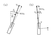
도 4 는 본 발명에 따른 차량을 자전거 모델로 가정한 일예시도이다.FIG. 4 is a diagram illustrating an example in which the vehicle according to the present invention is assumed to be a bicycle model.
도 4에서, (xF,yF)는 전륜의 xy 좌표, (xR,yR)은 후륜의 xy 좌표, vF는 전륜의 슬립각이 반영된 속도 벡터, ![]()
![]()
![]()
![]()
여기서, 슬립각을 구하기 위해 차량을 자전거 모델로 가정하면, ![]()
![]()
도 5에서, wssF는 전륜 휠속센서가 측정한 타이어 진행 방향의 휠속도, wssR은 후륜 휠속센서가 측정한 타이어 진행 방향의 휠속도를 각각 의미한다.In Figure 5, F is the wheel speed wss, wss R of the front wheel sensor measurements hwilsok Thai traveling direction refers to the wheel speed of the rear wheel tire proceeds hwilsok sensor measurement direction.
![]()
![]()
![]()
![]()
[수학식 1][Equation 1]

[수학식 2]&Quot; (2) "

이때, 후륜 슬립각(![]()
![]()
![]()
![]()
다음으로, 미소 요각도 산출부(14)는 슬립각 산출부(13)에 의해 산출된 슬립각을 기반으로 미소 요각도를 산출한다. 즉, 미소 요각도 산출부(14)는 애커만 지오메트리 관계식에 의해 성립하는 하기의 [수학식 3]을 이용하여 미소 요각도를 산출한다.Next, the micro-yaw
[수학식 3]&Quot; (3) "

다음으로, 위치 산출부(15)는 미소 요각도 산출부(14)에 의해 산출된 미소 요각도를 기반으로, 슬립에 의해 발생하는 미소 이동이 반영된 차량의 현재 위치(xVnew, yVnew, ![]()
![]()
[수학식 4]&Quot; (4) "

여기서, xVold는 차량의 직전 위치의 x좌표, yVold는 차량의 직전 위치의 y좌표, ![]()
![]()
또한, ![]()
![]()
![]()
![]()
도 6 은 본 발명에 따른 차량의 위치 산출 방법에 대한 일실시예 흐름도이다.6 is a flowchart of an embodiment of a method for calculating the position of a vehicle according to the present invention.
먼저, 조향각 감지부(12)가 스티어링 휠에 의해 가변되는 조향각을 감지한다(601).First, the steering
이후, 슬립각 산출부(13)가 조향각 감지부(12)에 의해 감지된 조향각에 상응하는 타이어각을 이용하여 슬립각을 산출한다(602).Then, the slip
이후, 미소 요각도 산출부(14)가 슬립각 산출부(13)에 의해 산출된 슬립각을 기반으로 미소 요각도를 산출한다(603).Subsequently, the micro-yaw
이후, 위치 산출부(15)가 미소 요각도 산출부(14)에 의해 산출된 미소 요각도를 기반으로, 슬립에 의해 발생하는 미소 이동이 반영된 차량의 현재 위치를 산출한다(604).Subsequently, the
이러한 과정을 통해 차량의 위치를 정확히 산출함으로써, 자동 주차시 주차궤적을 보다 정확하게 추종할 수 있도록 하는 장점이 있다.By accurately calculating the position of the vehicle through this process, it is possible to follow the parking locus more accurately in the automatic parking.
한편, 전술한 바와 같은 본 발명의 방법은 컴퓨터 프로그램으로 작성이 가능하다. 그리고 상기 프로그램을 구성하는 코드 및 코드 세그먼트는 당해 분야의 컴퓨터 프로그래머에 의하여 용이하게 추론될 수 있다. 또한, 상기 작성된 프로그램은 컴퓨터가 읽을 수 있는 기록매체(정보저장매체)에 저장되고, 컴퓨터에 의하여 판독되고 실행됨으로써 본 발명의 방법을 구현한다. 그리고 상기 기록매체는 컴퓨터가 판독할 수 있는 모든 형태의 기록매체를 포함한다.Meanwhile, the method of the present invention as described above can be written in a computer program. And the code and code segments constituting the program can be easily deduced by a computer programmer in the field. In addition, the created program is stored in a computer-readable recording medium (information storage medium), and is read and executed by a computer to implement the method of the present invention. And the recording medium includes all types of recording media readable by a computer.
이상에서 설명한 본 발명은, 본 발명이 속하는 기술 분야에서 통상의 지식을 가진 자에게 있어 본 발명의 기술적 사상을 벗어나지 않는 범위 내에서 여러 가지 치환, 변형 및 변경이 가능하므로 전술한 실시예 및 첨부된 도면에 의해 한정되는 것이 아니다.
It will be apparent to those skilled in the art that various modifications and variations can be made in the present invention without departing from the spirit or scope of the invention. The present invention is not limited to the drawings.
11 : 조향각-타이어각 테이블 12 : 조향각 감지부
13 : 슬립각 산출부 14 : 미소 요각도 산출부
15 : 위치 산출부11: Steering angle - Tire angle table 12: Steering angle sensor
13: slip angle calculating section 14: micro-yaw angle calculating section
15:
Claims (5)
스티어링 휠에 의해 가변되는 조향각을 감지하는 조향각 감지부;
상기 조향각-타이어각 테이블을 기반으로, 상기 조향각 감지부에 의해 감지된 조향각에 상응하는 타이어각을 검색한 후 슬립각을 산출하는 슬립각 산출부;
상기 슬립각 산출부에 의해 산출된 슬립각을 기반으로 미소 요각도를 산출하는 미소 요각도 산출부; 및
상기 미소 요각도 산출부에 의해 산출된 미소 요각도를 기반으로, 슬립에 의해 발생하는 미소 이동이 반영된 차량의 현재 위치를 산출하는 위치 산출부
를 포함하는 차량의 위치 산출 장치.
A steering angle-tire angle table in which a tire angle corresponding to the steering angle is recorded;
A steering angle sensing unit for sensing a steering angle varying by the steering wheel;
A slip angle calculating unit for calculating a slip angle after searching for a tire angle corresponding to the steering angle sensed by the steering angle sensing unit based on the steering angle-tire angle table;
A micro-yaw angle calculating unit for calculating a micro-yaw angle based on the slip angle calculated by the slip angle calculating unit; And
Based on the micro-yaw angle calculated by the micro-yaw angle calculating section, calculates a current position of the vehicle in which the micro-movement generated by the slip is reflected,
And calculates a position of the vehicle.
상기 슬립각 산출부는,
하기의 [수학식 A]를 이용하여 전륜 슬립각(
[수학식 A]

여기서,
The method according to claim 1,
Wherein the slip angle calculating unit calculates,
The front slip angle < RTI ID = 0.0 > ((A)
[Mathematical formula A]
here,
상기 미소 요각도 산출부는,
하기의 [수학식 B]를 이용하여 미소 요각도(
[수학식 B]

여기서, lRC = (좌측 후륜의 이동거리 + 우측 후륜의 이동거리)/2, L는 휠베이스를 각각 의미한다.
3. The method of claim 2,
Wherein the micro-
The micro-yaw angle ((B)
[Mathematical expression B]
Here, l RC = (The travel distance of the left rear wheel + the travel distance of the right rear wheel) / 2, and L denotes the wheel base.
상기 위치 산출부는,
하기의 [수학식 C]를 이용하여 차량의 위치(xVnew, yVnew,
[수학식 C]

여기서, xVold는 차량의 직전 위치의 x좌표, yVold는 차량의 직전 위치의 y좌표,
The method of claim 3,
The position calculating unit calculates,
( XVnew , yVnew , yVnew , yVnew , yVnew , yVnew) using the following formula (C)
[Mathematical expression C]
Here, xVold is the x coordinate of the position immediately before the vehicle, yVold is the y coordinate of the position immediately before the vehicle,
슬립각 산출부가 상기 감지된 조향각에 상응하는 타이어각을 이용하여 슬립각을 산출하는 단계;
미소 요각도 산출부가 상기 산출된 슬립각을 기반으로 미소 요각도를 산출하는 단계; 및
위치 산출부가 상기 산출된 미소 요각도를 이용하여 슬립에 의해 발생하는 미소 이동이 반영된 차량의 현재 위치를 산출하는 단계
를 포함하는 차량의 위치 산출 방법.
Sensing a steer angle that is varied by the steering angle sensor;
Calculating a slip angle using a tire angle corresponding to the sensed steering angle;
Calculating a micro-yaw angle based on the calculated slip angle; And
The position calculating unit calculates the present position of the vehicle in which the micro-movement generated by the slip is reflected using the calculated micro-yaw angle
Of the vehicle.
Priority Applications (1)
| Application Number | Priority Date | Filing Date | Title |
|---|---|---|---|
| KR1020130035630A KR101428376B1 (en) | 2013-04-02 | 2013-04-02 | Apparatus for computing location of vehicle and method thereof |
Applications Claiming Priority (1)
| Application Number | Priority Date | Filing Date | Title |
|---|---|---|---|
| KR1020130035630A KR101428376B1 (en) | 2013-04-02 | 2013-04-02 | Apparatus for computing location of vehicle and method thereof |
Publications (1)
| Publication Number | Publication Date |
|---|---|
| KR101428376B1 true KR101428376B1 (en) | 2014-08-07 |
Family
ID=51749937
Family Applications (1)
| Application Number | Title | Priority Date | Filing Date |
|---|---|---|---|
| KR1020130035630A Active KR101428376B1 (en) | 2013-04-02 | 2013-04-02 | Apparatus for computing location of vehicle and method thereof |
Country Status (1)
| Country | Link |
|---|---|
| KR (1) | KR101428376B1 (en) |
Cited By (3)
| Publication number | Priority date | Publication date | Assignee | Title |
|---|---|---|---|---|
| KR20170065365A (en) * | 2015-12-03 | 2017-06-13 | 현대자동차주식회사 | Apparatus and method for calculating active control value of integrated control system |
| CN114322978A (en) * | 2020-10-10 | 2022-04-12 | 广州汽车集团股份有限公司 | A vehicle positioning method, computer equipment, and computer-readable storage medium |
| KR20220125169A (en) * | 2021-03-04 | 2022-09-14 | 독터. 인제니어. 하.체. 에프. 포르쉐 악티엔게젤샤프트 | Method and apparatus for lane control of a vehicle |
Citations (2)
| Publication number | Priority date | Publication date | Assignee | Title |
|---|---|---|---|---|
| JP2005151658A (en) | 2003-11-13 | 2005-06-09 | Toyota Motor Corp | Vehicle control device |
| JP2010187480A (en) | 2009-02-12 | 2010-08-26 | Hitachi Constr Mach Co Ltd | Turning assisting device of electric vehicle |
-
2013
- 2013-04-02 KR KR1020130035630A patent/KR101428376B1/en active Active
Patent Citations (2)
| Publication number | Priority date | Publication date | Assignee | Title |
|---|---|---|---|---|
| JP2005151658A (en) | 2003-11-13 | 2005-06-09 | Toyota Motor Corp | Vehicle control device |
| JP2010187480A (en) | 2009-02-12 | 2010-08-26 | Hitachi Constr Mach Co Ltd | Turning assisting device of electric vehicle |
Cited By (6)
| Publication number | Priority date | Publication date | Assignee | Title |
|---|---|---|---|---|
| KR20170065365A (en) * | 2015-12-03 | 2017-06-13 | 현대자동차주식회사 | Apparatus and method for calculating active control value of integrated control system |
| KR102200524B1 (en) | 2015-12-03 | 2021-01-11 | 현대자동차주식회사 | Apparatus and method for calculating active control value of integrated control system |
| CN114322978A (en) * | 2020-10-10 | 2022-04-12 | 广州汽车集团股份有限公司 | A vehicle positioning method, computer equipment, and computer-readable storage medium |
| CN114322978B (en) * | 2020-10-10 | 2024-03-15 | 广州汽车集团股份有限公司 | A vehicle positioning method, computer equipment, and computer-readable storage medium |
| KR20220125169A (en) * | 2021-03-04 | 2022-09-14 | 독터. 인제니어. 하.체. 에프. 포르쉐 악티엔게젤샤프트 | Method and apparatus for lane control of a vehicle |
| KR102712993B1 (en) | 2021-03-04 | 2024-10-07 | 독터. 인제니어. 하.체. 에프. 포르쉐 악티엔게젤샤프트 | Method and apparatus for lane control of a vehicle |
Similar Documents
| Publication | Publication Date | Title |
|---|---|---|
| EP3405374B1 (en) | Deceleration curb-based direction checking and lane keeping system for autonomous driving vehicles | |
| CN110307850A (en) | Reckoning localization method and automated parking system | |
| JP2021049969A (en) | Systems and methods for calibrating steering wheel neutral position | |
| CN103213582A (en) | Anti-rollover warning control method based on vehicle roll angle estimation | |
| US9561803B2 (en) | Method for calculating a desired yaw rate for a vehicle | |
| JP6020729B2 (en) | Vehicle position / posture angle estimation apparatus and vehicle position / posture angle estimation method | |
| JP2005098853A (en) | Map data updating method and map data updating apparatus | |
| CN104648403A (en) | Method, apparatus and system for detecting narrow road | |
| JP4406608B2 (en) | Method for detecting geometric shape data for vehicle parking process | |
| JP2009012493A (en) | Vehicle driving assistance device | |
| JP5282590B2 (en) | Vehicle driving support device and vehicle driving support method | |
| KR102081513B1 (en) | Method and apparatus for measuring road condition using vehicle | |
| KR20140104611A (en) | Apparatus for automatic parking of vehicle and method using the same | |
| CN110073172A (en) | For determining the method for the relative position of motor vehicle, for the position determination system and motor vehicle of motor vehicle | |
| CN110356406A (en) | Method and system for handling the conditions of the road on which a vehicle travels | |
| KR101733880B1 (en) | Apparatus and method for estimating position of vehicle using nonlinear tire model | |
| CN104709280A (en) | Vehicle anti-collision system and method | |
| KR101428376B1 (en) | Apparatus for computing location of vehicle and method thereof | |
| KR20200052997A (en) | Apparatus of straight driving recognition for autonomous vehicle dead-reckoning performance improvement, and method thereof | |
| CN114212078B (en) | A method and system for detecting self-vehicle positioning accuracy in automatic parking | |
| JP6115429B2 (en) | Own vehicle position recognition device | |
| JP6169270B2 (en) | Method and apparatus for identifying running state of external vehicle | |
| KR101241518B1 (en) | Apparatus and method for computing steering angle with moving distance of rear wheel | |
| KR102046994B1 (en) | Estimation method of longitudinal and lateral road angle, and center of gravity position of vehicle and apparatus using the same | |
| CN115320606A (en) | A lane line estimation method and related device |
Legal Events
| Date | Code | Title | Description |
|---|---|---|---|
| PA0109 | Patent application |
Patent event code: PA01091R01D Comment text: Patent Application Patent event date: 20130402 |
|
| PA0201 | Request for examination | ||
| E701 | Decision to grant or registration of patent right | ||
| PE0701 | Decision of registration |
Patent event code: PE07011S01D Comment text: Decision to Grant Registration Patent event date: 20140624 |
|
| GRNT | Written decision to grant | ||
| PR0701 | Registration of establishment |
Comment text: Registration of Establishment Patent event date: 20140801 Patent event code: PR07011E01D |
|
| PR1002 | Payment of registration fee |
Payment date: 20140801 End annual number: 3 Start annual number: 1 |
|
| PG1601 | Publication of registration | ||
| FPAY | Annual fee payment |
Payment date: 20180730 Year of fee payment: 5 |
|
| PR1001 | Payment of annual fee |
Payment date: 20180730 Start annual number: 5 End annual number: 5 |
|
| FPAY | Annual fee payment |
Payment date: 20190729 Year of fee payment: 6 |
|
| PR1001 | Payment of annual fee |
Payment date: 20190729 Start annual number: 6 End annual number: 6 |
|
| PR1001 | Payment of annual fee |
Payment date: 20200729 Start annual number: 7 End annual number: 7 |
|
| PR1001 | Payment of annual fee |
Payment date: 20210728 Start annual number: 8 End annual number: 8 |
|
| PR1001 | Payment of annual fee |
Payment date: 20220727 Start annual number: 9 End annual number: 9 |
|
| PR1001 | Payment of annual fee |
Payment date: 20230801 Start annual number: 10 End annual number: 10 |
|
| PR1001 | Payment of annual fee |
Payment date: 20240725 Start annual number: 11 End annual number: 11 |