KR101419559B1 - Apparatus and method for transmitting signals in a multi-carrier system, apparatus and method for receiving signals in a multi-carrier system, frame pattern of a multi-carrier system, and systems and methods for transmitting and receiving signals - Google Patents
Apparatus and method for transmitting signals in a multi-carrier system, apparatus and method for receiving signals in a multi-carrier system, frame pattern of a multi-carrier system, and systems and methods for transmitting and receiving signals Download PDFInfo
- Publication number
- KR101419559B1 KR101419559B1 KR1020090095641A KR20090095641A KR101419559B1 KR 101419559 B1 KR101419559 B1 KR 101419559B1 KR 1020090095641 A KR1020090095641 A KR 1020090095641A KR 20090095641 A KR20090095641 A KR 20090095641A KR 101419559 B1 KR101419559 B1 KR 101419559B1
- Authority
- KR
- South Korea
- Prior art keywords
- data
- signaling
- frame
- pattern
- patterns
- Prior art date
- Legal status (The legal status is an assumption and is not a legal conclusion. Google has not performed a legal analysis and makes no representation as to the accuracy of the status listed.)
- Expired - Fee Related
Links
Images


Classifications
-
- H—ELECTRICITY
- H04—ELECTRIC COMMUNICATION TECHNIQUE
- H04L—TRANSMISSION OF DIGITAL INFORMATION, e.g. TELEGRAPHIC COMMUNICATION
- H04L5/00—Arrangements affording multiple use of the transmission path
- H04L5/003—Arrangements for allocating sub-channels of the transmission path
- H04L5/0048—Allocation of pilot signals, i.e. of signals known to the receiver
- H04L5/005—Allocation of pilot signals, i.e. of signals known to the receiver of common pilots, i.e. pilots destined for multiple users or terminals
-
- H—ELECTRICITY
- H04—ELECTRIC COMMUNICATION TECHNIQUE
- H04N—PICTORIAL COMMUNICATION, e.g. TELEVISION
- H04N7/00—Television systems
- H04N7/015—High-definition television systems
-
- H—ELECTRICITY
- H04—ELECTRIC COMMUNICATION TECHNIQUE
- H04L—TRANSMISSION OF DIGITAL INFORMATION, e.g. TELEGRAPHIC COMMUNICATION
- H04L25/00—Baseband systems
- H04L25/02—Details ; arrangements for supplying electrical power along data transmission lines
- H04L25/0202—Channel estimation
- H04L25/0224—Channel estimation using sounding signals
- H04L25/0226—Channel estimation using sounding signals sounding signals per se
-
- H—ELECTRICITY
- H04—ELECTRIC COMMUNICATION TECHNIQUE
- H04L—TRANSMISSION OF DIGITAL INFORMATION, e.g. TELEGRAPHIC COMMUNICATION
- H04L27/00—Modulated-carrier systems
- H04L27/26—Systems using multi-frequency codes
- H04L27/2601—Multicarrier modulation systems
- H04L27/2602—Signal structure
- H04L27/261—Details of reference signals
- H04L27/2613—Structure of the reference signals
-
- H—ELECTRICITY
- H04—ELECTRIC COMMUNICATION TECHNIQUE
- H04L—TRANSMISSION OF DIGITAL INFORMATION, e.g. TELEGRAPHIC COMMUNICATION
- H04L27/00—Modulated-carrier systems
- H04L27/26—Systems using multi-frequency codes
- H04L27/2601—Multicarrier modulation systems
- H04L27/2647—Arrangements specific to the receiver only
- H04L27/2655—Synchronisation arrangements
-
- H—ELECTRICITY
- H04—ELECTRIC COMMUNICATION TECHNIQUE
- H04L—TRANSMISSION OF DIGITAL INFORMATION, e.g. TELEGRAPHIC COMMUNICATION
- H04L5/00—Arrangements affording multiple use of the transmission path
- H04L5/003—Arrangements for allocating sub-channels of the transmission path
- H04L5/0058—Allocation criteria
- H04L5/0064—Rate requirement of the data, e.g. scalable bandwidth, data priority
Landscapes
- Engineering & Computer Science (AREA)
- Signal Processing (AREA)
- Computer Networks & Wireless Communication (AREA)
- Power Engineering (AREA)
- Multimedia (AREA)
- Mobile Radio Communication Systems (AREA)
- Synchronisation In Digital Transmission Systems (AREA)
- Time-Division Multiplex Systems (AREA)
Abstract
본 발명은 각각의 프레임이 적어도 하나의 시그널링 패턴 및 하나 이상의 데이터 패턴들을 포함하는 프레임 구조에 기초하여 멀티-캐리어 시스템에서 신호를 송신하기 위한 송신 장치(82)에 관한 것으로, 상기 송신 장치(82)는 프레임 내의 상기 적어도 하나의 시그널링 패턴에 제1 시그널링 데이터를 배열하도록 구성되고, 프레임 내의 상기 하나 이상의 데이터 패턴들에 데이터를 배열하도록 구성되는 프레임 형성 수단(59)-상기 하나 이상의 데이터 패턴들의 데이터는 데이터 프레임들에 배열되고, 각각의 데이터 프레임은 제2 시그널링 데이터 및 콘텐츠 데이터를 포함함-; 상기 적어도 하나의 시그널링 패턴 및 상기 하나 이상의 데이터 패턴을 주파수 영역으로부터 시간 영역으로 변환하여 시간 영역 송신 신호를 생성하도록 구성된 변환 수단(60); 및 상기 시간 영역 송신 신호를 송신하도록 구성된 송신 수단(61)을 포함한다.The present invention relates to a transmitting device (82) for transmitting signals in a multi-carrier system based on a frame structure in which each frame comprises at least one signaling pattern and one or more data patterns, Frame arranging means (59) arranged to arrange the first signaling data in the at least one signaling pattern in a frame and to arrange data in the one or more data patterns in a frame, the data of the one or more data patterns Arranged in data frames, each data frame including second signaling data and content data; Conversion means (60) configured to convert the at least one signaling pattern and the at least one data pattern from a frequency domain to a time domain to generate a time domain transmission signal; And transmission means (61) configured to transmit the time domain transmission signal.
본 발명은 또한 대응하는 송신 방법 및 프레임 구조뿐 아니라, 수신 장치 및 방법, 및 신호들을 송신 및 수신하기 위한 시스템 및 방법에도 관한 것이다.The present invention also relates to a receiving apparatus and method, as well as a corresponding transmitting method and frame structure, and to a system and method for transmitting and receiving signals.
멀티-캐리어 시스템, 프레임 구조, 시그널링 패턴, 데이터 패턴, 주파수 영역, 시간 영역 송신 신호 A multi-carrier system, a frame structure, a signaling pattern, a data pattern, a frequency domain,
Description
본 발명은 멀티-캐리어 시스템의 새로운 프레임 및 데이터 패턴 구조에 관한 것이다.The present invention relates to a new frame and data pattern structure in a multi-carrier system.
본 발명은 주로, 케이블 기반(cable-based) 또는 지상파 디지털 방송 시스템 등의 방송 시스템(이것에만 한정되는 것은 아님)에 관한 것으로, 이런 방송 시스템에서는 콘텐츠 데이터, 시그널링 데이터, 파일럿 신호 등이 복수의 주파수 캐리어들에 매핑된 후, 주어진 전체 또는 완전한 송신 대역폭에서 송신된다. 수신기는 전형적으로 완전한 채널 대역폭 중 일부 채널(전체 송신 대역폭의 일부)에 동조하여(때로는, 세그먼트된 수신이라고함) 각각의 수신기가 필요로 하거나 원하는 콘텐츠 데이터만을 수신한다. 예를 들면, ISDB-T 규격에서, 전체 채널 대역폭은 동일한 길이의 13개의 일정한 세그먼트(동일한 개수의 주파수 캐리어들)로 분할된다.The present invention mainly relates to (but not limited to) a broadcasting system such as a cable-based or terrestrial digital broadcasting system. In such a broadcasting system, contents data, signaling data, Mapped to carriers, and then transmitted in a given full or complete transmission bandwidth. The receiver typically tunes to some of the channels (part of the total transmission bandwidth) of the full channel bandwidth (sometimes referred to as segmented reception) to receive only the content data that each receiver needs or desires. For example, in the ISDB-T standard, the total channel bandwidth is divided into 13 constant segments (the same number of frequency carriers) of equal length.
본 발명의 목적은 송신 대역폭 중 요구된 임의의 부분에 유연하게 동조가능하며 낮은 오버헤드를 갖는, 송신 장치 및 방법, 또한 멀티-캐리어 시스템의 신호 구조를 제공하는 데에 있다.It is an object of the present invention to provide a transmitting apparatus and method, and also a signal structure of a multi-carrier system, which can flexibly tune to any desired part of the transmission bandwidth and have a low overhead.
본 발명의 상기 목적은 청구항 1에 따른 송신 장치에 의해 달성된다. 본 발명의 송신 장치는, 각각의 프레임이 적어도 하나의 시그널링 패턴 및 하나 이상의 데이터 패턴들을 포함하는 프레임 구조에 기초하여 멀티-캐리어 시스템에서 신호들을 송신하도록 구성되고, 상기 송신 장치는, 프레임 내의 상기 적어도 하나의 시그널링 패턴에 제1 시그널링 데이터를 배열하도록 구성되고, 프레임 내의 상기 하나 이상의 데이터 패턴들에 데이터를 배열하도록 구성되는 프레임 형성 수단-상기 하나 이상의 데이터 패턴들의 데이터는 데이터 프레임들에 배열되고, 각각의 데이터 프레임은 제2 시그널링 데이터 및 콘텐츠 데이터를 포함함-, 상기 적어도 하나의 시그널링 패턴 및 상기 하나 이상의 데이터 패턴들을 주파수 영역(frequency domain)으로부터 시간 영역(time domain)으로 변환하여 시간 영역 송신 신호를 생성하도록 구성된 변환 수단, 및 상기 시간 영역 송신 신호를 송신하도록 구성된 송신 수단을 포함한다.The above object of the present invention is achieved by a transmitting apparatus according to claim 1. The transmitting apparatus of the present invention is configured to transmit signals in a multi-carrier system based on a frame structure in which each frame includes at least one signaling pattern and one or more data patterns, Frame arranging means arranged to arrange the first signaling data in one signaling pattern and to arrange data in the one or more data patterns in a frame, the data of the one or more data patterns being arranged in data frames, Wherein the at least one signaling pattern and the at least one data pattern are transformed from a frequency domain into a time domain to generate a time domain transmit signal, Conversions configured to generate Stage, and a transmission unit configured to transmit said time domain transmission signal.
본 발명의 상기 목적은 또한, 청구항 7에 따른 송신 방법으로 달성된다. 본 발명의 송신 방법은, 각각의 프레임이 적어도 하나의 시그널링 패턴 및 하나 이상의 데이터 패턴들을 포함하는 프레임 구조에 기초하여 멀티-캐리어 시스템에서 신 호들을 송신하도록 구성되며, 본 발명의 송신 방법은, 프레임 내의 상기 적어도 하나의 시그널링 패턴에 시그널링 데이터를 배열하는 단계, 프레임 내의 상기 하나 이상의 데이터 패턴들에 데이터를 배열하는 단계-상기 하나 이상의 데이터 패턴들의 데이터는 데이터 프레임들에 배열되고, 각각의 데이터 프레임은 제2 시그널링 데이터 및 콘텐츠 데이터를 포함함-, 상기 적어도 하나의 시그널링 패턴 및 상기 하나 이상의 데이터 패턴들을 주파수 영역으로부터 시간 영역으로 변환하여 시간 영역 송신 신호를 생성하는 단계, 및 상기 시간 영역 송신 신호를 송신하는 단계를 포함한다.The above object of the present invention is also achieved by a transmission method according to claim 7. The transmission method of the present invention is configured to transmit signals in a multi-carrier system based on a frame structure in which each frame includes at least one signaling pattern and one or more data patterns, Arranging the signaling data in the at least one signaling pattern in the frame, the data of the one or more data patterns being arranged in the data frames, Generating a time domain transmit signal by transforming the at least one signaling pattern and the one or more data patterns from a frequency domain to a time domain to generate a time domain transmit signal, .
본 발명의 상기 목적은 또한, 청구항 8에 따른 멀티-캐리어 시스템의 프레임 패턴으로 달성되며, 이 프레임 패턴은, 적어도 하나의 시그널링 패턴 및 하나 이상의 데이터 패턴들을 포함하며, 프레임 내의 상기 하나 이상의 데이터 패턴들에 데이터가 배열되고, 상기 하나 이상의 데이터 패턴들의 데이터는 데이터 프레임들에 배열되고, 각각의 데이터 프레임은 제2 시그널링 데이터 및 콘텐츠 데이터를 포함한다.This object of the invention is also achieved in a frame pattern of a multi-carrier system according to claim 8, wherein the frame pattern comprises at least one signaling pattern and one or more data patterns, Wherein data of the one or more data patterns is arranged in data frames, and each data frame includes second signaling data and content data.
본 발명의 상기 목적은 또한, 송신 대역폭 중 요구된 임의의 부분에 유연하게 동조가능하며 낮은 오버헤드를 갖는, 수신 장치 및 방법, 및 송신 및 수신 시스템 및 방법을 제공하는 데 있다.The object of the present invention is also to provide a receiving apparatus and method, and a transmitting and receiving system and method, which are capable of being flexibly tuned to any desired part of the transmission bandwidth and have a low overhead.
본 발명의 상기 목적은 청구항 9에 따른 송신 대역폭 내의 프레임 구조에 기초하여 멀티-캐리어 시스템에서 신호들을 수신하기 위한 수신 장치로 달성되며, 각각의 프레임은 제1 시그널링 데이터를 포함한 적어도 하나의 시그널링 패턴 및 하 나 이상의 데이터 패턴들을 포함하며, 상기 하나 이상의 데이터 패턴들의 데이터는 데이터 프레임들에 배열되고, 각각의 데이터 프레임은 제2 시그널링 데이터 및 콘텐츠 데이터를 포함하며; 상기 수신 장치는 상기 송신 대역폭 중 선택된 부분에 동조하여 이를 수신하도록 구성된 수신 수단-상기 송신 대역폭 중 상기 선택된 부분은 수신될 적어도 하나의 데이터 패턴을 커버함-, 수신된 데이터 프레임에 포함된 상기 제2 시그널링 데이터를 평가하도록 구성된 평가 수단, 및 상기 평가 결과에 기초하여 수신된 데이터 프레임의 주파수 캐리어들로부터 데이터를 디-매핑하도록(de-map) 구성된 데이터 디-매핑 수단을 포함한다.The above object of the present invention is achieved by a receiving apparatus for receiving signals in a multi-carrier system based on a frame structure within a transmission bandwidth according to
본 발명의 상기 목적은 또한, 청구항 14에 따른 송신 대역폭 내의 프레임 구조에 기초하여 멀티-캐리어 시스템에서 신호들을 수신하기 위한 수신 방법으로 달성되며, 각각의 프레임은 제1 시그널링 데이터를 포함한 적어도 하나의 시그널링 패턴 및 하나 이상의 데이터 패턴들을 포함하며, 상기 하나 이상의 데이터 패턴들의 데이터는 데이터 프레임들에 배열되고, 각각의 데이터 프레임은 제2 시그널링 데이터 및 콘텐츠 데이터를 포함하며; 상기 수신 방법은 상기 송신 대역폭 중 선택된 부분을 수신하는 단계-상기 송신 대역폭 중 상기 선택된 부분은 수신될 적어도 하나의 데이터 패턴을 커버함-, 수신된 데이터 프레임에 포함된 상기 제2 시그널링 데이터를 평가하는 단계, 및 상기 평가 결과에 기초하여 수신된 데이터 프레임의 주파수 캐리어들로부터 데이터를 디-매핑하는 단계를 포함한다.The above object of the present invention is also achieved by a receiving method for receiving signals in a multi-carrier system based on a frame structure within a transmission bandwidth according to
본 발명의 상기 목적은 또한, 청구항 15에 따른 신호들을 송신 및 수신하기 위한 시스템으로 달성되며, 상기 시스템은 각각의 프레임이 적어도 하나의 시그널 링 패턴 및 하나 이상의 데이터 패턴들을 포함하는 프레임 구조에 기초하여 멀티-캐리어 시스템에서 신호를 송신하기 위한 송신 장치를 포함하며; 상기 송신 장치는, 프레임 내의 상기 적어도 하나의 시그널링 패턴에 제1 시그널링 데이터를 배열하도록 구성되고, 프레임 내의 상기 하나 이상의 데이터 패턴들에 데이터를 배열하도록 구성되는 프레임 형성 수단-상기 하나 이상의 데이터 패턴들의 데이터는 데이터 프레임들에 배열되고, 각각의 데이터 프레임은 제2 시그널링 데이터 및 콘텐츠 데이터를 포함함-; 상기 적어도 하나의 시그널링 패턴 및 상기 하나 이상의 데이터 패턴들을 주파수 영역으로부터 시간 영역으로 변환하여 시간 영역 송신 신호를 생성하도록 구성된 변환 수단; 및 상기 시간 영역 송신 신호를 송신하도록 구성된 송신 수단을 포함하며, 상기 시스템은 상기 송신 장치로부터 상기 시간 영역 송신 신호를 수신하도록 구성된 본 발명에 따른 수신 장치를 더 포함한다.The above object of the present invention is also achieved with a system for transmitting and receiving signals according to claim 15, wherein the system is further configured to generate a signaling pattern based on a frame structure in which each frame comprises at least one signaling pattern and one or more data patterns A transmitting device for transmitting a signal in a multi-carrier system; Frame forming means configured to arrange the first signaling data in the at least one signaling pattern in a frame and to arrange data in the one or more data patterns in a frame, Are arranged in data frames, each data frame including second signaling data and content data; Conversion means configured to convert the at least one signaling pattern and the one or more data patterns from a frequency domain to a time domain to generate a time domain transmission signal; And transmission means configured to transmit the time domain transmission signal, the system further comprising a receiving device according to the present invention configured to receive the time domain transmission signal from the transmission device.
본 발명의 상기 목적은 또한, 청구항 16에 따른, 신호들을 송신 및 수신하기 위한 방법으로 달성되며, 상기 방법은 각각의 프레임이 적어도 하나의 시그널링 패턴 및 하나 이상의 데이터 패턴들을 포함하는 프레임 구조에 기초하여 멀티-캐리어 시스템에서 신호들을 송신하기 위한 송신 방법을 포함하며; 상기 송신 방법은 프레임 내의 상기 적어도 하나의 시그널링 패턴에 시그널링 데이터를 배열하는 단계, 프레임 내의 상기 하나 이상의 데이터 패턴들에 데이터를 배열하는 단계-상기 하나 이상의 데이터 패턴들의 데이터는 데이터 프레임에 배열되고, 각각의 데이터 프레임은 제2 시그널링 데이터 및 콘텐츠 데이터를 포함함-, 상기 적어도 하나의 시그널링 패턴 및 상기 하나 이상의 데이터 패턴들을 주파수 영역으로부터 시간 영역으 로 변환하여 시간 영역 송신 신호를 생성하는 단계, 및 상기 시간 영역 송신 신호를 송신하는 단계를 포함하며, 상기 방법은 상기 시간 영역 송신 신호를 수신하도록 구성된 본 발명에 따른 수신 방법을 더 포함한다.The above object of the present invention is also achieved by a method for transmitting and receiving signals according to
유리한 특징들이 종속항에 개시된다.Advantageous features are disclosed in the dependent claims.
따라서, 본 발명은 주파수 영역에서 프레임 구조 또는 프레임 패턴을 이용하는 멀티-캐리어 시스템을 제안한다. 주파수 영역에서, 각각의 프레임은 적어도 하나의 시그널링 패턴을 포함하고, 이 시그널링 패턴은 주파수 캐리어들 상에 배열되는 제1 시그널링 데이터를 갖는다. 적어도 하나의 시그널링 패턴은 주파수 캐리어들 상에 배열되는 추가의 파일럿 신호들을 가질 수 있다. 대안으로, 각 프레임은 (시간적으로) 적어도 하나의 시그널링 패턴 이전에 배열되는 전용 훈련 시퀀스(dedicated training sequence) 또는 패턴을 가질 수 있으며, 이에 의해 전용 훈련 시퀀스 또는 패턴은 오로지 파일럿 신호들만을 포함한다. 이 경우, 적어도 하나의 시그널링 패턴은 파일럿 신호들을 필요로 하지는 않지만, 가질 수는 있다. 또한, 각 프레임은 각 프레임 패턴에서 시간적으로 적어도 하나의 시그널링 패턴에 이어지는 하나 이상의 데이터 패턴들을 포함한다. 또한, 본 발명에 따르면, 주파수 영역에서 프레임의 하나 이상의 데이터 패턴들 각각은 데이터 패턴의 상기 데이터 중에 배열되는 적어도 하나의 파일럿 신호를 포함할 수 있다. 각 데이터 패턴 내의 적어도 하나의 파일럿 신호에 의해 수신 측에서는 데이터 패턴들 내의 데이터를 반송하는 주파수 캐리어들에 대한 채널 추정을 행할 수 있는데, 이는 주파수 영역의 시간/주파수 그리드에서의 파일럿 신호의 위치가 수신기에 알려져 있으므로 간단한 방식으로 행해질 수 있다.Accordingly, the present invention proposes a multi-carrier system using a frame structure or a frame pattern in the frequency domain. In the frequency domain, each frame includes at least one signaling pattern, which has first signaling data arranged on frequency carriers. The at least one signaling pattern may have additional pilot signals arranged on frequency carriers. Alternatively, each frame may have a dedicated training sequence or pattern (temporally) arranged before at least one signaling pattern, whereby the dedicated training sequence or pattern comprises solely pilot signals. In this case, at least one signaling pattern does not need but can have pilot signals. Further, each frame includes one or more data patterns that are temporally followed by at least one signaling pattern in each frame pattern. Also according to the present invention, each of the one or more data patterns of a frame in the frequency domain may comprise at least one pilot signal arranged in the data of the data pattern. At least one pilot signal in each data pattern can make channel estimation on frequency carriers carrying data in data patterns on the receiver side, because the position of the pilot signal in the frequency domain time / It can be done in a simple way.
본 발명은 데이터 프레임들 내의 하나 이상의 데이터 패턴들에 데이터를 배열하는 것을 제안하며, 여기서 각 데이터 프레임은 콘텐츠 데이터 및 제2 시그널링 데이터를 포함한다. 따라서, 본 발명은 시그널링 데이터의 배열(arrangement)과 송신 및 수신을 프레임 내의 적어도 하나의 시그널링 패턴에서 송신되는 제1 시그널링 데이터와, 데이터 프레임들에 배열되는 제2 시그널링 데이터로 분리하는 것을 제안한다. 이에 의해, 적어도 하나의 시그널링 패턴 각각에 각각 동일한 시그널링 데이터를 송신할 수 있다. 다시 말하면, 프레임에 여러 개의 시그널링 패턴들이 제공되면, 그 시그널링 패턴들 각각은 동일한 제1 시그널링 데이터를 포함할 수 있다. 따라서, 이들 시그널링 데이터는 프레임 전체에 대해 유효한 시그널링 데이터이다. 한편, 제2 시그널링 데이터는 각각의 데이터 프레임에 대해서만 유효한 시그널링 데이터를 포함한다. 이와 같이, 데이터 프레임의 변조, 코딩 및 다른 파라미터들은 개별적으로 제2 시그널링 데이터와 함께 시그널링될 수 있다. 그러므로, 본 발명은 시그널링 오버헤드의 관점에서 매우 유연하면서도 여전히 효과적인 시스템을 제안한다.The present invention proposes arranging data in one or more data patterns in data frames, wherein each data frame includes content data and second signaling data. Accordingly, the present invention proposes to arrange the signaling data arrangement and the transmission and reception into the first signaling data transmitted in at least one signaling pattern in the frame and the second signaling data arranged in the data frames. Thus, it is possible to transmit the same signaling data to each of at least one signaling pattern. In other words, if multiple signaling patterns are provided in a frame, each of the signaling patterns may include the same first signaling data. Therefore, these signaling data are valid signaling data for the entire frame. On the other hand, the second signaling data includes signaling data valid only for each data frame. As such, the modulation, coding, and other parameters of the data frame can be signaled separately with the second signaling data. Therefore, the present invention proposes a system that is very flexible and still effective in terms of signaling overhead.
주파수 영역을 시간 영역으로 변환하는 중에, 주파수 캐리어들로의, 하나 이상의 시그널링 패턴들의 제1 시그널링 데이터(및 최종적으로는 파일럿 신호들)의 매핑 및, 데이터 패턴들의 콘텐츠 데이터 및 제2 파일럿 신호들(및 최종적으로는 파일럿 신호들)의 매핑이 일어난다. 이런 변환은, 예를 들면, 역 푸리에 변환 수단 또는 임의의 다른 적합한 변환 수단에서 구현된다. 결과적으로 생성되는 시간 영역 신호에서, 각 프레임은 각각의 시그널링 심볼들(최종적으로는 훈련 심볼에 이어짐) 및 하나 이상의 데이터 심볼들을 포함하게 된다. 각 프레임 패턴은 주파수 방향으로 전체(entire or overall) 송신 대역을 커버한다. 수신 장치는, 수신 장치가 동조할 수 있는 송신 대역폭의 부분이 시그널링 패턴들 중 적어도 하나의 길이를 가질 경우에는, 송신 대역폭 중 원하는 임의의 부분에 자유롭고, 유연하고, 신속하게 동조할 수 있다. 이에 의해, 수신 장치는 항상 전체 시그널링 패턴의 제1 시그널링 데이터를 수신할 수 있으므로, 연속하는 데이터 패턴들의 수신에 필요한 물리 층 정보를 포함하는 제1 시그널링 데이터를 기반으로 하여 이용함에 의해, 데이터 패턴들은 수신 장치에서 수신될 수 있다. 각각의 시그널링 패턴이 제1 시그널링 데이터뿐만 아니라 파일럿 신호들을 포함하는 경우에는, 단지 파일럿 신호들로만 구성되는 훈련 패턴들 또는 전용 프리앰블들을 제공할 필요가 없는데, 이는 시그널링 패턴에 포함된 파일럿 신호들이 수신 장치에서 필요한 주파수 오프셋 검출 및 보상을 허용하여, 전체적인 오버헤드가 감소되기 때문이다. 그러나, 또한 시그널링 패턴들에 앞서는 파일럿 신호들을 갖는 훈련 패턴들에 전용 프리앰블들을 제공할 수 있으며, 이 경우에 시그널링 패턴들은 파일럿 신호들을 포함하지 않는다. 본 발명은 유선 시스템(cable based systems) 등을 포함하지만 이것에만 한정되는 것은 아닌, 다소 높은 신호 대 잡음비를 갖는 시스템들에서 특히 유리하다. 수신기가 송신 대역폭 중 원하는 임의의 부분에 유연하게 동조할 수 있더라도, 수신기는 본 발명에서 제안된 새로운 프레임 구조들로 인해 제1 시그널링 데이터 및 기타의 데이터(콘텐츠 데이터)를 항상 수신할 수 있다. 또한, 새로운 프레임 구조 로 인해, 송신 대역폭 중 원하는 부분으로의 수신 장치의 고속 동조가 가능하다. 콘텐츠 데이터는 데이터 프레임들-각각의 데이터 프레임은 콘텐츠 데이터 및 제1 시그널링 데이터를 포함함-에서 송신되므로, 수신 장치는 매우 유연하게 콘텐츠 데이터를 수신할 수 있는데, 이는 각각의 데이터 프레임에 포함된 제2 시그널링 데이터에 의해 각각의 데이터 프레임의 파라미터들의 개별 시그널링이 가능하기 때문이다.The mapping of the first signaling data (and finally the pilot signals) of the one or more signaling patterns to the frequency carriers and the mapping of the content data of the data patterns and the second pilot signals And finally the pilot signals). Such a transformation is implemented in, for example, inverse Fourier transform means or any other suitable transform means. In the resulting time-domain signal, each frame will contain respective signaling symbols (eventually followed by training symbols) and one or more data symbols. Each frame pattern covers the entire or overall transmission band in the frequency direction. The receiving device can freely, flexibly, and quickly synchronize to any desired portion of the transmission bandwidth if the portion of the transmission bandwidth that the receiving device is capable of tuning has at least one of the signaling patterns. Thereby, the receiving apparatus can always receive the first signaling data of the entire signaling pattern, and therefore, by using the first signaling data based on the first signaling data including the physical layer information necessary for receiving the continuous data patterns, May be received at the receiving device. If each signaling pattern includes pilot signals as well as first signaling data, there is no need to provide training patterns or dedicated preambles consisting solely of pilot signals, since the pilot signals included in the signaling pattern Allowing the necessary frequency offset detection and compensation, thereby reducing overall overhead. However, it is also possible to provide dedicated preambles with training patterns having pilot signals preceding the signaling patterns, in which case the signaling patterns do not include pilot signals. The present invention is particularly advantageous in systems with somewhat higher signal-to-noise ratios, including, but not limited to, cable based systems and the like. Although the receiver can flexibly tune to any desired portion of the transmission bandwidth, the receiver can always receive the first signaling data and other data (content data) due to the new frame structures proposed in the present invention. In addition, due to the new frame structure, high-speed tuning of the receiving apparatus to a desired portion of the transmission bandwidth is possible. Since the content data is transmitted in the data frames - each data frame including the content data and the first signaling data, the receiving device is able to receive the content data in a very flexible manner, 2 signaling data enables the individual signaling of the parameters of each data frame.
유리하게도, 제2 시그널링 데이터는 수신된 데이터 프레임 내의 데이터의 변조를 포함하며, 이에 의해 수신 장치의 평가 수단은 변조를 얻도록 구성되고, 데이터 디-매핑 수단은 얻어진 변조에 기초하여 수신된 데이터 프레임의 주파수 캐리어들로부터 콘텐츠 데이터의 복조를 행하도록 구성된다. 더 유리하게는, 제2 시그널링 데이터는 수신된 데이터 프레임 내의 콘텐츠 데이터의 에러 코딩을 포함하며, 이에 의해 수신 장치의 평가 수단은 에러 코딩을 얻고, 에러 코딩을 수신된 데이터 프레임의 콘텐츠 데이터에 대해 에러 디코딩을 행하도록 구성된 에러 디코딩 수단에 전달한다. Advantageously, the second signaling data comprises modulation of the data in the received data frame, whereby the evaluating means of the receiving device is configured to obtain modulation, and the data de-mapping means decodes the received data frame based on the obtained modulation To demodulate the content data from the frequency carriers. Advantageously, the second signaling data comprises error coding of the content data in the received data frame such that the evaluating means of the receiving device obtains error coding and applies error coding to the content data of the received data frame in error To an error decoding means configured to perform decoding.
더 유리하게도, 제2 시그널링 데이터는 접속 ID(connection identification)를 포함하며, 수신 장치의 상기 평가 수단은 접속 ID를 얻도록 구성된다. 접속 ID는, 예를 들면, 방송, 유니캐스트(unicast), 지점간(point-to-point) 통신 등에 관한 정보로서, 데이터 프레임 내의 콘텐츠 데이터가 수신 장치에 의해 수신되도록 의도된 것인지의 여부를 수신 장치가 확인할 수 있게끔 해준다.More advantageously, the second signaling data comprises a connection identification and the evaluation means of the receiving device is configured to obtain a connection ID. The connection ID is information on, for example, broadcast, unicast, point-to-point communication, and the like, whether or not content data in a data frame is intended to be received by the receiving apparatus Allows the device to verify.
더 유리하게도, 수신 장치는 수신된 데이터 프레임의 제2 시그널링 데이터에 포함된 동기화 시퀀스에 대해 상관(correlation)을 행하도록 구성된 상관 수단을 포함하며, 이에 의해 데이터 디-매핑 수단은 상관 결과에 기초하여 수신된 데이터 프레임의 주파수 캐리어들로부터 상기 콘텐츠 데이터를 디-매핑하도록 구성된다.Advantageously, the receiving device further comprises correlation means configured to perform a correlation on the synchronization sequence contained in the second signaling data of the received data frame, whereby the data de-mapping means determines And to de-map the content data from frequency carriers of the received data frame.
유리하게도, 각각의 데이터 프레임 내의 제2 시그널링 데이터는 데이터 프레임의 헤더에 배열된다. 더 유리하게는, 제2 시그널링 데이터는 동기화 시퀀스를 포함한다. 동기화 시퀀스는, 예를 들면, 의사-잡음 시퀀스, PRBS(의사 랜덤 2진 시퀀스) 또는 임의의 기타 적합한 시퀀스일 수 있다. 이로써, 유리하게도, 제2 시그널링 데이터는 심볼들에 배열되고, 상기 동기화 시퀀스의 일부는 각 심볼에 삽입된다. 이에 의해, 각 심볼의 최상위 비트는 상기 동기화 시퀀스의 상기 부분을 포함할 수 있다. 또한, 각 심볼의 다른 비트들은 상기 동기화 시퀀스의 상기 부분의 송신에 사용될 수 있다. 대안으로, 제2 시그널링 데이터는 심볼들에 배열되며, 상기 동기화 시퀀스의 일부는 각 심볼의 적어도 일부로 변조된다. 예를 들면, 각 심볼의 1비트는 동기화 시퀀스의 일 부분(예를 들면, 1비트)을 그것으로 변조시킬 수 있다.Advantageously, the second signaling data in each data frame is arranged in a header of the data frame. More advantageously, the second signaling data comprises a synchronization sequence. The synchronization sequence may be, for example, a pseudo-noise sequence, a PRBS (pseudorandom binary sequence) or any other suitable sequence. Advantageously, therefore, the second signaling data is arranged in symbols, and a part of the synchronization sequence is inserted in each symbol. Thereby, the most significant bit of each symbol may comprise the portion of the synchronization sequence. In addition, other bits of each symbol may be used for transmission of the portion of the synchronization sequence. Alternatively, the second signaling data is arranged in symbols, and a portion of the synchronization sequence is modulated to at least a portion of each symbol. For example, one bit of each symbol may modulate a portion of the synchronization sequence (e.g., one bit) with it.
따라서, 예를 들면, 수신 장치에서 올바른 상관을 가능하게 해주는 의사-잡음 시퀀스 또는 임의의 기타 적합한 시퀀스일 수 있는 동기화 시퀀스를 이용하여, 수신 장치는 데이터 프레임 내에서 제2 시그널링 데이터를 발견하고, 제2 시그널링 데이터의 콘텐츠를 평가한 후, 각각의 데이터 프레임에 포함된 콘텐츠 데이터를 디코딩, 복조 등을 행할 수 있다. 이것은 상기 데이터 패턴들 중 적어도 하나에 상기 데이터 패턴들 중 적어도 하나와 동일한 주파수 구조(프레임 내의 위치 및 주파 수 캐리어들의 개수)를 갖는 시간 차원의 적어도 하나의 추가 데이터 패턴이 이어지는 경우에 특히 필요하며(더 유리하며), 여기서 상기 데이터 패턴들 중 상기 적어도 하나 및 적어도 하나의 추가 데이터 패턴에 배열된 데이터 프레임들은 주파수 구조와는 독립적으로 서로 연속하여 배열된다. 다시 말하면, 데이터 프레임들은 데이터 패턴들 내에 배열되지만, 데이터 패턴들의 구조와 독립적이며 데이터 패턴들의 구조에만 한정되지는 않는 구조를 갖는다. 따라서, 동일한 주파수 구조를 가지며, 시간 차원에서 서로 연속되는(즉, 서로 정렬되는) 다수의 데이터 패턴들을 포함하는 프레임의 경우, 콘텐츠 데이터 및 제2 시그널링 데이터를 포함한 데이터 프레임들은 데이터 패턴들에서 자유롭고 유연하게 서로 연속하여 배열된다. 이에 의해, 각 데이터 프레임의 길이 및, 에러 코딩, 변조 등의 데이터 프레임의 파라미터들을 유연하게 설정하여 각 데이터 프레임에 이용될 수 있는데, 예를 들면, 각 데이터 프레임 또는 적어도 일부 데이터 프레임들마다 다를 수 있다. 이로써, 각각의 개별 데이터 프레임에 대한 각각의 파라미터 정보가 제2 시그널링 데이터에 포함되게 되어, 데이터 프레임 내의 콘텐츠 데이터는 수신 장치에서 적절히 수신, 디코딩, 복조 등의 처리가 행해질 수 있다. 또한, 제2 시그널링 데이터는 접속 ID 정보, 즉 각각의 데이터 프레임 내의 송신된 콘텐츠 데이터가 수신 장치에 의해 수신되는 것으로 의도된 것인지를 수신 장치가 확인가능하게 해주는 정보를 포함할 수 있다. 따라서, 방송 송신, 유니캐스트 송신, 지점간 송신 등은 본 발명에 의해 지원된다. 각 데이터 프레임 내의 제2 시그널링 데이터 내에 포함된 동기화 시퀀스를 이용하여, 수신 장치는 데이터 프레임 내에서 제2 시그널링 데이터를 발견하 고, 제2 시그널링 데이터의 콘텐츠를 평가한 후, 각각의 데이터 프레임에 포함된 콘텐츠 데이터를 디코딩, 복조 등을 행할 수 있다. 임의의 에러 및 실수를 피하려면, 각 데이터 프레임 내의 제2 시그널링 데이터는 강한(robust) 에러 코딩 방식(scheme) 및 강한 변조로 인코딩되는 것이 보장되어야 한다.Thus, for example, using a synchronization sequence that may be a pseudo-noise sequence or any other suitable sequence that allows for correct correlation at the receiving device, the receiving device finds the second signaling data in the data frame, 2 signaling data, the content data included in each data frame can be decoded, demodulated, and the like. This is particularly necessary if at least one of the data patterns is followed by at least one additional data pattern of a time dimension having the same frequency structure (at least one position in the frame and a number of frequency carriers) as at least one of the data patterns Wherein the data frames arranged in the at least one and at least one additional data pattern of the data patterns are arranged contiguous to each other independently of the frequency structure. In other words, the data frames are arranged in the data patterns, but have a structure that is independent of the structure of the data patterns and is not limited to the structure of the data patterns. Thus, in the case of a frame having a plurality of data patterns having the same frequency structure and continuing (i.e., aligned with each other) in the time dimension, the data frames including the content data and the second signaling data are free and flexible As shown in FIG. Thus, the length of each data frame and the parameters of the data frame, such as error coding and modulation, can be flexibly set and used for each data frame, for example, each data frame or at least some data frames have. As a result, the respective parameter information for each individual data frame is included in the second signaling data, and the contents data in the data frame can be appropriately received, decoded, demodulated, etc., in the receiving apparatus. In addition, the second signaling data may include connection ID information, i.e., information that allows the receiving device to verify whether the transmitted content data in each data frame is intended to be received by the receiving device. Thus, broadcast transmission, unicast transmission, point-to-point transmission, etc. are supported by the present invention. Using the synchronization sequence contained in the second signaling data in each data frame, the receiving device finds the second signaling data in the data frame, evaluates the content of the second signaling data, Demodulate, and so on. To avoid any errors and real numbers, the second signaling data in each data frame should be guaranteed to be encoded in a robust error coding scheme and strong modulation.
유리하게도, 적어도 하나의 데이터 패턴은 (주파수 방향으로) 최소 데이터 패턴 길이에 의해 결정되는데, 즉 최소 데이터 패턴 길이 또는 그 배수와 동일하다. 따라서, 프레임에 둘 이상의 또는 복수의 데이터 패턴들이 제공되는 경우, 데이터 패턴들은 상이한 길이를 가질 수 있다. 그러나, 데이터 패턴들의 길이는 언급한 최소 데이터 패턴 길이에 좌우된다. 그러므로, 데이터 패턴들의 길이가 가변적이거나 또는 가변적일 수 있더라도 오버헤드가 줄어드는데, 즉 송신 측으로부터 수신 측으로 송신될 필요가 있는 제1 시그널링 데이터의 양은 데이터 패턴 길이가 완전히 가변적이며 원하는 임의의 값으로 설정될 수 있는 시스템에 비해 감소된다. 각 데이터 패턴은 최소 데이터 패턴 길이 또는 그 배수와 동일하므로, 전체적인 송신 대역폭은 최소 데이터 패턴 길이의 배수일 수 있다.Advantageously, the at least one data pattern is determined by a minimum data pattern length (in the frequency direction), i. E. Equal to the minimum data pattern length or a multiple thereof. Thus, if two or more data patterns are provided in a frame, the data patterns may have different lengths. However, the length of the data patterns depends on the minimum data pattern length mentioned. Therefore, although the length of the data patterns may be variable or variable, the amount of overhead is reduced, i.e. the amount of the first signaling data that needs to be transmitted from the transmitting side to the receiving side is such that the data pattern length is completely variable and set to any desired value Compared to a system that can be used. Since each data pattern is equal to the minimum data pattern length or a multiple thereof, the overall transmission bandwidth may be a multiple of the minimum data pattern length.
유리하게는, 각 프레임은 주파수 캐리어들 상에 배열되는 제1 시그널링 데이터를 갖는 적어도 하나의 시그널링 패턴을 포함하며, 상기 제1 시그널링 데이터는 상기 최소 데이터 패턴 길이에 관련하여(또는 대하여) 상기 하나 이상의 데이터 패턴들 각각의 길이를 포함하며, 상기 수신 장치는 수신된 제1 시그널링 데이터로부터 상기 길이를 추출하도록 구성된 평가 수단을 더 포함한다. 더 유리하게도, 수신된 각각의 데이터 패턴 내의 파일럿 신호들의 개수는 수신된 상기 데이터 패턴에 포함된 최소 데이터 패턴 길이의 개수에 정비례하며, 여기서 상기 수신 장치의 상기 채널 추정 수단은 상기 파일럿 신호들에 기초하여 채널 추정을 행하도록 구성된다. 따라서, 최소 데이터 패턴 길이에, 특정 개수 및 고정 개수의 파일럿 신호들, 예를 들면, 하나의 파일럿 신호, 2개의 파일럿 신호들, 3개의 파일럿 신호들 또는 적당한 개수의 파일럿 신호들이 배치되어 포함되므로, 각각의 데이터 패턴은 그 주파수 캐리어들에 매핑되는 최종의 많은 파일럿 신호들을 갖는다.Advantageously, each frame comprises at least one signaling pattern having first signaling data arranged on frequency carriers, said first signaling data being associated with (or against) said minimum data pattern length, The length of each of the data patterns, and the receiving apparatus further comprises evaluation means configured to extract the length from the received first signaling data. Advantageously, the number of pilot signals in each received data pattern is directly proportional to the number of minimum data pattern lengths contained in the received data pattern, wherein said channel estimating means of said receiving device is based on said pilot signals So as to perform channel estimation. Therefore, since a specific number and a fixed number of pilot signals, for example, one pilot signal, two pilot signals, three pilot signals, or an appropriate number of pilot signals are disposed and included in the minimum data pattern length, Each data pattern has a number of final pilot signals that are mapped to the frequency carriers.
더 유리하게는, 파일럿 신호들은 하나 이상의 데이터 패턴들에 파일럿 신호 패턴으로 배열되며, 여기서 상기 최소 데이터 패턴 길이는 파일럿 패턴 내에서의 상기 파일럿 신호의 밀도에 좌우된다. 이에 의해, 파일럿 신호 패턴이란 용어는 프레임의 시간/주파수 그리드에서(주파수 영역에서) 파일럿 신호들의 일정한 구조 및 배열을 특징짓는 것으로 의도되며, 이로써, 전체 파일럿 신호 패턴 또는 그 중 적어도 일부는 시간 및/또는 주파수 방향으로 규칙적인 패턴으로 배열되는 파일럿 신호들을 포함한다. 유리하게도, 최소 데이터 패턴 길이는 파일럿 패턴 내에서의 파일럿 신호들의 밀도에 따라 좌우된다. 이에 의해, 파일럿 신호의 밀도가 낮을수록, 최소 데이터 패턴 길이는 커질 수 있으며, 또한 그 반대도 성립된다. 그러므로, 수신기 측에 대해 신뢰할 수 있는 채널 추정을 달성하기 위해 적은 파일럿 신호(저밀도의 파일럿 신호들)를 필요로 하는 시스템에서, 최소 데이터 패턴 길이는 높은 파일럿 신호 밀도를 필요로 하는 시스템에 비해 커질 수 있다. 유리하게는, 파일럿 신호 패턴 내의 파일럿 신호들은 주파수 방향으로 규칙적인 간격(spacing)을 가져, 최소 데이터 패턴 길이는 주파수 방향으로 인접하는 2개의 파일럿 신호 간의 간격에 대응한다. 이로써, 각 데이터 패턴은 확실하게 단일의 파일럿 신호만을 포함한다. 물론, 각 데이터 패턴에 둘 이상의 파일럿 신호들이 포함되도록 최소 데이터 패턴 길이를 선택할 수도 있다. 더 유리하게는, 각 데이터 패턴은 시간 방향에서 동일한 길이를 갖는다. 데이터 패턴 길이가 시간 방향에서 가변적일 수 있지만(반드시 가변적일 필요는 없다), 이런 유리한 옵션은 시간 방향(시간 영역이라 하기도 함)에서 동일한 길이를 갖는 각 데이터 패턴을 제공함을 암시한다. 이로써, 시간 방향으로의 데이터 패턴들의 길이는 유리하게도 시간 방향으로 인접하는 2개의 파일럿 신호들 간의 간격에 대응할 수 있다.More advantageously, the pilot signals are arranged in a pilot signal pattern in one or more data patterns, wherein the minimum data pattern length is dependent on the density of the pilot signal in the pilot pattern. By this, the term pilot signal pattern is intended to characterize a constant structure and arrangement of pilot signals (in the frequency domain) in the time / frequency grid of the frame, whereby the entire pilot signal pattern, or at least some of it, Or pilot signals arranged in a regular pattern in the frequency direction. Advantageously, the minimum data pattern length is dependent on the density of the pilot signals in the pilot pattern. Thereby, the lower the density of the pilot signal, the larger the minimum data pattern length, and vice versa. Therefore, in a system that requires a small pilot signal (low-density pilot signals) to achieve reliable channel estimation for the receiver side, the minimum data pattern length can be large compared to systems that require high pilot signal densities have. Advantageously, the pilot signals in the pilot signal pattern have regular spacing in the frequency direction, and the minimum data pattern length corresponds to the interval between two adjacent pilot signals in the frequency direction. As a result, each data pattern certainly contains only a single pilot signal. Of course, the minimum data pattern length may be selected such that two or more pilot signals are included in each data pattern. More advantageously, each data pattern has the same length in the time direction. This advantageous option implies providing each data pattern with the same length in the time direction (also called the time domain), although the data pattern length may be variable in time direction (not necessarily necessarily). In this way, the length of the data patterns in the time direction advantageously can correspond to the interval between two adjacent pilot signals in the time direction.
더 유리하게는, 상기 수신 장치에, 시간 방향으로 데이터 패턴 길이의 배수에 대응하는 블록 길이를 갖는 수신된 데이터 패턴들에 대해 블록 단위의(block wise) 시간 디-인터리빙(de-interleaving)을 행하도록 구성된 시간 디-인터리빙 수단이 제공된다.More advantageously, the receiving apparatus is subjected to block wise time de-interleaving on received data patterns having a block length corresponding to a multiple of the data pattern length in the time direction Time de-interleaving means is provided.
위에서 설명한 바와 같이, 본 발명의 한 옵션 하에, 본 발명의 프레임 구조는 파일럿 신호들을 갖는 시그널링 패턴들을 포함할 수 있다. 이에 의해, 유리하게도, 프레임 구조는 주파수 방향으로 서로 인접하는 적어도 2개의 시그널링 패턴 및 시간 방향으로 시그널링 패턴들에 이어지는 적어도 하나의 데이터 패턴을 포함하며, 이로써 프레임 내의 상기 적어도 2개의 시그널링 패턴들에 제1 시그널링 데이터 및 파일럿들이 배열되며, 각각의 시그널링 패턴은 동일한 길이를 갖는다. 유리하게도, 프레임 내의 상기 적어도 2개의 시그널링 패턴들에 배열되는 상기 파일럿 신호들은 파일럿 신호 시퀀스를 형성한다. 다시 말하면, 프레임의 모든 파일럿 신호들은 파일럿 신호 시퀀스를 형성한다. 대안으로, 상기 적어도 2개의 시그널링 패턴들 중 각각 내의 상기 파일럿 신호들은 유리하게도 파일럿 신호 시퀀스를 형성하며, 여기서 파일럿 신호 시퀀스들은 서로 다르다. 유리하게도, 상기 파일럿 신호 시퀀스는 의사 랜덤 2진 시퀀스이다. 유리하게도, 상기 프레임 형성 수단은 차분 변조 방식으로 상기 적어도 2개의 시그널링 패턴들의 주파수 캐리어들 상에 상기 파일럿 신호들을 배열하도록 구성된다. 유리하게도, 파일럿 신호는 상기 적어도 2개의 시그널링 패턴들의 매 m번째 주파수 캐리어에 매핑되며, 여기서 m은 1보다 큰 정수이다. 유리하게도, 상기 적어도 2개의 시그널링 패턴들 각각은 적어도 하나의 파일럿 대역을 포함하며, 상기 파일럿 신호들은 상기 적어도 하나의 파일럿 대역의 주파수 캐리어에 매핑된다.As described above, under one option of the present invention, the frame structure of the present invention may include signaling patterns with pilot signals. Advantageously, therefore, the frame structure advantageously comprises at least two signaling patterns adjacent to each other in the frequency direction and at least one data pattern following the signaling patterns in the time direction, whereby the at least two signaling patterns in the frame 1 signaling data and pilots are arranged, and each signaling pattern has the same length. Advantageously, the pilot signals arranged in the at least two signaling patterns within a frame form a pilot signal sequence. In other words, all pilot signals of a frame form a pilot signal sequence. Alternatively, the pilot signals within each of the at least two signaling patterns advantageously form a pilot signal sequence, wherein the pilot signal sequences are different. Advantageously, the pilot signal sequence is a pseudorandom binary sequence. Advantageously, the frame forming means is arranged to arrange the pilot signals on frequency carriers of the at least two signaling patterns in a differential modulation manner. Advantageously, the pilot signal is mapped to every m < th > frequency carrier of the at least two signaling patterns, where m is an integer greater than one. Advantageously, each of the at least two signaling patterns comprises at least one pilot band, and the pilot signals are mapped to a frequency carrier of the at least one pilot band.
더 유리하게는, 이미 언급한 바와 같이, 각각의 프레임은 시간 차원(즉, 방향)에서 상기 하나 이상의 데이터 패턴들에 연속하는 적어도 하나의 추가 데이터 패턴을 포함하며, 상기 추가 데이터 패턴들 각각은 상기 이전 데이터 패턴들 중 대응하는 패턴과 각각 동일한 길이를 갖는다. 다시 말하면, 전체 송신 대역폭이 커버되도록, 각 프레임 내의 하나 이상의 데이터 패턴(들)이 주파수 차원에서 배열되는 방식으로 그 구조가 유리하게 설정된다. 이로써, 동일한 프레임에 적어도 하나의 추가 데이터 패턴이 배열되는데, 이것은 시간 방향으로 적어도 하나의 데이터 패턴에 연속되고, 각각의 추가 또는 연속되는 데이터 패턴은 동일한 주파수 위치에서의 이전 데이터 패턴과 (주파수 차원 또는 방향으로) 동일한 길이를 갖는다. 따라서, 수신 장치가 송신 대역폭의 특정 부분에 동조하면, 프레임당 여러 개의 데이 터 패턴들을 수신할 수 있으므로, 상기 여러 개의 데이터 패턴들은 (주파수 차원에서) 동일한 길이를 가지며 시간 차원에서 서로 이어진다.More advantageously, as already mentioned, each frame comprises at least one additional data pattern that is continuous to the one or more data patterns in a time dimension (i. E. Direction) And each have the same length as the corresponding one of the previous data patterns. In other words, the structure is advantageously set in such a way that one or more data pattern (s) in each frame are arranged in the frequency dimension such that the total transmission bandwidth is covered. Thereby, at least one additional data pattern is arranged in the same frame, which is continuous in at least one data pattern in the time direction, and each additional or successive data pattern corresponds to a previous data pattern at the same frequency position (frequency dimension or Direction). Thus, if the receiving device is tuned to a particular portion of the transmission bandwidth, it can receive multiple data patterns per frame, such that the multiple data patterns have the same length (in the frequency dimension) and follow each other in the time dimension.
주파수 차원에서, 송신 장치에 의해 송신되는 데이터 패턴들 각각의 길이는 고정적(영구적)일 수 있거나 동적으로 조정될 수 있다. 대안으로 또는 추가로, 시간 차원에서의 추가 데이터 패턴들의 개수를 동적으로 조정할 수 있다. 또한, 시간 방향으로 한 프레임의 데이터 패턴들의 길이, 즉 시간 슬롯들의 길이는 고정적일 수 있거나 가변적일 수 있다. 이로써, 다음 프레임의 시그널링 패턴들 전부 동일한 시점에서 시작하는 것이 중요하다. 그래서, 시그널링 패턴들에서는 데이터 패턴들에 관한 임의의 동적 변경들이 시그널링될 것이다. 이와 같이, 본 발명에 의해 제안된 프레임 구조를 갖는 멀티-캐리어 시스템은 데이터 패턴들의 길이, 따라서 데이터 패턴당 데이터량을, 예를 들면, 프레임마다 또는 임의의 기타 요구되는 방식으로 동적으로 변경시킬 수 있는 데이터 콘텐츠의 매우 유연한 송신이 가능해진다. 대안으로, 데이터 패턴들의 길이 및/또는 개수가 고정적 또는 영구적일 수 있다.At the frequency dimension, the length of each of the data patterns transmitted by the transmitting apparatus may be fixed (permanent) or dynamically adjusted. Alternatively or additionally, the number of additional data patterns in the time dimension can be adjusted dynamically. In addition, the length of the data patterns of one frame in the time direction, i.e. the length of the time slots, may be fixed or may be variable. Thus, it is important that the signaling patterns of the next frame start at the same point in time. Thus, in the signaling patterns any dynamic changes to the data patterns will be signaled. Thus, a multi-carrier system with a frame structure proposed by the present invention can dynamically change the length of data patterns, and thus the amount of data per data pattern, e.g., frame by frame or in any other desired manner It is possible to transmit the data contents with very flexible transmission. Alternatively, the length and / or number of data patterns may be fixed or permanent.
본 발명은, 송신 장치를 전체 송신 대역폭에서 데이터를 송신하도록 구성하고 수신 장치를 상기 전체 송신 대역폭 중 일부만을 선택적으로 수신하도록 구성하는 임의의 종류의 멀티-캐리어 시스템에 적용될 수 있음을 알 수 있을 것이다. 이런 시스템들의 예로는, 유선 또는 무선(예를 들면, 케이블 기반, 지상파 등) 디지털 비디오 방송 시스템 등의 현존 또는 장래의 단방향성이나 양방향성 방송 시스템 일 수 있지만, 이것에만 한정되는 것은 아니다. 멀티-캐리어 시스템의 비 한정적인 예는 직교 주파수 분할 멀티플렉스(OFDM) 시스템일 수 있지만, 데이터, 파일럿 신호 등을 복수의 주파수 캐리어들에 매핑시키는 임의의 기타 적합한 시스템도 사용될 수 있다. 주파수 캐리어들은 이로써 등거리일 수 있으며 각각 동일한 길이(대역폭)를 갖는다. 그러나, 본 발명은 또한, 주파수 캐리어들이 등거리가 아니며/아니거나 각각 동일한 길이를 갖지 않는 멀티-캐리어 시스템에도 사용될 수 있다. 또한, 본 발명은, 송신 측에서 사용되는 전체 송신 대역폭이나 수신 측이 동조하는 송신 대역폭 중 선택된 부분에서의 임의의 종류의 특정 주파수 범위에만 한정되는 것은 아님에 주목해야 한다. 그러나, 일부 응용에서는, 수신 측의 수신 대역폭, 즉 현존(디지털 비디오 방송 또는 기타) 시스템의 수신 장치들의 대역폭에 대응하는, 수신기가 동조할 수 있는 송신 대역폭의 일부 대역폭을 사용하는 것이 유리할 수도 있을 수 있다. 수신기 대역폭의 비 한정적인 예는 8㎒일 수 있는데, 즉 수신 측은 전체 송신 대역폭으로부터 원하는 임의의 8㎒ 대역폭으로 동조될 수 있다. 이로써, 전체 송신 대역폭은 8㎒의 배수, 예를 들면, 8㎒, 16㎒, 24㎒, 32㎒, 64㎒, 256㎒ 등일 수 있으므로, 전체 송신 대역폭의 세그멘테이션, 즉 각 시그널링 패턴의 길이는 8㎒일 수 있다. 그러나, 다른 세그멘테이션, 예를 들면, 4㎒ 또는 6㎒의 각 시그널링 패턴의 길이(이것에만 한정되는 것은 아님)도 가능하다.It will be appreciated that the present invention can be applied to any kind of multi-carrier system that is configured to transmit data at the entire transmission bandwidth and selectively configure the receiving device to receive only a portion of the total transmission bandwidth . Examples of such systems may be, but are not limited to, existing or future unidirectional or bi-directional broadcast systems, such as wired or wireless (e.g., cable based, terrestrial, etc.) digital video broadcast systems. A non-limiting example of a multi-carrier system may be an orthogonal frequency division multiplex (OFDM) system, but any other suitable system that maps data, pilot signals, etc. to a plurality of frequency carriers may also be used. The frequency carriers may thus be equidistant and each have the same length (bandwidth). However, the present invention can also be used in multi-carrier systems where the frequency carriers are not equidistant and / or do not each have the same length. It should be noted that the present invention is not limited to a specific frequency range of any kind in a selected portion of the total transmission bandwidth used at the transmission side or the transmission bandwidth tuned at the reception side. However, in some applications it may be advantageous to use some bandwidth of the transmit bandwidth that the receiver can tune, corresponding to the receive bandwidth of the receiver, i. E., The bandwidth of the receiving devices of the existing (digital video broadcast or otherwise) have. A non-limiting example of the receiver bandwidth may be 8 MHz, i.e. the receiving side may be tuned to any desired 8 MHz bandwidth from the total transmission bandwidth. Thus, the total transmission bandwidth can be a multiple of 8 MHz, for example, 8 MHz, 16 MHz, 24 MHz, 32 MHz, 64 MHz, 256 MHz or the like and therefore the segmentation of the entire transmission bandwidth, / RTI > However, other segmentations, for example, the length of each signaling pattern of 4 MHz or 6 MHz (but not limited thereto) are also possible.
일반적으로, 수신기 대역폭 8㎒의 비 한정적인 예의 경우, 본 발명의 프레임 구조에 사용되는 시그널링 패턴들 각각의 길이는 8㎒, 6㎒, 4㎒(또는 더 적음)일 수 있다.In general, for a non-limiting example of a receiver bandwidth of 8 MHz, the length of each of the signaling patterns used in the frame structure of the present invention may be 8 MHz, 6 MHz, 4 MHz (or less).
본 발명은 첨부된 도면과 관련하여 바람직한 실시예의 이하의 설명에서 더 상세하게 설명된다.BRIEF DESCRIPTION OF THE DRAWINGS The invention will be described in more detail in the following description of preferred embodiments with reference to the accompanying drawings.
도 1은 전체 송신 대역폭(1)의 개략적인 표현을 도시하며, 여기서, 예를 들면, 도 14에 개략적으로 도시된 송신 장치(82)와 같이, 본 발명에 따른 송신 장치는, 본 발명에 따라 멀티-캐리어 시스템에서 신호를 송신한다. 도 1은 또한, 송신 대역폭(1)의 선택된 부분(2)에 동조하여 이를 선택적으로 수신하도록 구성된, 본 발명에 따른 수신 장치(3)의 블록도를 개략적으로 도시한다. 이에 의해, 수신 장치(3)는, 송신 대역폭(1)의 원하는 부분(2)에 동조하여 이를 선택적으로 수신하도록 구성된 튜너(4)뿐만 아니라 복조, 채널 디코딩 등과 같은 각 통신 시스템에 따라 수신된 신호의 추가의 필수 처리를 행하는 추가의 처리 수단(5)을 포함한다. 본 발명에 따른 수신 장치의 더 복잡한 예는 도 15의 개략적인 블록도에 도시되어 있으며, 여기서는, 예를 들면, 안테나, 안테나 패턴, 유선 또는 케이블 기반의 수신 인터페이스, 또는 각 송신 시스템 또는 통신 시스템에서 신호를 수신하도록 구성된 임의의 기타 적합한 인터페이스일 수 있는 수신 인터페이스(64)를 포함하는 수신 장치(83)를 도시한다. 수신 장치(83)의 수신 인터페이스(64)는, 도 1에 도시된 동조 수단(4)과 같은 동조 수단뿐만 아니라 각 송신 시스템 또는 통신 시스템에 따라 수신된 신호를 중간 주파수 또는 기저대로 다운 컨버트하도록 구성된 다운 컨버전 수단과 같은 추가의 필수 처리 소자를 포함하는 수신 수단(65)에 접속된다.1 shows a schematic representation of the overall transmission bandwidth 1, wherein a transmitting device according to the present invention, such as, for example, the transmitting
상술한 바와 같이, 본 발명은, 멀티-캐리어 시스템에 특수하고 새로운 프레 임 구조를 제공함으로써 수신기에서 송신 대역폭(1)의 원하는 부분(2)을 유연하게 그리고 변경가능하게 수신할 수 있게 한다. 도 2는 전체 송신 대역폭(1)의 개략적인 표현을 도시하며, 본 발명의 송신 장치(82)(도 14)는 이 송신 대역폭(1) 내에서 비디오 데이터, 오디오 데이터 또는 임의의 기타 종류의 데이터와 같은 데이터 콘텐츠를 상이한 세그먼트 또는 부분(6, 7, 8, 9, 10)으로 송신하도록 구성되어 있다. 예를 들면, 부분(6, 7, 8, 9, 10)은 송신 장치(82)에 의해 상이한 종류의 데이터, 상이한 소스로부터의 데이터, 상이한 수신 측으로의 데이터 등을 송신하는 데에 사용될 수 있다. 부분(6, 9)은, 예를 들면, 최대 대역폭, 즉 대응 수신 장치(83)에 의해 수신될 수 있는 최대 대역폭을 갖는다. 부분(7, 8, 10)은 더 작은 대역폭을 갖는다. 이제, 전체 송신 대역폭(1)에 프레임 구조 또는 패턴을 적용하는 것이 제안되며, 각 프레임은 주파수 방향으로 서로 인접하는 적어도 2개의 시그널링 패턴과 많은 데이터 패턴을 포함한다. 각 시그널링 패턴은 길이가 동일하며, 제1 시그널링 데이터뿐만 아니라 주파수 캐리어(OFDM 시스템의 경우 주파수 서브캐리어) 상에 매핑되는 파일럿 신호를 포함한다. 다시 말하면, 전체 송신 대역폭(1)은 시그널링 패턴의 동일한 부분으로 분할되고, 이에 의해, 도 2의 부분(6, 9)에 대해 도시된 대역폭과 같은 수신기가 동조할 수 있는 최대 대역폭은 각 시그널링 패턴의 길이와 같거나 그보다 커야 한다. 그러므로 새로운 프레임 구조는 시그널링 패턴과 데이터 패턴만을 포함할 수 있고, 임의의 별도의 훈련 패턴 또는 파일럿 신호가 포함되는 기타 패턴은 포함하지 않는다. 다시 말하면, 본 발명은 둘 이상의 시그널링 패턴으로만 구성된 프리앰블과 시간 방향으로 이 프리앰블에 이어지는 데이터 패턴을 갖는 새로운 프레임 구조를 제안한다. 대안으로는, 시그널링 패턴은 파일럿 신호를 갖지 않을 수 있지만, 파일럿 신호를 갖는 훈련 패턴이 시그널링 패턴에 앞설 수 있다.As described above, the present invention allows a receiver to flexibly and variably receive a desired portion (2) of the transmission bandwidth (1) at the receiver by providing a special and new frame structure for the multi-carrier system. Figure 2 shows a schematic representation of the total transmission bandwidth 1 and the transmitting
송신 대역폭의 각종 데이터 부분의 길이는, 이하에 더 상세히 설명되는 바와 같이 수신기가 동조할 수 있는 최대 대역폭의 길이(주파수 캐리어의 개수)를 초과할 수 없음을 유의하라.Note that the length of various data portions of the transmission bandwidth can not exceed the maximum bandwidth length (number of frequency carriers) that the receiver can tune as will be described in more detail below.
도 3은 본 발명에 따른 프레임(11, 12)의 시간 영역 구조의 예를 개략적으로 도시한다. 각 프레임(11, 12)은 하나 이상의 시그널링 심볼(13, 13')과 여러 데이터 심볼(14, 14')을 포함한다. 이에 의해, 시간 영역에서, 시그널링 심볼은 데이터 심볼을 앞선다. 각 프레임(11, 12)은 복수의 데이터 심볼을 가질 수 있으며, 시스템에서는 각 프레임(11, 12) 내의 데이터 심볼의 개수를 달리하는 것이 가능하다. 시그널링 심볼에 포함된 파일럿 신호는 수신 장치(83)에서 채널 추정 및/또는 정수 주파수 오프셋 계산을 행하는 데에 사용된다. 시간 동기화는, 예를 들면, 시간 영역에서 수신된 시그널링 심볼 및/또는 데이터 심볼의 보호 구간에 대해 보호 구간 상관(또는 임의의 기타 적합한 기법)을 행함으로써 행해질 수 있다. 시그널링 심볼(13, 13')은, 예를 들면, 수신 장치(83)에 의해 수신된 신호를 디코딩하는 데에 필요한 모든 물리 층 정보, L1 시그널링 데이터와 같은(그러나 이에 한정되지 않음) 시그널링 정보(제1 시그널링 데이터)를 더 포함한다. 제1 시그널링 데이터는, 예를 들면, 데이터 콘텐츠를 각종 데이터 패턴에 배치하는 것, 즉 예를 들면, 어떤 서비스, 데이터 스트림, 변조, 에러 정정 설정 등이 어느 주파수 캐리어에 위 치되어 있는지를 포함할 수 있어, 수신 장치(83)는 자신이 전체 송신 대역폭의 어느 부분에 동조할 것인가에 대한 정보를 획득할 수 있다. 프레임의 모든 시그널링 패턴이 동일한 제1 시그널링 데이터를 포함하는 것이 가능하다. 그러나, 각 시그널링 패턴은 프레임의 시작에서부터의 각 시그널링 패턴의 오프셋 또는 거리를 나타내는 시그널링 데이터를 추가로 포함할 수 있어, 수신 장치(83)는 시그널링 패턴과 데이터 패턴의 수신 측이 최적화되는 방식으로 송신 주파수의 원하는 부분으로 동조하는 것을 최적화할 수 있다. 반면, 프레임의 시작에서부터의 각 시그널링 패턴의 오프셋 또는 거리는 또한 파일럿 신호, 파일럿 신호 시퀀스 또는 시그널링 패턴에 배치된 보호 대역 또는 시그널링 패턴에 포함된 보호 대역에서 인코딩될 수 있어, 한 프레임의 각 시그널링 패턴은 동일한 시그널링 데이터를 가질 수 있다. 본 발명에 따른 프레임 구조의 사용은, 데이터 스트림을 논리 블록으로 분할함으로써 프레임 구조의 변경을 프레임별로 시그널할 수 있으며, 이에 의해 앞선 프레임은 다음의 프레임들 중 하나의 변경된 프레임 구조를 시그널한다는 추가의 이점을 갖는다. 예를 들면, 이 프레임 구조는 에러 발생 없이 변조 파라미터의 끊김 없는 변경(seamless change)을 가능하게 한다. Fig. 3 schematically shows an example of the time domain structure of the
도 4는 본 발명에 따른 프레임 구조 또는 패턴(29)의 주파수 영역 표현의 개략적인 예를 도시한다. 프레임 구조(29)는 주파수 방향으로 전체 송신 대역폭(24)을 커버하며, 주파수 방향으로 서로 인접하는 적어도 2개의 시그널링 패턴(31)을 포함하며, 이 적어도 2개의 시그널링 패턴(31)은 각각의 주파수 캐리어 상에 매핑되는 동일하거나 또는 거의 동일한 제1 시그널링 데이터를 각각 가지고 있으며 동 일한 길이를 갖는다. 도 4에 도시된 예에서, 전체 송신 대역폭(24)(의 제1 시간 슬롯)은 4개의 시그널링 패턴(31)으로 분할되어 있지만, 시그널링 패턴의 임의의 더 많은 개수 또는 더 작은 개수도 적합할 수 있다. 도 14에 도시된 본 발명의 송신 장치(82)에서, 프레임 형성 수단(59)은 (변조 수단(55)으로부터 획득된) 제1 시그널링 데이터뿐만 아니라 (송신 장치(82) 내의 적합한 소스로부터 공급된) 파일럿 신호를 각 시그널링 패턴에 배열하도록 구성되어 있다. 시그널링 패턴은 사전에 변조 수단(55)에 의해, 예를 들면, QAM 변조 또는 임의의 기타 것과 같은 적합한 변조 방식으로 변조되어 있다. 유리하게, 파일럿 신호에 의사-잡음 시퀀스 또는 CAZAC 시퀀스가 사용되지만, 양호한 의사-잡음 및/또는 상관 특성을 갖는 임의의 기타 파일럿 신호 시퀀스도 적합할 수 있다. 프레임의 각 시그널링 패턴은 상이한 파일럿 신호 시퀀스를 포함할 수 있지만, 대안으로, 한 프레임의 시그널링 패턴의 파일럿 신호들은 단일의 파일럿 신호 시퀀스를 형성할 수 있다.Figure 4 shows a schematic example of a frequency domain representation of a frame structure or
프레임 형성 수단(59)이 단일의 모듈, 유닛 등으로서 구현되거나 또는 여러 모듈, 유닛, 디바이스 등으로서 또는 여러 모듈, 유닛, 디바이스 등에서 구현될 수 있음을 유의하라. 또한, 프레임 형성 수단(59)이 도 4에 도시된 전체 프레임 구조 또는 패턴(29)(또는 도 7에 도시된 프레임 구조 또는 패턴(29'))을 한 번에 형성하지 않을 수 있으며, 시간 차원에서 프레임 구조(29)(또는 29')의 한 부분 그리고 또 다른 부분(즉, 시간 슬롯별로 차례로)을 형성하도록 구성될 수 있음을 이해할 것이다. 예를 들면, 프레임 형성 수단(59)은 송신 대역폭(24)의 전체 폭 상에서(즉, 도 4에 도시된 예에서 또는 시그널링 패턴(31)에 대해) 서로 인접하는 도 4에 도시된 시그널링 패턴(31)을 우선 배열하고 상술하고 후술하는 파일럿 신호를 추가하도록 구성될 수 있다. 이후, 프레임(24)의 이 부분(제1 시간 슬롯)은, 예를 들면, 주파수 영역에서 시간 영역으로 변환함으로써, 결과적으로 생긴 시간 영역 심볼(예를 들면, OFDM 심볼) 등을 구축함으로써 더 처리될 수 있다. 이후, 다음 단계에서, 프레임 형성 수단(59)은 전체 송신 대역폭(24) 상에서 후술될 방식으로 일련의 데이터 패턴(32, 33, 34, 35, 36, 37)(즉, 다음 시간 슬롯)을 처리하도록 구성될 수 있으며, 그 후, 예를 들면, 이들 데이터 패턴을 주파수 영역에서 시간 영역으로 변환함으로써, 시간 영역 심볼(예를 들면, OFDM 심볼) 등을 형성함으로써 이들 데이터 패턴은 더 처리된다. 따라서, 도 4에서, 프레임 구조(29)는 라인 방향으로 또는 시간 슬롯 방향으로 프레임 형성 수단(59)에 의해 형성될 수 있으며, 주파수 방향으로 전체 송신 대역폭(24) 상에 걸쳐 있는 프레임 구조(29)의 각 부분은 하나의 블록으로서 형성되고 처리되며, 시간 방향(시간 슬롯)으로 서로 이어지는 부분들은 차례로 형성되고 처리될 것이다.It should be noted that the
프레임 형성 수단(59)은, 파일럿 신호가 각 시그널링 패턴에서 매 m번째 주파수 캐리어(17)(m은 1보다 큰 자연수) 상에 매핑되어, 도 9와 관련하여 이하에 더 상세하게 설명되는 바와 같이 파일럿들 간의 주파수 캐리어(16)가 제1 시그널링 데이터를 반송(carry)하게끔 상기 파일럿 신호를 배열하도록 구성될 수 있다. 추가로 또는 대안으로, 프레임 형성 수단(59)은, 이하의 도 10과 관련하여 더 상세하게 설명되는 바와 같이, 파일럿 신호가 시그널링 패턴에 포함된 적어도 하나의 파일럿 대역(18, 19)의 주파수 캐리어(20, 21) 상에 매핑되게끔 파일럿 신호를 배열하도록 구성될 수 있다. 파일럿 대역(18, 19)은 파일럿 신호가 그 위에 매핑되는 바로 인접하는 많은 주파수 캐리어로 이루어져 있다. 이에 의해, 각 시그널링 패턴은 단일의 파일럿 대역(18)을 지닐 수 있거나, 하나는 주파수 방향으로 시그널링 패턴의 시작 부분에 그리고 다른 하나는 시그널링 패턴의 끝 부분에 2개의 파일럿 대역(18, 19)을 지닐 수 있다. 파일럿 대역의 길이(파일럿 대역에 배치된 주파수 캐리어의 개수)는 유리하게 각 시그널링 패턴마다 동일하다. 각 시그널링 패턴(31)의 길이 또는 대역폭(39)은, 수신 장치(83)의 튜너가 동조할 수 있는 대역폭(38)과 동일할 수 있다. 그러나, 수신 장치(83)의 튜너가 동조할 수 있는 송신 대역폭의 부분은 시그널링 패턴(31)의 길이보다 더 클 수 있다. 시그널링 패턴에 포함되는 파일럿 신호에 관한 상술되고 후술되는 모든 내용은, 예를 들면, 도 16에 관련하여 후술되는 바와 같이, 데이터 패턴에 포함되는 파일럿 신호에 또한 적용될 수 있다.The
수신된 파일럿, 즉 매 m번째 주파수 캐리어 상에 매핑되는 파일럿 신호 및/또는 수신된 시그널링 패턴의 파일럿 대역에 포함되는 파일럿 신호는, (예를 들면, 푸리에 변환 수단인 시간 대 주파수 변환 수단(68)에서의 주파수 영역으로의 변환 후에) 채널 추정 수단(69)에서 프레임의 주파수 캐리어의 채널 추정에 사용되며, 이 채널 추정 수단(69)은 수신된 시그널링 패턴의 시그널링 데이터의 올바른 디-매핑(즉, 복조)을 가능하게 하는 필수 채널 추정 정보를 디-매핑 수단(70)에 제공한다. 또한, 수신된 파일럿은, 수신 장치(83)에서 수신된 신호의 정수 주파수 오프셋 검출 및 보상을 가능하게 하는 대응하는 정수 주파수 오프셋 검출 수단(67)에서의 정수 주파수 오프셋 검출을 위해 사용된다. 정수 주파수 오프셋은 주파수 캐리 어 간격의 배수인 본래의(송신된) 주파수로부터의 편차이다. The received pilot, that is, the pilot signal mapped on every m < th > frequency carrier and / or the pilot signal contained in the pilot band of the received signaling pattern, Is used for channel estimation of the frequency carrier of the frame in the channel estimation means 69, which channel estimation means 69 performs a correct de-mapping of the signaling data of the received signaling pattern (i. E. Demodulation) to the de-mapping means 70. The de- The received pilot is also used for the integer frequency offset detection in the corresponding integer frequency offset detection means 67 which enables the integer frequency offset detection and compensation of the signal received at the receiving
각 시그널링 패턴(31)은 프레임 내에서의 그 시그널링 패턴(31)의 위치를 포함할 수 있다. 예를 들면, 각 프레임(29) 내의 각 시그널링 패턴(31)은, 동일한 제1 시그널링 데이터와 프레임의 각 시그널링 패턴(31)에서 상이한 프레임 내의 각 시그널링 패턴의 위치를 추가로 포함하다. 시그널링 데이터는, 예를 들면, 수신 장치(83)가 수신된 신호를 디코딩하는 데에 필요한 모든 물리 층 정보를 포함하는 L1 시그널링 데이터이다. 그러나, 임의의 기타 적합한 시그널링 데이터가 시그널링 패턴(31)에 포함될 수 있다. 시그널링 패턴(31)은, 예를 들면, 수신 장치(83)가 원하는 데이터 세그먼트가 어디에 있는지를 알 수 있어 수신 장치(83)의 튜너가 원하는 세그먼트를 수신하기 위해 각 위치에 동조할 수 있도록, 각 데이터 세그먼트(32, 33, 34, 35, 36)의 위치를 포함할 수 있다. 대안으로는, 상술한 바와 같이, 프레임의 각 시그널링 패턴은 동일한 제1 시그널링 데이터를 포함하며, 프레임 내의 각 시그널링 패턴의 위치는 시그널링 패턴의 파일럿 신호 시퀀스에 의해 또는 보호 대역 등에 인코딩된 정보에 의해 (적어도) 상이한 방식으로 시그널링될 수 있다. 상술한 바와 같이, 각 시그널링 패턴(31)은 프레임에 포함된 각 데이터 패턴에 관한 정보를 포함할 수 있다. 이 정보는 데이터 패턴의 길이, 데이터 패턴에 포함된 파일럿 신호의 개수 및/또는 위치를 포함할 수 있다. 이에 의해, 데이터 패턴의 길이에 관한 정보는, 예를 들면, 최소 데이터 패턴 길이에 의해 또는 최소 데이터 패턴 길이를 참조하여 표현된다. 그러나, 오버헤드를 줄이기 위해, 각 시그널링 패턴(31)은 데이터 패턴의 일부분 또는 몇몇에 대한 정보만을, 예를 들면, 시그널링 패턴(31)이 위치하는 주파수 대역 내에 위치하는 것들(또는 주파수 대역 내에 위치하거나 또는 이에 인접하는 것들)(그러나 이에 한정되지 않음)에 대한 정보만을 포함할 수 있다. 도 4의 예에서, 프레임의 제1 시그널링 패턴(31)은 데이터 패턴(32, 33)(및 시간 방향으로 이어지는 데이터 패턴(32', 32'', ..., 33', 33'' 등))에 관한 정보를 포함할 수 있다. 프레임의 제2 시그널링 패턴은 데이터 패턴(33, 34, 35)(및 시간 방향으로 이어지는 데이터 패턴(33', 33'', ..., 34', 34'',..., 35', 35'' 등))에 관한 정보를 포함할 수 있다. Each
상술한 전용 시그널링 패턴(31) 이외에, 프레임 구조는 또한 데이터 패턴에 내장되거나 또는 이에 포함되는 추가의 제2 시그널링 데이터를 포함한다. 본 발명에 따르면, 데이터 패턴의 콘텐츠 데이터는 데이터 프레임에 배열되며, 각 데이터 프레임은 제2 시그널링 패턴과 콘텐츠 데이터를 포함한다. 예를 들면, 데이터 패턴(즉, 동일한 주파수 구조를 갖고 시간 방향으로 서로 연속되는 데이터 패턴)(예를 들면, 33, 33', 33'', 33''', 33'''')은, 콘텐츠 데이터와 각 데이터 프레임의 콘텐츠 데이터를 위해 사용된 변조, 그 에러 코딩 및/또는 데이터가 수신되도록 의도되었는지의 여부를 수신 장치가 판정하는 것을 가능하게 하는 접속 ID 정보를 나타내는 제2 시그널링 데이터를 갖는 데이터 프레임을 포함한다. 이것은 수신기에서의 구현 복잡도를 줄여줄뿐만 아니라 인터랙티브 서비스에 대한 짧은 지연을 보장한다. 이 가능성은 본 발명의 모든 실시예에 적용되며, 도 17 내지 20과 관련하여 더 상세하게 설명될 것이다.In addition to the
도 15에 도시된 바와 같이, 수신 장치(83)는 튜너를 갖는 수신 수단(65) 뒤 에 시간 동기화를 행하도록 구성된 시간 동기화 수단(66)과, 수신된 시간 영역 심볼에 대해 부분적인 주파수 오프셋 검출과 보상을 행하도록 구성된 부분 주파수 오프셋 검출 수단(67)을 포함한다. 이후 수신된 시간 영역 심볼은 수신된 시간 영역 신호를 주파수 영역으로 변환하기 위해 시간 대 주파수 변환 수단(68)에 공급되며, 그 후 제1 시그널링 데이터는 (재구성 수단(71)에서의 선택적인 재구성 후에) 디-매핑 수단(72)에서 복조되며, 이후 평가 수단(73)에서 평가된다. 평가 수단(73)은 수신된 제1 시그널링 데이터로부터 필수 및 필요한 시그널링 정보를 추출하도록 구성된다. 필요하다면, 시그널링 패턴(31)이 바로 연속되는 시간 방향으로 추가의 시그널링 패턴이 제공될 수 있다.As shown in Fig. 15, the receiving
프레임 구조 또는 패턴(29)은, 주파수 방향으로 주파수 대역폭(24) 전체 또는 그 일부에 걸쳐 있으며 시간 방향으로 시그널링 패턴(31)을 뒤따르는 적어도 하나의 데이터 패턴 또는 세그먼트를 더 포함한다. 시그널링 패턴(31)이 위치하고 있는 시간 슬롯을 바로 뒤따르는 시간 슬롯에서, 도 4에 도시된 프레임 구조(29)는 상이한 길이, 즉 데이터가 매핑되는 상이한 개수의 각 주파수 캐리어를 갖는 여러 데이터 세그먼트(32, 33, 34, 35, 36, 37)를 포함한다. 프레임 구조(29)는 연속되는 시간 슬롯에서 추가의 데이터 세그먼트를 더 포함하고, 이에 의해 추가의 데이터 패턴들은 각각 앞선 데이터 패턴과 동일한 길이와 동일한 개수의 주파수 캐리어를 갖는다. 예를 들면, 데이터 패턴(32', 32'', 32''', 32'''')은 제1 데이터 패턴(32)과 동일한 길이를 갖는다. 데이터 패턴(33', 33'', 33''', 33'''')은 데이터 세그먼트(33)와 동일한 길이를 갖는다. 다시 말하면, 추가의 데이터 패턴은 시 그널링 패턴(31) 뒤의 제1 시간 슬롯의 여러 데이터 패턴(32, 33, 34, 35, 36, 37)과 동일한 주파수 차원 구조를 갖는다. 따라서, 수신 장치(83)가, 예를 들면, 데이터 패턴(35)을 수신하기 위해 송신 대역폭의 일부(38)에 동조하는 경우, 데이터 패턴(35)과 동일한 길이를 갖는 시간 방향의 모든 다음의 데이터 패턴들(35', 35'', 35''')을 제대로 수신할 수 있다. 상술한 바와 같이, 프레임 형성 수단(59)은, 차례로(시간 슬롯별로) 전체 송신 대역폭(24) 상에 걸쳐 있는 각 라인의 데이터 패턴을 형성할 수 있다. 예를 들면, 데이터 패턴(32, 33, 34, 35, 36, 37)은 프레임 형성 수단(59)에 의해 형성되어 주파수 영역으로부터 시간 영역으로 변환될 것이다. 그 후, 데이터 패턴(32', 33', 34', 35', 36', 37')이 프레임 형성 수단(59)에 의해 형성되어 주파수 영역으로부터 시간 영역으로 변환될 것이다. 그 후, 데이터 패턴(32'', 33'', 34'', 35'', 36'', 37'')이 프레임 형성 수단(59)에 의해 형성되어 주파수 영역으로부터 시간 영역으로 변환될 것이다. 주파수로부터 시간 영역으로의 변환은 별도의 수단, 예를 들면, 설명된 주파수 대 시간 변환 수단(60)에 의해 행해질 것이다.The frame structure or
상술한 바와 같이, 하나 이상의 데이터 패턴, 예를 들면, 본 발명에 따른 프레임 구조에 포함된 도 4 및 도 7의 프레임 구조에 도시된 데이터 패턴의 길이는 각각 적어도 하나의 파일럿 신호를 포함하며, 이에 의해 하나 이상의 데이터 패턴 각각의 길이는 최소 데이터 패턴 길이와 동일하거나 또는 최소 데이터 패턴 길이의 배수와 동일하다. 최소 데이터 패턴 길이는, 예를 들면, 적어도 하나의 파일럿 신호가 프레임의 각 데이터 패턴에 포함되는 방식으로 설정될 수 있다. 대안으로, 하나의 최소 데이터 패턴 길이에 2, 3, 4, 5 또는 임의의 기타 적합한 개수의 파일럿 신호가 포함될 수 있다. 이에 의해, 일부 구현에서, 콘텐츠 데이터의 송신을 위한 데이터 패턴의 배치에서 유연성을 더 높이기 위해 다소 작은 데이터 패턴 길이를 선택하도록 하는 것이 더 유리할 수 있다. 그러므로, 일부 구현에서, 단 하나 또는 2개의 파일럿 신호가 포함되도록 최소 데이터 패턴 길이를 선택하는 것이 더욱 유리할 수 있다. 그러나, 다른 구현도 가능할 수 있다. 또한, 일부 구현에서, 전체 프레임에 포함된 파일럿 신호의 밀도 또는 개수에 따라 최소 데이터 패턴 길이를 설정하는 것이 유용할 수 있다. 예를 들면, 그러한 경우, 데이터 패턴들 중의 파일럿 신호는, (데이터 대신 데이터 패턴의 주파수 캐리어에 파일럿 신호를 할당함으로써) 너무 많은 송신 용량을 잃지 않으면서 수신 측 상에서 양호하고 신뢰할 수 있는 채널 추정이 가능하도록 선택된다. 예를 들면, 다중 경로 영향 또는 기타 네거티브 영향의 발생으로 파일럿 신호의 다소 많은 개수(및 결과적으로 다소 높은 밀도)의 제공을 필요로 하는 시스템에서, 일반적으로 파일럿 신호들이 (주파수 및/또는 시간 방향으로) 서로 더 근접하게 되는 결과로 될 것이며, 그리하여 단일의 파일럿 신호만이 그에 포함되는 경우 최소 데이터 패턴 길이는 다소 짧아질 것이다. 반면, 수신 측에서 신뢰할 수 있는 채널 추정을 가능하게 하기 위해 더 작은 개수(및 더 낮은 밀도)의 파일럿 신호가 요구되는 시스템의 경우에서는, 파일럿 신호의 주파수 및 시간 방향 간격이 비교적 커서, 결과적인 최소 데이터 패턴 길이는 길어질 것이다. 보통, 시간 영역에서, 다중 경로 영향 또는 기타 네거티브 영향에 대처하기 위해, 데이터 심볼들 간에 보호 구간이 제공되거나, 또는 데이터 심볼은 보호 구간들을 포함할 수 있다. 따라서, 데이터 심볼들 간의 보호 구간의 길이와 프레임의 데이터 패턴에서의 파일럿 신호들의 밀도 간에 상관이 있을 수 있다. 보호 구간이 길어질수록, 일반적으로 데이터 패턴들 간에 요구되는 파일럿 신호의 개수가 많아지고, 그 반대도 가능하다. 따라서, 프레임의 데이터 패턴들 간에서의 파일럿 신호의 밀도와 개수는, 보호 구간 길이에 따라 설정될 수 있고, 따라서 최소 데이터 패턴 길이는 보호 구간의 길이에 좌우된다.As described above, the length of the data pattern shown in the frame structure of Figs. 4 and 7 included in one or more data patterns, for example, the frame structure according to the present invention, each include at least one pilot signal, The length of each of the one or more data patterns is equal to or equal to a multiple of the minimum data pattern length. The minimum data pattern length may be set, for example, such that at least one pilot signal is included in each data pattern of the frame. Alternatively, two, three, four, five or any other suitable number of pilot signals may be included in one minimum data pattern length. Thereby, in some implementations it may be more advantageous to have a somewhat smaller data pattern length selected to provide greater flexibility in the placement of data patterns for transmission of content data. Therefore, in some implementations, it may be more advantageous to select a minimum data pattern length such that only one or two pilot signals are included. However, other implementations may be possible. Also, in some implementations, it may be useful to set the minimum data pattern length according to the density or number of pilot signals included in the entire frame. For example, in such a case, the pilot signal in the data patterns can provide good and reliable channel estimation on the receive side without losing too much transmission capacity (by assigning a pilot signal to the frequency carrier of the data pattern instead of data). . For example, in systems that require the provision of a rather large number of pilot signals (and consequently a somewhat higher density) due to the occurrence of multipath effects or other negative effects, generally the pilot signals are shifted in frequency and / ), So that the minimum data pattern length will be somewhat shorter if only a single pilot signal is included therein. On the other hand, in the case of a system where a smaller number (and lower density) of pilot signals are required to enable reliable channel estimation at the receiving end, the frequency and time spacing of the pilot signal is relatively large, The data pattern length will be longer. Usually, in the time domain, a guard interval is provided between data symbols, or a data symbol may include guard intervals, in order to cope with multipath effects or other negative effects. Thus, there may be a correlation between the length of the guard interval between the data symbols and the density of the pilot signals in the data pattern of the frame. The longer the guard interval, the greater the number of pilot signals typically required between data patterns, and vice versa. Therefore, the density and number of pilot signals between data patterns of a frame can be set according to the guard interval length, and therefore the minimum data pattern length is dependent on the length of the guard interval.
프레임 내의 각 데이터 패턴의 길이를 결정하는 최소 데이터 패턴 길이의 제공은 시그널링 오버헤드를 감소시키는데, 이는 데이터 패턴의 길이는 송신기에서 수신기까지의 최소 데이터 패턴 길이를 참조해서만 전달되어야 하기 때문이다. 반면, 프레임 내의 데이터 패턴의 위치는 수신기에게 공지되어 있는데, 이는 전체 송신 대역폭은 최소 데이터 패턴 길이의 배수이기 때문이다. 따라서, 주파수 정렬, 즉 주파수 영역의 시간/주파수 그리드에서의 주파수 위치는 데이터 패턴에 대해 항상 동일하므로, 도 15와 관련하여 도시되고 설명되는 수신 장치(83)와 같은 수신기에 공지되어 있다. 또한, 파일럿 신호가 주파수 및 시간 방향으로 인접하는 파일럿 신호들 간에 규칙적인 간격으로 파일럿 신호 패턴을 형성하는 경우에는 특히, 시간/주파수 그리드에서의 파일럿 신호의 위치 또한 수신 장치에 공지되어 있어, 이 또한 시그널링될 필요가 없다. 도 16은 시간/주파수 그리드에서의 파일럿 신호 패턴의 예를 도시한다. 구체적으로, 도 16은 전체 주파수 대역폭의 일부, 예를 들면, 도 4 또는 도 7에 도시된 프레임의 데이터 일부를, 주파수 방향(수평 방향)으로 그리고 주파수 대 시간 변환 후에 데이터 심볼이 되는 시간 슬롯들(수직 방향) 에서 주파수 캐리어를 좀 더 상세하게 설명하면서 도시한다. 도 16에 도시된 예에서, 주파수 방향에서의 파일럿 신호들의 간격은 12이다. 즉 매 12번째 주파수 캐리어가 파일럿 신호를 반송하고 있다(모든 나머지 주파수 캐리어들은 데이터를 반송하고 있다). 그러나, 도 16에서 알 수 있는 바와 같이, "인접하는" 파일럿 신호들은 동일한 시간 슬롯에서는 인접하지 않고, 이웃하거나 또는 바로 인접하는 시간 슬롯에서 인접한다. 이것은 수신 장치(83)와 시간 방향에서 더 나은 채널 추정을 가능하게 한다. 대안으로, 주파수 방향으로 인접하는 파일럿 신호들은 동일한 시간 슬롯에 배치될 수도 있고, 또는 하나, 또는 둘 또는 임의의 기타 적합한 개수의 시간 슬롯만큼 간격을 둘 수 있다. 시간 방향으로 인접하는 파일럿 신호들은, 예를 들면, 도 16에 도시된 바와 같이, 4개의 시간 슬롯만큼 떨어져 있는데, 즉 매 4번째의 시간 슬롯이 파일럿 신호를 지니고 있다. 이에 의해, 도시된 예에서의 인접하는 파일럿 신호들은 동일한 주파수 캐리어에 위치하고 있다. 대안으로, 시간 방향으로 "인접하는" 파일럿 신호들은 바로 인접하는 주파수 캐리어에 위치될 수 있으며, 또는, 1, 2, 3 또는 임의의 기타 적합한 개수의 주파수 캐리어만큼 떨어져 있을 수 있다. 따라서 최소 데이터 패턴 길이가 주파수 방향뿐만 아니라 시간 방향으로 인접하는 파일럿 신호들 간의 간격으로 설정되어 있는 경우, 주파수 방향으로 12개의 주파수 캐리어와 시간 방향으로 4개의 시간 슬롯을 갖는 최소 데이터 패턴 길이 내에 단일의 파일럿 신호가 포함될 것이다. 따라서, 최소 데이터 패턴은 48개의 파일럿 신호(이것은 1/48 파일럿 밀도에 대응함)를 포함한다. 도 16에서, 가능한 데이터 패턴의 2개의 예가 표시되어 있다. 제1 데이터 패턴은 최소 데이터 패턴 길이에 대응하는 길이를 가지며, 즉 48 주파수 캐리어를 포함하며, 반면 제2 데이터 패턴은 3개의 최소 데이터 패턴 길이 또는 크기, 즉 144 주파수 캐리어를 포함한다. 일반적으로, 시간 및/또는 주파수 방향으로 규칙적인 분포를 갖는 이러한 파일럿 패턴 또는 유사한 파일럿 패턴을 사용하면, 수신 장치(83)에서 데이터 패턴 내의 파일럿 위치에 대한 예측이 더 확실하게 용이해진다.Providing a minimum data pattern length that determines the length of each data pattern in a frame reduces the signaling overhead because the length of the data pattern must be transmitted only with reference to the minimum data pattern length from the transmitter to the receiver. On the other hand, the location of the data pattern in the frame is known to the receiver because the total transmission bandwidth is a multiple of the minimum data pattern length. Thus, the frequency alignment, i.e. the frequency position in the time / frequency grid in the frequency domain, is always the same for the data pattern, so that it is known to receivers, such as
도 15에 도시된 수신 장치(83)는, 데이터 패턴 내의 수신된 파일럿 신호에 기초하여 채널 추정을 행하여 디-매핑 수단(70)에 필요한 채널 추정 정보를 제공하도록 구성된 채널 추정 수단(69)을 포함한다. 따라서, 디-매핑 수단(70)은 채널 추정 정보에 기초하여 (디-인터리빙된) 주파수 캐리어로부터 데이터를 정확하게 디-매핑하거나 또는 복조할 수 있다.The receiving
또한, 각 데이터 패턴이 시간 방향으로 동일한 길이를 갖는다면, 이것은 수신 장치(83)의 동조 위치에 상관없이 (시간 영역에서의) 데이터 심볼의 일정한 개수를 보장한다. 이에 부가하여, 데이터 패턴 길이가 최소 데이터 패턴 길이와 동일하거나 또는 그것의 배수일 경우, 송신 장치(82)의 시간 인터리버(63, 63', 63'')와 수신 장치(83)에 포함된 시간 디-인터리버(77)의 더 용이하고 더 양호한 예측가능한 조정이 가능하다. 시간 인터리버(63, 63', 63'')는 데이터 프레임 형성 수단(54, 54', 54'')과 프레임 형성 수단(59) 사이에 각각 배열되어 있으며, 데이터에 대해 시간 인터리빙을 행하도록 구성되어 있다. 수신 장치(83)의 시간 디-인터리버(77)는 시간 대 주파수 변환 수단(68) 뒤에 그리고 디-매핑 수단(70)(뿐만 아니라 상관 수단(78)) 앞에 위치되어 있으며, 그에 따라 시간 디-인터리빙을 행 한다. 특히, 시간 인터리버(63, 63', 63'')와 시간 디-인터리버(77)는 시간 방향에서의 최소 데이터 패턴 길이에 좌우되는 크기를 갖는 블록 인터리버로서 유리하게 구현될 수 있다. 유리하게, 블록 크기는 이에 의해 최소 데이터 패턴 길이, 즉 시간 방향에서 동일한 길이를 갖는 데이터 패턴들의 배수이다(예를 들면, 도 16의 예의 경우 4배수이다).In addition, if each data pattern has the same length in the time direction, it ensures a certain number of data symbols (in the time domain) regardless of the tuning position of the receiving
본 발명에 의해 제안된 바와 같은 프레임 구조 또는 패턴(29)의 유연하고 가변적인 데이터 패턴 구조는, 도 14의 브랜치인 데이터 1, 데이터 2 및 데이터 3으로 보이는 바와 같이, 예를 들면, 상이한 종류의 데이터 및/또는 상이한 소스로부터의 데이터를 갖는 각종 상이한 데이터 스트림의 매핑에 의해 도 14에 도시된 본 발명의 송신 장치(82)에서 구현될 수 있다. 각 브랜치의 콘텐츠 데이터는 각각의 변조 수단(58, 58', 58'')에서 구현된 변조 방식, 예를 들면, QAM 또는 임의의 기타 적합한 변조에 따라 변조된다. (변조된) 콘텐츠 데이터와 제2 시그널링 데이터를 갖는 각각의 데이터 프레임은, 데이터 프레임을 주파수 차원에서 형성하는 각각의 데이터 프레임 형성 수단(54, 54', 54'')에서 형성된다. 제2 시그널링 데이터는 적합한 변조로 이미 변조되었고, 각 변조 전에, 콘텐츠 데이터뿐만 아니라 제2 시그널링 데이터는 적합한 (에러) 코딩 방식에 의해 이미 인코딩되었다. 이후, 데이터 프레임의 각 콘텐츠 데이터 및 제2 시그널링 데이터뿐만 아니라 (송신 장치(82) 내의 적합한 소스로부터 획득된) 파일럿 신호는, 예를 들면, 프레임 형성 수단(59)에 포함된 데이터 패턴 형성 수단에 의해, 프레임 형성 수단(59)에서 데이터 패턴에 배열된다. 프레임 형성 수단(59)은 또한, 예를 들면, 프레임 형성 수단(59)에 포함된 시그널링 패턴 형성 수단에 의해, 제1 시그널링 데이터와 파일럿 신호를 갖는 시그널링 패턴을 형성한다. 이후 프레임 형성 수단(59)은 기술한 바와 같은 시그널링 데이터와 데이터 패턴을 갖는, 프레임 구조(29, 29')의 프레임을 형성한다. 언급한 바와 같이, 프레임 형성 수단(59)은 하나 또는 여러 모듈로 구현될 수 있으며, 또는 다른 처리 유닛 또는 모듈의 일부일 수도 있다. 또한, 프레임 형성 수단(59)은, 예를 들면, 전체 송신 대역폭(24)에 걸쳐 있는 시그널링 패턴(31)의 시퀀스를 먼저 형성한 후 전체 송신 대역폭(24)에 걸쳐 있는 데이터 패턴의 시퀀스(32, 33, 34, 35, 36, 37) 등을 형성함으로써, 연속되는 시간 간격에서 프레임(29)을 형성하도록 구성될 수 있다. 이후 시그널링 데이터, 콘텐츠 데이터뿐만 아니라 각각의 파일럿 신호는 주파수 대 시간 변환 수단(60)(이것은, 예를 들면, 역 고속 푸리에 변환 수단 등임)에서 (별도로 그리고 차례로) 주파수에서 시간 영역으로 변환되고 주파수 캐리어 상에 매핑된다. 이에 의해, 프레임 구조(29, 29')가 주파수 대 시간 변환에 대한 기초를 형성함을 유의하라. 전체 송신 대역폭(24)의 각 시간 슬롯(프레임 구조(29, 29')의 시간 차원에서의 시간 유닛)의 시그널링 데이터, 콘텐츠 데이터뿐만 아니라 파일럿 신호는 주파수 캐리어 상에 매핑된다. 다시 말하면, 각 시간 슬롯에서 전체 송신 대역폭(24)의 모든 패턴은 항상 필요한 개수의 주파수 캐리어 상에 매핑된다. 예를 들면, 도 4의 프레임 구조(29)의 제1 시간 슬롯(즉, 모든 시그널링 패턴(31))은 시그널링 심볼이 될 것이고, 프레임 구조의 제2 시간 슬롯(즉, 모든 데이터 패턴(32, 33, 34, 35, 36, 37))은 데이터 심볼 등이 될 것이다. 이후 이에 따라 형성된 시간 영역 심볼(예를 들면, OFDM 심볼)은 주파수 대 시간 변환 수단(60)에서, 보호 구간을 시간 영역 심볼에 추가하는 보호 구간 추가 수단(57)으로 공급된다. 이렇게 형성된 송신 심볼은 송신 인터페이스(62)를 통해 송신 수단(61)에 의해 송신된다. The flexible and variable data pattern structure of the frame structure or
언급한 바와 같이, 주파수 캐리어들이 각각 등거리이고 동일한 대역폭을 갖는 경우, 각종 데이터 패턴의 적어도 일부는 상이한 길이, 즉 상이한 개수의 주파수 캐리어를 가질 수 있다. 일반적으로, 주파수 방향에서의 데이터 패턴의 길이는, 데이터 패턴이 수신 장치(83)에서 수신될 수 있도록, 유효한 수신기 대역폭보다 작거나 또는 최대로 이와 동일할 필요가 있다. 또한, 송신 장치(82)는 데이터 패턴 구조, 예를 들면, (주파수 및/또는 시간 방향에서의) 데이터 패턴의 길이 및/또는 개수를 동적으로 변경하도록 구성될 수 있다. 대안으로, 데이터 패턴의 구조는 고정적일 수 있고 또는 영구적일 수 있다.As noted, if the frequency carriers are each equidistant and have the same bandwidth, at least some of the various data patterns may have different lengths, i.e., a different number of frequency carriers. In general, the length of the data pattern in the frequency direction needs to be less than or at most equal to the valid receiver bandwidth, so that the data pattern can be received at the receiving
일반적으로, 본 발명의 프레임 구조는 고정적이거나 또는 영구적일 수 있는데, 즉 시간 방향에서 각 프레임의 확장부뿐만 아니라 전체 대역폭이 고정되고 항상 동일할 수 있다. 대안으로, 프레임 구조가 또한 유연할 수 있는데, 즉 시간 방향에서 각 프레임의 확장부 및/또는 전체 대역폭은 원하는 응용에 따라 시간에 따라 유연할 수 있고 변경될 수 있다. 예를 들면, 데이터 패턴을 갖는 시간 슬롯의 개수는 유연하게 변경될 수 있다. 이로써, 시그널링 패턴의 시그널링 데이터로 수신 장치에게 변경이 시그널링될 수 있다.In general, the frame structure of the present invention may be fixed or permanent, i.e. the entire bandwidth as well as the extensions of each frame in the temporal direction may be fixed and always the same. Alternatively, the frame structure may also be flexible, i.e. the extension and / or the total bandwidth of each frame in the temporal direction may be flexible and change over time depending on the desired application. For example, the number of time slots with data patterns can be flexibly changed. As a result, the change can be signaled to the receiving apparatus with the signaling data of the signaling pattern.
수신 장치(83)의 구동 단계 또는 초기화 단계 동안, 수신 장치(83)는 전체 주파수 대역폭의 임의의 주파수 부분에 동조한다. 케이블 방송 시스템의 한정하지 않는 예에서, 시그널링 패턴(30)은 예를 들면, 8MHz 대역폭을 가질 수 있다(하지만, 시그널링 패턴은 또한 4MHz, 6MHz 등의 임의의 기타 대역폭을 가질 수 있음을 이해할 것이다). 따라서, 구동 단계 동안, 수신 장치(83)는 본래의 또는 재배열된 시퀀스로 전체 시그널링 패턴(30)을 수신할 수 있고, 예를 들면, 수신된 시그널링 심볼(또는 데이터 심볼)의 보호 구간에 대한 보호 구간 상관을 행하거나 또는 시간 동기화를 획득하기 위한 임의의 기타 적절한 기법을 사용함으로써와 같이 시간 동기화 수단(66)에서 시간 동기화를 실행할 수 있다. 수신 장치(83)는 또한 부분 주파수 보상을 허용하기 위해 주파수 캐리어 간격의 일부로부터 수신된 신호의 부분 주파수 오프셋의 검출 및 계산을 행하도록 구성된 언급된 부분 주파수 오프셋 검출 수단(67)을 포함한다. 따라서, 획득된 부분 주파수 오프셋 정보는 이후 부분 주파수 보상을 실행하는 수신 수단(65)에 포함된 튜너에 공급될 수 있다. 부분 주파수 보상은 또한 기타 적합한 기법에 의해 행해질 수 있다. 시간 대 주파수 변환 수단(68)(예를 들면, 고속 푸리에 변환 수단 등임)에서 수신된 시간 영역 신호를 주파수 영역으로 변환한 후에, 수신된 시그널링 패턴의 파일럿 신호는 채널 추정 수단(69)에서 채널 추정(일반적으로, 정밀하지 않은 채널 추정) 및/또는 정수 주파수 오프셋 계산을 행하는 데 사용된다. 정수 주파수 오프셋 계산은 본래의 주파수 구조로부터 수신된 신호의 주파수 오프셋을 검출 및 계산하도록 구성되는 정수 주파수 오프셋 검출 수단(74)에서 행해지며, 주파수 오프셋은 주파수 캐리어 간격의 정수배(따라서, 정수 주파수 오프셋)로 카운팅된다. 따라서 획득된 정수 주파수 오프셋 정보는 정수 주파수 보상을 행하는 수신 수단(65)에 포함된 튜너에 공급될 수 있다. 정수 주파수 보상은 또한 기타 적절한 기법에 의해 행해질 수 있다. 부분 주파수 오프셋이 부분 주파수 오프셋 검출 수단(67)에 의해 이미 계산 및 보상되었기 때문에, 완전한 주파수 오프셋 보상이 달성될 수 있다. 수신 장치(83)의 평가 수단(73)에서 수신된 제1 시그널링 데이터가 평가되는데, 예를 들면, 프레임 내에서의 수신된 시그널링 패턴의 위치가 획득되어, 수신기가 도 4에 도시된 부분(38) 등과 같은 각각의 원하는 주파수 위치에 자유롭게 그리고 유연하게 동조할 수 있다. 하지만, 수신 장치(83)의 동조 위치가 시그널링 패턴 구조와 일치하지 않는 경우, 시그널링 패턴(31)의 제1 시그널링 데이터를 제대로 평가하기 위해서는, 수신된 시그널링 신호가 재배열되어야 하고, 이는 기술된 바와 같이 재구성 수단(71)에서 행해진다. 도 5는 개략적인 예로 이런 재배열을 도시한다. 이전 시그널링 패턴의 마지막 부분(31')은 연속되는 시그널링 패턴의 처음 부분(31'') 전에 수신되며, 그 후 재구성 수단(71)은 시그널링 데이터의 본래의 시퀀스를 재구성하기 위해서 부분(31')을 부분 (31'') 이후에 배치하며, 그 후 디-매핑 수단(72)에서 주파수 캐리어로부터의 제1 시그널링 신호의 대응하는 디-매핑 후에 재배열된 시그널링 패턴이 평가 수단(73)에서 평가된다. 각 시그널링 패턴(31)의 내용이 동일하여서, 이런 재배열이 가능하다는 것을 기억해야 한다.During the driving or initialization phase of the receiving
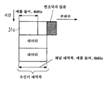
종종, 수신 장치는 수신기가 동조하는 전체 수신 대역폭에 걸쳐 평탄한 주파수 응답을 제공하지 않는다. 게다가, 송신 시스템은 일반적으로 수신 대역폭 윈도우의 경계에서 증가하는 감쇠에 직면한다. 도 6은 통상적인 필터 형상 예의 개략적인 표현을 도시한다. 필터가 사각형이 아니므로, 예를 들면, 8㎒ 대역폭 대신 에, 수신 장치는 사실상 7.61㎒ 대역폭만을 수신할 수 있음을 알 수 있다. 그 결과, 시그널링 패턴들(31)이 동일한 길이를 갖고 수신 장치(83)의 수신 대역폭과 동일한 대역폭을 가져 일부 신호를 잃어 수신 대역폭의 경계에서 일부 신호를 수신할 수 없는 경우, 도 5와 관련하여 기술한 바와 같이 수신 장치(83)는 시그널링 데이터의 재배열을 행할 수 없을 수 있다. 이 문제 및 기타 문제를 극복하기 위해 그리고 수신 장치(83)가 본래의 시퀀스에서 하나의 완전한 시그널링 패턴을 항상 수신할 수 있어 수신된 시그널링 신호를 재배열 또는 재배치할 필요가 없도록 보장하기 위해, 본 발명은 대안으로 또는 추가로 수신기 대역폭에 비해 길이가 감소된 시그널링 패턴(31a)을 사용하는 것을 제안한다.Often, the receiving device does not provide a flat frequency response over the entire receive bandwidth that the receiver tunes. In addition, the transmission system generally faces increasing attenuation at the boundaries of the receive bandwidth window. Figure 6 shows a schematic representation of a typical filter configuration example. Since the filter is not a square, for example, it can be seen that instead of the 8 MHz bandwidth, the receiving device can actually receive only 7.61 MHz bandwidth. As a result, if the signaling
도 7에 도시된 예에 따르면, 수신기 대역폭의 1/2의 길이를 갖지만 여전히 동일한 주파수 구조를 갖는 시그널링 패턴(31a)을 사용하는 것이 제안되어 있다. 다시 말하면, 각 2개의(즉, 쌍의) 1/2 길이의 시그널링 패턴(31a)이 수신기 대역폭과 매칭되고 정렬된다. 이에 의해, 시그널링 패턴(31a)의 각 쌍은 동일한 제1 시그널링 데이터를 가지거나 또는 각 프레임의 시그널링 패턴(31a)의 (변하는) 위치를 포함하는 거의 동일한 제1 시그널링 데이터를 가질 것이다. 그러나, 시그널링 패턴의 나머지 쌍들에 관련하여서는, 이들 나머지 쌍들에서, 이것들은 프레임 내에서 각각 상이한 위치를 가지기 때문에, 시그널링 데이터는 위치 정보를 제외하고 동일할 것이다. 8㎒의 대역폭 또는 길이를 갖는 수신 장치(83)의 상술한 예에서, 시그널링 패턴(31a)은 각각 4㎒의 길이 또는 대역폭을 가질 것이다. 이에 의해, 이전과 동일한 양의 제1 시그널링 데이터가 송신될 수 있음을 보장하기 위해, 시그널링 패턴(31a) 다음의 그리고 데이터 패턴(32, 34, 35, 36, 37) 이전의 시간 슬롯에 추가의 1/2 길이의 시그널링 패턴(31b)을 삽입할 필요가 있다. 이 추가의 시그널링 패턴(31b)은 시그널링 패턴(31a)과 동일한 시간 및 주파수 배열/정렬을 가질 것이지만, 시그널링 패턴(31a)에 포함된 시그널링 정보와는 상이하며 추가인 시그널링 정보를 포함한다. 이러한 방식으로, 수신 장치(83)는 시그널링 패턴(31a 및 31b)을 완전히 수신할 수 있을 것이며, 수신 장치의 재구성 수단(71)은 이 시그널링 패턴(31a 및 31b)의 제1 시그널링 데이터를 본래의 시퀀스에 조합하도록 적응된다. 이 경우, 수신 장치(83)에서의 재구성 수단(71)은 생략될 수 있다. 또한, 유리하게도, 모든 필요한 제1 시그널링 데이터가 1/2 길이로 송신될 수 있고 추가의 시그널링 패턴(31b)이 필요하지 않을 경우, 1/2 길이의 시그널링 패턴(31a)을 갖는 하나의 시간 슬롯만을 제공하는 것도 가능하다. 이 경우, 각 시그널링 패턴(31a)은 동일한(또는 거의 동일한) 제1 시그널링 데이터를 포함하고, 각 수신된 시그널링 패턴(31a)은, 수신 장치(83)가 항상 송신 대역폭의 임의의 원하는 부분에 동조하고 송신 대역폭의 임의의 원하는 부분 따라서 원하는 데이터 패턴을 수신하는 것을 가능하게 한다. 대안으로, 시그널링 패턴(31b) 이후에 연속되는 시간 슬롯에서 더 많은 1/2 길이 시그널링 패턴이 사용될 수 있다.According to the example shown in Fig. 7, it is proposed to use a
일반적으로 (본 발명의 모든 실시예에 대해) 데이터 패턴 및/또는 시그널링 패턴의 길이(또는 대역폭)가, 수신 장치(83)의 유효 수신 대역폭, 예를 들면, 상술한 바와 같이 수신하는 대역 통과 필터의 출력 대역폭에 구성될 수 있음, 예를 들면, 유효 수신 대역폭보다 작을 수 있거나 또는 최대한 이와 동일할 수 있음을 유 의하라.In general, the length (or bandwidth) of the data pattern and / or signaling pattern (for all embodiments of the present invention) depends on the effective receiving bandwidth of the receiving
또한, 본 발명의 모든 실시예에 대해, 하나 이상의 시그널링 패턴(31; 31a, 31b)이, 동일한 길이와 프레임 내에서 동일한 위치를 갖는 하나 이상의 추가 시그널링 패턴에 의해 시간 방향으로 연속된다면 유리할 수 있다. 예를 들면, 프레임의 제1 시그널링 패턴은 다음의 시간 슬롯에서 하나 이상의 추가의 시그널링 패턴을 가질 수 있다. 이에 의해, 추가의 시그널링 패턴은 제1 시그널링 패턴과 동일하거나 또는 거의 동일한 시그널링 정보를 갖는다. 이에 의해, 프레임 내의 다른 시그널링 패턴은 추가의 시그널링 패턴을 가질 필요가 없다. 일반적으로, 프레임 내의 각 주파수 위치에서의 시그널링 패턴의 개수는 달라질 수 있다. 예를 들면, 노치 또는 다른 교란의 관점에서 필요한 많은 시그널링 패턴이 프레임의 각 주파수 위치에서 제공되는 경우에 유리할 수 있다. 대안으로 또는 추가로, 프레임 내의 각 주파수 위치에서의 시그널링 패턴의 개수는 시그널링 데이터의 양에 따라 달라질 수 있다. 이에 의해, 예를 들면, 더 많은 데이터 패턴이 시그널화될 필요가 있을 경우, 더 많은 시그널링 패턴이 시간 방향에서 필요할 것이다. 이에 의해, 시간 방향에서의 시그널링 패턴의 길이는 시그널링 패턴에 포함된 제1 시그널링 데이터의 일부일 수 있다.Also, for all embodiments of the present invention, it may be advantageous if more than one signaling pattern 31 (31a, 31b) is continuous in the time direction by one or more additional signaling patterns having the same length and the same position in the frame. For example, the first signaling pattern of the frame may have one or more additional signaling patterns in the next time slot. Thereby, the additional signaling pattern has the same or substantially the same signaling information as the first signaling pattern. Thereby, other signaling patterns in the frame do not need to have additional signaling patterns. In general, the number of signaling patterns at each frequency location within a frame may vary. For example, it may be advantageous if a number of signaling patterns, which are necessary in terms of notches or other perturbations, are provided at each frequency location of the frame. Alternatively or additionally, the number of signaling patterns at each frequency location within a frame may vary depending on the amount of signaling data. Thus, for example, if more data patterns need to be signaled, more signaling patterns will be needed in the time direction. Thereby, the length of the signaling pattern in the time direction can be a part of the first signaling data included in the signaling pattern.
한정되지 않는 예로서, 제1 시그널링 데이터, 예를 들면, L1(레벨 1) 시그널링 데이터, 부분 주파수 동기화 및 채널 균등화에 사용되는 추가의 파일럿뿐만 아니라 데이터 패턴의 송신 및 수신은 OFDM에 기초한다. 제1 시그널링 데이터는 예를 들면 4㎒의 블록으로 또는 패턴으로 송신되지만, 임의의 기타 적합한 크기도 사 용될 수 있다. 유일하게 필요한 조건은 동조 윈도우 내에 하나의 완전한 시그널링 패턴을 갖는 것이지만, 이 조건은 도 7과 관련하여 기술된 바와 같이 시간 방향으로 서로 연속되는, 더 작은 크기를 갖는 둘 이상의 시그널링 패턴을 이용함으로써 충족될 수 있다. 그러므로, 시그널링 패턴의 최대 대역폭은, 예를 들면, 최신식의 튜너, 즉 7.61㎒의 동조 윈도우일 수 있다. 이하에서 일부 숫자 예가 주어진다. 제1 예에서, 각 시그널링 패턴(31; 31a, 31b)은 정확하게 4㎒를 커버하고, 이것은 448㎲인 OFDM 심볼의 유용한 부분의 지속시간 TU를 갖는 1792 OFDM 주파수 캐리어에 대응한다. 제2 예에서, 각 시그널링 패턴은 7.61㎒(정확하게 3409/448㎲)를 커버하고, 이것은 448㎲인 OFDM 심볼의 유용한 부분의 지속시간 TU를 갖는 3409 OFDM 주파수 캐리어에 대응한다. As a non-limiting example, the transmission and reception of data patterns as well as additional pilots used for first signaling data, e.g., L1 (level 1) signaling data, partial frequency synchronization and channel equalization, is based on OFDM. The first signaling data is transmitted, for example, in blocks of 4 MHz or in a pattern, but any other suitable size may be used. The only requirement is to have one complete signaling pattern in the tuning window, but this condition may be satisfied by using two or more signaling patterns with a smaller size, which are contiguous to each other in the time direction as described in connection with FIG. 7 . Therefore, the maximum bandwidth of the signaling pattern may be, for example, a state of the art tuner, i.e. a tuning window of 7.61 MHz. Some numerical examples are given below. In the first example, each signaling pattern 31 (31a, 31b) covers exactly 4 MHz, which corresponds to a 1792 OFDM frequency carrier with a duration T U of useful portion of the OFDM symbol of 448 占 퐏. In the second example, each signaling pattern covers 7.61 MHz (exactly 3409/448 占 퐏), which corresponds to a 3409 OFDM frequency carrier with duration T U of the useful portion of the OFDM symbol of 448 占 퐏.
제1 양태에 따르면, 파일럿 신호는 도 9에 개략적으로 도시된 바와 같이, 시그널링 패턴(31a)의 매 m번째 주파수 캐리어(17)(m은 1보다 큰 정수)에 매핑된다. 그러나, 이 가능성은 도 4에 도시된 시그널링 패턴(31)에 동일하게 적용되거나, 또는 일반적으로 임의의 적합한 길이의 시그널링 패턴에 적용됨이 명백해야 한다. 주파수 캐리어를 포함하는 파일럿 신호 간의 주파수 캐리어(16)는 시그널링 데이터를 반송하고 있다. 제1 시그널링 데이터를 주파수 캐리어(16)에 매핑하고 파일럿 신호(17)를 매 m번째 주파수 캐리어에 매핑하는 것은 주파수 대 시간 변환 수단(60)에 의해 행해지고, 파일럿과 제1 시그널링 데이터를 시그널링 패턴에 배열하는 것은 도 14에 도시된 바와 같이 송신 장치(82)에 포함된 프레임 형성 수단(59) 에 의해 행해진다. 일반적으로, 상술한 바와 같이, 파일럿 신호는 파일럿 신호 시퀀스를 형성한다. 이에 의해, 파일럿들은, 예를 들면, 차분 변조 방식, 예를 들면, D-BPSK(차분 2진 위상 시프트 키잉)(그러나 이에 한정되지 않음)에 의해 서로에 대해 변조된다. 변조는, 예를 들면, PRBS(의사 랜덤 2진 시퀀스 레지스터, 예를 들면, 2^23-1)에 의해 획득된다. 반복 레이트 m은 도 15에 도시된 바와 같은 본 발명의 수신 장치(83)와 같은 수신 측 상에서 심지어 다중 경로 채널에 대해 명백한 D-BPSK 디코딩을 허용한다. 반복 레이트 m은, 예를 들면, 4㎒ 시그널링 패턴에 대해 7, 14, 28... 인데, 7, 14, 28, ...이 1792(== 4㎒ 시그널링 패턴에서의 주파수 캐리어의 개수)의 분할자(divider)이기 때문이다. 이 예에서, 유리한 반복 값은 m=7이다. 다시 말해, 매 7번째 주파수 캐리어는 인접하는 시그널링 패턴들에 걸쳐 하나의 파일럿 신호를 반송한다. 이 예에서는 4㎒ 시그널링 패턴당 256개의 파일럿 신호가 있다. 그러나, 시그널링 패턴 및/또는 다른 요인의 각 길이에 따라 상술된 예 외의 다른 반복 값이 유리할 수 있다. 본 발명에 따르면, 상술한 바와 같이, 데이터 패턴(들)은 또한 데이터를 갖는 주파수 캐리어들 사이의 주파수 캐리어들 중 일부 상에 매핑된 파일럿 신호를 포함하는데, 이에 의해, 파일럿 신호가 매핑되는 시그널링 패턴의 주파수 캐리어에 대응하는 위치에서의 데이터 패턴의 주파수 캐리어 상에 파일럿 신호가 매핑되는 경우 유리할 수 있다. 일반적으로, 데이터 패턴(들)에서의 파일럿 신호의 밀도는 시그널링 패턴(들)에서의 파일럿 신호의 밀도만큼 높을 필요는 없다. 예를 들면, 파일럿 신호가 시그널링 패턴(들)의 매 m(m은 1보다 큰 정수)번째 주파수 캐리어 상에 매핑되는 경우, 파일럿 신호는 데이터 패턴(들)의 매 n번째 주파수 캐리어 상에 매핑될 수 있다(n은 1보다 큰 정수이며, m의 정수배임). 유리한 예에서와 같이, m=7이면 n=28(또는 임의의 기타 적합한 수)이다. 데이터 패턴(들)에서의 파일럿 신호는 또한 시그널링 패턴(들)에서 설명된 바와 같이 파일럿 신호 시퀀스를 형성할 수 있다.According to a first aspect, the pilot signal is mapped to every m-th frequency carrier 17 (m is an integer greater than 1) of the
시그널링 패턴(들)과 데이터 패턴(들)에 대한 파일럿 신호 시퀀스(예를 들면, PN 시퀀스)의 생성에 관해 2개의 옵션이 있다:There are two options for the generation of a pilot signal sequence (e. G., A PN sequence) for the signaling pattern (s) and the data pattern (s)
·옵션 1 : 각 프레임의 각 시그널링 패턴은 상이한 파일럿 신호 시퀀스를 포함한다. 상술한 예에서, PRBS 레지스터의 초기화는 송신 주파수에 맞춰진다. 256개의 파일럿이 4㎒의 매 주파수 블록 내에 위치된다. 각 4㎒ 블록의 파일럿 신호 시퀀스는 별도로 계산된다. 이것은 수신 측에서의 메모리의 능률적인 구현을 가능하게 한다.Option 1: Each signaling pattern of each frame includes a different sequence of pilot signals. In the above example, the initialization of the PRBS register is tuned to the transmit frequency. 256 pilots are located in every frequency block of 4 MHz. The pilot signal sequence of each 4 MHz block is calculated separately. This enables streamlined implementation of memory at the receiving end.
·옵션 2 : 파일럿 신호 시퀀스는 전체 송신 대역폭에 포함된 모든 시그널링 패턴에 대해 한번 적용된다. 수신기, 예를 들면, 수신 장치(83)는 이 공지된 시퀀스를, 예를 들면, 정수 주파수 오프셋 검출 수단(74)의 일부일 수도 있고 또는 그 외부에 있을 수도 있는 저장 수단에 저장하고, 현재의 동조 위치에 대응하는 주파수 블록을 추출한다.Option 2: The pilot signal sequence is applied once for all signaling patterns included in the total transmission bandwidth. The receiver, for example, the receiving
시그널링 패턴 내의 다른 모든 캐리어(16)는 L1 시그널링 데이터의 송신에 사용된다. 각 시그널링 패턴 내의 시그널링 데이터의 시작은 항상 4㎒ 구조에 맞춰지고, 즉 이것은 항상 도시된 예에서 4㎒의 배수에서 시작된다. 각 4㎒ 시그널링 패턴은 정확하게 동일한 정보를 포함할 수 있는데, 파일럿 신호 시퀀스들 또는 파일럿 신호 시퀀스가 각 프레임의 각각의 시그널링 패턴의 위치에 관한 정보를 수신 장치(83)에 주기 때문이다. 대안으로, 각 시그널링 패턴은 시그널링 패턴의 위치를 프레임에 추가로 포함할 수 있다. 또한, 출력 시간 영역 신호의 피크 대 평균 전원 비를 감소시키기 위해, 각 시그널링 패턴의 시그널링 데이터는, 시그널링 패턴 번호에 의해 획득될 수 있는 고유의 스크램블링 시퀀스에 의해 송신기에서 스크램블될 수 있다.All
수신 장치(83)에서, 시그널링 패턴(31; 31a, 31b)에 포함된 파일럿 신호는 (시간 대 주파수 변환 수단(68)에서, 수신된 시간 영역 심볼의 시간 대 주파수 변환 후에) 정수 주파수 오프셋을 검출하기 위해 정수 주파수 오프셋 검출 수단(74)에서 사용되며, 이후 그 결과는 주파수 영역에서 정수 주파수 오프셋 보상을 행하기 위해 수신 장치(83)에서 사용된다. 보다 구체적으로, 수신된 주파수 범위 내의 시그널링 패턴에 포함된 (예를 들면, D-BPSK 변조된) 파일럿 신호는 정수 주파수 오프셋 검출 수단(74)에 포함된 복조 수단(75)에서 복조된다. 이후, 정수 주파수 오프셋 검출 수단(74)에 포함된 상관 수단(76)은, 정확한 주파수 오프셋에 맞추기 위해 복조된 파일럿 신호(파일럿 신호 시퀀스)와 저장되거나 생성된(예상되는) 파일럿 신호 시퀀스, 예를 들면, PRBS 시퀀스의 상관을 행한다. 이 상관은 (수신기 측의 테이블에서 리스트될 수 있는) 시그널링 패턴의 시작 부분에서 예상되는 PRBS 시퀀스로 행해진다. 시퀀스가 수신된 심볼 내에서 발견되면, 수신 장치(83)는 정확한 주파수 오프셋을 알아내고 그것을 보상한다. 보다 구체적으로, 이 획득된 정수 주파수 오프셋은, 제1 시그널링 데이터를 올바르게 복조하기 위해 재구성 수 단(71) 및 디-매핑 수단(72)에 공급되어 사용될 수 있을 뿐만 아니라, 채널 추정 그리고 균등화를 행하기 위해 채널 추정 수단(69)에 공급되고 사용될 수 있다. In the
필요한 시간 동기화뿐만 아니라 부분 주파수 오프셋 검출 및 보상은, 예를 들면, 수신된 시그널링 심볼 및/또는 데이터 심볼의 보호 구간을 이용하는 보호 구간 상관을 이용하여 시간 동기화 수단(66) 및 부분 주파수 오프셋 검출 수단(67)에서, 수신된 시간 영역 심볼에 대해 시간 영역에서 행해진다(시그널링 심볼, 데이터 심볼 및 보호 구간을 갖는 프레임의 시간 영역 표현을 도시하는 도 13을 참조하라). 시간 동기화는 대안으로는 수신된 시간 영역 심볼과 파일럿 신호만이 변조되는 수신기 생성된 시간 영역 심볼 간의 절대값의 상관을 행함으로써 행해질 수 있다. 수신된 심볼 및 수신기 생성된 심볼의 상관에서의 피크는 정확한 시간 동기화를 가능하게 한다.Partial frequency offset detection and compensation, as well as the necessary time synchronization, can be performed, for example, by time synchronizing means 66 and partial frequency offset detecting means 66 using guard interval correlation using the guard interval of the received signaling symbols and / 67), which is done in the time domain for the received time domain symbols (see FIG. 13, which shows a time domain representation of the frame with signaling symbols, data symbols and guard intervals). Time synchronization may alternatively be performed by correlating the received time-domain symbols with the absolute values of the receiver-generated time-domain symbols for which only the pilot signal is modulated. The peak in the correlation of the received symbol and the receiver generated symbol enables accurate time synchronization.
도 10에 개략적으로 도시된 제2 양태에 따르면, 각 시그널링 패턴(31a)(또는 시그널링 패턴(31))은 파일럿 대역(18, 19)의 주파수 캐리어(20, 21) 상에 매핑된 파일럿 신호를 포함하는 적어도 하나의 파일럿 대역(18, 19)을 포함한다. 파일럿 대역(18, 19)은 각각 파일럿 신호들이 매핑되는 바로 인접하는 많은 주파수 캐리어를 포함한다. 파일럿 대역(18, 19)은 각각 동일한 개수의 주파수 캐리어 또는 상이한 개수의 주파수 캐리어를 가질 수 있다. 이에 의해, 각 시그널링 패턴(31a)은 (주파수 방향으로) 그 시작 단부 및 그 끝 단부에 파일럿 대역(18, 19)을 포함할 수 있다. 대안으로, 각 시그널링 패턴은 각각의 경계에, 즉 패턴의 시작 및 끝 부분에 파일럿 대역(18, 19)을 포함할 수 있다. 옵션 1 및 옵션 2을 포함하여, 본 발명의 제1 양태에 관련하여 위에서 행해진 모든 기타의 기술 및 정의도 제2 양태에 또한 적용된다. 제1 및 제2 양태가 조합될 수도 있음, 즉 각 시그널링 패턴이 상술한 바와 같이 적어도 하나의 파일럿 대역(18, 19)뿐만 아니라 매 m번째 주파수 캐리어(12)에 매핑된 파일럿 신호를 포함할 수 있음을 이해할 것이다.10, each
상술한 본 발명의 두 가지 모두의 양태에서, 파일럿 신호를 갖는 주파수 캐리어의 개수와 각 시그널링 패턴 내의 제1 시그널링 데이터를 갖는 주파수 캐리어의 개수간의 관계는 변할 수 있고 각 시그널링 및 오프셋 보상 요건에 종속된다.In both embodiments of the invention described above, the relationship between the number of frequency carriers with pilot signal and the number of frequency carriers with first signaling data in each signaling pattern may vary and is dependent on each signaling and offset compensation requirement .
도 11에 개략적으로 도시된 바와 같이, 송신 장치(82)는 케이블 네트워크에서 다른 서비스로, 예를 들면, 항공기 무선으로의 교란을 피하기 위해, 전체 송신 대역폭의 일부 구역(22, 23)을 비울 수 있다(노치). 그러므로, 스펙트럼의 일부분은 변조되지 않을 수 있다. 이 경우, 시그널링 패턴(31; 31a, 31b) 내의 영향을 받는 주파수 캐리어 또한 변조되지 않을 것이다. 본 발명에 의해 제안되는 동기화가 매우 강하기 때문에, 이것은 D-BPSK 변조된 파일럿에 의한 주파수 동기화 성능에 영향을 끼치지 않는다. 제1 시그널링 데이터의 잃어버린 부분은, 제1 시그널링 데이터의 반복(프레임의 각 시그널링 패턴(31; 31a, 31b)은 동일하거나 거의 동일한 제1 시그널링 데이터를 포함함)에 의해, 예를 들면, 도 11에 도시된 바와 같은 2개의 인접하는 시그널링 패턴으로부터의 부분들을 조합함으로써, 그리고 결국에는 송신 장치(82)에 포함된 에러 코딩 수단(56)에 의해 시그널링 패턴에 추가된 강한 에러 방지에 의해 회복된다. 송신 대역폭의 에지에서의 제1 시그널링 데이터의 잃어버린 부분들은 매우 광범위한 노치로서 취급될 것이다.As shown schematically in Figure 11, the transmitting
노치 또는 다른 문제에 대처하는 대안의 가능성 또는 추가의 가능성은, 시그널링 패턴(31; 31a, 31b)을 둘 이상의 부분으로 분할하고 (프레임의) 각 시그널링 패턴의 둘 이상의 부분의 시퀀스를 프레임별로 거꾸로 하는 것이다. 예를 들면, 프레임의 제1 시그널링 패턴이 제1 및 (연속되는) 제2 부분으로 분할되는 경우, 바로 다음 프레임의 (대응하는) 제1 시그널링 패턴에서는 그 시작 부분에는 제2 부분이 있고 제1 시그널링 부분이 연속될 것이다, 즉 거꾸로 된 시퀀스이다. 따라서, 예를 들면 제2 부분이 노치되거나 또는 교란되는 경우, 수신기는 제2 부분이 문제없이 수신될 수 있는 다음 프레임을 기다려야 한다(다음의 제1 부분이 교란될 것이기 때문임). The possibility or the further possibility of an alternative to coping with a notch or other problem is that the signaling pattern 31 (31a, 31b) is divided into two or more parts and the sequence of two or more parts of each signaling pattern (of the frame) will be. For example, when the first signaling pattern of a frame is divided into first and (contiguous) second portions, the first (corresponding) first signaling pattern of the immediately following frame has a second portion at the beginning thereof, The signaling portion will be continuous, i. E., An inverted sequence. Thus, for example, if the second portion is notched or disturbed, the receiver has to wait for the next frame in which the second portion can be received without problems (because the next first portion will be disturbed).
시그널링 패턴(31; 31a, 31b)을 수신 측의 상이한 동조 대역폭에 적응시키는 것은, 예를 들면, 시그널링 패턴에서의 주파수 캐리어들의 거리를 변경시킴으로써 행해질 수 있다. 대안으로는, 주파수 캐리어의 거리를 일정하게 유지하고, 예를 들면, 도 12에 개략적으로 도시된 바와 같이, 각각의 주파수 캐리어를 변조시키지 않음으로써 송신 대역폭의 에지에서 시그널링 패턴의 일부를 자르는 것이 가능하며, 도 12에서는 4㎒ 시그널링 패턴을 갖는 방식을 6㎒ 동조 대역폭에 적응시켜 최대 6㎒ 길이를 갖는 데이터 패턴의 수신을 가능하게 하는 것을 도시한다.Adaptation of the signaling pattern 31 (31a, 31b) to the different tuning bandwidth of the receiving side can be done, for example, by changing the distance of the frequency carriers in the signaling pattern. Alternatively, it is possible to keep a distance of the frequency carrier constant and to cut off a portion of the signaling pattern at the edge of the transmission bandwidth, for example, by not modulating each frequency carrier, as schematically shown in Figure 12 In FIG. 12, a scheme having a 4 MHz signaling pattern is adapted to a 6 MHz tuning bandwidth to enable reception of a data pattern having a maximum length of 6 MHz.
결국에는, 각 시그널링 패턴(31; 31a, 31b)은 각 패턴의 시작과 끝 부분에 보호 대역을 추가로 포함한다. 대안으로, 일부 응용에서, 각 프레임의 제1 시그널링 패턴, 예를 들면 도 4의 예에서 위치(39)에서의 시그널링 패턴이 패턴의 시작부분에서만 보호 대역을 포함하고, 각 프레임의 마지막 시그널링 패턴은 그 패턴의 끝 부분에서만 보호 대역을 포함한다면 유리할 수 있다. 대안으로, 일부 응용에서, 각 프레임의 제1 시그널링 패턴만이, 도 4의 예에서 위치(39)에서의 시그널링 패턴만이 그 시작 부분뿐만 아니라 끝 부분에 보호 대역을 포함할 수 있고, 각 프레임의 마지막 시그널링 패턴은 패턴의 시작 부분뿐만 아니라 끝 부분에 보호 대역을 포함할 것이다. 일부 또는 모든 시그널링 패턴에 포함된 보호 대역의 길이는, 예를 들면, 수신 장치가 대처할 수 있는 최대 주파수 오프셋보다 작거나 최대로 이와 같을 것이다. 수신기 대역폭이 8㎒인 언급된 예에서, 보호 대역은, 예를 들면, 그 길이가 250 내지 500㎑일 수 있고 또는 임의의 기타 적합한 길이일 수 있다. 또한, 시그널링 패턴에 포함된 각 보호 대역의 길이는, 적어도, 도 6과 관련하여 기술한 필터 특성으로 인해, 수신 장치에서 수신되지 않은 캐리어들의 길이일 수 있다. 예를 들면, 전체 송신 대역폭이 8㎒의 배수(4nk 모드;k는 1024 캐리어/샘플의 푸리에 윈도우 크기이며, n=1,2,3,4... 임)이고 각 시그널링 패턴의 길이가 4㎒인 OFDM 시스템에서, 각 시그널링 패턴의 시작 및 끝 부분에서의 각 보호 대역의 길이에 대한 제안은 343개(이것은 각 4nk 모드의 각 프레임의 시작 및 끝 부분에서의 데이터 패턴에서 사용되지 않는 캐리어의 개수임)의 주파수 캐리어일 것이다. 그 결과, 각 시그널링 패턴에서 사용가능한 캐리어의 개수는 3584/2-2×343=1106개의 캐리어일 것이다. 그러나, 이 수는 단지 예로서 사용된 것이며, 어떤 의미에서도 한정하는 것을 의미하지 않음을 이해할 것이다. 이에 의해, 시그널링 패턴에 포함된 각 보호 대역의 길이는 적어도, 도 6과 관련하여 기술된 필터 특징으로 인해 수신 장치에서 수신되지 않은 캐리어의 길이일 것이므로, 각 시그널링 패턴에서의 시그널링 데이터의 길이는 유효 수신기 대역폭과 동일하다(또는 이보다 작을 수 있다). 추가의 시그널링 패턴(31b)이 존재한다면, 그것은 시그널링 패턴(31a)과 동일한 보호 대역을 가질 것임을 유의하라. 추가로 또는 대안으로, 각 데이터 패턴은 각 패턴의 시작 및 끝 부분에 사용되지 않은 캐리어를 갖는 보호 대역을 포함할 수 있다. 대안으로, 일부 응용에서, 주파수 방향으로 각 프레임의 각각의 제1 데이터 패턴만이, 도 10 및 도 13의 예에서는 데이터 패턴(32, 32', 32'', 32''', 32'''')만이 데이터 패턴의 시작 부분에서만 보호 대역을 포함할 수 있고, 주파수 방향으로 각 프레임의 마지막 데이터 패턴이, 도 4 및 도 7의 예에서는 데이터 패턴(37, 37', 37'', 37''', 37'''')이 데이터 패턴의 끝 부분에서 보호 대역을 포함할 수 있다. 이에 의해, 데이터 패턴의 보호 대역의 길이는, 예를 들면, 시그널링 패턴이 보호 대역을 포함한다면 시그널링 패턴의 보호 대역들의 길이와 동일할 수 있다.Eventually, each signaling pattern 31 (31a, 31b) additionally includes a guard band at the beginning and end of each pattern. Alternatively, in some applications, the first signaling pattern of each frame, e.g., the signaling pattern at
상술한 바와 같이, 시그널링 패턴(31, 31a 및/또는 31b)(또는 본 발명에 따른 다른 시그널링 패턴)에 포함된 제1 시그널링 데이터는 물리 층 정보를 포함하며, 이것은 본 발명에 따른 수신 장치(83)가 프레임 구조에 관한 지식을 획득하고 원하는 데이터 패턴을 디코딩하는 것을 가능하게 한다. 한정하지 않는 예로서, 제1 시그널링 데이터는 전부 또는 전체 송신 대역폭, 프레임 내에서의 각 시그널링 패턴의 위치, 시그널링 패턴에 대한 보호 대역 길이, 데이터 패턴에 대한 보호 대역 길이, 수퍼 프레임을 만드는 프레임의 개수, 수퍼 프레임 내에서의 본 프레임의 번호, 전체 프레임 대역폭의 주파수 차원에서의 데이터 패턴의 개수, 프레임의 시간 차원에서의 추가의 데이터 패턴의 개수 및/또는 각 프레임의 각 데이터 패턴에 대한 개개의 시그널링 데이터의 개수와 같은 파라미터들을 포함할 수 있다. 이에 의해, 프레임 내에서의 각 시그널링 패턴의 위치는, 예를 들면, 전체 대역폭의 분할과 관련하여 시그널링 패턴의 위치를 나타낼 수 있다. 예를 들면, 도 4의 예에서, 제1 시그널링 데이터는 시그널링 패턴이 제1 세그먼트(예를 들면, 제1의 8㎒ 세그먼트)에 위치하는지, 또는 제2 세그먼트 등에 위치하는지에 대한 표시를 포함한다. 예를 들면, 도 7과 관련하여 설명한 바와 같이, 시그널링 패턴이 대역폭 분할의 1/2 길이를 가지면, 각 쌍의 인접하는 시그널링 패턴은 동일한 위치 정보를 가진다. 어떤 경우에서든지, 수신 장치는 이 위치 정보를 이용하여 다음의 프레임에서 원하는 주파수 대역에 동조할 수 있을 것이다. 개별의 (제1) 시그널링 데이터는 프레임에 존재하는 각 데이터 패턴에 개별적으로 제공되는 별도의 데이터 블록이며, 데이터 패턴의 제1 주파수 캐리어, 데이터 패턴에 배치된 주파수 캐리어의 개수(또는 주파수 방향으로 최소 데이터 패턴 길이의 배수에 의한 데이터 패턴의 길이), 데이터 패턴용 시간 인터리버의 사용, 데이터 패턴에서의 주파수 노치(데이터 패턴에서 데이터 송신에 사용되지 않는 주파수 캐리어)의 개수, 주파수 노치의 위치 및/또는 주파수 노치의 폭 등과 같은 파라미터를 포함할 수 있다. 송신 상치(82)의 프레임 형성 수단(59)은 대응하는 제1 시그널링 데이터를 각 시그널링 패턴에 배열하도록 구성된다. 수신 장치(83)의 평가 수단(73)은 수신된 시그널링 데이터를 평가하고, 수신 장치(83) 내에서의 추가의 처리를 위해 제1 시그널링 데이터에 포함된 정보를 사용하거나 또는 이를 전달하도록 구성된다. 제1 시그널링 데이터가 프레임에 존재하는 각 데이터 패턴에 대해 언급된 개별 시그널링 정보를 포 함하는 경우, 시그널링 패턴의 구조는 각 시그널링 패턴의 크기를 최대 크기로 제한하기 위해, 프레임당 주파수 방향에서의 데이터 패턴의 최대 제한 개수를 지원한다. 따라서, 각 프레임의 주파수 방향에서의 데이터 패턴의 개수가 동적으로 그리고 유연하게 변경될 수 있지만, 이것은 소정의 최대 개수의 데이터 패턴 내에서만 그럴 것이다. 각 프레임의 시간 방향에서의 추가의 데이터 패턴은 상술한 바와 같이, 앞선 데이터 패턴에 각각 맞춰진다. 따라서, 각각의 추가의 다음의 데이터 패턴은 이전 데이터 패턴과 동일한 위치, 길이, 변조 등을 가지며, 이전 데이터 패턴에 대한 시그널링 데이터는 또한 다음의 데이터 패턴에 대해 유효하다. 이에 의해, 각 프레임의 시간 방향에서의 추가의 데이터 패턴의 개수는 고정적이거나 또는 가변적일 수 있으며, 이 정보는 또한 시그널링 데이터에 포함될 수 있다. 마찬가지로, 시그널링 패턴의 구조는 각 데이터 패턴에서 주파수 노치의 최대 제한 개수만을 지원할 수 있다.As described above, the first signaling data included in the
대안으로 또는 추가로, 시그널링 패턴(31)의 일부가 수신 장치(83)에서 수신될 수 없다는 문제점을 극복하기 위해, 송신 장치(82)는 변조 수단(55) 앞에 배치되고 제1 시그널링 데이터에 반복 코딩, 순환 리던던시 코딩 등과 같은 소정의 종류의 에러 코딩, 리던던시를 추가하도록 구성된 에러 코딩 수단(56)을 선택적으로 포함할 수 있다. 이 추가의 에러 코딩은 도 4에 도시된 바와 같이 송신 장치(82)가 훈련 패턴(30)과 동일한 길이의 시그널링 패턴(31)을 사용하는 것을 가능하게 하는데, 이는 수신 장치(83)가, 예를 들면, 재구성 수단(71)에 의해 본래의 시그널링 패턴을 재구성하기 위해 소정의 종류의 에러 검출 및/또는 정정을 행할 수 있기 때문이다.Alternatively or additionally, in order to overcome the problem that a part of the
4㎒의 길이를 가지며 OFDM 시스템에서 8㎒의 세그먼트에 맞춰진 시그널링 패턴의 언급된 예에 대해, 시그널링 구조의 이하의 특정(한정되지 않는) 예를 기술한다. 448㎲의 OFDM 심볼 지속시간의 경우, 각 4㎒ 블록은 1792 OFDM 서브캐리어에 의해 만들어진다. 주파수 영역 파일럿이 시그널링 심볼 내의 매 7번째 OFDM 캐리어에서 사용되는 경우, 1536 OFDM 캐리어가 각 시그널링 OFDM 심볼 내의 L1 시그널링 데이터의 송신용으로 남겨진다. 이 OFDM 캐리어는, 예를 들면, 16 QAM에 의해 변조될 수 있으며, 그 결과 일반적으로 L1 시그널링 내에 6144개의 송신가능한 비트가 생긴다. 송신가능한 비트 중 일부는 에러 정정용으로, 예를 들면, LDPC 또는 리드 솔로몬 코드(Reed Solomon code)에 사용되어야 한다. 이후 나머지 최종 비트들은 이하의 테이블에 기술한 바와 같이 시그널링을 위해 사용된다.For the mentioned example of a signaling pattern with a length of 4 MHz and adapted to an 8 MHz segment in an OFDM system, the following specific (non-limiting) example of the signaling structure is described. For an OFDM symbol duration of 448 ㎲, each 4 ㎒ block is made by 1792 OFDM subcarriers. If a frequency domain pilot is used in every seventh OFDM carrier within the signaling symbol, 1536 OFDM carriers are left for transmission of the L1 signaling data in each signaling OFDM symbol. This OFDM carrier can be modulated, for example by 16 QAM, resulting in 6144 transmittable bits in the L1 signaling in general. Some of the transmittable bits should be used for error correction, for example in LDPC or Reed Solomon codes. The remaining remaining bits are then used for signaling as described in the table below.
이하에서, 상기 테이블에서 언급된 시그널링 데이터의 파라미터들을 더 상세 하게 설명한다:In the following, the parameters of the signaling data mentioned in the table are explained in more detail:
GI 길이 : 사용된 보호 구간의 길이를 정의함GI Length: Defines the length of the used guard interval.
프레임 번호 : 각 프레임, 즉 각 시그널링 심볼마다 증가되는 카운터 Frame number: Each frame, that is, a counter that is incremented for each signaling symbol
총 대역폭 : 사용된 채널의 전체 송신 대역폭Total bandwidth: Total transmission bandwidth of the used channel
데이터 슬라이스의 총 개수 : 이 파라미터는, 사용된 채널에서의 데이터 슬라이스, 즉 데이터 패턴의 총 개수를 시그널링함Total number of data slices: This parameter signals the total number of data slices, or data patterns, in the channel used
L1 서브-시그널링 테이블 번호 : 시그널링 데이터 내의 서브-시그널링 테이블의 번호L1 sub-signaling table number: the number of the sub-signaling table in the signaling data
서브-테이블된 데이터 슬라이스의 개수 : 이 L1 시그널링 테이블 내에서 시그널화된 데이터 슬라이스의 개수Number of sub-table data slices: Number of signaled data slices in this L1 signaling table
데이터 슬라이스 번호 : 현재 데이터 슬라이스의 번호Data slice number: the number of the current data slice
시작 서브캐리어 주파수 : 데이터 슬라이스의 시작 주파수Start subcarrier frequency: Starting frequency of the data slice
슬라이스당 서브캐리어의 개수 : 데이터 슬라이스당 서브캐리어의 개수Number of subcarriers per slice: Number of subcarriers per data slice
시간 인터리빙 깊이 : 현재 데이터 슬라이스 내에서의 시간 인터리빙 깊이Time interleaving depth: The time interleaving depth in the current data slice
PSI/SI 재처리 : 현재의 데이터 슬라이스에 대해 PSI/SI 재처리가 송신기에서 행해졌는지를 시그널화함PSI / SI reprocessing: signaling whether the PSI / SI reprocessing has been done at the transmitter for the current data slice
노치의 개수 : 현재 데이터 슬라이스 내에서의 노치의 개수Number of notches: Number of notches in the current data slice
슬라이스의 시작에 대한 노치의 시작 : 데이터 슬라이스의 시작 주파수에 대한 데이터 슬라이스 내에서의 노치의 시작 위치Start of notch for start of slice: Starting position of notch in data slice for starting frequency of data slice
노치 폭 : 노치의 폭Notch Width: Notch Width
예비 비트 : 앞으로의 사용을 위한 예비 비트Spare bits: spare bits for future use
CRC_32 : L1 시그널링 블록에 대한 32비트 CRC 코딩CRC_32: 32-bit CRC coding for L1 signaling block
수신 장치(83)에서의 시그널링 패턴의 더 나은 수신을 보장하기 위해, 본 발명은 수신 장치(83)의 동조 위치를 최적화하는 것을 더 제안한다. 도 4 및 도 7에 도시된 예에서, 수신기는 수신될 데이터 패턴의 주파수 대역폭 주위에서 부분(38)을 중심에 둠으로써 송신 대역폭의 부분(38)에 동조한다. 대안으로는, 수신 장치(83)는, 시그널링 패턴(31)의 최대 부분이 수신되면서 원하는 데이터 패턴도 여전히 완전히 수신되도록 부분(38)을 배치함으로써 시그널링 패턴(31)의 수신이 최적화되도록 동조할 수 있다. 대안으로는, 각 데이터 패턴의 길이는 각 시그널링 패턴(31)의 길이와 소정의 백분율, 예를 들면, 10% 이상 다르게 할 수 없다. 이 해결책에 대한 예는 도 8에 있다. 데이터 패턴들(42, 43, 44, 45) 간의 경계는, 시그널링 패턴들(31) 간의 경계에서 (주파수 방향으로) 10%와 같은 (그러나 이에 한정되지 않음) 소정의 백분율 이상 벗어나지 않는다. 이후 이 작은 백분율은 상술된 시그널링 패턴(31)에서의 추가의 에러 코딩에 의해 보정될 수 있다.To ensure better reception of the signaling pattern at the receiving
도 13은 본 발명에 따른 프레임(47)의 예의 시간 영역 표현을 도시한다. 송신 장치(82)에서, 프레임 패턴 또는 구조가 프레임 형성 수단(59)에서 생성된 후, 주파수 대 시간 변환 수단(60)에 의해 주파수 영역 프레임 패턴은 시간 영역으로 변환된다. 그 결과 생긴 시간 영역 프레임의 예가 이제 도 13에 도시되어 있으며, 이것은 보호 구간(49), 시그널링 심볼(50), 추가의 보호 구간(51) 및, 각각 보호 구간(53)에 의해 분리되어 있는 많은 데이터 심볼(52)을 포함한다. 단일의 시그널 링 심볼만이 시간 영역에 존재하는 상황은, 시그널링 패턴을 갖는 단일의 시간 슬롯만이 주파수 영역 프레임 구조에 존재하는 도 4에 도시된 예에 대응하는 반면, 시그널링 패턴(31a 및 31b)을 각각 갖는 2개의 시간 슬롯을 갖는 도 7의 예에서는 결국 보호 구간에 의해 분리되는 시간 영역 내에 2개의 시그널링 패턴이 존재하게 된다. 보호 구간은, 예를 들면, 각 심볼의 유용한 부분의 순환적인 확장부일 수 있다. OFDM 시스템의 예에서, 마침내 제공되는 보호 대역을 비롯한 시그널링 심볼 및 데이터 심볼은 각각 하나의 OFDM 심볼의 길이를 가질 수 있다. 이후 이 시간 영역 프레임은, 사용된 멀티-캐리어의 시스템에 따라, 예를 들면, 신호를 원하는 송신 주파수로 업 컨버팅함으로써 시간 영역 신호를 처리하는 송신 수단(61)으로 전달된다. 이후 송신 신호는, 안테나 등과 같은 유선 인터페이스 또는 무선 인터페이스일 수 있는 송신 인터페이스(62)를 통해 송신된다. 상술한 바와 같이, 하나 이상의 훈련 패턴이 시그널링 패턴(들)을 앞설 수 있으며, 그리하여 시간 영역에서 시그널링 심볼을 앞서는 훈련 심볼이 존재하게 된다.Figure 13 shows a time domain representation of an example of a
도 13은 각각의 많은 프레임들이 수퍼 프레임으로 조합될 수 있음을 또한 도시한다. 수퍼 프레임당 프레임의 개수, 즉 시간 방향에서의 각 수퍼 프레임의 길이는 고정적일 수도 있고 또는 변할 수도 있다. 이에 의해, 수퍼 프레임이 동적으로 설정될 수 있는 최대 길이가 있을 수 있다. 또한, 수퍼 프레임에서 각 프레임에 대한 시그널링 패턴의 시그널링 데이터가 동일하다면, 그리고 시그널링 데이터에서의 변경이 수퍼 프레임에서부터 수퍼 프레임으로만 발생한다면 유리할 수 있다. 다시 말하면, 데이터 패턴의 변조, 코딩, 개수 등은 수퍼 프레임의 각 프레임 에서 동일할 것이지만, 연속하는 수퍼 프레임에서는 다를 수 있다. 예를 들면, 방송 시스템에서 수퍼 프레임의 길이는 시그널링 데이터가 자주 변경하지 않을 것이기 때문에 더 길 수 있으며, 인터랙티브 시스템에서 슈퍼 프레임의 길이는 송신 및 수신 파라미터의 최적화가 수신기에서 송신기로의 피드백에 기초하여 행해질 수 있기 때문에 더 짧을 수 있다. 언급한 바와 같이, 각 프레임에서 훈련 심볼은 각 시그널링 심볼에 앞설 수 있다.Figure 13 also shows that each of many frames can be combined into a superframe. The number of frames per superframe, i.e., the length of each superframe in the temporal direction, may be fixed or may vary. Thereby, there may be a maximum length at which the superframe can be set dynamically. It may also be advantageous if the signaling data of the signaling pattern for each frame in the superframe is the same and if the change in the signaling data occurs only from the superframe to the superframe. In other words, the modulation, coding, and number of data patterns will be the same in each frame of a superframe, but may differ in successive superframes. For example, the length of a superframe in a broadcast system may be longer because the signaling data will not change often, and in an interactive system the length of a superframe is such that optimization of transmit and receive parameters is based on feedback from the receiver to the transmitter It can be shorter because it can be done. As mentioned, training symbols in each frame may precede each signaling symbol.
송신 장치(82)의 구성 요소 및 기능은 도 14에 도시된 블록도에서 앞서 설명되었다. 송신 장치(82)의 실제 구현이 각 시스템에서의 송신 장치의 실제 동작에 필요한 추가의 구성 요소와 기능성을 포함할 것임을 이해할 것이다. 도 14에서는, 본 발명을 설명하고 이해하는 데에 필요한 구성 요소와 수단만이 도시되어 있다. 수신 장치(83)에 대해서도 마찬가지인데, 도 15에 도시된 블록도는 본 발명을 이해하는 데에 필요한 구성 요소와 기능만을 도시한다. 추가의 구성 요소들이 수신 장치(83)의 실제 동작을 위해 필요할 것이다. 또한, 송신 장치(82)뿐만 아니라 수신 장치(83)의 구성 요소 및 기능이 임의의 종류의 디바이스, 장치, 시스템 등에서 구현되어 본 발명에 의해 설명되고 청구되는 기능을 행하도록 구성될 수 있음을 이해할 것이다.The components and functions of the transmitting
상술한 바와 같이, 도 4 및 도 7에 각각 도시된 프레임 구조(29, 29')를 갖는 프레임 내의 데이터 패턴과 같은 본 발명의 데이터 패턴 내의 데이터는 데이터 프레임에 배열되며, 각 데이터 프레임은 제2 시그널링 데이터와 콘텐츠 데이터를 포함한다. 이에 의해 제2 시그널링 데이터는 각 데이터 프레임의 콘텐츠 데이터의 개별 파라미터를 갖는 시그널링 데이터이며, 예를 들면 데이터 프레임의 콘텐츠 데이터에서 사용되는 변조, 데이터 프레임의 콘텐츠 데이터에서 사용되는 에러 방지 코드, 콘텐츠 데이터 및 데이터 프레임이 수신 장치에 의도되는 것인지에 관한 수신 장치에 대한 정보를 갖는 접속 ID와 같으나 이에 한정되지 않는다.As described above, data in the data patterns of the present invention, such as data patterns in frames having
도 17에 도시된 바와 같이, 본 발명의 데이터 프레임(84)은 헤더(84a)에 제2 시그널링 데이터를 포함할 수 있고, (시간 방향으로) 이에 이어서 콘텐츠 데이터(84b)가 있다. 즉, 도 17은 도 14에 도시된 송신 장치(82)의 데이터 프레임 형성 수단(54, 54', 54'')에 의해 형성된 본 발명의 데이터 프레임(84)을 도시한다.As shown in FIG. 17, the
도 18은, 도 4 및 도 7에 각각 도시된 프레임 구조(29, 29')를 갖는 프레임의 데이터 패턴(34, 34', 34'', 34''', 34'''')과 같은, 동일한 주파수 배치를 갖고 시간 차원으로 인접하는 데이터 패턴에 여러 데이터 프레임이 어떻게 배치되고 삽입되는지를 개략적으로 도시한다. 도 18에 도시된 바와 같이, 각 상이한 길이의 (및/또는 상이한 데이터 및/또는 시그널링 콘텐츠 및/또는 상이한 변조 및/또는 상이한 코딩의) 여러 데이터 프레임들(85, 85', 85'', 85''')은 완전히 독립적이고 유연한 방식으로 데이터 패턴(34, 34', 34'', 34''', 34'''')에 배치되어 있다. 다시 말하면, 데이터 프레임(85, 85', 85'', 85''')의 길이(주파수 캐리어의 개수)는, 데이터 패턴(34, 34', 34'', 34''', 34'''')의 길이(주파수 캐리어의 개수)와 완전히 무관하며, 데이터 프레임(85, 85', 85'', 85''')은 데이터 패턴(34, 34', 34'', 34''', 34'''')에서 서로 연속하여 배치되어 있다. 따라서, 데이터 프레임의 구조는 일반적으로 전체적인 프레임 구조(예를 들면, 프레임 구조(29, 29')를 갖는 프레임)와 완전히 무관하다. 그러나, 주파수 구조, 즉 데이터 패턴(34, 34', 34'', 34''', 34'''')의 제1 주파수 캐리어와 최종 주파수 캐리어는 또한 데이터 프레임(85, 85', 85'', 85''')의 주파수 구조이다. 동일한 주파수 배치를 갖고 시간 차원으로 서로 인접하는 데이터 패턴들이 데이터 프레임용의 일종의 컨테이너를 형성하며, 데이터 프레임은 컨테이너 안으로 완전히 자유롭게 그리고 독립적으로 삽입될 수 있다. 도 18이 명료함을 위해 시간 및/또는 주파수를 인터리빙하지 않고 데이터 프레임(85, 85', 85'', 85''')을 도시함을 유의하라. 실제 구현에서, 데이터 프레임(85, 85', 85'', 85''')은 시간 및/또는 주파수가 인터리빙된 형태로 데이터 패턴(34, 34', 34'', 34''', 34'''')에 삽입될 것이다. Fig. 18 shows an example of the
각 데이터 프레임(85, 85', 85'', 85''')의 각 헤더(85a, 85a', 85a'', 85a''')에 포함된 제2 시그널링 데이터는 각 데이터 프레임에 대해 개별적인 제2 시그널링 데이터를 포함한다. 다시 말해서, 헤더(85a, 85a', 85a'', 85a''')에 포함된 제2 시그널링 데이터는 서로 적어도 부분적으로 상이하다. 각 데이터 프레임(85, 85', 85'', 85''')의 길이는 프레임의 제2 시그널링 데이터에 또는 상술한 제1 시그널링 데이터 둘 중 하나에 시그널링될 수 있다. 상술한 바와 같이, 제2 시그널링 데이터는 각 데이터 프레임의 콘텐츠 데이터의 변조, 각 데이터 프레임 내의 콘텐츠 데이터의 (에러) 코딩 및/또는 접속 ID를 포함할 수 있다. 추가 또는 대안의 시그널링 콘텐츠는 또한 원하는 구현에 따라 또한 제2 시그널링 데이터에 포함될 수도 있다. 예를 들면, 제2 시그널링 데이터는 (암시적으로 또는 명시적으로) 데이터 프레임의 콘텐츠 데이터의 길이에 대한 일부 표시를 포함한다. 일부 구현에서, 변조와 코딩이 동일하다면, 콘텐츠 데이터의 길이 또한 동일하다. 따라서, 연속되는 데이터 프레임 내의 콘텐츠 데이터의 변조와 코딩이 계속 동일한 경우, 이 동일한 변조와 코딩을 (연속되는 데이터 프레임의 헤더에서) 다시 시그널할 필요가 없고 변조 및 코딩이 이전과 계속 동일하다는 것을 나타내기만 하면 된다. 대안으로, 변조 및 코딩이 앞선 데이터 프레임과 관련하여 변경되지 않는 경우, 연속되는 데이터 프레임의 헤더가 생략될 수 있는 구현도 가능할 것이다.The second signaling data contained in each
각 데이터 프레임(85, 85', 85'', 85''')의 제2 시그널링 데이터는 유리하게, 수신 장치(83)의 상관 수단(78)에서 각 헤더(85a, 85a', 85a'', 85a''')의 시작을 검출하기 위해 상관을 행하는 데에 사용되는 의사-잡음 시퀀스 또는 임의의 기타 적합한 시퀀스와 같은 동기화 시퀀스를 포함한다. 심볼 동기화가 이미 일어났기(예를 들면, 멀티-캐리어 복조에 의해 달성되었기) 때문에, 상관 수단(78)에서 행해진 상관 결과는 디-매핑 수단(70)이 제2 시그널링 데이터와 각각의 데이터 프레임을 올바르게 디-매핑하고 복조하는 것을 가능하게 한다. 구현 예에서, 제2 시그널링 데이터는 심볼에 배열되고, 각 심볼은 동기화 시퀀스의 일부를 포함한다(각 심볼은 많은 비트를 포함함). 예를 들면, 각 심볼의 최상위 비트(또는 최상위 비트들, 예를 들면, 2, 3, 4 등 비트)는 상기 동기화 시퀀스의 일부를 포함한다. 예를 들면, 제2 시그널링 데이터가 16-QAM 변조된 경우, 그 결과 16-QAM 심볼 각각이 4비트를 포함하는 경우, 각 헤더(85a, 85a', 85a'', 85a''')에 포함된 각 QAM 심볼의 최상위 비트는 동기화 시퀀스의 일부(1비트)를 포함할 수 있다. 최상위 비트(들) 대신, 또 다른 비트 또는 다른 비트들이 사용될 수 있다. 동기화 시퀀스는, 예를 들면 pn, PRBS 또는 임의의 기타 시퀀스와 같은 임의의 종류의 적합한 시퀀스일 수 있다.The second signaling data of each
도 19는, 예를 들면, 송신 장치(82)의 일부의 예를 상세하게 도시한다. 이에 의해, 제2 시그널링 데이터는 인코딩 수단(86)에서 인코딩되고, 그 후 QAM, QPSK 또는 임의의 기타 적합한 방법에 의해 변조 수단(87)에서 변조되고, 그 후 이 변조되고 인코딩된 제2 시그널링 데이터는 데이터 프레임 형성 수단(54 또는 54' 또는 54'')에 공급된다. 콘텐츠 데이터는, 예를 들면, LDPC(저 밀도 패리티 체크) 인코더 또는 임의의 기타 적합한 인코더인 코딩 수단(88)에서 코딩되고, 그 후 비트 인터리버(89)에 의해 인터리빙되고, 이후, 예를 들면, QAM 또는 임의의 기타 적합한 인코더인 변조 수단(58, 58', 58'')에 의해 변조된다. 이 코딩되고 인터리빙되고 변조된 콘텐츠 데이터는 이후 데이터 프레임 형성 수단(54)(또는 54' 또는 54'')에 공급된다. 이후, 데이터 프레임 형성 수단(54, 54', 54'')은 도 17 및 18과 관련하여 설명한 바와 같이 각각의 데이터 프레임을 형성한다. 그러므로, 각 데이터 프레임 내의 콘텐츠 데이터에 대해 코딩 수단(88)에 의해 행해지는 코딩의 블록 크기는 각 데이터 프레임마다 달라질 수 있으며, 따라서 데이터 프레임마다 강함(robustness)의 수준이 달라질 수 있다. 코딩 수단(88)에서 행해지는 코딩뿐만 아니라 변조 수단(90)에서 행해지는 변조는 각각 데이터 프레임 내의 각 헤더의 제2 시그널링 데이터에서 시그널링된다. 제2 시그널링 데이터에 대해 변조 수단(87)에 의해 행해지는 변조는, 예를 들면, 16 QAM 변조(도 20과 관련하여 상세하게 설명됨) 또는 QPSK 변조(도 21과 관련하여 상세하게 설명됨)이지만, 임의의 기 타의 강한 변조가 사용될 수 있다.19 shows an example of a part of the transmitting
도 20은 제2 시그널링 데이터를 갖는 헤더의 생성에 대한 좀 더 상세한 구현의 제1 예를 도시한다. 도시된 예에서, 제2 시그널링 데이터에 대해 변조 수단(87)에 의해 16 QAM 변조가 행해진다. 따라서, QAM 심볼은 4비트를 갖는다. 각 심볼의 최상위 비트는 의사-잡음 시퀀스(pn 시퀀스)의 일부에 사용된다. 각 QAM 심볼의 나머지 3비트들은, 콘텐츠 데이터의 (에러) 코딩, 콘텐츠 데이터의 변조 및/또는 접속 ID와 같은 시그널링 데이터의 패이로드를 포함한다. 예를 들면, 변조 정보는 3비트로 이루어지고, 접속 ID는 8비트로 이루어지고, 코딩 정보는 4비트로 이루어져, 결과적으로 제2 시그널링 데이터는 15비트의 패이로드를 갖는다. 이 15비트는, 예를 들면, 3번 반복기(91)에서 반복된다. 이후, 제2 시그널링 데이터는, 예를 들면 리드 솔로몬 코딩 수단인 인코딩 수단(86)에서 인코딩되어 변조 수단(87)에 공급된다. 그러므로 변조 수단(87)은 45개의 심볼(의사-잡음 시퀀스는 45비트의 길이를 가지며, 이 비트들 각각은 45개의 심볼 각각의 최상위 비트로서 사용됨)을 출력한다. 그러나, 주어진 개수는 단지 예이며, 각 구현에 따라 변경될 수 있음을 유의하라.Figure 20 illustrates a first example of a more detailed implementation of generating a header with second signaling data. In the illustrated example, 16 QAM modulation is performed by the modulation means 87 on the second signaling data. Thus, the QAM symbol has 4 bits. The most significant bit of each symbol is used in a portion of the pseudo-noise sequence (pn sequence). The remaining 3 bits of each QAM symbol include payload of signaling data, such as (error) coding of content data, modulation of content data and / or connection ID. For example, the modulation information is composed of 3 bits, the connection ID is composed of 8 bits, and the coding information is composed of 4 bits, so that the second signaling data has a payload of 15 bits. This 15 bits is repeated, for example, in the
도 21은 제2 시그널링 데이터를 갖는 데이터 프레임 헤더의 생성에 대한 좀 더 상세한 구현의 제2 예를 도시한다. 도 20의 제1 예와는 대조적으로, 여기서는 동기화 시퀀스가 제2 시그널링 데이터에 삽입되며, 이 제2 예는 동기화 시퀀스를 제2 시그널링 데이터 상에서 변조하는 것을 제안한다. 또한, 제2 예는 제2 시그널링 데이터를 변조 수단의 I 및 Q 경로로 공급하고 그 데이터를 I 또는 Q 경로에서 (예를 들면, 데이터를 지연시킴으로써 또는 데이터를 시프팅시킴으로써) 재정렬(즉, 재배열)하면서 동기화 시퀀스를 경로들 중 하나 상에서 변조하는 것을 제안한다. 이에 의해, 제2 시그널링 데이터의 다양성이 달성되고 그 결과 수신 측에서의 디코딩 특성이 개선된다. 제2 예에서, 변조, 예를 들면 QPSK 변조는 제2 시그널링 데이터에 대해 변조 수단(87)에 의해 행해진다. QPSK 변조는 도 20의 예에서 기술된 16 QAM 변조보다 더 강하다. QPSK 심볼은 2비트를 포함하며, 이에 의해 각 심볼은, 예를 들면, 도 19와 관련하여 일반적으로 설명한 바와 같이, pn 시퀀스, PRBS 시퀀스 또는 양호한 상관 특성을 갖는 임의의 기타 적합한 시퀀스일 수 있는 동기화 시퀀스의 일부를 포함한다. 도 21의 구현 예에서, 인코딩 수단(86)은, 예를 들면, 15비트, 18비트 등으로 표현될 수 있는 제2 시그널링 데이터를 인코딩하는 BCH 인코더(블록 코드 인코더)이다(예를 들면, BCH 인코더는 BCH(18, 45) 인코더일 수 있음). 이후 인코딩 수단(86)은 변조 수단(87)의 I 및 Q 경로로 공급되는 45비트의 인코딩된 제2 시그널링 데이터를 출력한다. I 경로에서, 45개의 인코딩된 시그널링 비트는 변경되지 않은 형태로 변조 수단(87)에 공급된다. 그러나, Q 경로에서, 인코딩된 시그널링 비트는 재정렬 수단(90)에서, 임의의 적합한 재정렬 처리에 의해, 예를 들면 지연되거나(예를 들면, 1비트 순환 시프트에 의해 지연됨), 시프트되거나, 재배열되거나 등에 의해 재정렬되고, 그 후 동기화 시퀀스(예를 들면, pn 시퀀스, PRBS 시퀀스, 양호한 상관 특성을 갖는 임의의 기타 적합한 동기화 시퀀스)는, XOR 연산 또는 임의의 기타 적합한 연산을 행하는 조합 수단(92)에 의해 재정렬된 비트 상에서 변조된다. 동기화 시퀀스가, 예를 들어 또한 45비트를 포함하고, 재정렬 수단(90)이 1비트 순환 시프트를 도입하는 경우, Q 경로의 각 시프트된 비트는 동기화 시퀀스의 1비트로 변조된다. 이후 변조된 동기화 시퀀스의 재정렬된 비트는 Q 경로 상에서, I 및 Q 경로를 통해 공급된 신호에 대해 QPSK 변조를 행하는 변조 수단(87)으로 공급된다. 이후 변조 수단(87)은 심볼의 형태로, 변조된 제2 시그널링 정보를, 본 예에서는 각 데이터 프레임의 각 헤더에 45심볼을 출력한다. 각 심볼은 많은 비트(QPSK 예의 경우 2비트)를 포함하고, 본 예에서는, 비트들 중 1비트가 동기화 시퀀스로부터 1비트로 변조된다. 일반적으로, 동기화 시퀀스 중 일부가 각 심볼의 하나 이상의 비트들 상에 변조된다. Q 경로 대신, I 경로가 지연되고 동기화 시퀀스로 변조될 수 있음을 이해할 것이다. 도 19에 도시된 바와 같이, 이후 변조된 제2 시그널링 데이터는 도 19와 관련하여 도시하고 기술한 바와 같이 변조 수단(87)으로부터 데이터 프레임 형성 수단(54)(또는 54' 또는 54'')으로 공급된다.FIG. 21 shows a second example of a more detailed implementation of the generation of a data frame header with second signaling data. In contrast to the first example of FIG. 20, here a synchronization sequence is inserted in the second signaling data, which suggests modulating the synchronization sequence on the second signaling data. The second example also provides reordering (i. E., By reordering) the second signaling data to the I and Q paths of the modulating means and re-arranging the data in the I or Q path (e.g. by delaying the data or shifting the data) Arrangement) while modulating the synchronization sequence on one of the paths. Thereby, the diversity of the second signaling data is achieved and as a result, the decoding characteristic at the receiving side is improved. In the second example, modulation, for example QPSK modulation, is performed by the modulation means 87 on the second signaling data. The QPSK modulation is stronger than the 16 QAM modulation described in the example of FIG. The QPSK symbol includes two bits, whereby each symbol may be synchronized, for example, as described generally with respect to Figure 19, which may be a pn sequence, a PRBS sequence, or any other suitable sequence with good correlation properties Includes a portion of the sequence. 21, the encoding means 86 is a BCH encoder (block code encoder) that encodes the second signaling data, which may be represented, for example, as 15 bits, 18 bits, etc. The encoder may be a BCH (18,45) encoder). The encoding means 86 then outputs the 45-bit encoded second signaling data supplied to the I and Q paths of the modulation means 87. In the I path, the 45 encoded signaling bits are supplied to the modulating means 87 in an unaltered form. However, in the Q path, the encoded signaling bits may be shifted in the reordering means 90 by any suitable reordering process, for example, delayed (e.g., delayed by a 1 bit cyclic shift) And then the synchronization sequence (e.g., the pn sequence, the PRBS sequence, any other suitable synchronization sequence with good correlation characteristics) may be combined by combining
도 22는 도 21의 구현예에 대해 도 15에 도시된 수신 장치(83)의 구현 상세를 도시한다. 이에 의해, 도 22는 각 데이터 프레임 헤더에 포함된 동기화 시퀀스에 의한 데이터 프레임의 동기화 검출에 대한 구현 예를 도시한다. 도 22에 도시된 바와 같이, 시간 디-인터리버(77)로부터 출력된 데이터는, 도 21의 예의 정황에서 QPSK가 제2 시그널링 데이터를 복조하고 이 복조된 데이터를 I 및 Q 경로에 출력하는 QPSK 디-매핑 수단과 같은, 예를 들면 경판정(hard decision) 복조 수단인 복조 수단(93)에 공급된다. I 경로의 재정렬 수단(94)은, 도 21에 도시된 재정렬 수단(90)에 의해 Q 경로에서의 데이터에 도입된 재정렬을 적어도 부분적으로 보상하기 위해, 데이터를 재정렬, 예를 들면, 지연, 시프트시킨다. 재정렬 수단(94)에 의해 행해지는 동작이 재정렬 수단(90)에 의해 행해지는 동작에 완전히 역일 필요는 없음을 유의하라. 또한, 재정렬 수단(90)이 I 경로에 위치하면, 재정렬 수단(94)은 Q 경로에 위치한다. 이후, I 경로 상의 데이터는 승산 수단(95)에서 Q 경로 상의 데이터와 승산되고, 그 결과 동기화 시퀀스가 생기며, 이 동기화 시퀀스는, 데이터 프레임 헤더 상에 변조되어, 공지된(예상되는) 동기화 시퀀스와 상관을 행하고 데이터 프레임 헤더 따라서 데이터 프레임의 시작 부분의 검출을 가능하게 하는 동기화 피크를 출력하는, 상관 수단(78)에 출력된다. 이후 결과 정보는 도 15와 관련하여 도시되고 기술된 바와 같이 디-매핑 수단(70)에 공급된다.Fig. 22 shows implementation details of the receiving
도 23은 도 21 및 도 22의 예와 관련하여 도 15에 도시된 수신 장치(83)의 구현 상세를 도시한다. 이에 의해, 도 23은 (예를 들면, 도 15에서 도시된 수신 장치(83)의 평가 수단(79)과 관련하여 일반적으로 기술된 바와 같이) 데이터 프레임 헤더에 포함된 제2 시그널링 데이터를 획득하고 평가하기 위해, 구현에 대한 제안을 포함한다. 이에 의해, 도 23의 예에서, 도 15의 수신 장치(83)의 시간 디-인터리버(77)로부터 오는 데이터 스트림은, 예를 들면 연판정(soft decision) QPSK 디-매핑 수단인 디-매핑 수단(96)에 공급된다. 디-매핑 수단(96) QPSK는 데이터를 복조하고 그것을 I 및 Q 경로에 출력한다. 유리하게도, 데이터는 로그 최우비(log likelihood ratio) 형태로 출력된다. Q 경로에서, 데이터는, (송신 장치(82)에서 제2 시그널링 데이터 상에서 변조된) 데이터 프레임 헤더에 포함된 동기화 시퀀스의 예상되는 사본(또는 적절하게 처리된 사본)으로 조합 수단(97)에서 변조되며, 그 후 데이터는 도 21에 도시된 바와 같이 Q 경로에서의 데이터에 대해 재정렬 수단(90)에 의해 도입된 재정렬을 역으로 하기 위해, 재정렬 수단(98)에서 재정렬(예를 들면, 지연, 시트프 등)된다. 재정렬 수단(98)에 의해 행해지는 재정렬이 재정렬 수단(90)에 의해 도입되는 재정렬과 완전히 역이어야 함을 유의하라. 또한, 재정렬 수단(90)과 조합 수단(92)이 I 경로에 위치하는 경우, 재정렬 수단(98)뿐만 아니라 조합 수단(97)도 I 경로에 위치해야 한다. 그 후, I 및 Q 경로에서의 데이터는 가산 수단(99)에서 합쳐지고, 그 후 경판정 수단(100)에서 경판정이 이 가산된 데이터에 적용된다. 이후 경판정 수단의 출력은 디코딩 수단(101), 예를 들면 도 21의 인코딩 수단(86)에 의해 도입된 코딩을 디코딩하는 블록 코드 디코딩 수단에서 디코딩된다. 이후 디코딩 수단(101)의 출력은, 도 21의 인코딩 수단(86)에 공급된 바와 같은 15비트 또는 18비트의 제2 시그널링 데이터와 같은 본래의 제2 시그널링 데이터이다. 이후 이 제2 시그널링 데이터는 추가의 처리를 위해 사용되는데, 예를 들면, 도 15의 수신 장치(83)의 디-매핑 수단(70) 및/또는 에러 디코딩 수단(80)에 공급된다. 지연 수단(98)이 대안으로 I 경로에 구현될 수 있음을 유의하라. 또한, 추가로 또는 대안으로, I 및 Q 경로가 별도로 디코딩될 수 있으며, 더 양호한 디코딩 결과를 갖는 경로가 더 사용될 수 있다.Fig. 23 shows implementation details of the receiving
독립적으로 그리고 유연한 방법으로 제2 시그널링 데이터와 콘텐츠 데이터를 데이터 프레임에 배열하는 것과 데이터 프레임을 데이터 패턴에 배치시키는 것은, 수신 장치(83)에서 감소된 처리가 필요하다는 이점을 갖는다. 또한, 인터랙티브 서비스에 대해 짧은 지연만이 보장된다. 도 15에 도시된 바와 같이, 수신 장 치(83)는, 제2 시그널링 데이터의 동기화(의사-잡음) 시퀀스의 상관을 제공하는 상관 수단(78) 후에, 수신된 제2 시그널링 데이터를 평가하도록 구성된 평가 수단(79)을 포함하며, 그 후 마침내 인코딩 수단(86)에 의해 행해지는 코딩에 대응하여 필요한 디코딩, 변조 수단(87)에 의해 행해지는 변조에 대응하는 복조(예를 들면, QAM 복조) 또는 기타 필요한 처리가 행해진다. 그러나, 평가 수단(79)에 의해 획득된 시그널링 정보는 디-매핑 수단(70)에 공급된다. 예를 들면, 평가 수단(79)은 제2 시그널링 데이터로부터 콘텐츠 데이터의 변조를 획득하여, 디-매핑 수단(70)이 데이터 프레임 내의 콘텐츠 데이터에 대해 각각 필요한 복조를 행할 수 있도록, 디-매핑 수단(70)에 이 변조 정보를 제공하도록 구성될 수 있다. 또한, 평가 수단(79)은 데이터 프레임 내의 콘텐츠 데이터의 에러 코딩을 획득하여, 에러 디코딩 수단(80)이 수신된 데이터 프레임 내의 콘텐츠 데이터에 대해 에러 디코딩을 행하도록 구성된 수신 장치(83)에 위치한 에러 디코딩 수단(80)에 제공하도록 구성될 수 있다. 또한, 평가 수단(79)은 수신된 데이터 프레임 내의 제2 시그널링 데이터의 접속 정보를 획득하여, 수신된 데이터 프레임의 콘텐츠 데이터가 수신 장치(83)에 의해 수신되는 것이 실제로 의도되는지의 여부를 수신 장치(83)에 알리는 접속 정보를 수신 장치(83)의 적합한 처리 수단에 제공하도록 구성될 수 있다.Arranging the second signaling data and the content data in a data frame independently and in a flexible manner and arranging the data frame in the data pattern has the advantage that a reduced processing is required in the
본 발명이 프레임 구조(및 상술된 바와 같은 이에 따라 구성된 송신 및 수신 장치 그리고 방법)를 커버하도록 의도되며, 상술된 구현 예의 대안으로서, 적어도 하나의 데이터 패턴이 나머지 다른 데이터 패턴(들)과 상이한 길이를 갖는 많은(둘 이상의) 데이터 패턴을 가짐을 유의하라. 가변 길이를 갖는 데이터 패턴의 이 구 조는, 상술된 바와 같은 동일한 길이 및 (동일하거나 또는 거의 동일한) 콘텐츠를 갖는 시그널링 패턴의 시퀀스, 또는, 적어도 하나의 시그널링 패턴이 나머지 시그널링 패턴과 상이한 길이 및/또는 콘텐츠, 즉 유연한 시그널링 패턴 길이를 갖는 시그널링 패턴의 시퀀스 둘 중 하나와 조합될 수 있다. 두 가지 모두의 경우에서, 수신 장치(83)는, 별도의 시그널링 데이터 채널에 의해 또는 상술한 바와 같은 프레임 구조에 포함된 시그널링 데이터 패턴에 포함된 시그널링 데이터에 의해 송신될 수 있는, 유연한 데이터 패턴 길이에 관한 소정의 정보를 필요로 할 것이다. 후자의 경우, 수신 장치가 각 프레임 또는 필요한 프레임에 제1 시그널링 패턴을 수신함으로써 변하는 데이터 패턴에 관한 정보를 항상 취득할 수 있도록, 각 프레임의 제1 시그널링 패턴이 항상 동일한 길이를 가지는 경우, 이것은 가능한 구현일 것이다. 물론 다른 구현도 가능할 수 있다. 그것이 아니라면, 데이터 패턴과 시그널링 패턴뿐만 아니라 송신 장치(82) 및 수신 장치(83)에서의 가능한 구현에 관한 상술한 설명의 나머지 부분들은 여전히 적용가능하다. It is contemplated that the present invention is intended to cover a frame structure (and transmission and reception devices and methods constructed accordingly as described above), and as an alternative to the above-described implementation, at least one data pattern may have a length (Two or more) data patterns having a plurality of data patterns. This structure of the data pattern with variable length may be a sequence of signaling patterns having the same length and content (same or substantially the same) as described above, or at least one signaling pattern having a length different from the rest of the signaling pattern and / Content, i. E. A sequence of signaling patterns with a flexible signaling pattern length. In both cases, the receiving
도 1은 선택된 부분이 수신기에 의해 선택적으로 그리고 유연하게 수신될 수 있는, 전체 송신 대역폭의 개략도.BRIEF DESCRIPTION OF THE DRAWINGS Figure 1 is a schematic diagram of an overall transmission bandwidth, in which a selected portion can be selectively and flexibly received by a receiver.
도 2는 전체 송신 대역폭의 분할 예.2 is an example of the division of the total transmission bandwidth.
도 3은 본 발명에 따른 프레임 구조의 시간 영역 표현을 개략적으로 도시하는 도면.Figure 3 schematically shows a time domain representation of a frame structure according to the invention;
도 4는 본 발명에 따른 프레임 구조 또는 패턴의 개략 예.4 is a schematic illustration of a frame structure or pattern according to the present invention.
도 5는 시그널링 패턴의 재구성에 관한 설명과 함께 도 4의 프레임 구조의 일부를 도시하는 도면.Fig. 5 is a diagram showing a part of the frame structure of Fig. 4 together with a description of reconstruction of a signaling pattern. Fig.
도 6은 수신기 필터 특징의 개략적인 예.Figure 6 is a schematic illustration of a receiver filter feature.
도 7은 본 발명에 따른 패턴의 프레임 구조의 추가의 예.7 is a further example of a frame structure of a pattern according to the present invention.
도 8은 본 발명에 따른 프레임 구조 또는 패턴의 추가의 예의 일부를 도시하는 도면.8 is a view showing a part of a further example of a frame structure or a pattern according to the present invention;
도 9는 파일럿 신호를 시그널링 패턴에 배치하는 제1 예.9 shows a first example of arranging the pilot signal in the signaling pattern.
도 10은 파일럿 신호를 시그널링 패턴에 배치하는 제2 예.10 is a second example of arranging a pilot signal in a signaling pattern.
도 11은 시그널링 패턴의 재구성의 추가의 예.Figure 11 is a further example of a reconstruction of the signaling pattern.
도 12는 상이한 채널 대역폭의 구성 예.12 is a configuration example of a different channel bandwidth;
도 13은 시간 차원에서의 본 발명의 프레임 구조의 예를 개략적으로 도시하는 도면.13 schematically shows an example of a frame structure of the present invention in a time dimension;
도 14는 본 발명에 따른 송신 장치의 예의 개략적인 블록도.14 is a schematic block diagram of an example of a transmitting apparatus according to the present invention;
도 15는 본 발명에 따른 수신 장치의 예의 개략적인 블록도.15 is a schematic block diagram of an example of a receiving apparatus according to the present invention;
도 16은 본 발명에 따른 프레임 구조의 일부의 개략적인 표현.16 is a schematic representation of a portion of a frame structure according to the present invention.
도 17은 본 발명에 따른 데이터 프레임의 개략적인 표현.17 is a schematic representation of a data frame according to the present invention;
도 18은 동일한 주파수 구조를 갖고 시간 차원에서 서로 바로 연속하도록 배열된 배치된 여러 데이터 패턴들의 개략적인 표현.Figure 18 is a schematic representation of several data patterns arranged with the same frequency structure and arranged to be directly contiguous with each other in the time dimension.
도 19는 본 발명에 따른 데이터 프레임이 형성되는, 도 14에 도시된 송신 장치의 일부의 개략적인 표현.Fig. 19 is a schematic representation of a portion of the transmitting apparatus shown in Fig. 14 in which a data frame according to the present invention is formed; Fig.
도 20은 본 발명의 데이터 프레임의 헤더가 형성되는, 본 발명에 따른 송신 장치의 일부의 제1 구현 예.20 is a first embodiment of a part of a transmitting apparatus according to the present invention in which a header of a data frame of the present invention is formed;
도 21은 본 발명의 데이터 프레임의 헤더를 형성하는 제2 구현 예.21 is a second embodiment of forming a header of a data frame of the present invention;
도 22는 데이터 프레임 헤더로부터 동기화 피크를 검출하는, 본 발명에 따른 수신 장치의 일부의 구현 예.22 is an embodiment of a portion of a receiving apparatus according to the present invention for detecting a synchronization peak from a data frame header;
도 23은 제2 시그널링 데이터를 획득하는, 본 발명에 따른 수신 장치의 일부의 구현 예.Figure 23 is an implementation of a portion of a receiving device according to the present invention for obtaining second signaling data.
Claims (16)
Applications Claiming Priority (8)
| Application Number | Priority Date | Filing Date | Title |
|---|---|---|---|
| EP08166275.1 | 2008-10-09 | ||
| EP08166268.6 | 2008-10-09 | ||
| EP08166268.6A EP2175600B1 (en) | 2008-10-09 | 2008-10-09 | New frame and data pattern structure for multi-carrier systems |
| EP08166275.1A EP2175596B1 (en) | 2008-10-09 | 2008-10-09 | New frame and data pattern structure for multi-carrier system |
| EP08168757.6A EP2175601B1 (en) | 2008-10-09 | 2008-11-10 | New frame and data pattern structure for multi-carrier systems |
| EP08168755.0 | 2008-11-10 | ||
| EP08168757.6 | 2008-11-10 | ||
| EP08168755.0A EP2175597B1 (en) | 2008-10-09 | 2008-11-10 | New frame and data pattern structure for multi-carrier systems |
Publications (2)
| Publication Number | Publication Date |
|---|---|
| KR20100040265A KR20100040265A (en) | 2010-04-19 |
| KR101419559B1 true KR101419559B1 (en) | 2014-07-14 |
Family
ID=42139161
Family Applications (1)
| Application Number | Title | Priority Date | Filing Date |
|---|---|---|---|
| KR1020090095641A Expired - Fee Related KR101419559B1 (en) | 2008-10-09 | 2009-10-08 | Apparatus and method for transmitting signals in a multi-carrier system, apparatus and method for receiving signals in a multi-carrier system, frame pattern of a multi-carrier system, and systems and methods for transmitting and receiving signals |
Country Status (6)
| Country | Link |
|---|---|
| US (2) | US8203929B2 (en) |
| JP (1) | JP5623725B2 (en) |
| KR (1) | KR101419559B1 (en) |
| AU (1) | AU2009217407C1 (en) |
| RU (1) | RU2515258C2 (en) |
| TW (1) | TWI472197B (en) |
Families Citing this family (81)
| Publication number | Priority date | Publication date | Assignee | Title |
|---|---|---|---|---|
| US8363740B2 (en) | 2008-05-29 | 2013-01-29 | Sony Corporation | Pilot allocation in multi-carrier systems with frequency notching |
| ES2431337T3 (en) | 2008-06-04 | 2013-11-26 | Sony Corporation | New frame structure for multiple carrier systems |
| US8089858B2 (en) | 2008-08-14 | 2012-01-03 | Sony Corporation | Frame and signalling pattern structure for multi-carrier systems |
| US8194529B2 (en) * | 2008-09-08 | 2012-06-05 | Sony Corporation | Frame and data pattern structure for multi-carrier systems |
| US8203929B2 (en) * | 2008-10-09 | 2012-06-19 | Sony Corporation | Frame and data pattern structure for multi-carrier systems |
| US9247547B2 (en) * | 2009-10-15 | 2016-01-26 | Qualcomm Incorporated | Downlink and uplink resource element mapping for carrier extension |
| RU2012140739A (en) | 2010-02-25 | 2014-03-27 | Сони Корпорейшн | TRANSMISSION DEVICE AND TRANSMISSION METHOD FOR TRANSMITTING DATA IN A BROADCAST TRANSMISSION SYSTEM WITH MULTIPLE CARRIERS |
| US8472537B2 (en) * | 2010-03-02 | 2013-06-25 | Harris Corporation | Systems and associated methods to reduce signal field symbol peak-to-average power ratio (PAPR) |
| US9130638B2 (en) | 2011-05-26 | 2015-09-08 | Cohere Technologies, Inc. | Modulation and equalization in an orthonormal time-frequency shifting communications system |
| US11943089B2 (en) | 2010-05-28 | 2024-03-26 | Cohere Technologies, Inc. | Modulation and equalization in an orthonormal time-shifting communications system |
| US9444514B2 (en) | 2010-05-28 | 2016-09-13 | Cohere Technologies, Inc. | OTFS methods of data channel characterization and uses thereof |
| US10681568B1 (en) | 2010-05-28 | 2020-06-09 | Cohere Technologies, Inc. | Methods of data channel characterization and uses thereof |
| US10667148B1 (en) | 2010-05-28 | 2020-05-26 | Cohere Technologies, Inc. | Methods of operating and implementing wireless communications systems |
| US9071285B2 (en) | 2011-05-26 | 2015-06-30 | Cohere Technologies, Inc. | Modulation and equalization in an orthonormal time-frequency shifting communications system |
| US9071286B2 (en) | 2011-05-26 | 2015-06-30 | Cohere Technologies, Inc. | Modulation and equalization in an orthonormal time-frequency shifting communications system |
| US8976851B2 (en) | 2011-05-26 | 2015-03-10 | Cohere Technologies, Inc. | Modulation and equalization in an orthonormal time-frequency shifting communications system |
| WO2012081868A1 (en) * | 2010-12-13 | 2012-06-21 | Samsung Electronics Co., Ltd. | Method and apparatus for transmitting or receiving data in broadcast system |
| WO2012081869A1 (en) * | 2010-12-13 | 2012-06-21 | Samsung Electronics Co., Ltd. | Method and apparatus for transmitting/receiving data stream in broadcast system |
| JP5732997B2 (en) * | 2011-04-22 | 2015-06-10 | ソニー株式会社 | Receiving device, receiving method, program, and receiving system |
| EP2533453B1 (en) | 2011-06-10 | 2015-08-19 | Sony Corporation | Apparatus and method for transmitting and receiving in a multi carrier transmission system |
| US9912507B2 (en) | 2012-06-25 | 2018-03-06 | Cohere Technologies, Inc. | Orthogonal time frequency space communication system compatible with OFDM |
| US9929783B2 (en) | 2012-06-25 | 2018-03-27 | Cohere Technologies, Inc. | Orthogonal time frequency space modulation system |
| US10469215B2 (en) | 2012-06-25 | 2019-11-05 | Cohere Technologies, Inc. | Orthogonal time frequency space modulation system for the Internet of Things |
| US10411843B2 (en) | 2012-06-25 | 2019-09-10 | Cohere Technologies, Inc. | Orthogonal time frequency space communication system compatible with OFDM |
| US10090972B2 (en) | 2012-06-25 | 2018-10-02 | Cohere Technologies, Inc. | System and method for two-dimensional equalization in an orthogonal time frequency space communication system |
| US10003487B2 (en) | 2013-03-15 | 2018-06-19 | Cohere Technologies, Inc. | Symplectic orthogonal time frequency space modulation system |
| US8976907B2 (en) * | 2013-01-17 | 2015-03-10 | Harris Corporation | Bit synchronizer for detecting symbol timing error for high order modulation using a trajectory mid-point rotation and related methods |
| US9614660B2 (en) * | 2013-05-03 | 2017-04-04 | Futurewei Technologies, Inc. | Self-synchronizing probe sequence |
| CN105210367B (en) | 2013-05-08 | 2019-01-01 | Lg电子株式会社 | Method and device for transmitting broadcast signal, method and device for receiving broadcast signal |
| KR102130658B1 (en) * | 2013-07-26 | 2020-07-06 | 삼성전자주식회사 | Transmitter, receiver and controlling method thereof |
| US9559821B2 (en) | 2013-08-05 | 2017-01-31 | Samsung Electronics Co., Ltd. | Transmitter, receiver and controlling method thereof |
| US10848355B2 (en) * | 2014-06-03 | 2020-11-24 | Valorbec Societe En Commandite | Methods and systems for cognitive radio spectrum monitoring |
| US10090973B2 (en) | 2015-05-11 | 2018-10-02 | Cohere Technologies, Inc. | Multiple access in an orthogonal time frequency space communication system |
| WO2016183230A1 (en) | 2015-05-11 | 2016-11-17 | Cohere Technologies | Systems and methods for symplectic orthogonal time frequency shifting modulation and transmission of data |
| US10574317B2 (en) | 2015-06-18 | 2020-02-25 | Cohere Technologies, Inc. | System and method for providing wireless communication services using configurable broadband infrastructure shared among multiple network operators |
| US9866363B2 (en) | 2015-06-18 | 2018-01-09 | Cohere Technologies, Inc. | System and method for coordinated management of network access points |
| EP4398668A3 (en) | 2015-06-27 | 2024-10-02 | Cohere Technologies, Inc. | Orthogonal time frequency space communication system compatible with ofdm |
| KR102616669B1 (en) | 2015-07-12 | 2023-12-21 | 코히어 테크놀로지스, 아이엔씨. | Orthogonal time-frequency spatial modulation on multiple narrowband sub-carriers |
| US10455530B2 (en) | 2015-09-03 | 2019-10-22 | Lg Electronics Inc. | Method for transmitting and receiving synchronization signal in wireless communication system and apparatus therefor |
| US11070329B2 (en) | 2015-09-07 | 2021-07-20 | Cohere Technologies, Inc. | Multiple access using orthogonal time frequency space modulation |
| CN108781160B (en) | 2015-11-18 | 2022-04-29 | 凝聚技术公司 | Quadrature Time Frequency Spatial Modulation Technology |
| KR102655272B1 (en) | 2015-12-09 | 2024-04-08 | 코히어 테크놀로지스, 아이엔씨. | Pilot packing using complex orthogonal functions |
| WO2017147439A1 (en) | 2016-02-25 | 2017-08-31 | Cohere Technologies | Reference signal packing for wireless communications |
| WO2017165697A1 (en) | 2016-03-23 | 2017-09-28 | Cohere Technologies | Receiver-side processing of orthogonal time frequency space modulated signals |
| US9667307B1 (en) | 2016-03-31 | 2017-05-30 | Cohere Technologies | Wireless telecommunications system for high-mobility applications |
| WO2017173160A1 (en) | 2016-03-31 | 2017-10-05 | Cohere Technologies | Channel acquisition using orthogonal time frequency space modulated pilot signal |
| CN113726700B (en) | 2016-04-01 | 2024-09-24 | 凝聚技术公司 | Wireless communication method and apparatus for recovering information bits from a received signal by performing iterative equalization |
| WO2017173461A1 (en) | 2016-04-01 | 2017-10-05 | Cohere Technologies, Inc. | Tomlinson-harashima precoding in an otfs communication system |
| US10938602B2 (en) | 2016-05-20 | 2021-03-02 | Cohere Technologies, Inc. | Iterative channel estimation and equalization with superimposed reference signals |
| RU2722437C1 (en) | 2016-08-11 | 2020-06-01 | Фраунхофер-Гезелльшафт Цур Фердерунг Дер Ангевандтен Форшунг Е.Ф. | Data exchange devices, data exchange system and methods using reference symbols |
| WO2018032016A1 (en) | 2016-08-12 | 2018-02-15 | Cohere Technologies | Localized equalization for channels with intercarrier interference |
| WO2018031952A1 (en) | 2016-08-12 | 2018-02-15 | Cohere Technologies | Iterative multi-level equalization and decoding |
| CN116865924A (en) | 2016-08-12 | 2023-10-10 | 凝聚技术公司 | Multi-user multiplexing of orthogonal time-frequency space signals |
| WO2018064587A1 (en) | 2016-09-29 | 2018-04-05 | Cohere Technologies | Transport block segmentation for multi-level codes |
| EP3520310B1 (en) | 2016-09-30 | 2021-10-27 | Cohere Technologies, Inc. | Uplink user resource allocation for orthogonal time frequency space modulation |
| EP3549200B1 (en) | 2016-12-05 | 2022-06-29 | Cohere Technologies, Inc. | Fixed wireless access using orthogonal time frequency space modulation |
| WO2018129554A1 (en) | 2017-01-09 | 2018-07-12 | Cohere Technologies | Pilot scrambling for channel estimation |
| US10356632B2 (en) | 2017-01-27 | 2019-07-16 | Cohere Technologies, Inc. | Variable beamwidth multiband antenna |
| CA3057833C (en) * | 2017-03-24 | 2020-04-21 | Cable Television Laboratories, Inc. | System and methods for coherent pon architecture and burst-mode reception |
| US10568143B2 (en) | 2017-03-28 | 2020-02-18 | Cohere Technologies, Inc. | Windowed sequence for random access method and apparatus |
| WO2018191309A1 (en) | 2017-04-11 | 2018-10-18 | Cohere Technologies | Digital communication using dispersed orthogonal time frequency space modulated signals |
| EP3613243B1 (en) | 2017-04-21 | 2022-08-24 | Cohere Technologies, Inc. | Communication techniques using quasi-static properties of wireless channels |
| US11063804B2 (en) | 2017-04-24 | 2021-07-13 | Cohere Technologies, Inc. | Digital communication using lattice division multiplexing |
| WO2018200567A1 (en) | 2017-04-24 | 2018-11-01 | Cohere Technologies | Multibeam antenna designs and operation |
| WO2019014332A1 (en) | 2017-07-12 | 2019-01-17 | Cohere Technologies | Data modulation schemes based on the zak transform |
| WO2019032605A1 (en) | 2017-08-11 | 2019-02-14 | Cohere Technologies | Ray tracing technique for wireless channel measurements |
| WO2019036492A1 (en) | 2017-08-14 | 2019-02-21 | Cohere Technologies | Transmission resource allocation by splitting physical resource blocks |
| WO2019051093A1 (en) | 2017-09-06 | 2019-03-14 | Cohere Technologies | Lattice reduction in orthogonal time frequency space modulation |
| WO2019051427A1 (en) | 2017-09-11 | 2019-03-14 | Cohere Technologies, Inc. | Wireless local area networks using orthogonal time frequency space modulation |
| WO2019055861A1 (en) | 2017-09-15 | 2019-03-21 | Cohere Technologies, Inc. | Achieving synchronization in an orthogonal time frequency space signal receiver |
| WO2019060596A2 (en) | 2017-09-20 | 2019-03-28 | Cohere Technologies, Inc. | Low cost electromagnetic feed network |
| WO2019068053A1 (en) | 2017-09-29 | 2019-04-04 | Cohere Technologies, Inc. | Forward error correction using non-binary low density parity check codes |
| CN111919394B (en) | 2017-11-01 | 2022-05-27 | 凝聚技术公司 | Precoding in wireless systems using orthogonal time-frequency space-division multiplexing |
| US11290957B2 (en) * | 2017-11-17 | 2022-03-29 | Samsung Electronics Co., Ltd. | Sequence design of wake-up signals and resynchronization sequence |
| US11184122B2 (en) | 2017-12-04 | 2021-11-23 | Cohere Technologies, Inc. | Implementation of orthogonal time frequency space modulation for wireless communications |
| WO2019157230A1 (en) | 2018-02-08 | 2019-08-15 | Cohere Technologies, Inc. | Aspects of channel estimation for orthogonal time frequency space modulation for wireless communications |
| WO2019173775A1 (en) | 2018-03-08 | 2019-09-12 | Cohere Technologies, Inc. | Scheduling multi-user mimo transmissions in fixed wireless access systems |
| EP4485869A3 (en) | 2018-06-13 | 2025-03-26 | Cohere Technologies, Inc. | Reciprocal calibration for channel estimation based on second-order statistics |
| US11522600B1 (en) | 2018-08-01 | 2022-12-06 | Cohere Technologies, Inc. | Airborne RF-head system |
| WO2021219229A1 (en) * | 2020-04-30 | 2021-11-04 | Fraunhofer-Gesellschaft zur Förderung der angewandten Forschung e.V. | Apparatus and method for generating or receiving a synchronization header |
| WO2022232830A1 (en) | 2021-04-29 | 2022-11-03 | Cohere Technologies, Inc. | Ultra wide band signals using orthogonal time frequency space modulation |
Citations (4)
| Publication number | Priority date | Publication date | Assignee | Title |
|---|---|---|---|---|
| JP2006014884A (en) | 2004-06-30 | 2006-01-19 | Daio Paper Corp | Body fluid absorbent structure |
| WO2008050574A1 (en) | 2006-10-23 | 2008-05-02 | Sharp Kabushiki Kaisha | Mobile communication system, mobile communication method, base station and mobile station device |
| WO2008050428A1 (en) | 2006-10-26 | 2008-05-02 | Fujitsu Limited | Radio base station apparatus, pilot transmitting method thereof and terminal apparatus |
| JP2008124832A (en) | 2006-11-13 | 2008-05-29 | Sharp Corp | Base station apparatus, mobile station apparatus, radio communication system, cell search method and program |
Family Cites Families (55)
| Publication number | Priority date | Publication date | Assignee | Title |
|---|---|---|---|---|
| KR100221336B1 (en) | 1996-12-28 | 1999-09-15 | 전주범 | Frame Synchronizer and Method for Orthogonal Frequency Division Multiplexing Receiving System |
| CN1123150C (en) * | 1997-06-17 | 2003-10-01 | 西门子公司 | Process for frequency synchronisation of mobile station in mobile communication system |
| US5867478A (en) * | 1997-06-20 | 1999-02-02 | Motorola, Inc. | Synchronous coherent orthogonal frequency division multiplexing system, method, software and device |
| KR100314353B1 (en) * | 1998-04-28 | 2001-12-28 | 전주범 | Ofdm receiver system |
| JP4337228B2 (en) * | 2000-04-13 | 2009-09-30 | ソニー株式会社 | OFDM receiving apparatus and method |
| US7233625B2 (en) * | 2000-09-01 | 2007-06-19 | Nortel Networks Limited | Preamble design for multiple input—multiple output (MIMO), orthogonal frequency division multiplexing (OFDM) system |
| US6952182B2 (en) * | 2001-08-17 | 2005-10-04 | The Rosom Corporation | Position location using integrated services digital broadcasting—terrestrial (ISDB-T) broadcast television signals |
| US6751187B2 (en) * | 2001-05-17 | 2004-06-15 | Qualcomm Incorporated | Method and apparatus for processing data for transmission in a multi-channel communication system using selective channel transmission |
| EP1300956A1 (en) * | 2001-10-02 | 2003-04-09 | Matsushita Electric Industrial Co., Ltd. | Receiving apparatus |
| US6760362B2 (en) * | 2002-03-15 | 2004-07-06 | Qualcomm Incorporated | Dynamic pilot filter bandwidth estimation |
| CA2428576C (en) * | 2002-05-16 | 2008-10-07 | Ntt Docomo, Inc. | Transmitter for multi-carrier transmission and multi-carrier transmitting method |
| US7099270B2 (en) * | 2002-06-06 | 2006-08-29 | Texas Instruments Incorporated | Multi-path equalization for orthogonal frequency division multiplexing communication system |
| US6885708B2 (en) * | 2002-07-18 | 2005-04-26 | Motorola, Inc. | Training prefix modulation method and receiver |
| US7039004B2 (en) * | 2002-10-01 | 2006-05-02 | Atheros Communications, Inc. | Decision feedback channel estimation and pilot tracking for OFDM systems |
| KR100571806B1 (en) * | 2003-02-11 | 2006-04-17 | 삼성전자주식회사 | A method for reducing channel state information fed back from an adaptive OPM system and an adaptive OMD system using the same |
| TWI247496B (en) * | 2003-02-27 | 2006-01-11 | Intel Corp | An apparatus and associated methods to introduce diversity in a multicarrier channel |
| KR100575938B1 (en) * | 2003-03-13 | 2006-05-02 | 한국과학기술원 | Frequency offset compensation device and method in mobile communication system |
| JP4294364B2 (en) * | 2003-04-23 | 2009-07-08 | パナソニック株式会社 | Multi-carrier communication device |
| US7260055B2 (en) * | 2003-05-30 | 2007-08-21 | Agency For Science, Technology, And Research | Method for reducing channel estimation error in an OFDM system |
| US7349436B2 (en) * | 2003-09-30 | 2008-03-25 | Intel Corporation | Systems and methods for high-throughput wideband wireless local area network communications |
| WO2005051170A2 (en) | 2003-11-19 | 2005-06-09 | Dexcom, Inc. | Integrated receiver for continuous analyte sensor |
| KR100560386B1 (en) * | 2003-12-17 | 2006-03-13 | 한국전자통신연구원 | Transmitter and Method of Orthogonal Frequency Division Multiple Access for Coherent Detection in Uplink of Wireless Communication System |
| KR20050066562A (en) * | 2003-12-26 | 2005-06-30 | 삼성전자주식회사 | Method for embodying frame preamble in wireless communication based on ofdm, and method for acquiring frame synchronization and searching cells using the preamble |
| KR100713528B1 (en) * | 2004-03-12 | 2007-05-02 | 삼성전자주식회사 | Apparatus and method for transmitting sub-channel signal in a communication system using orthogonal frequency division multiple access scheme |
| US7519123B1 (en) * | 2004-04-08 | 2009-04-14 | Staccato Communications, Inc. | Spectral shaping for multiband OFDM transmitters with time spreading |
| KR100643740B1 (en) * | 2004-04-09 | 2006-11-10 | 삼성전자주식회사 | Apparatus and method for pilot code pattern transmission / reception for base station classification in communication system using orthogonal frequency division multiplexing |
| JP4181093B2 (en) * | 2004-07-16 | 2008-11-12 | 株式会社東芝 | Wireless communication system |
| EP1641206A3 (en) * | 2004-09-08 | 2007-01-03 | Tata Consultancy Services Limited | Semi-blind channel estimation using sub-carriers with lower modulation order in an OFDM system |
| TWI248734B (en) * | 2004-09-29 | 2006-02-01 | Realtek Semiconductor Corp | Band averaging circuit and related method for carrier offset estimation in a multi-band multi-carrier communication system |
| CN100566317C (en) | 2004-10-22 | 2009-12-02 | 财团法人工业技术研究院 | Frequency correlation-based coherent orthogonal frequency division multiplexing receiver synchronization method and device |
| US20060088133A1 (en) | 2004-10-22 | 2006-04-27 | Industrial Technology Research Institute | Time-frequency correlation-based synchronization for coherent OFDM receiver |
| WO2006092852A1 (en) * | 2005-03-02 | 2006-09-08 | Fujitsu Limited | Ofdm communication system and ofdm communication method |
| US7508842B2 (en) * | 2005-08-18 | 2009-03-24 | Motorola, Inc. | Method and apparatus for pilot signal transmission |
| EP1924043B1 (en) * | 2005-09-06 | 2014-06-18 | Nippon Telegraph And Telephone Corporation | Radio transmitting apparatus, radio receiving apparatus, radio transmitting method, radio receiving method, wireless communication system and wireless communication method |
| KR100872043B1 (en) * | 2005-12-29 | 2008-12-05 | 삼성전자주식회사 | Apparatus and method for determining pilot pattern in broadband wireless access communication system |
| EP1983672B1 (en) * | 2006-02-08 | 2015-07-29 | NEC Corporation | Single carrier transmission system, communication device, and single carrier transmission method used for them |
| EP2005687B1 (en) * | 2006-03-24 | 2017-06-28 | LG Electronics Inc. | A method and structure of configuring preamble to support transmission of data symbol in a wireless communication system |
| EP2615768A3 (en) * | 2006-04-28 | 2014-01-22 | Nec Corporation | Pilot signal transmitting method, radio communication system, and apparatus and program used for the same |
| CN101064577A (en) | 2006-04-29 | 2007-10-31 | 北京三星通信技术研究有限公司 | Method and apparatus for transmitting downlink control signaling |
| TW200812284A (en) * | 2006-06-20 | 2008-03-01 | Ntt Docomo Inc | Wireless communication device and wireless communication method used for mobile communication system |
| US20080084940A1 (en) * | 2006-10-04 | 2008-04-10 | Silicon Integrated Systems Corp. | OFDM receiver |
| JP4328812B2 (en) * | 2006-10-23 | 2009-09-09 | Okiセミコンダクタ株式会社 | Scattered pilot placement detector |
| US20080107011A1 (en) * | 2006-11-02 | 2008-05-08 | Mediatek Inc. | System, Apparatus, and Method for Processing a Received Orthogonal Frequency Division Multiplexing Signal |
| US7881418B2 (en) * | 2006-12-14 | 2011-02-01 | Nec Corporation | Device, method and program for detecting communication frame base point through blind processing |
| US7782757B2 (en) * | 2007-10-03 | 2010-08-24 | Industrial Technology Research Institute | Adaptive pilot design for mobile system |
| US20090109948A1 (en) * | 2007-10-29 | 2009-04-30 | Infineon Technologies Ag | Radio communication device for generating and transmitting data, radio communication device for receiving and decoding data, method for transmitting data and method for receiving data |
| US7652980B2 (en) * | 2007-11-02 | 2010-01-26 | Nokia Corporation | Orthogonal frequency division multiplexing synchronization |
| EP2071758A1 (en) * | 2007-12-11 | 2009-06-17 | Sony Corporation | OFDM-Transmitting apparatus and method, and OFDM-receiving apparatus and method |
| US8085860B2 (en) * | 2008-04-29 | 2011-12-27 | Hong Kong Applied Science And Technology Research Institute Co., Ltd. | Systems and methods for sampling frequency offset estimation |
| US8363740B2 (en) * | 2008-05-29 | 2013-01-29 | Sony Corporation | Pilot allocation in multi-carrier systems with frequency notching |
| US8036292B2 (en) * | 2008-06-02 | 2011-10-11 | Newport Media, Inc. | Segmented-frame synchronization for ISDB-T and ISDB-TSB receiver |
| GB0810950D0 (en) * | 2008-06-04 | 2008-07-23 | Sony Uk Ltd | Digital signal transmission and reception |
| ES2431337T3 (en) | 2008-06-04 | 2013-11-26 | Sony Corporation | New frame structure for multiple carrier systems |
| US8089858B2 (en) | 2008-08-14 | 2012-01-03 | Sony Corporation | Frame and signalling pattern structure for multi-carrier systems |
| US8203929B2 (en) * | 2008-10-09 | 2012-06-19 | Sony Corporation | Frame and data pattern structure for multi-carrier systems |
-
2009
- 2009-09-21 US US12/563,772 patent/US8203929B2/en not_active Expired - Fee Related
- 2009-09-21 AU AU2009217407A patent/AU2009217407C1/en not_active Ceased
- 2009-09-22 TW TW98131939A patent/TWI472197B/en not_active IP Right Cessation
- 2009-10-08 RU RU2009137362/07A patent/RU2515258C2/en not_active IP Right Cessation
- 2009-10-08 KR KR1020090095641A patent/KR101419559B1/en not_active Expired - Fee Related
- 2009-10-09 JP JP2009235126A patent/JP5623725B2/en not_active Expired - Fee Related
-
2012
- 2012-05-14 US US13/470,986 patent/US8787141B2/en not_active Expired - Fee Related
Patent Citations (4)
| Publication number | Priority date | Publication date | Assignee | Title |
|---|---|---|---|---|
| JP2006014884A (en) | 2004-06-30 | 2006-01-19 | Daio Paper Corp | Body fluid absorbent structure |
| WO2008050574A1 (en) | 2006-10-23 | 2008-05-02 | Sharp Kabushiki Kaisha | Mobile communication system, mobile communication method, base station and mobile station device |
| WO2008050428A1 (en) | 2006-10-26 | 2008-05-02 | Fujitsu Limited | Radio base station apparatus, pilot transmitting method thereof and terminal apparatus |
| JP2008124832A (en) | 2006-11-13 | 2008-05-29 | Sharp Corp | Base station apparatus, mobile station apparatus, radio communication system, cell search method and program |
Also Published As
| Publication number | Publication date |
|---|---|
| US8787141B2 (en) | 2014-07-22 |
| AU2009217407C1 (en) | 2015-07-23 |
| US20120269201A1 (en) | 2012-10-25 |
| TW201029405A (en) | 2010-08-01 |
| AU2009217407B2 (en) | 2015-01-15 |
| RU2515258C2 (en) | 2014-05-10 |
| JP2010093817A (en) | 2010-04-22 |
| JP5623725B2 (en) | 2014-11-12 |
| KR20100040265A (en) | 2010-04-19 |
| US20100135316A1 (en) | 2010-06-03 |
| TWI472197B (en) | 2015-02-01 |
| AU2009217407A1 (en) | 2010-04-29 |
| US8203929B2 (en) | 2012-06-19 |
| RU2009137362A (en) | 2011-04-20 |
Similar Documents
| Publication | Publication Date | Title |
|---|---|---|
| KR101419559B1 (en) | Apparatus and method for transmitting signals in a multi-carrier system, apparatus and method for receiving signals in a multi-carrier system, frame pattern of a multi-carrier system, and systems and methods for transmitting and receiving signals | |
| KR101557511B1 (en) | New frame and data pattern structure for multi-carrier systems | |
| KR101546539B1 (en) | New Frame and Data Pattern Structure in Multicarrier Systems | |
| KR101391541B1 (en) | New frame and signalling pattern structure for multi-carrier systems | |
| EP2216928A1 (en) | Frame and data pattern structure for multi-carrier systems | |
| EP2161893B1 (en) | New frame and data pattern structure for multi-carrier systems | |
| EP2587709B1 (en) | Frame and data pattern structure for multi-carrier systems | |
| EP2175597B1 (en) | New frame and data pattern structure for multi-carrier systems | |
| CN101719887B (en) | Transmission equipment and transmission method used for transmitting signals in multi-carrier systems on basis of frame structure | |
| EP2154848B1 (en) | New frame and signalling pattern structure for multi-carrier systems | |
| EP2154847B1 (en) | New frame and signalling pattern structure for multi-carrier systems | |
| EP2154850B1 (en) | New frame and signalling pattern structure for multi-carrier systems |
Legal Events
| Date | Code | Title | Description |
|---|---|---|---|
| PA0109 | Patent application |
St.27 status event code: A-0-1-A10-A12-nap-PA0109 |
|
| PN2301 | Change of applicant |
St.27 status event code: A-3-3-R10-R13-asn-PN2301 St.27 status event code: A-3-3-R10-R11-asn-PN2301 |
|
| PG1501 | Laying open of application |
St.27 status event code: A-1-1-Q10-Q12-nap-PG1501 |
|
| A201 | Request for examination | ||
| AMND | Amendment | ||
| P11-X000 | Amendment of application requested |
St.27 status event code: A-2-2-P10-P11-nap-X000 |
|
| P13-X000 | Application amended |
St.27 status event code: A-2-2-P10-P13-nap-X000 |
|
| PA0201 | Request for examination |
St.27 status event code: A-1-2-D10-D11-exm-PA0201 |
|
| E902 | Notification of reason for refusal | ||
| PE0902 | Notice of grounds for rejection |
St.27 status event code: A-1-2-D10-D21-exm-PE0902 |
|
| AMND | Amendment | ||
| P11-X000 | Amendment of application requested |
St.27 status event code: A-2-2-P10-P11-nap-X000 |
|
| P13-X000 | Application amended |
St.27 status event code: A-2-2-P10-P13-nap-X000 |
|
| E601 | Decision to refuse application | ||
| PE0601 | Decision on rejection of patent |
St.27 status event code: N-2-6-B10-B15-exm-PE0601 |
|
| X091 | Application refused [patent] | ||
| AMND | Amendment | ||
| E13-X000 | Pre-grant limitation requested |
St.27 status event code: A-2-3-E10-E13-lim-X000 |
|
| P11-X000 | Amendment of application requested |
St.27 status event code: A-2-2-P10-P11-nap-X000 |
|
| P13-X000 | Application amended |
St.27 status event code: A-2-2-P10-P13-nap-X000 |
|
| PX0901 | Re-examination |
St.27 status event code: A-2-3-E10-E12-rex-PX0901 |
|
| PX0701 | Decision of registration after re-examination |
St.27 status event code: A-3-4-F10-F13-rex-PX0701 |
|
| X701 | Decision to grant (after re-examination) | ||
| GRNT | Written decision to grant | ||
| PR0701 | Registration of establishment |
St.27 status event code: A-2-4-F10-F11-exm-PR0701 |
|
| PR1002 | Payment of registration fee |
St.27 status event code: A-2-2-U10-U11-oth-PR1002 Fee payment year number: 1 |
|
| PG1601 | Publication of registration |
St.27 status event code: A-4-4-Q10-Q13-nap-PG1601 |
|
| FPAY | Annual fee payment |
Payment date: 20170630 Year of fee payment: 4 |
|
| PR1001 | Payment of annual fee |
St.27 status event code: A-4-4-U10-U11-oth-PR1001 Fee payment year number: 4 |
|
| FPAY | Annual fee payment |
Payment date: 20180628 Year of fee payment: 5 |
|
| PR1001 | Payment of annual fee |
St.27 status event code: A-4-4-U10-U11-oth-PR1001 Fee payment year number: 5 |
|
| PC1903 | Unpaid annual fee |
St.27 status event code: A-4-4-U10-U13-oth-PC1903 Not in force date: 20190709 Payment event data comment text: Termination Category : DEFAULT_OF_REGISTRATION_FEE |
|
| PC1903 | Unpaid annual fee |
St.27 status event code: N-4-6-H10-H13-oth-PC1903 Ip right cessation event data comment text: Termination Category : DEFAULT_OF_REGISTRATION_FEE Not in force date: 20190709 |
|
| PN2301 | Change of applicant |
St.27 status event code: A-5-5-R10-R13-asn-PN2301 St.27 status event code: A-5-5-R10-R11-asn-PN2301 |