JP6457469B2 - Mobile robot interference area setting device - Google Patents
Mobile robot interference area setting device Download PDFInfo
- Publication number
- JP6457469B2 JP6457469B2 JP2016238688A JP2016238688A JP6457469B2 JP 6457469 B2 JP6457469 B2 JP 6457469B2 JP 2016238688 A JP2016238688 A JP 2016238688A JP 2016238688 A JP2016238688 A JP 2016238688A JP 6457469 B2 JP6457469 B2 JP 6457469B2
- Authority
- JP
- Japan
- Prior art keywords
- robot
- coordinate system
- interference area
- interference
- unit
- Prior art date
- Legal status (The legal status is an assumption and is not a legal conclusion. Google has not performed a legal analysis and makes no representation as to the accuracy of the status listed.)
- Active
Links
Images


Classifications
-
- B—PERFORMING OPERATIONS; TRANSPORTING
- B25—HAND TOOLS; PORTABLE POWER-DRIVEN TOOLS; MANIPULATORS
- B25J—MANIPULATORS; CHAMBERS PROVIDED WITH MANIPULATION DEVICES
- B25J19/00—Accessories fitted to manipulators, e.g. for monitoring, for viewing; Safety devices combined with or specially adapted for use in connection with manipulators
-
- B—PERFORMING OPERATIONS; TRANSPORTING
- B25—HAND TOOLS; PORTABLE POWER-DRIVEN TOOLS; MANIPULATORS
- B25J—MANIPULATORS; CHAMBERS PROVIDED WITH MANIPULATION DEVICES
- B25J9/00—Program-controlled manipulators
- B25J9/16—Program controls
- B25J9/1656—Program controls characterised by programming, planning systems for manipulators
- B25J9/1664—Program controls characterised by programming, planning systems for manipulators characterised by motion, path, trajectory planning
- B25J9/1666—Avoiding collision or forbidden zones
-
- B—PERFORMING OPERATIONS; TRANSPORTING
- B25—HAND TOOLS; PORTABLE POWER-DRIVEN TOOLS; MANIPULATORS
- B25J—MANIPULATORS; CHAMBERS PROVIDED WITH MANIPULATION DEVICES
- B25J5/00—Manipulators mounted on wheels or on carriages
- B25J5/007—Manipulators mounted on wheels or on carriages mounted on wheels
-
- B—PERFORMING OPERATIONS; TRANSPORTING
- B25—HAND TOOLS; PORTABLE POWER-DRIVEN TOOLS; MANIPULATORS
- B25J—MANIPULATORS; CHAMBERS PROVIDED WITH MANIPULATION DEVICES
- B25J19/00—Accessories fitted to manipulators, e.g. for monitoring, for viewing; Safety devices combined with or specially adapted for use in connection with manipulators
- B25J19/02—Sensing devices
- B25J19/021—Optical sensing devices
- B25J19/023—Optical sensing devices including video camera means
-
- B—PERFORMING OPERATIONS; TRANSPORTING
- B25—HAND TOOLS; PORTABLE POWER-DRIVEN TOOLS; MANIPULATORS
- B25J—MANIPULATORS; CHAMBERS PROVIDED WITH MANIPULATION DEVICES
- B25J5/00—Manipulators mounted on wheels or on carriages
-
- B—PERFORMING OPERATIONS; TRANSPORTING
- B25—HAND TOOLS; PORTABLE POWER-DRIVEN TOOLS; MANIPULATORS
- B25J—MANIPULATORS; CHAMBERS PROVIDED WITH MANIPULATION DEVICES
- B25J9/00—Program-controlled manipulators
- B25J9/16—Program controls
-
- B—PERFORMING OPERATIONS; TRANSPORTING
- B25—HAND TOOLS; PORTABLE POWER-DRIVEN TOOLS; MANIPULATORS
- B25J—MANIPULATORS; CHAMBERS PROVIDED WITH MANIPULATION DEVICES
- B25J9/00—Program-controlled manipulators
- B25J9/16—Program controls
- B25J9/1674—Program controls characterised by safety, monitoring, diagnostic
- B25J9/1676—Avoiding collision or forbidden zones
-
- G—PHYSICS
- G06—COMPUTING OR CALCULATING; COUNTING
- G06T—IMAGE DATA PROCESSING OR GENERATION, IN GENERAL
- G06T7/00—Image analysis
- G06T7/50—Depth or shape recovery
-
- G—PHYSICS
- G06—COMPUTING OR CALCULATING; COUNTING
- G06T—IMAGE DATA PROCESSING OR GENERATION, IN GENERAL
- G06T7/00—Image analysis
- G06T7/60—Analysis of geometric attributes
-
- G—PHYSICS
- G06—COMPUTING OR CALCULATING; COUNTING
- G06T—IMAGE DATA PROCESSING OR GENERATION, IN GENERAL
- G06T7/00—Image analysis
- G06T7/70—Determining position or orientation of objects or cameras
-
- G—PHYSICS
- G05—CONTROLLING; REGULATING
- G05B—CONTROL OR REGULATING SYSTEMS IN GENERAL; FUNCTIONAL ELEMENTS OF SUCH SYSTEMS; MONITORING OR TESTING ARRANGEMENTS FOR SUCH SYSTEMS OR ELEMENTS
- G05B2219/00—Program-control systems
- G05B2219/30—Nc systems
- G05B2219/40—Robotics, robotics mapping to robotics vision
- G05B2219/40298—Manipulator on vehicle, wheels, mobile
-
- H—ELECTRICITY
- H04—ELECTRIC COMMUNICATION TECHNIQUE
- H04N—PICTORIAL COMMUNICATION, e.g. TELEVISION
- H04N7/00—Television systems
- H04N7/18—Closed-circuit television [CCTV] systems, i.e. systems in which the video signal is not broadcast
- H04N7/183—Closed-circuit television [CCTV] systems, i.e. systems in which the video signal is not broadcast for receiving images from a single remote source
- H04N7/185—Closed-circuit television [CCTV] systems, i.e. systems in which the video signal is not broadcast for receiving images from a single remote source from a mobile camera, e.g. for remote control
-
- Y—GENERAL TAGGING OF NEW TECHNOLOGICAL DEVELOPMENTS; GENERAL TAGGING OF CROSS-SECTIONAL TECHNOLOGIES SPANNING OVER SEVERAL SECTIONS OF THE IPC; TECHNICAL SUBJECTS COVERED BY FORMER USPC CROSS-REFERENCE ART COLLECTIONS [XRACs] AND DIGESTS
- Y10—TECHNICAL SUBJECTS COVERED BY FORMER USPC
- Y10S—TECHNICAL SUBJECTS COVERED BY FORMER USPC CROSS-REFERENCE ART COLLECTIONS [XRACs] AND DIGESTS
- Y10S901/00—Robots
- Y10S901/46—Sensing device
- Y10S901/47—Optical
Landscapes
- Engineering & Computer Science (AREA)
- Robotics (AREA)
- Mechanical Engineering (AREA)
- Physics & Mathematics (AREA)
- Computer Vision & Pattern Recognition (AREA)
- General Physics & Mathematics (AREA)
- Theoretical Computer Science (AREA)
- Multimedia (AREA)
- Geometry (AREA)
- Manipulator (AREA)
- Signal Processing (AREA)
Description
本発明は、移動ロボットに対して干渉領域を設定する干渉領域設定装置に関する。 The present invention relates to an interference area setting device that sets an interference area for a mobile robot.
移動可能な台車に搭載されたロボット、又は自走機構を備えたロボット(いわゆる移動ロボット)を使用する場合、該ロボットの作業環境の位置を検出して作業を行う技術が知られている。これに関する従来技術例として、特許文献1には、自走可能な走行部と、該走行部に搭載されたロボットアーム部とを有する自走式ロボットの位置および姿勢の補正方法であって、走行経路上の所定の位置で、前記走行部の設定された位置および姿勢からの誤差を第1の誤差として検出し、該第1の誤差を補正するように前記走行部の動作を制御する工程と、前記ロボットアーム部が作業対象物に対して作業を行う前記走行経路上の所定の作業位置で、前記ロボットアーム部の設定された位置および姿勢からの誤差を第2の誤差として検出し、該第2の誤差を補正するように前記ロボットアーム部の動作を制御する工程と、を有する、自走式ロボットの位置および姿勢の補正方法が記載されている。 When a robot mounted on a movable carriage or a robot having a self-propelled mechanism (so-called mobile robot) is used, a technique for performing work by detecting the position of the work environment of the robot is known. As a related art example regarding this, Patent Document 1 discloses a method for correcting the position and orientation of a self-propelled robot having a traveling unit capable of self-propelling and a robot arm unit mounted on the traveling unit. Detecting an error from a set position and posture of the traveling unit as a first error at a predetermined position on the route, and controlling the operation of the traveling unit so as to correct the first error; Detecting an error from a set position and posture of the robot arm unit as a second error at a predetermined work position on the travel route where the robot arm unit performs a work on a work target; And a step of controlling the operation of the robot arm unit so as to correct the second error.
一方、移動ロボットが到達し得る作業領域内に周辺機器等の障害物が存在する場合に、該障害物と移動ロボットとの干渉の有無を判断するための技術も提案されている。例えば特許文献2には、移動体と障害物のそれぞれの形状を複数の物体要素で近似し、それぞれの物体要素の間を干渉チェックして前記移動体と前記障害物との間の衝突の有無を判定する移動体の衝突判定方法において、干渉チェックを行う今回の前記移動体の位置・姿勢で該移動体と前記障害物との間の衝突判定をする際、前回の前記移動体の位置・姿勢で得られた衝突判定結果と、少なくとも距離を含む衝突判定に必要なデータとにより衝突の可能性の高い順にそれぞれの物体要素を組合せ、干渉チェックの実行手順を決定する、移動体の衝突判定方法が記載されている。
On the other hand, when an obstacle such as a peripheral device exists in a work area that can be reached by the mobile robot, a technique for determining the presence or absence of interference between the obstacle and the mobile robot has also been proposed. For example,
また特許文献3には、ロボットのアームの形状モデルを記憶する手段と、前記ロボットについて与えられた位置姿勢情報と前記ロボットのアームの形状モデルとに基づき、前記ロボットのアームが前記位置姿勢情報に対応する位置姿勢をとった場合に、該ロボットのアームが占有する領域を求める占有領域算出手段と、ロボット動作プログラムから読み込んだ移動指令に基づいて、前記ロボットのアームが取るべき位置姿勢に対応する位置姿勢情報を逐次求め、前記占有領域算出手段に受け渡す受け渡し手段と、前記占有領域算出手段から今回受取った占有領域を、前回更新記憶された総占有領域に集合算的に加算して新たな総占有領域として更新記憶する記憶手段と、前記記憶手段に記憶されている総占有領域を表示する機能を有する表示手段とを備えたロボットの干渉領域確認装置が記載されている。 Further, in Patent Document 3, based on the means for storing the robot arm shape model, the position and orientation information given to the robot, and the robot arm shape model, the robot arm is included in the position and orientation information. When the corresponding position and orientation are taken, the occupied area calculation means for obtaining the area occupied by the robot arm and the movement instruction read from the robot operation program correspond to the position and orientation to be taken by the robot arm. Position / orientation information is obtained sequentially, the passing means for passing to the occupied area calculating means, and the occupied area received this time from the occupied area calculating means are collectively added to the total occupied area updated and stored last time to obtain a new Storage means for updating and storing the total occupied area, and a display having a function for displaying the total occupied area stored in the storage means Interference region confirmation apparatus for a robot that includes a stage is described.
さらに特許文献4には、ロボットの周囲を撮像することにより、距離情報と色情報とを含む前記ロボットの周囲の領域のカメラ画像を取得する3Dカメラと、前記カメラ画像に基づき前記ロボットの周囲の3次元空間に等間隔に配置される複数の点列からなる3Dマップを生成する3Dマップ生成部であって、各々の前記点列は前記カメラ画像に含まれる前記色情報を有する3Dマップ生成部と、前記ロボットおよび前記ロボットの周囲の障害物の少なくとも一方の色であり、前記ロボットと前記障害物とを区別可能な色を設定する色設定部と、前記3Dマップ生成部により生成された前記3Dマップから前記色設定部で設定された色に対応する色情報を有する点列を検索する色検索部と、前記色検索部で検索された前記点列の位置データであって、前記カメラ画像の前記距離情報によって得られる位置データに基づき干渉領域を設定する干渉領域設定部と、を備えるロボットの干渉領域設定装置が記載されている。 Further, Patent Document 4 discloses a 3D camera that acquires a camera image of an area around the robot including distance information and color information by imaging the surroundings of the robot, and the surroundings of the robot based on the camera images. A 3D map generation unit that generates a 3D map including a plurality of point sequences arranged at equal intervals in a three-dimensional space, wherein each of the point sequences includes the color information included in the camera image. And a color setting unit that sets a color that is a color of at least one of the robot and obstacles around the robot and that can distinguish the robot and the obstacle, and the color generated by the 3D map generation unit A color search unit that searches for a point sequence having color information corresponding to the color set by the color setting unit from a 3D map, and position data of the point sequence searched by the color search unit It, the interference area setting apparatus of a robot and a interference area setting section for setting an interference area based on the position data obtained by the distance information of the camera image is described.
移動ロボットと障害物との干渉領域を求めるための手段として、該障害物の形状モデルをロボット座標系上の位置と関連付けて設定・記録する作業が挙げられるが、移動ロボットを移動させた場合、移動後のロボットに対する障害物の形状モデルの位置を改めて設定する必要がある。この設定を手動で行う場合、ロボットを移動させる度に相当の手間がかかり、移動ロボットの利便性を欠いてしまう。一方、3Dカメラを使用すれば上記設定を自動で行うことができるが、3Dカメラ(特に、対象物の色情報も検出できる3Dカラーカメラ)は高価であり、コスト面で不利である。 As a means for obtaining the interference area between the mobile robot and the obstacle, there is an operation of setting and recording the obstacle shape model in association with the position on the robot coordinate system, but when the mobile robot is moved, It is necessary to newly set the position of the obstacle shape model with respect to the robot after movement. When this setting is performed manually, it takes considerable time each time the robot is moved, and the convenience of the mobile robot is lost. On the other hand, if a 3D camera is used, the above setting can be performed automatically, but a 3D camera (particularly, a 3D color camera that can also detect color information of an object) is expensive and disadvantageous in terms of cost.
本開示の一態様は、移動可能な走行部と、該走行部に搭載されたロボット機構部と、該ロボット機構部の周囲の画像を取得するように構成された撮像装置とを備えた移動ロボットに対して干渉領域を設定する干渉領域設定装置であって、前記移動ロボットの作業領域内にある障害物の、前記作業領域の基準となる基準座標系上の形状、位置及び姿勢を障害物形状モデルとして記憶する形状モデル記憶部と、前記撮像装置により撮像された、前記作業領域内の定位置にある形状的特徴物の画像を解析し、前記移動ロボットの基準となるロボット座標系における前記基準座標系の位置及び姿勢を算出する位置姿勢算出部と、前記ロボット座標系における前記基準座標系の位置姿勢と前記障害物形状モデルとから、前記ロボット座標系における障害物の存在する領域である干渉領域を自動で設定する干渉領域設定部と、を備える干渉領域設定装置である。 One aspect of the present disclosure is a mobile robot including a movable traveling unit, a robot mechanism unit mounted on the traveling unit, and an imaging device configured to acquire an image around the robot mechanism unit. An interference area setting device for setting an interference area with respect to an obstacle in which the shape, position and orientation of an obstacle in the work area of the mobile robot on the reference coordinate system serving as a reference for the work area A shape model storage unit for storing as a model, and an image of a geometric feature imaged at a fixed position in the work area, which is imaged by the imaging device, and the reference in the robot coordinate system serving as a reference for the mobile robot An obstacle in the robot coordinate system from a position / orientation calculation unit that calculates the position and orientation of the coordinate system, the position / orientation of the reference coordinate system in the robot coordinate system, and the obstacle shape model The interference area setting section for setting automatically the interference region is a region existing in the interference area setting device comprising a.
本開示の一態様によれば、安価かつ簡易な構成で、移動ロボットを移動させた後の干渉領域を、実用に十分な精度で設定することができる。 According to one aspect of the present disclosure, it is possible to set the interference region after moving the mobile robot with sufficient accuracy for practical use with an inexpensive and simple configuration.
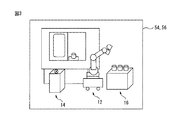
図1は、本発明の好適な実施形態に係る干渉領域設定装置により干渉領域を設定し得るシステムの一例として、加工システム10の概略構成を示す図である。加工システム10は、移動ロボット12、工作機械14及びワーク供給台16を含み、移動ロボット12は、設置面18に対して移動可能な走行部20と、走行部20に搭載されたロボット機構部(ロボットアーム)22と、ロボット機構部22の周囲の画像を取得するように構成された撮像装置24とを有する。
FIG. 1 is a diagram showing a schematic configuration of a
走行部20は、例えば台車であり、駆動源を備えた自走式のものでもよいし、人間(作業者)が押すことにより走行するものでもよい。ロボット機構部22は、例えば複数軸を有する多関節ロボットであり、図示例での撮像装置24は、ロボットの可動部(ロボットアームの先端若しくはロボットハンド26)又は走行部20に取り付けられたカメラである。なおカメラは三次元カメラ又は二次元カメラのいずれでもよいが、周囲の二次元画像(特に二次元の白黒画像)を撮像する二次元カメラがコスト面で有利である。また移動ロボット12の動作は、ロボット制御装置28によって制御可能である。なおロボット制御装置28には、作業者がロボット12の教示等の操作を行うための教示操作盤30が無線又は有線で接続されてもよい。
The
一例として、工作機械14はカバー32、カバー32により画定された加工室34、及びカバー32の一部に設けられた開閉可能な扉36を有し、扉36を介して加工室34内に搬送された加工対象物(ワーク)38に対して所定の加工を行うように構成されている。移動ロボット12は、ワーク供給台16の近傍まで走行してワーク供給台16上に載置された未加工のワーク38をハンド等で把持し、その後工作機械14の近傍まで走行して、把持したワークを加工室34内の所定位置に配置できるように構成されている。移動ロボット12はさらに、加工済のワークを加工室34から取り出して、所定の搬送先に搬送するように構成されてもよい。
As an example, the
システム10において、移動ロボット12が走行したりロボット機構部(ロボットアーム)22が作動したりすると、移動ロボット12の作業領域内にある工作機械14、ワーク供給台16、又は図示しない柱や構造物等(これらをまとめて障害物とも称する)と移動ロボット12とが干渉する場合がある。例えば、工作機械14の扉36が開いているときにロボット12が工作機械14の内部(加工室34)に進入して作業を行う場合、ロボット12は扉36やカバー32に干渉する虞がある。そこで本実施形態では、障害物の存在する領域である干渉領域を移動ロボット12(のロボット制御装置28)に対して設定し、ロボット12が該干渉領域内に進入しないようにロボット12の動作を制御する。なお移動ロボット12の作業領域とは、移動ロボット12の少なくとも一部が到達し得る最大の空間領域を意味し、例えば走行部20の最大走行範囲及びロボット機構部22の最大動作範囲に基づいて定めることができる。
In the
以下、干渉領域の設定の詳細について説明する。図2は、本実施形態に係る干渉領域設定装置40の機能ブロック図であり、ここではロボット制御装置28内にプロセッサやメモリ等の形態で組み込まれた例を示す。但し干渉領域設定装置40は、パーソナルコンピュータ等の、ロボット制御装置28とは別の装置とすることもでき、その場合は該装置とロボット制御装置28とは有線又は無線で通信可能となっていることが好ましい。
Hereinafter, details of the setting of the interference area will be described. FIG. 2 is a functional block diagram of the interference
干渉領域設定装置40は、移動ロボット12の作業領域内にある障害物(図示例では工作機械14及びワーク供給台16)の、基準座標系42上の形状、位置及び姿勢を障害物形状モデル(三次元モデル)として記憶する形状モデル記憶部44と、撮像装置24により撮像された、作業領域内の定位置にある形状的特徴物46の画像を解析し、ロボット座標系48における基準座標系42の位置及び姿勢を算出する位置姿勢算出部50と、ロボット座標系48における基準座標系42の位置姿勢と記憶された障害物形状モデルとから、ロボット座標系48における障害物の存在する領域である干渉領域を設定する干渉領域設定部52とを備える。
The interference
基準座標系42は、システム10の作業領域の基準となる座標系であり、例えば、設置面18に固定された固定座標系や、工作機械14について定義された座標系である。また基準座標系42と工作機械14又はワーク供給台16等の障害物との位置関係は既知であるとする。一方、ロボット座標系48は、移動ロボット12の基準となる座標系であり、例えば、走行部20や、ロボット機構部22のうち走行部20に対して不動の部分(旋回胴等)に固定された座標系である。
The
形状的特徴物(マーカ)46は、撮像装置24によって撮像可能な定位置に設けられた、一定の形状的特徴を有する構造物や印刷物を意味し、撮像装置24によって得られたマーカ46の画像の画像処理によって、ロボット座標系48におけるマーカ46の二次元位置又は三次元位置及び姿勢を算出することができる。マーカ46としては種々のものが使用可能であるが、例えば工作機械14が元々具備しているロゴや構造体をマーカとすることもできる。また、マーカ46と基準座標系42との位置関係は既知であるとする。従って撮像装置24を用いた画像解析により、ロボット座標系48における基準座標系42の位置及び姿勢を算出することができる。このような計算(座標変換)自体は、公知の手法で行うことができる。また複数のマーカを使用する場合は、それぞれの画像を取得した上で座標変換を行う。
The geometric feature (marker) 46 means a structure or printed matter provided at a fixed position that can be imaged by the
なおマーカ46の個数や形状は、算出すべきロボット座標系48におけるマーカ46の位置が二次元か三次元かによって適宜選択・変更可能である。例えば、移動ロボット12及び工作機械14等の障害物の高さが不変の場合は、マーカ46の高さ方向の位置を撮像によって求める必要がないので、単純な円等の形状を有するマーカを1つ又は2つ設ければ、設置面18に平行な平面内での、ロボット座標系48における基準座標系42の二次元位置及び姿勢を求めることができる。また、マーカが3つあれば、二次元カメラを用いた場合でも、ロボット座標系48における基準座標系42の三次元位置及び姿勢を求めることができる。或いは、マーカの形状(例えば図示するような互いに直交する十字線を円内に配置した形状)によっては、1つのマーカでもその画像処理によってロボット座標系48における基準座標系42の三次元位置及び姿勢を求めることができる。
The number and shape of the
一方、形状モデル記憶部44には、移動ロボット12の作業領域内にある障害物の、基準座標系42上の形状、位置及び姿勢が、予め障害物形状モデルとして記憶されている。例えば、工作機械14上に基準座標系42を定義し、基準座標系42上の工作機械14の形状モデルを、メモリ等の形状モデル記憶部44に記憶しておく。ここで形状モデルは、直方体などの要素を組み合わせて定義してもよいし、複数の点列からなる3Dマップで定義してもよい。
On the other hand, the shape
このようにして記憶された障害物形状モデルと、ロボット座標系48における基準座標系42の位置及び姿勢とから、ロボット座標系48における障害物の存在する領域である干渉領域を移動ロボット12(のロボット制御装置28)に設定することができる。具体的には、障害物形状モデルについて上述の座標変換を行うことにより、三次元の干渉領域を算出することができる。そしてロボット制御装置28は、移動ロボット12に対し、設定された干渉領域を回避するような動作を命令することができる。このようなマーカ46の撮像処理や干渉領域の設定処理は自動で行うことができるので、移動ロボット12が走行部20によって異なる場所へ移動した場合も、実用面で十分な精度の干渉領域の設定を自動で容易に行うことができ、移動の度に手動で干渉領域を設定する等の面倒な作業を不要とすることができる。
Based on the obstacle shape model stored in this way and the position and orientation of the reference coordinate
図3は、干渉領域設定装置40の表示命令機能について説明する図である。干渉領域設定装置40は、上述の干渉領域が設定された際に、干渉領域設定部52が設定した干渉領域(ここでは工作機械14及びワーク供給台16の占有領域)のロボット座標系48における位置及び姿勢に関する情報を、移動ロボット12とともに適当な表示部に表示させる機能(表示命令機能)を有する。なお表示部(表示画面)としては、例えばロボット制御装置28のディスプレイ54や教示操作盤30のディスプレイ56(図1参照)を使用することができるが、干渉領域設定装置40がパーソナルコンピュータ等のロボット制御装置28とは別装置である場合は、該パーソナルコンピュータ等のディスプレイ(図示せず)を使用することもでき、人間(作業者)が視認できるものであればどのような表示手段を用いてもよい。なお障害物については、その外形(輪郭)のみを簡易的に表示してもよい。また画面表示させる情報は三次元的なものが好ましいが、二次元的なものでもよい。
FIG. 3 is a diagram for explaining the display command function of the interference
上述の表示機能により、作業者は、移動ロボット12に干渉し得る障害物の存在を確認できるとともに、実際のシステム10の状態(各機器の配置)と、画面表示されたものとを比較することができる。例えば、カメラ24を移動ロボット12に固定するボルトの緩み等によって、カメラ24の位置又は姿勢が所定のものからずれている場合、そのずれが目視では識別が困難な僅かなものであっても、カメラ24によるマーカ46の撮像結果(干渉物の位置検出)には大きく影響するので、画面表示される各機器の配置は実際のものから大きく乖離することになり、この状態でロボットを稼働させると干渉が生じる虞がある。従って作業者は、ロボット座標系における干渉領域の画面表示によって、カメラ24の位置ずれ等、実際のシステムにおける設定や構造に関する不具合の有無を知ることができる。
With the display function described above, the operator can confirm the presence of an obstacle that may interfere with the
また、干渉領域設定装置40は、干渉領域を新たに設定した際に、「干渉領域が変更されました。確認してください」等の、人間(作業者)に確認を求めるメッセージを教示操作盤30のディスプレイ56等の適当な表示画面に表示したり、上記メッセージを音声として出力したりする出力機能を具備してもよい。その場合、人間は実際の移動ロボット12と工作機械14等の障害物の位置関係と、画面表示された移動ロボット12と干渉領域との位置関係を比較して、システム10の設定に誤りがないか、カメラ24の位置ずれ等の構造的な不具合がないか、等を確認し、問題がなければ、キーボードや操作パネル等の適当な入力手段を介して、干渉領域に関する設定内容を確認した旨を干渉領域設定装置40に入力する。
Further, when the interference
そして干渉領域設定装置40は、干渉領域を設定してからこの入力を受け付けるまでの間は、移動ロボット12の動作を禁止する動作禁止機能を備えることができる。より具体的には、作業者からの入力があるまでは、移動ロボット12の動作を禁止する旨の命令(信号等)をロボット制御装置28に送信することができる。このようにして、人間が干渉領域の設定に問題ないことを確認するまでの間は、移動ロボットの動作を禁止することができ、不正確又は不適切な干渉領域に基づいてロボットが動作することを確実に防止することができる。
The interference
10 加工システム
12 移動ロボット
14 工作機械
16 ワーク供給台
24 撮像装置
28 ロボット制御装置
30 教示操作盤
40 干渉領域設定装置
42 基準座標系
44 形状モデル記憶部
46 形状的特徴物
48 ロボット座標系
50 位置姿勢算出部
52 干渉領域設定部
DESCRIPTION OF
Claims (4)
前記移動ロボットの作業領域内にある障害物の、前記作業領域の基準となる基準座標系上の形状、位置及び姿勢を障害物形状モデルとして記憶する形状モデル記憶部と、
前記撮像装置により撮像された、前記作業領域内の定位置にある形状的特徴物の画像を解析し、前記移動ロボットの基準となるロボット座標系における前記基準座標系の位置及び姿勢を算出する位置姿勢算出部と、
前記ロボット座標系における前記基準座標系の位置姿勢と前記障害物形状モデルとから、前記ロボット座標系における障害物の存在する領域である干渉領域を自動で設定する干渉領域設定部と、を備える干渉領域設定装置。 Setting an interference area for a mobile robot having a movable traveling unit, a robot mechanism unit mounted on the traveling unit, and an imaging device configured to acquire an image around the robot mechanism unit An interference area setting device for
A shape model storage unit that stores, as an obstacle shape model, the shape, position, and orientation of an obstacle in the work area of the mobile robot on a reference coordinate system that is a reference of the work area;
A position for analyzing the image of the geometric feature at a fixed position in the work area, which is imaged by the imaging device, and calculating the position and orientation of the reference coordinate system in the robot coordinate system serving as the reference of the mobile robot An attitude calculation unit;
An interference area setting unit that automatically sets an interference area that is an area where an obstacle exists in the robot coordinate system from the position and orientation of the reference coordinate system in the robot coordinate system and the obstacle shape model Area setting device.
Priority Applications (4)
| Application Number | Priority Date | Filing Date | Title |
|---|---|---|---|
| JP2016238688A JP6457469B2 (en) | 2016-12-08 | 2016-12-08 | Mobile robot interference area setting device |
| CN201711172940.9A CN108177162B (en) | 2016-12-08 | 2017-11-22 | The interference region setting device of mobile robot |
| DE102017128543.1A DE102017128543B4 (en) | 2016-12-08 | 2017-12-01 | NOISE ZONE ADJUSTMENT DEVICE FOR A MOBILE ROBOT |
| US15/830,216 US10675759B2 (en) | 2016-12-08 | 2017-12-04 | Interference region setting apparatus for mobile robot |
Applications Claiming Priority (1)
| Application Number | Priority Date | Filing Date | Title |
|---|---|---|---|
| JP2016238688A JP6457469B2 (en) | 2016-12-08 | 2016-12-08 | Mobile robot interference area setting device |
Publications (2)
| Publication Number | Publication Date |
|---|---|
| JP2018094641A JP2018094641A (en) | 2018-06-21 |
| JP6457469B2 true JP6457469B2 (en) | 2019-01-23 |
Family
ID=62202045
Family Applications (1)
| Application Number | Title | Priority Date | Filing Date |
|---|---|---|---|
| JP2016238688A Active JP6457469B2 (en) | 2016-12-08 | 2016-12-08 | Mobile robot interference area setting device |
Country Status (4)
| Country | Link |
|---|---|
| US (1) | US10675759B2 (en) |
| JP (1) | JP6457469B2 (en) |
| CN (1) | CN108177162B (en) |
| DE (1) | DE102017128543B4 (en) |
Families Citing this family (21)
| Publication number | Priority date | Publication date | Assignee | Title |
|---|---|---|---|---|
| JP6994411B2 (en) * | 2018-02-28 | 2022-01-14 | オークマ株式会社 | Machine tool system |
| JP6816070B2 (en) * | 2018-08-24 | 2021-01-20 | ファナック株式会社 | Interference avoidance device and robot system |
| JP7147571B2 (en) * | 2019-01-15 | 2022-10-05 | オムロン株式会社 | Route generation device, route generation method, and route generation program |
| JP2020199625A (en) * | 2019-06-13 | 2020-12-17 | ファナック株式会社 | Simulation device |
| US12358148B2 (en) * | 2019-09-11 | 2025-07-15 | Dmg Mori Co., Ltd. | Robot-mounted moving device, system, and machine tool |
| JP7384602B2 (en) * | 2019-09-12 | 2023-11-21 | ファナック株式会社 | robot control device |
| WO2021049028A1 (en) * | 2019-09-13 | 2021-03-18 | 三菱電機株式会社 | Numerical control device and machine learning device |
| WO2021140952A1 (en) * | 2020-01-08 | 2021-07-15 | ソニーグループ株式会社 | Information processing device, information processing method, and program |
| CN116113896B (en) * | 2020-08-31 | 2025-10-28 | 发那科株式会社 | Numerical control systems |
| EP3974936B1 (en) * | 2020-09-25 | 2023-06-07 | Sick Ag | Configuration of a visualisation device for a machine area |
| US12466074B2 (en) * | 2020-10-30 | 2025-11-11 | Dmg Mori Co., Ltd. | Image processing method, image processing apparatus, robot-mounted transfer device, and system |
| CN112454354B (en) * | 2020-11-10 | 2022-05-03 | 中国电子工程设计院有限公司 | Working method and device of industrial robot and storage medium |
| CN112605999B (en) * | 2020-12-22 | 2022-01-18 | 杭州北冥星眸科技有限公司 | Robot obstacle detection method and system based on infrared deep camera technology |
| US20240165811A1 (en) * | 2021-04-28 | 2024-05-23 | Fanuc Corporation | Device for setting safety parameters, teaching device and method |
| JP7541955B2 (en) * | 2021-05-06 | 2024-08-29 | 株式会社神戸製鋼所 | Robot travelling cart position determination device, method and program |
| JP6957781B1 (en) * | 2021-06-14 | 2021-11-02 | Dmg森精機株式会社 | Self-propelled device |
| JP7637609B2 (en) | 2021-11-05 | 2025-02-28 | 株式会社日立ハイテク | Mobile Robot System |
| CN117636229A (en) * | 2022-08-10 | 2024-03-01 | 北京小米机器人技术有限公司 | Interference object handling methods, devices, robots and electronic equipment |
| CN115816446B (en) * | 2022-11-24 | 2025-04-04 | 广西大学 | Coordinated motion control method for mobile manipulator in hilly and mountainous areas |
| JP2025042154A (en) * | 2023-09-14 | 2025-03-27 | 川崎重工業株式会社 | Teaching support device, teaching support method, and teaching support program |
| JP2025115330A (en) * | 2024-01-25 | 2025-08-06 | 川崎重工業株式会社 | Method and device for checking interference between workpiece transport robots |
Family Cites Families (22)
| Publication number | Priority date | Publication date | Assignee | Title |
|---|---|---|---|---|
| JPH085028B2 (en) | 1990-02-28 | 1996-01-24 | 株式会社日立製作所 | Collision determination method for mobile body and collision determination device |
| JP2001300875A (en) * | 2000-04-19 | 2001-10-30 | Denso Corp | Robot system |
| JP3782679B2 (en) * | 2001-05-09 | 2006-06-07 | ファナック株式会社 | Interference avoidance device |
| JP3945279B2 (en) * | 2002-03-15 | 2007-07-18 | ソニー株式会社 | Obstacle recognition apparatus, obstacle recognition method, obstacle recognition program, and mobile robot apparatus |
| JP2005081445A (en) | 2003-09-04 | 2005-03-31 | Fanuc Ltd | Interference region confirmation device of robot |
| JP3994950B2 (en) * | 2003-09-19 | 2007-10-24 | ソニー株式会社 | Environment recognition apparatus and method, path planning apparatus and method, and robot apparatus |
| JP2006239844A (en) * | 2005-03-04 | 2006-09-14 | Sony Corp | Obstacle avoidance device, obstacle avoidance method, obstacle avoidance program, and mobile robot device |
| JP4159577B2 (en) * | 2005-12-13 | 2008-10-01 | ファナック株式会社 | Interlock automatic setting device and automatic setting method between a plurality of robots |
| CN101888920B (en) * | 2007-12-07 | 2012-10-03 | 株式会社安川电机 | Robot movement regulating method, robot system, and robot movement regulating device |
| DE102008052579A1 (en) * | 2008-10-21 | 2010-04-22 | Joachim Franek | Safety system for working device, comprises unit and camera which is arranged at unit, where movement of unit is monitored by camera, based on degree of freedom of unit |
| JP2010162635A (en) | 2009-01-14 | 2010-07-29 | Fanuc Ltd | Method for correcting position and attitude of self-advancing robot |
| JP5494384B2 (en) * | 2010-09-16 | 2014-05-14 | 株式会社デンソーウェーブ | Robot monitoring system |
| KR101850386B1 (en) * | 2011-04-19 | 2018-04-19 | 엘지전자 주식회사 | Robot cleaner and controlling method of the same |
| KR20140045025A (en) * | 2012-10-08 | 2014-04-16 | 송세경 | Mobile robot and mthod for moving of mobile robot using virtual fence |
| JP5742862B2 (en) * | 2013-03-18 | 2015-07-01 | 株式会社安川電機 | Robot apparatus and workpiece manufacturing method |
| WO2015045834A1 (en) * | 2013-09-30 | 2015-04-02 | 独立行政法人産業技術総合研究所 | Marker image processing system |
| JP5911933B2 (en) * | 2014-09-16 | 2016-04-27 | ファナック株式会社 | Robot system for setting the robot motion monitoring area |
| JP5980873B2 (en) * | 2014-10-17 | 2016-08-31 | ファナック株式会社 | Robot interference area setting device |
| US10076840B2 (en) * | 2015-04-03 | 2018-09-18 | Canon Kabushiki Kaisha | Information processing apparatus, information processing method, and program |
| CN105437232B (en) * | 2016-01-11 | 2017-07-04 | 湖南拓视觉信息技术有限公司 | A kind of method and device of control multi-joint Mobile Robot Obstacle Avoidance |
| CN106052674B (en) * | 2016-05-20 | 2019-07-26 | 青岛克路德机器人有限公司 | A kind of SLAM method and system of Indoor Robot |
| US10131053B1 (en) * | 2016-09-14 | 2018-11-20 | X Development Llc | Real time robot collision avoidance |
-
2016
- 2016-12-08 JP JP2016238688A patent/JP6457469B2/en active Active
-
2017
- 2017-11-22 CN CN201711172940.9A patent/CN108177162B/en active Active
- 2017-12-01 DE DE102017128543.1A patent/DE102017128543B4/en active Active
- 2017-12-04 US US15/830,216 patent/US10675759B2/en active Active
Also Published As
| Publication number | Publication date |
|---|---|
| DE102017128543A1 (en) | 2018-06-14 |
| DE102017128543B4 (en) | 2022-02-03 |
| CN108177162B (en) | 2019-09-27 |
| CN108177162A (en) | 2018-06-19 |
| JP2018094641A (en) | 2018-06-21 |
| US20180161978A1 (en) | 2018-06-14 |
| US10675759B2 (en) | 2020-06-09 |
Similar Documents
| Publication | Publication Date | Title |
|---|---|---|
| JP6457469B2 (en) | Mobile robot interference area setting device | |
| JP4763074B2 (en) | Measuring device and measuring method of position of tool tip of robot | |
| CN107891414B (en) | Robot system | |
| JP4844453B2 (en) | Robot teaching apparatus and teaching method | |
| JP6420229B2 (en) | A robot system including a video display device that superimposes and displays an image of a virtual object on a video of a robot | |
| JP6855492B2 (en) | Robot system, robot system control device, and robot system control method | |
| US12337474B2 (en) | Robot teaching system | |
| JP5850958B2 (en) | Robot programming device for creating a robot program for imaging a workpiece | |
| JP2005106825A (en) | Method and apparatus for determining position and orientation of image receiving device | |
| KR20040103382A (en) | Robot system | |
| JP7366264B2 (en) | Robot teaching method and robot working method | |
| CN115003464B (en) | Robotic system | |
| JP2019063955A (en) | Robot system, operation control method and operation control program | |
| JP2010188439A (en) | Method and apparatus for calculating parameter | |
| US11630436B2 (en) | Measurement program selection assisting apparatus and measurement control apparatus | |
| US20230214083A1 (en) | Measurement program selection assisting apparatus and measurement control apparatus | |
| US20250135641A1 (en) | Terminal device | |
| JP6031368B2 (en) | Correlation positioning method with workpiece | |
| US12558784B2 (en) | Motion trajectory generation method for robot, motion trajectory generation apparatus for robot, robot system, and program | |
| JP2006051550A (en) | Position teaching apparatus and position teaching method for moving body | |
| JP2010149225A (en) | Robot system, device and method for controlling robot system | |
| JP7278637B2 (en) | Self-propelled moving device | |
| JP7660686B2 (en) | ROBOT CONTROL DEVICE, ROBOT CONTROL SYSTEM, AND ROBOT CONTROL METHOD | |
| JP2020073302A (en) | Robots and robot systems | |
| JP2016078142A (en) | Method for control of robot device, and robot device |
Legal Events
| Date | Code | Title | Description |
|---|---|---|---|
| A975 | Report on accelerated examination |
Free format text: JAPANESE INTERMEDIATE CODE: A971005 Effective date: 20180316 |
|
| A977 | Report on retrieval |
Free format text: JAPANESE INTERMEDIATE CODE: A971007 Effective date: 20180628 |
|
| A131 | Notification of reasons for refusal |
Free format text: JAPANESE INTERMEDIATE CODE: A131 Effective date: 20180703 |
|
| A521 | Request for written amendment filed |
Free format text: JAPANESE INTERMEDIATE CODE: A523 Effective date: 20180828 |
|
| TRDD | Decision of grant or rejection written | ||
| A01 | Written decision to grant a patent or to grant a registration (utility model) |
Free format text: JAPANESE INTERMEDIATE CODE: A01 Effective date: 20181127 |
|
| A61 | First payment of annual fees (during grant procedure) |
Free format text: JAPANESE INTERMEDIATE CODE: A61 Effective date: 20181220 |
|
| R150 | Certificate of patent or registration of utility model |
Ref document number: 6457469 Country of ref document: JP Free format text: JAPANESE INTERMEDIATE CODE: R150 |