JP4999146B2 - Inner fin and heat sink equipped with the inner fin - Google Patents
Inner fin and heat sink equipped with the inner fin Download PDFInfo
- Publication number
- JP4999146B2 JP4999146B2 JP2006131170A JP2006131170A JP4999146B2 JP 4999146 B2 JP4999146 B2 JP 4999146B2 JP 2006131170 A JP2006131170 A JP 2006131170A JP 2006131170 A JP2006131170 A JP 2006131170A JP 4999146 B2 JP4999146 B2 JP 4999146B2
- Authority
- JP
- Japan
- Prior art keywords
- herringbone
- cooling fluid
- inner fin
- tank body
- heat sink
- Prior art date
- Legal status (The legal status is an assumption and is not a legal conclusion. Google has not performed a legal analysis and makes no representation as to the accuracy of the status listed.)
- Expired - Fee Related
Links
Images


Landscapes
- Heat-Exchange Devices With Radiators And Conduit Assemblies (AREA)
Description
本発明は、ヒートシンク等の熱交換器に設けられるインナーフィン及びこのインナーフィンを備えたヒートシンクに関する。 The present invention relates to an inner fin provided in a heat exchanger such as a heat sink, and a heat sink including the inner fin.
一般に、パソコンのCPU(Central Processing
Unit)、サイリスタや電力用コンデンサのような電子部品等の熱源には、該熱源から発生した熱を放出させるため、ヒートシンクが設けられており、このヒートシンクは、扁平な箱状のタンク本体の内部空間を流通する冷却流体によって該タンク本体の外面に装着された熱源を冷却するようになっている。
Generally, the CPU (Central Processing) of a personal computer
Unit), heat sources such as thyristors and power capacitors are provided with a heat sink in order to release the heat generated from the heat source. This heat sink is provided inside the flat box-shaped tank body. A heat source mounted on the outer surface of the tank body is cooled by a cooling fluid flowing through the space.
従来、この種のヒートシンクには、プレートを積層して形成されるプレート式熱交換器が用いられることがあり、このプレート式熱交換器は、部品点数が少なく組立性に優れていることが知られている。また、プレート式熱交換器には、熱交換効率を高めるため、積層されるプレートの表面に凹凸加工が施されることがあり、特に、ヘリンボーンと呼ばれる魚の骨形状の凹凸加工をプレートの表面に施したタイプのプレート式熱交換器は、冷却流体の乱流効果がプレートの全幅に渡って生じるため、他のタイプのものと比べて、熱交換効率が高くなることが知られている(例えば、特許文献1参照)。 Conventionally, a plate-type heat exchanger formed by laminating plates is sometimes used for this type of heat sink, and this plate-type heat exchanger has a small number of parts and is excellent in assemblability. It has been. In order to increase heat exchange efficiency, plate-type heat exchangers are sometimes subjected to uneven processing on the surface of the stacked plates. In particular, a fish bone-shaped uneven processing called herringbone is applied to the plate surface. It is known that the plate-type heat exchanger of the applied type has higher heat exchange efficiency than other types because the turbulent flow effect of the cooling fluid occurs over the entire width of the plate (for example, , See Patent Document 1).
しかしながら、このようにプレートの表面にヘリンボーン状の凹凸加工を施したプレート式熱交換器をヒートシンクに使用した場合には、熱源の装着面が平坦でないため、熱伝達効率を高めることができず、却って熱交換効率が低下するといった問題があった。そのため、プレート式熱交換器をヒートシンクに使用する場合には、熱源の装着面に凹凸加工を施さずに、プレートの表面を平坦に形成させると共に、タンク本体の内部空間にインナーフィンを挿入し、熱源とタンク本体間の熱伝達効率を高めるようにしている(例えば、特許文献2参照)。
しかしながら、上記した特許文献2に記載されたヒートシンクでは、インナーフィンが複雑な形状を成しているため、製造過程において高価な金型が必要となり、製造コストが嵩むといった問題があった。
However, in the heat sink described in
また、上記したようにプレート式熱交換器をヒートシンクに使用した場合には、タンク本体への冷却流体の出入口の取り付け位置が、プレート式熱交換器の構造上、タンク本体の両端部に限定され、タンク本体の内部空間に形成できる流路パターンが特定のパターンに限られてしまうため、ヒートシンクの設計の自由度を高めることができないといった問題もあった。 In addition, when a plate heat exchanger is used as a heat sink as described above, the mounting position of the cooling fluid inlet / outlet to the tank body is limited to both ends of the tank body due to the structure of the plate heat exchanger. Moreover, since the flow path pattern that can be formed in the internal space of the tank body is limited to a specific pattern, there is a problem that the degree of freedom in designing the heat sink cannot be increased.
本発明は、上記した課題を解決すべくなされたものであり、単純な形状を成し、製造コストの低減化を図ることができると共に、流路パターンの設計の自由度を高めることができるインナーフィン及びこのインナーフィンを備えたヒートシンクを提供することを目的とするものである。 The present invention has been made to solve the above-described problems, and has an inner shape that has a simple shape, can reduce the manufacturing cost, and can increase the degree of freedom in designing the flow path pattern. An object of the present invention is to provide a fin and a heat sink including the inner fin.
上記目的を達成するため、本発明は、熱交換器に設けられるインナーフィンであって、中骨部の両側に枝骨部が形成されたヘリンボーン状部材を、枝骨部同士が交差するように互いに逆向きに積重することにより構成されていることを特徴とする。 In order to achieve the above object, the present invention provides an inner fin provided in a heat exchanger, in which a herringbone-like member having a branch bone part formed on both sides of a middle bone part is crossed between the branch bone parts. It is characterized by being stacked in opposite directions.
そして、前記ヘリンボーン状部材の周りには外枠部が形成されており、該外枠部はヒートシンクのタンク本体の一部を構成していてもよい。 An outer frame portion may be formed around the herringbone-like member, and the outer frame portion may constitute a part of the tank body of the heat sink.
また、前記互いに逆向きに積重される各ヘリンボーン状部材は、それぞれ、略相似形状を成す複数のヘリンボーン状相似部材を同一向きに積重することにより構成されており、該積重されたヘリンボーン状相似部材は内側に向かって次第に外形が小さくなるように形成されていてもよい。 Each of the herringbone-like members stacked in the opposite directions is configured by stacking a plurality of herringbone-like members having substantially similar shapes in the same direction, and the stacked herringbones The shape-similar member may be formed so that the outer shape gradually becomes smaller inward.
さらに、前記互いに逆向きに積重される各ヘリンボーン状部材は、それぞれ、内側に向かって細くなる形状を有していてもよい。 Further, the herringbone-like members stacked in the opposite directions may each have a shape that narrows toward the inside.
さらにまた、前記ヘリンボーン状部材の枝骨部の交差部には、該各枝骨部同士が面接合可能なように接合部が形成されていてもよい。 Furthermore, a joint portion may be formed at the intersection of the branch bone portions of the herringbone member so that the respective branch bone portions can be surface-joined.
また、本発明は、扁平な箱状のタンク本体の内部空間を流通する冷却流体によって該タンク本体の外側平坦面に装着された熱源を冷却するヒートシンクであって、前記タンク本体の内部空間には、上記したインナーフィンが設けられていることを特徴とする。 Further, the present invention is a heat sink that cools a heat source mounted on an outer flat surface of the tank body by a cooling fluid that circulates in the interior space of the flat box-shaped tank body. The above-described inner fin is provided.
そして、前記ヒートシンクのインナーフィンは、前記タンク本体の略中央に配置され、前記インナーフィンの周囲には、環状の冷却流体用流通路が形成されており、前記タンク本体の対角位置には、前記冷却流体用流通路に連通するように冷却流体入口部及び冷却流体出口部がそれぞれ設けられていてもよい。 And the inner fin of the heat sink is arranged at the approximate center of the tank main body, an annular cooling fluid flow passage is formed around the inner fin, and the diagonal position of the tank main body is A cooling fluid inlet and a cooling fluid outlet may be provided so as to communicate with the cooling fluid flow passage.
また、前記ヒートシンクのインナーフィンは、前記中骨部が前記タンク本体の側壁に当接するように配置され、前記インナーフィンの周囲には、U字状の冷却流体用流通路が形成されており、前記タンク本体には、前記冷却流体用流通路の両端部に連通するように冷却流体入口部及び冷却流体出口部がそれぞれ設けられていてもよい。 Further, the inner fin of the heat sink is disposed so that the middle bone portion comes into contact with the side wall of the tank body, and a U-shaped cooling fluid flow passage is formed around the inner fin, The tank body may be provided with a cooling fluid inlet and a cooling fluid outlet so as to communicate with both ends of the cooling fluid flow passage.
さらに、前記タンク本体の外側平坦面に対向する面には、前記タンク本体の内部空間側に突出するヘリンボーン状突部が前記ヘリンボーン状部材と同一形状を成すように形成されており、該ヘリンボーン状突部には、枝骨部同士が交差するように前記ヘリンボーン状突部と逆向きに前記ヘリンボーン状部材が積重されていてもよい。 Furthermore, a herringbone-like protrusion projecting toward the inner space of the tank body is formed on the surface facing the outer flat surface of the tank body so as to have the same shape as the herringbone-like member. The herringbone-shaped member may be stacked on the protrusion so as to cross the herringbone-shaped protrusion so that the branch bone portions intersect each other.
さらにまた、前記熱源が装着される外側平坦面を有する第1のプレート部材と、該第1のプレート部材に重合し、該第1のプレート部材と共に前記タンク本体を形成する樹脂製の第2のプレート部材とを備え、該第2のプレート部材には、前記タンク本体の内部空間側に突出するヘリンボーン状突部が前記ヘリンボーン状部材と同一形状を成すように前記第2のプレート部材と一体成形されており、該ヘリンボーン状突部には、枝骨部同士が交差するように逆向きに前記ヘリンボーン状部材が積重されていてもよい。 Furthermore, a first plate member having an outer flat surface on which the heat source is mounted, and a resin-made second material that is superposed on the first plate member and forms the tank body together with the first plate member. A plate member, and the second plate member is integrally formed with the second plate member such that a herringbone-like protrusion protruding toward the inner space of the tank body has the same shape as the herringbone-like member. The herringbone-like protrusions may be stacked with the herringbone-like members in opposite directions so that the branch bone portions intersect each other.
本発明によれば、枝骨部同士が交差するように互いに逆向きにヘリンボーン状部材を積重することによりインナーフィンが構成されているため、冷却流体は、枝骨部により十分に攪拌され、全体に渡って均等に流通するようになるため、熱交換効率の向上を図ることができる。 According to the present invention, since the inner fin is configured by stacking herringbone-like members in opposite directions so that the branch bone portions intersect each other, the cooling fluid is sufficiently stirred by the branch bone portion, Since it comes to distribute | circulate uniformly throughout, the improvement of heat exchange efficiency can be aimed at.
また、インナーフィンの形状が単純なヘリンボーン状を成しているため、金型費が安価となり、製造コストの低減化を図ることができる。 Further, since the shape of the inner fin is a simple herringbone shape, the mold cost is reduced, and the manufacturing cost can be reduced.
さらに、ヒートシンクに上記インナーフィンを設けた場合には、インナーフィンによりタンク本体の内部空間を簡単に仕切ることができるため、タンク本体への冷却流体の出入口の配置が容易となり、冷却流体用流通路の流路パターンの設計の自由度を高めることもできる等、種々の優れた効果を得ることができる。 Further, when the inner fin is provided on the heat sink, the inner space of the tank body can be easily partitioned by the inner fin, so that the arrangement of the cooling fluid inlet / outlet to the tank body is facilitated, and the cooling fluid flow passage is provided. Various excellent effects can be obtained, for example, the degree of freedom in designing the flow path pattern can be increased.
以下、図面を参照しつつ、本発明の実施の形態について説明する。 Hereinafter, embodiments of the present invention will be described with reference to the drawings.
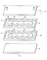
先ず、図1を参照しつつ、本発明の第1の実施の形態に係るヒートシンクについて説明する。ここで、図1は本実施の形態に係るヒートシンクを示す分解斜視図である。 First, a heat sink according to a first embodiment of the present invention will be described with reference to FIG. Here, FIG. 1 is an exploded perspective view showing the heat sink according to the present embodiment.
本実施の形態に係るヒートシンク1は、扁平な矩形箱状のタンク本体2の内部空間にインナーフィン3が設けられて構成されている。
The
タンク本体2は、プレス成形品である2枚のプレート部材4,5の外周縁部に形成された立ち上がり部6,7同士を重合することにより箱状に形成されている。そして、タンク本体2の外面のうちの少なくとも一方の外面8(図1では下面)は平坦に形成され、該平坦面8に、電子部品等の熱源が密着可能なようになっている。また、タンク本体2の平坦面8に対向する面9には対角位置に、それぞれ冷却流体入口10及び冷却流体出口11が接続され、さらに、タンク本体2の外周部には、立ち上がり部6,7により側壁12が形成されている。
The
インナーフィン3は、プレス打ち抜き加工により魚の骨状に形成された2個一対のヘリンボーン状部材13,13によって構成されている。各ヘリンボーン部材13は、直線状に形成された中骨部14と、中骨部14の両側に形成され、くの字状を成す複数の枝骨部15とから構成されており、中骨部14同士が一致すると共に枝骨部15,15同士が交差するように互いに逆向きに積重されている。そして、インナーフィン3は、タンク本体2の内部空間の略中央に配置されており、その厚みはタンク本体2の内部空間の高さに等しく、インナーフィン3によってタンク本体2の内部空間が仕切られるようになっている。これにより、インナーフィン3の周囲には、環状の冷却流体用流通路16が形成され、この冷却流体用流通路16に冷却流体入口10及び冷却流体出口11がそれぞれ連通するようになっている。
The
このように構成されたヒートシンク1において、冷却流体は、冷却流体入口10からタンク本体2の内部空間に流入し、冷却流体用流通路16を流通する。この時、ヘリンボーン状部材13の枝骨部15同士が交差するように配置されているため、冷却流体は、枝骨部15により十分に攪拌されながら冷却流体用流通路16全体に渡って均等に流通し、タンク本体2の平坦面8に密着された熱源から効率良く熱を吸収した後、冷却流体出口11を通って、外部に流出する。
In the
次に、図2を参照しつつ、本発明の第2の実施の形態に係るヒートシンクについて説明する。ここで、図2は本実施の形態に係るヒートシンクを示す分解斜視図である。なお、以下の説明では、説明の簡略化のため、上記した第1の実施の形態の場合と同様の構成については、図2中、図1と同一の符号を付し、詳細な説明は省略する。 Next, a heat sink according to a second embodiment of the present invention will be described with reference to FIG. Here, FIG. 2 is an exploded perspective view showing the heat sink according to the present embodiment. In the following description, for simplification of description, the same reference numerals as those in FIG. 1 are given to the same configurations as those in the first embodiment described above, and detailed description thereof is omitted. To do.
本実施の形態に係るヒートシンク21において、インナーフィン22は、プレス打ち抜き加工により魚の骨状に形成された2個一対のヘリンボーン状部材23,23により構成されている。各ヘリンボーン部材23は、直線状に形成された中骨部24と、中骨部24の両側に形成され、くの字状を成す複数の枝骨部25とから構成されており、中骨部24同士が一致すると共に枝骨部25,25同士が交差するように互いに逆向きに積重されている。
In the
そして、インナーフィン22は、各中骨部24の一方の端部がそれぞれ延出し、該各延出部26がタンク本体2の側壁12に当接するようにタンク本体2の内部空間に配置されており、その厚みはタンク本体2の内部空間の高さに等しく、インナーフィン22によってタンク本体2の内部空間が仕切られるようになっている。これにより、インナーフィン22の周囲には、U字状を成す2パスの冷却流体用流通路27が形成されている。また、タンク本体2には、この冷却流体用流通路27の両端部にそれぞれ連通するように冷却流体入口10及び冷却流体出口11が接続されている。
The inner fin 22 is disposed in the internal space of the
このように構成されたヒートシンク21において、冷却流体入口10からタンク本体2の内部空間に流入した冷却流体は、枝骨部15により十分に攪拌されながら冷却流体用流通路16全体に渡って均等に流通し、タンク本体2の平坦面8に密着された熱源から効率良く熱を吸収した後、冷却流体出口11を通って、外部に流出する。
In the
次に、図3を参照しつつ、本発明の第3の実施の形態に係るヒートシンクについて説明する。ここで、図3は本実施の形態に係るヒートシンクを示す分解斜視図である。なお、以下の説明では、説明の簡略化のため、上記した第1の実施の形態の場合と同様の構成については、図3中、図1と同一の符号を付し、詳細な説明は省略する。 Next, a heat sink according to a third embodiment of the present invention will be described with reference to FIG. Here, FIG. 3 is an exploded perspective view showing the heat sink according to the present embodiment. In the following description, for simplification of description, the same reference numerals as those in FIG. 1 are given to the same configurations as those in the first embodiment described above, and detailed description thereof is omitted. To do.
本実施の形態に係るヒートシンク31は、2枚のプレート部材32,33の間に2枚のインナーフィン34,34を互いに逆向きに積重して介装することにより形成されている。そして、プレート部材32,33の外面のうちの少なくとも一方の外面(図3では下面)は平坦に形成され、該平坦面35に、電子部品等の熱源が密着可能なようになっている。
The
インナーフィン34は、プレス打ち抜き加工により魚の骨状に形成されたヘリンボーン状部材36と、ヘリンボーン状部材36の周りに形成された矩形状の外枠部37とから構成されており、外枠部37はタンク本体2の一部を構成するようになっている。すなわち、各インナーフィン34,34の外枠部37,37とプレート部材32,33とによりタンク本体2が構成されている。また、各ヘリンボーン部材36は、直線状に形成された中骨部38と、中骨部38の両側に形成され、くの字状を成す複数の枝骨部39とから構成されており、中骨部38同士が一致すると共に枝骨部39同士が交差するようになっている。
The
このように本実施の形態に係るヒートシンク31によれば、プレート部材32,33とインナーフィン34,34をそれぞれプレス加工により成形した後、それらを積重してロウ付けするだけで、簡単にヒートシンク31を製造することができるため、製造コストの低減化を図ることができる。
As described above, according to the
次に、図4及び図5を参照しつつ、本発明の第4の実施の形態に係るヒートシンクについて説明する。ここで、図4は本実施の形態に係るヒートシンクのインナーフィンを示す平面図、図5はヒートシンクの断面図である。なお、以下の説明では、説明の簡略化のため、上記した第1の実施の形態の場合と同様の構成については、図4及び図5中、図1と同一の符号を付し、詳細な説明は省略する。 Next, a heat sink according to a fourth embodiment of the present invention will be described with reference to FIGS. Here, FIG. 4 is a plan view showing an inner fin of the heat sink according to the present embodiment, and FIG. 5 is a cross-sectional view of the heat sink. In the following description, for simplification of description, the same components as those in the first embodiment described above are denoted by the same reference numerals in FIG. 4 and FIG. Description is omitted.
本実施の形態に係るヒートシンク41において、インナーフィン42は、プレス打ち抜き加工により魚の骨状に形成されたヘリンボーン状部材43,43を互いに逆向きに積重することにより構成されている。各ヘリンボーン部材43は、それぞれ、略相似形状を成す複数(図4及び図5では2枚)のヘリンボーン状相似部材44,45を同一向きに積重することにより構成されており、該積重されたヘリンボーン状相似部材44,45は内側に向かって次第に外形が小さくなるように形成されている。
In the
また、各ヘリンボーン状相似部材44,45は、それぞれ、直線状に形成された中骨部46,47と、中骨部46,47の両側に形成され、くの字状を成す複数の枝骨部48,49とから構成されており、中骨部47同士が一致すると共に枝骨部49同士が交差するように設けられている。
Each of the herringbone-
このように本実施の形態に係るヒートシンク41によれば、タンク本体2の内部空間に流入した冷却流体は、枝骨部48,49により十分に攪拌されながら冷却流体用流通路16全体に渡って澱むことなく、円滑に流通するようになる。したがって、ヒートシンク41に密着された熱源から効率良く熱を吸収することができ、熱交換効率の向上を図ることができる。
As described above, according to the
次に、図6を参照しつつ、本発明の第5の実施の形態に係るヒートシンクについて説明する。ここで、図6は本実施の形態に係るヒートシンクを示す分解斜視図である。なお、以下の説明では、説明の簡略化のため、上記した第1の実施の形態の場合と同様の構成については、図6中、図1と同一の符号を付し、詳細な説明は省略する。 Next, a heat sink according to a fifth embodiment of the present invention will be described with reference to FIG. Here, FIG. 6 is an exploded perspective view showing the heat sink according to the present embodiment. In the following description, for simplification of description, the same reference numerals as those in FIG. 1 are given to the same configurations as those in the first embodiment described above, and detailed description thereof is omitted. To do.
本実施の形態に係るヒートシンク51は、熱源が装着される外側平坦面52を有するアルミニウム又は銅製の第1のプレート部材53と、第1のプレート部材53に重合し、第1のプレート部材53と共に扁平な矩形箱状のタンク本体2を形成する樹脂製の第2のプレート部材54と、タンク本体2の内部空間に配置されるアルミニウム又は銅製のヘリンボーン状部材13とを備えている。
The
第2のプレート部材54には、タンク本体2の内部空間側に突出するヘリンボーン状突部56がヘリンボーン状部材13と同一形状を成すように第2のプレート部材54と一体成形されており、ヘリンボーン状突部56には、枝骨部15同士が交差するようにヘリンボーン状突部56の逆向きにヘリンボーン状部材13が積重されている。
The
このように本実施の形態に係るヒートシンク51によれば、ヘリンボーン状突部56が第2のプレート部材54と一体成形されるようになっているため、部品点数及び製造工数を削減することができ、製造コストをより一層低減させることができる。
As described above, according to the
なお、上記した第5の実施の形態においても、前記第2の実施の形態のように、ヘリンボーン状部材13及びヘリンボーン状突部56の各中骨部14をタンク本体2の内側壁に当接するように延出させ、タンク本体2の内部空間にU字状を成す2パスの冷却流体用流通路が形成されるように構成することもできる。
Also in the fifth embodiment described above, as in the second embodiment, the
次に、図7を参照しつつ、本発明の第6の実施の形態に係るヒートシンクについて説明する。ここで、図7は本実施の形態に係るヒートシンクのインナーフィンを示す斜視図である。 Next, a heat sink according to a sixth embodiment of the present invention will be described with reference to FIG. Here, FIG. 7 is a perspective view showing an inner fin of the heat sink according to the present embodiment.
本実施の形態に係るヒートシンクでは、各ヘリンボーン状部材61,62は、それぞれ、内側に向かって細くなる形状、例えば、三角柱形状を有しており、両側(図7では上下)の平坦面63(図7では、上面のみ図示)を介して上下の各プレート部材(図示省略)にロウ付け接合されるようになっている。また、ヘリンボーン状部材61,62の枝骨部64,65の交差部には、各枝骨部64,65同士が面接合可能な形状、例えば、四角柱形状を成す接合部66,67が形成されており、各枝骨部64,65の接合部66,67同士はロウ付け接合されるようになっている。そして、このようなヘリンボーン状部材61,62を製造するには、先ず、プレス打ち抜き加工により四角柱形状に形成した後、所要部分を鍛造により三角柱形状に形成することにより行う。
In the heat sink according to the present embodiment, each of the herringbone-
上記したように、各枝骨部64,65同士が面接合可能なように接合部66,67を設けることにより、各ヘリンボーン状部材61,62間において伝熱がし易くなり、前記各プレート部材間における伝熱性が向上し、ヒートシンクの放熱性能を高めることができる。また、各ヘリンボーン状部材61,62が内側に向かって次第に外形が小さくなる三角柱形状を有しているため、冷却流体がヘリンボーン状部材61,62間を円滑に流通するようになり、熱交換性能の向上を図ることができる。
As described above, by providing the
このように、上記した第1〜第6の各実施の形態に係るヒートシンク1,21,31,41,51によれば、冷却流体は、冷却流体用流通路16,27全体に渡って均等に流通するようになるため、熱源から効率良く吸熱し、熱交換効率の向上を図ることができる。また、インナーフィン3,22,34,42を構成するヘリンボーン状部材13,23,36,43は単純な形状を成しており、プレス打ち抜き加工で製造することができ、製造過程において高価な金型を必要としないため、製造コストの低減化を図ることができる。
Thus, according to the
なお、上記各実施の形態では、インナーフィン3,22,34,42をヒートシンク1,21,31,41,51に設置した場合について説明したが、これは単なる例示に過ぎず、本発明に係るインナーフィン3,22,34,42は、プレート式熱交換器等、他のタイプの熱交換器に使用することもできる。
In each of the above embodiments, the case where the
1 ヒートシンク
2 タンク本体
3 インナーフィン
8 平坦面
9 対向する面
10 冷却流体入口
11 冷却流体出口
12 側壁
13 ヘリンボーン状部材
14 中骨
15 枝骨
16 冷却流体用流通路
21 ヒートシンク
22 インナーフィン
23 ヘリンボーン状部材
24 中骨
25 枝骨
27 冷却流体用流通路
31 ヒートシンク
34 インナーフィン
36 ヘリンボーン状部材
37 外枠部
41 ヒートシンク
43 ヘリンボーン状部材
44,45 ヘリンボーン状相似部材
51 ヒートシンク
53 第1のプレート部材
54 第2のプレート部材
56 ヘリンボーン状突部
61 ヘリンボーン状部材
62 ヘリンボーン状部材
64 枝骨部
65 枝骨部
66 接合部
67 接合部
DESCRIPTION OF
Claims (7)
プレス打ち抜き加工により中骨部の両側に枝骨部が形成されたヘリンボーン状部材を、枝骨部同士が交差するように互いに逆向きに積重することにより構成され、該互いに逆向きに積重される各ヘリンボーン状部材は、それぞれ、略相似形状を成す複数のヘリンボーン状相似部材を同一向きに積重することにより構成されており、該積重されたヘリンボーン状相似部材は内側に向かって次第に外形が小さくなるように形成されていることを特徴とするインナーフィン。 An inner fin provided in the heat exchanger,
Constructed by stacking herringbone-like members with branch bones formed on both sides of the middle bone by press punching in opposite directions so that the branch bones intersect each other. Each of the herringbone-like members is formed by stacking a plurality of herringbone-like members having substantially similar shapes in the same direction, and the stacked herringbone-like members are gradually inward. An inner fin characterized in that the outer shape is reduced.
中骨部の両側に枝骨部が形成されたヘリンボーン状部材を、枝骨部同士が交差するように互いに逆向きに積重することにより構成され、前記互いに逆向きに積重される各ヘリンボーン状部材は、それぞれ、内側に向かって細くなる三角柱形状を有しており、前記ヘリンボーン状部材の枝骨部の交差部には、該各枝骨部同士が面接合可能なように四角柱形状を成す接合部が形成されていることを特徴とするインナーフィン。 An inner fin provided in the heat exchanger,
Each herringbone is formed by stacking herringbone-like members having branch bone portions formed on both sides of the middle bone portion in opposite directions so that the branch bone portions intersect each other, and stacked in the opposite directions. Each of the shaped members has a triangular prism shape that narrows toward the inside, and a quadrangular prism shape is formed at the intersection of the branched portions of the herringbone shaped member so that the branched portions can be surface-bonded to each other. An inner fin characterized in that a joining portion is formed .
前記タンク本体の内部空間に請求項1〜3のいずれか1の請求項に記載のインナーフィンが設けられていることを特徴とするヒートシンク。 A heat sink that cools a heat source mounted on the outer flat surface of the tank body by a cooling fluid that flows through the inner space of the flat box-shaped tank body,
An inner fin according to any one of claims 1 to 3 is provided in an internal space of the tank body .
Priority Applications (1)
| Application Number | Priority Date | Filing Date | Title |
|---|---|---|---|
| JP2006131170A JP4999146B2 (en) | 2006-01-13 | 2006-05-10 | Inner fin and heat sink equipped with the inner fin |
Applications Claiming Priority (3)
| Application Number | Priority Date | Filing Date | Title |
|---|---|---|---|
| JP2006005690 | 2006-01-13 | ||
| JP2006005690 | 2006-01-13 | ||
| JP2006131170A JP4999146B2 (en) | 2006-01-13 | 2006-05-10 | Inner fin and heat sink equipped with the inner fin |
Publications (2)
| Publication Number | Publication Date |
|---|---|
| JP2007212120A JP2007212120A (en) | 2007-08-23 |
| JP4999146B2 true JP4999146B2 (en) | 2012-08-15 |
Family
ID=38490729
Family Applications (1)
| Application Number | Title | Priority Date | Filing Date |
|---|---|---|---|
| JP2006131170A Expired - Fee Related JP4999146B2 (en) | 2006-01-13 | 2006-05-10 | Inner fin and heat sink equipped with the inner fin |
Country Status (1)
| Country | Link |
|---|---|
| JP (1) | JP4999146B2 (en) |
Families Citing this family (7)
| Publication number | Priority date | Publication date | Assignee | Title |
|---|---|---|---|---|
| JPWO2013018667A1 (en) * | 2011-08-01 | 2015-03-05 | 日本電気株式会社 | COOLING DEVICE AND ELECTRONIC DEVICE USING THE SAME |
| JP5921413B2 (en) * | 2012-10-30 | 2016-05-24 | カルソニックカンセイ株式会社 | Tube for heat exchanger |
| US10175003B2 (en) * | 2017-02-28 | 2019-01-08 | General Electric Company | Additively manufactured heat exchanger |
| DE102017131418A1 (en) | 2017-12-29 | 2019-07-04 | Ehrfeld Mikrotechnik Gmbh | Turbulence generator and channel and process engineering apparatus with a turbulence generator |
| CN108548437B (en) * | 2018-06-08 | 2023-11-03 | 陕西益信伟创智能科技有限公司 | Bionic-based fishbone-type micro-staggered alveolar heat exchanger core and heat exchanger |
| CN110848821B (en) * | 2019-11-21 | 2023-10-20 | 青岛海尔空调器有限总公司 | Cooling components, radiators and air conditioners |
| WO2024116937A1 (en) * | 2022-11-30 | 2024-06-06 | 株式会社アライドマテリアル | Cooler |
Family Cites Families (5)
| Publication number | Priority date | Publication date | Assignee | Title |
|---|---|---|---|---|
| JPS4839721Y1 (en) * | 1968-08-28 | 1973-11-21 | ||
| JP2932846B2 (en) * | 1992-08-24 | 1999-08-09 | 株式会社デンソー | Stacked heat exchanger and method of manufacturing the same |
| JP4287169B2 (en) * | 2003-02-28 | 2009-07-01 | 株式会社ティラド | Plate type heat exchanger |
| DE10326381B4 (en) * | 2003-06-12 | 2005-09-22 | Jähn, Peter | turbulence generator |
| JP2005019905A (en) * | 2003-06-30 | 2005-01-20 | Matsushita Electric Ind Co Ltd | Cooling system |
-
2006
- 2006-05-10 JP JP2006131170A patent/JP4999146B2/en not_active Expired - Fee Related
Also Published As
| Publication number | Publication date |
|---|---|
| JP2007212120A (en) | 2007-08-23 |
Similar Documents
| Publication | Publication Date | Title |
|---|---|---|
| US8120914B2 (en) | Semiconductor cooling apparatus | |
| TWI274244B (en) | Cold plate | |
| JP5601928B2 (en) | High density stacked heat exchanger | |
| US9704779B2 (en) | Semiconductor module cooler and method for manufacturing same | |
| JP5157681B2 (en) | Stacked cooler | |
| WO2014088044A1 (en) | Heat sink | |
| TW201315960A (en) | Stacked radiator | |
| JP2008282969A (en) | Cooler and electronic instrument | |
| JP4999146B2 (en) | Inner fin and heat sink equipped with the inner fin | |
| WO2019176620A1 (en) | Cooler, power conversion device unit, and cooling system | |
| JP2008004667A (en) | COOLING STRUCTURE AND COOLING STRUCTURE MANUFACTURING METHOD | |
| JP2013225553A (en) | Heat exchanger and manufacturing method of the same | |
| JP5901416B2 (en) | Fin for heat exchanger, heat sink using the same, and method for manufacturing fin for heat exchanger | |
| JP6708113B2 (en) | Stacked cooler | |
| JP5005314B2 (en) | Water-cooled heat sink and manufacturing method thereof | |
| JP5114324B2 (en) | Semiconductor device | |
| JP2020035830A (en) | Wave fin and heat exchanger | |
| JP4857074B2 (en) | Plate type heat exchanger | |
| JP6563161B1 (en) | Cooler, power converter unit and cooling system | |
| WO2025077584A1 (en) | Heat dissipation apparatus, electronic device, and vehicle | |
| JP4664114B2 (en) | Multi-plate heat exchanger | |
| JP2007327732A (en) | Inner fin and heat sink equipped with the inner fin | |
| JP6548193B2 (en) | Fin member, temperature control device and method of manufacturing the same | |
| JP2023140040A (en) | Heat exchanger | |
| JP5382185B2 (en) | Stacked cooler |
Legal Events
| Date | Code | Title | Description |
|---|---|---|---|
| A621 | Written request for application examination |
Free format text: JAPANESE INTERMEDIATE CODE: A621 Effective date: 20090210 |
|
| A977 | Report on retrieval |
Free format text: JAPANESE INTERMEDIATE CODE: A971007 Effective date: 20110329 |
|
| A131 | Notification of reasons for refusal |
Free format text: JAPANESE INTERMEDIATE CODE: A131 Effective date: 20110517 |
|
| A521 | Written amendment |
Free format text: JAPANESE INTERMEDIATE CODE: A523 Effective date: 20110621 |
|
| A02 | Decision of refusal |
Free format text: JAPANESE INTERMEDIATE CODE: A02 Effective date: 20111227 |
|
| A521 | Written amendment |
Free format text: JAPANESE INTERMEDIATE CODE: A523 Effective date: 20120217 |
|
| A911 | Transfer of reconsideration by examiner before appeal (zenchi) |
Free format text: JAPANESE INTERMEDIATE CODE: A911 Effective date: 20120227 |
|
| TRDD | Decision of grant or rejection written | ||
| A01 | Written decision to grant a patent or to grant a registration (utility model) |
Free format text: JAPANESE INTERMEDIATE CODE: A01 Effective date: 20120508 |
|
| A01 | Written decision to grant a patent or to grant a registration (utility model) |
Free format text: JAPANESE INTERMEDIATE CODE: A01 |
|
| A61 | First payment of annual fees (during grant procedure) |
Free format text: JAPANESE INTERMEDIATE CODE: A61 Effective date: 20120514 |
|
| R150 | Certificate of patent or registration of utility model |
Free format text: JAPANESE INTERMEDIATE CODE: R150 |
|
| FPAY | Renewal fee payment (event date is renewal date of database) |
Free format text: PAYMENT UNTIL: 20150525 Year of fee payment: 3 |
|
| R250 | Receipt of annual fees |
Free format text: JAPANESE INTERMEDIATE CODE: R250 |
|
| LAPS | Cancellation because of no payment of annual fees |