JP4825529B2 - Semiconductor device - Google Patents
Semiconductor device Download PDFInfo
- Publication number
- JP4825529B2 JP4825529B2 JP2006027830A JP2006027830A JP4825529B2 JP 4825529 B2 JP4825529 B2 JP 4825529B2 JP 2006027830 A JP2006027830 A JP 2006027830A JP 2006027830 A JP2006027830 A JP 2006027830A JP 4825529 B2 JP4825529 B2 JP 4825529B2
- Authority
- JP
- Japan
- Prior art keywords
- holes
- hole
- wiring board
- semiconductor device
- main surface
- Prior art date
- Legal status (The legal status is an assumption and is not a legal conclusion. Google has not performed a legal analysis and makes no representation as to the accuracy of the status listed.)
- Expired - Fee Related
Links
Images


Classifications
-
- H—ELECTRICITY
- H10—SEMICONDUCTOR DEVICES; ELECTRIC SOLID-STATE DEVICES NOT OTHERWISE PROVIDED FOR
- H10W—GENERIC PACKAGES, INTERCONNECTIONS, CONNECTORS OR OTHER CONSTRUCTIONAL DETAILS OF DEVICES COVERED BY CLASS H10
- H10W72/00—Interconnections or connectors in packages
- H10W72/01—Manufacture or treatment
- H10W72/0198—Manufacture or treatment batch processes
-
- H—ELECTRICITY
- H10—SEMICONDUCTOR DEVICES; ELECTRIC SOLID-STATE DEVICES NOT OTHERWISE PROVIDED FOR
- H10W—GENERIC PACKAGES, INTERCONNECTIONS, CONNECTORS OR OTHER CONSTRUCTIONAL DETAILS OF DEVICES COVERED BY CLASS H10
- H10W72/00—Interconnections or connectors in packages
- H10W72/50—Bond wires
- H10W72/531—Shapes of wire connectors
- H10W72/536—Shapes of wire connectors the connected ends being ball-shaped
-
- H—ELECTRICITY
- H10—SEMICONDUCTOR DEVICES; ELECTRIC SOLID-STATE DEVICES NOT OTHERWISE PROVIDED FOR
- H10W—GENERIC PACKAGES, INTERCONNECTIONS, CONNECTORS OR OTHER CONSTRUCTIONAL DETAILS OF DEVICES COVERED BY CLASS H10
- H10W72/00—Interconnections or connectors in packages
- H10W72/50—Bond wires
- H10W72/531—Shapes of wire connectors
- H10W72/5363—Shapes of wire connectors the connected ends being wedge-shaped
-
- H—ELECTRICITY
- H10—SEMICONDUCTOR DEVICES; ELECTRIC SOLID-STATE DEVICES NOT OTHERWISE PROVIDED FOR
- H10W—GENERIC PACKAGES, INTERCONNECTIONS, CONNECTORS OR OTHER CONSTRUCTIONAL DETAILS OF DEVICES COVERED BY CLASS H10
- H10W72/00—Interconnections or connectors in packages
- H10W72/50—Bond wires
- H10W72/541—Dispositions of bond wires
- H10W72/5449—Dispositions of bond wires not being orthogonal to a side surface of the chip, e.g. fan-out arrangements
-
- H—ELECTRICITY
- H10—SEMICONDUCTOR DEVICES; ELECTRIC SOLID-STATE DEVICES NOT OTHERWISE PROVIDED FOR
- H10W—GENERIC PACKAGES, INTERCONNECTIONS, CONNECTORS OR OTHER CONSTRUCTIONAL DETAILS OF DEVICES COVERED BY CLASS H10
- H10W72/00—Interconnections or connectors in packages
- H10W72/50—Bond wires
- H10W72/551—Materials of bond wires
- H10W72/552—Materials of bond wires comprising metals or metalloids, e.g. silver
- H10W72/5522—Materials of bond wires comprising metals or metalloids, e.g. silver comprising gold [Au]
-
- H—ELECTRICITY
- H10—SEMICONDUCTOR DEVICES; ELECTRIC SOLID-STATE DEVICES NOT OTHERWISE PROVIDED FOR
- H10W—GENERIC PACKAGES, INTERCONNECTIONS, CONNECTORS OR OTHER CONSTRUCTIONAL DETAILS OF DEVICES COVERED BY CLASS H10
- H10W72/00—Interconnections or connectors in packages
- H10W72/851—Dispositions of multiple connectors or interconnections
- H10W72/874—On different surfaces
- H10W72/884—Die-attach connectors and bond wires
-
- H—ELECTRICITY
- H10—SEMICONDUCTOR DEVICES; ELECTRIC SOLID-STATE DEVICES NOT OTHERWISE PROVIDED FOR
- H10W—GENERIC PACKAGES, INTERCONNECTIONS, CONNECTORS OR OTHER CONSTRUCTIONAL DETAILS OF DEVICES COVERED BY CLASS H10
- H10W74/00—Encapsulations, e.g. protective coatings
-
- H—ELECTRICITY
- H10—SEMICONDUCTOR DEVICES; ELECTRIC SOLID-STATE DEVICES NOT OTHERWISE PROVIDED FOR
- H10W—GENERIC PACKAGES, INTERCONNECTIONS, CONNECTORS OR OTHER CONSTRUCTIONAL DETAILS OF DEVICES COVERED BY CLASS H10
- H10W90/00—Package configurations
- H10W90/701—Package configurations characterised by the relative positions of pads or connectors relative to package parts
- H10W90/731—Package configurations characterised by the relative positions of pads or connectors relative to package parts of die-attach connectors
- H10W90/734—Package configurations characterised by the relative positions of pads or connectors relative to package parts of die-attach connectors between a chip and a stacked insulating package substrate, interposer or RDL
-
- H—ELECTRICITY
- H10—SEMICONDUCTOR DEVICES; ELECTRIC SOLID-STATE DEVICES NOT OTHERWISE PROVIDED FOR
- H10W—GENERIC PACKAGES, INTERCONNECTIONS, CONNECTORS OR OTHER CONSTRUCTIONAL DETAILS OF DEVICES COVERED BY CLASS H10
- H10W90/00—Package configurations
- H10W90/701—Package configurations characterised by the relative positions of pads or connectors relative to package parts
- H10W90/751—Package configurations characterised by the relative positions of pads or connectors relative to package parts of bond wires
- H10W90/754—Package configurations characterised by the relative positions of pads or connectors relative to package parts of bond wires between a chip and a stacked insulating package substrate, interposer or RDL
Landscapes
- Structures Or Materials For Encapsulating Or Coating Semiconductor Devices Or Solid State Devices (AREA)
- Production Of Multi-Layered Print Wiring Board (AREA)
Description
本発明は、半導体装置及びその組み立てに関し、特に、配線基板を有する半導体装置に適用して有効な技術に関する。 The present invention relates to a semiconductor device and its assembly, and more particularly to a technique effective when applied to a semiconductor device having a wiring board.
大型基板の主面に半田バンプを介して複数個の半導体チップを搭載した後、各半導体チップをエポキシ樹脂でモールドし、次いでバーンイン試験および電気特性評価試験を行った後、ダイシング装置を使って大型基板を切断することにより、複数個のBGAを製造する技術がある(例えば、特許文献1参照)。
BGA(Ball Grid Array)やCSP(Chip Size Package)等に使用される配線基板は、1層から成るコア材の主面及び裏面に配線パターンが形成されている。 In a wiring board used for BGA (Ball Grid Array), CSP (Chip Size Package), etc., wiring patterns are formed on the main surface and the back surface of a core material composed of one layer.
しかしながら、半導体装置の薄型化に伴い、配線基板の厚さも薄くする傾向にある。これにより、コア材も薄くなるためコア材の機械的強度が低くなり縦方向(基板厚さ方向)に亀裂が生じ易くなる。 However, as the semiconductor device becomes thinner, the thickness of the wiring board tends to be thinner. Thereby, since the core material is also thinned, the mechanical strength of the core material is lowered, and cracks are likely to occur in the vertical direction (substrate thickness direction).
そこで、配線基板の機械的強度を向上するために、薄いコア材の片面に配線パターンを形成したものを準備し、それぞれのコア材を貼り合わせた、コア材が複数層から成る配線基板が使用されてきている。例えば、コア材が2層から成る配線基板を用いた半導体装置がある。 Therefore, in order to improve the mechanical strength of the wiring board, a thin core material with a wiring pattern formed on one side is prepared, and each core material is bonded to each other. Has been. For example, there is a semiconductor device using a wiring board having a core material composed of two layers.
しかしながら、半導体装置の更なる小型化に伴い、特にチップサイズと配線基板がほぼ同じ大きさからなるCSPにおいて、温度サイクル試験等で貼り合わせたコア材が剥離(コアクラック)するという問題が生じた。その結果、配線基板の主面と裏面を電気的に接続する貫通孔(スルーホール)内に形成された配線が断線する。 However, along with further miniaturization of semiconductor devices, there has been a problem that the core material bonded in a temperature cycle test or the like peels off (core cracks), particularly in a CSP in which the chip size and the wiring board are substantially the same size. . As a result, the wiring formed in the through hole (through hole) that electrically connects the main surface and the back surface of the wiring board is disconnected.
この剥離の問題について本発明者らが検討した結果、以下のことが明らかになった。 As a result of examination of the problem of peeling by the present inventors, the following has been clarified.
まず、半導体チップは、例えばシリコンからなるため、その熱膨張係数は約1.4である。これに対し、半導体チップを実装するための配線基板の熱膨張係数は約10と半導体チップよりも遥かに大きい。すなわち、温度サイクル試験において貼り合わせたコア材のうち、熱膨張係数の差により半導体チップを実装している側のコア材の膨張がはんだボールを形成している側のコア材に比べ抑えられるため、貼り合わせた界面で剥離が生じる。 First, since the semiconductor chip is made of, for example, silicon, its thermal expansion coefficient is about 1.4. On the other hand, the thermal expansion coefficient of the wiring board for mounting the semiconductor chip is about 10, which is much larger than that of the semiconductor chip. That is, among the core materials bonded in the temperature cycle test, the expansion of the core material on the side where the semiconductor chip is mounted is suppressed by the difference in thermal expansion coefficient compared to the core material on the side where the solder balls are formed. , Peeling occurs at the bonded interface.
なお、半導体装置の薄型化に伴い、コア材の厚さも薄くなっているため、配線基板自体の機械的強度が低下していることも原因である。 In addition, as the thickness of the semiconductor device is reduced, the thickness of the core material is also reduced, so that the mechanical strength of the wiring board itself is also reduced.
さらに、剥離は温度サイクル試験によってパッケージ外周から生じ易いため、特に基板において貫通孔が複数のランドよりも外周に配置されていると、パッケージ外周からのコア材の剥離により、貼りあわせた部分で貫通孔が分離して断線に至ることが問題である。 Furthermore, peeling is likely to occur from the outer periphery of the package due to the temperature cycle test. Therefore, when the through holes are arranged on the outer periphery of the lands, especially in the substrate, the core material is peeled off from the outer periphery of the package and penetrates at the bonded part. The problem is that the holes are separated and lead to disconnection.
本発明の目的は、半導体装置の信頼性の向上を図ることができる技術を提供することにある。 An object of the present invention is to provide a technique capable of improving the reliability of a semiconductor device.
本発明の前記ならびにその他の目的と新規な特徴は、本明細書の記述および添付図面から明らかになるであろう。 The above and other objects and novel features of the present invention will be apparent from the description of this specification and the accompanying drawings.
本願において開示される発明のうち、代表的なものの概要を簡単に説明すれば、以下のとおりである。 Of the inventions disclosed in this application, the outline of typical ones will be briefly described as follows.
すなわち、本発明は、配線基板の複数のランド部において最外周に配置された第1ランド部と電気的に接続されるメッキ膜が形成された第1貫通孔は、前記第1ランド部より前記配線基板の中心側に形成されているものである。 That is, the present invention includes a first through-hole in which the first land portions that are electrically connected to the plated film disposed at the outermost periphery in a plurality of land portions of the wiring substrate is formed, the more the first land portion It is formed on the center side of the wiring board.
本願において開示される発明のうち、代表的なものによって得られる効果を簡単に説明すれば、以下のとおりである。 Of the inventions disclosed in the present application, effects obtained by typical ones will be briefly described as follows.
半導体装置の配線基板において最外周に配置されたランド部に電気的に接続される第1貫通孔が、ランド部より配線基板の中心側に形成されていることにより、温度サイクル試験等で配線基板の外周からクラックが生じても第1貫通孔より外側に配置されたランド部でクラックの進展を抑制することができる。これにより、半導体装置の信頼性の向上を図ることができる。 A first through hole electrically connected to a land portion arranged on the outermost periphery of the wiring substrate of the semiconductor device is formed on the center side of the wiring substrate from the land portion, so that the wiring substrate can be used in a temperature cycle test or the like. Even if a crack is generated from the outer periphery of the metal, the development of the crack can be suppressed at the land portion arranged outside the first through hole. Thereby, the reliability of the semiconductor device can be improved.
以下の実施の形態では特に必要なとき以外は同一または同様な部分の説明を原則として繰り返さない。 In the following embodiments, the description of the same or similar parts will not be repeated in principle unless particularly necessary.
さらに、以下の実施の形態では便宜上その必要があるときは、複数のセクションまたは実施の形態に分割して説明するが、特に明示した場合を除き、それらはお互いに無関係なものではなく、一方は他方の一部または全部の変形例、詳細、補足説明などの関係にある。 Further, in the following embodiment, when it is necessary for the sake of convenience, the description will be divided into a plurality of sections or embodiments, but they are not irrelevant to each other unless otherwise specified. The other part or all of the modifications, details, supplementary explanations, and the like are related.
また、以下の実施の形態において、要素の数など(個数、数値、量、範囲などを含む)に言及する場合、特に明示した場合および原理的に明らかに特定の数に限定される場合などを除き、その特定の数に限定されるものではなく、特定の数以上でも以下でも良いものとする。 Also, in the following embodiments, when referring to the number of elements (including the number, numerical value, quantity, range, etc.), particularly when clearly indicated and when clearly limited to a specific number in principle, etc. Except, it is not limited to the specific number, and it may be more or less than the specific number.
以下、本発明の実施の形態を図面に基づいて詳細に説明する。なお、実施の形態を説明するための全図において、同一の機能を有する部材には同一の符号を付し、その繰り返しの説明は省略する。 Hereinafter, embodiments of the present invention will be described in detail with reference to the drawings. Note that components having the same function are denoted by the same reference symbols throughout the drawings for describing the embodiments, and the repetitive description thereof will be omitted.
(実施の形態1)
図1は本発明の実施の形態1の半導体装置の構造の一例を封止体を透過して示す平面図、図2は図1に示すA−A線に沿って切断した断面の構造を示す断面図、図3は図2に示すB部の構造を示す拡大部分断面図、図4は図1に示す半導体装置に組み込まれる配線基板の主面側の導体パターンの一例を示す平面図、図5は図4に示す配線基板の裏面側の導体パターンの一例を示す裏面図である。また、図6は図4に示す配線基板のスルーホールの構造の一例を示す拡大部分断面図、図7は図4に示す配線基板の変形例のスルーホールの構造を示す拡大部分断面図である。さらに、図8は図1に示す半導体装置の組み立てにおける樹脂モールドまでの組み立ての一例を示す製造プロセスフロー図、図9は図1に示す半導体装置の組み立てにおける樹脂モールド後の組み立ての一例を示す製造プロセスフロー図、図10は図1に示す半導体装置の組み立てにおける樹脂モールド後の組み立ての変形例を示す製造プロセスフロー図である。
(Embodiment 1)
FIG. 1 is a plan view showing an example of the structure of the semiconductor device according to the first embodiment of the present invention through a sealing body, and FIG. 2 shows the structure of a cross section taken along the line AA shown in FIG. FIG. 3 is an enlarged partial cross-sectional view showing the structure of part B shown in FIG. 2, and FIG. 4 is a plan view showing an example of a conductor pattern on the main surface side of the wiring board incorporated in the semiconductor device shown in FIG. 5 is a back view showing an example of a conductor pattern on the back side of the wiring board shown in FIG. 6 is an enlarged partial cross-sectional view showing an example of the through-hole structure of the wiring board shown in FIG. 4, and FIG. 7 is an enlarged partial cross-sectional view showing the structure of the through-hole of a modification of the wiring board shown in FIG. . 8 is a manufacturing process flow chart showing an example of assembly up to the resin mold in the assembly of the semiconductor device shown in FIG. 1, and FIG. 9 is a manufacturing process showing an example of the assembly after the resin mold in the assembly of the semiconductor device shown in FIG. FIG. 10 is a process flow diagram showing a modified example of assembly after resin molding in the assembly of the semiconductor device shown in FIG.
本実施の形態1の半導体装置は、配線基板上に半導体チップ1が搭載された樹脂封止型の小型の半導体パッケージであり、本実施の形態1ではその一例として、図1〜図3に示すようなCSP7を取り上げて説明する。なお、CSP7は、配線基板の裏面3bに複数の外部端子である半田ボール8が格子状に配置されて取り付けられており、したがって、CSP7は、BGA型の半導体パッケージである。
The semiconductor device according to the first embodiment is a resin-sealed small semiconductor package in which a
図1〜図3に示すCSP7の構造について説明すると、配線基板であるパッケージ基板3と、パッケージ基板3の主面3aに搭載され、かつ集積回路を有する半導体チップ1と、半導体チップ1の電極であるパッド1cとパッケージ基板3のボンディング用端子3pとを電気的に接続する導電性のワイヤ4と、パッケージ基板3の裏面3bの複数のランド部3d上に設けられた複数の外部端子である半田ボール8と、樹脂体6とからなる。
The structure of the
なお、半導体チップ1は、例えば、シリコンなどによって形成され、その主面1aには集積回路が形成されている。また、半導体チップ1におけるその厚さと交差する平面形状は方形状であり、本実施の形態1では正方形である。さらに、図1に示すように主面1aの周縁部には集積回路と電気的に接続される複数のパッド1cが形成されている。また、このパッド1cと、パッケージ基板3の主面3aの周縁部に配置されたボンディング用端子3pとが導電性のワイヤ4によってそれぞれ電気的に接続されている。このワイヤ4は、例えば、金線等である。
The
また、半導体チップ1は、図3に示すように、その裏面1bが、ペースト剤やダイアタッチフィルム等の接着剤2を介してパッケージ基板3に固着され、主面1aを上方に向けた状態でパッケージ基板3に搭載されている。
Further, as shown in FIG. 3, the
また、樹脂体6は、例えば、エポキシ樹脂等からなるとともに、パッケージ基板3の主面3a側に形成されており、半導体チップ1及び複数の導電性のワイヤ4を樹脂封止するものである。
The
また、パッケージ基板3の裏面3bに設けられた複数の外部端子である半田ボール8は、例えば、Pb−Sn等の半田からなり、パッケージ基板3の裏面3bに格子状に配置されている。
Also, the
ここで、パッケージ基板3は、主面3aと、主面3aに対向する裏面3bと、主面3aの周縁部に形成された複数のボンディング用端子(ワイヤ接合部)3pと、裏面3bに形成された複数のランド部3dと、主面3a及び裏面3bに形成され、かつ複数のボンディング用端子3pと複数のランド部3dの間にそれぞれ形成された複数のスルーホール(第1貫通孔)3eとを有している。すなわち、主面3aの周縁部に形成された複数のボンディング用端子3pは、それぞれ対応するスルーホール3eを介して裏面3bのランド部3dに電気的に接続されている。
Here, the
なお、パッケージ基板3におけるその厚さと交差する平面形状は方形状であり、本実施の形態1では正方形である。
The planar shape intersecting with the thickness of the
また、パッケージ基板3は、図3に示すように比較的薄い2枚のコア材3cを貼り合わせて形成されている。2枚のコア材3cの貼り合わせ後の厚さは、例えば、0.1mm程度であり、表裏面のソルダレジスト膜3qを含めた基板の総厚は、例えば、0.2mm程度である。これにより、パッケージ基板3の機械的強度の向上が図られているとともに、パッケージ基板3の薄型化に対応している。すなわち、CSP7の薄型化に対応している。
The
また、本実施の形態1のCSP7は、小型の半導体パッケージであるが、図1及び図2に示すように、特にチップサイズとパッケージ基板3がほぼ同じ大きさのものである。すなわち、パッケージ基板3は、半導体チップ1より僅かに大きい程度の面積であり、半導体チップ1の外側のパッケージ基板3の周縁部の領域に、複数のボンディング用端子3pが並んで設けられており、これらのボンディング用端子3pと半導体チップ1のパッド1cがそれぞれワイヤ4で電気的に接続されている。
The
なお、複数のボンディング用端子3pは、図3及び図4に示すようにパッケージ基板3の主面3aの周縁部において、ソルダレジスト膜3qの開口窓3fに露出している。さらに、ボンディング用端子3pは、その一端はそれぞれ配線3nを介してスルーホール3eに接続され、他端には電解メッキ処理用の給電線3rが接続されている。したがって、ボンディング用端子3p、配線3n及びスルーホール3eには電解メッキ処理が施されている。パッケージ基板3のボンディング用端子3p、配線3n、給電線3r、スルーホール3e及びランド部3d等の導体パターンは、例えば、銅合金からなり、さらにこれらの導体パターンに施されるメッキは、例えば、Ni/Auメッキである。本実施の形態1では、例えばサブトラクティブ法によりパッケージ基板3を製造した場合について説明したが、これに限定されるものではない。例えば、セミアディティブ法によりパッケージ基板3を製造する場合は、下地となるCuシード層を無電解メッキ処理により形成した後、電解メッキ処理によりCu配線を形成してもよい。
The plurality of
一方、パッケージ基板3の裏面3bには、図5に示すように、それぞれスルーホール3eとランド部3dが相互に接続されてなる複数の導体パターンが形成されており、複数のランド部3dのうち、パッケージ基板3の裏面3bにおいて最外周に配置されたランド部(第1ランド部)3dと電気的に接続されているスルーホール3eは、最外周に配置されたランド部(第1ランド部)3dよりパッケージ基板3の中心側に形成されている。すなわち、スルーホール3eとランド部3dが相互に接続されてなる複数の導体パターンのうち、ランド部3dが最外周に配置された前記導体パターンにおいて、スルーホール3eはランド部3dより内側に形成されている。
On the other hand, on the
なお、主面3a側のスルーホール3eと裏面3b側のスルーホール3eは、図3に示すように、ホール内壁に形成されたメッキ膜3gによって電気的に接続されている。
As shown in FIG. 3, the through
本実施の形態1のCSP7では、パッケージ基板3において、最外周に配置されたランド部(第1ランド部)3dに電気的に接続されるスルーホール3eが、最外周に配置されたランド部(第1ランド部)3dよりパッケージ基板3の中心側(内側)に形成されていることにより、温度サイクル試験等でパッケージ基板3の外周から剥離が生じてもスルーホール3eより外側に配置されたランド部(第1ランド部)3dで剥離の進展を抑制することができる。
In the
これにより、剥離がスルーホール3eに対して直接的なダメージを与えることを抑制でき、不良に至るまでの時間を稼ぐことができる。
Thereby, it can suppress that peeling gives a direct damage with respect to the through
その結果、スルーホール3eでの断線の発生を低減することができ、CSP7の信頼性の向上を図ることができる。
As a result, the occurrence of disconnection in the through
なお、最外周ではなく、外側から2列目及びそれより内側に形成されたランド部(第2ランド部)3dを有する導体パターンにおいては、必ずしもスルーホール3eが対応するランド部(第2ランド部)3dより基板の中心側に配置されていなくてもよく、少なくとも複数のスルーホール(第1貫通孔)3eが最外周のランド部(第1ランド部)3dよりパッケージ基板3の中心側(内側)に配置されていれば、外周から2列目及びそれより内側に形成されたランド部(第2ランド部)3dより外側に配置されていてもよい。
In the conductor pattern having the land portion (second land portion) 3d formed not in the outermost periphery but in the second row from the outside and inside thereof, the land portion (second land portion) corresponding to the through
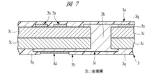
また、図6及び図7は、パッケージ基板3のスルーホール3e内に孔埋め材を充填する構造の例を示すものであり、例えば、図6に示すパッケージ基板3では、スルーホール3eの孔埋め材として、ソルダレジスト等の絶縁膜3iを充填している。前記孔埋め材としてソルダレジスト等の絶縁膜3iを充填することにより、基板のコスト上昇を抑えることができる。
6 and 7 show an example of a structure in which a hole filling material is filled in the through
一方、図7に示す変形例のパッケージ基板3では、スルーホール3eの孔埋め材として、銅合金等の金属膜3hが充填されている。前記孔埋め材として、スルーホール3e内に金属膜3hが埋め込まれていることにより、スルーホール3e内にボイドが形成されることを阻止できる。更には、パッケージ基板3の主面3a及び裏面3bに形成された配線3nと一体形成することが可能であるため、機械的強度を向上することができる。その結果、放熱性も向上させることができるだけでなく、仮に剥離(クラック)がパッケージ基板3の最外周に形成されたランド部(第1ランド部)3dを通過してスルーホール3eにまで到達したとしても断線不良を抑制することができ、CSP7の信頼性を向上させることができる。
On the other hand, in the
次に、本実施の形態1のCSP7の製造方法を、図8〜図10に示す製造プロセスフロー図を用いて説明する。
Next, the manufacturing method of CSP7 of this
まず、図8のステップS1に示す基板準備を行う。ここでは、複数のパッケージ基板3を形成する領域が区画配置された多数個取り基板9を準備する。なお、パッケージ基板3を形成する領域では、最外周に配置されたランド部(第1ランド部)3dと電気的に接続されるスルーホール3eが、ランド部(第1ランド部)3dよりパッケージ基板3を形成する領域の中心側(内側)に形成されている基板を準備する。
First, substrate preparation shown in step S1 of FIG. 8 is performed. Here, a
その後、ステップS2に示すダイボンディングを行って多数個取り基板9上に図3に示す接着剤2を介して半導体チップ1を固着する。その際、パッケージ基板3を形成する領域の周縁部のボンディング用端子3p列の内側に半導体チップ1を搭載する。
Thereafter, die bonding shown in step S2 is performed, and the
その後、ステップS3に示すワイヤボンディングを行う。ここでは、図3に示すように、半導体チップ1の主面1aのパッド1cと、これに対応する多数個取り基板9のパッケージ基板3のワイヤ接合部であるボンディング用端子3pとを金線等の導電性のワイヤ4によって電気的に接続する。
Thereafter, wire bonding shown in step S3 is performed. Here, as shown in FIG. 3, a
その後、ステップS4に示す樹脂モールドを行う。ここでは、多数個取り基板9上において、複数の半導体チップ1や複数のワイヤ4を樹脂成形金型15の1つのキャビティ15aで一括して覆って樹脂封止し、これによって一括封止体5を形成する。なお、一括封止体5を形成する封止用樹脂は、例えば、熱硬化性のエポキシ樹脂等である。
Thereafter, resin molding shown in step S4 is performed. Here, on the
その後、図9のステップS5に示すボールマウントを行って図3に示すようにパッケージ基板3の裏面3bの各ランド部3dに半田ボール8を接続する。
Thereafter, ball mounting shown in step S5 of FIG. 9 is performed, and the
その後、ステップS6に示すマークを行う。ここではレーザマーキング法等でマーキング10を行って一括封止体5にマークを付す。なお、マーキング10は、例えば、インクマーキング法などで行ってもよい。
Then, the mark shown in step S6 is performed. Here, the marking 10 is performed by a laser marking method or the like to mark the
その後、ステップS7に示す個片化を行う。ここでは、一括封止体5の表面にダイシングテープ12を貼り、ダイシングテープ12で固定した状態でダイシングブレード11によって切断して各CSP7に個片化する。
Thereafter, individualization shown in step S7 is performed. Here, the dicing
これにより、ステップS8に示すようにCSP7の組み立てを完了して製品完成となる。
Thereby, as shown in step S8, the assembly of the
なお、図10は樹脂モールド後の組み立ての変形例を示す製造プロセスフロー図である。 FIG. 10 is a manufacturing process flow diagram showing a modified example of assembly after resin molding.
図10に示す変形例は、マークを行った後にボールマウントを行うものである。 In the modification shown in FIG. 10, ball mounting is performed after marking.
ボールマウントの工程は、パッケージ基板3のランド部3dに半田を塗布した後、リフロー処理により半田ボール8を形成する。このため、ボールマウントの工程においても、このリフロー処理によりパッケージ基板3が更に反る問題が生じる。マークの工程では、レーザマーキング法などでマーキングを行うが、パッケージ基板3が反った状態では、一括封止体5の表面に垂直にレーザを照射することが困難となるため、一括封止体5の表面にマークが付されないというマーキング不良が発生する。
In the ball mounting process, solder is applied to the
そこで、図10に示す変形例は、パッケージ基板3が反る要因の一つである半田ボール8形成時のリフロー処理を行う前に、先にマークの工程を行うものである。これにより、マーキング不良を抑制することができる。
Therefore, in the modification shown in FIG. 10, the mark process is first performed before the reflow process at the time of forming the
(実施の形態2)
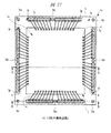
図11は本発明の実施の形態2の半導体装置の構造の一例を封止体を透過して示す平面図、図12は図11に示すA−A線に沿って切断した断面の構造を示す断面図、図13は図12に示すB部の構造を示す拡大部分断面図である。また、図14は図11に示す半導体装置に組み込まれる配線基板の主面側の導体パターンの一例を示す平面図、図15は図14に示す配線基板の裏面側の導体パターンの一例を示す裏面図、図16は図14に示すC−C線に沿って切断した断面の構造を示す拡大部分断面図である。
(Embodiment 2)
FIG. 11 is a plan view showing an example of the structure of the semiconductor device according to the second embodiment of the present invention through a sealing body, and FIG. 12 shows the structure of a cross section taken along the line AA shown in FIG. FIG. 13 is an enlarged partial sectional view showing a structure of a B portion shown in FIG. 14 is a plan view showing an example of a conductor pattern on the main surface side of the wiring board incorporated in the semiconductor device shown in FIG. 11, and FIG. 15 is a back surface showing an example of the conductor pattern on the back side of the wiring board shown in FIG. 16 and 16 are enlarged partial cross-sectional views showing the structure of a cross section cut along the line CC shown in FIG.
図11〜図13に示す本実施の形態2の半導体装置は、実施の形態1のCSP7と同様に、配線基板上に半導体チップ1が搭載された樹脂封止型の小型のCSP13である。
The semiconductor device of the second embodiment shown in FIGS. 11 to 13 is a resin-sealed small-
本実施の形態2のCSP13では、パッケージ基板3の裏面3bの複数のランド部3dにおいて、図15に示すように最外周に配置されたランド部(第1ランド部)3dと電気的に接続されるスルーホール3eは、ランド部(第1ランド部)3dよりパッケージ基板3の中心側に形成されている。さらに、これに加えて複数のスルーホール(第1貫通孔)3eより外側に複数のダミースルーホール(第2貫通孔)3mが形成されており、本実施の形態2では、パッケージ基板3の4つの角部付近にダミースルーホール3mが形成されている。詳細には、パッケージ基板3において、複数のダミースルーホール(第2貫通孔)3mは、複数のスルーホール(第1貫通孔)3e及び複数のランド部3dより外側に形成されており、さらに、第1方向に形成された複数のボンディング用端子3pの配列延長線と第1方向と交差する第2方向に形成された複数のボンディング用端子3pの配列延長線との交点付近にダミースルーホール3mが形成されている。
In the
すなわち、最外周に配置されたランド部(第1ランド部)3dと電気的に接続されるスルーホール(第1貫通孔)3eが、ランド部(第1ランド部)3dより内側に形成されており、さらにパッケージ基板3の4つの角部付近にダミースルーホール(第2貫通孔)3mが形成されている。
That is, a through hole (first through hole) 3e that is electrically connected to the land portion (first land portion) 3d disposed on the outermost periphery is formed inside the land portion (first land portion) 3d. Further, dummy through holes (second through holes) 3 m are formed in the vicinity of the four corners of the
なお、ダミースルーホール3mは、図14〜図16に示すように、ランド部3dやスルーホール3e、さらにボンディング用端子3p等の他の導体パターンと接続していないノンコネクトホールである。ダミースルーホール3mは、パッケージ基板3の周縁部に形成されるものであるが、特に応力が集中し易い角部に形成することが好ましい。上記した剥離(コアクラック)はパッケージ基板3の外周から進展するが、外周の中でも特にパッケージ基板3の中心から最も遠い箇所、すなわち角部付近に応力が集中し易いためである。
As shown in FIGS. 14 to 16, the dummy through
また、CSP13は、CSP7と同様に、小型の半導体パッケージであり、パッケージ基板3は、半導体チップ1より僅かに大きい程度ある。そこで、本実施の形態2のCSP13のように、最外周に配置されたランド部3dと電気的に接続されるスルーホール3eを、ランド部3dより内側に形成することにより、周縁部に形成するダミースルーホール3mとスルーホール3eとが同列配置になることを避けられる。つまり、最外周に配置されたランド部3dと電気的に接続されるスルーホール3eを、ランド部3dより内側に形成することにより、パッケージ基板3が半導体チップ1より僅かに大きなCSP13であってもパッケージ基板3の周縁部にダミースルーホール3mを配置することが可能になる。
The
ただし、半導体チップ1とパッケージ基板3の大きさは、極めて近いため、パッケージ基板3の角部を含む周縁部にダミースルーホール3mを形成した場合、これらダミースルーホール3mの更に外側に放熱用ビア等の他の貫通孔を形成するスペースは無い。
However, since the sizes of the
本実施の形態2のCSP13によれば、最外周に配置されたランド部(第1ランド部)3dと電気的に接続されるスルーホール(第1貫通孔)3eが、ランド部3dより内側に形成され、さらにパッケージ基板3の周縁部にダミースルーホール(第2貫通孔)3mが形成されていることにより、温度サイクル試験等でパッケージ基板3の外周から剥離が生じてもダミースルーホール3mによって剥離の進展を抑制することができる。さらに、剥離が内側に進展したとしても最外周のランド部3dでクラックの進展を抑制することができる。
According to the
これにより、実施の形態1に比べスルーホール3eにおける断線の発生をさらに低減することができ、CSP13の信頼性の向上をさらに図ることができる。
Thereby, the occurrence of disconnection in the through
なお、ダミースルーホール3m内に充填する孔埋め材としては、実施の形態1と同様に、ソルダレジスト等の絶縁膜3iを充填してもよいし、または、銅合金等の金属膜3hを充填してもよい。ただし、ダミースルーホール3m内に金属膜3hを充填する場合、ダミースルーホール3mに導体膜を形成するとともに前記導体膜に繋がる給電線3rが接続されている必要がある。
In addition, as the hole filling material to be filled in the dummy through
また、本実施の形態2のCSP13は、少なくともスルーホール3eの外側に複数のダミースルーホール3mが設けられていればよく、最外周に配置されたランド部3dと電気的に接続されるスルーホール3eが、必ずしもランド部3dより内側に形成されていなくてもよい。
The
本実施の形態2のCSP13のその他の構造と、CSP13によって得られるその他の効果については、CSP7と同様であるため、その重複説明は省略する。
Since the other structure of the
(実施の形態3)
図17は本発明の実施の形態3の半導体装置の構造の一例を封止体を透過して示す平面図、図18は図17に示すA−A線に沿って切断した断面の構造を示す断面図、図19は図17に示すB−B線に沿って切断した断面の構造を示す断面図、図20は図18に示すC部の構造を示す拡大部分断面図である。さらに、図21は図17に示す半導体装置に組み込まれる配線基板の主面側の導体パターンの一例を示す平面図、図22は図21に示す配線基板の裏面側の導体パターンの一例を示す裏面図である。
(Embodiment 3)
FIG. 17 is a plan view showing an example of the structure of the semiconductor device according to the third embodiment of the present invention through a sealing body, and FIG. 18 shows the structure of a cross section taken along the line AA shown in FIG. FIG. 19 is a cross-sectional view showing the structure of a cross section cut along the line BB shown in FIG. 17, and FIG. 20 is an enlarged partial cross-sectional view showing the structure of part C shown in FIG. 21 is a plan view showing an example of a conductor pattern on the main surface side of the wiring board incorporated in the semiconductor device shown in FIG. 17, and FIG. 22 is a back surface showing an example of the conductor pattern on the back side of the wiring board shown in FIG. FIG.
図17〜図20に示す本実施の形態3の半導体装置は、実施の形態1のCSP7と同様に、配線基板上に半導体チップ1が搭載された樹脂封止型の小型のCSP14である。
The semiconductor device according to the third embodiment shown in FIGS. 17 to 20 is a resin-sealed small-
本実施の形態3のCSP14では、パッケージ基板3の裏面3bの複数のランド部3dにおいて、図22に示すように最外周に配置されたランド部3dと電気的に接続されるスルーホール3eは、ランド部3dよりパッケージ基板3の中心側に形成されている。さらに、これに加えて複数のスルーホール(第1貫通孔)3eより外側に複数のダミースルーホール(第2貫通孔)3mが形成されており、本実施の形態2では、図21に示すようにパッケージ基板3の4つの角部付近(第1方向に形成された複数のボンディング用端子3pの配列延長線と第1方向と交差する第2方向に形成された複数のボンディング用端子3pの配列延長線との交点付近)と、ボンディング用端子3pの列間とにダミースルーホール3mが形成されている。
In the
また、CSP14では、パッケージ基板3のスルーホール3eとダミースルーホール3mそれぞれが、レーザ加工によって形成されている。レーザ加工では、基板に貫通孔を形成する場合、ドリルで貫通孔を形成する場合に比較して貫通孔の孔径を非常に小さくすることができる。さらに、図20に示すように、貫通孔におけるレーザの進行方向の前側の開口部3jと後ろ側の開口部3kとではその大きさが異なる。
Further, in the
レーザ加工においては、レーザの中心の強度が最も高く、中心から離れて外周に向かうにつれてレーザの強度が低くなる。したがって、レーザの中心は強度が高いことにより、基板を貫通するが、これに比べて外周は強度が低いため貫通までは至らず、結果として図20に示すように、スルーホール3eにおける基板の厚さ方向に沿った断面の形状は、台形(正台形)になる。
In laser processing, the intensity of the center of the laser is the highest, and the intensity of the laser decreases as it moves away from the center toward the outer periphery. Therefore, the center of the laser penetrates the substrate due to its high strength, but the outer periphery has a lower strength than that, so the penetration does not reach. As a result, as shown in FIG. 20, the thickness of the substrate in the through
図20に示すパッケージ基板3の場合には、レーザの進行方向の前側の開口部(レーザ照射面とは反対側に形成されるスルーホール3eの開口部)3jは、その形状が、例えば、直径0.02〜0.03mm程度の円形であり、一方、レーザの進行方向の後ろ側の開口部(レーザ照射面に形成されるスルーホール3eの開口部)3kは、その形状が、例えば、直径0.05〜0.07mm程度の円形である。
In the case of the
なお、ダミースルーホール3mを形成する際に、レーザ加工の方向は主面側からでも裏面側からでもどちらでもよい。
When forming the dummy through
また、CSP14のパッケージ基板3では、図21に示すように、各ボンディング用端子3pの外側に図4に示すような給電線3rが形成されていない。すなわち、CSP14のパッケージ基板3は、無電解メッキ処理等によって各導体パターンのメッキを形成したものである。
Further, in the
また、CSP14は、CSP7と同様に、小型の半導体パッケージであり、パッケージ基板3は、半導体チップ1より僅かに大きい程度ある。したがって、パッケージ基板3の周縁部にダミースルーホール3mを形成するスペースを確保するのが困難である。そこで、本実施の形態3のCSP14では、ボンディング用端子3pの列間にダミースルーホール3mを配置するにあたり、全てのスルーホール3eをレーザ加工によって形成して貫通孔の孔径を非常に小さくすることで、スペースを確保している。すなわち、最外周に配置されたランド部3dと電気的に接続するスルーホール3eを、ランド部3dよりパッケージ基板3の中心側に形成できるとともに、周縁部にダミースルーホール3mを形成することができる。
The
特に、ピン数の増加によってダミースルーホール3mの形成がスペース的に困難な場合、スルーホール3eやダミースルーホール3mをレーザ加工によって形成することに相対的に小径の穴(ドリル加工で開けた穴よりも小さい穴)を開けることが可能となり、ダミースルーホール3mを形成するためのスペースの確保が容易になる。例えば、多ピン化に対応させてボンディング用端子3pの列間に形成する際のダミースルーホール3mは、図21に示すように、可能な限り孔径が小さな方が好ましい。
In particular, when the formation of the dummy through
このようにCSP14においても、実施の形態2のCSP13と同様に、最外周に配置されたランド部3dと電気的に接続されるスルーホール3eが、ランド部3dより内側に形成され、さらに4つの角部を含むパッケージ基板3の周縁部にダミースルーホール3mが形成されていることにより、温度サイクル試験等でパッケージ基板3の外周からクラックが生じてもダミースルーホール3mによってクラックの進展を抑制することができる。さらに、クラックが内側に進展したとしても最外周のランド部3dでクラックの進展を抑制することができる。
As described above, in the
これにより、スルーホール3eにおける断線の発生をさらに低減することができ、CSP14の信頼性の向上をさらに図ることができる。
Thereby, generation | occurrence | production of the disconnection in the through
なお、ダミースルーホール3m内に充填する孔埋め材としては、実施の形態1と同様に、ソルダレジスト等の絶縁膜3iを充填してもよいし、または、銅合金等の金属膜3hを充填してもよい。ただし、ダミースルーホール3m内に金属膜3hを充填する場合、ダミースルーホール3mに導体膜を形成するとともに前記導体膜に繋がる給電線3rが接続されている必要がある。
In addition, as the hole filling material to be filled in the dummy through
本実施の形態3のCSP14のその他の構造と、CSP14によって得られるその他の効果については、実施の形態2のCSP13と同様であるため、その重複説明は省略する。
Since the other structure of the
以上、本発明者によってなされた発明を発明の実施の形態に基づき具体的に説明したが、本発明は前記発明の実施の形態に限定されるものではなく、その要旨を逸脱しない範囲で種々変更可能であることは言うまでもない。 As mentioned above, the invention made by the present inventor has been specifically described based on the embodiments of the invention. However, the present invention is not limited to the embodiments of the invention, and various modifications can be made without departing from the scope of the invention. It goes without saying that it is possible.
例えば、前記実施の形態1,2及び3では、パッケージ基板3においてコア材3cが2層の場合を説明したが、コア材3cは2層以上の複数の層が貼り合わされて形成されていれば何層であってもよい。
For example, in the first, second and third embodiments, the case where the
本発明は、配線基板を有した電子装置に好適である。 The present invention is suitable for an electronic device having a wiring board.
1 半導体チップ
1a 主面
1b 裏面
1c パッド(電極)
2 接着剤
3 パッケージ基板(配線基板)
3a 主面
3b 裏面
3c コア材
3d ランド部
3e スルーホール(第1貫通孔)
3f 開口窓
3g メッキ膜
3h 金属膜
3i 絶縁膜
3j,3k 開口部
3m ダミースルーホール(第2貫通孔)
3n 配線
3p ボンディング用端子(ワイヤ接合部)
3q ソルダレジスト膜
3r 給電線
4 ワイヤ
5 一括封止体
6 樹脂体
7 CSP(半導体装置)
8 半田ボール(外部端子)
9 多数個取り基板
10 マーキング
11 ダイシングブレード
12 ダイシングテープ
13,14 CSP(半導体装置)
15 樹脂成形金型
15a キャビティ
DESCRIPTION OF
2 Adhesive 3 Package board (wiring board)
3q Solder resist
8 Solder balls (external terminals)
9
15
Claims (7)
前記配線基板の主面上に搭載された半導体チップと、
前記半導体チップの複数の電極と前記配線基板の主面に形成された前記複数のワイヤ接合部とをそれぞれ電気的に接続する複数のワイヤと、
前記半導体チップ及び前記複数のワイヤを封止する樹脂体と、
前記複数のランド部上に形成された複数の外部端子と、
を有し、
前記複数の第1貫通孔のうち、前記複数のランド部において最外周に配置された第1ランド部と電気的に接続されるメッキ膜が形成された貫通孔は、前記第1ランド部より前記配線基板の中心側に形成されており、
前記複数の第2貫通孔は、前記複数の第1貫通孔および前記複数のランド部より前記配線基板の外側にそれぞれ形成されており、かつ、前記複数のワイヤ接合部のうちの前記配線基板の第1辺と並ぶ第1方向に沿って形成された複数の第1ワイヤ接合部の配列延長線と、前記複数のワイヤ接合部のうちの前記配線基板の前記第1辺と交差する第2辺と並ぶ第2方向に沿って形成された複数の第2ワイヤ接合部の配列延長線との交点部にそれぞれ形成されており、
前記複数の第2貫通孔のそれぞれは、前記複数のワイヤ接合部、前記複数のランド部、および前記複数の第1貫通孔のそれぞれの内壁に形成された前記メッキ膜と接続されていないことを特徴とする半導体装置。 A main surface in which the planar shape is a square shape , a planar shape is in a square shape, and a back surface opposite to the main surface, a plurality of wire joints formed on the main surface, and a plurality of wires formed on the back surface A plurality of first through holes formed between the land portion, the main surface and the back surface, a plurality of second through holes formed between the main surface and the back surface, and the plurality of first through holes. A wiring board having a plating film formed on each inner wall and electrically connecting the plurality of wire bonding portions and the plurality of land portions;
A semiconductor chip mounted on the main surface of the wiring board;
A plurality of wires that electrically connect the plurality of electrodes of the semiconductor chip and the plurality of wire joints formed on the main surface of the wiring board, respectively;
A resin body for sealing the semiconductor chip and the plurality of wires;
A plurality of external terminals formed on the plurality of land portions;
Have
Among the plurality of first through holes, the plurality of transmural hole plating film is formed to be the first land portion electrically connected disposed outermost in the land portion, from the first land portion It is formed on the center side of the wiring board ,
The plurality of second through holes are formed outside the wiring board from the plurality of first through holes and the plurality of land parts, respectively, and the wiring board of the plurality of wire joints is formed. An array extension line of a plurality of first wire bonding portions formed along a first direction aligned with the first side, and a second side that intersects the first side of the wiring board among the plurality of wire bonding portions. Are formed at intersections with the array extension lines of the plurality of second wire joints formed along the second direction,
Each of the plurality of second through holes is not connected to the plating film formed on the inner wall of each of the plurality of wire joint portions, the plurality of land portions, and the plurality of first through holes. A featured semiconductor device.
Priority Applications (1)
| Application Number | Priority Date | Filing Date | Title |
|---|---|---|---|
| JP2006027830A JP4825529B2 (en) | 2006-02-06 | 2006-02-06 | Semiconductor device |
Applications Claiming Priority (1)
| Application Number | Priority Date | Filing Date | Title |
|---|---|---|---|
| JP2006027830A JP4825529B2 (en) | 2006-02-06 | 2006-02-06 | Semiconductor device |
Publications (3)
| Publication Number | Publication Date |
|---|---|
| JP2007208153A JP2007208153A (en) | 2007-08-16 |
| JP2007208153A5 JP2007208153A5 (en) | 2009-03-19 |
| JP4825529B2 true JP4825529B2 (en) | 2011-11-30 |
Family
ID=38487328
Family Applications (1)
| Application Number | Title | Priority Date | Filing Date |
|---|---|---|---|
| JP2006027830A Expired - Fee Related JP4825529B2 (en) | 2006-02-06 | 2006-02-06 | Semiconductor device |
Country Status (1)
| Country | Link |
|---|---|
| JP (1) | JP4825529B2 (en) |
Families Citing this family (4)
| Publication number | Priority date | Publication date | Assignee | Title |
|---|---|---|---|---|
| JP4998338B2 (en) * | 2008-03-11 | 2012-08-15 | 富士通セミコンダクター株式会社 | Semiconductor device and circuit board |
| JP5223571B2 (en) | 2008-09-30 | 2013-06-26 | 富士通株式会社 | Semiconductor device, substrate design method, substrate design apparatus |
| JP5557439B2 (en) | 2008-10-24 | 2014-07-23 | ピーエスフォー ルクスコ エスエイアールエル | Semiconductor device and manufacturing method thereof |
| US9601818B2 (en) | 2013-06-25 | 2017-03-21 | Panasonic Intellectual Property Management Co., Ltd. | Microwave circuit |
Family Cites Families (6)
| Publication number | Priority date | Publication date | Assignee | Title |
|---|---|---|---|---|
| JP3685347B2 (en) * | 1995-12-30 | 2005-08-17 | ソニー株式会社 | Semiconductor device |
| JPH113954A (en) * | 1997-06-11 | 1999-01-06 | Hitachi Cable Ltd | Wiring board for mounting semiconductor element and semiconductor device |
| JP2002118204A (en) * | 1999-11-17 | 2002-04-19 | Sumitomo Bakelite Co Ltd | Semiconductor device, semiconductor mounting substrate and method of manufacturing the same |
| JP3936681B2 (en) * | 2003-08-25 | 2007-06-27 | 沖電気工業株式会社 | Semiconductor device |
| JP4308608B2 (en) * | 2003-08-28 | 2009-08-05 | 株式会社ルネサステクノロジ | Semiconductor device |
| JP4273895B2 (en) * | 2003-09-24 | 2009-06-03 | 日立化成工業株式会社 | Manufacturing method of package substrate for mounting semiconductor device |
-
2006
- 2006-02-06 JP JP2006027830A patent/JP4825529B2/en not_active Expired - Fee Related
Also Published As
| Publication number | Publication date |
|---|---|
| JP2007208153A (en) | 2007-08-16 |
Similar Documents
| Publication | Publication Date | Title |
|---|---|---|
| US8159057B2 (en) | Semiconductor device and manufacturing method therefor | |
| CN102456677B (en) | Packaging structure for ball grid array and manufacturing method for same | |
| US7829987B2 (en) | Carrier structure embedded with semiconductor chips and method for manufacturing the same | |
| US7566969B2 (en) | Semiconductor device with improved arrangement of a through-hole in a wiring substrate | |
| US10304767B2 (en) | Semiconductor device | |
| US10134665B2 (en) | Semiconductor device | |
| JP5501562B2 (en) | Semiconductor device | |
| KR20050009036A (en) | Stack package and manufacturing method thereof | |
| US7745260B2 (en) | Method of forming semiconductor package | |
| JP2007335581A (en) | Manufacturing method of semiconductor device | |
| JP2009043793A (en) | Semiconductor device and method for manufacturing the same | |
| JP2020025019A (en) | Semiconductor device | |
| JP4825529B2 (en) | Semiconductor device | |
| JP2007235009A (en) | Semiconductor device | |
| JP4494249B2 (en) | Semiconductor device | |
| JP2009182004A (en) | Semiconductor device | |
| JP5298714B2 (en) | Manufacturing method of semiconductor device | |
| JP4232613B2 (en) | Manufacturing method of semiconductor device | |
| JP2009099816A (en) | Semiconductor device, method for manufacturing the same, and method for mounting the semiconductor device | |
| JP4614818B2 (en) | Semiconductor device and manufacturing method thereof | |
| JP2011061055A (en) | Method of manufacturing semiconductor device | |
| JP3920657B2 (en) | Manufacturing method of resin-encapsulated semiconductor device | |
| JP4917979B2 (en) | Semiconductor device and manufacturing method thereof | |
| JP2006344827A (en) | Manufacturing method of semiconductor device | |
| JPH10209321A (en) | Semiconductor integrated circuit device |
Legal Events
| Date | Code | Title | Description |
|---|---|---|---|
| A521 | Request for written amendment filed |
Free format text: JAPANESE INTERMEDIATE CODE: A523 Effective date: 20090202 |
|
| A621 | Written request for application examination |
Free format text: JAPANESE INTERMEDIATE CODE: A621 Effective date: 20090202 |
|
| A977 | Report on retrieval |
Free format text: JAPANESE INTERMEDIATE CODE: A971007 Effective date: 20090421 |
|
| A711 | Notification of change in applicant |
Free format text: JAPANESE INTERMEDIATE CODE: A712 Effective date: 20100528 |
|
| A131 | Notification of reasons for refusal |
Free format text: JAPANESE INTERMEDIATE CODE: A131 Effective date: 20110531 |
|
| A521 | Request for written amendment filed |
Free format text: JAPANESE INTERMEDIATE CODE: A523 Effective date: 20110729 |
|
| TRDD | Decision of grant or rejection written | ||
| A01 | Written decision to grant a patent or to grant a registration (utility model) |
Free format text: JAPANESE INTERMEDIATE CODE: A01 Effective date: 20110816 |
|
| A01 | Written decision to grant a patent or to grant a registration (utility model) |
Free format text: JAPANESE INTERMEDIATE CODE: A01 |
|
| A61 | First payment of annual fees (during grant procedure) |
Free format text: JAPANESE INTERMEDIATE CODE: A61 Effective date: 20110912 |
|
| R150 | Certificate of patent or registration of utility model |
Free format text: JAPANESE INTERMEDIATE CODE: R150 |
|
| FPAY | Renewal fee payment (event date is renewal date of database) |
Free format text: PAYMENT UNTIL: 20140916 Year of fee payment: 3 |
|
| S531 | Written request for registration of change of domicile |
Free format text: JAPANESE INTERMEDIATE CODE: R313531 |
|
| R350 | Written notification of registration of transfer |
Free format text: JAPANESE INTERMEDIATE CODE: R350 |
|
| LAPS | Cancellation because of no payment of annual fees |