JP4595427B2 - Power converter - Google Patents
Power converter Download PDFInfo
- Publication number
- JP4595427B2 JP4595427B2 JP2004221345A JP2004221345A JP4595427B2 JP 4595427 B2 JP4595427 B2 JP 4595427B2 JP 2004221345 A JP2004221345 A JP 2004221345A JP 2004221345 A JP2004221345 A JP 2004221345A JP 4595427 B2 JP4595427 B2 JP 4595427B2
- Authority
- JP
- Japan
- Prior art keywords
- capacitor
- power supply
- capacity
- inverter
- small
- Prior art date
- Legal status (The legal status is an assumption and is not a legal conclusion. Google has not performed a legal analysis and makes no representation as to the accuracy of the status listed.)
- Expired - Fee Related
Links
Images


Landscapes
- Air Conditioning Control Device (AREA)
- Inverter Devices (AREA)
Description
本発明は、電力変換装置におよびそれを用いたモータ駆動用インバータ制御装置及び空
気調和機に関するものである。
The present invention relates to a power conversion device and a motor drive inverter control device and an air conditioner using the power conversion device.
従来、電力変換装置における制御電源とゲート駆動回路が提案されている(例えば、非特許文献1参照)。 Conventionally, a control power supply and a gate drive circuit in a power conversion device have been proposed (for example, see Non-Patent Document 1).
図4は、前記非特許文献1に記載された従来の制御電源とゲート駆動回路の構成を示すブロック図である。図4に示すように、交流電源を入力とし、ダイオードブリッジ6で構成される整流回路と、整流回路の出力である直流電力から交流電力に変換するインバータ10を備えている。インバータ10の直流母線間には、平滑回路としてのDCリンクコンデンサ21が接続されている。このDCリンクコンデンサ21が入力側に接続されたスイッチング制御電源部14は、トランス23およびトランジスタ22などのスイッチング素子で構成され、インバータ10の駆動電源24およびマイコン26などの制御手段を動作させるための制御電源25を供給するものである。上記構成において、一般的にスイッチング制御電源部14の入力側のDCリンクコンデンサ21は大容量であるので、スイッチング制御電源部14の入力電圧は一定であるので、スイッチング制御電源部14は安定した動作を行うことができ、一定の制御電源25および駆動電源24を供給することができる。
FIG. 4 is a block diagram showing the configuration of the conventional control power source and gate drive circuit described in Non-Patent
図5は、従来のインバータ装置およびインバータシステムを示す図である。
図5に示すインバータ装置は、直流主電源ライン50を通じて供給された直流電力を平滑する主平滑コンデンサ51(第1コンデンサ)と、主平滑コンデンサ51が平滑した直流電力を与えられ、交流電力に変換するインバータ主回路52と、インバータ主回路52を制御するインバータ制御部53とを備えている。また、このインバータ装置は、直流主電源ライン50の正側ラインが、ヒューズ54、順接続されたダイオード55(逆流防止ダイオード)及び抵抗器56を経てDC/DCスイッチング電源部57の負側端子に接続され、DC/DCスイッチング電源部57の両端子間に、平滑コンデンサ58(第2コンデンサ)が接続されている。DC/DCスイッチング電源部57は、平滑コンデンサ58が平滑した直流電力を与えられ、スイッチング制御により所定の直流電圧に変換して、インバータ制御部53に与える。
FIG. 5 is a diagram illustrating a conventional inverter device and inverter system.
The inverter device shown in FIG. 5 is provided with a main smoothing capacitor 51 (first capacitor) that smoothes the DC power supplied through the DC main
上記、構成によれば、逆流防止ダイオード55は、第2コンデンサからの電流の逆流を防止するので、瞬停等による電源低下に対しても、制御電源を安定して確保できる。
しかしながら、前記従来の構成では、容量の大きなDCリンクコンデンサ21を有しており、装置の大型化やコストUPを招いている。装置の小型・軽量・低コスト化を実現するために、DCリンクコンデンサ21を小容量にすることが考えられるが、DCリンクコンデンサ21が小容量であると、インバータ10の出力に接続されている負荷が大きい場合、図3に示すように、インバータ10の直流母線間電圧は交流電源周波数の2倍の周波数で大きく脈動し、ゼロとなる場合がある。インバータ10の直流母線間電圧がゼロとなると、DCリンクコンデンサ21に接続されているスイッチング制御電源部14が動作しなくなり、制御電源25および駆動電源24が出力されず、マイコン26などの制御手段が動作せず、システム全体が停止してしまうという課題があった。
However, the conventional configuration includes the DC link capacitor 21 having a large capacity, which increases the size of the apparatus and increases the cost. In order to reduce the size, weight, and cost of the apparatus, it is conceivable to reduce the capacity of the DC link capacitor 21. If the DC link capacitor 21 has a small capacity, it is connected to the output of the
さらに、前記特許文献1によれば、第2コンデンサの容量は、DC/DCスイッチング電源部57の入力電圧が、瞬停等の場合、ある一定期間減少するので、その電源リプルに対応できる容量で構成されているが、本発明によれば、主平滑コンデンサが小容量であるので、常時、主平滑コンデンサの両端電圧が交流電源周波数の2倍の周波数で脈動するので、安定したスイッチング制御電源を得るのが困難となる課題があった。
Further, according to
本発明の電力変換装置は、上記従来の問題を解決するものであり、小型・軽量・低コストで、インバータの直流母線間電圧が大きく脈動しても安定したスイッチング制御電源部の動作を実現でき、一定の制御電源および駆動電源を供給できる電力変換装置を提供することを目的とする。 The power conversion device of the present invention solves the above-mentioned conventional problems, and is small, light, and low in cost, and can realize stable operation of the switching control power supply even if the DC bus voltage of the inverter pulsates greatly. An object of the present invention is to provide a power converter that can supply a constant control power and drive power.
前記従来の課題を解決するために、本発明の電力変換装置は、交流電源を入力とし、ダイオードブリッジと、ダイオードブリッジの交流入力側または直流出力側に接続される小容量のリアクタで構成される整流回路と、前記整流回路の出力である直流電力から交流電力に変換するインバータとを備え、インバータの直流母線間には、小容量のDCリンクコンデンサを備え、またスイッチング制御電源部の1次回路が電荷を蓄積する1次側コンデンサで構成され、スイッチング制御電源部の出力を制御手段に供給するもので、前記1次側コンデンサと前記インバータの直流母線間に単方向整流手段を備えたものである。 In order to solve the above-described conventional problems, the power conversion device of the present invention includes an AC power supply as an input, and includes a diode bridge and a small capacity reactor connected to the AC input side or DC output side of the diode bridge. A rectifier circuit; and an inverter for converting the direct current power, which is the output of the rectifier circuit, into alternating current power. A small capacity DC link capacitor is provided between the direct current buses of the inverter, and a primary circuit of the switching control power supply unit. Is constituted by a primary side capacitor for accumulating electric charge, and supplies the output of the switching control power supply unit to the control means, and comprises a unidirectional rectifying means between the primary side capacitor and the DC bus of the inverter. is there.
上記の構成によって、小容量DCリンクコンデンサおよび小容量リアクタを用いることにより、小型・軽量・低コストな電力変換装置を実現でき、またインバータの直流母線間電圧が大きく脈動しても安定したスイッチング制御電源部の動作を実現でき、一定な制御電源および駆動電源を出力できる。 With the above configuration, by using a small-capacity DC link capacitor and a small-capacity reactor, a compact, lightweight, and low-cost power converter can be realized, and stable switching control is possible even when the inverter DC bus voltage pulsates greatly. The operation of the power supply unit can be realized, and constant control power and drive power can be output.
本発明の電力変換装置によれば、インバータの直流母線間電圧が大きく脈動しても、安定したスイッチング制御電源部の動作を実現でき、一定な制御電源および駆動電源を供給できる。また、それを用いたモータ駆動用インバータ制御装置及び空気調和機を提供できる。
According to the power conversion device of the present invention, even if the DC bus voltage of the inverter pulsates greatly, stable operation of the switching control power supply unit can be realized, and constant control power and drive power can be supplied. Moreover, the inverter control apparatus for motor drive using the same and an air conditioner can be provided.
第1の発明は、スイッチング制御電源部の1次回路に1次側コンデンサと、前記1次側コンデンサとインバータの直流母線間に単方向整流手段を設け、小容量DCリンクコンデンサと小容量リアクタとの共振周波数(LC共振周波数)を交流電源周波数の40倍よりも大きくなるようにすることで、インバータの直流母線間電圧が大きく脈動しても、安定したスイッチング制御電源部の動作を実現でき、一定な制御電源および駆動電源を供給できる。また、交流電源電流の高調波成分を抑制してIEC規格をクリアすることができる。さらに、1次側コンデンサ容量を、スイッチング制御電源部が停止しないだけ投入することで、スイッチング制御電源部を安定に動作させることができる。 In a first aspect of the present invention, a primary capacitor is provided in a primary circuit of a switching control power supply unit, and a unidirectional rectifier is provided between the primary capacitor and a DC bus of the inverter, and a small-capacity DC link capacitor, a small-capacity reactor, resonance frequency (LC resonance frequency) in larger way to Rukoto than 40 times the AC power source frequency, even if the DC bus voltage of the inverter is increased pulsation, can realize the operation of the stable switching control power unit Constant control power and drive power can be supplied. In addition, the IEC standard can be cleared by suppressing the harmonic component of the AC power supply current. Furthermore, the switching control power supply unit can be stably operated by turning on the primary capacitor capacity so that the switching control power supply unit does not stop.
第2の発明は、特に第1の発明でさらにファンモータに接続されるコンデンサと前記インバータの直流母線間に単方向整流手段を設けることを特徴とするもので、この構成によれば、小型・軽量・低コストな電力変換装置を実現でき、ファンモータに接続されるコンデンサとインバータの直流母線間に単方向整流手段を設けることで、インバータの直流母線間電圧が大きく脈動しても、問題なく使用することができる。 The second invention is characterized in that a unidirectional rectifying means is provided between the capacitor connected to the fan motor and the DC bus of the inverter, particularly according to the first invention. A lightweight and low-cost power conversion device can be realized, and by providing a unidirectional rectifier between the capacitor connected to the fan motor and the DC bus of the inverter, there is no problem even if the voltage between the DC buses of the inverter pulsates greatly. Can be used.
第3の発明は、特に第1の発明でさらに誘導性負荷に接続されるコンデンサと前記イン
バータの直流母線間に単方向整流手段を設けることを特徴とするもので、インバータの直流母線間電圧が大きく脈動しても、問題なく使用することができる。
The third invention is characterized in that a unidirectional rectifying means is provided between the capacitor connected to the inductive load and the DC bus of the inverter, particularly in the first invention. Even if it pulsates greatly, it can be used without problems.
以下、本発明の実施の形態について、図面を参照して説明する。なお、本実施の形態によって本発明が限定されるものではない。 Embodiments of the present invention will be described below with reference to the drawings. Note that the present invention is not limited to the embodiment.
(実施の形態1)
図1は、本発明の第1の実施形態である電力変換装置のシステム構成を示すものである。図1の装置は、交流電源1と、交流電源からの交流を全波整流する4つのダイオード2〜5で形成されたブリッジ整流回路6と、ブリッジ整流回路6の交流入力側に挿入された小容量のリアクタ9と、ブリッジ整流回路6の直流側母線間に接続した極めて小容量のDCリンクコンデンサ7と、ブリッジ整流回路6の出力である直流電力から交流電力に変換するインバータ10とを備えるもので、またスイッチング制御電源部14の1次回路が電荷を蓄積する1次側コンデンサ13で構成され、スイッチング制御電源部14の出力を制御手段16に供給するもので、前記1次側コンデンサ13と前記インバータ10の直流母線間に単方向整流手段12を備えたものである。尚、小容量リアクタ9の設置箇所はブリッジ整流回路6の直流出力端と小容量DCリンクコンデンサ7との間でも構わない。
(Embodiment 1)
FIG. 1 shows a system configuration of a power conversion apparatus according to the first embodiment of the present invention. The apparatus shown in FIG. 1 includes an
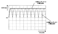
本発明の実施の形態1である電力変換装置において、スイッチング制御電源部14の1次側コンデンサ13と、インバータ10の直流母線間との間にダイオード等の単方向整流手段12を設けることで、インバータ10の直流母線間電圧が1次側コンデンサ13の電圧より高い場合のみ、1次側コンデンサ13へ充電し、インバータ10の直流母線間電圧が1次側コンデンサ13より低くなった場合には1次側コンデンサ13が放電しない構成となるため、図2に示す通り、インバータ10の直流母線間電圧が交流電源周波数の2倍の周波数で大きく脈動しても、スイッチング制御電源部14の入力電圧である1次側コンデンサ13の両端電圧はゼロまで低下することなく、スイッチング制御電源部14が安定した動作を行い、一定の制御電源および駆動電源を供給することができる。図2は図1の小容量DCリンクコンデンサ7と1次側コンデンサ13の両端の電圧波形図である。なお、インバータ10の出力は負荷モータなど負荷が大きいものであるので、負荷が大きいと図2に示す通り、インバータの直流母線間電圧が大きく脈動するが、スイッチング制御電源部14の出力はマイコンなどの制御手段16であるため、負荷が小さく1次側コンデンサ13が小容量であっても、インバータの直流母線間と1次側コンデンサ13との間に単方向整流手段12を設けているので、インバータの直流母線間電圧のように、大きく脈動することはない。なお、1次側コンデンサ13の電圧が、交流電源周波数の2倍の周波数で脈動するので、1次側コンデンサ13は、脈動する電源リプルに対応できるコンデンサ容量が確保されていれば問題ない。
In the power conversion device according to the first embodiment of the present invention, by providing the unidirectional rectifying means 12 such as a diode between the primary side capacitor 13 of the switching control
(実施の形態2)
本発明の第2の実施の形態である電力変換装置について、以下に説明する。詳しくは、前記実施の形態1の小容量DCリンクコンデンサ7および小容量リアクタ9の仕様決定に関する具体的な方法、また前記実施の形態1の1次側コンデンサ13の容量決定方法について以下に説明する。
(Embodiment 2)
The power converter device which is the 2nd Embodiment of this invention is demonstrated below. Specifically, a specific method for determining specifications of the small-capacity DC link capacitor 7 and the small-capacity reactor 9 according to the first embodiment and a method for determining the capacity of the primary capacitor 13 according to the first embodiment will be described below. .
本発明の実施の形態2の電力変換装置では、交流電源電流の高調波成分を抑制してIEC規格をクリアするために、小容量DCリンクコンデンサ7と小容量リアクタ9との共振周波数fLC(LC共振周波数)を交流電源周波数fSの40倍よりも大きくなるようにする。 In the power conversion device according to the second embodiment of the present invention, the resonance frequency fLC (LC) of the small-capacity DC link capacitor 7 and the small-capacity reactor 9 is used to clear the IEC standard by suppressing the harmonic component of the AC power supply current. Resonance frequency) is set to be larger than 40 times the AC power supply frequency fS.
ここで、小容量DCリンクコンデンサ7の容量をC[F]、小容量リアクタ9のインダクタンス値をL[H]とすると、LC共振周波数fLCは数1のように表される。 Here, assuming that the capacity of the small-capacity DC link capacitor 7 is C [F] and the inductance value of the small-capacity reactor 9 is L [H], the LC resonance frequency fLC is expressed as follows.

即ち、fLC>40fSを満たすように小容量DCリンクコンデンサ7と小容量リアクタ9の組み合わせを決定するものである。(IEC規格では交流電源電流の高調波成分において第40次高調波まで規定されているため)以上により、小容量DCリンクコンデンサ7および小容量リアクタ9の組み合わせを決定することで、交流電源電流の高調波成分を抑制して、IEC規格をクリアすることが可能となる。 That is, the combination of the small-capacity DC link capacitor 7 and the small-capacity reactor 9 is determined so as to satisfy fLC> 40 fS. By the above, the combination of the small-capacity DC link capacitor 7 and the small-capacity reactor 9 can be determined by determining the combination of the small-capacity DC link capacitor 7 and the small-capacity reactor 9. It is possible to suppress harmonic components and clear the IEC standard.
次に、実施の形態1に示してある通り、インバータの直流母線間に接続されているDCリンクコンデンサ7が小容量であると、インバータの直流母線間電圧は電源周波数の2倍の周波数で大きく脈動してしまう。これを、インバータの直流母線間とスイッチング制御電源部14の1次側コンデンサ13との間に単方向整流手段12を設けることで、小容量DCリンクコンデンサ7の容量に影響されることなくスイッチング制御電源部14に入力電圧を供給することができる。スイッチング制御電源部14が停止しないだけ1次側コンデンサ13を投入することで、スイッチング制御電源部14の安定した動作が望め、一定の制御電源および駆動電源を供給することができる。なお、スイッチング制御電源部14の出力側はマイコンなどの制御手段16に接続されており、負荷が小さいので、スイッチング制御電源部14の入力側に接続された1次側コンデンサ13は小容量で済むことから、装置の小型・軽量化も図れる。このときの諸元としては、小容量リアクタ6のインダクタンス値は0.5mH、小容量DCリンクコンデンサ7の容量は10μF、交流電源は220V(50Hz)、また1次側コンデンサの容量13は10μFである。
Next, as shown in the first embodiment, when the DC link capacitor 7 connected between the DC buses of the inverter has a small capacity, the voltage between the DC buses of the inverter increases at a frequency twice the power supply frequency. It pulsates. By providing the unidirectional rectifying means 12 between the DC buses of the inverter and the primary side capacitor 13 of the switching control
(実施の形態3)
本発明の第3の実施の形態である電力変換装置について、以下に説明する。
(Embodiment 3)
The power converter device which is the 3rd Embodiment of this invention is demonstrated below.
本発明の実施の形態3の電力変換装置は、前記実施の形態1の小容量DCリンクコンデンサ7および前記実施の形態1の1次側コンデンサ13をフィルムコンデンサもしくはセラミックコンデンサにすることである。インバータの直流母線間電圧は電源周波数の2倍の周期で大きく脈動するため、リプル電流も大きく、リプル許容電流が小さい電解コンデンサは使用できない。そこで、リプル電流を気にすることなく使用することができるフィルムコンデンサを用いる。なお、前記小容量コンデンサ7は容量が小さいためフィルムコンデンサを用いることができる。次に、スイッチング制御電源部14の1次側コンデンサ13の容量は、実施の形態2に示した通り、スイッチング制御電源部14が停止しないだけ投入することから、1次側コンデンサ13も小容量であるため、リプル電流が大きくなる傾向にある。従って、上記小容量コンデンサ7と同じく、1次側コンデンサ13にもフィルムコンデンサを用いることで、スイッチング制御電源部14の入力電圧にリプルが発生しても問題ない。また、1次側コンデンサ13が大容量タイプのセラミックコンデンサであっても同様の効果を得ることができる。
In the power conversion device according to the third embodiment of the present invention, the small-capacity DC link capacitor 7 according to the first embodiment and the primary side capacitor 13 according to the first embodiment are film capacitors or ceramic capacitors. Since the voltage between the DC buses of the inverter greatly pulsates at a cycle twice the power supply frequency, an electrolytic capacitor having a large ripple current and a small ripple allowable current cannot be used. Therefore, a film capacitor that can be used without worrying about ripple current is used. Since the small capacitor 7 has a small capacity, a film capacitor can be used. Next, as shown in
なお、前記スイッチング電源部14がファンモータであっても構わず、この時ファンモータが安定して動作するだけ1次側コンデンサ13を投入すれば良い。また、前記スイッチング電源部14が誘導性負荷であっても構わない。
The switching
本発明の電力変換装置は、インバータ回路を使用してモータを駆動するモータ駆動用インバータ制御装置に適用できる。例えば、インバータ回路を搭載した空気調和機、冷蔵庫、電気洗濯機、電気乾燥機、電気掃除機、送風機、ヒートポンプ給湯器等である。いずれの製品についても、モータ駆動用インバータ制御装置を小型化、軽量化することで、製品の設計の自由度が向上し、安価な製品を提供することができる。 The power conversion device of the present invention can be applied to a motor drive inverter control device that drives a motor using an inverter circuit. For example, an air conditioner equipped with an inverter circuit, a refrigerator, an electric washing machine, an electric dryer, an electric vacuum cleaner, a blower, a heat pump water heater and the like. For any of the products, by reducing the size and weight of the motor drive inverter control device, the degree of freedom in product design is improved, and an inexpensive product can be provided.
1 交流電源
6 ブリッジ整流回路
7 小容量DCリンクコンデンサ
9 小容量リアクタ
10 インバータ
12 単方向整流手段
13 1次側コンデンサ
14 スイッチング制御電源部
DESCRIPTION OF
Claims (4)
Priority Applications (1)
| Application Number | Priority Date | Filing Date | Title |
|---|---|---|---|
| JP2004221345A JP4595427B2 (en) | 2004-02-06 | 2004-07-29 | Power converter |
Applications Claiming Priority (2)
| Application Number | Priority Date | Filing Date | Title |
|---|---|---|---|
| JP2004030333 | 2004-02-06 | ||
| JP2004221345A JP4595427B2 (en) | 2004-02-06 | 2004-07-29 | Power converter |
Publications (3)
| Publication Number | Publication Date |
|---|---|
| JP2005253282A JP2005253282A (en) | 2005-09-15 |
| JP2005253282A5 JP2005253282A5 (en) | 2007-08-23 |
| JP4595427B2 true JP4595427B2 (en) | 2010-12-08 |
Family
ID=35033228
Family Applications (1)
| Application Number | Title | Priority Date | Filing Date |
|---|---|---|---|
| JP2004221345A Expired - Fee Related JP4595427B2 (en) | 2004-02-06 | 2004-07-29 | Power converter |
Country Status (1)
| Country | Link |
|---|---|
| JP (1) | JP4595427B2 (en) |
Families Citing this family (15)
| Publication number | Priority date | Publication date | Assignee | Title |
|---|---|---|---|---|
| JP4851183B2 (en) * | 2005-12-28 | 2012-01-11 | 東芝シュネデール・インバータ株式会社 | Capacitor input type rectifier circuit having overcurrent detection function and inverter device using the same |
| EP1871003A4 (en) | 2006-03-15 | 2009-08-05 | Mitsubishi Electric Corp | ENGINE ATTACK DEVICE AND COMPRESSOR ATTACK DEVICE |
| JP2008017658A (en) * | 2006-07-07 | 2008-01-24 | Japan Servo Co Ltd | Driving device of dc motor |
| JP4957350B2 (en) * | 2007-04-19 | 2012-06-20 | パナソニック株式会社 | Power conversion device and inverter control device for motor drive using the same |
| GB201006388D0 (en) | 2010-04-16 | 2010-06-02 | Dyson Technology Ltd | Control of brushless motor |
| GB201006395D0 (en) * | 2010-04-16 | 2010-06-02 | Dyson Technology Ltd | Control of a brushless motor |
| GB201006397D0 (en) | 2010-04-16 | 2010-06-02 | Dyson Technology Ltd | Control of a brushless motor |
| CN105024536B (en) * | 2015-07-10 | 2018-01-02 | 广东美的制冷设备有限公司 | The power supply circuit of inverter and there are its household electrical appliance |
| JP7271077B2 (en) * | 2017-03-28 | 2023-05-11 | ダイキン工業株式会社 | Power conversion device and heat source unit provided with the same |
| CN107453677B (en) * | 2017-07-28 | 2023-06-16 | 广东美芝制冷设备有限公司 | A kind of compressor and air conditioner |
| KR102106911B1 (en) * | 2017-11-24 | 2020-05-06 | 엘지전자 주식회사 | Power converting apparatus and home appliance including the same |
| WO2022009296A1 (en) * | 2020-07-07 | 2022-01-13 | 三菱電機株式会社 | Power conversion device and air conditioner |
| JP7391249B2 (en) * | 2021-02-03 | 2023-12-04 | 三菱電機株式会社 | air conditioner |
| JP7108224B1 (en) | 2021-03-31 | 2022-07-28 | ダイキン工業株式会社 | Power converters, air conditioners and refrigerators |
| CN115242103A (en) * | 2022-06-30 | 2022-10-25 | 江苏大学 | A non-electrolytic capacitor power converter for permanent magnet synchronous motor and its control method |
Family Cites Families (10)
| Publication number | Priority date | Publication date | Assignee | Title |
|---|---|---|---|---|
| JPS61126792U (en) * | 1985-01-25 | 1986-08-08 | ||
| JPH054737U (en) * | 1991-07-01 | 1993-01-22 | 株式会社明電舎 | Inverter control power supply backup circuit |
| JPH05316748A (en) * | 1992-05-12 | 1993-11-26 | Seiko Epson Corp | Motor driver |
| JPH06165589A (en) * | 1992-11-20 | 1994-06-10 | Fujitsu General Ltd | Air conditioner control method |
| JPH06315274A (en) * | 1993-04-28 | 1994-11-08 | Matsushita Electric Works Ltd | Motor controller |
| JPH09224393A (en) * | 1996-02-15 | 1997-08-26 | Daikin Ind Ltd | Induction motor control device for fan of air conditioner and induction motor control method for fan |
| JP2002291260A (en) * | 2001-03-26 | 2002-10-04 | Mitsubishi Electric Corp | Motor control device and compressor using the same |
| JP3699663B2 (en) * | 2001-05-24 | 2005-09-28 | 勲 高橋 | Inverter control method and apparatus |
| JP2003274694A (en) * | 2002-03-14 | 2003-09-26 | Mitsubishi Electric Corp | Control device and refrigeration air conditioner |
| JP4391768B2 (en) * | 2003-06-24 | 2009-12-24 | 高橋 祐子 | Multiphase current supply circuit and drive device |
-
2004
- 2004-07-29 JP JP2004221345A patent/JP4595427B2/en not_active Expired - Fee Related
Also Published As
| Publication number | Publication date |
|---|---|
| JP2005253282A (en) | 2005-09-15 |
Similar Documents
| Publication | Publication Date | Title |
|---|---|---|
| JP4595427B2 (en) | Power converter | |
| JP4706987B2 (en) | Power conversion circuit | |
| CN101180787B (en) | Bi-directional battery power inverter | |
| CN102237707B (en) | Output control device for hybrid engine-driven power generator | |
| KR101583881B1 (en) | Apparatus and Method for controlling charge for battery | |
| JP2005253282A5 (en) | ||
| JP2009232681A (en) | Multilevel inverter | |
| JP4657301B2 (en) | Electric motor drive device and compressor drive device | |
| JP2005224013A (en) | Power supply | |
| JP7471442B2 (en) | Power conversion devices, motor drives, and refrigeration cycle application devices | |
| WO2006035612A1 (en) | Power supply device | |
| CN102804593A (en) | Motor control device | |
| JP5432325B2 (en) | Inverter device | |
| JP2011120416A (en) | Switching power supply device | |
| JP2015149822A (en) | Power supply | |
| JP5175452B2 (en) | Inverter device | |
| JP4706211B2 (en) | Power converter | |
| JPS5853195A (en) | Device for firing discharge lamp | |
| JP2003264981A (en) | Dc power supply apparatus | |
| JP2000324843A (en) | Power supply and air conditioner equipped with the power supply | |
| JP2007236034A (en) | Power supply system | |
| KR102316992B1 (en) | High voltage/low voltage converter device for commercial vehicles | |
| JP5050485B2 (en) | Electric motor control device and air conditioner equipped with the same | |
| KR20070116501A (en) | Motor drive | |
| JP2011072142A (en) | Power converter |
Legal Events
| Date | Code | Title | Description |
|---|---|---|---|
| A521 | Request for written amendment filed |
Free format text: JAPANESE INTERMEDIATE CODE: A523 Effective date: 20070709 |
|
| A621 | Written request for application examination |
Free format text: JAPANESE INTERMEDIATE CODE: A621 Effective date: 20070709 |
|
| RD01 | Notification of change of attorney |
Free format text: JAPANESE INTERMEDIATE CODE: A7421 Effective date: 20070820 |
|
| RD01 | Notification of change of attorney |
Free format text: JAPANESE INTERMEDIATE CODE: A7421 Effective date: 20091120 |
|
| A131 | Notification of reasons for refusal |
Free format text: JAPANESE INTERMEDIATE CODE: A131 Effective date: 20100323 |
|
| A521 | Request for written amendment filed |
Free format text: JAPANESE INTERMEDIATE CODE: A523 Effective date: 20100518 |
|
| TRDD | Decision of grant or rejection written | ||
| A01 | Written decision to grant a patent or to grant a registration (utility model) |
Free format text: JAPANESE INTERMEDIATE CODE: A01 Effective date: 20100824 |
|
| A01 | Written decision to grant a patent or to grant a registration (utility model) |
Free format text: JAPANESE INTERMEDIATE CODE: A01 |
|
| A61 | First payment of annual fees (during grant procedure) |
Free format text: JAPANESE INTERMEDIATE CODE: A61 Effective date: 20100906 |
|
| FPAY | Renewal fee payment (event date is renewal date of database) |
Free format text: PAYMENT UNTIL: 20131001 Year of fee payment: 3 |
|
| LAPS | Cancellation because of no payment of annual fees |