JP4029817B2 - Magnetic circuit structure of rotating electrical machine - Google Patents
Magnetic circuit structure of rotating electrical machine Download PDFInfo
- Publication number
- JP4029817B2 JP4029817B2 JP2003352629A JP2003352629A JP4029817B2 JP 4029817 B2 JP4029817 B2 JP 4029817B2 JP 2003352629 A JP2003352629 A JP 2003352629A JP 2003352629 A JP2003352629 A JP 2003352629A JP 4029817 B2 JP4029817 B2 JP 4029817B2
- Authority
- JP
- Japan
- Prior art keywords
- magnetic circuit
- stator
- rotating electrical
- electrical machine
- rotor
- Prior art date
- Legal status (The legal status is an assumption and is not a legal conclusion. Google has not performed a legal analysis and makes no representation as to the accuracy of the status listed.)
- Expired - Fee Related
Links
Images


Classifications
-
- H—ELECTRICITY
- H02—GENERATION; CONVERSION OR DISTRIBUTION OF ELECTRIC POWER
- H02K—DYNAMO-ELECTRIC MACHINES
- H02K16/00—Machines with more than one rotor or stator
- H02K16/02—Machines with one stator and two or more rotors
Landscapes
- Engineering & Computer Science (AREA)
- Power Engineering (AREA)
- Permanent Field Magnets Of Synchronous Machinery (AREA)
- Permanent Magnet Type Synchronous Machine (AREA)
- Iron Core Of Rotating Electric Machines (AREA)
Description
本発明は、ステータと、ステータの外側に設けられた、複数のアウター永久磁石を円周上に配置してなるアウターロータと、ステータの内側に設けられた、複数のインナー永久磁石を円周上に回転軸に対して一定の角度だけ交互に逆方向に傾けて配置してなるインナーロータと、から構成される回転電機の磁気回路構造に関するものである。 The present invention includes a stator, an outer rotor formed on the circumference of a plurality of outer permanent magnets provided on the outside of the stator, and a plurality of inner permanent magnets provided on the inside of the stator on the circumference. Further, the present invention relates to a magnetic circuit structure of a rotating electrical machine composed of inner rotors that are alternately inclined in a reverse direction by a certain angle with respect to a rotation axis.
従来、ステータと、ステータの外側に設けられた、複数のアウター永久磁石を円周上に配置してなるアウターロータと、ステータの内側に設けられた、複数のインナー永久磁石を円周上に回転軸に対して一定の角度だけ交互に逆方向に傾けて配置してなるインナーロータと、から構成される複軸多層構造の回転電機は、種々の構成のものが知られている(例えば、特許公報1、特許公報2参照)。
上述した従来の複軸多層構造の回転電機にあっては、アウター永久磁石及びインナー永久磁石による磁束、または、ステータを構成するステータティースに巻回された電機子コイルで発生するアウターロータ及びインナーロータに同期した磁束、を通過させるためのヨーク部の磁気抵抗が、隣り合うアウター永久磁石または隣り合うインナー永久磁石の間隔が短いため高くなり、高トルク化即ち高磁束化を達成するには、必要とする磁石量が非常に大きくなっていた。 In the conventional rotary electric machine having the multi-axis multilayer structure described above, the outer rotor and the inner rotor generated by the magnetic flux generated by the outer permanent magnet and the inner permanent magnet or the armature coil wound around the stator teeth constituting the stator. The magnetic resistance of the yoke part for passing the magnetic flux synchronized with the magnetic flux increases because the interval between the adjacent outer permanent magnets or the adjacent inner permanent magnets is short, and is necessary to achieve high torque, that is, high magnetic flux. The amount of magnets to be very large.
これにより、上述した従来の複軸多層構造の回転電機では、高コストになる、ロータを高回転化できない、という弊害が発生する問題があった。また、磁石間の距離が短いために横軸磁気回路の磁気抵抗が比較的高く、これによりリラクタンストルクの有効利用ができない問題もあった。 As a result, the above-described conventional rotating electric machine having a multi-shaft multilayer structure has a problem that the cost is high and the rotor cannot be rotated at a high speed. In addition, since the distance between the magnets is short, the magnetic resistance of the horizontal axis magnetic circuit is relatively high, which makes it impossible to effectively use the reluctance torque.
本発明の目的は上述した問題を解消して、高磁束化を達成することができ、低コストでロータの高回転化を達成することができるとともに、リラクタンストルクの有効利用が可能となる回転電機の磁気回路構造を提供しようとするものである。 An object of the present invention is to solve the above-described problems, achieve high magnetic flux, achieve high rotation of the rotor at low cost, and enable efficient use of reluctance torque. It is intended to provide a magnetic circuit structure.
本発明の回転電機の磁気回路構造は、ステータと、ステータの外側に設けられた、複数のアウター永久磁石を円周上に配置してなるアウターロータと、ステータの内側に設けられた、複数のインナー永久磁石を円周上に回転軸に対して一定の角度だけ交互に逆方向に傾けて配置してなるインナーロータと、から構成される回転電機において、インナーロータに同期した磁束は、アウター永久磁石の外側をヨーク部として使用してインナー磁気回路を形成し、また、アウターロータに同期した磁束は、インナー永久磁石の外側表面をヨーク部として使用してアウター磁気回路を形成し、かつ、インナー磁気回路をアウターロータの横軸磁気回路として併用するとともに、アウター磁気回路をインナーロータの横軸磁気回路として併用する、ことを特徴とするものである。 The magnetic circuit structure of the rotating electrical machine of the present invention includes a stator, an outer rotor formed on the circumference of a plurality of outer permanent magnets provided on the outer side of the stator, and a plurality of inner rotors provided on the inner side of the stator. In a rotating electrical machine composed of an inner rotor having inner permanent magnets arranged alternately on the circumference by a predetermined angle with respect to the rotation axis in opposite directions, the magnetic flux synchronized with the inner rotor The outer side of the magnet is used as a yoke part to form an inner magnetic circuit, and the magnetic flux synchronized with the outer rotor uses the outer surface of the inner permanent magnet as a yoke part to form an outer magnetic circuit, and Use the magnetic circuit together as the horizontal axis magnetic circuit of the outer rotor and use the outer magnetic circuit as the horizontal axis magnetic circuit of the inner rotor. It is an feature.
本発明の回転電機の磁気回路構造にあっては、インナーロータまたはアウターロータに同期した磁束(これは永久磁石による磁束及び電機子コイルで発生させる磁束)を通過させるため、相手側ロータに磁気回路のヨーク部を形成しているために、相手側ロータに同期した磁束を減少させること無く磁束向上を図ることができる。また、これによって各ロータには横軸磁気回路を低抵抗で形成出来るために、リラクタンストルクによるトルク向上を図ることができる。 In the magnetic circuit structure of the rotating electrical machine of the present invention, a magnetic circuit synchronized with the inner rotor or the outer rotor (this is a magnetic flux generated by a permanent magnet and a magnetic flux generated by an armature coil) is allowed to pass through. Therefore, the magnetic flux can be improved without reducing the magnetic flux synchronized with the counterpart rotor. In addition, since the horizontal axis magnetic circuit can be formed with low resistance in each rotor, torque can be improved by reluctance torque.
また、本発明の回転電機の磁気回路構造の好適例では、回転電機の横断面において、前記インナー磁気回路を、隣り合うアウター永久磁石間の距離が、前記ステータを構成するステータティースの最小幅と略同じかそれ以上となるように配置することにより構成し、前記アウター磁気回路を、隣り合うインナー永久磁石で交互に形成される外側表面の広い部分と狭い部分とのうち、広い部分の外側表面の円周方向に沿った長さが、前記アウター永久磁石間の距離の略2倍かそれ以上となるように配置することにより構成することができる。この好適例では、隣り合うアウター永久磁石間をステータティースの最小幅とほぼ等しいかそれ以上の間隔とすることで、インナー磁気回路の磁気抵抗を少なく保持することができる。しかも、インナー永久磁石の所定の位置における外側表面(ステータエアーギャップに対向する面)の距離を、ステータティースの最小幅のほぼ2倍あるいはそれ以上としたため、アウター磁気回路のヨーク部を低抵抗で実現することができる。 Further, in a preferred example of the magnetic circuit structure of the rotating electrical machine of the present invention, in the cross section of the rotating electrical machine, the inner magnetic circuit has a distance between adjacent outer permanent magnets and the minimum width of the stator teeth constituting the stator. The outer magnetic circuit is configured so that the outer magnetic circuits are arranged so as to be substantially the same or more, and the outer surface of the wide portion of the wide portion and the narrow portion of the outer surface formed alternately by the adjacent inner permanent magnets. The length along the circumferential direction of the outer permanent magnet can be set to be approximately twice or more than the distance between the outer permanent magnets. In this preferred example, by setting the interval between the adjacent outer permanent magnets to be approximately equal to or greater than the minimum width of the stator teeth, the magnetic resistance of the inner magnetic circuit can be kept small. In addition, since the distance of the outer surface (surface facing the stator air gap) at a predetermined position of the inner permanent magnet is set to be approximately twice or more than the minimum width of the stator teeth, the yoke portion of the outer magnetic circuit can be made low resistance. Can be realized.
さらに、本発明の回転電機の磁気回路構造の好適例では、アウター永久磁石の端部に空気層を設けることができる。本例では、アウター永久磁石の端部に空気層を設けることで、漏れ磁束によるアウター有効磁束の低下をきたさない。この効果は、空気層がステータエアーギャップ面まで設けてあり、アウター永久磁石に対応する空気層の間は磁性体であるよう構成することで、さらに発揮することができる。 Furthermore, in the preferred example of the magnetic circuit structure of the rotating electrical machine of the present invention, an air layer can be provided at the end of the outer permanent magnet. In this example, by providing an air layer at the end of the outer permanent magnet, the outer effective magnetic flux is not reduced by the leakage magnetic flux. This effect can be further exerted by configuring the air layer up to the stator air gap surface and the magnetic layer between the air layers corresponding to the outer permanent magnets.
さらにまた、本発明の回転電機の磁気回路構造の好適例では、アウター永久磁石の両端部に空気層を設けるにあたり、一方の端部に空気層を設けた場合は他方の端部に空気層を設けず、また、他方の端部に空気層を設けた場合は一方の端部に空気層を設けないようにして、回転電機を軸方向に見たときに、空気層をアウター永久磁石の両端部に互い違いに設けることができる。本例では、空気層をアウター永久磁石の両端部に互い違いに設けることで、電磁鋼板の一体化が可能であり、大幅な機械的強度低下をきたすこともない。 Furthermore, in a preferred example of the magnetic circuit structure of the rotating electrical machine of the present invention, when an air layer is provided at both ends of the outer permanent magnet, an air layer is provided at the other end when an air layer is provided at one end. If the air layer is provided at the other end, the air layer is not provided at one end, and the air layer is disposed at both ends of the outer permanent magnet when the rotary electric machine is viewed in the axial direction. The parts can be provided alternately. In this example, by providing the air layers alternately at both ends of the outer permanent magnet, the electromagnetic steel sheets can be integrated, and the mechanical strength is not significantly reduced.
また、本発明の回転電機の磁気回路構造の好適例では、ステータを構成するステータティースの間であって、アウターロータとのエアギャップ面に露出する部分が電磁鋼板で一体化することができる。本例では、インナー磁束をアウター永久磁石外側へ導くことに加えてステータ外側表面でもインナー磁気回路を形成できるために、さらにインナー磁気回路のヨーク部磁気抵抗を下げることができ、インナー磁束を大幅に向上できる。また。アウターロータのような回転部でない固定されたステータにヨーク部を作ったために相対回転がなく、鉄損を軽減することができる。 Moreover, in the suitable example of the magnetic circuit structure of the rotary electric machine of this invention, the part exposed to the air gap surface with an outer rotor between stator teeth which comprise a stator can be integrated with an electromagnetic steel plate. In this example, in addition to guiding the inner magnetic flux to the outer side of the outer permanent magnet, the inner magnetic circuit can be formed on the outer surface of the stator, so that the yoke magnetic resistance of the inner magnetic circuit can be further lowered, and the inner magnetic flux is greatly increased. It can be improved. Also. Since the yoke portion is formed in a fixed stator that is not a rotating portion such as an outer rotor, there is no relative rotation, and iron loss can be reduced.
さらに、本発明の回転電機の磁気回路構造の好適例では、アウター永久磁石がエアギャップ面に露出することができる。本例では、アウター永久磁石の外側のインナー磁気回路のヨーク部における磁気抵抗をさらに低減することができ、インナー磁束向上が可能である。また、アウターロータ永久磁石の磁束を電磁鋼板を経ずそのままステータへ導くことができ、永久磁石表面の磁気抵抗を下げることができるために、アウター磁束向上も合わせて可能である。 Furthermore, in the preferred example of the magnetic circuit structure of the rotating electrical machine of the present invention, the outer permanent magnet can be exposed to the air gap surface. In this example, the magnetic resistance at the yoke portion of the inner magnetic circuit outside the outer permanent magnet can be further reduced, and the inner magnetic flux can be improved. Further, since the magnetic flux of the outer rotor permanent magnet can be directly guided to the stator without passing through the electromagnetic steel plate, and the magnetic resistance on the surface of the permanent magnet can be lowered, the outer magnetic flux can be improved.
さらにまた、本発明の磁気回路構造の好適例では、空気層の電磁鋼板を積み厚方向の任意の部分で、ロータ積み厚以下の長さを除去することができる。本例では、積み厚方向で、任意の個所に後加工で空気層を形成するため、例えば積み厚方向で、互い違いに加工を実施すればアウターロータ電磁鋼板の一体性が保持され、機械的または電磁的な力による変形を抑えることができる。 Furthermore, in a preferred embodiment of the magnetic circuit structure of the present invention, the length of the rotor layer thickness or less can be removed at any part in the stacking direction of the magnetic steel sheet in the air layer. In this example, since an air layer is formed by post-processing in an arbitrary position in the stacking direction, for example, if processing is performed alternately in the stacking direction, the integrity of the outer rotor electrical steel sheet is maintained, and mechanical or Deformation due to electromagnetic force can be suppressed.
以下に、この発明の実施の形態を、図面に基づき詳細に説明する。
図1は本発明の磁気回路構造を好適に適用できる回転電機の一例としての複軸多層モータが適用されたハイブリッド駆動ユニットの全体図であり、図1において、Eはエンジン、Mは複軸多層モータ、Gはラビニョウ型複合遊星歯車列、Dは駆動出力機構、1はモータカバー、2はモータケース、3はギヤハウジング、4はフロントカバーである。
Embodiments of the present invention will be described below in detail with reference to the drawings.
FIG. 1 is an overall view of a hybrid drive unit to which a multi-axis multi-layer motor as an example of a rotating electrical machine to which the magnetic circuit structure of the present invention can be suitably applied. In FIG. 1, E is an engine, and M is a multi-axis multi-layer. A motor, G is a Ravigneaux type planetary gear train, D is a drive output mechanism, 1 is a motor cover, 2 is a motor case, 3 is a gear housing, and 4 is a front cover.
前記エンジンEは、ハイブリッド駆動ユニットの主動力源であり、エンジン出力軸5とラビニョウ型複合遊星歯車列Gの第2リングギヤR2とは、回転変動吸収ダンパー6及び多板クラッチ7を介して連結されている。 The engine E is a main power source of the hybrid drive unit, and the engine output shaft 5 and the second ring gear R2 of the Ravigneaux type planetary gear train G are connected through a rotation fluctuation absorbing damper 6 and a multi-plate clutch 7. ing.
前記複軸多層モータMは、外観的には1つのモータであるが2つのモータジェネレータ機能を有する副動力源である。この複軸多層モータMは、前記モータケース2に固定され、コイルを巻いた固定電機子としてのステータSと、前記ステータSの内側に配置し、永久磁石を埋設したインナーロータIRと、前記ステータSの外側に配置し、永久磁石を埋設したアウターロータORと、を同軸上に三層配置することで構成されている。前記インナーロータIRに固定の第1モータ中空軸8は、ラビニョウ型複合遊星歯車列Gの第1サンギヤS1に連結され、前記アウターロータORに固定の第2モータ軸9は、ラビニョウ型複合遊星歯車列Gの第2サンギヤS2に連結されている。
The multi-axis multilayer motor M is a sub-power source having two motor generator functions although it is one motor in appearance. The multi-axis multilayer motor M is fixed to the
前記ラビニョウ型複合遊星歯車列Gは、二つのモータ回転数を制御することにより無段階に変速比を変える無段変速機能を有する遊星歯車機構である。このラビニョウ型複合遊星歯車列Gは、互いに噛み合う第1ピニオンP1と第2ピニオンP2を支持する共通キャリヤCと、第1ピニオンP1に噛み合う第1サンギヤS1と、第2ピニオンP2に噛み合う第2サンギヤS2と、第1ピニオンP1に噛み合う第1リングギヤR1と、第2ピニオンP2に噛み合う第2リングギヤR2との5つの回転要素を有して構成されている。前記第1リングギヤR1とギヤハウジング3との間には多板ブレーキ10が介装されている。前記共通キャリヤCには、出力ギヤ11が連結されている。
The Ravigneaux-type compound planetary gear train G is a planetary gear mechanism having a continuously variable transmission function that changes the gear ratio steplessly by controlling two motor rotation speeds. The Ravigneaux type planetary gear train G includes a common carrier C that supports the first pinion P1 and the second pinion P2 that mesh with each other, a first sun gear S1 that meshes with the first pinion P1, and a second sun gear that meshes with the second pinion P2. It has five rotating elements, S2, a first ring gear R1 that meshes with the first pinion P1, and a second ring gear R2 that meshes with the second pinion P2. A
前記駆動出力機構Dは、出力ギヤ11と、第1カウンターギヤ12と、第2カウンターギヤ13と、ドライブギヤ14と、ディファレンシャル15と、ドライブシャフト16,16により構成されている。そして、出力ギヤ11からの出力回転及び出力トルクは、第1カウンターギヤ12→第2カウンターギヤ13→ドライブギヤ14→ディファレンシャル15を経過し、ドライブシャフト16,16から図外の駆動輪へ伝達される。
The drive output mechanism D includes an output gear 11, a
すなわち、ハイブリッド駆動ユニットは、前記第2リングギヤR2とエンジン出力軸5を連結し、前記第1サンギヤS1と第1モータ中空軸8とを連結し、前記第2サンギヤS2と第2モータ軸9とを連結し、前記共通キャリヤCに出力ギヤ11を連結することにより構成されている。 That is, the hybrid drive unit connects the second ring gear R2 and the engine output shaft 5, connects the first sun gear S1 and the first motor hollow shaft 8, and connects the second sun gear S2 and the second motor shaft 9. And the output gear 11 is connected to the common carrier C.
図2は、ラビニョオ型遊星歯車列と組み合わされて車両用ハイブリッド変速機を構成する、この発明の対象となる複軸多層モータの一例をより詳細に示す図である。この複軸多層モータに、この発明の積層コア構造を適用することができる。図2に示す構成の複軸多層モータは、一個の円環状のステータ101と、その半径方向内方および外方にそれぞれ互いに同軸の所定回転軸線O上にて回転自在に配置したインナーロータ102およびアウターロータ103とよりなる三重構造とし、これらをハウジング104内に収納して構成する。
FIG. 2 is a diagram showing in more detail an example of a multi-shaft multilayer motor that is combined with a Ravigneaux type planetary gear train and constitutes a vehicle hybrid transmission that is an object of the present invention. The laminated core structure of the present invention can be applied to this multi-axis multilayer motor. The multi-axis multilayer motor having the configuration shown in FIG. 2 includes a single
ここにおけるインナーロータ102およびアウターロータ103はそれぞれ、電磁鋼板などをプレス成形して造った板材のロータ軸線方向への積層になる積層コア124,125を具え、これら積層コア124,125に、ロータ軸線方向に貫通する永久磁石を円周方向等間隔に配置して設けた構成となす。インナーロータ102とアウターロータ103とでは、配置する磁極数を変えることで、両者の極対数を異ならせている。一例を示すと、磁石の個数自体はインナーロータ102とアウターロータ103で同一であり、12個ずつであるが、インナーロータ102は2個の磁石で1極を成しているため、極対数としては3極対となり、アウターロータ103は1個の磁石で1極を成しているため、極対数としては6極対となる。
Each of the
そしてハウジング104内へのインナーロータ102およびアウターロータ103の収納に当たっては、アウターロータ103は、積層コア125の外周にトルク伝達シェル105を駆動結合して具え、該トルク伝達シェル105の両端をそれぞれベアリング107,108によりハウジング104に回転自在に支持し、トルク伝達シェル105をベアリング107の側でアウターロータシャフト109に結合する。
When the
インナーロータ102は積層コア124の中心に、内部に上記アウターロータシャフト109を回転自在に貫通した中空のインナーロータシャフト110を貫通して具え、これらインナーロータ102の積層コア124およびインナーロータシャフト110間を駆動結合する。そしてインナーロータシャフト110の中間部をベアリング112により、固定のステータブラケット113内に回転自在に支持し、一端部(図1では左端部)をベアリング114によりトルク伝達シェル105の対応端壁に回転自在に支持する。
The
ステータ101は、電磁鋼板をプレス成形して造ったT字状のステータ鋼板をステータ軸線方向に積層してなる多数のステータピースを具える。個々のステータピースには、アウターロータ側ヨークおよびインナーロータ側ヨーク間におけるティースの箇所において図2に示す如く電磁コイル117を巻線し、これらコイル巻線済のステータピースを同一円周方向等間隔に、つまり円形に配列してステータコアとなし、このステータコアをステータ軸線方向両側のブラケット113,118間にボルト119で挟持すると共に全体的に樹脂120でモールドすることにより一体化してステータ101を構成する。なお、樹脂120内には隣り合うステータピース116間において冷却液通路141を軸線方向に形成し、上記したボルト119はその冷却液通路141の半径方向内方および外方にそれぞれ位置させる。ここで、各ボルト119はそれに螺合したナット119aによって締め上げられる。このボルト・ナットによる締め上げ構造をリベットピンによる締め上げ構造としても良いことはいうまでもない。
The
なお、このモータの駆動に当たっては、回転センサ148および回転センサ147が検出するインナーロータ102およびアウターロータ103の回転位置、つまりこれらに上記のごとく設けられる永久磁石の位置に応じた両ロータ102,103用の位相の異なる駆動電流を複合して得られる複合電流をステータ101の電磁コイル117に供給し、これにより両ロータ102,103用の回転磁界をステータに個別に発生させることで、回転磁界に同期してロータ102,103を個別に回転駆動させることができる。
In driving the motor, the rotation positions of the
次に、上述した構成の複軸多層モータにおいて、ステータ101、インナーロータ102及びアウターロータ103の間における磁気回路として好適な本発明の磁気回路構造について説明する。
Next, the magnetic circuit structure of the present invention suitable as a magnetic circuit between the
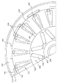
図3は本発明の磁気回路構造を適用する回転電機の一例を説明するための図である。図3に示す例には、インナーロータ201、アウターロータ211、ステータ221からなる回転電機を示している。インナーロータ201は、インナー永久磁石202、インナー電磁鋼板203及びシャフト204から構成されている。また、図中の205は、インナーロータ201とステータ221との間のステータエアーギャップを示している。アウターロータ211は、アウター永久磁石212、アウター電磁鋼板213及びアウターシェル214から構成されている。また、図中215は、アウターロータ211とステータ221との間のステータエアーギャップを示している。ステータ221は、ティース222、ステータを支えるための部材223及びステータティース222に巻回された電機子コイル224から構成されている。なお、本例では、アウター永久磁石212の両端に、ステータエアーギャップ215まで達する空気層231を設けている。また、アウター永久磁石212に対応する空気層231の間は磁性体232から構成されている。
FIG. 3 is a view for explaining an example of a rotating electrical machine to which the magnetic circuit structure of the present invention is applied. In the example illustrated in FIG. 3, a rotating electrical machine including an
本発明の磁気回路構造を適用する回転電機の特徴は、インナー永久磁石202の回転電機の中心軸に対する傾きが従来の回転電機よりも小さく、隣り合うインナー永久磁石202の間に交互に形成される外側表面の広い部分と狭い部分とのうち、広い部分が従来よりも広くなっている点と、隣り合うアウター永久磁石212の円周方向の間隔が従来の回転電機よりも大きくなっている点と、アウター永久磁石212の両端に空気層231を設けた点である。ここで、インナー永久磁石202とアウター永久磁石212の上述した構造は、後述するように、インナー磁気回路及びアウター磁気回路における磁気抵抗の低減に寄与する。また、空気層231は、アウター永久磁石212の漏れを大幅に低減でき、インナー磁束低下を招くことなく大幅なアウター磁束向上を図ることができる。
The rotating electrical machine to which the magnetic circuit structure of the present invention is applied is characterized in that the inclination of the inner
なお、回転電機の横断面を示す図3において、インナー磁気回路を、隣り合うアウター永久磁石212間の距離D1が、ステータ221を構成するステータティース222の最小幅W1と同じかそれ以上となるように配置することにより構成し、アウター磁気回路を、隣り合うインナー永久磁石202で交互に形成される外側表面の広い部分と狭い部分とのうち、広い部分の外側表面の円周方向に沿った長さL1が、アウター永久磁石間の距離D1(本例ではほぼW1と同じ)の2倍かそれ以上となるように配置することにより構成することが好ましい。
In FIG. 3 showing the cross section of the rotating electrical machine, the inner magnetic circuit is configured such that the distance D1 between the adjacent outer
図4は図3に示す回転電機における磁気回路構造の一例を説明するための図である。図4に示す例において、図3に示す部材と同一の部材には同一の符号を付し、その説明を省略する。 FIG. 4 is a diagram for explaining an example of a magnetic circuit structure in the rotating electrical machine shown in FIG. In the example shown in FIG. 4, the same members as those shown in FIG.
図4に示す例において、磁束1は、インナーロータ201に同期した磁束を示している。ここで、磁束1は、一対のN極及びS極をなすインナー永久磁石202のうちN極をなすインナー永久磁石202から出て、アウター永久磁石212の間を通過して、アウター永久磁石212の外側を通り、S極をなすインナー永久磁石202に返る磁束を示している。即ち、磁束1は、アウターロータ211を構成するアウター永久磁石212の外側が、インナー磁束の磁気回路におけるヨーク部として作用するインナー磁気回路を構成している。また、磁束1で示されるインナー磁気回路は、アウターロータ211に同期した磁束のうち横軸(q軸)磁気回路としても使用されており、アウター永久磁石212の間が大きいために横軸磁気抵抗が小さく、リラクタンストルクが発生できる機構であることがわかる。
In the example shown in FIG. 4, the
同様に、図4に示す例において、磁束2は、アウターロータ211に同期した磁束を示している。ここで、磁束2は、個々にN極とS極を有する隣接するアウター永久磁石212のうち一方のアウター永久磁石212のN極から出て、インナー永久磁石202の外側表面を通過して、他方のアウター永久磁石212のS極に返る磁束を示している。即ち、磁束2は、インナーロータ201を構成するインナー永久磁石202の外側表面が、アウター磁束の磁気回路のヨーク部として作用するアウター磁気回路を構成している。また、磁束2で示されるアウター磁気回路は、インナーロータ201に同期した磁束のうち横軸(q軸)磁気回路としても使用されており、インナー永久磁石202の外側表面が広いために横軸磁気抵抗が小さく、リラクタンストルクが発生できる機構であることがわかる。
Similarly, in the example illustrated in FIG. 4, the
上述したように、本発明の回転電機の磁気回路構造では、各ロータは横軸磁気抵抗が小さく、互いに相手側ロータのヨーク部としても作用出来るために、磁束向上、リラクタンストルクの向上が図られ、トルク密度向上に寄与する。なお、図4に示す各磁束はある瞬間のものである。 As described above, in the magnetic circuit structure of the rotating electrical machine of the present invention, each rotor has a small horizontal magnetic resistance and can also act as a yoke portion of the other rotor, so that the magnetic flux can be improved and the reluctance torque can be improved. Contributes to improved torque density. In addition, each magnetic flux shown in FIG. 4 is a thing of a certain moment.
図5は本発明の磁気回路構造を適用する回転電機の他の例を説明するための図である。図5に示す例においても、図3に示す部材と同一の部材には同一の符号を付し、その説明を省略する。図5に示す例では、ステータ221を構成するステータティース222の間であって、アウターロータ211とのエアギャップ215に露出する部分が電磁鋼板241で一体化されている。また、本例では、空気層231はエアギャップ215まで到達しておらず、磁性体232はアウター電磁鋼板213と一体化されている。これによれば、インナー磁束をアウター永久磁石212の外側へ導くことに加えて、ステータ221の外側表面でもインナー磁気回路を形成できるために、さらにインナー磁気回路のヨーク部磁気抵抗を下げることができ、インナー磁束を大幅に向上させることができる。また、アウターロータ211のような回転部でない固定されたステータ221にヨーク部を作ったために、相対回転が無く、鉄損を軽減することができる。
FIG. 5 is a diagram for explaining another example of a rotating electrical machine to which the magnetic circuit structure of the present invention is applied. Also in the example illustrated in FIG. 5, the same members as those illustrated in FIG. 3 are denoted by the same reference numerals, and the description thereof is omitted. In the example shown in FIG. 5, the portion exposed between the
図6は本発明の磁気回路構造を適用する回転電機のさらに他の例を説明するための図である。図6に示す例においても、図3に示す部材と同一の部材には同一の符号を付し、その説明を省略する。図6に示す例では、上述したアウターロータ211の空気層231と磁性体232の部分を一体の空気層251とし、アウター永久磁石212をエアギャップ215に露出させた構造を示している。これによれば、アウター永久磁石212を表面に露出させたために、アウター永久磁石212の外側のインナー磁気回路を構成するヨーク部の磁気抵抗を、図5に示した例にもまして低減することができ、インナー磁束をさらに大幅に向上させることができる。また、アウター永久磁石212を表面に出したことで、アウター永久磁石212の磁束を電磁鋼板を経ずそのままステータ221へ導くことができ、アウター永久磁石212表面の磁気抵抗を下げることが出来るため、アウター磁束の向上も合わせて可能である。
FIG. 6 is a view for explaining still another example of a rotating electrical machine to which the magnetic circuit structure of the present invention is applied. Also in the example illustrated in FIG. 6, the same members as those illustrated in FIG. 3 are denoted by the same reference numerals, and the description thereof is omitted. The example shown in FIG. 6 shows a structure in which the
図7は本発明の磁気回路構造を適用する回転電機のさらに他の例を説明するための図である。図7に示す例においても、図3に示す部材と同一の部材には同一の符号を付し、その説明を省略する。図7に示す例では、アウター永久磁石212の両端部に空気層231を設けるにあたり、一方の端部に空気層を設けた場合は他方の端部に空気層を設けず、また、他方の端部に空気層を設けた場合は一方の端部に空気層を設けないようにして、回転電機を軸方向に見たときに、空気層をアウター永久磁石の両端部に互い違いに設けた例を示している。即ち、図8に図7に示したアウターロータ211をステータ221の外周のエアーギャップ215面から見た図を示すように、空気層231を互い違いに設けている。このように互い違いに空気層231を設けることで、以下に示すようにアウター電磁鋼板213に空気層231を形成することができ、アウター電磁鋼板213と磁性体232との一体化が可能であり、大幅な機械的強度低下をきたさない。
FIG. 7 is a view for explaining still another example of a rotating electrical machine to which the magnetic circuit structure of the present invention is applied. Also in the example illustrated in FIG. 7, the same members as those illustrated in FIG. 3 are denoted by the same reference numerals, and description thereof is omitted. In the example shown in FIG. 7, when the
図9(a)〜(c)はそれぞれ空気層231の形成方法の一例を工程順に示す図である。まず、図9(a)に示すように、アウター永久磁石212を装着する部分に孔部251を有する電磁鋼板をプレス加工で作製し、作製した電磁鋼板を積み重ねることでアウター電磁鋼板213を得る。次に、図9(b)に示すように、孔部261にアウター永久磁石212を接着して固定する。その後、図9(c)に示すように、アウター永久磁石212の両端あるいは片端の必要な部分に、内周側から切削加工することで空気層231を形成する。このようにすることで、後加工で空気層231を形成できるため、アウター永久磁石212の内側の磁性体232の部分を、別体で磁性体232を設ける場合と比べて、寸法精度良くかつ強固に形成することができる。
FIGS. 9A to 9C are diagrams showing an example of a method for forming the
本発明の回転電機の磁気回路構造は、内外にロータを有し、ロータ間にステータを有する3層構造の回転電機において、ヨーク部の磁気抵抗を低減し、高トルク即ち高磁束化を磁石量を大きくせずに達成する必要のある用途に好適に用いることができる。 The magnetic circuit structure of the rotating electrical machine according to the present invention is a three-layered rotating electrical machine having a rotor inside and outside and a stator between the rotors, reducing the magnetic resistance of the yoke portion, and increasing the torque, that is, increasing the magnetic flux. It can be suitably used for applications that need to be achieved without increasing the size.
101 ステータ
102 インナーロータ
103 アウターロータ
201 インナーロータ
202 インナー永久磁石
203 インナー電磁鋼板
204 シャフト
205 エアギャップ
211 アウターロータ
212 アウター永久磁石
213 アウター電磁鋼板
214 アウターシェル
215 エアギャップ
221 ステータ
222 ステータティース
223 ステータを支える部材
224 電機子コイル
231 空気層
232 磁性体
241 電磁鋼板
251 一体の空気層
261 孔部
DESCRIPTION OF
Claims (8)
Priority Applications (4)
| Application Number | Priority Date | Filing Date | Title |
|---|---|---|---|
| JP2003352629A JP4029817B2 (en) | 2003-10-10 | 2003-10-10 | Magnetic circuit structure of rotating electrical machine |
| EP04023825A EP1528659B1 (en) | 2003-10-10 | 2004-10-06 | Magnetic circuit structure for rotary electric machine |
| US10/959,581 US7053513B2 (en) | 2003-10-10 | 2004-10-07 | Magnetic circuit structure for rotary electric machine |
| CNB2004100849378A CN100380787C (en) | 2003-10-10 | 2004-10-10 | Magnetic circuit structure for rotary electric machine |
Applications Claiming Priority (1)
| Application Number | Priority Date | Filing Date | Title |
|---|---|---|---|
| JP2003352629A JP4029817B2 (en) | 2003-10-10 | 2003-10-10 | Magnetic circuit structure of rotating electrical machine |
Publications (2)
| Publication Number | Publication Date |
|---|---|
| JP2005117870A JP2005117870A (en) | 2005-04-28 |
| JP4029817B2 true JP4029817B2 (en) | 2008-01-09 |
Family
ID=34419861
Family Applications (1)
| Application Number | Title | Priority Date | Filing Date |
|---|---|---|---|
| JP2003352629A Expired - Fee Related JP4029817B2 (en) | 2003-10-10 | 2003-10-10 | Magnetic circuit structure of rotating electrical machine |
Country Status (4)
| Country | Link |
|---|---|
| US (1) | US7053513B2 (en) |
| EP (1) | EP1528659B1 (en) |
| JP (1) | JP4029817B2 (en) |
| CN (1) | CN100380787C (en) |
Families Citing this family (22)
| Publication number | Priority date | Publication date | Assignee | Title |
|---|---|---|---|---|
| JP4239923B2 (en) * | 2004-08-02 | 2009-03-18 | 日産自動車株式会社 | Electric power transmission device |
| JP2007189890A (en) * | 2005-12-15 | 2007-07-26 | Nissan Motor Co Ltd | Rotating electric machine |
| GB2437568B (en) * | 2006-04-24 | 2009-02-11 | Univ Sheffield | Electrical machines |
| BRPI0603363B1 (en) * | 2006-08-16 | 2018-03-13 | Whirlpool S.A. | "SYNCHRONARY MACHINE" |
| KR100948103B1 (en) * | 2007-11-20 | 2010-03-17 | 박계정 | Induction motor with multi-stage rotor that can be used as a generator |
| CN101515744B (en) * | 2008-02-21 | 2011-03-23 | 高强 | Alternate current synchronous generator |
| GB0808524D0 (en) * | 2008-05-12 | 2008-06-18 | Magnomatics Ltd | Magnetic pole-piece structure |
| JP2010081784A (en) * | 2008-08-29 | 2010-04-08 | Seiko Epson Corp | Brushless electrical machine and apparatus having the same |
| US20100052444A1 (en) * | 2008-09-04 | 2010-03-04 | Young Ho Ro | Cylinder generator |
| JP5299679B2 (en) | 2009-02-06 | 2013-09-25 | 株式会社デンソー | Motor generator |
| DE102010040359A1 (en) * | 2010-09-07 | 2012-03-08 | Evelin Sommer | Electric generator and rotor blade assembly |
| DE102012222446A1 (en) * | 2012-12-06 | 2014-06-12 | Robert Bosch Gmbh | Wheel hub machine, single track vehicle |
| EP2940841B1 (en) * | 2012-12-28 | 2018-04-11 | IHI Corporation | Double stator switched reluctance rotating machine |
| WO2014109218A1 (en) | 2013-01-10 | 2014-07-17 | 株式会社Ihi | Double stator switched reluctance rotating machine |
| WO2015039610A1 (en) * | 2013-09-22 | 2015-03-26 | 格源动力有限公司 | Coaxial motor having one gear shift |
| US9130433B2 (en) | 2013-11-14 | 2015-09-08 | Arm Limited | Electronically controlled universal motor |
| CN109417320B (en) * | 2016-07-11 | 2020-08-21 | 三菱电机株式会社 | Rotor, motor, blower, compressor, and air conditioner |
| JP2020014342A (en) * | 2018-07-19 | 2020-01-23 | シナノケンシ株式会社 | Magnetic reduction gear |
| JP2020096484A (en) * | 2018-12-14 | 2020-06-18 | Tdk株式会社 | Permanent magnet and rotating electric machine |
| JP7331356B2 (en) * | 2018-12-14 | 2023-08-23 | Tdk株式会社 | Permanent magnets and rotating electrical machines |
| WO2020242222A1 (en) * | 2019-05-28 | 2020-12-03 | 엘지이노텍 주식회사 | Motor |
| EP3993223A4 (en) * | 2019-06-26 | 2022-08-31 | Sony Group Corporation | Motor, and motor control device |
Family Cites Families (16)
| Publication number | Priority date | Publication date | Assignee | Title |
|---|---|---|---|---|
| US5808392A (en) * | 1994-04-28 | 1998-09-15 | Kabushiki Kaisha Toshiba | Permanent magnet type rotating machine |
| CN2250596Y (en) * | 1995-12-15 | 1997-03-26 | 中国科学院电工研究所 | High speed motor for flywheel battery |
| US5811904A (en) * | 1996-03-21 | 1998-09-22 | Hitachi, Ltd. | Permanent magnet dynamo electric machine |
| JP3308828B2 (en) * | 1996-10-18 | 2002-07-29 | 株式会社日立製作所 | Permanent magnet rotating electric machine and electric vehicle using the same |
| US6008559A (en) * | 1997-07-22 | 1999-12-28 | Matsushita Electric Industrial Co., Ltd. | Motor using a rotor including an interior permanent magnet |
| JP3627559B2 (en) | 1999-01-29 | 2005-03-09 | 日産自動車株式会社 | Multilayer motor |
| JP3663997B2 (en) | 1999-09-27 | 2005-06-22 | 日産自動車株式会社 | Multiple rotor motor |
| DE60027840T2 (en) * | 1999-11-18 | 2006-12-28 | Denso Corp., Kariya | Rotary electric machine for vehicles |
| JP3403690B2 (en) * | 2000-03-02 | 2003-05-06 | 株式会社日立製作所 | Hybrid electric vehicle using permanent magnet type rotating electric machine |
| JP3787756B2 (en) * | 2000-08-29 | 2006-06-21 | 株式会社日立製作所 | Permanent magnet rotating electric machine |
| JP4662220B2 (en) * | 2001-05-31 | 2011-03-30 | 本田技研工業株式会社 | Electric assist bicycle |
| JP3543792B2 (en) * | 2001-07-18 | 2004-07-21 | 日産自動車株式会社 | Rotating electric machine |
| CN1258254C (en) * | 2002-04-01 | 2006-05-31 | 日产自动车株式会社 | Stator cooling structure for multi-axis and multi-layer motors |
| JP3716809B2 (en) * | 2002-04-01 | 2005-11-16 | 日産自動車株式会社 | Rotating electric machine |
| WO2003084029A1 (en) * | 2002-04-01 | 2003-10-09 | Nissan Motor Co., Ltd. | Cooling structure for multi-shaft, multi-layer electric motor |
| JP3903956B2 (en) * | 2003-05-23 | 2007-04-11 | 日産自動車株式会社 | Multi-axis multilayer motor |
-
2003
- 2003-10-10 JP JP2003352629A patent/JP4029817B2/en not_active Expired - Fee Related
-
2004
- 2004-10-06 EP EP04023825A patent/EP1528659B1/en not_active Expired - Lifetime
- 2004-10-07 US US10/959,581 patent/US7053513B2/en not_active Expired - Lifetime
- 2004-10-10 CN CNB2004100849378A patent/CN100380787C/en not_active Expired - Fee Related
Also Published As
| Publication number | Publication date |
|---|---|
| EP1528659B1 (en) | 2012-11-21 |
| US20050077802A1 (en) | 2005-04-14 |
| CN100380787C (en) | 2008-04-09 |
| CN1606217A (en) | 2005-04-13 |
| US7053513B2 (en) | 2006-05-30 |
| JP2005117870A (en) | 2005-04-28 |
| EP1528659A3 (en) | 2005-10-12 |
| EP1528659A2 (en) | 2005-05-04 |
Similar Documents
| Publication | Publication Date | Title |
|---|---|---|
| JP4029817B2 (en) | Magnetic circuit structure of rotating electrical machine | |
| JP4220324B2 (en) | Rotating electric machine | |
| JP3903956B2 (en) | Multi-axis multilayer motor | |
| JP2004312845A (en) | Stator for motor | |
| JP4069859B2 (en) | Structure of rotating electrical machine | |
| JP3550971B2 (en) | Electric motor | |
| JP4111117B2 (en) | Rotation machine rotation sensor arrangement structure | |
| JP2010206861A (en) | Rotating electrical machine | |
| JP4127228B2 (en) | Stator structure of rotating electrical machine | |
| JP2005124356A (en) | Magnetic circuit structure of rotating electrical machine | |
| JP4016931B2 (en) | Multi-axis multilayer motor | |
| JP2006014560A (en) | Stator core structure of rotating electrical machine | |
| JP2005117740A (en) | Laminated core structure of rotating electrical machine and method of manufacturing | |
| JP2005168205A (en) | Stator core structure of rotating electrical machine | |
| JP2005295740A (en) | Stator structure of rotating electrical machine | |
| JP2005057906A (en) | Multi-axis multilayer motor structure | |
| JP4135627B2 (en) | Stator structure of rotating electrical machine | |
| JP4111124B2 (en) | Stator structure of rotating electrical machine | |
| JP2004312800A (en) | Stator structure of multi-axis multilayer motor | |
| JP2006166624A (en) | Stator core structure of rotating electrical machines | |
| JP4093195B2 (en) | Stator structure of rotating electrical machine | |
| JP4114621B2 (en) | Structure of rotating electrical machine | |
| JP4135611B2 (en) | Stator structure of rotating electrical machine | |
| JP2005124301A (en) | Rotor structure of rotating electrical machine | |
| JP2006081344A (en) | Combined rotary electric machine |
Legal Events
| Date | Code | Title | Description |
|---|---|---|---|
| A621 | Written request for application examination |
Free format text: JAPANESE INTERMEDIATE CODE: A621 Effective date: 20060529 |
|
| TRDD | Decision of grant or rejection written | ||
| A01 | Written decision to grant a patent or to grant a registration (utility model) |
Free format text: JAPANESE INTERMEDIATE CODE: A01 Effective date: 20070925 |
|
| A61 | First payment of annual fees (during grant procedure) |
Free format text: JAPANESE INTERMEDIATE CODE: A61 Effective date: 20071008 |
|
| R150 | Certificate of patent or registration of utility model |
Ref document number: 4029817 Country of ref document: JP Free format text: JAPANESE INTERMEDIATE CODE: R150 Free format text: JAPANESE INTERMEDIATE CODE: R150 |
|
| FPAY | Renewal fee payment (event date is renewal date of database) |
Free format text: PAYMENT UNTIL: 20101026 Year of fee payment: 3 |
|
| FPAY | Renewal fee payment (event date is renewal date of database) |
Free format text: PAYMENT UNTIL: 20111026 Year of fee payment: 4 |
|
| FPAY | Renewal fee payment (event date is renewal date of database) |
Free format text: PAYMENT UNTIL: 20121026 Year of fee payment: 5 |
|
| FPAY | Renewal fee payment (event date is renewal date of database) |
Free format text: PAYMENT UNTIL: 20121026 Year of fee payment: 5 |
|
| FPAY | Renewal fee payment (event date is renewal date of database) |
Free format text: PAYMENT UNTIL: 20131026 Year of fee payment: 6 |
|
| LAPS | Cancellation because of no payment of annual fees |