JP2025100763A - Information processing device, information processing method, and program - Google Patents
Information processing device, information processing method, and program Download PDFInfo
- Publication number
- JP2025100763A JP2025100763A JP2025068136A JP2025068136A JP2025100763A JP 2025100763 A JP2025100763 A JP 2025100763A JP 2025068136 A JP2025068136 A JP 2025068136A JP 2025068136 A JP2025068136 A JP 2025068136A JP 2025100763 A JP2025100763 A JP 2025100763A
- Authority
- JP
- Japan
- Prior art keywords
- image
- model
- information
- virtual viewpoint
- viewpoint image
- Prior art date
- Legal status (The legal status is an assumption and is not a legal conclusion. Google has not performed a legal analysis and makes no representation as to the accuracy of the status listed.)
- Pending
Links
Images


Classifications
-
- A—HUMAN NECESSITIES
- A63—SPORTS; GAMES; AMUSEMENTS
- A63F—CARD, BOARD, OR ROULETTE GAMES; INDOOR GAMES USING SMALL MOVING PLAYING BODIES; VIDEO GAMES; GAMES NOT OTHERWISE PROVIDED FOR
- A63F13/00—Video games, i.e. games using an electronically generated display having two or more dimensions
- A63F13/50—Controlling the output signals based on the game progress
- A63F13/52—Controlling the output signals based on the game progress involving aspects of the displayed game scene
- A63F13/525—Changing parameters of virtual cameras
- A63F13/5255—Changing parameters of virtual cameras according to dedicated instructions from a player, e.g. using a secondary joystick to rotate the camera around a player's character
-
- G—PHYSICS
- G06—COMPUTING OR CALCULATING; COUNTING
- G06T—IMAGE DATA PROCESSING OR GENERATION, IN GENERAL
- G06T15/00—Three-dimensional [3D] image rendering
- G06T15/10—Geometric effects
- G06T15/20—Perspective computation
-
- B—PERFORMING OPERATIONS; TRANSPORTING
- B33—ADDITIVE MANUFACTURING TECHNOLOGY
- B33Y—ADDITIVE MANUFACTURING, i.e. MANUFACTURING OF THREE-DIMENSIONAL [3D] OBJECTS BY ADDITIVE DEPOSITION, ADDITIVE AGGLOMERATION OR ADDITIVE LAYERING, e.g. BY 3D PRINTING, STEREOLITHOGRAPHY OR SELECTIVE LASER SINTERING
- B33Y50/00—Data acquisition or data processing for additive manufacturing
-
- G—PHYSICS
- G06—COMPUTING OR CALCULATING; COUNTING
- G06T—IMAGE DATA PROCESSING OR GENERATION, IN GENERAL
- G06T7/00—Image analysis
- G06T7/50—Depth or shape recovery
-
- G—PHYSICS
- G06—COMPUTING OR CALCULATING; COUNTING
- G06T—IMAGE DATA PROCESSING OR GENERATION, IN GENERAL
- G06T7/00—Image analysis
- G06T7/70—Determining position or orientation of objects or cameras
-
- H—ELECTRICITY
- H04—ELECTRIC COMMUNICATION TECHNIQUE
- H04N—PICTORIAL COMMUNICATION, e.g. TELEVISION
- H04N23/00—Cameras or camera modules comprising electronic image sensors; Control thereof
- H04N23/60—Control of cameras or camera modules
-
- H—ELECTRICITY
- H04—ELECTRIC COMMUNICATION TECHNIQUE
- H04N—PICTORIAL COMMUNICATION, e.g. TELEVISION
- H04N23/00—Cameras or camera modules comprising electronic image sensors; Control thereof
- H04N23/90—Arrangement of cameras or camera modules, e.g. multiple cameras in TV studios or sports stadiums
Landscapes
- Engineering & Computer Science (AREA)
- Theoretical Computer Science (AREA)
- Physics & Mathematics (AREA)
- General Physics & Mathematics (AREA)
- Multimedia (AREA)
- Computer Vision & Pattern Recognition (AREA)
- Signal Processing (AREA)
- Computer Graphics (AREA)
- Geometry (AREA)
- Computing Systems (AREA)
- Chemical & Material Sciences (AREA)
- Manufacturing & Machinery (AREA)
- Materials Engineering (AREA)
- Processing Or Creating Images (AREA)
- Image Generation (AREA)
- Closed-Circuit Television Systems (AREA)
- Studio Devices (AREA)
Abstract
【課題】造形物に対応する所定のシーンの仮想視点画像を生成する。【解決手段】仮想視点画像のシーンにおける特定の時刻に対応したシーンに基づいて生成された生成物を撮像して撮像画像を取得する。生成物の撮像画像を用いて、特定の時刻に対応したシーンの仮想視点画像を生成する。【選択図】図6A virtual viewpoint image of a predetermined scene corresponding to a shaped object is generated. A captured image is obtained by capturing an image of a product generated based on a scene corresponding to a specific time in the scene of the virtual viewpoint image. A virtual viewpoint image of the scene corresponding to the specific time is generated using the captured image of the product. [Selected Figure] FIG.
Description
本開示は、情報処理装置、情報処理方法、およびプログラムに関する。 The present disclosure relates to an information processing device, an information processing method, and a program.
2次元マーカをスマートフォン等の携帯端末で撮像して得た撮像画像を基に携帯端末の位置およびその姿勢等を算出し、算出した位置および姿勢に応じた仮想視点画像を生成する技術がある。この技術は様々な分野で利用されており、例えば、拡張現実(AR:Augumented Reality)に関する技術で利用されている。特許文献1は、2次元マーカを撮像時に手ぶれなどにより生じる、仮想視点画像の傾きを補正する技術を開示している。 There is a technology that calculates the position and orientation of a mobile device such as a smartphone based on the captured image of a two-dimensional marker, and generates a virtual viewpoint image according to the calculated position and orientation. This technology is used in a variety of fields, for example, in technology related to augmented reality (AR). Patent Document 1 discloses a technology that corrects the tilt of a virtual viewpoint image caused by camera shake when capturing an image of a two-dimensional marker.
一方、近年、3Dプリンタ等を用いて、実在の人物などを撮像又はスキャンして得たオブジェクトの3Dモデル(三次元形状を表す形状データ)を基に人物などのフィギュアを生成することも行われている。 On the other hand, in recent years, 3D printers and other devices have been used to generate figures of people and other objects based on 3D models (shape data representing three-dimensional shapes) of objects obtained by photographing or scanning real people and other objects.
人物などのフィギュアを、仮想視点画像のあるシーンに基づいて生成することも可能であるところ、生成されたフィギュアが対応するシーンが元の仮想視点画像のどのシーンであるか等、当該生成されたフィギュアに関する知見を深めたという要望がある。また、仮想視点画像のあるシーンから別の仮想視点に対応する新たな仮想視点画像を生成することもあるが、この場合も、同様に、当該生成された仮想視点画像に関する知見を深めたいという要望がある。 It is possible to generate figures such as people based on a scene in a virtual viewpoint image, but there is a demand for deeper knowledge about the generated figures, such as which scene in the original virtual viewpoint image the generated figure corresponds to. Also, a new virtual viewpoint image corresponding to a different virtual viewpoint may be generated from a scene in a virtual viewpoint image, and in this case, there is a demand for deeper knowledge about the generated virtual viewpoint image.
本開示の一態様に係る情報処理装置は、仮想視点画像における特定の時刻に対応したシーンに基づいて生成された生成物を撮像して撮像画像を取得する取得手段と、前記生成物の撮像画像を用いて、前記特定の時刻に対応したシーンの仮想視点画像を生成する生成手段と、を有することを特徴とする。 An information processing device according to one aspect of the present disclosure is characterized by having an acquisition means for capturing an image of a product generated based on a scene corresponding to a specific time in a virtual viewpoint image, and a generation means for generating a virtual viewpoint image of the scene corresponding to the specific time using the captured image of the product.
本開示によれば、造形物に対応する所定のシーンの仮想視点画像を生成することができる。 According to the present disclosure, it is possible to generate a virtual viewpoint image of a specified scene corresponding to a model.
以下、本発明の実施形態について、図面を参照して説明する。なお、以下の実施形態は、特許請求の範囲に係る本開示を限定するものではなく、また本実施形態で説明されている特徴の組み合わせの全てが本開示の解決手段に必須のものとは限らない。なお、同一の構成要素には同一の参照番号を付して、その説明を省略する。 Below, an embodiment of the present invention will be described with reference to the drawings. Note that the following embodiment does not limit the present disclosure related to the claims, and not all of the combinations of features described in the present embodiment are necessarily essential to the solution of the present disclosure. Note that the same components are given the same reference numbers and their description will be omitted.
[実施形態1]
本実施形態では、仮想視点画像の生成で用いた3Dモデルと同じ3Dモデルを基に生成された生成物の撮像画像から、生成物の生成で用いたDモデルと同じ3Dモデルに対応する仮想視点画像を生成する又はそれに関する情報を取得する態様について説明する。なお、仮想視点画像とは、エンドユーザおよび/または選任のオペレータなどが仮想視点に対応するカメラ(仮想カメラ)の位置および姿勢(向き)を操作することによって生成される画像であり、自由視点画像や任意視点画像などとも呼ばれる。仮想視点画像は、動画であっても、静止画であってもよいが、本実施形態では動画の場合を例に説明する。3Dモデルは、オブジェクトの三次元形状を表す形状データである。
[Embodiment 1]
In this embodiment, a virtual viewpoint image corresponding to the same 3D model as the D model used in generating the product is generated from a captured image of the product generated based on the same 3D model as the 3D model used in generating the virtual viewpoint image, or information about the same is acquired. Note that the virtual viewpoint image is an image generated by an end user and/or a designated operator manipulating the position and attitude (direction) of a camera (virtual camera) corresponding to a virtual viewpoint, and is also called a free viewpoint image or an arbitrary viewpoint image. The virtual viewpoint image may be a video or a still image, but in this embodiment, a video is used as an example. The 3D model is shape data that represents the three-dimensional shape of an object.
(システムの構成)
図1は、第一出力物(生成物)の撮像画像を基に、第一出力物の3Dモデルに対応する仮想視点画像またはそれに関する情報を第二出力物として生成する情報処理システム(仮想視点画像生成システム)の構成例を示す図である。図1(a)に情報処理システム100の構成例を示し、図1(b)に情報処理システムが有するセンサシステムの設置例を示す。情報処理システム(仮想視点画像生成システム)100は、データベース103と、画像生成装置104と、携帯端末105と、造形装置106とを有する。
(System Configuration)
Fig. 1 is a diagram showing a configuration example of an information processing system (virtual viewpoint image generation system) that generates a virtual viewpoint image corresponding to a 3D model of a first output object (product) or information related thereto as a second output object based on a captured image of the first output object (product). Fig. 1(a) shows a configuration example of the
データベース103は、イベント情報および3Dモデル情報などを管理する。イベント情報は、撮像対象のイベントの全タイムコードに対応付けられた、オブジェクト毎の3Dモデル情報の格納先を示すデータを含む。オブジェクトは、ユーザが造形したい人およびものを含んでもよいし、造形対象でない人および物を含んでもよい。3Dモデル情報は、オブジェクトの3Dモデルに関する情報を含む。
The
これら情報は、例えば、情報処理システム100が有するセンサシステムで取得した情報でもよいし、情報処理システム100と異なる別のシステムが有するセンサシステムで取得した情報でもよい。センサシステムは、例えば、図1(b)に示すように、それぞれは少なくとも1台の撮像装置であるカメラを有するセンサシステム101a-101nを有する。なお、以下では、特に説明がない限り、センサシステム101aからセンサシステム101nまでのn台のセンサシステムを区別せず、複数センサシステム101と表記する。複数センサシステム101は、撮像の対象領域である領域120を囲むように設置され、複数センサシステム101のカメラは、それぞれ異なる方向から領域120を撮像する。仮想カメラ110は、複数センサシステム101のカメラと異なる方向から、領域120を撮像する。仮想カメラ110の詳細については後述する。
These pieces of information may be, for example, information acquired by a sensor system included in the
撮像対象が、ラグビーやサッカー等のプロスポーツの試合である場合、領域120はスタジアムのフィールドとなり、n台(例えば100台)の複数センサシステム101は、フィールドを囲むように設置される。また、撮像対象の領域120にはフィールド上の人だけでなくボールやその他の物体があってもよい。なお、撮像対象はスタジアムのフィールドに限定されず、アリーナ等で行われる音楽ライブや、スタジオで行われるCM撮影であってもよく、複数センサシステム101が設置できればよい。なお、設置されるセンサシステム101の台数は限定されない。また、複数センサシステム101は領域120の全周に渡って設置されていなくてもよく、設置場所の制限等によっては領域120の周囲の一部にのみ設置されてもよい。また、複数センサシステム101が有する複数のカメラには、望遠カメラと広角カメラなど機能が異なる撮像装置が含まれていてもよい。
When the subject of imaging is a professional sports match such as rugby or soccer, the
複数センサシステム101が有する複数のカメラは同期して撮像を行い、複数の画像を取得する。なお、複数の画像のそれぞれは、撮像画像であってもよいし、撮像画像に対して例えば所定の領域を抽出する処理などの画像処理を行うことで得られた画像であってもよい。 The multiple cameras in the multi-sensor system 101 capture images synchronously to obtain multiple images. Each of the multiple images may be a captured image, or may be an image obtained by performing image processing on the captured image, such as a process of extracting a specific area.
なお、センサシステム101a-101nそれぞれは、カメラに加えてマイク(不図示)を有してもよい。複数センサシステム101それぞれのマイクは同期して音声を収音する。この収音された音声に基づき、画像生成装置104における画像の表示と共に再生される音響信号を生成することができる。以降、説明の簡略化のため、音声についての記載を省略するが、基本的に画像と音声は共に処理されるものとする。
Note that each of the
複数センサシステム101が取得した複数の画像と、撮像に使用したタイムコードとは、合わされてデータベース103に記憶される。タイムコードとは、撮像した時刻を一意に識別するための絶対値で表される時間情報あって、例えば、日:時:分:秒.フレーム番号の様な形式で指定可能な時間情報である。
The multiple images acquired by the multiple sensor system 101 and the time code used for capturing the images are combined and stored in the
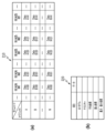
データベース103が管理するイベント情報および3Dモデル情報のテーブル例について図を用いて説明する。図2は、データベース103が管理する情報のテーブル例を示す図であり、図2(a)にイベント情報のテーブルを示し、図2(b)に3Dモデル情報のテーブルを示す。データベース103が管理するイベント情報のテーブル210は、図2(a)に示すように、撮像対象のイベントの全てのタイムコードについて、オブジェクト毎の3Dモデル情報の格納先を示している。イベント情報のテーブル210では、例えば、タイムコードが「16:14:24.041」であり、オブジェクトがオブジェクトAである3Dモデル情報の格納先が、「DataA100」であることを示している。なお、イベント情報のテーブル210は、全てのタイムコードに限定されず、一部のタイムコードについて3Dモデル情報の格納先を示していてもよい。タイムコードは撮像した時刻を一意に識別するための絶対値であって、例えば、「日:時:分:秒.フレーム番号」の様な形式で指定可能である。
An example of a table of event information and 3D model information managed by the
データベース103が管理する3Dモデル情報のテーブル220は、図2(b)に示すように、「3Dモデル」、「テクスチャ」、「平均座標」、「重心座標」、「最大・最小座標」の各項目についてのデータが格納されている。「3Dモデル」には、例えば、点群やメッシュ等の3Dモデルそのものに関するデータが格納されている。「テクスチャ」には、3Dモデルに付与するテクスチャ画像に関するデータが格納されている。「平均座標」には、3Dモデルを構成する点群の座標の全てを平均した点の座標に関するデータが格納されている。「重心座標」には、3Dモデルを構成する点群の座標の全てを基に重心となる点の座標に関するデータが格納されている。「最大・最小座標」には、3Dモデルを構成する点群の座標のうち最大・最小となる点の座標に関するデータが格納されている。なお、3Dモデル情報のテーブル220に格納されるデータの項目は、「3Dモデル」、「テクスチャ」、「平均座標」、「重心座標」、「最大・最小座標」の全てに限らない。例えば、「3Dモデル」および「テクスチャ」だけでもよいし、この項目に他の項目を加えてもよい。また、データベース103は、3Dモデルに関する情報(不図示)を管理する。3Dモデルに関する情報は、撮像対象がラグビーの試合であれば、ラグビーの試合の開催日および開催場所や対戦カードに関する情報、ラグビー選手に関する情報などを含む。
As shown in FIG. 2B, the 3D model information table 220 managed by the
図2に示す情報を使用することで、あるタイムコードが指定されると、指定されたタイムコードにおける3Dモデル情報として、オブジェクト毎の3Dモデルやテクスチャ画像を取得することができる。例えば、図2(a)では、タイムコード「16:14:24.041」におけるオブジェクトNの3Dモデル情報としてDataN100を取得できる。その他のタイムコードやオブジェクトに対する3Dモデル情報も同様に指定することで取得可能である。また、あるタイムコードを指定し、そのタイムコードにおける全オブジェクトの3Dモデル情報をまとめて取得してもよい。例えば、タイムコード「16:14:25.021」を指定し、全オブジェクトの3Dモデル情報DataA141、DataB141、・・・、DataN141を取得してもよい。 By using the information shown in FIG. 2, when a certain time code is specified, a 3D model and texture image for each object can be obtained as 3D model information at the specified time code. For example, in FIG. 2(a), DataN100 can be obtained as 3D model information for object N at time code "16:14:24.041". 3D model information for other time codes and objects can also be obtained by specifying them in the same way. Also, a certain time code may be specified and 3D model information for all objects at that time code may be obtained all at once. For example, time code "16:14:25.021" may be specified and 3D model information DataA141, DataB141, ..., DataN141 for all objects may be obtained.
上述の様に複数センサシステムの撮像で得た画像を多視点画像と呼び、この様な多視点画像からオブジェクトの三次元形状を表す3Dモデルを生成することができる。具体的には、多視点画像から、人物やボール等のオブジェクトに対応する前景領域を抽出した前景画像と、前景領域以外の背景領域を抽出した背景画像が取得され、複数の前景画像に基づいて前景の3Dモデルをオブジェクト毎に生成することができる。これらの3Dモデルは、例えばVisual Hull等の形状推定方法により生成され、点群で構成される。ただし、オブジェクト毎の形状を表す3Dモデルのデータ形式はこれに限定されない。そして、この様に生成された3Dモデルは、タイムコード毎およびオブジェクト毎にデータベース103へ記録される。なお、3Dモデルの生成方法はこれに限定されず、データベース103に3Dモデルが記録されていればよい。
As described above, images obtained by imaging with a multiple sensor system are called multi-view images, and a 3D model representing the three-dimensional shape of an object can be generated from such a multi-view image. Specifically, a foreground image in which a foreground region corresponding to an object such as a person or a ball is extracted, and a background image in which a background region other than the foreground region is extracted are obtained from the multi-view image, and a foreground 3D model can be generated for each object based on the multiple foreground images. These 3D models are generated by a shape estimation method such as Visual Hull, and are composed of point clouds. However, the data format of the 3D model representing the shape of each object is not limited to this. The 3D models generated in this manner are recorded in the
なお、フィールドや観客席などの背景のオブジェクトの3Dモデルに関して、タイムコード00:00:00.000等に3Dモデル情報としてデータベース103へ記録してもよい。
Note that 3D models of background objects such as the field and spectator seats may be recorded in
図1(a)の説明に戻る。画像生成装置104は、データベース103から3Dモデルを取得し、取得した3Dモデルを基に仮想視点画像を生成する。具体的には、画像生成装置104は、取得した3Dモデルを構成する点毎に、多視点画像から適切な画素値を取得して色付け処理を行う。そして色付けされた3Dモデルを三次元の仮想空間に配置して、仮想カメラへ投影してレンダリングすることで、仮想視点画像を生成する。また、画像生成装置104は、仮想視点画像に関する情報を生成する。
Returning to the explanation of FIG. 1(a), the
仮想カメラ110は、例えば、図1(b)に示すように、対象となる領域120に関連付けられた仮想空間内に設定され、複数センサシステム101のどのカメラとも異なる視点から領域120を閲覧できる。仮想カメラ110の視点は、その位置および姿勢によって決定される。仮想カメラ110の位置および姿勢の詳細については後述する。
The
画像生成装置104は、仮想カメラの位置および姿勢を、携帯端末105から送られる情報によって決定してもよい。この処理の詳細に関しては図を用いて後述する。
The
仮想視点画像は、仮想カメラ110からの見えを表す画像であり、自由視点映像とも呼ばれる。画像生成装置104で生成された仮想視点画像やそれに関する情報は、画像生成装置104に表示してもよいし、撮像データの送信元である別デバイスの携帯端末105へ応答として返信されて携帯端末105に表示してもよい。当然、仮想視点画像は画像生成装置104および携帯端末105の両方に表示してもよい。
The virtual viewpoint image is an image that represents the view from the
造形装置106は、例えば、3Dプリンタなどであり、画像生成装置104によって生成された仮想視点画像を基に、例えば人形(3Dモデルフィギュア)などの第一出力物107を造形する。第一出力物107は、データベース103に記録された3Dモデルに基づき生成される出力物であって、本実施形態では、携帯端末105によって撮像される対象物である。第一出力物の例として、3Dプリンタ等の造形装置106によって、3Dモデルを用いて造形された3Dモデルフィギュア等が挙げられる。ここで、第一出力物107例である3Dモデルフィギュアについて図を用いて説明する。
The
図3は、3Dモデルフィギュアを撮像し、この撮像画像を基に3Dモデルフィギュアの関連情報を生成する処理を説明する図である。図3(a)に3Dモデルフィギュア例を示し、図3(b)に図3(a)の3Dモデルフィギュアの撮像画像例を示し、図3(c)に図3(a)の3Dモデルフィギュアに対応する仮想視点画像例を示す。図3(a)では、データベース103にラグビーの試合を対象とした3Dモデルが記録されていて、あるタイムコードにおける3Dモデルを用いた造形例を示している。具体的には、ラグビーの試合中に得点に繋がる様な決定的シーンとしてオフロードパスが行われた場面が選ばれ、そのタイムコードに対応付けられた3Dモデルを用いて造形された例を示している。
Figure 3 is a diagram explaining the process of capturing an image of a 3D model figure and generating related information for the 3D model figure based on the captured image. Figure 3(a) shows an example of a 3D model figure, Figure 3(b) shows an example of a captured image of the 3D model figure in Figure 3(a), and Figure 3(c) shows an example of a virtual viewpoint image corresponding to the 3D model figure in Figure 3(a). In Figure 3(a), 3D models of rugby matches are recorded in the
図3(a)に示すように、3Dモデルフィギュアは、台座301と、第1フィギュア体302と、第2フィギュア体303と、第3フィギュア体304とを有する。第1フィギュア体302、第2フィギュア体303および第3フィギュア体304は、それぞれオブジェクトである各選手に対応しており、台座301の上に固定されている。図3(a)では、第3フィギュア体304の選手がボールを持って、オフロードパスをする瞬間の3Dモデルフィギュアとなっている。
As shown in FIG. 3(a), the 3D model figure has a
また、台座301の前面および側面には、携帯端末105で撮像時の撮像方向および姿勢等の情報を保持する2次元コード311、312が付与されている。図3(a)に示される第一出力物の台座301には2つの2次元コード311、312が付与されるが、第一出力物に付与される2次元コードの数および位置はこれに限定されない。また、2次元コードに含まれる情報は撮像方向および姿勢だけでなく、3Dモデルが撮像された試合情報などの、第一出力物に関連する画像情報を含めてもよい。なお、第一の出力物に情報を付与する形態は2次元コードに限定されず、透かし情報などの他の形態でもよい。
In addition, two-
第一出力物107は、3Dモデルフィギュアのような立体物に限定されず、データベース103にある3Dモデルを使用し生成されたものであればよい。例えば、プレートなどに印字される造形物でもよいし、ディスプレイに表示される仮想視点画像でもよい。
The
画像生成装置104が、データベース103にある3Dモデルを取得してから、造形装置106へ出力し、3Dモデルフィギュアなどの第一出力物107を造形してもよい。
The
図1の説明に戻る。携帯端末105は、3Dモデルフィギュアなどの第一出力物107を撮像し、その撮像データを画像生成装置104へ送信する。撮像データ(撮像画像)は、画像データでもよいし、画像データに属性情報を含めたデータでもよい。ここで、撮像画像例について、図3(b)を用いて説明する。図3(b)では、第一出力物として図3(a)に示した3Dモデルフィギュアを撮像して得た画像が携帯端末の表示部に表示された状態を示している。携帯端末105は、第一出力物の撮像データを画像生成装置に送信し、その応答として、画像生成装置104が生成した仮想視点画像や、それに関する画像情報を第二出力物として受け取って表示する。これらの処理の詳細については図を用いて後述する。
Returning to the explanation of FIG. 1, the
なお、本実施形態では仮想視点画像が動画の場合を中心に説明するが、静止画でもよい。 Note that in this embodiment, the virtual viewpoint image will be described mainly as a video, but it may also be a still image.
(画像生成装置の構成)
画像生成装置104の構成例について図を用いて説明する。図4は、画像生成装置104の構成例を示す図であり、図4(a)に画像生成装置104の機能構成例を示し、図4(b)に画像生成装置104のハードウェア構成例を示す。
(Configuration of the image generating device)
An example of the configuration of the
画像生成装置104は、図4(a)に示すように、撮像データ処理部401と、仮想カメラ制御部402と、3Dモデル取得部403と、画像生成部404と、出力データ制御部405とを有する。画像生成装置104は、前述の機能部を使用し、3Dモデルから生成された第一出力物を撮像して得た撮像データを用いて、同3Dモデルから生成される仮想視点画像や、それに関する画像情報を第二出力物として生成する。ここでは、各機能の概要を説明し、各処理の詳細については後述する。
As shown in FIG. 4(a), the
撮像データ処理部401は、携帯端末105が第一出力物を撮像して得た撮像データを受け取る。そして、撮像データ処理部401は、受け取った撮像データから、第一出力物の生成情報を取得する。第一出力物の生成情報とは、第一出力物を生成するためのデータを識別するための情報である。例えば、第一出力物の元になった3Dモデルが記録されたデータベースの識別子、その3Dモデルのタイムコードなどである。データベースの識別子は、対応するデータベースを一意に識別するための情報である。よって、これらの情報によって第一出力物の元になった3Dモデルを一意に識別することができる。
The imaging
また、撮像データ処理部401は、撮像データより、第一出力物を撮像した撮像装置の位置およびその姿勢や、焦点距離等の情報(以降、撮像情報と呼ぶ)を取得する。撮像装置の位置およびその姿勢は、撮像データに含まれる2次元コード311、312等から取得してもよいし、その他の方法で取得してもよい。その他の取得方法例については実施形態2に示す。
The imaging
なお、撮像データより取得できる第一出力物の生成情報や、撮像情報は、これらに限定されない。例えば、第一出力物がスポーツの試合に関するものであれば、試合結果や対戦チーム情報の関連情報等が含まれてもよい。 Note that the generation information and imaging information of the first output product that can be obtained from the imaging data are not limited to these. For example, if the first output product is related to a sports match, related information such as the match results and information on the opposing teams may be included.
仮想カメラ制御部402は、撮像データ処理部401を介して取得した撮像装置の位置およびその姿勢や焦点距離に応じて仮想カメラを制御する。仮想カメラや、その位置およびその姿勢の詳細については、図を用いて後述する。
The virtual
3Dモデル取得部403は、撮像データ処理部401を介して取得したデータベースの識別子やタイムコードを指定し、データベース103から該当する3Dモデルを取得する。なお、タイムコードは、携帯端末105に対するユーザ操作などにより指定されてもよい。
The 3D
画像生成部404は、3Dモデル取得部403が取得した3Dモデルを基に仮想視点画像を生成する。具体的には、画像生成部404は、3Dモデルを構成する点毎に、画像から適切な画素値を取得して色付け処理を行う。そして、画像生成部404は、色付けされた3Dモデルを三次元の仮想空間に配置し、仮想カメラ制御部402が制御した仮想カメラ(仮想視点)へ投影してレンダリングすることで、仮想視点画像を生成する。
The
ここで生成される仮想視点画像は、撮像データ処理部401が第一出力物の撮像データより取得した第一出力物の生成情報(3Dモデルを識別する情報)と、撮像情報(第一出力物を撮像した撮像装置位置およびその姿勢等)を用いて、生成されたものとなる。
The virtual viewpoint image generated here is generated using the generation information of the first output object (information that identifies the 3D model) acquired by the imaging
なお、仮想視点画像の生成方法は、これに限定されず、3Dモデルを用いずに撮像画像の射影変換により仮想視点画像を生成する方法など、種々の方法を使用してもよい。 Note that the method for generating the virtual viewpoint image is not limited to this, and various methods may be used, such as a method for generating a virtual viewpoint image by projective transformation of a captured image without using a 3D model.
出力データ制御部405は、画像生成部404が生成した仮想視点画像を第二出力物として外部装置、例えば、携帯端末105へ出力する。また、撮像データ処理部401が取得した第一出力物に関する関連情報を、第二出力物として外部装置へ出力してもよい。
The output
なお、出力データ制御部405は、3Dモデルから造形用データを生成し、生成した造形用データを造形装置106に出力して、造形装置106にて第一出力物を得てもよい。
In addition, the output
(画像生成装置のハードウェア構成)
次に、画像生成装置104のハードウェア構成について、図4(b)を用いて説明する。画像生成装置104は、図4(b)に示すように、CPU411と、RAM412と、ROM413と、操作入力部414と、表示部415と、通信I/F(インターフェイス)部416とを有する。
(Hardware configuration of the image generating device)
Next, the hardware configuration of the
CPU(Central Processing Unit)411は、RAM(Random Access Memory)412やROM(Read Only Memory)413に格納されるプログラムやデータを用いて処理する。 The CPU (Central Processing Unit) 411 processes programs and data stored in the RAM (Random Access Memory) 412 and the ROM (Read Only Memory) 413.
CPU411は、画像生成装置104の全体の動作制御を行い、図4(a)に示す各機能を実現するための処理を実行する。なお、画像生成装置104がCPU411とは異なる1又は複数の専用のハードウェアを有し、CPU411による処理の少なくとも一部を専用のハードウェアが実行してもよい。専用のハードウェアとして、例えば、ASIC(特定用途向け集積回路)、FPGA(フィールドプログラマブルゲートアレイ)、およびDSP(デジタルシグナルプロセッサ)などがある。
The
ROM413は、プログラムやデータを保持する。RAM412は、ROM413から読み出されるプログラムやデータを一時的に記憶するワークエリアを有する。また、RAM412は、CPU411が各処理を実行する際に用いるワークエリアを提供する。
The
操作入力部414は、例えばタッチパネルであり、ユーザによる入力操作を受け付け、受け付けたユーザ操作で入力された情報を取得する。入力情報としては、例えば、仮想カメラに関する情報や生成対象の仮想視点画像のタイムコードに関する情報などが挙げられる。なお、操作入力部414は、外部コントローラと接続し、操作に関するユーザからの入力情報を受け付けてもよい。外部コントローラは、例えば、ジョイスティック等の三軸コントローラやマウスなどの操作装置である。なお、外部コントローラは、これらに限定されない。
The
表示部415は、タッチパネルやスクリーンであって生成した仮想視点画像を表示する。タッチパネルの場合は操作入力部414と表示部415が一体となった構成となる。
The
通信I/F部416は、例えば、LANなどを介し、データベース103、携帯端末105、造形装置106などと情報の送受信を行う。また、通信I/F部416は、次に示す通信規格に対応する画像出力ポートを介して、外部スクリーンへ情報を送信してもよい。通信規格に対応する画像出力ポートとしては、例えば、HDMI(登録商標)(High-Definition Multimedia Interface)やSDI(Serial Digital Interface)などが挙げられる。また、通信I/F部416は、例えば、イーサネットなどを介して、データベース103より3Dモデル情報などを取得する。通信I/F部416は、例えば、イーサネットや近距離通信等を介して、携帯端末105から撮像データの受信や、仮想視点画像やそれに関する画像情報等の第二出力物の送信を行う。
The communication I/
(仮想視点(仮想カメラ)およびその操作画面)
仮想カメラ110とその位置および姿勢について図を用いて説明する。図5は、仮想カメラ110とその位置および姿勢を説明する図である。図5(a)に座標系を示し、図5(b)に図5(a)の座標系を適用するフィールド例を示し、図5(c)および図5(d)に仮想カメラの描画領域例を示し、図5(e)に仮想カメラの移動例を示す。
(Virtual viewpoint (virtual camera) and its operation screen)
The
まず、仮想指定を設定する際の基準となる、撮像対象の三次元空間を表す座標系について説明する。図5(a)に示すように、本実施形態では、三次元空間をX軸・Y軸・Z軸の3軸で表した直交座標系が用いられる。この直交座標系を、図5(b)に示す各オブジェクト、すなわち、ラグビー場のフィールド591、その上に存在するボール592、選手593などに設定する。さらに、フィールド591の周辺にある観客席や看板などラグビー場内の設備に設定してもよい。具体的には、原点(0、0、0)をフィールド591の中心に設定する。そして、X軸をフィールド591の長辺方向に、Y軸をフィールド591の短辺方向に、Z軸をフィールドに対して鉛直方向に設定する。なお、各軸の方向は、これらに限定されない。このような座標系を使用し、仮想カメラ110の位置およびその姿勢が設定される。
First, a coordinate system representing the three-dimensional space of the imaging target, which is the basis for setting the virtual designation, will be described. As shown in FIG. 5(a), in this embodiment, a Cartesian coordinate system is used in which the three-dimensional space is represented by three axes, the X-axis, the Y-axis, and the Z-axis. This Cartesian coordinate system is set for each object shown in FIG. 5(b), that is, the
続いて、仮想カメラの描画範囲について図を用いて説明する。図5(c)に示す四角錐500において、頂点501が仮想カメラ110の位置を表し、頂点501を基点とする視線方向のベクトル502が仮想カメラ110の姿勢を表す。なお、ベクトル502は、仮想カメラの光軸ベクトルとも呼ばれる。仮想カメラの位置は、各軸の成分(x,y,z)で表現され、仮想カメラ110の姿勢は、各軸の成分をスカラーとする単位ベクトルで表現される。仮想カメラ110の姿勢を表すベクトル502は、前方クリップ面503と後方クリップ面504の中心点を通るものとする。3Dモデルの投影範囲(描画範囲)となる仮想カメラの視錐台は、前方クリップ面503と後方クリップ面504に挟まれた空間505である。
Next, the rendering range of the virtual camera will be described with reference to the diagram. In the
続いて、仮想カメラの描画範囲を示す成分について図を用いて説明する。図5(d)は、図5(c)の仮想視点を上(Z軸)から見た図である。描画範囲は次の値によって決定される。頂点501から前方クリップ面503までの距離511と、頂点501から後方クリップ面504までの距離512と、仮想カメラ110の画角513の各値は、予め設定された所定値(規定値)でもよいし、ユーザ操作で所定値が変更された設定値でもよい。また、画角513は別途、仮想カメラ110の焦点距離を変数とし、この変数を基に求められる値でもよい。なお、画角と焦点距離との関係は一般的な技術でありその説明を省略する。
Next, the components that indicate the rendering range of the virtual camera will be explained using diagrams. FIG. 5(d) is a diagram of the virtual viewpoint of FIG. 5(c) as viewed from above (Z axis). The rendering range is determined by the following values. The values of the
次に、仮想カメラ110の位置の変更(仮想視点の移動)と仮想カメラ110の姿勢の変更(回転)について説明する。仮想視点は、三次元座標で表現された空間内において、移動および回転させることができる。図5(e)は、仮想カメラの移動および回転を説明する図である。図5(e)において、1点鎖線の矢印506が仮想カメラ(仮想視点)の移動を表し、1点鎖線の矢印507が当該移動した仮想カメラ(仮想視点)の回転を表している。仮想カメラの移動は各軸の成分(x、y、z)で表現され、仮想カメラの回転は、Z軸回りの回転であるヨー(Yaw)、X軸回りの回転であるピッチ(Pitch)、Y軸回りの回転であるロール(Roll)で表現される。このように仮想カメラは被写体(フィールド)の三次元空間を自由に移動及び回転できることから、被写体の任意の領域が描画範囲となる仮想視点画像として生成できる。
Next, the change in the position of the virtual camera 110 (movement of the virtual viewpoint) and the change in the attitude of the virtual camera 110 (rotation) will be described. The virtual viewpoint can be moved and rotated in a space expressed in three-dimensional coordinates. FIG. 5(e) is a diagram for explaining the movement and rotation of the virtual camera. In FIG. 5(e), the dashed
本実施形態では、前述の様に、携帯端末105等で撮像された第一出力物107(3Dモデルフィギュア等)の撮像データから撮像情報として撮像装置の位置およびその姿勢や焦点距離を取得する。そして、取得した撮像装置の位置およびその姿勢や焦点距離の値に応じて、仮想カメラを移動および回転する等の制御を行うことになる。
In this embodiment, as described above, the position of the imaging device, its orientation, and focal length are obtained as imaging information from imaging data of the first output object 107 (e.g., a 3D model figure) captured by a
(第二出力物の生成処理)
続いて、画像生成装置104における、第二出力物の生成処理について図を用いて説明する。図6は、第二出力物の生成処理の流れを示すフローチャートである。オブジェクトの三次元形状を示す形状データ(3Dモデル)から生成された第一出力物を撮像して得た撮像データを基に、前記3Dモデルから生成される仮想視点画像、又はそれに関する画像情報等を第二出力物として生成する処理について、図を用いて説明する。なお、この一連の処理は、CPU411が所定のプログラムを実行して、図4(a)に示した各機能部を動作させることで実現される。以下、ステップを「S」と表記する。なお、以降の説明でも同様とする。
(Generation process of second output)
Next, the generation process of the second output object in the
S601では、画像生成部404は、第一出力物107を撮像して得た撮像データを読み込む。具体的には、画像生成部404は、撮像データ処理部401を介して、第一出力物107を携帯端末105等で撮像した、撮像データを取得する。第一出力物107は、例えば、データベース103にある3Dモデルを基に造形装置106が出力した3Dモデルフィギュアなどである。第一出力物107としては、例えば、図3(a)に示す3Dモデルフィギュアなどが挙げられる。
In S601, the
S602では、画像生成部404は、S601の処理で取得した撮像データから第一出力物の生成情報(データベースの識別子やタイムコード)と、撮像情報(撮像装置の位置およびその姿勢や焦点距離)とを取得する。撮像データとしては、例えば、図3(b)に示す画像などが挙げられる。撮像情報の取得方法としては、例えば、上述の画像生成装置の構成にて説明した2次元コードから取得する方法などが挙げられる。取得した撮像データが図3(b)の画像である場合、この画像に含まれる2次元コード311から、第一出力物の元になった3Dモデルが含まれるデータベースの識別子やタイムコードと、撮像装置の位置およびその姿勢に関する情報とが取得されることになる。
In S602, the
S603では、画像生成部404は、S602の処理で取得した第一出力物の生成情報に含まれるデータベースの識別子およびタイムコードを用いて、該当する3Dモデルをデータベース103より取得する。
In S603, the
S604では、画像生成部404は、S602の処理で取得した撮像情報に含まれる撮像装置の位置およびその姿勢や焦点距離に応じて仮想カメラを移動および回転するなどの制御を行う。そして、画像生成部404は、制御後の仮想カメラと、S603で取得した3Dモデルを用いて、仮想視点画像を第二出力物として生成する。仮想視点画像の生成方法としては、例えば、上述の画像生成装置の構成にて説明した仮想視点画像の生成方法などが挙げられる。
In S604, the
ここで、第二出力物例である仮想視点画像について図3(c)を用いて説明する。図3(c)では、撮像データより取得したタイムコードに対応付けられた3Dモデルと、撮像データより取得した位置および姿勢の仮想カメラを用いて生成された仮想視点画像を示している。言い換えると、図3(a)の3Dモデルフィギュア(第一出力物)と、図3(c)の仮想視点画像(第二出力物)とは、同じタイムコードに対応付けられた3Dモデルを、同じ位置および方向から見た様なものとなる。なお、操作画面320は、仮想カメラ110の位置およびその姿勢を設定するユーザ操作を受け付ける仮想カメラ操作領域322と、タイムコードを設定するユーザ操作を受け付けるタイムコード操作領域323とを有する。まず、仮想カメラ操作領域322について説明する。操作画面320がタッチパネルに表示されることから、仮想カメラ操作領域322では、ユーザ操作として、タップ、スワイプ、ピンチイン・アウト等の一般的なタッチ操作325を受け付ける。このタッチ操作325によって、仮想カメラの位置や焦点距離(画角)が調整される。また、仮想カメラ操作領域322では、ユーザ操作として、直交座標系の各軸を押し続ける等のタッチ操作324を受け付ける。このタッチ操作324によって、X軸、Y軸またはZ軸周りに仮想カメラ110が回転し、仮想カメラの姿勢が調整される。このように操作画面320における各々のタッチ操作に対し仮想カメラの移動や回転や拡縮を割り当てておくことで、仮想カメラ110を自由に操作することができる。これらの操作方法は公知でありその説明を省略する。
Here, the virtual viewpoint image, which is an example of the second output object, will be described with reference to FIG. 3(c). FIG. 3(c) shows a 3D model associated with a time code acquired from the imaging data, and a virtual viewpoint image generated using a virtual camera with a position and orientation acquired from the imaging data. In other words, the 3D model figure (first output object) in FIG. 3(a) and the virtual viewpoint image (second output object) in FIG. 3(c) are like a 3D model associated with the same time code viewed from the same position and direction. The
次に、タイムコード操作領域323について説明する。タイムコード操作領域323は、メイン・スライダー332および摘み342を有しており、タイムコードを操作する複数要素を有する。タイムコード操作領域323は、出力ボタン350を有する。
Next, the time
メイン・スライダー332は、撮像データの全タイムコードのうちの所望のタイムコードに設定する操作を行うことができる入力要素である。摘み342の位置がドラッグ操作等で所望の位置に移動されると、摘み342の位置に対応するタイムコードが指定される。すなわち、メイン・スライダー332の摘み342の位置を調整することで、任意のタイムコードが指定されることになる。
The
S604の処理では、第一出力物の生成情報に含まれるタイムコードをそのまま使用せずに、その少し前のタイムコードから少し後のタイムコードまでの所定の範囲のタイムコードを使用してもよい。この場合、この所定の範囲のタイムコードに対応付けられる3Dモデルを取得することになる。そのため、第一出力物である3Dモデルフィギュアとして造形された決定的シーンを、その少し前のタイムコードから一連のプレーを第二出力物である仮想視点画像として見ることができる様になる。この様に再生される仮想視点画像を、図3(d)-図3(f)の順に示す。 In the process of S604, the time code included in the generation information of the first output product may not be used as is, but may be used in a predetermined range from a time code slightly earlier to a time code slightly later. In this case, a 3D model that corresponds to this predetermined range of time codes will be obtained. As a result, it becomes possible to view a series of plays from a slightly earlier time code of the decisive scene modeled as a 3D model figure, which is the first output product, as a virtual viewpoint image, which is the second output product. The virtual viewpoint images played in this way are shown in the order of Figures 3(d)-3(f).
図3(e)では、先に説明した図3(c)の仮想視点画像と同じ仮想視点画像362であって、図3(a)の第一出力物である3Dモデルフィギュアと同じタイムコード(T1)の3Dモデルを使用し生成された仮想視点画像362を示している。図3(d)では、図3(e)に示す仮想視点画像362の少し前のタイムコード(T1-Δt1)の3Dモデルを使用し生成された仮想視点画像361を示している。図3(f)では、図3(e)に示す仮想視点画像362の少し後のタイムコード(T1+Δt1)の3Dモデルを使用し生成された仮想視点画像363を示している。第一出力物である3Dモデルフィギュアを携帯端末105等で撮像時に、第二出力物の仮想視点画像として図3(d)、図3(e)、図3(f)の順番で、携帯端末105等で再生することができる。当然ながら図3(d)に示す仮想視点画像361と図3(f)に示す仮想視点画像363との間には図示されないフレームがあり、タイムコード(T1-Δt1)からタイムコード(T1+Δt1)までの仮想視点画像を60fps等で再生することができる。前述の少し前のタイムコード(T1-Δt1)から少し後のタイムコード(T1+Δt1)の幅(2Δt1)に関しては、予め、第一出力物の生成情報に含めておいてもよいし、ユーザ操作によって指定してもよい。なお、仮想カメラの位置および姿勢に関し、第一出力物を撮像した撮像画像(図3(b)等)から取得される位置および姿勢を該タイムコードの仮想視点画像(図3(e))へ用い、その他のタイムコードの仮想視点画像には異なる位置および姿勢を用いてもよい。タイムコードや位置および姿勢の調整は、例えば、携帯端末105において、ユーザ操作によるタイムコードの摘み342の位置を調整や、出力ボタン350へのタップ操作によって行ってもよい。
Figure 3(e) shows a
なお、生成した第二出力物の仮想視点画像を携帯端末105へ送信し、携帯端末105の画面に表示してもよいし、仮想視点画像以外にも、仮想視点画像に関する画像情報として、例えば試合結果などの情報も表示してもよい。
The generated virtual viewpoint image of the second output may be transmitted to the
以上説明した通り、本実施形態によれば、仮想視点画像の生成で用いた3Dモデルと同じ3Dモデルを基に出力された出力物の撮像画像から、出力物の生成で用いた3Dモデルと同じ3Dモデルに対応する仮想視点画像又はそれに関する画像情報を出力できる。すなわち、仮想視点画像における特定の時刻に対応したシーンに基づいて生成された3Dモデルフィギュアを撮像して撮像画像を取得し、この3Dモデルフィギュアの撮像画像を用いて、前記特定の時刻に対応したシーンの仮想視点画像を生成することができる。 As described above, according to this embodiment, it is possible to output a virtual viewpoint image or image information related thereto that corresponds to the same 3D model as the 3D model used to generate the output object from a captured image of an output object that is output based on the same 3D model as the 3D model used to generate the virtual viewpoint image. In other words, a captured image is obtained by capturing an image of a 3D model figure generated based on a scene corresponding to a specific time in the virtual viewpoint image, and a virtual viewpoint image of the scene corresponding to the specific time can be generated using the captured image of this 3D model figure.
例えば、ラグビーの試合を対象とした3Dモデルを使用する場合、3Dモデルフィギュアを携帯端末で撮像したときに、少なくとも同タイムコードにおける同じ3Dモデルを使用した仮想視点画像を表示することができる。 For example, when using a 3D model of a rugby match, when the 3D model figure is captured with a mobile device, a virtual viewpoint image using the same 3D model at least at the same time code can be displayed.
また、そのときに、3Dモデルフィギュアを撮像した方向と、同じ方向から見た仮想視点画像を表示することができる。 At that time, a virtual viewpoint image can be displayed that is viewed from the same direction as the image of the 3D model figure.
また、上記では、撮像データから得た2次元コードを基に対応する3Dモデルを特定し、特定した3Dモデルに対応する仮想視点画像を生成する場合について説明したが、対応する3Dモデルの特定方法は、2次元コードを用いた手法に限定されない。例えば、各シーンにおいてオブジェクトの特徴量(例えば、選手のユニフォームの色や背番号など)を抽出して複数のパターンを作成しデータベースで予め管理しておき、パターンマッチングなどの画像処理結果を基に、対応する3Dモデルを特定してもよい。このように対応する3Dモデルを特定することで、特定した3Dモデルに対応する仮想視点画像、または仮想視点画像に関する画像情報などを生成することができる。 In the above, a corresponding 3D model is identified based on a two-dimensional code obtained from imaging data, and a virtual viewpoint image corresponding to the identified 3D model is generated. However, the method of identifying the corresponding 3D model is not limited to the method using a two-dimensional code. For example, features of an object in each scene (e.g., the color of a player's uniform or the number on his back) may be extracted to create multiple patterns and managed in advance in a database, and the corresponding 3D model may be identified based on the results of image processing such as pattern matching. By identifying the corresponding 3D model in this way, a virtual viewpoint image corresponding to the identified 3D model, or image information related to the virtual viewpoint image, may be generated.
[実施形態2]
本実施形態では、仮想視点画像の生成に用いられる3Dモデルを基に生成された第一出力物を携帯端末等で撮像して得た撮像データから詳細な位置および姿勢を取得し、その位置および姿勢と同じ3Dモデルを用いて第二出力物を生成する態様について説明する。
[Embodiment 2]
In this embodiment, a detailed position and orientation are obtained from imaging data obtained by imaging a first output object generated based on a 3D model used to generate a virtual viewpoint image using a mobile terminal or the like, and a second output object is generated using a 3D model with the same position and orientation.
本実施形態では、情報処理システムの構成は図1、画像生成装置の構成は図4と同様であるためその説明を省略し、差分について説明する。 In this embodiment, the configuration of the information processing system is the same as in FIG. 1, and the configuration of the image generating device is the same as in FIG. 4, so their explanations are omitted and only the differences are explained.
実施形態1において説明した、携帯端末105で撮像した第一出力物の撮像データを、画像生成装置104において処理し、撮像データに含まれる情報に基づいて第二出力物を生成する構成は同じである。本実施形態においても、第二出力物の生成処理のフローチャートは、図6と同じ様に実行できるが、S604における撮像データの処理方法が実施形態1と異なる。
The configuration described in the first embodiment is the same as that in which the image data of a first output object captured by the
本実施形態では、携帯端末105で第一出力物を撮像して得た撮像データの画角を用いて、第二出力物を生成することになる。このような第一出力物の撮像データの画角を反映した第二出力物を生成することに関して、図7を用いて説明する。
In this embodiment, the second output object is generated using the angle of view of the imaging data obtained by imaging the first output object with the
図7は、3Dモデルフィギュアを撮像し、この撮像画像を基に3Dモデルフィギュアの関連情報を生成する処理を説明する図である。図7(a)に、図3(a)と同様の第一出力物例である3Dモデルフィギュア例を示す。図7(b)に図7(a)の3Dモデルフィギュアの撮像画像例を示し、図7(c)に図7(a)の3Dモデルフィギュアに対応するオブジェクトが存在する仮想視点画像例を示す。 Figure 7 is a diagram explaining the process of capturing an image of a 3D model figure and generating related information for the 3D model figure based on the captured image. Figure 7(a) shows an example of a 3D model figure, which is an example of a first output object similar to Figure 3(a). Figure 7(b) shows an example of a captured image of the 3D model figure in Figure 7(a), and Figure 7(c) shows an example of a virtual viewpoint image in which an object corresponding to the 3D model figure in Figure 7(a) exists.
図7(a)に示すように、3Dモデルフィギュアは、台座301と、第1フィギュア体302と、第2フィギュア体303と、第3フィギュア体304とを有する。第1フィギュア体302、第2フィギュア体303および第3フィギュア体304は、それぞれオブジェクトである各選手に対応しており、台座301の上に固定されている。台座301の上面において、前面の近傍には、座標を認識するための、マーカ701と、マーカ702と、マーカ703とが付与さる。便宜上、これらマーカ701-703を座標マーカと呼ぶ(キャリブレーション・ターゲット等とも呼ばれる)。なお、座標マーカ701-703は可視であっても透かし情報などで不可視であってもよい。第一出力物に付与できる座標マーカの数は3つに限定されず3つより少なくても3つより多くてもよい。座標マーカ701-703が付与される場所も、台座301に限定されない。座標マーカ701-703は、例えば、フィギュア体302-304のユニフォームや背番号等に目立たない様に付与されてもよい。また、座標マーカ701-703は、台座301上のフィールドおよびライン等に目立たない様に埋め込まれてもよい。なお、それぞれの座標マーカ701-703の形状は限定されず、各座標マーカ701-703を一意に識別できるものであればよい。
As shown in FIG. 7(a), the 3D model figure has a
図7(b)に示すように、撮像データには、座標マーカ701-703が含まれる。これらの複数の座標マーカ701-703から座標情報を取得し、取得した座標情報を用いて撮像時の携帯端末105の位置および座標を正確に計算できる。なお、この計算方法はカメラキャリブレーション等と呼ばれ、様々な手法が公知であるため説明を省略する。なお、手法に応じて計算に必要となる座標マーカの数(例えば、6点)は異なることから、携帯端末105で第一出力物を撮像時に必要数の座標マーカが含まれない場合、携帯端末105の画面に警告画像を表示し、必要数の座標マーカの撮像を報知してもよい。
As shown in FIG. 7(b), the imaging data includes coordinate markers 701-703. Coordinate information is obtained from these multiple coordinate markers 701-703, and the position and coordinates of the
第一出力物に含まれる座標マーカ701-703は、図5(a)に示す座標系に基づき、各座標が規定される。これは、データベース103に含まれる3Dデータと同じ座標系であるため、カメラキャリブレーションによって得られる撮像カメラの位置および姿勢は、3Dモデルと同じ座標系で取得することができる。よって、本実施形態では、撮像データから取得される位置および座標と、焦点距離とを用いて、生成される仮想視点画像は、撮像した携帯端末105と同じ画角とすることが可能となる。この様に生成された第二出力物例である仮想視点画像を図7(c)に示す。図7(b)および図7(c)から分かるように、図7(b)の3Dモデルフィギュア(第一出力物)を撮像した画角と、図7(c)の仮想視点画像(第二出力物)の画角は同じになる。
The coordinates of the coordinate markers 701-703 included in the first output object are defined based on the coordinate system shown in FIG. 5(a). This is the same coordinate system as the 3D data included in the
なお、座標マーカ701-703は第一出力物に付与されたものであって、データベース103に記録された3Dモデルには含まれないため、第二出力物である、図7(c)に示す仮想視点画像には含まれない。
Note that coordinate markers 701-703 are added to the first output object and are not included in the 3D model recorded in
なお、第一出力物の生成情報に含まれるタイムコード(T2)をそのまま使用せずに、その少し前のタイムコード(T2-Δt2)から少し後のタイムコード(T2+Δt2)までを使用し、3Dモデルを取得してもよい。その場合には、撮像データの画角で、そのタイムコード全ての仮想視点画像を表示してもよいし、撮像データの画角を、第一出力物の生成情報に含まれるタイムコードのみで使用してもよい。その場合は、少し前のタイムコード(T2-Δt2)では異なる画角で仮想視点画像が生成され、該タイムコード(T2)へ向けて、徐々に撮像データの画角になる様な仮想視点画像を生成してもよい。 In addition, instead of using the time code (T2) included in the generation information of the first output product as is, a 3D model may be acquired using a time code from a little earlier (T2-Δt2) to a little later (T2+Δt2). In that case, virtual viewpoint images for all of those time codes may be displayed with the angle of view of the imaging data, or the angle of view of the imaging data may be used only with the time code included in the generation information of the first output product. In that case, a virtual viewpoint image may be generated with a different angle of view for the slightly earlier time code (T2-Δt2), and a virtual viewpoint image may be generated that gradually becomes the angle of view of the imaging data toward that time code (T2).
続いて、図7(a)の第一出力物を携帯端末105の撮像対象とした別例について、その撮像データ例を示す図7(d)と、図7(d)の撮像データに基づいて生成される第二出力物例を示す図7(e)を用いて説明する。
Next, another example in which the first output object in FIG. 7(a) is the subject of imaging by the
図7(d)に示すように、携帯端末105のズーム機能を用いて図7(a)の第一出力物である3Dモデルフィギュアに含まれる第3フィギュア体304にズームして撮像した撮像データである。撮像データにおいて、第3フィギュア体04に複数の座標マーカ(不図示)が含まれていれば、上述したカメラキャリブレーションを用いて、図7(d)と同じ画角になる撮像カメラの位置および姿勢を計算することができる。
As shown in FIG. 7(d), this is imaging data captured by using the zoom function of the
そして、計算結果である位置および姿勢と焦点距離とに応じて仮想カメラを制御し、仮想視点画像を生成すると、図7(e)に示す第二出力物を取得することができる。図7(d)および図7(e)に示す様に、図7(d)の第一出力物(3Dモデルフィギュア)の撮像データと、図7(e)の第二出力物(仮想視点画像)の画角は同じになる。 Then, by controlling the virtual camera according to the calculated position, orientation, and focal length, and generating a virtual viewpoint image, the second output object shown in Fig. 7(e) can be obtained. As shown in Figs. 7(d) and 7(e), the image data of the first output object (3D model figure) in Fig. 7(d) and the second output object (virtual viewpoint image) in Fig. 7(e) have the same angle of view.
なお、携帯端末105のズーム機能を用いて、フィギュア体(選手)にズームして撮像した撮像データを処理する際に、前述の複数の座標マーカを使用しない方法を用いてもよい。
When processing image data captured by zooming in on a figure (player) using the zoom function of the
例えば、予め、該当フィギュア体(選手)のお薦めのズーム画角になる位置および姿勢を該フィギュア体(選手)のズーム画角情報とし、二次元コードや透かし情報を用いて、第一出力物の該当フィギュア体(選手)に付与しておいてもよい。画像生成装置104が携帯端末105から受け取った撮像データにて、該当フィギュア体(選手)のズーム画角情報が含まれる場合、それに基づいて仮想カメラを制御して該当フィギュア体(選手)をズームした状態の第二出力物の仮想視点画像を生成してもよい。この場合の撮像データ、及び、生成される第二出力物の例は、それぞれ先述の図7(d)および図7(e)と同様になる。
For example, the position and posture that will result in the recommended zoom angle of view for the figure (athlete) may be set in advance as zoom angle of view information for the figure (athlete), and this information may be assigned to the figure (athlete) in the first output object using a two-dimensional code or watermark information. If the zoom angle of view information for the figure (athlete) is included in the imaging data received by the
以上説明した通り、本実施形態によれば、出力物を例えば携帯端末で撮像して得た撮像画像の画角と同じ画角となる仮想視点画像等の第二出力物を生成して表示することができる。例えば、第一出力物が3Dモデルフュギュアであった場合、それを生成した同じ3Dモデルと、それを撮像した画角で仮想視点画像を第二出力物として生成することができる。 As described above, according to this embodiment, it is possible to generate and display a second output object such as a virtual viewpoint image having the same angle of view as the angle of view of a captured image obtained by capturing an output object, for example, with a mobile terminal. For example, if the first output object is a 3D model figure, it is possible to generate a virtual viewpoint image as the second output object with the same 3D model that generated it and the angle of view at which it was captured.
例えば、第一出力物がラグビーの試合を対象とした3Dモデルを用いて生成された3Dモデルフィギュアであった場合に、ユーザが携帯端末を用いて好きな画角で撮像すると、それと同じ画角の仮想視点画像(第二出力物)を映像として再生することができる。 For example, if the first output is a 3D model figure generated using a 3D model of a rugby match, when the user uses a mobile device to capture an image at a preferred angle of view, a virtual viewpoint image (second output) with the same angle of view can be played back as a video.
例えば、第一出力物が3Dモデルフュギュアであった場合、それに含まれる一人の選手にズームして撮像した場合は、その選手にズームした状態の仮想視点画像を第二出力物として生成することができる。 For example, if the first output is a 3D model figure and an image is taken of one of the players included in the figure, a virtual viewpoint image zoomed in on that player can be generated as the second output.
[その他の実施形態]
本開示は、上述の実施形態の1以上の機能を実現するプログラムを、ネットワーク又は記憶媒体を介してシステム又は装置に供給し、そのシステム又は装置のコンピュータにおける1つ以上のプロセッサーがプログラムを読出し実行する処理でも実現可能である。また、1以上の機能を実現する回路(例えば、ASIC)によっても実現可能である。
[Other embodiments]
The present disclosure can also be realized by a process in which a program for implementing one or more of the functions of the above-described embodiments is supplied to a system or device via a network or a storage medium, and one or more processors in a computer of the system or device read and execute the program. The present disclosure can also be realized by a circuit (e.g., ASIC) that implements one or more of the functions.
103 データベース
104 画像生成装置
604 画像生成部
103
本開示の一態様に係る情報処理装置は、撮影画像に含まれる三次元造形物に対応する特定シーンを識別するための情報を取得する取得手段と、前記情報に基づいて、複数の撮像画像に基づいて生成された三次元形状データであって前記特定シーンに対応する三次元形状データを出力させる指示を出力する出力手段と、を有することを特徴とする。
An information processing device according to one aspect of the present disclosure is characterized in having an acquisition means for acquiring information for identifying a specific scene corresponding to a three-dimensional object included in a captured image, and an output means for outputting, based on the information, an instruction to output three-dimensional shape data generated based on a plurality of captured images, the three-dimensional shape data corresponding to the specific scene.
Claims (1)
前記生成物の撮像画像を用いて、前記特定の時刻に対応したシーンの仮想視点画像を生成する生成手段と、
を有することを特徴とする情報処理装置。 an acquisition means for capturing an image of a product generated based on a scene corresponding to a specific time in the virtual viewpoint image;
a generating means for generating a virtual viewpoint image of a scene corresponding to the specific time by using a captured image of the product;
13. An information processing device comprising:
Priority Applications (1)
| Application Number | Priority Date | Filing Date | Title |
|---|---|---|---|
| JP2025068136A JP2025100763A (en) | 2021-02-26 | 2025-04-17 | Information processing device, information processing method, and program |
Applications Claiming Priority (2)
| Application Number | Priority Date | Filing Date | Title |
|---|---|---|---|
| JP2021030907A JP7672842B2 (en) | 2021-02-26 | 2021-02-26 | Information processing device, information processing method, and program |
| JP2025068136A JP2025100763A (en) | 2021-02-26 | 2025-04-17 | Information processing device, information processing method, and program |
Related Parent Applications (1)
| Application Number | Title | Priority Date | Filing Date |
|---|---|---|---|
| JP2021030907A Division JP7672842B2 (en) | 2021-02-26 | 2021-02-26 | Information processing device, information processing method, and program |
Publications (1)
| Publication Number | Publication Date |
|---|---|
| JP2025100763A true JP2025100763A (en) | 2025-07-03 |
Family
ID=80447880
Family Applications (2)
| Application Number | Title | Priority Date | Filing Date |
|---|---|---|---|
| JP2021030907A Active JP7672842B2 (en) | 2021-02-26 | 2021-02-26 | Information processing device, information processing method, and program |
| JP2025068136A Pending JP2025100763A (en) | 2021-02-26 | 2025-04-17 | Information processing device, information processing method, and program |
Family Applications Before (1)
| Application Number | Title | Priority Date | Filing Date |
|---|---|---|---|
| JP2021030907A Active JP7672842B2 (en) | 2021-02-26 | 2021-02-26 | Information processing device, information processing method, and program |
Country Status (3)
| Country | Link |
|---|---|
| US (1) | US11847735B2 (en) |
| EP (1) | EP4054186A1 (en) |
| JP (2) | JP7672842B2 (en) |
Families Citing this family (9)
| Publication number | Priority date | Publication date | Assignee | Title |
|---|---|---|---|---|
| JP2022126206A (en) * | 2021-02-18 | 2022-08-30 | キヤノン株式会社 | Image processing apparatus, image processing method, and program |
| US12028507B2 (en) * | 2021-03-11 | 2024-07-02 | Quintar, Inc. | Augmented reality system with remote presentation including 3D graphics extending beyond frame |
| US20230260240A1 (en) * | 2021-03-11 | 2023-08-17 | Quintar, Inc. | Alignment of 3d graphics extending beyond frame in augmented reality system with remote presentation |
| JP7288489B2 (en) * | 2021-10-04 | 2023-06-07 | 株式会社ソディック | LAMINATED MAKING APPARATUS AND METHOD FOR MANUFACTURING LAMINATED PRODUCT |
| JP2024029482A (en) | 2022-08-22 | 2024-03-06 | 富士フイルムヘルスケア株式会社 | ultrasound probe |
| JP2024029485A (en) | 2022-08-22 | 2024-03-06 | 富士フイルムヘルスケア株式会社 | ultrasound probe |
| JP2024062300A (en) * | 2022-10-24 | 2024-05-09 | キヤノン株式会社 | Image processing device, image processing method, and computer program |
| JP7719811B2 (en) * | 2023-01-11 | 2025-08-06 | キヤノン株式会社 | Image processing device, image processing method, and program |
| JP7799758B1 (en) | 2024-07-08 | 2026-01-15 | キヤノン株式会社 | Image processing device, image processing method, and program |
Citations (3)
| Publication number | Priority date | Publication date | Assignee | Title |
|---|---|---|---|---|
| JP2013149106A (en) * | 2012-01-19 | 2013-08-01 | Kaiyodo:Kk | I-figure and image processing system using i-figure |
| JP2016168078A (en) * | 2015-03-11 | 2016-09-23 | 国立大学法人名古屋大学 | Medical observation support system and 3D model of organ |
| JP2018151964A (en) * | 2017-03-14 | 2018-09-27 | 朝日航洋株式会社 | Inspection system for the lower surface of the pier upper work, inspection system for the lower surface of the pier upper work, and inspection method for the lower surface of the pier upper work |
Family Cites Families (13)
| Publication number | Priority date | Publication date | Assignee | Title |
|---|---|---|---|---|
| JP2005250748A (en) * | 2004-03-03 | 2005-09-15 | Nippon Hoso Kyokai <Nhk> | Video composition device, video composition program, and video composition system |
| US9384587B2 (en) * | 2010-11-29 | 2016-07-05 | Verizon Patent And Licensing Inc. | Virtual event viewing |
| US9286725B2 (en) * | 2013-11-14 | 2016-03-15 | Nintendo Co., Ltd. | Visually convincing depiction of object interactions in augmented reality images |
| JP5864789B1 (en) * | 2015-01-15 | 2016-02-17 | 治幸 岩田 | Railway model viewing device, method, program, dedicated display monitor, scene image data for composition |
| US10026228B2 (en) * | 2015-02-25 | 2018-07-17 | Intel Corporation | Scene modification for augmented reality using markers with parameters |
| DK180058B1 (en) | 2018-07-06 | 2020-02-27 | Lego A/S | toy system |
| JP2017134775A (en) | 2016-01-29 | 2017-08-03 | キヤノン株式会社 | Image processing apparatus, image processing method, and program |
| CN112954295B (en) | 2016-09-01 | 2023-08-04 | 松下知识产权经营株式会社 | Multi-view camera system, 3D space reconstruction system and 3D space recognition system |
| KR101932133B1 (en) | 2017-02-21 | 2019-03-20 | 주식회사 더에스 | System and method FOR User figure production using network |
| JP7249755B2 (en) | 2018-10-26 | 2023-03-31 | キヤノン株式会社 | Image processing system, its control method, and program |
| JP7237538B2 (en) | 2018-11-14 | 2023-03-13 | キヤノン株式会社 | Information processing device, system including the same, information processing method, and program |
| JP7378243B2 (en) | 2019-08-23 | 2023-11-13 | キヤノン株式会社 | Image generation device, image display device, and image processing method |
| JP7458889B2 (en) | 2020-05-08 | 2024-04-01 | キヤノン株式会社 | Image display device, control method, and program |
-
2021
- 2021-02-26 JP JP2021030907A patent/JP7672842B2/en active Active
-
2022
- 2022-02-18 US US17/675,049 patent/US11847735B2/en active Active
- 2022-02-22 EP EP22158017.8A patent/EP4054186A1/en active Pending
-
2025
- 2025-04-17 JP JP2025068136A patent/JP2025100763A/en active Pending
Patent Citations (3)
| Publication number | Priority date | Publication date | Assignee | Title |
|---|---|---|---|---|
| JP2013149106A (en) * | 2012-01-19 | 2013-08-01 | Kaiyodo:Kk | I-figure and image processing system using i-figure |
| JP2016168078A (en) * | 2015-03-11 | 2016-09-23 | 国立大学法人名古屋大学 | Medical observation support system and 3D model of organ |
| JP2018151964A (en) * | 2017-03-14 | 2018-09-27 | 朝日航洋株式会社 | Inspection system for the lower surface of the pier upper work, inspection system for the lower surface of the pier upper work, and inspection method for the lower surface of the pier upper work |
Also Published As
| Publication number | Publication date |
|---|---|
| JP2022131778A (en) | 2022-09-07 |
| US20220277511A1 (en) | 2022-09-01 |
| US11847735B2 (en) | 2023-12-19 |
| JP7672842B2 (en) | 2025-05-08 |
| EP4054186A1 (en) | 2022-09-07 |
Similar Documents
| Publication | Publication Date | Title |
|---|---|---|
| JP7672842B2 (en) | Information processing device, information processing method, and program | |
| JP7249755B2 (en) | Image processing system, its control method, and program | |
| JP7690301B2 (en) | Information processing device, system including the same, information processing method, and program | |
| JP7378243B2 (en) | Image generation device, image display device, and image processing method | |
| JP2013061937A (en) | Combined stereo camera and stereo display interaction | |
| JP7406528B2 (en) | Image processing device, image processing method, and program | |
| JP7683907B2 (en) | Virtual Studio System | |
| JP7612384B2 (en) | Information processing device, information processing method, and program | |
| CN104094318A (en) | A system suitable for shooting video movies | |
| US20240054739A1 (en) | Information processing apparatus, information processing method, and storage medium | |
| JP7719811B2 (en) | Image processing device, image processing method, and program | |
| JP2018116421A (en) | Image processing apparatus and image processing method | |
| JP7395296B2 (en) | Image processing device, image processing method, and program | |
| WO2023015868A1 (en) | Image background generation method and aparatus, and computer-readable storage medium | |
| US12388965B2 (en) | Image processing system, image processing method, and storage medium | |
| JP2023156940A (en) | Image processing device, image processing method and program | |
| JP2023026244A (en) | Image generation apparatus, image generation method, and program | |
| JP7006912B2 (en) | Image processing device, image display device and image processing program | |
| CN121600147A (en) | Image processing equipment, image processing methods, storage media and software products | |
| JP2023184358A (en) | Image processing system, image processing system control method, and program | |
| JP2023003765A (en) | Image generation device and control method thereof, image generation system, and program | |
| JP2022083816A (en) | Image generation apparatus, image generation method, and program | |
| CN118974782A (en) | Image processing device and image processing system |
Legal Events
| Date | Code | Title | Description |
|---|---|---|---|
| A521 | Request for written amendment filed |
Free format text: JAPANESE INTERMEDIATE CODE: A523 Effective date: 20250516 |
|
| A621 | Written request for application examination |
Free format text: JAPANESE INTERMEDIATE CODE: A621 Effective date: 20250516 |
|
| RD02 | Notification of acceptance of power of attorney |
Free format text: JAPANESE INTERMEDIATE CODE: A7422 Effective date: 20250801 |
|
| RD04 | Notification of resignation of power of attorney |
Free format text: JAPANESE INTERMEDIATE CODE: A7424 Effective date: 20251007 |
|
| A977 | Report on retrieval |
Free format text: JAPANESE INTERMEDIATE CODE: A971007 Effective date: 20260116 |
|
| A131 | Notification of reasons for refusal |
Free format text: JAPANESE INTERMEDIATE CODE: A131 Effective date: 20260303 |