JP2024086127A - Display Control Device - Google Patents
Display Control Device Download PDFInfo
- Publication number
- JP2024086127A JP2024086127A JP2022201092A JP2022201092A JP2024086127A JP 2024086127 A JP2024086127 A JP 2024086127A JP 2022201092 A JP2022201092 A JP 2022201092A JP 2022201092 A JP2022201092 A JP 2022201092A JP 2024086127 A JP2024086127 A JP 2024086127A
- Authority
- JP
- Japan
- Prior art keywords
- vehicle
- control
- distance
- speed
- display
- Prior art date
- Legal status (The legal status is an assumption and is not a legal conclusion. Google has not performed a legal analysis and makes no representation as to the accuracy of the status listed.)
- Pending
Links
Images


Classifications
-
- B—PERFORMING OPERATIONS; TRANSPORTING
- B60—VEHICLES IN GENERAL
- B60W—CONJOINT CONTROL OF VEHICLE SUB-UNITS OF DIFFERENT TYPE OR DIFFERENT FUNCTION; CONTROL SYSTEMS SPECIALLY ADAPTED FOR HYBRID VEHICLES; ROAD VEHICLE DRIVE CONTROL SYSTEMS FOR PURPOSES NOT RELATED TO THE CONTROL OF A PARTICULAR SUB-UNIT
- B60W30/00—Purposes of road vehicle drive control systems not related to the control of a particular sub-unit, e.g. of systems using conjoint control of vehicle sub-units
- B60W30/18—Propelling the vehicle
- B60W30/18009—Propelling the vehicle related to particular drive situations
- B60W30/18072—Coasting
-
- B—PERFORMING OPERATIONS; TRANSPORTING
- B60—VEHICLES IN GENERAL
- B60K—ARRANGEMENT OR MOUNTING OF PROPULSION UNITS OR OF TRANSMISSIONS IN VEHICLES; ARRANGEMENT OR MOUNTING OF PLURAL DIVERSE PRIME-MOVERS IN VEHICLES; AUXILIARY DRIVES FOR VEHICLES; INSTRUMENTATION OR DASHBOARDS FOR VEHICLES; ARRANGEMENTS IN CONNECTION WITH COOLING, AIR INTAKE, GAS EXHAUST OR FUEL SUPPLY OF PROPULSION UNITS IN VEHICLES
- B60K35/00—Instruments specially adapted for vehicles; Arrangement of instruments in or on vehicles
-
- B—PERFORMING OPERATIONS; TRANSPORTING
- B60—VEHICLES IN GENERAL
- B60W—CONJOINT CONTROL OF VEHICLE SUB-UNITS OF DIFFERENT TYPE OR DIFFERENT FUNCTION; CONTROL SYSTEMS SPECIALLY ADAPTED FOR HYBRID VEHICLES; ROAD VEHICLE DRIVE CONTROL SYSTEMS FOR PURPOSES NOT RELATED TO THE CONTROL OF A PARTICULAR SUB-UNIT
- B60W30/00—Purposes of road vehicle drive control systems not related to the control of a particular sub-unit, e.g. of systems using conjoint control of vehicle sub-units
- B60W30/14—Adaptive cruise control
- B60W30/16—Control of distance between vehicles, e.g. keeping a distance to preceding vehicle
-
- B—PERFORMING OPERATIONS; TRANSPORTING
- B60—VEHICLES IN GENERAL
- B60W—CONJOINT CONTROL OF VEHICLE SUB-UNITS OF DIFFERENT TYPE OR DIFFERENT FUNCTION; CONTROL SYSTEMS SPECIALLY ADAPTED FOR HYBRID VEHICLES; ROAD VEHICLE DRIVE CONTROL SYSTEMS FOR PURPOSES NOT RELATED TO THE CONTROL OF A PARTICULAR SUB-UNIT
- B60W50/00—Details of control systems for road vehicle drive control not related to the control of a particular sub-unit, e.g. process diagnostic or vehicle driver interfaces
- B60W50/08—Interaction between the driver and the control system
- B60W50/14—Means for informing the driver, warning the driver or prompting a driver intervention
-
- B—PERFORMING OPERATIONS; TRANSPORTING
- B60—VEHICLES IN GENERAL
- B60W—CONJOINT CONTROL OF VEHICLE SUB-UNITS OF DIFFERENT TYPE OR DIFFERENT FUNCTION; CONTROL SYSTEMS SPECIALLY ADAPTED FOR HYBRID VEHICLES; ROAD VEHICLE DRIVE CONTROL SYSTEMS FOR PURPOSES NOT RELATED TO THE CONTROL OF A PARTICULAR SUB-UNIT
- B60W30/00—Purposes of road vehicle drive control systems not related to the control of a particular sub-unit, e.g. of systems using conjoint control of vehicle sub-units
- B60W30/18—Propelling the vehicle
- B60W30/18009—Propelling the vehicle related to particular drive situations
- B60W30/18072—Coasting
- B60W2030/18081—With torque flow from driveshaft to engine, i.e. engine being driven by vehicle
-
- B—PERFORMING OPERATIONS; TRANSPORTING
- B60—VEHICLES IN GENERAL
- B60W—CONJOINT CONTROL OF VEHICLE SUB-UNITS OF DIFFERENT TYPE OR DIFFERENT FUNCTION; CONTROL SYSTEMS SPECIALLY ADAPTED FOR HYBRID VEHICLES; ROAD VEHICLE DRIVE CONTROL SYSTEMS FOR PURPOSES NOT RELATED TO THE CONTROL OF A PARTICULAR SUB-UNIT
- B60W30/00—Purposes of road vehicle drive control systems not related to the control of a particular sub-unit, e.g. of systems using conjoint control of vehicle sub-units
- B60W30/18—Propelling the vehicle
- B60W30/18009—Propelling the vehicle related to particular drive situations
- B60W30/18072—Coasting
- B60W2030/1809—Without torque flow between driveshaft and engine, e.g. with clutch disengaged or transmission in neutral
-
- B—PERFORMING OPERATIONS; TRANSPORTING
- B60—VEHICLES IN GENERAL
- B60W—CONJOINT CONTROL OF VEHICLE SUB-UNITS OF DIFFERENT TYPE OR DIFFERENT FUNCTION; CONTROL SYSTEMS SPECIALLY ADAPTED FOR HYBRID VEHICLES; ROAD VEHICLE DRIVE CONTROL SYSTEMS FOR PURPOSES NOT RELATED TO THE CONTROL OF A PARTICULAR SUB-UNIT
- B60W50/00—Details of control systems for road vehicle drive control not related to the control of a particular sub-unit, e.g. process diagnostic or vehicle driver interfaces
- B60W50/08—Interaction between the driver and the control system
- B60W50/14—Means for informing the driver, warning the driver or prompting a driver intervention
- B60W2050/146—Display means
-
- B—PERFORMING OPERATIONS; TRANSPORTING
- B60—VEHICLES IN GENERAL
- B60W—CONJOINT CONTROL OF VEHICLE SUB-UNITS OF DIFFERENT TYPE OR DIFFERENT FUNCTION; CONTROL SYSTEMS SPECIALLY ADAPTED FOR HYBRID VEHICLES; ROAD VEHICLE DRIVE CONTROL SYSTEMS FOR PURPOSES NOT RELATED TO THE CONTROL OF A PARTICULAR SUB-UNIT
- B60W2520/00—Input parameters relating to overall vehicle dynamics
- B60W2520/10—Longitudinal speed
-
- B—PERFORMING OPERATIONS; TRANSPORTING
- B60—VEHICLES IN GENERAL
- B60W—CONJOINT CONTROL OF VEHICLE SUB-UNITS OF DIFFERENT TYPE OR DIFFERENT FUNCTION; CONTROL SYSTEMS SPECIALLY ADAPTED FOR HYBRID VEHICLES; ROAD VEHICLE DRIVE CONTROL SYSTEMS FOR PURPOSES NOT RELATED TO THE CONTROL OF A PARTICULAR SUB-UNIT
- B60W2720/00—Output or target parameters relating to overall vehicle dynamics
- B60W2720/10—Longitudinal speed
-
- B—PERFORMING OPERATIONS; TRANSPORTING
- B60—VEHICLES IN GENERAL
- B60W—CONJOINT CONTROL OF VEHICLE SUB-UNITS OF DIFFERENT TYPE OR DIFFERENT FUNCTION; CONTROL SYSTEMS SPECIALLY ADAPTED FOR HYBRID VEHICLES; ROAD VEHICLE DRIVE CONTROL SYSTEMS FOR PURPOSES NOT RELATED TO THE CONTROL OF A PARTICULAR SUB-UNIT
- B60W2754/00—Output or target parameters relating to objects
- B60W2754/10—Spatial relation or speed relative to objects
Landscapes
- Engineering & Computer Science (AREA)
- Automation & Control Theory (AREA)
- Transportation (AREA)
- Mechanical Engineering (AREA)
- Human Computer Interaction (AREA)
- Chemical & Material Sciences (AREA)
- Combustion & Propulsion (AREA)
- Instrument Panels (AREA)
Abstract
Description
本発明は、表示制御装置に関する。 The present invention relates to a display control device.
自車両の走行速度が所定の速度に維持されるように自車両を自律的に加減速する走行速度制御、又は、自車両と先行車との間の距離(車間距離)が所定の距離に維持されるように自車両を自律的に加減速する車間距離制御を実行する車両制御装置が知られている。又、走行速度制御又は車間距離制御による自車両の走行速度又は車間距離の制御状態を自車両の運転者に知らせるための表示を行う表示制御装置も知られている(例えば、特許文献1参照)。 There are known vehicle control devices that perform running speed control to autonomously accelerate or decelerate the host vehicle so that the host vehicle's running speed is maintained at a predetermined speed, or vehicle distance control to autonomously accelerate or decelerate the host vehicle so that the distance between the host vehicle and a preceding vehicle (vehicle distance) is maintained at a predetermined distance. There are also known display control devices that perform a display to inform the driver of the host vehicle of the control state of the host vehicle's running speed or vehicle distance through running speed control or vehicle distance control (see, for example, Patent Document 1).
自車両の走行速度が一定の範囲内の速度に維持されるように自車両を自律的に加減速する走行速度制御、又は、車間距離が一定の範囲内の距離に維持されるように自車両を自律的に加減速する車間距離制御を実行する車両制御装置も知られている。こうした走行速度制御又は車間距離制御の実行中は、自車両の走行速度又は車間距離が一定の範囲内で比較的大きく上下動し、その結果、自車両の走行速度又は車間距離制御が正常に制御されていないとの誤解を自車両の運転者等の操作者に抱かせてしまう可能性がある。 There are also known vehicle control devices that perform driving speed control to autonomously accelerate or decelerate the host vehicle so that the host vehicle's driving speed is maintained within a certain range, or vehicle-to-vehicle distance control to autonomously accelerate or decelerate the host vehicle so that the vehicle-to-vehicle distance is maintained within a certain range. During such driving speed control or vehicle-to-vehicle distance control, the host vehicle's driving speed or vehicle-to-vehicle distance fluctuates relatively significantly within a certain range, which may lead the driver or other operator of the host vehicle to mistakenly believe that the host vehicle's driving speed or vehicle-to-vehicle distance control is not being controlled normally.
本発明の目的は、走行速度制御又は車間距離制御の実行中、自車両の走行速度又は車間距離が正常に制御されていないとの誤解を自車両の操作者に抱かせてしまうことを防止することができる表示制御装置を提供することにある。 The object of the present invention is to provide a display control device that can prevent the operator of the vehicle from misunderstanding that the vehicle's traveling speed or following distance is not being controlled normally while the vehicle's traveling speed control or following distance control is being performed.
本発明に係る表示制御装置は、自車両の走行速度が上昇して所定速度範囲の上限値に達したときに前記自車両を惰性走行させる惰行制御を実行し、前記自車両の走行速度が低下して前記所定速度範囲の下限値に達したときに前記自車両を加速させる加速制御を実行する走行速度制御の実行中、前記自車両の表示装置により前記所定速度範囲を表す画像を表示し、或いは、前記自車両と該自車両の周辺の車両であって該自車両の走行方向と同じ方向に走行している車両である周辺車両との間の距離である車間距離が減少して所定距離範囲の下限値に達したときに前記惰行制御を実行し、前記車間距離が減少して前記所定距離範囲の上限値に達したときに前記加速制御を実行する車間距離制御の実行中、前記表示装置により前記所定距離範囲を表す画像を表示するように構成された制御装置を備えている。そして、前記制御装置は、前記走行速度制御の実行中、前記自車両又は前記自車両を表す画像が前記所定速度範囲を表す画像内の位置に存在するように前記所定速度範囲を表す画像を前記表示装置により表示し、前記車間距離制御の実行中、前記自車両又は前記自車両を表す画像が前記所定距離範囲を表す画像内の位置に存在するように前記所定距離範囲を表す画像を表示するように構成されている。 The display control device of the present invention is equipped with a control device configured to display an image representing the predetermined speed range on a display device of the host vehicle during execution of a driving speed control that executes coasting control to cause the host vehicle to coast when the driving speed of the host vehicle increases and reaches an upper limit of a predetermined speed range, and executes acceleration control to accelerate the host vehicle when the driving speed of the host vehicle decreases and reaches a lower limit of the predetermined speed range, or to display an image representing the predetermined distance range on a display device during execution of a vehicle distance control that executes the coasting control when a vehicle-to-vehicle distance, which is the distance between the host vehicle and a surrounding vehicle that is traveling in the same direction as the host vehicle, decreases and reaches a lower limit of a predetermined distance range, and executes the acceleration control when the vehicle-to-vehicle distance decreases and reaches an upper limit of the predetermined distance range. The control device is configured to display, on the display device, an image representing the predetermined speed range such that the host vehicle or an image representing the host vehicle is located at a position within the image representing the predetermined speed range during execution of the travel speed control, and to display, on the display device, an image representing the predetermined distance range such that the host vehicle or an image representing the host vehicle is located at a position within the image representing the predetermined distance range during execution of the inter-vehicle distance control.
走行速度制御の実行中は、自車両の走行速度が所定速度範囲内で比較的大きく上下動し、又、車間距離制御の実行中は、車間距離が所定距離範囲内で比較的大きく上下動する。このように自車両の走行速度又は車間距離が上下動すると、自車両の走行速度又は車間距離が正常に制御されていないとの誤解を自車両の操作者に抱かせてしまう可能性がある。 When running speed control is being performed, the running speed of the vehicle fluctuates relatively greatly within a predetermined speed range, and when following distance control is being performed, the following distance fluctuates relatively greatly within a predetermined distance range. If the running speed or following distance of the vehicle fluctuates in this manner, the operator of the vehicle may mistakenly believe that the running speed or following distance of the vehicle is not being controlled normally.
本発明によれば、走行速度制御の実行中、当該走行速度制御の制御目標である所定速度範囲は、自車両又は自車両を表す画像が所定速度範囲を表す画像内の位置に存在するように表示され、又、車間距離制御の実行中、当該車間距離制御の制御目標である所定距離範囲は、自車両又は自車両を表す画像が所定距離範囲を表す画像内の位置に存在するように表示される。このため、自車両の操作者は、自車両の走行速度又は車間距離が一定の幅のある範囲で制御されていることを理解しやすい。従って、自車両の走行速度又は車間距離が正常に制御されていないとの誤解を自車両の操作者に抱かせてしまうことを防止することができる。 According to the present invention, during execution of running speed control, the predetermined speed range, which is the control target of the running speed control, is displayed so that the host vehicle or an image representing the host vehicle exists at a position within the image representing the predetermined speed range, and during execution of inter-vehicle distance control, the predetermined distance range, which is the control target of the inter-vehicle distance control, is displayed so that the host vehicle or an image representing the host vehicle exists at a position within the image representing the predetermined distance range. This makes it easy for the operator of the host vehicle to understand that the running speed or inter-vehicle distance of the host vehicle is being controlled within a certain range. This makes it possible to prevent the operator of the host vehicle from misunderstanding that the running speed or inter-vehicle distance of the host vehicle is not being controlled normally.
尚、本発明に係る表示制御装置において、前記制御装置は、前記所定速度範囲の幅が変更された場合、当該変更された幅に応じて前記所定速度範囲を表す画像の長さを変更し、前記所定距離範囲の幅が変更された場合、当該変更された幅に応じて前記所定距離範囲を表す画像の長さを変更するように構成されてもよい。 In addition, in the display control device according to the present invention, the control device may be configured to change the length of the image representing the specified speed range in accordance with the changed width when the width of the specified speed range is changed, and to change the length of the image representing the specified distance range in accordance with the changed width when the width of the specified distance range is changed.
所定速度範囲を表す画像を表示する場合、その画像の幅が所定速度範囲の幅に対応していると、自車両の操作者は、所定速度範囲の幅を理解しやすく、同様に、所定距離範囲を表す画像を表示する場合、その画像の幅が所定距離範囲の幅に対応していると、自車両の操作者は、所定距離範囲の幅を理解しやすい。 When an image representing a specified speed range is displayed, if the width of the image corresponds to the width of the specified speed range, the operator of the vehicle can easily understand the width of the specified speed range. Similarly, when an image representing a specified distance range is displayed, if the width of the image corresponds to the width of the specified distance range, the operator of the vehicle can easily understand the width of the specified distance range.
本発明によれば、所定速度範囲の幅が変更された場合、その変更された幅に応じて所定速度範囲を表す画像の幅が変更され、又、所定距離範囲の幅が変更された場合、その変更された幅に応じて所定距離範囲を表す画像の幅が変更される。このため、自車両の操作者に所定速度範囲又は所定距離範囲の幅を理解させやすくなる。 According to the present invention, when the width of the specified speed range is changed, the width of the image representing the specified speed range is changed according to the changed width, and when the width of the specified distance range is changed, the width of the image representing the specified distance range is changed according to the changed width. This makes it easier for the operator of the vehicle to understand the width of the specified speed range or the specified distance range.
本発明の構成要素は、図面を参照しつつ後述する本発明の実施形態に限定されるものではない。本発明の他の目的、他の特徴及び付随する利点は、本発明の実施形態についての説明から容易に理解されるであろう。 The components of the present invention are not limited to the embodiments of the present invention described below with reference to the drawings. Other objects, other features and associated advantages of the present invention will be easily understood from the description of the embodiments of the present invention.
以下、図面を参照しながら、本発明の実施形態に係る表示制御装置について説明する。図1に、車両制御装置10が示されている。車両制御装置10は、自車両100に搭載される。以下、自車両100の操作者が自車両100に乗車して当該自車両100の運転を行う者(即ち、自車両100の運転者)である場合を例にして、車両制御装置10について説明する。
The display control device according to the embodiment of the present invention will be described below with reference to the drawings. FIG. 1 shows a
しかしながら、自車両100の操作者は、自車両100に乗車せずに当該自車両100の運転を遠隔で行う者(即ち、自車両100の遠隔操作者)であってもよい。自車両100の操作者が遠隔操作者である場合、車両制御装置10は、自車両100と、自車両100の運転を遠隔で行うために自車両100の外に設置された遠隔操作設備とにそれぞれ搭載され、以下で説明する車両制御装置10の機能は、自車両100に搭載された車両制御装置10と、遠隔操作設備に搭載された車両制御装置10とでそれぞれ分担して行われることになる。
However, the operator of the
車両制御装置10は、制御装置としてのECU(電子制御装置)90を備えている。ECU90は、マイクロコンピュータを主要部として備える。マイクロコンピュータは、CPU、ROM、RAM、不揮発性メモリ及びインターフェース等を含む。CPUは、ROMに格納されたインストラクション又はプログラム又はルーチンを実行することにより、各種機能を実現するようになっている。本例において、車両制御装置10は、1つのECUを備えたものであるが、後述するように、複数のECUを備え、後述する各種処理をそれらECUにそれぞれ分担して実行させるように構成されてもよい。
The
車両制御装置10は、自動運転制御として自律加減速制御を実行する。自律加減速制御は、駆動装置20及び制動装置30の作動を自律的に制御して自車両100を加減速することにより、自車両100を走行させる制御であり、本例において、車間距離制御及び走行速度制御である。又、本例において、駆動装置20は、内燃機関21及びモータ22を備えており、制動装置30は、油圧ブレーキ装置31を備えている。
The
車間距離制御は、図2の(A)に示したように、自車両100の前に先行車200が存在するときに実行される制御であって、目標距離Dtgtに基づいて自車両100を自律的に加減速する制御である。先行車200は、自車両100の前を走行している他車両であって、自車両100から所定の距離以内を走行している他車両である。車両制御装置10は、後述する周辺検出情報ISに基づいて先行車200を検出する。又、目標距離Dtgtは、車間距離制御による制御目標として運転者により設定される車間距離Dである。車間距離Dは、自車両100と先行車200との間の距離である。車両制御装置10は、後述する周辺検出情報ISに基づいて車間距離Dを取得する。
As shown in FIG. 2A, inter-vehicle distance control is executed when a preceding
一方、走行速度制御は、図2の(B)に示したように、自車両100の前に先行車200が存在しないときに実行される制御であって、設定速度Vset(目標速度)に基づいて自車両100を自律的に加減速する制御である。設定速度Vsetは、走行速度制御による制御目標として運転者により設定される自車両100の走行速度(自車速V)である。車両制御装置10は、車速検出装置40により自車速Vを取得する。
On the other hand, as shown in FIG. 2B, the traveling speed control is executed when there is no preceding
次に、車両制御装置10の作動について、より具体的に説明する。車両制御装置10は、図3に示したルーチンを所定演算周期で実行することにより、自律加減速制御を実行するとともに、自律加減速制御による自車速V又は車間距離Dの制御状況についての情報を表示装置70により表示する表示制御を実行する。
Next, the operation of the
本例において、表示装置70は、ヘッドアップディスプレイ71及びメーターディスプレイ72を備えている。ヘッドアップディスプレイ71は、各種画像を自車両100のフロントガラス101に投影することにより、各種情報を自車両100の運転者に提供する機器である(図4の(A)参照)。又、メーターディスプレイ72は、自車両100の運転席の前方に配置され、各種画像を表示することにより、各種情報を自車両100の運転者に提供する機器である(図4の(B)参照)。本例において、メーターディスプレイ72は、その起動中、スピードメーター721及びスピードインジケータ722を表示している。スピードインジケータ722は、自車両100の現在の走行速度を示すものであり、自車両100の現在の走行速度に対応するスピードメーター721の位置に表示される。
In this example, the
車両制御装置10は、所定のタイミングになると、図3に示したルーチンのステップS300から処理を開始し、その処理をステップS305に進め、第1条件C1が成立しているか否かを判定する。第1条件C1は、自律加減速制御の実行が要求されているとの条件である。運転者は、走行支援ボタン等の自律加減速要求操作器51を操作することにより、自律加減速制御の実行を車両制御装置10に要求することができる。
At a predetermined timing, the
車両制御装置10は、ステップS305にて「Yes」と判定した場合、処理をステップS310に進め、第2条件C2が成立しているか否かを判定する。第2条件C2は、第2自律加減速制御(エコノミー走行制御)の実行が要求されていないとの条件である。運転者は、エコノミー走行ボタン等の第2自律加減速要求操作器52を操作することにより、第2自律加減速制御の実行を車両制御装置10に要求することができる。又、本例において、第2自律加減速制御は、後述する第2車間距離制御及び第2走行速度制御である。
If the
車両制御装置10は、ステップS310にて「Yes」と判定した場合、処理をステップS315に進め、先行車200が存在するか否かを判定する。車両制御装置10は、周辺検出情報ISに基づいて先行車200が存在するか否かを判定する。
If the
周辺検出情報ISは、自車両100に搭載された周辺情報検出装置60から提供される情報である。本例において、周辺情報検出装置60は、レーダセンサ61及びカメラセンサ62を備えている。周辺情報検出装置60は、レーダセンサ61により取得される自車両100の周辺の情報(レーダ検出情報)を周辺検出情報ISとして車両制御装置10に提供する。又、周辺情報検出装置60は、カメラセンサ62により取得される自車両100の周辺の画像データ(画像情報)を周辺検出情報ISとして車両制御装置10に提供する。
The surrounding detection information IS is information provided by a surrounding
車両制御装置10は、ステップS315にて「Yes」と判定した場合、処理をステップS320に進め、自律加減速制御として、第1車間距離制御を実行する。第1車間距離制御は、第1自律加減速制御の1つであって、車間距離Dが目標距離Dtgtに維持されるように自車両100の加減速を自律的に制御する制御である。従って、第1車間距離制御は、いわゆる追従走行制御又はアダプティブクルーズコントロールである。
If the
次いで、車両制御装置10は、処理をステップS325に進め、第1車間距離表示制御を実行し、その後、処理をステップS395に進め、本ルーチンの処理を一旦終了する。
Next, the
第1車間距離表示制御は、表示制御の1つであって、図4の(A)に示したように、ヘッドアップディスプレイ71により目標距離ライン画像Dtgt_Gを表示し、図4の(B)及び図4の(C)に示したように、メーターディスプレイ72により目標距離ライン画像Dtgt_G及び先行車アイコンIC200を表示する制御である。尚、図4の(C)は、図4の(B)に示したメーターディスプレイ72の一部を拡大して示している。
The first inter-vehicle distance display control is one of the display controls, and as shown in FIG. 4(A), displays the target distance line image Dtgt_G on the head-up
目標距離ライン画像Dtgt_Gは、目標距離Dtgtを表すライン状の画像である。又、先行車アイコンIC200は、先行車200を表す画像である。第1車間距離表示制御の実行中、車間距離Dは、目標距離Dtgtに制御される。従って、ヘッドアップディスプレイ71により表示される目標距離ライン画像Dtgt_Gは、先行車200の後輪付近に表示され、メーターディスプレイ72により表示される目標距離ライン画像Dtgt_Gは、先行車アイコンIC200の下端付近に表示される。
The target distance line image Dtgt_G is a line-shaped image that represents the target distance Dtgt. The preceding vehicle icon IC200 is an image that represents the preceding
一方、車両制御装置10は、ステップS315にて「No」と判定した場合、処理をステップS330に進め、自律加減速制御として、第1走行速度制御を実行する。第1走行速度制御は、第1自律加減速制御の1つであって、自車速Vが設定速度Vsetに維持されるように自車両100の加減速を自律的に制御する制御である。従って、第1走行速度制御は、いわゆる定速走行制御又はクルーズコントロールである。
On the other hand, if the
次いで、車両制御装置10は、処理をステップS335に進め、第1走行速度表示制御を実行し、その後、処理をステップS395に進め、本ルーチンの処理を一旦終了する。
Next, the
第1走行速度表示制御は、表示制御の1つであって、図5の(A)に示したように、ヘッドアップディスプレイ71により設定速度画像Vset_Gを表示し、図5の(B)及び図5の(C)に示したように、メーターディスプレイ72により設定速度画像Vset_Gを表示する制御である。設定速度画像Vset_Gは、設定速度Vsetを表す画像である。尚、図5の(C)は、図5の(B)に示したメーターディスプレイ72の一部を拡大して示している。又、図5の(A)乃至図5の(C)は、設定速度Vsetが時速80キロメートルである例を示している。
The first driving speed display control is one of the display controls, and as shown in FIG. 5(A), displays the set speed image Vset_G on the head-up
又、車両制御装置10は、ステップS310にて「No」と判定した場合、処理をステップS340に進め、先行車200が存在するか否かを判定する。即ち、車両制御装置10は、ステップS310にて第2条件C2が成立しておらず、従って、第2自律加減速制御(エコノミー走行制御)の実行が要求されているとの条件が成立している場合、処理をステップS340に進め、先行車200が存在するか否かを判定する。
If the
車両制御装置10は、ステップS340にて「Yes」と判定した場合、処理をステップS345に進め、自律加減速制御として、第2車間距離制御を実行する。
If the
第2車間距離制御は、車間距離Dが減少して所定の範囲(所定距離範囲RD)の下限値(下限距離Dlower)に達したときに自車両100を惰性走行させる惰行制御を開始し、車間距離Dが増大して所定距離範囲RDの上限値(上限距離Dupper)に達したときに自車両100を加速する加速制御(最適加速制御)を開始することにより、車間距離Dが所定距離範囲RD内の距離に維持されるように自車両100の加減速を自律的に制御する制御である。本例において、所定距離範囲RDは、目標距離Dtgtを含む範囲に設定される。
The second inter-vehicle distance control autonomously controls the acceleration/deceleration of the
又、最適加速制御は、最も高いエネルギー効率で駆動装置20から動力が出力されるように駆動装置20の作動を制御する制御、特に、内燃機関21を最適動作点(又は最適動作点近傍の動作点)で作動させる制御である。又、惰行制御は、自車両100が惰性走行するように駆動装置20の作動を制御する制御である。
Optimal acceleration control is control that controls the operation of the
次いで、車両制御装置10は、処理をステップS350に進め、第2車間距離表示制御を実行し、その後、処理をステップS395に進め、本ルーチンの処理を一旦終了する。
Next, the
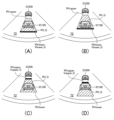
第2車間距離表示制御は、表示制御の1つであって、図6に示したように、メーターディスプレイ72により、所定距離範囲画像RD_G、上限距離ライン画像Dupper_G、下限距離ライン画像Dlower_G、自車両アイコンIC100及び先行車アイコンIC200を表示し、図7に示したように、ヘッドアップディスプレイ71により、所定距離範囲画像RD_G、上限距離ライン画像Dupper_G及び下限距離ライン画像Dlower_Gを表示する制御である。
The second inter-vehicle distance display control is one of the display controls, and as shown in FIG. 6, the
所定距離範囲画像RD_Gは、所定距離範囲RDを表す画像であり、メーターディスプレイ72においては、自車両アイコンIC100が当該所定距離範囲画像RD_G内の位置に存在するように表示され、ヘッドアップディスプレイ71においては、自車両100が当該所定距離範囲画像RD_G内の位置に存在するように表示される。
The specified distance range image RD_G is an image that represents the specified distance range RD, and on the
所定距離範囲画像RD_Gの上側外形線RDupperは、下限距離Dlowerを表しており、所定距離範囲画像RD_Gの下側外形線RDlowerは、上限距離Dupperを表している。又、所定距離範囲画像RD_Gの上下方向の長さ(上側外形線RDupperから下側外形線RDlowerまでの長さ)は、所定距離範囲RDの幅に対応した長さに設定される。従って、所定距離範囲RDの幅が変更された場合、その変更された幅に応じて所定距離範囲画像RD_Gの上下方向の長さが変更される。即ち、所定距離範囲画像RD_Gの上下方向の長さが変更後の所定距離範囲RDの幅に対応するように、所定距離範囲画像RD_Gの上下方向の長さが変更される。 The upper outline RDupper of the specified distance range image RD_G represents the lower limit distance Dlower, and the lower outline RDlower of the specified distance range image RD_G represents the upper limit distance Dupper. In addition, the vertical length of the specified distance range image RD_G (the length from the upper outline RDupper to the lower outline RDlower) is set to a length corresponding to the width of the specified distance range RD. Therefore, when the width of the specified distance range RD is changed, the vertical length of the specified distance range image RD_G is changed according to the changed width. In other words, the vertical length of the specified distance range image RD_G is changed so that it corresponds to the changed width of the specified distance range RD.
又、ヘッドアップディスプレイ71により表示される所定距離範囲画像RD_Gの上側外形線RDupperは、先行車200から後方に下限距離Dlowerだけ離れた位置を示すように表示され、当該所定距離範囲画像RD_Gの下側外形線RDlowerは、先行車200から後方に上限距離Dupperだけ離れた位置を示すように表示される。
In addition, the upper outline RDupper of the specified distance range image RD_G displayed by the head-up
尚、所定距離範囲RDの幅に対応した長さの所定距離範囲画像RD_Gをヘッドアップディスプレイ71により表示しようとすると、図7の(A)に示したように、所定距離範囲画像RD_Gの下側の部分を表示することができないことがある。この場合、所定距離範囲画像RD_Gの下側外形線RDlowerは、ヘッドアップディスプレイ71により表示されているが、上限距離Dupperを表していない。
When attempting to display a predetermined distance range image RD_G with a length corresponding to the width of the predetermined distance range RD on the head-up
又、上限距離ライン画像Dupper_Gは、上限距離Dupperを表す画像であって、所定距離範囲画像RD_Gの下側外形線RDlower上に表示される。又、下限距離ライン画像Dlower_Gは、下限距離Dlowerを表す画像であって、所定距離範囲画像RD_Gの上側外形線RDupper上に表示される。但し、図7の(A)に示したように、所定距離範囲画像RD_Gの下側の部分をヘッドアップディスプレイ71により表示することができない場合、当該所定距離範囲画像RD_Gの下側外形線RDlowerは、上限距離Dupperを表していないので、本例においては、上限距離ライン画像Dupper_Gは、当該所定距離範囲画像RD_Gの下側外形線RDlower上に表示されるが、実線の画像ではなく、鎖線の画像で表示される。
The upper limit distance line image Dupper_G is an image that represents the upper limit distance Dupper, and is displayed on the lower outer line RDlower of the specified distance range image RD_G. The lower limit distance line image Dlower_G is an image that represents the lower limit distance Dlower, and is displayed on the upper outer line RDupper of the specified distance range image RD_G. However, as shown in FIG. 7A, if the lower portion of the specified distance range image RD_G cannot be displayed by the head-up
尚、上限距離ライン画像Dupper_Gは、所定距離範囲画像RD_Gの下側外形線RDlowerよりも太い実線の画像で表示され、下限距離ライン画像Dlower_Gは、所定距離範囲画像RD_Gの上側外形線RDupperよりも太い実線の画像で表示される。 The upper limit distance line image Dupper_G is displayed as an image with a thicker solid line than the lower outline RDlower of the specified distance range image RD_G, and the lower limit distance line image Dlower_G is displayed as an image with a thicker solid line than the upper outline RDupper of the specified distance range image RD_G.
又、自車両アイコンIC100は、自車両100を表す画像であり、所定距離範囲画像RD_Gに重なるように表示される。従って、メーターディスプレイ72において、所定距離範囲画像RD_Gは、自車両アイコンIC100が所定距離範囲画像RD_G内の位置に存在するように表示される。又、先行車アイコンIC200は、先行車200を表す画像であり、メーターディスプレイ72において、自車両アイコンIC100の上側に表示される。
The host vehicle icon IC100 is an image representing the
車両制御装置10は、第2車間距離制御における惰行制御の実行中は、第2車間距離表示制御により、図6の(A)に示したように、所定距離範囲画像RD_G、上限距離ライン画像Dupper_G、自車両アイコンIC100及び先行車アイコンIC200をメーターディスプレイ72により表示する。そして、車両制御装置10は、車間距離Dが上限距離Dupperに達した段階では、図6の(B)に示したように、所定距離範囲画像RD_G、上限距離ライン画像Dupper_G、自車両アイコンIC100及び先行車アイコンIC200をメーターディスプレイ72により表示する。
During execution of coasting control in the second inter-vehicle distance control, the
第2車間距離制御における惰行制御の実行中、自車両アイコンIC100の位置は、メーターディスプレイ72において固定されたままであるが、所定距離範囲画像RD_Gは、車間距離Dが増大するにつれて、その下側外形線RDlowerが自車両アイコンIC100に近づくように、メーターディスプレイ72において上方に移動され、それに伴って、上限距離ライン画像Dupper_Gも、所定距離範囲画像RD_Gの下側外形線RDlower上に表示された状態を保ちながら、自車両アイコンIC100に近づくように、メーターディスプレイ72において上方に移動される。そして、車間距離Dが上限距離Dupperに達した段階では、図6の(B)に示したように、所定距離範囲画像RD_Gの下側外形線RDlower及び上限距離ライン画像Dupper_Gは、自車両アイコンIC100の下端付近に表示される。
During execution of coasting control in the second inter-vehicle distance control, the position of the host vehicle icon IC100 remains fixed on the
一方、車両制御装置10は、第2車間距離制御における最適加速制御の実行中は、第2車間距離表示制御により、図6の(C)に示したように、所定距離範囲画像RD_G、下限距離ライン画像Dlower_G、自車両アイコンIC100及び先行車アイコンIC200をメーターディスプレイ72により表示し、車間距離Dが下限距離Dlowerに達した段階で、図6の(D)に示したように、所定距離範囲画像RD_G、下限距離ライン画像Dlower_G、自車両アイコンIC100及び先行車アイコンIC200をメーターディスプレイ72により表示する。
Meanwhile, while the optimal acceleration control in the second inter-vehicle distance control is being executed, the
第2車間距離制御における最適加速制御の実行中も、自車両アイコンIC100の位置は、メーターディスプレイ72において固定されたままであるが、所定距離範囲画像RD_Gは、車間距離Dが減少するにつれて、その上側外形線RDupperが自車両アイコンIC100に近づくように、メーターディスプレイ72において下方に移動され、それに伴って、下限距離ライン画像Dlower_Gも、所定距離範囲画像RD_Gの上側外形線RDupper上に表示された状態を保ちながら、自車両アイコンIC100に近づくように、メーターディスプレイ72において下方に移動される。そして、車間距離Dが下限距離Dlowerに達した段階では、図6の(D)に示したように、所定距離範囲画像RD_Gの上側外形線RDupper及び下限距離ライン画像Dlower_Gは、自車両アイコンIC100の上端付近に表示される。
Even during the execution of optimal acceleration control in the second inter-vehicle distance control, the position of the host vehicle icon IC100 remains fixed on the
更に、車両制御装置10は、第2車間距離制御における惰行制御の実行中は、第2車間距離表示制御により、図7の(A)に示したように、所定距離範囲画像RD_G及び上限距離ライン画像Dupper_Gをヘッドアップディスプレイ71により表示し、車間距離Dが上限距離Dupperに達した段階では、図7の(B)に示したように、所定距離範囲画像RD_G及び上限距離ライン画像Dupper_Gをヘッドアップディスプレイ71により表示する。
Furthermore, while coasting control is being performed in the second inter-vehicle distance control, the
第2車間距離制御における惰行制御の実行中、車間距離Dが増大するので、自車両100が先行車200から遠ざかる。従って、ヘッドアップディスプレイ71により表示される所定距離範囲画像RD_Gは、車間距離Dが増大するにつれて、その上側外形線RDupperが先行車200から下限距離Dlowerだけ離れた位置を示し続けるように、上方に移動され、それに伴って、図7の(A)に示した例においては、所定距離範囲画像RD_Gの表示面積が徐々に大きくなる。そして、車間距離Dが上限距離Dupperに達した段階では、図7の(B)に示したように、上限距離Dupperを示す所定距離範囲画像RD_Gの下側外形線RDlowerがヘッドアップディスプレイ71に表示されるようになるので、上限距離ライン画像Dupper_Gは、その下側外形線RDlower上に実線の画像で表示される。
During execution of coasting control in the second inter-vehicle distance control, the inter-vehicle distance D increases, so that the
一方、車両制御装置10は、第2車間距離制御における最適加速制御の実行中は、第2車間距離表示制御により、図7の(C)に示したように、所定距離範囲画像RD_G及び下限距離ライン画像Dlower_Gをヘッドアップディスプレイ71により表示し、車間距離Dが下限距離Dlowerに達した段階では、図7の(D)に示したように、所定距離範囲画像RD_G及び下限距離ライン画像Dlower_Gをヘッドアップディスプレイ71により表示する。
Meanwhile, while the optimal acceleration control in the second inter-vehicle distance control is being executed, the
第2車間距離制御における最適加速制御の実行中、車間距離Dが減少するので、自車両100が先行車200に近づく。従って、ヘッドアップディスプレイ71により表示される所定距離範囲画像RD_Gは、車間距離Dが減少するにつれて、その上側外形線RDupperが先行車200から下限距離Dlowerだけ離れた位置を示し続けるように、下方に移動され、それに伴って、図7の(C)に示した例においては、所定距離範囲画像RD_Gの表示面積が徐々に小さくなる。又、所定距離範囲画像RD_Gが下方に移動されるのに伴って、下限距離ライン画像Dlower_Gも、所定距離範囲画像RD_Gの上側外形線RDupper上に表示された状態を保ちながら、下方に移動される。そして、車間距離Dが下限距離Dlowerに達した段階では、所定距離範囲画像RD_G及び下限距離ライン画像Dlower_Gは、図7の(D)に示したように表示される。
During the execution of the optimal acceleration control in the second inter-vehicle distance control, the inter-vehicle distance D decreases, so that the
一方、車両制御装置10は、ステップS340にて「No」と判定した場合、処理をステップS355に進め、第2走行速度制御を実行する。
On the other hand, if the
第2走行速度制御は、自車速Vが上昇して所定の範囲(所定速度範囲RV)の上限値(上限速度Vupper)に達したときに惰行制御を開始し、自車速Vが低下して所定速度範囲RVの下限値(下限速度Vlower)に達したときに最適加速制御を開始することにより、自車速Vが所定速度範囲RV内の速度に維持されるように自車両100の加減速を自律的に制御する制御である。本例において、所定速度範囲RVは、設定速度Vsetを含む範囲に設定される。
The second driving speed control autonomously controls the acceleration/deceleration of the
次いで、車両制御装置10は、処理をステップS360に進め、第2走行速度表示制御を実行し、その後、処理をステップS395に進め、本ルーチンの処理を一旦終了する。
Next, the
第2走行速度表示制御は、表示制御の1つであって、図8に示したように、メーターディスプレイ72により、所定速度範囲画像RV_G、上限速度ライン画像Vupper_G、下限速度ライン画像Vlower_G及び自車両アイコンIC100を表示し、図9に示したように、ヘッドアップディスプレイ71により、所定速度範囲画像RV_G、上限速度ライン画像Vupper_G及び下限速度ライン画像Vlower_Gを表示する制御である。
The second driving speed display control is one of the display controls, and as shown in FIG. 8, the
所定速度範囲画像RV_Gは、所定速度範囲RVを表す画像であり、メーターディスプレイ72においては、自車両アイコンIC100が当該所定速度範囲画像RV_G内の位置に存在するように表示され、ヘッドアップディスプレイ71においては、自車両100が当該所定速度範囲画像RV_G内の位置に存在するように表示される。
The specified speed range image RV_G is an image that represents the specified speed range RV, and on the
所定速度範囲画像RV_Gの上側外形線RVupperは、上限速度Vupperを表しており、所定速度範囲画像RV_Gの下側外形線RVlowerは、下限速度Vlowerを表している。又、所定速度範囲画像RV_Gの上下方向の長さ(上側外形線RVupperから下側外形線RVlowerまでの長さ)は、所定速度範囲RVの幅に対応した長さに設定される。従って、所定速度範囲RVの幅が変更された場合、その変更された幅に応じて所定速度範囲画像RV_Gの上下方向の長さが変更される。即ち、所定速度範囲画像RV_Gの上下方向の長さが変更後の所定速度範囲RVの幅に対応するように、所定速度範囲画像RV_Gの上下方向の長さが変更される。 The upper outline RVupper of the specified speed range image RV_G represents the upper limit speed Vupper, and the lower outline RVlower of the specified speed range image RV_G represents the lower limit speed Vlower. In addition, the vertical length of the specified speed range image RV_G (the length from the upper outline RVupper to the lower outline RVlower) is set to a length corresponding to the width of the specified speed range RV. Therefore, when the width of the specified speed range RV is changed, the vertical length of the specified speed range image RV_G is changed according to the changed width. In other words, the vertical length of the specified speed range image RV_G is changed so that the vertical length of the specified speed range image RV_G corresponds to the width of the changed specified speed range RV.
尚、所定速度範囲RVの幅に対応した長さの所定速度範囲画像RV_Gをヘッドアップディスプレイ71により表示しようとすると、図9の(A)に示したように、所定速度範囲画像RV_Gの下側の部分をヘッドアップディスプレイ71により表示することができないことがある。この場合、所定速度範囲画像RV_Gの下側外形線RVlowerは、ヘッドアップディスプレイ71により表示されているが、下限速度Vlowerを表していない。
When attempting to display a specified speed range image RV_G having a length corresponding to the width of the specified speed range RV on the head-up
又、上限速度ライン画像Vupper_Gは、上限速度Vupperを表す画像であって、所定速度範囲画像RV_Gの上側外形線RVupper上に表示される。又、下限速度ライン画像Vlower_Gは、下限速度Vlowerを表す画像であって、所定速度範囲画像RV_Gの下側外形線RVlower上に表示される。但し、図9の(A)に示したように、所定速度範囲画像RV_Gの下側の部分をヘッドアップディスプレイ71により表示することができない場合、当該所定速度範囲画像RV_Gの下側外形線RVlowerは、下限速度Vlowerを表していないので、本例においては、下限速度ライン画像Vlower_Gは、当該所定速度範囲画像RV_Gの下側外形線RVlower上に表示されるが、実線の画像ではなく、鎖線の画像で表示される。
The upper limit speed line image Vupper_G is an image representing the upper limit speed Vupper, and is displayed on the upper outline RVupper of the specified speed range image RV_G. The lower limit speed line image Vlower_G is an image representing the lower limit speed Vlower, and is displayed on the lower outline RVlower of the specified speed range image RV_G. However, as shown in FIG. 9A, if the lower portion of the specified speed range image RV_G cannot be displayed by the head-up
尚、上限速度ライン画像Vupper_Gは、所定速度範囲画像RV_Gの上側外形線RVupperよりも太い実線の画像で表示され、下限速度ライン画像Vlower_Gは、所定速度範囲画像RV_Gの下側外形線RVlowerよりも太い実線の画像で表示される。 The upper limit speed line image Vupper_G is displayed as a solid line image thicker than the upper outline RVupper of the specified speed range image RV_G, and the lower limit speed line image Vlower_G is displayed as a solid line image thicker than the lower outline RVlower of the specified speed range image RV_G.
又、自車両アイコンIC100は、自車両100を表す画像であり、所定速度範囲画像RV_Gに重なるように表示される。従って、メーターディスプレイ72において、所定速度範囲画像RV_Gは、自車両アイコンIC100が所定速度範囲画像RV_G内の位置に存在するように表示される。
The host vehicle icon IC100 is an image representing the
車両制御装置10は、第2走行速度制御における惰行制御の実行中は、第2走行速度表示制御により、図8の(A)に示したように、所定速度範囲画像RV_G、下限速度ライン画像Vlower_G及び自車両アイコンIC100をメーターディスプレイ72により表示する。そして、車両制御装置10は、自車速Vが下限速度Vlowerに達した段階では、図8の(B)に示したように、所定速度範囲画像RV_G、下限速度ライン画像Vlower_G及び自車両アイコンIC100をメーターディスプレイ72により表示する。
During execution of coasting control in the second driving speed control, the
第2走行速度制御における惰行制御の実行中、自車両アイコンIC100の位置は、メーターディスプレイ72において固定されたままであるが、所定速度範囲画像RV_Gは、自車速Vが低下するにつれて、その下側外形線RVlowerが自車両アイコンIC100に近づくように、メーターディスプレイ72において上方に移動され、それに伴って、下限速度ライン画像Vlower_Gも、所定速度範囲画像RV_Gの下側外形線RVlower上に表示された状態を保ちながら、自車両アイコンIC100に近づくように、メーターディスプレイ72において上方に移動される。そして、自車速Vが下限速度Vlowerに達した段階では、図8の(B)に示したように、所定速度範囲画像RV_Gの下側外形線RVlower及び下限速度ライン画像Vlower_Gは、自車両アイコンIC100の下端付近に表示される。
During execution of coasting control in the second driving speed control, the position of the vehicle icon IC100 remains fixed on the
一方、車両制御装置10は、第2走行速度制御における最適加速制御の実行中は、第2走行速度表示制御により、図8の(C)に示したように、所定速度範囲画像RV_G、上限速度ライン画像Vupper_G及び自車両アイコンIC100をメーターディスプレイ72により表示し、自車速Vが上限速度Vupperに達した段階で、図8の(D)に示したように、所定速度範囲画像RV_G、上限速度ライン画像Vupper_G及び自車両アイコンIC100をメーターディスプレイ72により表示する。
Meanwhile, while the optimal acceleration control in the second driving speed control is being executed, the
第2走行速度制御における最適加速制御の実行中も、自車両アイコンIC100の位置は、メーターディスプレイ72において固定されたままであるが、所定速度範囲画像RV_Gは、自車速Vが上昇するにつれて、その上側外形線RVupperが自車両アイコンIC100に近づくように、メーターディスプレイ72において下方に移動され、それに伴って、上限速度ライン画像Vupper_Gも、所定速度範囲画像RV_Gの上側外形線RVupper上に表示された状態を保ちながら、自車両アイコンIC100に近づくように、メーターディスプレイ72において下方に移動される。そして、自車速Vが上限速度Vupperに達した段階では、図8の(D)に示したように、所定速度範囲画像RV_Gの上側外形線RVupper及び上限速度ライン画像Vupper_Gは、自車両アイコンIC100の上端付近に表示される。
Even during the execution of the optimal acceleration control in the second driving speed control, the position of the vehicle icon IC100 remains fixed on the
更に、車両制御装置10は、第2走行速度制御における惰行制御の実行中は、第2走行速度表示制御により、図9の(A)に示したように、所定速度範囲画像RV_G及び下限速度ライン画像Vlower_Gをヘッドアップディスプレイ71により表示し、自車速Vが下限速度Vlowerに達した段階では、図9の(B)に示したように、所定速度範囲画像RV_G及び下限速度ライン画像Vlower_Gをヘッドアップディスプレイ71により表示する。
Furthermore, while coasting control is being performed in the second driving speed control, the
第2走行速度制御における惰行制御の実行中、自車速Vが低下する。従って、ヘッドアップディスプレイ71により表示される所定速度範囲画像RV_Gは、自車速Vが低下するにつれて、上方に移動され、それに伴って、図9の(A)に示した例においては、所定速度範囲画像RV_Gの表示面積が徐々に大きくなる。そして、自車速Vが下限速度Vlowerに達した段階では、図9の(B)に示したように、下限速度Vlowerを示す所定速度範囲画像RV_Gの下側外形線RVlowerがヘッドアップディスプレイ71に表示されるようになるので、下限速度ライン画像Vlower_Gは、その下側外形線RVlower上に実線の画像で表示される。
During execution of coasting control in the second driving speed control, the vehicle speed V decreases. Therefore, the predetermined speed range image RV_G displayed by the head-up
一方、車両制御装置10は、第2走行速度制御における最適加速制御の実行中は、第2走行速度表示制御により、図9の(C)に示したように、所定速度範囲画像RV_G及び上限速度ライン画像Vupper_Gをヘッドアップディスプレイ71により表示し、自車速Vが上限速度Vupperに達した段階では、図9の(D)に示したように、所定速度範囲画像RV_G及び上限速度ライン画像Vupper_Gをヘッドアップディスプレイ71により表示する。
Meanwhile, while the optimal acceleration control in the second driving speed control is being executed, the
第2走行速度制御における最適加速制御の実行中、自車速Vが上昇する。従って、ヘッドアップディスプレイ71により表示される所定速度範囲画像RV_Gは、自車速Vが上昇するにつれて、下方に移動され、それに伴って、図9の(C)に示した例においては、所定速度範囲画像RV_Gの表示面積が徐々に小さくなる。又、所定速度範囲画像RV_Gが下方に移動されるのに伴って、上限速度ライン画像Vupper_Gも、所定速度範囲画像RV_Gの上側外形線RVupper上に表示された状態を保ちながら、下方に移動される。そして、自車速Vが上限速度Vupperに達した段階では、所定速度範囲画像RV_G及び上限速度ライン画像Vupper_Gは、図9の(D)に示したように表示される。
During execution of optimal acceleration control in the second driving speed control, the vehicle speed V increases. Therefore, the predetermined speed range image RV_G displayed by the head-up
又、車両制御装置10は、ステップS305にて「No」と判定した場合、処理をステップS395に直接進め、本ルーチンの処理を一旦終了する。このとき、自律加減速制御が実行されているときには、当該自律加減速制御は、終了される。
If the
以上が車両制御装置10の作動である。
The above is the operation of the
<効果>
第2走行速度制御の実行中は、自車速Vが所定速度範囲RV内で比較的大きく上下動し、又、第2車間距離制御の実行中は、車間距離Dが所定距離範囲RD内で比較的大きく上下動する。このように自車速V又は車間距離Dが上下動すると、自車速V又は車間距離Dが正常に制御されていないとの誤解を自車両100の操作者に抱かせてしまう可能性がある。
<Effects>
During execution of the second traveling speed control, the vehicle speed V fluctuates up and down relatively greatly within a predetermined speed range RV, and during execution of the second inter-vehicle distance control, the inter-vehicle distance D fluctuates up and down relatively greatly within a predetermined distance range RD. If the vehicle speed V or the inter-vehicle distance D fluctuates up and down in this manner, there is a possibility that the operator of the
車両制御装置10によれば、第2走行速度制御の実行中、当該第2走行速度制御の制御目標である所定速度範囲RVは、自車両100又は自車両アイコンIC100が所定速度範囲画像RV_G内の位置に存在するように表示され、又、第2車間距離制御の実行中、当該第2車間距離制御の制御目標である所定距離範囲RDは、自車両100又は自車両アイコンIC100が所定距離範囲画像RD_G内の位置に存在するように表示される。このため、自車両100の操作者は、自車速V又は車間距離Dが一定の幅のある範囲で制御されていることを理解しやすい。従って、自車速V又は車間距離Dが正常に制御されていないとの誤解を自車両100の操作者に抱かせてしまうことを防止することができる。
According to the
尚、本発明は、上記実施形態に限定されることはなく、本発明の範囲内において種々の変形例を採用することができる。 The present invention is not limited to the above embodiment, and various modifications can be made within the scope of the present invention.
例えば、図2の(B)に示したように、後続車300が存在する場合、車両制御装置10は、第2車間距離制御の実行中、車間距離Dが上限距離Dupperよりも小さいときであっても、自車両100と後続車300との間の距離(後続車間距離DR)が所定距離以下になったときには、最適加速制御により自車両100を加速するように構成されてもよい。この場合、車両制御装置10は、最適加速制御を開始した後、後続車間距離DRが所定距離よりも大きくなっても、車間距離Dが下限距離Dlowerに達するまでは、最適加速制御を継続する。
2B, when a following
又、後続車300が存在する場合、車両制御装置10は、第2車間距離制御の実行中、自車速Vと後続車300の走行速度との差を考慮して自車両100が後続車300に近づき過ぎないように最適加速制御を開始するタイミングを決定するように構成されてもよい。
In addition, when a following
又、車両制御装置10は、自律加減速制御の実行中、ヘッドアップディスプレイ71及びメーターディスプレイ72の両方により、所定距離範囲画像RD_G又は所定速度範囲画像RV_G等の表示を行うが、ヘッドアップディスプレイ71及びメーターディスプレイ72の何れか一方により、所定距離範囲画像RD_G又は所定速度範囲画像RV_G等の表示を行うように構成されてもよい。
In addition, while autonomous acceleration/deceleration control is being performed, the
又、上述した自律加減速制御は、先行車200を対象として、自車両100の加減速を制御する制御であるが、後続車300を含む自車両100の周辺の他車両であって、自車両100の走行方向と同じ方向に走行している他車両(周辺車両)を対象として、自車両100の加減速を制御する制御であってもよい。
The autonomous acceleration/deceleration control described above is a control that controls the acceleration/deceleration of the
10…制御装置(表示制御装置)、20…駆動装置、30…制動装置、60…周辺情報検出装置、70…表示装置、71…ヘッドアップディスプレイ、72…メーターディスプレイ、90…ECU、100…自車両、200…先行車、300…後続車 10...Control device (display control device), 20...Drive device, 30...Braking device, 60...Peripheral information detection device, 70...Display device, 71...Head-up display, 72...Meter display, 90...ECU, 100...Own vehicle, 200...Preceding vehicle, 300...Following vehicle
Claims (2)
前記制御装置は、
前記走行速度制御の実行中、前記自車両又は前記自車両を表す画像が前記所定速度範囲を表す画像内の位置に存在するように前記所定速度範囲を表す画像を前記表示装置により表示し、
前記車間距離制御の実行中、前記自車両又は前記自車両を表す画像が前記所定距離範囲を表す画像内の位置に存在するように前記所定距離範囲を表す画像を表示する、
ように構成されている、
表示制御装置。 a display control device including a control device configured to display an image representing the predetermined speed range on a display device of the host vehicle during execution of a traveling speed control for executing a coasting control for coasting the host vehicle when the traveling speed of the host vehicle increases and reaches an upper limit of a predetermined speed range, and for executing an acceleration control for accelerating the host vehicle when the traveling speed of the host vehicle decreases and reaches a lower limit of the predetermined speed range, or to display an image representing the predetermined distance range on a display device during execution of a vehicle distance control for executing the coasting control when a vehicle-to-vehicle distance between the host vehicle and a surrounding vehicle that is traveling in the same direction as the host vehicle decreases and reaches a lower limit of a predetermined distance range, and for executing the acceleration control when the vehicle-to-vehicle distance increases and reaches an upper limit of the predetermined distance range,
The control device includes:
During execution of the travel speed control, an image representing the predetermined speed range is displayed by the display device so that the host vehicle or an image representing the host vehicle is present at a position within the image representing the predetermined speed range;
During execution of the inter-vehicle distance control, the image representing the predetermined distance range is displayed so that the host vehicle or an image representing the host vehicle is present at a position within the image representing the predetermined distance range.
It is configured as follows:
Display control device.
前記制御装置は、
前記所定速度範囲の幅が変更された場合、当該変更された幅に応じて前記所定速度範囲を表す画像の長さを変更し、
前記所定距離範囲の幅が変更された場合、当該変更された幅に応じて前記所定距離範囲を表す画像の長さを変更する、
ように構成されている、
表示制御装置。 2. The display control device according to claim 1,
The control device includes:
When a width of the predetermined speed range is changed, a length of an image representing the predetermined speed range is changed in accordance with the changed width;
When the width of the predetermined distance range is changed, the length of the image representing the predetermined distance range is changed in accordance with the changed width.
It is configured as follows:
Display control device.
Priority Applications (3)
| Application Number | Priority Date | Filing Date | Title |
|---|---|---|---|
| JP2022201092A JP2024086127A (en) | 2022-12-16 | 2022-12-16 | Display Control Device |
| CN202311722213.0A CN118205391A (en) | 2022-12-16 | 2023-12-13 | Display Controls |
| US18/539,990 US12397791B2 (en) | 2022-12-16 | 2023-12-14 | Displaying control apparatus |
Applications Claiming Priority (1)
| Application Number | Priority Date | Filing Date | Title |
|---|---|---|---|
| JP2022201092A JP2024086127A (en) | 2022-12-16 | 2022-12-16 | Display Control Device |
Publications (1)
| Publication Number | Publication Date |
|---|---|
| JP2024086127A true JP2024086127A (en) | 2024-06-27 |
Family
ID=91454427
Family Applications (1)
| Application Number | Title | Priority Date | Filing Date |
|---|---|---|---|
| JP2022201092A Pending JP2024086127A (en) | 2022-12-16 | 2022-12-16 | Display Control Device |
Country Status (3)
| Country | Link |
|---|---|
| US (1) | US12397791B2 (en) |
| JP (1) | JP2024086127A (en) |
| CN (1) | CN118205391A (en) |
Cited By (1)
| Publication number | Priority date | Publication date | Assignee | Title |
|---|---|---|---|---|
| US12397791B2 (en) * | 2022-12-16 | 2025-08-26 | Toyota Jidosha Kabushiki Kaisha | Displaying control apparatus |
Families Citing this family (1)
| Publication number | Priority date | Publication date | Assignee | Title |
|---|---|---|---|---|
| JP7494830B2 (en) * | 2021-11-10 | 2024-06-04 | トヨタ自動車株式会社 | Vehicle driving support device, vehicle driving support method, vehicle driving support program, and vehicle equipped with vehicle driving support device |
Family Cites Families (54)
| Publication number | Priority date | Publication date | Assignee | Title |
|---|---|---|---|---|
| JP3755248B2 (en) | 1997-07-25 | 2006-03-15 | トヨタ自動車株式会社 | In-vehicle display device |
| JP3838613B2 (en) * | 1999-08-31 | 2006-10-25 | 本田技研工業株式会社 | In-vehicle display device |
| JP2001199262A (en) * | 2000-11-22 | 2001-07-24 | Mitsubishi Motors Corp | Display device in vehicle travel control device |
| JP4066609B2 (en) * | 2001-03-19 | 2008-03-26 | 日産自動車株式会社 | Status display device for vehicle travel control device |
| DE10231687A1 (en) * | 2002-07-10 | 2004-01-22 | Robert Bosch Gmbh | Method and device for notifying the driver of a motor vehicle |
| JP4078907B2 (en) * | 2002-07-22 | 2008-04-23 | 日産自動車株式会社 | Following vehicle display device |
| JP4306764B2 (en) | 2007-06-04 | 2009-08-05 | トヨタ自動車株式会社 | Inter-vehicle distance control device |
| JP4997031B2 (en) | 2007-09-06 | 2012-08-08 | トヨタ自動車株式会社 | Vehicle travel control device |
| JP5108424B2 (en) | 2007-09-06 | 2012-12-26 | トヨタ自動車株式会社 | Vehicle travel control device |
| JP4596016B2 (en) * | 2008-02-12 | 2010-12-08 | トヨタ自動車株式会社 | Vehicle travel control device |
| DE102010016043B4 (en) * | 2009-03-25 | 2021-03-18 | Denso Corporation | Display device and measuring device for a vehicle and method for displaying a vehicle state |
| JP4893771B2 (en) * | 2009-03-30 | 2012-03-07 | アイシン・エィ・ダブリュ株式会社 | Vehicle operation diagnosis device, vehicle operation diagnosis method, and computer program |
| WO2010125634A1 (en) | 2009-04-27 | 2010-11-04 | トヨタ自動車株式会社 | Drive assisting device |
| EP2460706B1 (en) | 2009-07-28 | 2020-05-06 | Toyota Jidosha Kabushiki Kaisha | Vehicle control device, vehicle control method, and vehicle control system |
| EP2461304A4 (en) | 2009-07-28 | 2013-02-27 | DEVICE, METHOD AND CONTROL SYSTEM FOR VEHICLE | |
| DE102009046340A1 (en) * | 2009-11-03 | 2011-05-05 | Zf Friedrichshafen Ag | Method for controlling a rolling or sailing function of a vehicle |
| US8825339B2 (en) * | 2010-09-03 | 2014-09-02 | Toyota Jidosha Kabushiki Kaisha | Vehicular drive control apparatus |
| JP5427202B2 (en) * | 2011-03-29 | 2014-02-26 | 富士重工業株式会社 | Vehicle driving support device |
| JP5427203B2 (en) * | 2011-03-30 | 2014-02-26 | 富士重工業株式会社 | Vehicle driving support device |
| JP5893953B2 (en) * | 2012-02-22 | 2016-03-23 | 日立建機株式会社 | Vehicle operation management system |
| FR3017586B1 (en) * | 2014-02-17 | 2016-02-26 | Peugeot Citroen Automobiles Sa | METHOD AND DEVICE FOR SPEED CONTROL ACCORDING TO ADAPTATION OF THE MAXIMUM SPEED IN THE PRESENCE OF A FOLLOWING VEHICLE |
| WO2016009628A1 (en) * | 2014-07-15 | 2016-01-21 | パナソニックIpマネジメント株式会社 | Vehicular display device |
| JP6363517B2 (en) | 2015-01-21 | 2018-07-25 | 株式会社デンソー | Vehicle travel control device |
| KR101673747B1 (en) * | 2015-02-12 | 2016-11-07 | 현대자동차주식회사 | Apparatus for displaying eco guide in vehicle cluster and method thereof |
| JP6394547B2 (en) | 2015-09-18 | 2018-09-26 | トヨタ自動車株式会社 | Vehicle control device |
| JP6460349B2 (en) * | 2016-04-13 | 2019-01-30 | トヨタ自動車株式会社 | Vehicle travel control device |
| WO2017209313A1 (en) * | 2016-05-30 | 2017-12-07 | 엘지전자 주식회사 | Vehicle display device and vehicle |
| KR101836692B1 (en) * | 2016-09-05 | 2018-03-08 | 현대자동차주식회사 | Auto cruise control method for hybrid electric vehicle |
| JP6592423B2 (en) | 2016-11-25 | 2019-10-16 | 株式会社デンソー | Vehicle control device |
| JP6777518B2 (en) | 2016-11-29 | 2020-10-28 | トヨタ自動車株式会社 | Vehicle control system |
| KR101896801B1 (en) * | 2016-12-08 | 2018-09-07 | 현대자동차주식회사 | Auto cruise control method for hybrid electric vehicle |
| KR20190071097A (en) * | 2017-12-14 | 2019-06-24 | 현대자동차주식회사 | Apparatus and method for controlling display, vehicle system |
| JP7034718B2 (en) * | 2018-01-04 | 2022-03-14 | スタンレー電気株式会社 | Display device for vehicles |
| JP7043965B2 (en) * | 2018-05-09 | 2022-03-30 | スズキ株式会社 | Vehicle information display device |
| KR102726796B1 (en) * | 2019-05-13 | 2024-11-06 | 현대자동차주식회사 | Cruise control method for hybrid electric vehicle |
| DE102019003431A1 (en) * | 2019-05-15 | 2020-11-19 | Daimler Ag | Method for operating a vehicle designed as an automated, in particular highly automated or autonomous driving mode |
| US11268466B2 (en) * | 2019-09-27 | 2022-03-08 | Ford Global Technologies, Llc | Systems and methods for controlling deceleration fuel shut off in response to detection of an external object or location |
| CN216331768U (en) * | 2019-10-23 | 2022-04-19 | 索尼公司 | Display system, display device, and mobile device |
| CN120003472A (en) * | 2020-02-25 | 2025-05-16 | 深圳引望智能技术有限公司 | Method and device for controlling vehicle |
| JP7140153B2 (en) * | 2020-03-03 | 2022-09-21 | トヨタ自動車株式会社 | display controller |
| JP7160065B2 (en) * | 2020-04-16 | 2022-10-25 | トヨタ自動車株式会社 | display controller |
| KR20220036455A (en) * | 2020-09-15 | 2022-03-23 | 현대자동차주식회사 | Apparatus for displaying information of driving based on augmented reality |
| KR20220135900A (en) * | 2021-03-31 | 2022-10-07 | 현대자동차주식회사 | Apparatus for level correction of head lamp and method thereof |
| JP2023072773A (en) * | 2021-11-15 | 2023-05-25 | 本田技研工業株式会社 | Driving assistance device |
| JP7601017B2 (en) * | 2022-01-27 | 2024-12-17 | トヨタ自動車株式会社 | Vehicle Driving Assistance Device |
| US20240101121A1 (en) * | 2022-09-22 | 2024-03-28 | Tusimple, Inc. | Controlling driving modes and operations for vehicles |
| JP2024062032A (en) * | 2022-10-24 | 2024-05-09 | トヨタ自動車株式会社 | Vehicle running device |
| JP2024062033A (en) * | 2022-10-24 | 2024-05-09 | トヨタ自動車株式会社 | Vehicle running device |
| JP2024086125A (en) * | 2022-12-16 | 2024-06-27 | トヨタ自動車株式会社 | Display Control Device |
| JP2024086127A (en) * | 2022-12-16 | 2024-06-27 | トヨタ自動車株式会社 | Display Control Device |
| JP2024100030A (en) * | 2023-01-13 | 2024-07-26 | トヨタ自動車株式会社 | Vehicle Driving Assistance Device |
| JP7800466B2 (en) * | 2023-01-20 | 2026-01-16 | トヨタ自動車株式会社 | Vehicle display control device, vehicle, vehicle display control method and program |
| JP2025063768A (en) * | 2023-10-04 | 2025-04-16 | トヨタ自動車株式会社 | Vehicle display device, vehicle display method, and program |
| JP2025064160A (en) * | 2023-10-05 | 2025-04-17 | トヨタ自動車株式会社 | DISPLAY CONTROL DEVICE, VEHICLE EQUIPPED WITH DISPLAY CONTROL DEVICE, DISPLAY CONTROL METHOD, AND DISPLAY CONTROL PROGRAM |
-
2022
- 2022-12-16 JP JP2022201092A patent/JP2024086127A/en active Pending
-
2023
- 2023-12-13 CN CN202311722213.0A patent/CN118205391A/en active Pending
- 2023-12-14 US US18/539,990 patent/US12397791B2/en active Active
Cited By (1)
| Publication number | Priority date | Publication date | Assignee | Title |
|---|---|---|---|---|
| US12397791B2 (en) * | 2022-12-16 | 2025-08-26 | Toyota Jidosha Kabushiki Kaisha | Displaying control apparatus |
Also Published As
| Publication number | Publication date |
|---|---|
| CN118205391A (en) | 2024-06-18 |
| US20240199055A1 (en) | 2024-06-20 |
| US12397791B2 (en) | 2025-08-26 |
Similar Documents
| Publication | Publication Date | Title |
|---|---|---|
| JP6988908B2 (en) | Control method and control device for self-driving vehicles | |
| JP6437891B2 (en) | Automotive control device | |
| CN103523016A (en) | Method for operating a vehicle during coasting | |
| US12397791B2 (en) | Displaying control apparatus | |
| US20230150464A1 (en) | Vehicle control device | |
| JP2023091170A (en) | Driving state judgment method, automatic driving system | |
| US20240227801A9 (en) | Vehicle moving apparatus | |
| US20240227806A9 (en) | Vehicle moving apparatus | |
| US20240239339A1 (en) | Vehicle driving assistance apparatus | |
| US20240227807A9 (en) | Vehicle moving control apparatus, vehicle moving control method, and computer-readable storage medium storing vehicle moving control program | |
| US20240190430A1 (en) | Vehicle driving assistance apparatus, vehicle driving assistance method, and computer-readable storage medium storing vehicle driving assistance program | |
| WO2024127922A1 (en) | Display control device | |
| CN112550288A (en) | Vehicle driving assistance device | |
| CN116241647A (en) | Speed change control device, speed change control method, and computer program for speed change control | |
| JP6988907B2 (en) | Vehicle control method and control device | |
| EP4699882A1 (en) | Vehicle driver assistance device, vehicle driver assistance method, and non-transitory storage medium | |
| JP7841501B2 (en) | Autonomous driving system | |
| JP7740289B2 (en) | Vehicle driving assistance device | |
| JP2021115989A (en) | On-vehicle camera control device | |
| JP7750668B2 (en) | Vehicle control device, control method, and control program | |
| JP2025086744A (en) | Vehicle Driving Assistance Device | |
| JP2025068830A (en) | Vehicle travel support device | |
| JP2026013148A (en) | Vehicle driving assistance device, vehicle driving assistance method, and vehicle driving assistance program | |
| JP2026068285A (en) | Vehicle driving assistance system | |
| CN121822466A (en) | Vehicle driving assistance devices |
Legal Events
| Date | Code | Title | Description |
|---|---|---|---|
| A621 | Written request for application examination |
Free format text: JAPANESE INTERMEDIATE CODE: A621 Effective date: 20251008 |