JP2024075558A - Electrical Connection Device - Google Patents
Electrical Connection Device Download PDFInfo
- Publication number
- JP2024075558A JP2024075558A JP2023198271A JP2023198271A JP2024075558A JP 2024075558 A JP2024075558 A JP 2024075558A JP 2023198271 A JP2023198271 A JP 2023198271A JP 2023198271 A JP2023198271 A JP 2023198271A JP 2024075558 A JP2024075558 A JP 2024075558A
- Authority
- JP
- Japan
- Prior art keywords
- conductive member
- conductor
- rear end
- outer conductor
- electrical connection
- Prior art date
- Legal status (The legal status is an assumption and is not a legal conclusion. Google has not performed a legal analysis and makes no representation as to the accuracy of the status listed.)
- Granted
Links
Images


Classifications
-
- H—ELECTRICITY
- H01—ELECTRIC ELEMENTS
- H01R—ELECTRICALLY-CONDUCTIVE CONNECTIONS; STRUCTURAL ASSOCIATIONS OF A PLURALITY OF MUTUALLY-INSULATED ELECTRICAL CONNECTING ELEMENTS; COUPLING DEVICES; CURRENT COLLECTORS
- H01R13/00—Details of coupling devices of the kinds covered by groups H01R12/70 or H01R24/00 - H01R33/00
- H01R13/62—Means for facilitating engagement or disengagement of coupling parts or for holding them in engagement
- H01R13/627—Snap or like fastening
- H01R13/6271—Latching means integral with the housing
-
- H—ELECTRICITY
- H01—ELECTRIC ELEMENTS
- H01R—ELECTRICALLY-CONDUCTIVE CONNECTIONS; STRUCTURAL ASSOCIATIONS OF A PLURALITY OF MUTUALLY-INSULATED ELECTRICAL CONNECTING ELEMENTS; COUPLING DEVICES; CURRENT COLLECTORS
- H01R13/00—Details of coupling devices of the kinds covered by groups H01R12/70 or H01R24/00 - H01R33/00
- H01R13/648—Protective earth or shield arrangements on coupling devices, e.g. anti-static shielding
- H01R13/658—High frequency shielding arrangements, e.g. against EMI [Electro-Magnetic Interference] or EMP [Electro-Magnetic Pulse]
- H01R13/6581—Shield structure
- H01R13/6582—Shield structure with resilient means for engaging mating connector
-
- H—ELECTRICITY
- H01—ELECTRIC ELEMENTS
- H01R—ELECTRICALLY-CONDUCTIVE CONNECTIONS; STRUCTURAL ASSOCIATIONS OF A PLURALITY OF MUTUALLY-INSULATED ELECTRICAL CONNECTING ELEMENTS; COUPLING DEVICES; CURRENT COLLECTORS
- H01R13/00—Details of coupling devices of the kinds covered by groups H01R12/70 or H01R24/00 - H01R33/00
- H01R13/46—Bases; Cases
- H01R13/502—Bases; Cases composed of different pieces
-
- H—ELECTRICITY
- H01—ELECTRIC ELEMENTS
- H01R—ELECTRICALLY-CONDUCTIVE CONNECTIONS; STRUCTURAL ASSOCIATIONS OF A PLURALITY OF MUTUALLY-INSULATED ELECTRICAL CONNECTING ELEMENTS; COUPLING DEVICES; CURRENT COLLECTORS
- H01R13/00—Details of coupling devices of the kinds covered by groups H01R12/70 or H01R24/00 - H01R33/00
- H01R13/02—Contact members
- H01R13/20—Pins, blades, or sockets shaped, or provided with separate member, to retain co-operating parts together
-
- H—ELECTRICITY
- H01—ELECTRIC ELEMENTS
- H01R—ELECTRICALLY-CONDUCTIVE CONNECTIONS; STRUCTURAL ASSOCIATIONS OF A PLURALITY OF MUTUALLY-INSULATED ELECTRICAL CONNECTING ELEMENTS; COUPLING DEVICES; CURRENT COLLECTORS
- H01R13/00—Details of coupling devices of the kinds covered by groups H01R12/70 or H01R24/00 - H01R33/00
- H01R13/62—Means for facilitating engagement or disengagement of coupling parts or for holding them in engagement
- H01R13/639—Additional means for holding or locking coupling parts together, after engagement, e.g. separate keylock, retainer strap
-
- H—ELECTRICITY
- H01—ELECTRIC ELEMENTS
- H01R—ELECTRICALLY-CONDUCTIVE CONNECTIONS; STRUCTURAL ASSOCIATIONS OF A PLURALITY OF MUTUALLY-INSULATED ELECTRICAL CONNECTING ELEMENTS; COUPLING DEVICES; CURRENT COLLECTORS
- H01R24/00—Two-part coupling devices, or either of their cooperating parts, characterised by their overall structure
- H01R24/005—Two-part coupling devices, or either of their cooperating parts, characterised by their overall structure requiring successive relative motions to complete the coupling, e.g. bayonet type
-
- H—ELECTRICITY
- H01—ELECTRIC ELEMENTS
- H01R—ELECTRICALLY-CONDUCTIVE CONNECTIONS; STRUCTURAL ASSOCIATIONS OF A PLURALITY OF MUTUALLY-INSULATED ELECTRICAL CONNECTING ELEMENTS; COUPLING DEVICES; CURRENT COLLECTORS
- H01R24/00—Two-part coupling devices, or either of their cooperating parts, characterised by their overall structure
- H01R24/38—Two-part coupling devices, or either of their cooperating parts, characterised by their overall structure having concentrically or coaxially arranged contacts
-
- H—ELECTRICITY
- H01—ELECTRIC ELEMENTS
- H01R—ELECTRICALLY-CONDUCTIVE CONNECTIONS; STRUCTURAL ASSOCIATIONS OF A PLURALITY OF MUTUALLY-INSULATED ELECTRICAL CONNECTING ELEMENTS; COUPLING DEVICES; CURRENT COLLECTORS
- H01R2103/00—Two poles
-
- H—ELECTRICITY
- H01—ELECTRIC ELEMENTS
- H01R—ELECTRICALLY-CONDUCTIVE CONNECTIONS; STRUCTURAL ASSOCIATIONS OF A PLURALITY OF MUTUALLY-INSULATED ELECTRICAL CONNECTING ELEMENTS; COUPLING DEVICES; CURRENT COLLECTORS
- H01R24/00—Two-part coupling devices, or either of their cooperating parts, characterised by their overall structure
- H01R24/38—Two-part coupling devices, or either of their cooperating parts, characterised by their overall structure having concentrically or coaxially arranged contacts
- H01R24/40—Two-part coupling devices, or either of their cooperating parts, characterised by their overall structure having concentrically or coaxially arranged contacts specially adapted for high frequency
- H01R24/50—Two-part coupling devices, or either of their cooperating parts, characterised by their overall structure having concentrically or coaxially arranged contacts specially adapted for high frequency mounted on a PCB [Printed Circuit Board]
Landscapes
- Details Of Connecting Devices For Male And Female Coupling (AREA)
- Coupling Device And Connection With Printed Circuit (AREA)
Abstract
Description
本出願は、2022年11月23日に出願された「電気接続装置」という名称の中国特許出願第202211471880.1の利益及び優先権を主張するものであり、その全内容は参照によって本明細書に組み込まれる。 This application claims the benefit of and priority to Chinese Patent Application No. 202211471880.1, entitled "Electrical Connection Device", filed on November 23, 2022, the entire contents of which are incorporated herein by reference.
本発明は、電気接続装置に関し、特に、同軸コネクタが嵌合コネクタと嵌合する電気接続装置に関する。 The present invention relates to an electrical connection device, and in particular to an electrical connection device in which a coaxial connector mates with a mating connector.
既存のマイクロミニチュア同軸(MMCX)コネクタは、一般に、嵌合コネクタにロックされるラッチ構造として作用するC字型ラッチリングによって導電体にラッチする。 Existing microminiature coaxial (MMCX) connectors typically latch onto the conductors with a C-shaped latch ring that acts as a latch structure that locks into the mating connector.
マイクロミニチュア同軸コネクタが嵌合コネクタと嵌合し、振動しているとき、C字型ラッチリングと導電体との間に間隙があるため、C字型ラッチリング及び導電体は、電流又は信号を伝達する際に、電力の瞬断又は信号の中断を非常に生じやすく、これにより、C字型ラッチリング及び導電体の機能が損なわれる。導電体と嵌合コネクタとの間にも間隙があるため、マイクロミニチュア同軸コネクタが嵌合コネクタに対して非常に揺動しやすくなり、伝達の安定性が良くなくなる。更に、C字型ラッチリングの長さが短く、C字型ラッチリングの弾性が良好ではないため、マイクロミニチュア同軸コネクタの繰り返しの挿入及び引き抜きのプロセスにおいて、C字型ラッチリングは、弾性疲労を生じやすく、C字型ラッチリングを変形させ、その結果、伝達の安定性が影響を受け、電力の瞬断又は信号の中断さえ生じる。上記のような理由に基づいて、既存のマイクロミニチュア同軸コネクタ、例えば、中国特許第207504225(U)号に開示されたコネクタは、電流を印加することを必要とし、かつ伝達を行う環境、例えば、音源機器又は自動車バックミラー疲労検出などに適用することができない。 When the micro-miniature coaxial connector is mated with the mating connector and vibrating, there is a gap between the C-shaped latch ring and the conductor, so that the C-shaped latch ring and the conductor are very likely to cause power interruption or signal interruption when transmitting current or signal, which impairs the function of the C-shaped latch ring and the conductor. There is also a gap between the conductor and the mating connector, so that the micro-miniature coaxial connector is very likely to swing relative to the mating connector, which leads to poor stability of transmission. In addition, because the length of the C-shaped latch ring is short and the elasticity of the C-shaped latch ring is not good, in the process of repeated insertion and withdrawal of the micro-miniature coaxial connector, the C-shaped latch ring is prone to elastic fatigue, which causes the C-shaped latch ring to deform, which affects the stability of transmission and even causes power interruption or signal interruption. For the reasons mentioned above, existing microminiature coaxial connectors, such as the connector disclosed in China Patent No. 207504225 (U), cannot be applied to environments that require current application and transmission, such as sound source equipment or automobile rearview mirror fatigue detection.
電力の瞬断又は信号の中断の問題を克服するために、いくつかのコネクタ、例えば、中国特許第209786238(U)号に開示されたコネクタは、マイクロミニチュア同軸コネクタの前端にラッチ構造を提供する。しかしながら、このような構造は、MMCX規格に準拠した既存の嵌合コネクタには適用することができない。したがって、新たな嵌合コネクタを再設計してマッチングを行うことになり、製造コストが増大する。 To overcome the problem of power interruption or signal interruption, some connectors, such as the connector disclosed in CN Patent No. 209786238(U), provide a latch structure at the front end of the microminiature coaxial connector. However, such a structure cannot be applied to existing mating connectors that comply with the MMCX standard. Therefore, new mating connectors have to be redesigned to match, which increases manufacturing costs.
したがって、本開示の目的は、従来技術における少なくとも1つの欠点を改善することができる、電気接続装置を提供することである。 Therefore, an object of the present disclosure is to provide an electrical connection device that can improve at least one of the shortcomings in the prior art.
したがって、本開示の電気接続装置は、プラグコネクタを含む。プラグコネクタは、導電体、外部導体、絶縁体、及び中心端子を含む。外部導体は、後端、少なくとも1つの前方ラッチ部分、及び少なくとも1つの弾性片を有する。後端は、導電体を電気的に接続し、前方ラッチ部分は、後端に対向して後端の前方に位置し、弾性片は、後端と前方ラッチ部分との間に位置して前方ラッチ部分を接続する。導電体及び外部導体のうちの少なくとも1つには係止面が形成され、係止面の位置は、外部導体の弾性片に対応し、前方ラッチ部分に近接する。絶縁体は、導電体内に設けられる。中心端子は、絶縁体内に設けられる。 Thus, the electrical connection device of the present disclosure includes a plug connector. The plug connector includes a conductor, an outer conductor, an insulator, and a center terminal. The outer conductor has a rear end, at least one front latch portion, and at least one elastic piece. The rear end electrically connects the conductor, the front latch portion is located opposite the rear end and forward of the rear end, and the elastic piece is located between the rear end and the front latch portion to connect the front latch portion. At least one of the conductor and the outer conductor is formed with a locking surface, and the position of the locking surface corresponds to the elastic piece of the outer conductor and is adjacent to the front latch portion. The insulator is provided within the conductor. The center terminal is provided within the insulator.
いくつかの実施形態では、弾性片は、係止面が形成される。 In some embodiments, the elastic piece is formed with a locking surface.
いくつかの実施形態では、弾性片は、肩部を有する。肩部は、肩部面を有する。肩部面は、係止面を形成する。 In some embodiments, the elastic piece has a shoulder. The shoulder has a shoulder surface. The shoulder surface forms a locking surface.
いくつかの実施形態では、導電体は、前方に延在し、かつ弾性片を取り囲む環状周囲壁を有する。環状周囲壁は、前端面を有し、前端面は、係止面を形成する。 In some embodiments, the electrical conductor has an annular peripheral wall that extends forward and surrounds the resilient piece. The annular peripheral wall has a front end surface that forms the locking surface.
いくつかの実施形態では、弾性片は、肩部を有する。肩部は、肩部面を有する。導電体は、前方に延在し、かつ弾性片を取り囲む環状周囲壁を有する。環状周囲壁は、前端面を有する。肩部面及び前端面は係止面を一緒に形成する。 In some embodiments, the resilient piece has a shoulder. The shoulder has a shoulder surface. The conductor has an annular peripheral wall that extends forward and surrounds the resilient piece. The annular peripheral wall has a front end surface. The shoulder surface and the front end surface together form a locking surface.
いくつかの実施形態では、外部導体は、少なくとも1つのスリットが形成される。スリットは、前方ラッチ部分から後端に近接するように延在する。スリットは、前方ラッチ部分に位置する開口部と、開口部分に対向して後端に近接する閉鎖部分とを有する。 In some embodiments, the outer conductor is formed with at least one slit. The slit extends from the forward latch portion proximate the rear end. The slit has an opening located at the forward latch portion and a closed portion opposite the opening portion proximate the rear end.
いくつかの実施形態では、外部導体は、複数の前方ラッチ部分及び複数の弾性片を有し、複数のスリットが形成されている。各スリットは、2つの対応する隣接する前方ラッチ部分から後端に近接するように延在する。各スリットは、対応する2つの隣接する前方ラッチ部分の間、及び対応する2つの隣接する弾性片の間に位置する。 In some embodiments, the outer conductor has a plurality of forward latch portions and a plurality of resilient pieces, and a plurality of slits are formed. Each slit extends from two corresponding adjacent forward latch portions proximate to the rear end. Each slit is located between two corresponding adjacent forward latch portions and between two corresponding adjacent resilient pieces.
いくつかの実施形態では、外部導体は、貫通間隙が更に形成される。貫通間隙は、2つの対応する隣接する前方ラッチ部分から後端まで延在する。貫通間隙は、2つのスルー開口部を有する。2つのスルー開口部は、2つの対応する隣接する前方ラッチ部分の間及び後端にそれぞれ位置する。 In some embodiments, the outer conductor further includes a through gap formed therein. The through gap extends from the two corresponding adjacent front latch portions to the rear end. The through gap has two through openings. The two through openings are located between the two corresponding adjacent front latch portions and at the rear end, respectively.
いくつかの実施形態では、外部導体は、貫通間隙が形成される。貫通間隙は、前方ラッチ部から後端まで延在する。貫通間隙は、前方ラッチ部分及び後端にそれぞれ位置する2つのスルー開口部を有する。 In some embodiments, the outer conductor is formed with a through gap. The through gap extends from the forward latch portion to the rear end. The through gap has two through openings, one located at the forward latch portion and the other located at the rear end.
いくつかの実施形態では、導電体は、一体型コンポーネントであり、外側に開口する環状凹溝が形成される。外部導体は、導電体を覆い、貫通間隙が形成される。貫通間隙は、前方ラッチ部分から後端まで延在する。外部導体は、後端に接続された内側フランジを有する。内側フランジは、環状凹溝にスナップ嵌めされ、弾性力を印加して導電体をクランプする。 In some embodiments, the conductor is a one-piece component and has an annular groove that opens outward. The outer conductor covers the conductor and has a through gap. The through gap extends from the forward latch portion to the rear end. The outer conductor has an inner flange connected to the rear end. The inner flange snaps into the annular groove and applies a resilient force to clamp the conductor.
いくつかの実施形態では、導電体は、一体型コンポーネントである。外部導体の後端は、導電体に一体的に接続される。外部導体及び導電体は、一体的に形成されて一体型コンポーネントを一緒に構成する。絶縁体は、導電体及び外部導体に提供された提供セグメントと、提供セグメントの前端に形成され、前方ラッチ部分の前端から突出するヘッドセグメントとを有する。 In some embodiments, the conductor is an integral component. The rear end of the outer conductor is integrally connected to the conductor. The outer conductor and the conductor are integrally formed to together constitute an integral component. The insulator has a presentation segment that is presented to the conductor and the outer conductor, and a head segment that is formed at a front end of the presentation segment and that projects from a front end of the forward latch portion.
いくつかの実施形態では、導電体は、一体型コンポーネントであり得、前方に開口する環状チャネルが形成される。外部導体には、前方ラッチ部分から後端まで延在する貫通間隙が形成される。外部導体は、導電体を覆い、弾性力を印加して導電体をクランプする。後端及び弾性片は、環状チャネル内に収容され、前方ラッチ部分は、環状チャネルから露出される。 In some embodiments, the electrical conductor may be a one-piece component and is formed with a forwardly opening annular channel. The outer conductor is formed with a through gap extending from the forward latch portion to the rear end. The outer conductor covers the electrical conductor and applies a resilient force to clamp the electrical conductor. The rear end and the resilient piece are received within the annular channel and the forward latch portion is exposed from the annular channel.
いくつかの実施形態では、外部導体は、複数の前方ラッチ部分及び複数の弾性片を有し、複数のスリットが形成される。貫通間隙は、2つの対応する隣接する前方ラッチ部分から後端まで延在する。各スリットは、2つの対応する隣接する前方ラッチ部分から後端に近接するように延在する。各スリットは、対応する2つの隣接する前方ラッチ部分の間、及び対応する2つの隣接する弾性片の間に位置する。各弾性片は、対応する前方ラッチ部分に接続された第1の弾性片本体と、第1の弾性片本体から後方に延在して導電体に当接する弾性力を印加する第2の弾性片本体とを有する。 In some embodiments, the outer conductor has a plurality of front latch portions and a plurality of elastic pieces, and a plurality of slits are formed. The through gap extends from two corresponding adjacent front latch portions to the rear end. Each slit extends from two corresponding adjacent front latch portions to proximate the rear end. Each slit is located between the corresponding two adjacent front latch portions and between the corresponding two adjacent elastic pieces. Each elastic piece has a first elastic piece body connected to the corresponding front latch portion and a second elastic piece body extending rearward from the first elastic piece body to apply an elastic force that abuts against the conductor.
いくつかの実施形態では、導電体は、一体型コンポーネントであり、前方に開口する環状チャネルが形成される。外部導体は、後端に接続された外側フランジを更に有する。外部導体は、導電体及び後端を覆い、外側フランジは、環状チャネル内に受容される。導電体は、前方に延在して環状チャネルを取り囲む環状ラッチ押圧壁を有する。環状ラッチ押圧壁の前端は、内側に曲がるように変形され、外側フランジにラッチして押圧する。 In some embodiments, the conductor is a one-piece component and defines an annular channel that opens forward. The outer conductor further has an outer flange connected to the rear end. The outer conductor covers the conductor and the rear end, and the outer flange is received within the annular channel. The conductor has an annular latch pressure wall that extends forward and surrounds the annular channel. The front end of the annular latch pressure wall is deformed to bend inwardly and latch onto and press against the outer flange.
いくつかの実施形態では、導電体は、第1の導電部材と、第1の導電部材内に設けられ、第1の導電部材の前端から部分的に突出する第2の導電部材とを有する。第1の導電部材及び第2の導電部材は、前方に開口する環状チャンネルを一緒に画定する。外部導体は、後端に接続された外側フランジを更に有する。後端、弾性片、及び外側フランジは、環状チャネル内に収容される。前方ラッチ部分は、環状チャネルから露出し、第1の導電部材の前端から突出する。外側フランジは、第1の導電部材及び第2の導電部材によってクランプされる。 In some embodiments, the electrical conductor has a first conductive member and a second conductive member disposed within the first conductive member and partially projecting from a front end of the first conductive member. The first conductive member and the second conductive member together define a forwardly opening annular channel. The outer conductor further has an outer flange connected to the rear end. The rear end, the resilient piece, and the outer flange are received within the annular channel. A forward latch portion is exposed from the annular channel and projects from the front end of the first conductive member. The outer flange is clamped by the first conductive member and the second conductive member.
いくつかの実施形態では、導電体は、第1の導電部材と、第1の導電部材内に設けられ、第1の導電部材の前端から部分的に突出する第2の導電部材と、第1の導電部材内に設けられ、第1の導電部材の後端から部分的に突出する第3の導電部材とを有する。第1の導電部材及び第2の導電部材は、前方に開口する環状チャンネルを一緒に画定する。外部導体は、外部導体の後端に接続された外側フランジを更に有する。外部導体の後端、弾性片、及び外側フランジは、環状チャネル内に収容される。前方ラッチ部分は、環状チャネルから露出し、第1の導電部材の前端から突出する。外側フランジは、第1の導電部材及び第2の導電部材によってクランプされる。 In some embodiments, the conductor has a first conductive member, a second conductive member disposed within the first conductive member and partially protruding from a front end of the first conductive member, and a third conductive member disposed within the first conductive member and partially protruding from a rear end of the first conductive member. The first conductive member and the second conductive member together define a forwardly opening annular channel. The outer conductor further has an outer flange connected to the rear end of the outer conductor. The rear end of the outer conductor, the resilient piece, and the outer flange are received within the annular channel. A forward latch portion is exposed from the annular channel and protrudes from the front end of the first conductive member. The outer flange is clamped by the first conductive member and the second conductive member.
いくつかの実施形態では、導電体は、第1の導電部材及び第2の導電部材を有する。外部導体の後端は、第1の導電部材に一体的に接続される。外部導体及び第1の導電部材は、一体的に形成されて一体型コンポーネントを一緒に構成する。第2の導電部材は、第1の導電部材及び外部導体内に設けられ、前方ラッチ部分の前端から部分的に突出する。 In some embodiments, the electrical conductor has a first conductive member and a second conductive member. The rear end of the outer conductor is integrally connected to the first conductive member. The outer conductor and the first conductive member are integrally formed to together define an integral component. The second conductive member is disposed within the first conductive member and the outer conductor and partially protrudes from the front end of the forward latch portion.
いくつかの実施形態では、導電体は、第1の導電部材及び第2の導電部材を有する。外部導体の後端は、第1の導電部材に一体的に接続される。外部導体及び第1の導電部材は、一体的に形成されて一体型コンポーネントを一緒に構成する。第2の導電部材は、第1の導電部材及び外部導体内に設けられ、前方ラッチ部分の前端から部分的に突出する。絶縁体は、第2の導電部材に提供された提供セグメントと、提供セグメントの前端に形成され、第2の導電部材の前端から突出するヘッドセグメントとを有する。 In some embodiments, the electrical conductor has a first conductive member and a second conductive member. The rear end of the outer conductor is integrally connected to the first conductive member. The outer conductor and the first conductive member are integrally formed to together constitute an integral component. The second conductive member is disposed within the first conductive member and the outer conductor and partially projects from the front end of the forward latch portion. The insulator has a providing segment provided to the second conductive member and a head segment formed at a front end of the providing segment and projecting from the front end of the second conductive member.
いくつかの実施形態では、導電体は、第1の導電部材及び第2の導電部材を有する。外部導体の後端は、第1の導電部材に一体的に接続される。外部導体及び第1の導電部材は、一体的に形成されて一体型コンポーネントを一緒に構成する。第2の導電部材は、第1の導電部材及び外部導体内に設けられ、前方ラッチ部分の前端から部分的に突出し、第1の導電部材は、第2の導電部材に干渉する内側干渉円周方向壁を有する。 In some embodiments, the electrical conductor has a first conductive member and a second conductive member. The rear end of the outer conductor is integrally connected to the first conductive member. The outer conductor and the first conductive member are integrally formed to together define an integral component. The second conductive member is disposed within the first conductive member and the outer conductor and partially protrudes from the front end of the forward latch portion, the first conductive member having an inner interference circumferential wall that interferes with the second conductive member.
いくつかの実施形態では、導電体は、第1の導電部材と、第1の導電部材内に設けられ、第1の導電部材の前端から部分的に突出する第2の導電部材とを有する。第1の導電部材は、内側干渉円周方向壁を有する。第2導電部材は、内側干渉円周方向壁に干渉し、外側に開口する環状凹溝が形成される。第1の導電部材及び第2の導電部材は、前方に開口して環状凹溝に連通する環状チャネルを一緒に画定する。外部導体は、第2の導電部材を覆い、貫通間隙が形成されてもよい。貫通間隙は、前方ラッチ部分から後端まで延在する。外部導体は、後端に接続された内側フランジを更に有する。後端、弾性片、及び内側フランジは、環状チャネル内に収容される。前方ラッチ部分は、環状チャネルから露出している。内側フランジは、環状凹溝にスナップ嵌めされ、弾性力を印加して第2の導電部材をクランプする。 In some embodiments, the conductor has a first conductive member and a second conductive member disposed within the first conductive member and partially protruding from a front end of the first conductive member. The first conductive member has an inner interference circumferential wall. The second conductive member interferes with the inner interference circumferential wall, and an annular groove opening to the outside is formed. The first conductive member and the second conductive member together define an annular channel opening forward and communicating with the annular groove. The outer conductor may cover the second conductive member, and a through gap may be formed. The through gap extends from the forward latch portion to the rear end. The outer conductor further has an inner flange connected to the rear end. The rear end, the elastic piece, and the inner flange are received in the annular channel. The forward latch portion is exposed from the annular channel. The inner flange is snap-fitted into the annular groove and applies an elastic force to clamp the second conductive member.
いくつかの実施形態では、前方ラッチ部分の前端は、前方当接面を有する。 In some embodiments, the front end of the forward latch portion has a forward abutment surface.
いくつかの実施形態では、前方ラッチ部分は突起である。中心端子は、オス端子である。電気接続装置は、レセプタクルコネクタを更に含む。レセプタクルコネクタは、外殻と、外殻内に設けられる絶縁体と、絶縁体内に設けられ、中心端子を電気的に接続するために使用されるメス端子とを含む。外殻には、前方ラッチ部をそこにラッチすることを可能するために使用される内側環状溝が形成される。外殻は、係止面をそこに当接させるために使用される嵌合端面を有する。プラグコネクタがレセプタクルコネクタと嵌合するとき、前方ラッチ部分は、内側環状溝にラッチする。係止面は、嵌合端面にしっかりと当接する。 In some embodiments, the forward latch portion is a protrusion. The center terminal is a male terminal. The electrical connection device further includes a receptacle connector. The receptacle connector includes an outer shell, an insulator disposed within the outer shell, and a female terminal disposed within the insulator and used to electrically connect the center terminal. The outer shell is formed with an inner annular groove that is used to enable the forward latch portion to be latched therein. The outer shell has a mating end face that is used to abut a locking surface thereon. When the plug connector is mated with the receptacle connector, the forward latch portion latches into the inner annular groove. The locking surface firmly abuts the mating end face.
いくつかの実施形態では、外殻は、内側環状溝を取り囲む前方内側円錐面を更に有し、嵌合端面から離間され、嵌合端面の前方に位置付けられる。前方ラッチ部分は円弧面を有し、プラグコネクタがレセプタクルコネクタと嵌合するとき、円弧面は、係止面を嵌合端面に対してしっかりと当接させることを促進するために、前方内側円錐面にラッチして前方内側円錐面に推力を印加する。 In some embodiments, the shell further includes a forward inner conical surface surrounding the inner annular groove and spaced apart from and positioned forward of the mating end face. The forward latch portion includes an arcuate surface that latches against and applies a thrust to the forward inner conical surface to facilitate firm abutment of the locking surface against the mating end face when the plug connector is mated with the receptacle connector.
いくつかの実施形態では、外殻は、前方内側円錐面から離間している前方係止面を更に有し、前方内側円錐面の前方に位置し、内側環状溝を取り囲む。前方ラッチ部分は、円弧面の前端に接続される前方当接面を更に有し、前方係止面に当接するために使用される。プラグコネクタがレセプタクルコネクタと嵌合するとき、前方当接面は前方係止面にしっかりと当接する。 In some embodiments, the shell further includes a forward locking surface spaced apart from the forward inner conical surface, located forward of the forward inner conical surface and surrounding the inner annular groove. The forward latch portion further includes a forward abutment surface connected to the forward end of the arcuate surface and used to abut against the forward locking surface. When the plug connector is mated with the receptacle connector, the forward abutment surface firmly abuts against the forward locking surface.
本開示は、少なくとも、外部導体及び導電体との間に間隙が生じず、係止面と嵌合端面との間に間隙が生じず、各弾性片がより良好な弾性を有し、繰り返しの挿入及び引き抜きに耐え、変形しにくく、電流又は信号の伝達の安定性を確保することができ、電力の瞬断又は信号の中断の発生も回避することができる効果を有する。 The present disclosure has the effect of at least eliminating any gap between the external conductor and the conductor, eliminating any gap between the locking surface and the mating end surface, providing each elastic piece with better elasticity, enduring repeated insertion and removal, being less prone to deformation, ensuring the stability of current or signal transmission, and avoiding momentary power outages or signal interruptions.
本開示の他の特徴及び効果は、図面を参照しながら、実施形態から明らかになるであろう。 Other features and advantages of the present disclosure will become apparent from the embodiments with reference to the drawings.
本開示を詳細に説明する前に、同様の要素は、以下の説明において同じ参照符号で示されることに留意されたい。 Before describing the present disclosure in detail, it should be noted that similar elements are designated with the same reference numerals in the following description.
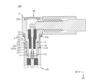
図1を参照すると、本開示の電気接続装置100の第1の実施形態は、レセプタクルコネクタ10と、レセプタクルコネクタ10と嵌合するために使用されるプラグコネクタ20とを含む。
Referring to FIG. 1, a first embodiment of an
以下の説明の便宜上、電気接続装置100において、第1の方向D1と、第1の方向D1に直交する第2の方向D2と、第1の方向D1及び第2の方向D2に直交する第3の方向D3が定義される。第1の実施形態では、第1の方向D1は、前後方向を例にとり、図1の矢印が指す方向が前方であり、前方と反対の方向が後方である。第2の方向D2は左右方向を例にとり、図1の矢印が指す方向は左であり、左と反対の方向は右であり、第3の方向D3は上下方向を例にとり、図1の矢印が指す方向は上であり、上と反対の方向は下である。
For the convenience of the following description, in the
図2、図3、及び図4を参照すると、レセプタクルコネクタ10は、外殻11、絶縁体12、及びメス端子13を含む。例えば、外殻11は、金属材料からできた導体である。外殻11には、位置決め溝110と、位置決め溝110の後端に連通するスルーホール111と、スルーホール111の後端に連通する挿入溝112と、挿入溝112の外周に連通し、挿入溝112の後端に隣接する内側環状溝113とが形成される。位置決め溝110は、絶縁体12をその中に収容するために使用される。挿入溝112及び内側環状溝113は、プラグコネクタ20をその中に挿入するために使用される。
2, 3, and 4, the
外殻11は、複数の接続ブロック114、嵌合端面115、後方内側円錐面116、内側環状面117、及び前方内側円錐面118を有する。複数の接続ブロック114は、前方に向いており、例えば、溶接によって回路基板(図示せず)に溶接することができる。嵌合端面115は、環状形状の形態であり、後方に向いており、複数の接続ブロック114に対向している。嵌合端面115は、第1の方向D1に沿って内側環状溝113から一定の距離だけ離間しており、プラグコネクタ20をそこに当接させるために使用される。後方内側円錐面116は、嵌合端面115の内縁から前方内側に斜めに延在する。内側環状面117は、後方内側円錐面116の前縁から前方に延在する。前方内側円錐面118は、内側環状面117の前縁から前方外側に斜めに延在し、内側環状溝113を取り囲む。
The
絶縁体12は、外殻11の位置決め溝110内に設けられる。メス端子13は、絶縁体12及び外殻11のスルーホール111内に設けられ、挿入溝112に部分的に延在する。
The
プラグコネクタ20は、導電体2、外部導体3、絶縁体4、中心端子5、カバー6、ケーブル7、及びブッシング8を含む。導電体2及び外部導体3は、例えば、金属材料からできた導体である。外部導体3は、後端31、少なくとも1つの前方ラッチ部分32、及び少なくとも1つの弾性片33を有する。後端31は、導電体2を電気的に接続する。前方ラッチ部分32は、後端31と対向し、後端31の前方に位置する。弾性片33は、後端31と前方ラッチ部分32との間に位置し、前方ラッチ部分32を接続する。導電体2及び外部導体3の少なくとも1つには係止面が形成され、係止面の位置は外部導体3の弾性片33に対応し、前方ラッチ部分32に近接している。係止面は、プラグコネクタ20がレセプタクルコネクタ10に挿入される深さを制限するように、レセプタクルコネクタ10の嵌合端面115を係止させるために使用される。
The
第1の実施形態では、プラグコネクタ20は、ライトアングルコネクタである。導電体2は、第1の導電部材21及び第2の導電部材22を有する。第1の導電部材21は、外部ケーシング210、環状周囲壁211、及びガイドポスト212を有する。外部ケーシング210は、中空の四角殻形状の形態であり、外部ケーシング210の内部は、後方に向かう後方係止面213を有する。環状周囲壁211は、外部ケーシング210の前端から前方に延在し、前端面214を有し、前端面214は、嵌合端面115に当接するために使用される係止面215を形成する。ガイドポスト212は、中空円筒形状の形態であり、外部ケーシング210の下端から下方に延在する。第2の導電部材22は、環状バレル形状の形態であり、第1の導電部材21の外部ケーシング210に後方から前方に組み立てられ、第2の導電部材22は、外部ケーシング210及び環状周囲壁211内に設けられ、前端面214から部分的に突出する。第2の導電部材22は、前方に向いており、かつ後方係止面213から離間しており、かつ後方係止面213の後方に位置する環状面221を有する。第1の導電部材21及び第2の導電部材22は、前方に開口する環状チャネル216を一緒に画定する。
In the first embodiment, the
第1の実施形態では、外部導体3は、打ち抜き加工により形成される環状のコンポーネントである。外部導体3は、複数の前方ラッチ部分32、複数の弾性片33、及び外側フランジ34を有する。複数の前方ラッチ部分32は、環状に配置されており、複数の弾性片33は、環状に配置されている。各前方ラッチ部分32は、対応する弾性片33の前端に接続され、かつレセプタクルコネクタ10の内側環状溝113にラッチするために使用される突起である。各前方ラッチ部分32は、前方内側円錐面118にラッチするために使用される円弧面321を有する。外側フランジ34は、後端31に接続されている。外部導体3には、複数のスリット35が形成され、各スリット35は、2つの対応する隣接する前方ラッチ部分32から後端31に近接するように延在し、各スリット35は、2つの対応する隣接する前方ラッチ部分32の間及び2つの対応する隣接する弾性片33の間に位置する。各スリット35は、2つの対応する隣接する前方ラッチ部分32の間に位置する開口部分351と、開口部分351に対向して後端31に近接する閉鎖部分352とを有する。
In the first embodiment, the
外部導体3は、第1の導電部材21の外部ケーシング210に後方から前方に組み立てられ、外部導体3は、外部ケーシング210及び環状周囲壁211内に設けられ、前端面214から部分的に突出する。外部導体3の後端31、複数の弾性片33、及び外側フランジ34は、環状チャネル216内に収容される。外側フランジ34は、第1の導電部材21の後方係止面213と第2の導電部材22の環状面221とによってクランプされる。複数の前方ラッチ部分32は、環状チャネル216から露出し、第1の導電部材21の前端面214から突出している。
The
絶縁体4は、導電体2の第2の導電部材22内に設けられる。中心端子5は、絶縁体4に設けられるオス端子である。中心端子5は、絶縁体4の前端及び後端から突出し、レセプタクルコネクタ10のメス端子13に電気的に接続されるために使用される。カバー6は、第1の導電部材21の外部ケーシング210内に組み立てられ、外部ケーシング210の後端を閉じる。ケーブル7は、外部ケーシング210及び第1の導電部材21のガイドポスト212内に設けられ、中心端子5に電気的に接続される。ブッシング8は、第1の導電部材21のガイドポスト212を覆い、ケーブル7とガイドポスト212との間の接続位置を覆うために使用される。
The
外部導体3の外側フランジ34が第1の導電部材21の後方係止面213と第2の導電部材22の環状面221とによってクランプされることにより、外側フランジ34は、外側フランジ34と第1の導電部材21との間に生じる間隙、又は外側フランジ34と第2の導電部材22との間に生じる間隙を回避するために、第1の導電部材21と第2の導電部材22との間にしっかりと固定され得、外側フランジ34、第1の導電部材21、及び第2の導電部材22の間の接触状態が保持される。したがって、電力の瞬断又は発生している信号の中断を回避するために、外部導体3及び導電体2を介した電流又は信号の伝達の安定性を確保することができる。更に、外部導体3の複数の前方ラッチ部分32のみが、環状チャネル216から露出し、外部導体3の残りの全ての位置が、環状チャネル216内に収容されることにより、導電体2の第2の導電部材22及び第1の導電部材21は、複数の弾性片33をそれぞれ複数の弾性片33の内側及び複数の弾性片33の外側から保護するように機能し得る。このため、複数の弾性片33が人的要因の影響により破損することを防止することができる。
By clamping the
図2及び図5を参照すると、プラグコネクタ20がレセプタクルコネクタ10と嵌合するとき、前方端面214から突出するプラグコネクタ20の第2の導電部材22の一部と、外部導体3の複数の前方ラッチ部分32は、それぞれ、レセプタクルコネクタ10の挿入溝112及び後方内側円錐面116と整列される。次に、プラグコネクタ20を、第1の方向D1に沿ってレセプタクルコネクタ10に向けて移動させる。プラグコネクタ20が移動する過程において、前端面214から突出する第2の導電部材22の一部は、最初に挿入溝112に挿入される。その後、各前方ラッチ部分32の円弧面321が後方内側円錐面116に接触し、後方内側円錐面116によって遮られる。後方内側円錐面116によって円弧面321に加えられる作用力は、前方ラッチ部分32を付勢して、前方ラッチ部分32に接続された対応する弾性片33を第2の導電部材22に向かって変位させて柔軟に変形させ、弾性復元力を蓄積し、複数の前方ラッチ部分32の複数の円弧面321が後方内側円錐面116に沿って前方に移動することができるようにする。これと同時に、中心端子5は、メス端子13に挿入され、メス端子13と電気的に接続される。次に、複数の円弧面321は、後方内側円錐面116から離れ、内側環状面117に接触する。
2 and 5, when the
複数の円弧面321が内側環状面117から離れて、内側環状溝113に移動するとき、各弾性片33によって蓄積された弾性復元力は、弾性片33に接続された対応する前方ラッチ部分32を復元させ、各前方ラッチ部分32が自動的に内側環状溝113にラッチし、円弧面321によって前方内側円錐面118にラッチすることができるようにする。各前方ラッチ部分32の円弧面321が前方内側円錐面118にラッチすると、係止面215を付勢して嵌合端面115にしっかりと当接させるために、円弧面321は、第1の方向D1に平行で後方に向かう推力Tを前方内側円錐面118に適用する。したがって、係止面215と嵌合端面115との間に間隙が生じることを回避することができ、したがって、プラグコネクタ20は、レセプタクルコネクタ10としっかりと嵌合することができ、レセプタクルコネクタ10に対して揺れることはなく、その結果、電流又は信号を伝達する際の安定性を促進することができる。
When the multiple
プラグコネクタ20をレセプタクルコネクタ10から引き抜くとき、プラグコネクタ20を後方に引き抜くために第1の方向D1に沿って力が適用される。各前方ラッチ部分32の円弧面321が、前方内側円錐面118によって遮られるため、前方内側円錐面118によって円弧面321に加えられる作用力は、前方ラッチ部分32を付勢して、前方ラッチ部分32に接続された対応する弾性片33を第2の導電部材22に向かって変位させて柔軟に変形させ、弾性復元力を蓄積し、したがって、複数の前方ラッチ部分32の複数の円弧面321が前方内側円錐面118に沿って後方に移動することができる。複数の円弧面321が逐次的に前方内側円錐面118及び内側環状面117から離れると、各弾性片33によって蓄積された弾性復元力が、弾性片33に接続された対応する前方ラッチ部分32を復元させ、各前方ラッチ部分32が図2に示される初期位置に自動的に復元するようにする。
When the
図1及び図3を参照すると、外部導体3の各スリット35が、2つの対応する隣接する前方ラッチ部分32から後端31に近接するように延在することによって、各弾性片33は、外部導体3の軸方向に一定の長さを占めることができる。したがって、電力の瞬断又は発生している信号の中断を回避するために、電流又は信号を伝達する際の安定性を促進することができるように、各弾性片33は、より良好な弾性を有し、繰り返される挿入及び引き抜きに耐え、変形しにくい。
1 and 3, each slit 35 of the
図1、図2、及び図5を参照すると、外側フランジ34が第1の導電部材21及び第2の導電部材22によってクランプされることによって、外側フランジ34と第1の導電部材21との間に生じる間隙、又は外側フランジ34と第2の導電部材22との間に生じる間隙を回避することができる。プラグコネクタ20がレセプタクルコネクタ10と嵌合するとき、係止面215が嵌合端面115にしっかりと当接することによって、係止面215と嵌合端面115との間に生じる間隙を回避することができる。外部導体3の各スリット35が、2つの対応する隣接する前方ラッチ部分32から後端31に近接するように延在することにより、各弾性片33は、より良好な弾性を有し、繰り返しの引き抜きに耐え、変形しにくい。上記のような構造設計によって、振動下で生じる電気接続装置100の電力の瞬断又は信号の中断を回避することができるため、プラグコネクタ20は、電流を印加して伝達を行う必要がある環境、例えば、音源機器又は自動車バックミラー疲労検出などに適用することができる。
1, 2, and 5, the
外部導体3の複数の前方ラッチ部分32の位置が、既存のマイクロミニチュア同軸コネクタのC字型ラッチリングの位置と同じであることによって、MMCX仕様に準拠するレセプタクルコネクタ10が、プラグコネクタ20に適合するようにその構造を変更する必要がないという前提で、レセプタクルコネクタ10は、プラグコネクタ20との嵌合を提供することができる。したがって、レセプタクルコネクタ10の構造をプラグコネクタ20に合わせて再設計する必要がないため、電気接続装置100全体の製造コストを下げることができる。
The positions of the multiple
第1の実施形態のプラグコネクタ20はまた、前方ラッチ部分32、弾性片33、及びスリット35の数をそれぞれ1つに設定してもよく、第1の実施形態により開示された数に限定されないことに留意されたい。第1の実施形態のレセプタクルコネクタ10の変形実装形態では、後方内側円錐面116及び前方内側円錐面118が互いに直接接続されるように、内側環状面117も除去され得る。第1の実施形態のレセプタクルコネクタ10の別の変形実装形態では、内側環状面117が嵌合端面115に直接接続されるように、後方内側円錐面116も除去され得る。
It should be noted that the
図6を参照すると、本開示の電気接続装置100の第2の実施形態は、全体構造において第1の実施形態と実質的に同じであり、それらの間の違いは、プラグコネクタ20にある。
Referring to FIG. 6, the second embodiment of the
レセプタクルコネクタ10の外殻11は、前方内側円錐面118の前方に位置し、かつ前方内側円錐面118から離間され、かつ内側環状溝113を取り囲む前方係止面119を更に有する。外部導体3の各前方ラッチ部分32は、円弧面321の前端に接続された前方当接面322を更に有し、前方当接面322は、前方係止面119に当接するために使用される。プラグコネクタ20がレセプタクルコネクタ10と嵌合するとき、係止面215及び前方当接面322は、それぞれ嵌合端面115及び前方係止面119にしっかりと当接する。このため、プラグコネクタ20とレセプタクルコネクタ10との嵌合の確実性を更に促進することができる。
The
図7、図8、及び図9を参照すると、本開示の電気接続装置100の第3の実施形態は、全体構造において第1の実施形態と実質的に同じであり、それらの間の違いは、プラグコネクタ20にある。
Referring to Figures 7, 8, and 9, the third embodiment of the
プラグコネクタ20は、ストレートコネクタである。導電体2の第1の導電部材21の外部ケーシング210は、スリーブ形状であり、外部ケーシング210の後端は開口形状の形態である。環状周囲壁211は、外部ケーシング210の前端から前方に延在する。導電体2は、中空円筒形状の第3の導電部材23を更に有する。第3の導電部材23は、第1の導電部材21の外部ケーシング210内に設けられ、第2の導電部材22の後方に位置し、外部ケーシング210の後端から部分的に突出する。ケーブル7は、第3の導電部材23及び絶縁体4内に設けられ、中心端子5に電気的に接続される。ブッシング8は、第3の導電部材23を覆う。第3の実施形態は、プラグコネクタ20の別の異なる形態を提供し、プラグコネクタ20は、第1の実施形態のプラグコネクタ20のものと同様の効果を同様に有する。
The
図10、図11、及び図12を参照すると、本開示の電気接続装置100の第4の実施形態は、全体構造において第1の実施形態と実質的に同じであり、それらの間の違いは、プラグコネクタ20にある。
Referring to Figures 10, 11, and 12, the fourth embodiment of the
導電体2は、構造が第1の実施形態の第1の導電部材21と同様である一体型コンポーネントである。導電体2は、外部ケーシング210、ガイドポスト212、及び環状円周方向壁217を有する。環状円周方向壁217は、外部ケーシング210の前端から前方に延在する。環状円周方向壁217は、外部ケーシング210に隣接して外側に開口する環状凹溝218を形成するように半径方向に凹んでいる。
The
外部導体3は、導電体2の環状円周方向壁217を覆い、貫通間隙36が形成されている。貫通間隙36は、対応する2つの隣接する前方ラッチ部分32から後端31まで延在する。貫通間隙36は、2つのスルー開口部361を有し、2つのスルー開口部361は、それぞれ、2つの対応する隣接する前方ラッチ部分32の間及び後端31に位置する。したがって、外部導体3が環状円周方向壁217を締め付けることができる締め付け弾性力を有するように、外部導体3の軸方向に直交する方向をとる外部導体3の断面はC字型の形態である。外部導体3は、後端31に接続された内側フランジ37を更に有する。内側フランジ37は、環状凹溝218にスナップ嵌めされ、内側フランジ37は、弾性力を印加して、締め付け弾性力によって導電体2の環状円周方向壁217をクランプする。
The
外部導体3の各弾性片33は、肩部331を有する。肩部331は、前方に向かう肩部面332を有し、肩部面332は、嵌合端面115の係止面333に当接するために使用されるように形成される。したがって、各弾性片33には係止面333が形成される。プラグコネクタ20がレセプタクルコネクタ10と嵌合するとき、係止面333は嵌合端面115にしっかりと当接する。
Each
内側フランジ37が環状円周方向壁217をクランプするように弾性力を印加することにより、内側フランジ37と環状円周方向壁217との間の接触状態が保持され、外部導体3が、第2の方向D2及び第3の方向D3で構成される二次元平面において環状円周方向壁217に対して任意に振れることを防止することができる。内側フランジ37が環状凹溝218にスナップ嵌めされることにより、外部導体3が、第1の方向D1に沿って環状円周方向壁217に対して任意に移動することを防止することができる。したがって、外部導体3と環状円周方向壁217との間に間隙が生じることを回避することができ、外部導体3及び導電体2を介した電流又は信号の伝達の安定性を確保することができ、電力の瞬断又は信号の中断の発生も回避することができる。
By applying an elastic force so that the
導電体2が一体型コンポーネントであることにより、プラグコネクタ20の構成コンポーネントの数を減らすことができる。したがって、導電体2と他の構成コンポーネントとの間の組み立ての利便性を促進することができ、プラグコネクタ20が組み立てられた後のプラグコネクタ20の構造は単純であり、プラグコネクタ20の製造コストを更に下げることができる。
Since the
図13、図14、及び図15を参照すると、本開示の電気接続装置100の第5の実施形態は、全体構造において第1及び第4の実施形態と実質的に同じであり、それらの間の違いは、プラグコネクタ20にある。
Referring to Figures 13, 14, and 15, the fifth embodiment of the
外部導体3の後端31は、第1の導電部材21の外部ケーシング210の前端に一体的に接続され、外部導体3及び第1の導電部材21は、一体的に形成され、一体型コンポーネントを一緒に構成する。後端31が外部ケーシング210の前端に一体的に接続されることにより、外部導体3と第1の導電部材21との間に間隙が生じない。外部導体3の各弾性片33は、構造において第4の実施形態と同様であり、各弾性片33は同様に肩部331を有し、肩部331は肩部面332を有し、肩部面332は、嵌合端面115の係止面333に当接するために使用されるように形成される。第2の導電部材22は、第1の導電部材21及び外部導体3の外部ケーシング210内に設けられ、複数の前方ラッチ部分32の前端から部分的に突出し、第2の導電部材22の環状面221は、第1の導電部材21の後方係止面213に当接する。
The
外部導体3及び第1の導電部材21が一体的に形成され、一体型コンポーネントを一緒に構成することにより、プラグコネクタ20の構成コンポーネントの数を減らすことができる。したがって、導電体2と他の構成コンポーネントとの間の組み立ての利便性を促進することができ、プラグコネクタ20が組み立てられた後のプラグコネクタ20の構造は単純であり、プラグコネクタ20の製造コストを更に下げることができる。
The
図16及び図17を参照すると、本開示の電気接続装置100の第6の実施形態は、全体構造において第5の実施形態と実質的に同じであり、それらの間の違いは、プラグコネクタ20にある。
Referring to Figures 16 and 17, the sixth embodiment of the
導電体2は、一体型コンポーネントであり、構造が第5の実施形態の第1の導電部材21と同じである。外部導体3の後端31は、導電体2の外部ケーシング210の前端に一体的に接続され、外部導体3及び導電体2は、一体的に形成され、一体型コンポーネントを一緒に構成する。絶縁体4は、構造が第5の実施形態の第2の導電部材22と同じである。絶縁体4は、提供セグメント41と、提供セグメント41の前端に形成されたヘッドセグメント42とを有する。絶縁体4の提供セグメント41は、導電体2及び外部導体3の外部ケーシング210内に設けられる。ヘッドセグメント42は、複数の前方ラッチ部分32の前端から突出し、挿入溝112に挿入するために使用される。提供セグメント41は、導電体2の後方係止面213に当接する環状面411を有する。ヘッドセグメント42が中心端子5の外周を取り囲むことにより、ユーザがプラグコネクタ20を斜めに不適切に挿入又は引き抜くときに、レセプタクルコネクタ10のメス端子13が中心端子5以外の導体に接触して短絡を引き起こすことを回避することができる。
The
導電体2が一体型コンポーネントであり、外部導体3及び導電体2が一体的に形成されて一体型コンポーネントを一緒に構成することにより、プラグコネクタ20の構成コンポーネントの数を更に減らすことができる。したがって、導電体2と他の構成コンポーネントとの間の組み立ての利便性を促進することができ、プラグコネクタ20が組み立てられた後のプラグコネクタ20の構造は単純であり、プラグコネクタ20の製造コストを更に下げることができる。
The
図18、図19、及び図20を参照すると、本開示の電気接続装置100の第7の実施形態は、全体構造において第1及び第4の実施形態と実質的に同じであり、それらの間の違いは、プラグコネクタ20にある。
Referring to Figures 18, 19, and 20, the seventh embodiment of the
導電体2は、一体型コンポーネントであり、構造が第4の実施形態の導電体2と同様である。導電体2は、外部ケーシング210、環状周囲壁211、ガイドポスト212、及び環状円周方向壁217を有する。環状周囲壁211は、環状円周方向壁217を取り囲む。環状円周方向壁217は、環状周囲壁211の前端面214から部分的に突出する。外部ケーシング210、環状周囲壁211、及び環状円周方向壁217は、環状チャネル216を一緒に画定する。
The
外部導体3は、構造が第4の実施形態の外部導体3と同様である。外部導体3は、導電体2の環状円周方向壁217を覆っている。外部導体3の後端31及び複数の弾性片33は、環状チャネル216内に収容され、複数の前方ラッチ部分32は、環状チャネル216から露出される。後端31に隣接する外部導体3の位置は、締め付け弾性力により弾性力を印加することによって導電体2の環状円周方向壁217をクランプする。各弾性片33は、対応する前方ラッチ部分32に接続された第1の弾性片本体334と、第1の弾性片本体334から後方に延在する第2の弾性片本体335とを有する。第2の弾性片本体335は、導電体2の環状円周方向壁217に当接するように弾性力を印加するために使用される。複数の弾性片33は、複数の第2の弾性片本体335がそれぞれ弾性力を印加することにより、環状円周方向壁217をクランプする。したがって、外部導体3と環状円周方向壁217との接触状態が保持され、第2の方向D2及び第3の方向D3で構成される二次元平面において、外部導体3が、環状円周方向壁217に対して任意に揺れることを防止することができ、外部導体3が、環状円周方向壁217に対して第1の方向D1に沿って任意に移動することを更に防止することができる。したがって、外部導体3と環状円周方向壁217との間に間隙が生じることを回避することができ、外部導体3及び導電体2を介した電流又は信号の伝達の安定性を確保することができ、電力の瞬断又は信号の中断の発生も回避することができる。
The
外部導体3の複数の前方ラッチ部分32のみが、環状チャネル216から露出し、外部導体3の残りの全ての位置が、環状チャネル216内に収容されることにより、導電体2の環状円周方向壁217及び環状周囲壁211は、複数の弾性片33をそれぞれ複数の弾性片33の内側及び複数の弾性片33の外側から保護するように機能し得る。このため、複数の弾性片33が人的要因の影響により破損することを防止することができる。
Only the multiple
図21、図22、及び図23を参照すると、本開示の電気接続装置100の第8の実施形態は、全体構造において第1、第4、及び第7の実施形態と実質的に同じであり、それらの間の違いは、プラグコネクタ20にある。
Referring to Figures 21, 22, and 23, the eighth embodiment of the
導電体2は、一体型コンポーネントであり、構造が第7の実施形態の導電体2と同様である。外部導体3は、構造が第4の実施形態の外部導体3と同様であるが、違いは、第8の実施形態の外部導体3が貫通間隙36及び内側フランジ37を有していない点である。外部導体3が導電体2に組み立てられるとき、最初に、外部導体3が導電体2の環状円周方向壁217を覆い、その結果、後端31及び外側フランジ34が環状チャネル216内に収容される。その後、環状周囲壁211にローリングリベットなどの加工操作を行い、それによって環状周囲壁211が環状ラッチ押圧壁211’を形成する。環状ラッチ押圧壁211’の前端は、内側に曲がるように変形され、外側フランジ34を係止して押圧するため、外側フランジ34が、環状チャネル216から外れることを防止することができ、後端31及び外側フランジ34は、環状チャネル216内にしっかりと固定することができ、外部導体3と導電体2との間に間隙が生じることを回避する。したがって、外部導体3及び導電体2を介した電流又は信号の伝達の安定性を確保することができ、電力の瞬断又は信号の中断の発生も回避することができる。
The
図24、図25、及び図26を参照すると、本開示の電気接続装置100の第9の実施形態は、全体構造において第5の実施形態と実質的に同じであり、それらの間の違いは、プラグコネクタ20にある。
Referring to Figures 24, 25, and 26, the ninth embodiment of the
絶縁体4は、中空円筒形状の形態であり、提供セグメント41と、提供セグメント41の前端に形成されたヘッドセグメント42とを有する。絶縁体4の提供セグメント41は、第2の導電部材22に設けられる。ヘッドセグメント42は、第2の導電部材22の前端から突出し、挿入溝112に挿入するために使用される。ヘッドセグメント42が中心端子5の外周を取り囲むことにより、ユーザがプラグコネクタ20を斜めに不適切に挿入又は引き抜くときに、レセプタクルコネクタ10のメス端子13が中心端子5以外の導体に接触して短絡を引き起こすことを回避することができる。
The
図27及び図28を参照すると、本開示の電気接続装置100の第10の実施形態は、全体構造において第5の実施形態と実質的に同じであり、それらの間の違いは、プラグコネクタ20にある。
Referring to Figures 27 and 28, the tenth embodiment of the
第1の導電部材21の外部ケーシング210は、内側干渉円周方向壁219を有する。第2の導電部材22は、第1の導電部材21の外部ケーシング210内に前方から後方に組み立てられ、内側干渉円周方向壁219と干渉する。第2の導電部材22は、第1の導電部材21及び外部導体3の外部ケーシング210内に設けられ、複数の前方ラッチ部分32の前端から部分的に突出する。
The
図29及び図30を参照すると、本開示の電気接続装置100の第11の実施形態は、全体構造において第1の実施形態と実質的に同じであり、それらの間の違いは、プラグコネクタ20にある。
29 and 30, the eleventh embodiment of the
第1の導電部材21の外部ケーシング210は、内側干渉円周方向壁219を有する。第2の導電部材22は、第1の導電部材21の外部ケーシング210内に前方から後方に組み立てられ、内側干渉円周方向壁219と干渉する。第2の導電部材22は、第1の導電部材21の外部ケーシング210及び環状周囲壁211内に設けられ、前端面214から部分的に突出する。第2の導電部材22は、外側に開口して内側干渉円周方向壁219に隣接する環状凹溝222を形成するように半径方向に凹んでいる。第1の導電部材21及び第2の導電部材22は、前方に開口して環状凹溝222に連通する環状チャネル216を一緒に画定する。
The
外部導体3は、第2の導電部材22を覆い、貫通間隙36が形成される。後端31及び複数の弾性片33は環状チャネル216に収容され、複数の前方ラッチ部32は環状チャネル216から露出される。外部導体3は、後端31に接続された内側フランジ37を更に有し、内側フランジ37は、環状凹溝222にスナップ嵌めされ、内側フランジ37は、弾性力を印加して、締め付け弾性力によって第2の導電部材22をクランプする。
The
図31及び図32を参照すると、本開示の電気接続装置100の第12の実施形態は、全体構造において第11の実施形態と実質的に同じであり、それらの間の違いは、プラグコネクタ20にある。
Referring to Figures 31 and 32, the twelfth embodiment of the
外部導体3の各弾性片33は、構造が第4の実施形態と同様であり、各弾性片33は肩部331を同様に有し、肩部331は肩部面332を有する。前端面214の肩部面332及び導電体2は、嵌合端面115に当接するために使用される係止面220を一緒に形成する。したがって、プラグコネクタ20がレセプタクルコネクタ10と嵌合するとき、導電体2及び外部導体3は、それぞれ前端面214及び肩部面332によって嵌合端面115にしっかりと当接することができる。
Each
第3の実施形態から第12の実施形態のそれぞれの別の実装において、各前方ラッチ部分32は、構造において第2の実施形態と同じであり、プラグコネクタ20がレセプタクルコネクタ10と嵌合する堅固さを更に促進するように、前方係止面119に当接するために使用される前方当接面322を同様に有することに留意されたい。
Note that in each of the alternative implementations of the third through twelfth embodiments, each
結論として、電気接続装置100の各実施形態では、外部導体3と導電体2との間に間隙が生じず、係止面215、333、220と嵌合端面115との間に間隙が生じず、各弾性片33がより良好な弾性を有し、繰り返しの挿入及び引き抜きに耐え、変形しにくく、電流又は信号の伝達の安定性を確保することができ、電力の瞬断又は信号の中断の発生も回避することができるため、実際に本開示の目的を達成することができる。
In conclusion, in each embodiment of the
しかしながら、上記の説明は本開示の実施形態のためのものにすぎず、本開示の実施範囲を限定することを意図するものではなく、特許請求の範囲及び明細書の内容に従ってなされた単純な均等の変更及び修正は、依然として本開示の範囲に含まれる。 However, the above description is merely for the embodiment of the present disclosure and is not intended to limit the scope of the present disclosure, and simple equivalent changes and modifications made in accordance with the claims and the contents of the specification still fall within the scope of the present disclosure.
Claims (20)
該プラグコネクタは、
導電体と、
後端、少なくとも1つの前方ラッチ部分、及び少なくとも1つの弾性片を有する外部導体であって、前記後端が導電体と電気的に接続しており、前記前方ラッチ部分が後端と対向して該後端の前方に位置しており、前記弾性片が後端と前方ラッチ部分との間に位置して該前方ラッチ部分と接続しており、前記導電体及び外部導体の少なくとも一方には係止面が形成されており、該係止面の位置が前記外部導体の弾性片に対応し、前方ラッチ部分に近接している、外部導体と、
前記導電体内に設けられた絶縁体と、
該絶縁体に提供された中心端子と、を含む、電気接続装置。 An electrical connection device, the electrical connection device including a plug connector;
The plug connector comprises:
A conductor;
an outer conductor having a rear end, at least one front latch portion, and at least one elastic piece, the rear end being electrically connected to a conductor, the front latch portion being opposite the rear end and located forward of the rear end, the elastic piece being located between the rear end and the front latch portion and connected to the front latch portion, a locking surface being formed on at least one of the conductor and the outer conductor, the position of the locking surface corresponding to the elastic piece of the outer conductor and being adjacent to the front latch portion;
an insulator provided within the conductor;
and a central terminal provided on the insulator.
前記導電体が、前方に延在して前記弾性片を取り囲む環状周囲壁を有し、該環環状周囲壁が前端面を有し、
前記肩部面及び前端面が、前記係止面を一緒に形成する、請求項1に記載の電気接続装置。 The elastic piece has a shoulder, the shoulder having a shoulder surface,
The conductor has an annular peripheral wall extending forward and surrounding the elastic piece, the annular peripheral wall having a front end surface;
The electrical connection device of claim 1 , wherein said shoulder surface and front end surface together form said locking surface.
前記外部導体が導電体を覆い、前記外部導体には貫通間隙が形成され、該貫通間隙が前方ラッチ部分から後端まで延在し、前記外部導体が後端に接続された内側フランジを有し、該内側フランジが、環状凹溝にスナップ嵌めされ、弾性力を印加して導電体をクランプする、請求項1に記載の電気接続装置。 The conductor is an integral component, the conductor has an annular groove formed therein and opening outward;
2. The electrical connection device of claim 1, wherein the outer conductor covers the conductor, the outer conductor has a through gap formed therein, the through gap extending from a front latch portion to a rear end, the outer conductor has an inner flange connected to the rear end, the inner flange snap-fitting into an annular groove and applying a resilient force to clamp the conductor.
前記外部導体及び導電体が、一体的に形成されて一体型コンポーネントを一緒に構成し、
前記絶縁体が、前記導電体及び外部導体に提供された提供セグメントと、該提供セグメントの前端に形成され、前記前方ラッチ部分の前端から突出するヘッドセグメントと、を有する、請求項1に記載の電気接続装置。 the electrical conductor is an integral component, and a rear end of the outer conductor is integrally connected to the electrical conductor;
the outer conductor and the electrical conductor are integrally formed to together define an integral component;
2. The electrical connection device of claim 1, wherein the insulator has a presentation segment presented to the conductor and outer conductor, and a head segment formed at a front end of the presentation segment and projecting from a front end of the front latch portion.
前記外部導体には前方ラッチ部分から後端まで延在する貫通間隙が形成され、前記外部導体が、導電体を覆い、弾性力を印加して導電体をクランプし、前記後端及び弾性片が環状チャネル内に収容され、前記前方ラッチ部分が環状チャネルから露出する、請求項1に記載の電気接続装置。 the electrical conductor is a unitary component, the electrical conductor having a forwardly opening annular channel formed therein;
2. The electrical connection device of claim 1, wherein the outer conductor has a through gap extending from the front latch portion to the rear end, the outer conductor covers the conductor and applies an elastic force to clamp the conductor, the rear end and the elastic piece are received within the annular channel, and the front latch portion is exposed from the annular channel.
前記貫通間隙が対応する2つの隣接する前方ラッチ部分から後端まで延在し、
各スリットが、対応する2つの隣接する前方ラッチ部分から後端に近接するように延在し、各スリットが、対応する2つの隣接する前方ラッチ部分の間及び2つの対応する隣接する弾性片の間に位置し、各弾性片が、対応する前方ラッチ部分に接続された第1の弾性片本体と、該第1の弾性片本体から後方に延在して導電体に当接する弾性力を印加する第2の弾性片本体と、を有する、請求項12に記載の電気接続装置。 The outer conductor has a plurality of front latch portions and a plurality of elastic pieces, and a plurality of slits are formed in the outer conductor;
the through gaps extend from corresponding two adjacent forward latch portions to a rear end;
13. The electrical connection device of claim 12, wherein each slit extends from two corresponding adjacent front latch portions proximate to the rear end, each slit is located between two corresponding adjacent front latch portions and between two corresponding adjacent elastic pieces, and each elastic piece has a first elastic piece body connected to the corresponding front latch portion and a second elastic piece body extending rearward from the first elastic piece body to apply an elastic force to abut against the conductor.
前記外部導体が後端に接続された外側フランジを更に有し、前記外部導体が導電体を覆い、後端及び外側フランジが環状チャネル内に収容され、
前記導電体が、前方に延在して環状チャネルを取り囲む環状ラッチ押圧壁を有し、
該環状ラッチ押圧壁の前端が、内側に曲がるように変形して外側フランジをラッチして押圧する、請求項1に記載の電気接続装置。 the electrical conductor is a unitary component, the electrical conductor having a forwardly opening annular channel formed therein;
the outer conductor further comprises an outer flange connected to a rear end, the outer conductor covering the conductor, the rear end and the outer flange being received within an annular channel;
the electrical conductor having an annular latch pressure wall extending forwardly and surrounding an annular channel;
2. The electrical connection device of claim 1, wherein a front end of said annular latch pressure wall is deformed to bend inwardly to latch and press against an outer flange.
前記外部導体が、後端に接続された外側フランジを更に有し、
前記後端、弾性片、及び外側フランジが、環状チャネル内に収容され、前方ラッチ部分が、環状チャネルから露出され、前記第1の導電部材の前端から突出し、前記外側フランジが、第1の導電部材及び第2の導電部材によってクランプされる、請求項1に記載の電気接続装置。 the electrical conductor having a first conductive member and a second conductive member disposed within the first conductive member and projecting partially from a front end of the first conductive member, the first conductive member and the second conductive member together defining a forwardly opening annular channel;
the outer conductor further having an outer flange connected to a rear end;
2. The electrical connection device of claim 1, wherein the rear end, resilient piece, and outer flange are received within an annular channel, a front latch portion is exposed from the annular channel and protrudes from a front end of the first conductive member, and the outer flange is clamped by the first conductive member and the second conductive member.
前記外部導体が、該外部導体の後端に接続された外側フランジを更に有し、
前記外部導体の後端、弾性片、及び外側フランジが、環状チャネル内に収容され、前記前方ラッチ部分が、環状チャネルから露出され、第1の導電部材の前端から突出し、前記外側フランジが、第1の導電部材及び第2の導電部材によってクランプされる、請求項1に記載の電気接続装置。 the electrical conductor comprises a first conductive member, a second conductive member disposed within the first conductive member and partially projecting from a front end of the first conductive member, and a third conductive member disposed within the first conductive member and partially projecting from a rear end of the first conductive member, the first conductive member and second conductive member together defining a forwardly opening annular channel;
the outer conductor further comprises an outer flange connected to a rear end of the outer conductor;
2. The electrical connection device of claim 1, wherein the rear end of the outer conductor, the resilient piece, and the outer flange are received within an annular channel, the forward latch portion is exposed from the annular channel and protrudes from a front end of the first conductive member, and the outer flange is clamped by the first conductive member and the second conductive member.
前記外部導体の後端が、前記第1の導電部材に一体的に接続され、前記外部導体及び第1の導電部材が、一体的に形成されて一体型コンポーネントを一緒に構成し、
前記第2の導電部材が、前記第1の導電部材及び外部導体内に設けられ、前方ラッチ部分の前端から部分的に突出する、請求項1に記載の電気接続装置。 the conductor has a first conductive member and a second conductive member;
a rear end of the outer conductor is integrally connected to the first conductive member, the outer conductor and the first conductive member being integrally formed together to define an integrated component;
2. The electrical connection apparatus of claim 1, wherein said second conductive member is disposed within said first conductive member and outer conductor and protrudes partially beyond a front end of the front latch portion.
前記外部導体の後端が、前記第1の導電部材に一体的に接続され、前記外部導体及び第1の導電部材が、一体的に形成されて一体型コンポーネントを構成し、
前記第2の導電部材が、前記第1の導電部材及び外部導体内に設けられ、前方ラッチ部分の前端から部分的に突出し、
前記絶縁体が、前記第2の導電部材に提供された提供セグメントと、該提供セグメントの前端に形成され、前記第2の導電部材の前端から突出するヘッドセグメントと、を有する、請求項1に記載の電気接続装置。 the conductor has a first conductive member and a second conductive member;
a rear end of the outer conductor is integrally connected to the first conductive member, the outer conductor and the first conductive member being integrally formed to form an integrated component;
the second conductive member is disposed within the first conductive member and the outer conductor and partially projects beyond a front end of the forward latch portion;
2. The electrical connection device of claim 1, wherein the insulator comprises a presentation segment provided on the second conductive member and a head segment formed at a front end of the presentation segment and projecting from the front end of the second conductive member.
前記外部導体の後端が、前記第1の導電部材に一体的に接続され、前記外部導体及び第1の導電部材が、一体的に形成されて一体型コンポーネントを構成し、
前記第2の導電部材が、前記第1の導電部材及び外部導体内に設けられ、前方ラッチ部分の前端から部分的に突出し、
前記第1の導電部材が、前記第2の導電部材と干渉する内側干渉円周方向壁を有する、請求項1に記載の電気接続装置。 the conductor has a first conductive member and a second conductive member;
a rear end of the outer conductor is integrally connected to the first conductive member, the outer conductor and the first conductive member being integrally formed to form an integrated component;
the second conductive member is disposed within the first conductive member and the outer conductor and partially projects beyond a front end of the forward latch portion;
2. The electrical connection apparatus of claim 1, wherein said first conductive member has an inner interference circumferential wall that interferes with said second conductive member.
前記外部導体は第2の導電部材を覆い、前記外部導体には貫通間隙が形成され、該貫通間隙が、前方ラッチ部分から後端に延在し、
前記外部導体が、後端に接続された内側フランジを更に有し、
前記後端、弾性片、及び内側フランジが、環状チャネル内に収容され、前記前方ラッチ部分が、環状チャネルから露出され、前記内側フランジが、環状凹溝にスナップ嵌めされ、弾性力を印加して第2の導電部材をクランプする、請求項1に記載の電気接続装置。 the electrical conductor comprises a first conductive member and a second conductive member disposed within the first conductive member and partially projecting from a front end of the first conductive member, the first conductive member having an inner interfering circumferential wall, the second conductive member interfering with the inner interfering circumferential wall, the second conductive member having an outwardly opening annular groove formed therein, the first conductive member and the second conductive member together defining an annular channel opening forwardly and communicating with the annular groove;
the outer conductor covers the second conductive member, the outer conductor has a through gap formed therein, the through gap extending from the forward latch portion to a rear end;
the outer conductor further having an inner flange connected to a rear end;
2. The electrical connection device of claim 1, wherein the rear end, the elastic piece, and the inner flange are received within an annular channel, the front latch portion is exposed from the annular channel, and the inner flange is snap-fitted into an annular recessed groove to apply an elastic force to clamp the second conductive member.
Applications Claiming Priority (2)
| Application Number | Priority Date | Filing Date | Title |
|---|---|---|---|
| CN202211471880.1A CN118117372A (en) | 2022-11-23 | 2022-11-23 | Electrical connection device |
| CN202211471880.1 | 2022-11-23 |
Publications (2)
| Publication Number | Publication Date |
|---|---|
| JP2024075558A true JP2024075558A (en) | 2024-06-04 |
| JP7792941B2 JP7792941B2 (en) | 2025-12-26 |
Family
ID=88965112
Family Applications (1)
| Application Number | Title | Priority Date | Filing Date |
|---|---|---|---|
| JP2023198271A Active JP7792941B2 (en) | 2022-11-23 | 2023-11-22 | Electrical Connection Device |
Country Status (4)
| Country | Link |
|---|---|
| US (1) | US20240170888A1 (en) |
| EP (1) | EP4376227A1 (en) |
| JP (1) | JP7792941B2 (en) |
| CN (1) | CN118117372A (en) |
Citations (6)
| Publication number | Priority date | Publication date | Assignee | Title |
|---|---|---|---|---|
| JPS59207574A (en) * | 1983-04-29 | 1984-11-24 | アンプ・インコ−ポレ−テツド | Coaxial connector |
| JP2001508231A (en) * | 1997-01-13 | 2001-06-19 | ザ ウィタカー コーポレーション | Coaxial switch connector assembly |
| US20140017928A1 (en) * | 2011-02-23 | 2014-01-16 | Molex Incorporated | Lockable mating connector |
| CN207504225U (en) * | 2017-11-30 | 2018-06-15 | 东莞市旭建电子科技有限公司 | The double elastic contact type MMCX radio frequency connectors of plug |
| US20190020149A1 (en) * | 2017-07-12 | 2019-01-17 | Commscope Technologies Llc | Quick-Locking Coaxial Connector |
| CN110611192A (en) * | 2019-09-16 | 2019-12-24 | 南京康尼科技实业有限公司 | Positioning claw for connector and electric connector |
Family Cites Families (3)
| Publication number | Priority date | Publication date | Assignee | Title |
|---|---|---|---|---|
| US7455550B1 (en) * | 2008-02-12 | 2008-11-25 | Tyco Electronics Corporation | Snap-on coaxial plug |
| CN106030912B (en) * | 2013-12-20 | 2019-03-12 | Ppc宽带公司 | RF Shields for Miniature Coax Connectors |
| CN209786238U (en) | 2019-04-09 | 2019-12-13 | 东莞市旭建电子科技有限公司 | Integrated elastic contact type MMCX radio frequency connector |
-
2022
- 2022-11-23 CN CN202211471880.1A patent/CN118117372A/en active Pending
-
2023
- 2023-11-22 US US18/517,004 patent/US20240170888A1/en active Pending
- 2023-11-22 JP JP2023198271A patent/JP7792941B2/en active Active
- 2023-11-23 EP EP23211736.6A patent/EP4376227A1/en active Pending
Patent Citations (6)
| Publication number | Priority date | Publication date | Assignee | Title |
|---|---|---|---|---|
| JPS59207574A (en) * | 1983-04-29 | 1984-11-24 | アンプ・インコ−ポレ−テツド | Coaxial connector |
| JP2001508231A (en) * | 1997-01-13 | 2001-06-19 | ザ ウィタカー コーポレーション | Coaxial switch connector assembly |
| US20140017928A1 (en) * | 2011-02-23 | 2014-01-16 | Molex Incorporated | Lockable mating connector |
| US20190020149A1 (en) * | 2017-07-12 | 2019-01-17 | Commscope Technologies Llc | Quick-Locking Coaxial Connector |
| CN207504225U (en) * | 2017-11-30 | 2018-06-15 | 东莞市旭建电子科技有限公司 | The double elastic contact type MMCX radio frequency connectors of plug |
| CN110611192A (en) * | 2019-09-16 | 2019-12-24 | 南京康尼科技实业有限公司 | Positioning claw for connector and electric connector |
Also Published As
| Publication number | Publication date |
|---|---|
| US20240170888A1 (en) | 2024-05-23 |
| EP4376227A1 (en) | 2024-05-29 |
| CN118117372A (en) | 2024-05-31 |
| JP7792941B2 (en) | 2025-12-26 |
Similar Documents
| Publication | Publication Date | Title |
|---|---|---|
| US10559919B2 (en) | Connector having elastically deformable pressing protrusions | |
| CN102957052B (en) | Shielded connector | |
| CN105027359B (en) | Coaxial cable connector with overall coherence contact portion | |
| US12525752B1 (en) | Plug connector and plug connector assembly | |
| EP2221927A2 (en) | Sealed and grounded electrical connector and sealed and grounded electrical connector assembly | |
| JP2019114489A (en) | connector | |
| KR20020061531A (en) | Right angle, snap on coaxial electrecal connector | |
| US10530094B2 (en) | Electrical connector | |
| US7064266B2 (en) | Shielded connector | |
| CN104124556A (en) | Electrical connector having resilient latches | |
| WO2019046517A1 (en) | Coaxial cable connector with grounding coupling nut | |
| US6033260A (en) | Shielding-member-containing connector assembly | |
| JP6847016B2 (en) | Coaxial cable connector | |
| CN118872162A (en) | Shielding unit | |
| US20250174942A1 (en) | Connector Core Assembly, Connector and Connector Assembly | |
| US20220190526A1 (en) | Connector | |
| US20220140539A1 (en) | Male Connector, Female Connector and Connector Assembly | |
| KR20230038585A (en) | Circular plug connector with shield connection | |
| JP2024075558A (en) | Electrical Connection Device | |
| JP2019087517A (en) | Electrical connector | |
| CN117438815A (en) | Shielded spring contacts, plug-in connectors and plug-in connector systems | |
| CN110212346A (en) | Connector and its housing | |
| TWI859636B (en) | Electrical connection device | |
| KR20210078321A (en) | Connector | |
| CN222940259U (en) | Waterproof end cap of seal and cable subassembly |
Legal Events
| Date | Code | Title | Description |
|---|---|---|---|
| A621 | Written request for application examination |
Free format text: JAPANESE INTERMEDIATE CODE: A621 Effective date: 20240321 |
|
| A131 | Notification of reasons for refusal |
Free format text: JAPANESE INTERMEDIATE CODE: A131 Effective date: 20241224 |
|
| A601 | Written request for extension of time |
Free format text: JAPANESE INTERMEDIATE CODE: A601 Effective date: 20250319 |
|
| A521 | Request for written amendment filed |
Free format text: JAPANESE INTERMEDIATE CODE: A523 Effective date: 20250327 |
|
| A131 | Notification of reasons for refusal |
Free format text: JAPANESE INTERMEDIATE CODE: A131 Effective date: 20250715 |
|
| A521 | Request for written amendment filed |
Free format text: JAPANESE INTERMEDIATE CODE: A523 Effective date: 20250919 |
|
| TRDD | Decision of grant or rejection written | ||
| A01 | Written decision to grant a patent or to grant a registration (utility model) |
Free format text: JAPANESE INTERMEDIATE CODE: A01 Effective date: 20251125 |
|
| A61 | First payment of annual fees (during grant procedure) |
Free format text: JAPANESE INTERMEDIATE CODE: A61 Effective date: 20251216 |
|
| R150 | Certificate of patent or registration of utility model |
Ref document number: 7792941 Country of ref document: JP Free format text: JAPANESE INTERMEDIATE CODE: R150 |