JP2015061725A - Process waste gas scrubber - Google Patents
Process waste gas scrubber Download PDFInfo
- Publication number
- JP2015061725A JP2015061725A JP2014192927A JP2014192927A JP2015061725A JP 2015061725 A JP2015061725 A JP 2015061725A JP 2014192927 A JP2014192927 A JP 2014192927A JP 2014192927 A JP2014192927 A JP 2014192927A JP 2015061725 A JP2015061725 A JP 2015061725A
- Authority
- JP
- Japan
- Prior art keywords
- waste gas
- process waste
- reaction
- cooling
- trap
- Prior art date
- Legal status (The legal status is an assumption and is not a legal conclusion. Google has not performed a legal analysis and makes no representation as to the accuracy of the status listed.)
- Granted
Links
Images


Classifications
-
- H—ELECTRICITY
- H10—SEMICONDUCTOR DEVICES; ELECTRIC SOLID-STATE DEVICES NOT OTHERWISE PROVIDED FOR
- H10P—GENERIC PROCESSES OR APPARATUS FOR THE MANUFACTURE OR TREATMENT OF DEVICES COVERED BY CLASS H10
- H10P95/00—Generic processes or apparatus for manufacture or treatments not covered by the other groups of this subclass
-
- B—PERFORMING OPERATIONS; TRANSPORTING
- B01—PHYSICAL OR CHEMICAL PROCESSES OR APPARATUS IN GENERAL
- B01D—SEPARATION
- B01D53/00—Separation of gases or vapours; Recovering vapours of volatile solvents from gases; Chemical or biological purification of waste gases, e.g. engine exhaust gases, smoke, fumes, flue gases, aerosols
- B01D53/34—Chemical or biological purification of waste gases
- B01D53/46—Removing components of defined structure
- B01D53/68—Halogens or halogen compounds
-
- B—PERFORMING OPERATIONS; TRANSPORTING
- B01—PHYSICAL OR CHEMICAL PROCESSES OR APPARATUS IN GENERAL
- B01J—CHEMICAL OR PHYSICAL PROCESSES, e.g. CATALYSIS OR COLLOID CHEMISTRY; THEIR RELEVANT APPARATUS
- B01J20/00—Solid sorbent compositions or filter aid compositions; Sorbents for chromatography; Processes for preparing, regenerating or reactivating thereof
Landscapes
- Chemical & Material Sciences (AREA)
- Engineering & Computer Science (AREA)
- Chemical Kinetics & Catalysis (AREA)
- Analytical Chemistry (AREA)
- Environmental & Geological Engineering (AREA)
- Biomedical Technology (AREA)
- General Chemical & Material Sciences (AREA)
- Oil, Petroleum & Natural Gas (AREA)
- Health & Medical Sciences (AREA)
- Organic Chemistry (AREA)
- Treating Waste Gases (AREA)
- Gas Separation By Absorption (AREA)
- Exhaust Gas Treatment By Means Of Catalyst (AREA)
- Solid-Sorbent Or Filter-Aiding Compositions (AREA)
- Catalysts (AREA)
- Physical Or Chemical Processes And Apparatus (AREA)
Abstract
Description
本発明は、工程廃ガス処理用スクラバに係り、より詳しくは、半導体製造工程、液晶ディスプレイ(Liquid Crystal Display:LCD)または有機エレクトロルミネッセンス照明(Organic Light Emitting Display:OLED)のような平板表示装置の製造工程または太陽電池製造工程または発光ダイオード(LED)製造工程などで排出される工程廃ガスを処理する工程廃ガス処理用スクラバに関する。 The present invention relates to a process waste gas treatment scrubber, and more particularly, to a flat panel display device such as a semiconductor manufacturing process, a liquid crystal display (LCD), or an organic electroluminescent illumination (OLED). The present invention relates to a process waste gas processing scrubber that processes process waste gas discharged in a manufacturing process, a solar cell manufacturing process, a light emitting diode (LED) manufacturing process, or the like.
半導体製造工程、LCDまたはOLEDのような平板表示装置の製造工程、太陽電池やLED製造工程のように特殊ガスを使用する工程では、人体と環境に有害な廃ガス(以下、「工程廃ガス」と称する)が発生する。
工程廃ガスによる環境汚染を防止するために、工程廃ガスは外部に放出される前に浄化処理されなければならない。
そのために、工程廃ガスは工程廃ガス処理用スクラバによって浄化された後、外部に排出される。
Waste gas harmful to human body and environment (hereinafter referred to as “process waste gas”) in the semiconductor manufacturing process, the manufacturing process of flat panel display devices such as LCD or OLED, and the process of using special gas such as solar cell and LED manufacturing process. Occurs).
In order to prevent environmental pollution due to process waste gas, the process waste gas must be purified before being released to the outside.
For this purpose, the process waste gas is purified by a process waste gas processing scrubber and then discharged to the outside.
一般的に、工程廃ガス処理用スクラバは、工程廃ガス内の有害物質を分解するかまたは化学反応を促進するために高温の熱源を提供する反応チャンバと、反応チャンバを通過した廃ガスから固体状のパウダーをフィルタリングするための水処理タワーで構成される。
一方、工程廃ガスは、パーフルオロケミカルズ(PFCs)、クロロフルオロカーボン(CFCs)がプラズマ処理される過程で発生するフッ化水素(HF)や塩化水素(HCl)等のハロゲン化水素化合物を多量に含む。
ハロゲン化水素化合物等の水溶性ガスは主に水中を通過させるか、水を噴射する湿式工程を通じて捕集して処理されるので、大量の廃水が発生し、その廃水を収集して処理しなければならない煩わしさがある。
また、湿式工程を用いる場合、ハロゲン化水素化合物を含む水溶性ガスの除去効率が低いことも問題である(例えば、特許文献1〜3参照)。
Generally, a process waste gas treatment scrubber is composed of a reaction chamber that provides a high temperature heat source for decomposing harmful substances in the process waste gas or promoting chemical reactions, and a solid from the waste gas that has passed through the reaction chamber. It consists of a water treatment tower for filtering the powder.
On the other hand, process waste gas contains a large amount of hydrogen halide compounds such as hydrogen fluoride (HF) and hydrogen chloride (HCl) generated in the process of plasma treatment of perfluorochemicals (PFCs) and chlorofluorocarbons (CFCs). .
Water-soluble gases such as hydrogen halide compounds are mainly collected and processed through a wet process that allows water to pass through or jets of water, so a large amount of wastewater must be generated and collected. There is annoyance that must be done.
Moreover, when using a wet process, it is also a problem that the removal efficiency of the water-soluble gas containing a hydrogen halide compound is low (for example, refer patent documents 1-3).
本発明は、上記の問題点を解決するためになされたものであって、その目的とするところは、アミン系物質を用いて水溶性ガスを処理することができる工程廃ガス処理用スクラバを提供することにある。
また、他の目的とするところは、触媒反応を用いて工程廃ガスに対する高い除去効率を有する工程廃ガス処理用スクラバの提供とすることにある。
The present invention has been made to solve the above-described problems, and an object of the present invention is to provide a process waste gas treatment scrubber capable of treating a water-soluble gas using an amine-based material. There is to do.
Another object of the present invention is to provide a process waste gas treatment scrubber having a high removal efficiency for process waste gas using a catalytic reaction.
上記の目的を達成するためになされた本発明の工程廃ガス処理用スクラバは、工程廃ガスの処理流動経路に工程廃ガスとアミン系物質とを接触させて工程廃ガスに含まれるハロゲン化水素化合物を含む水溶性ガスを酸塩基反応によって除去する反応部を有することを特徴とする。 The process waste gas treatment scrubber of the present invention, which has been made to achieve the above-mentioned object, comprises contacting a process waste gas with an amine-based substance in a process flow path of the process waste gas to contain hydrogen halide contained in the process waste gas. It has the reaction part which removes the water-soluble gas containing a compound by an acid-base reaction.
本発明の工程廃ガス処理用スクラバにおいて、工程廃ガスの処理流動経路中の反応部の上流に設置され、工程廃ガスを設定された熱源によって加熱する熱源部と、工程廃ガスを分解及び冷却して反応副産物を捕集する冷却部とを含むことができる。
熱源部は、プラズマを発生させるプラズマトーチ、流入する工程廃ガスをプラズマと接触させる注入チャンバ、及びプラズマと工程廃ガスが接触し反応して工程廃ガスが分解される反応チャンバを含むことができる。
冷却部は、熱源部から流出する工程廃ガスが流入する冷却ハウジングと、流入した工程廃ガスを1次冷却して工程廃ガスの反応副産物を捕集する第1冷却板と、第1冷却板を通過した工程廃ガスを2次冷却して工程廃ガスの反応副産物を捕集する第2冷却板とを含むことができる。
In the process waste gas processing scrubber of the present invention, a heat source part installed upstream of the reaction part in the process flow path of process waste gas and heating the process waste gas by a set heat source, and the process waste gas is decomposed and cooled. And a cooling part for collecting reaction by-products.
The heat source unit may include a plasma torch for generating plasma, an injection chamber for contacting the inflowing process waste gas with the plasma, and a reaction chamber for contacting and reacting the plasma and the process waste gas to decompose the process waste gas. .
The cooling unit includes a cooling housing into which process waste gas flowing out from the heat source unit flows, a first cooling plate that primarily cools the flowed process waste gas and collects reaction byproducts of the process waste gas, and a first cooling plate And a second cooling plate that secondarily cools the process waste gas that has passed through and collects reaction byproducts of the process waste gas.
本発明の工程廃ガス処理用スクラバにおいて、第1冷却板の一端と第2冷却板の一端は、互いに直交するように装着されることができる。
それぞれ複数個の第1、2冷却板が、設定された間隔を有して積層して設けられ、工程廃ガスは、第1冷却板をすべて経た後に第2冷却板を経るように設けられることができる。
冷却部と反応部の間に設置され、冷却部から流出する工程廃ガスを冷却して反応副産物を捕集した後、反応部に伝達するトラップ部をさらに含むことができる。
In the process waste gas treatment scrubber of the present invention, one end of the first cooling plate and one end of the second cooling plate can be mounted so as to be orthogonal to each other.
A plurality of first and second cooling plates are provided in a stacked manner with a set interval, and the process waste gas is provided so as to pass through the second cooling plate after passing through the first cooling plate. Can do.
A trap unit that is installed between the cooling unit and the reaction unit and cools the process waste gas flowing out from the cooling unit to collect reaction by-products and then transmits the trapped reaction product to the reaction unit can be further included.
本発明の工程廃ガス処理用スクラバにおいて、反応部は、内部が中空であり、工程廃ガスが流入する反応流入口及び工程廃ガスが外部に流出する反応流出口を有する反応ハウジング、板状であり、上面から下面に貫通する多数の支持ホールを有し、反応ハウジング内部に垂直方向に離隔して形成される支持板、及び支持板の上面に具備されるアミン系物質層であって、多数の支持ホールを通じて供給される工程廃ガスが通過させる多孔質のアミン系物質層を含むことができる。
アミン系物質は、カルバミド(ウレア)、アミノ酪酸、ジフェニルアミン、(N,N−ジアミノ安息香酸)、グルタミン酸、ラウリルアミン(N−ドデシルアミン)、メチルヘキシルアミン、ニコチンプトレスシンステアリルアミン(オクタデシルアミン)及び牛脂アミンの中から選ばれる少なくとも一つの物質を含むことができる。
工程廃ガスはハロゲン族元素を含み、注入チャンバまたは反応チャンバの内部に工程廃ガスの反応性を増加させる触媒ガスとして、NH3を供給することができる。
In the process waste gas treatment scrubber of the present invention, the reaction part is hollow and has a reaction housing having a reaction inlet through which the process waste gas flows in and a reaction outlet through which the process waste gas flows out to the outside. A support plate that has a plurality of support holes penetrating from the upper surface to the lower surface and is spaced apart in the vertical direction inside the reaction housing, and an amine-based material layer provided on the upper surface of the support plate, A porous amine-based material layer through which a process waste gas supplied through the support hole passes may be included.
Amine-based materials include carbamide (urea), aminobutyric acid, diphenylamine, (N, N-diaminobenzoic acid), glutamic acid, laurylamine (N-dodecylamine), methylhexylamine, nicotine putrescine stearylamine (octadecylamine) and It may contain at least one substance selected from beef tallow amine.
The process waste gas contains a halogen group element, and NH 3 can be supplied into the injection chamber or the reaction chamber as a catalyst gas that increases the reactivity of the process waste gas.
本発明の工程廃ガス処理用スクラバにおいて、トラップ部の内部に工程廃ガスの反応性を増加させる触媒ガスとして、NH3を供給することができる。
冷却部と反応部の間に設置され、冷却部から流出する工程廃ガスのパウダー副産物をフィルタリングするフィルター部をさらに含むことができる。
トラップ部及びフィルター部のいずれか一つと冷却部は二つ以上具備することができる。
In the process waste gas processing scrubber of the present invention, NH 3 can be supplied as a catalyst gas for increasing the reactivity of the process waste gas inside the trap portion.
A filter unit installed between the cooling unit and the reaction unit and filtering a powder byproduct of the process waste gas flowing out from the cooling unit may be further included.
Any one of the trap part and the filter part and two or more cooling parts may be provided.
本発明によれば、本発明の工程廃ガス処理用スクラバは、アミン系物質と工程廃ガスの酸塩基反応によって水溶性ガスを処理するので、循環する冷却水以外に別途の水を使用する必要がないため、廃水の排出がなく、別途に水処理施設を設ける必要がないという利点を有する。
本発明による工程廃ガス処理用スクラバは、まず工程廃ガスを冷却しながら工程廃ガスの反応副産物を除去した後、アミン系物質と工程廃ガスを接触させて酸塩基反応を進行させることで、水溶性ガスの処理効率を増加させることができる。
本発明の工程廃ガス処理用スクラバは、電気のみを使用して水を使用しないので、装備の腐食を防止して管理が容易で運営費を節減することができる利点を有する。
本発明の工程廃ガス処理用スクラバは、プラズマを用いて廃ガスを完全に解離させて、解離した廃ガスを触媒ガスと化学的に反応させて粉末状の物質に変換させることで、除去すべき廃ガス成分の排出濃度をさらに低下させることができる。
According to the present invention, the process waste gas treatment scrubber of the present invention treats a water-soluble gas by an acid-base reaction between an amine-based material and the process waste gas, so that it is necessary to use separate water in addition to the circulating cooling water. Therefore, there is no waste water discharge, and there is an advantage that it is not necessary to provide a separate water treatment facility.
The process waste gas treatment scrubber according to the present invention first removes the reaction by-product of the process waste gas while cooling the process waste gas, and then causes the acid-base reaction to proceed by bringing the amine-based material into contact with the process waste gas. The processing efficiency of the water-soluble gas can be increased.
The scrubber for process waste gas treatment according to the present invention uses only electricity and does not use water, and therefore has the advantage that it can be easily managed and can reduce operating costs by preventing corrosion of equipment.
The process waste gas treatment scrubber of the present invention is removed by completely dissociating the waste gas using plasma and chemically reacting the dissociated waste gas with the catalyst gas to convert it into a powdery substance. The exhaust gas component exhaust concentration should be further reduced.
以下、本発明を添付した図を基にして詳しく説明する。
まず、本発明の工程廃ガス処理用スクラバの構造について説明する。
図1は、本発明の一実施形態による工程廃ガス処理用スクラバの正面図、図2はその平面図、図3は図1のA−Aに沿った水平断面図、図4は図3のB−Bに沿った垂直断面図、図5は第1冷却部の部分切開斜視図、図6は図2のC−Cに沿った垂直断面図である。
図1ないし図6に示したとおり、本実施形態による工程廃ガス処理用スクラバは、プラズマ処理部100、冷却部200、トラップ部300及び反応部400を含んで構成される。
工程廃ガス処理用スクラバは、塩素(Cl)、フッ素(F)等のハロゲン族元素を含む工程廃ガスを処理する。
Hereinafter, the present invention will be described in detail with reference to the accompanying drawings.
First, the structure of the process waste gas treatment scrubber of the present invention will be described.
1 is a front view of a process waste gas treatment scrubber according to an embodiment of the present invention, FIG. 2 is a plan view thereof, FIG. 3 is a horizontal sectional view taken along line A-A in FIG. 1, and FIG. FIG. 5 is a partially cutaway perspective view of the first cooling unit, and FIG. 6 is a vertical sectional view along CC of FIG. 2.
As shown in FIGS. 1 to 6, the process waste gas processing scrubber according to the present embodiment includes a
The process waste gas treatment scrubber treats process waste gas containing halogen group elements such as chlorine (Cl) and fluorine (F).
プラズマ処理部100は、工程廃ガスを分解及び解離させる。
プラズマ処理部100で分解された工程廃ガス及び工程で発生した副産物は、冷却部200で冷却されてして粉末となる。
トラップ部300は、粉末となった工程廃ガスの分解物及び反応副産物(粉末副産物)を捕集する。
反応部400は、アミン系物質と工程廃ガスとの酸塩基反応により水溶性ガスを除去する。
そのため、工程廃ガス処理用スクラバは、水を使用しないで工程廃ガスに含まれているハロゲン化水素化合物等の水溶性ガスを捕集して除去する。
ハロゲン化水素化合物(HX)としては、フッ化水素(X=F)や塩化水素(X=Cl)のような水溶性ガスを例に挙げることができる。
The
The process waste gas decomposed in the
The
The
Therefore, the process waste gas treatment scrubber collects and removes a water-soluble gas such as a hydrogen halide compound contained in the process waste gas without using water.
Examples of the hydrogen halide compound (HX) include water-soluble gases such as hydrogen fluoride (X = F) and hydrogen chloride (X = Cl).
プラズマ処理部100は、プラズマトーチ110と注入チャンバ130及び反応チャンバ150を含んで構成され、さらに連結管170を含んで構成することができる。
プラズマ処理部100は、プラズマトーチ110で発生するプラズマ火炎と工程廃ガスを注入チャンバ130で接触させ、工程廃ガスに活性化エネルギーを供給し、反応チャンバ150で反応により工程廃ガスを分解及び解離させる。
プラズマトーチ110は、プラズマ処理部100の上端に位置して、プラズマを生成する。
プラズマトーチ110は、工程廃ガス処理のためのスクラバに使用される一般的なプラズマトーチで構成することができ、多様な構造に形成することができる。
プラズマトーチ110で生成されるプラズマは、中心部温度がおおよそ10,000℃まで上昇する。
プラズマトーチ110は、塩素(Cl2)を含む工程廃ガスに活性化エネルギーを提供し、工程廃ガスを高温で分解及び解離させる。
プラズマトーチ110は、ガストーチ、電気ヒーター及びその等価物の中から選ばれるいずれか一つに代替することができる。
The
The
The
The
The plasma generated by the
The
The
注入チャンバ130は、上部と下部が開放された円筒形状であり、プラズマトーチ110の下端に連結される。
注入チャンバ130は、円周方向に沿って離隔し内部に貫通する複数個の工程廃ガス注入管131を含む。
注入チャンバ130は、工程廃ガス注入管131から工程廃ガスが内部に注入される。
また、注入チャンバ130には、上部のプラズマトーチ110からプラズマ火炎が放出される。
したがって、注入チャンバ130はプラズマ火炎と工程廃ガスが一次接触する空間として提供される。
注入チャンバ130は、プラズマ火炎と接触する工程廃ガスがプラズマ火炎の下部に流入するようにする。
工程廃ガス注入管131は、工程装備(図示せず)に連結する工程廃ガス配管(図示せず)に連結され、工程廃ガスを注入チャンバ130の内部空間に流入するように案内する。
The
The
Process waste gas is injected into the
A plasma flame is emitted from the
Therefore, the
The
The process waste
注入チャンバ130には触媒ガスが注入する多数の触媒ガス注入管133をさらに連結することもできる。
触媒ガスは、アンモニア(NH3)を含むことができる。
一般的に触媒は、化学反応を誘導するよう活性エネルギーを増加させる機能を有するが、本実施形態において、触媒ガスはハロゲン化水素化合物(HX:X=F、Cl)等の水溶性ガスを含む工程廃ガスに作用し、化学的な活性エネルギーを増加させる。したがって、注入チャンバ130内でプラズマ火炎による工程廃ガスの分解及び解離の反応を促進させる。
反応チャンバ150は、上部と下部が開放された略円筒の形態であり、注入チャンバ130の下流に連結される。
反応チャンバ150は、工程廃ガスがプラズマ火炎と接触しながら流入して分解する空間を提供する。
工程廃ガスは、プラズマ火炎の熱エネルギーによって分解及び解離される。
反応チャンバ150は、工程廃ガスに活性化エネルギーを供給して、冷却部200で粉体化する反応副産物の生成効率を増加させる。
一方、反応チャンバ150には注入チャンバ130と同様に、触媒ガスが注入する多数の第3触媒ガス注入管153をさらに連結することもできる。
触媒ガスは、アンモニア(NH3)を含むことができる。
それによって、反応チャンバ150内でプラズマ火炎による工程廃ガスの分解及び解離の程度を増加させることができる。
A number of catalyst
The catalyst gas can include ammonia (NH 3 ).
In general, the catalyst has a function of increasing the active energy so as to induce a chemical reaction. In this embodiment, the catalyst gas includes a water-soluble gas such as a hydrogen halide compound (HX: X = F, Cl). Acts on process waste gas to increase chemical activation energy. Therefore, the decomposition and dissociation reaction of the process waste gas by the plasma flame is promoted in the
The
The
Process waste gas is decomposed and dissociated by the thermal energy of the plasma flame.
The
On the other hand, similarly to the
The catalyst gas can include ammonia (NH 3 ).
Thereby, the degree of decomposition and dissociation of the process waste gas by the plasma flame in the
連結管170は、上部と下部が開放された略円筒の形態であり、反応チャンバ150の下流に連結される。
連結管170は、必要に応じて複数個を適切な距離を置いて接続することができる。
連結管170は、反応チャンバ150を冷却部200とを連結して、反応チャンバ150で処理された工程廃ガスが冷却部200に流入する通路として提供される。
連結管170は、反応チャンバ150が冷却部200と直結する構成では、省略することができる。
連結管170は、外周面に沿って冷却水通路(図示せず)を形成することができ、冷却水によって処理された工程廃ガスを冷却しながら冷却部200に送出することができる。
この場合、連結管170は工程廃ガスの温度を急激に冷却して反応副産物の捕集効率を高める効果を有する。
The
A plurality of connecting
The
The
The
In this case, the connecting
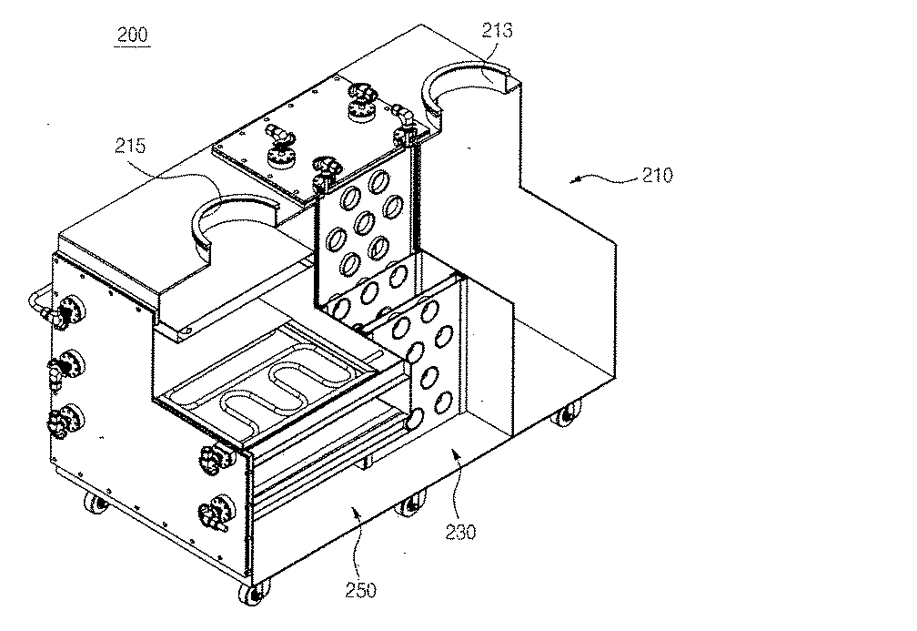
冷却部200は、冷却ハウジング210と第1冷却板230及び第2冷却板250を含んで構成される。
冷却部200は、プラズマ処理部100で分解及び解離されて冷却ハウジング210の内部に流入する工程廃ガスを、第1冷却板230で一次冷却して副産物の一部を捕集し、第2冷却板250で二次冷却して反応副産物を粉末形態で捕集する。
冷却ハウジング210は、ハウジング本体211と廃ガス流入口213と廃ガス流出口215と第1隔壁217及び第2隔壁219を含んで構成される。
The
The
The cooling
ハウジング本体211は、内部が中空の略ボックス形状に形成され、四角ボックス形状に形成することができる。
例えば、ハウジング本体211は、一側壁211aと他の側壁211bと前側壁211cと後側壁211dと本体上板211e及び本体下板211fを含んで形成することができる。
ハウジング本体211は、第1冷却板230と第2冷却板250を内部に収容して工程廃ガスが流れる空間を提供する。
廃ガス流入口213はハウジング本体211の本体上板211eの一側に形成されて、反応チャンバ150または連結管170が連結される。廃ガス流入口213は、反応チャンバ150で処理された工程廃ガスが冷却ハウジング210の内部に流入する経路を提供する。
廃ガス流出口215は、ハウジング本体211の本体上板211eの他側に形成されて、トラップ部300が連結される。廃ガス流出口215は、反応副産物が除去された工程廃ガスがトラップ部300に流出する経路を提供する。
The housing body 211 is formed in a substantially box shape with a hollow inside, and can be formed in a square box shape.
For example, the housing main body 211 can be formed including one
The housing main body 211 accommodates the
The
The
第1隔壁217は板状であり、ハウジング本体211の一側壁211aより狭い幅(w)を有して形成される。
第1隔壁217は廃ガス流入口213を中心に反対側でハウジング本体211の一側壁211aと対向する位置に形成される。すなわち、第1隔壁217とハウジング本体211の一側壁211aの間に廃ガス流入口213が位置する。
また、第1隔壁217は一側端がハウジング本体211の前側壁211cに接触して、他の側端がハウジング本体211の後側壁211dから離隔して形成される。
したがって、第1隔壁217はハウジング本体211の一側の空間を二つに分離する。また、第1隔壁217は、ハウジング本体211の後側壁211dとの間に工程廃ガスが流れる第1隔壁ホール217aを形成する。
第1隔壁ホール217aは、廃ガス流入口213から流入した工程廃ガスが第1冷却板230に流れる通路として提供される。
The
The
The
Therefore, the
The
第2隔壁219は板状であり、ハウジング本体211の一側壁211aと同一な幅を有して形成される。
第2隔壁219は、ハウジング本体211の他の側壁211bと第1隔壁217の間に位置して、廃ガス流出口215を中心に反対側でハウジング本体211の他の側壁211bと対向する位置に形成される。すなわち、第2隔壁219とハウジング本体211の他の側壁211bの間に廃ガス流出口215が位置する。
第2隔壁219は、一側端がハウジング本体211の前側壁211cに接触し、他の側端がハウジング本体211の後側壁211dに接触するように形成される。
また、第2隔壁219は、前側壁211cに接触する前側端の下部角に形成される第2隔壁ホール219aを含んで形成される。
第2隔壁ホール219aは、第1冷却板230を通過した工程廃ガスが第2冷却板250に流れる通路として提供される。
The
The
The
In addition, the
The
ここで、第1隔壁217と第2隔壁219の配置は、第1隔壁ホール217aと第2隔壁ホール219aが互いに行き違うように配置される限り多様に変形することができる。
また、第2隔壁ホール219aが、第1隔壁ホール217aと同じ原理で第2隔壁219と前側壁211cの間の間隔によって形成されることが排除されるものではない。
第1冷却板230は、プラズマ処理部100で分解されて流れる工程廃ガスを冷却して反応副産物を粉末形態で捕集する。
第1冷却板230は内部が中空である六面体板状であり、一側面から他側面に貫通する複数個のガス貫通管231を具備して形成される。
Here, the arrangement of the
In addition, it is not excluded that the
The
The
第1冷却板230は、上板と下板及び側板を結合して形成することができる。
また、第1冷却板230は、上部に第1冷却水流入口233と第1冷却水流出口235を含んで形成される。
第1冷却板230は、第1隔壁217と第2隔壁219の間の幅と高さに対応する面積を有し、第1隔壁217及び第2隔壁219と直交するように位置する。
また、第1冷却板230は、ハウジング本体211の前側壁211cと後側壁211dの間に複数個が一直線に離隔して配置され、すべて前側壁211cと平行に配置される。
ガス貫通管231は、中心軸が前側壁211cおよび後側壁211dを向くように具備され、中心軸が水平になるように具備することができる。
ガス貫通管231は、接する他の第1冷却板230のガス貫通管231と互いに貫通しないように形成される。
すなわち接する二つの第1冷却板230に形成されるガス貫通管231は、前側壁211cと後側壁211dを向く方向に行き違うように配置される。
これによって工程廃ガスの移動経路が増えるので、冷却効率を高めることができる。
さらに、工程廃ガスは第1冷却板230の間をジグザグに流れながらガス貫通管231を通過するので、第1冷却板230と接触面積が増加する。
The
In addition, the
The
The plurality of
The gas through
The gas through
That is, the
As a result, the number of process waste gas movement paths increases, so that the cooling efficiency can be increased.
Furthermore, since the process waste gas passes through the gas through
一方、第1冷却板230は、内部を流れる冷却水によって冷却され、ガス貫通管231を通過して流れる工程廃ガスを冷却し、粉末状となった副生成物が捕集されるようにする。
冷却水は、第1冷却水流入口233に流入して第1冷却板230の内部を流れた後、第1冷却水流出口235に流出する。
第1冷却水流入口233と第1冷却水流出口235は、それぞれ第1冷却板230の上板、下板または側板のいずれか一つの位置に形成することができる。
第2冷却板250は、第1冷却板230を経て流入する工程廃ガスが、冷却管255を流れる冷却水によって冷却されるメッシュ網251を経て冷却され、析出した反応副産物が捕集されるようにする。
第2冷却板250は、第2隔壁219と冷却ハウジング210の他の側壁211bの間で水平を成すように位置して、複数個が上下方向に離隔して配置される。
On the other hand, the
The cooling water flows into the first
The first cooling
In the
A plurality of the
また、第2冷却板250は、他の側壁211bと第2隔壁219の間の距離より狭い幅とハウジング本体211の前側壁211cと後側壁211dの間の距離に対応する長さを有するように形成される。ここで、第2冷却板250の大きさは、メッシュ網251の大きさを意味する。
これによって、第2冷却板250は他の側壁211bまたは第2隔壁219との間に間隔を形成するようになる。この間隔は、工程廃ガスが流れる第2冷却ホール250aとして提供される。
したがって、冷却効率の向上のために、第2冷却ホール250aはジグザグ形態に配置されることが好ましい。そのために、複数個の第2冷却板250は冷却ハウジング210の他の側壁211bと第2隔壁219に相互に接するように形成される。
第2冷却板250は、メッシュ網251と支持バー253と冷却管255を含んで形成される。
工程廃ガスは、一部がメッシュ網251の間を通過しながら上部に流れて、残りの一部は第2冷却ホール250aを通過しながらジグザグに流れるようになる。
したがって、第2冷却ホール250aは、工程廃ガスがメッシュ網251と接触する時間を増加させて、メッシュ網251に多くの反応副産物が積もった場合にも工程廃ガスの流れを円滑にする。
In addition, the
Accordingly, the
Therefore, the
The
Part of the process waste gas flows upward while passing between the mesh nets 251, and the remaining part of the process waste gas flows zigzag while passing through the second cooling holes 250 a.
Therefore, the
ここで、メッシュ網251はワイヤーが格子形状に結合されて上下に貫通する複数個のホールが形成される一般的なメッシュ網または平板形状で、上下に貫通する複数個のホールが形成される打孔板で成り立つことができる。
メッシュ網251は、上部メッシュ網251aと下部メッシュ網251bを含み、垂直方向に互いに離隔して形成され得る。
これとは異なり、メッシュ網251は上部メッシュ網251aまたは下部メッシュ網251bだけで形成することができることはもちろんである。
工程廃ガスは、メッシュ網251の多数のホールを上下に貫通しながら冷却される。
Here, the
The
Unlike this, the
The process waste gas is cooled while penetrating a number of holes in the mesh net 251 up and down.
支持バー253はバー形状に形成され、上部メッシュ網251aと下部メッシュ網251bの両側をそれぞれ支持する。支持バー253は、第2隔壁219と他の側壁211bに両端が結合されてメッシュ網251を支持する。
冷却管255は、内部が中空であるパイプで形成される。冷却管255は、多数回折り曲げられた形状(ジグザグ形状)で具備されて、両側端は冷却ハウジング210の他の側壁211bの外部に延長するように形成される。冷却管255は、上部メッシュ網251aと下部メッシュ網251bの間に位置する。
The
The
メッシュ網251が、上部メッシュ網251aまたは下部メッシュ網251bだけで形成される場合、メッシュ網251の上面または下面に結合して具備される。
冷却管255は、外部の冷却水供給管(図示せず)と連結されて、冷却水の供給を受けるように具備される。
これによって、冷却管255に接触する上部メッシュ網251aと下部メッシュ網251bが冷却される。
工程廃ガスは、冷却管255とメッシュ網251を経ながら冷却されるので、冷却水と直接的な接触なしに効率的な反応副産物の捕集ができる。
When the
The
Accordingly, the upper mesh net 251a and the lower mesh net 251b that are in contact with the
Since the process waste gas is cooled through the
トラップ部300は、トラップハウジング310及びトラップ板330を含んで形成される。
トラップ部300は、冷却部200を通過して上昇する工程廃ガスに含まれている反応副産物を冷却して追加で捕集する。
トラップ部300は、第2冷却板250を通過する工程廃ガスに反応副産物の量が少ない場合には、省略することができる。
The
The
The
トラップハウジング310は、内部が中空である筒形状に形成され、円筒形状に形成され得る。
トラップハウジング310は、トラップ流入口311とトラップ流出口313を具備して形成される。
トラップハウジング310のトラップ流入口311は、トラップハウジング310の下部に形成され、ハウジング本体211の廃ガス流出口215と結合される。
トラップ流入口311は、廃ガス流出口215から流出する工程廃ガスがトラップハウジング310の内部に流入するようにする。
トラップ流出口313は、トラップハウジング310の上部に形成され、反応部400と結合される。
トラップハウジング310の内部を通過した工程廃ガスは、トラップ流出口313を通じて流出して反応部400に流入する。
The
The
A
The
The
The process waste gas that has passed through the inside of the
トラップ板330は、第1トラップ板331と第2トラップ板333を含んで形成される。
トラップ板330は、第1トラップ板331と第2トラップ板333がトラップハウジング310の内部で垂直方向に互いに離隔するように相互に積層して形成される。
第1トラップ板331と第2トラップ板333は、別途のトラップ支持棒335によって支持されて離隔される。
トラップ板330は、下部から上部に流れながら接触する工程廃ガスに含まれている反応副産物を捕集する。
第1トラップ板331は、トラップハウジング310の内部水平断面に対応する形状に形成され、外周面がトラップハウジングの内周面と隣接するか接触するように形成される。
また、第1トラップ板331は、中央部分に形成される第1トラップホール331aを含んで形成される。
第1トラップホール331aは、トラップ流入口311を通過して流入する工程廃ガスが上部に流れる通路として提供される。
The
The
The
The
The
The
The
工程廃ガスは、トラップ流入口311を通じて流入した後に第1トラップ板331の下面と接触した後に、または直接第1トラップホール331aを通過して上昇する。
第2トラップ板333は、トラップハウジング310の内部水平断面に対応する形状に形成され、第1トラップ板331より小さな直径を有するように形成される。
したがって、第2トラップ板333は、外周面がトラップハウジング310の内周面と離隔し、トラップハウジング310の内周面との間に第2トラップホール333aを形成する。
第2トラップホール333aは、第1トラップホール331aを通過して流入する工程廃ガスが上部に流れる通路として提供される。
工程廃ガスは、第1トラップホール331aを通じて上昇し第2トラップ板333の下面と接触した後に、第2トラップホール333aを通過して上昇する。
第1トラップ板331と第2トラップ板333が相互に積層して形成されるので、工程廃ガスは第1トラップホール331aと第2トラップホール333aを順次に通過しながらジグザグに第1トラップ板331と第2トラップ板333の間を流れる。
The process waste gas rises after flowing through the
The
Accordingly, the
The
The process waste gas rises through the
Since the
一方、本実施形態において、トラップ部300には上述した注入チャンバ130、反応チャンバ150のように、触媒ガスが注入されるように多数の第3触媒ガス注入管153をさらに連結することもできる。
触媒ガスは、アンモニア(NH3)を含むことができる。
これによって、トラップ部300内で未反応工程廃ガスの処理効率を向上させることができる。
On the other hand, in the present embodiment, a large number of third catalyst
The catalyst gas can include ammonia (NH 3 ).
Thereby, the processing efficiency of unreacted process waste gas can be improved in the
反応部400は、反応ハウジング410と支持板430及びアミン系物質層450を含んで形成される。
反応部400は、冷却部200またはトラップ部300の上部に位置して、冷却部200またはトラップ部300を通り過ぎた工程廃ガスが流入する。
反応部400は、工程廃ガス含まれている水溶性ガスを酸塩基反応によってアミン系物質層450に固定して除去する。
The
The
The
反応ハウジング410は内部が中空である筒形状に形成され、円筒形状に形成する。
反応ハウジング410は、反応流入口411と反応流出口413を具備する。
反応ハウジング410の反応流入口411は、反応ハウジング410の下部に形成され、トラップハウジング310のトラップ流出口313と連通して、トラップ流出口313から流出する工程廃ガスが反応ハウジング410の内部に流入する。
反応流出口413は、反応ハウジング410の内部を通り過ぎた工程廃ガスを外部に排出する通路として提供される。
反応流出口413は、反応ハウジング410の一側に具備され、アミン系物質層450の最上層の上側ならどこに設置してもよい。
The
The
A
The
The
一方、反応ハウジング410は、上部を開口して設置することができ、この場合上部開口を密封する反応上部板415をさらに含んで構成される。
ここで、反応流出口413が反応上部板415に形成され得る。
反応上部板415は、反応ハウジング410の上部開口を開閉するように具備される。
反応上部板415は、反応ハウジング410内に位置するアミン系物質層450の交換が必要な場合、反応ハウジング410から一時的に分離して反応ハウジング410の上部を開放する。
Meanwhile, the
Here, a
The reaction
The reaction
支持板430は板状に形成され、上面から下面に貫通する多数の支持ホール431を具備して形成される。
支持板430は、外周面に沿って形成される垂直板433をさらに具備して形成され得る。
支持板430は複数個形成され、垂直方向に互いに離隔して位置する。
支持板430は上部にアミン系物質層450が配置され、支持ホール431を通過して上昇する工程廃ガスがアミン系物質層450と接触させる。
垂直板433は支持板430の外周から下方に延長して形成され、アミン系物質層450の外周によって支持される。
The
The
A plurality of
The
The
アミン系物質層450はアミン系物質の粉末または固まりが積層して、内部に多数の氣孔を含んで形成される。
アミン系物質層は、アミン系物質自体で形成されるか、アミン系物質及びそれを一定形態を維持するように支持する他の物質が混合して形成され得る。
The amine-based
The amine-based material layer may be formed of the amine-based material itself or a mixture of the amine-based material and another material that supports the material to maintain a certain form.
アミン系物質は、カルバミド(ウレア)、アミノ酪酸、ジフェニルアミン、3,4−又は3,5−ジアミノ安息香酸、グルタミン酸、ラウリルアミン(N−ドデシルアミン)、メチルヘキシルアミン、ニコチンプトレスシンステアリルアミン(オクタデシルアミン)及び牛脂アミンの中から選ばれる少なくとも一つの物質を含むことができる。
アミン系物質層450は、下部に流入して上部に流れる工程廃ガスに含まれている水溶性ガスを捕集する。
Amine substances include carbamide (urea), aminobutyric acid, diphenylamine, 3,4- or 3,5-diaminobenzoic acid, glutamic acid, laurylamine (N-dodecylamine), methylhexylamine, nicotine putrescine stearylamine (octadecyl). Amine) and at least one substance selected from beef tallow amine.
The amine-based
アミン系物質は、工程廃ガス内に含まれているハロゲン化水素化合物のような水溶性ガスと酸塩基反応を起こして、水溶性ガスを捕集する。
例えば、アミン系物質にカルバミドを使用する場合、カルバミドは下記の主反応式または副反応式によってハロゲン化水素化合物と反応してハロゲン化水素化合物を捕集する。
主反応式によると、ハロゲン化水素化合物はカルバミドのアミノ基の水素原子と結合し、ハロゲン族元素による置換は発生しない。
カルバミドは、ハロゲン化水素化合物と反応して結合することによって粉末状態がエマルジョン状態に変化する。また、副反応式によると、カルバミドは熱がある場合にカルボニル基とアミノ基に分解されて、カルボニル基はCO2に転換されてアミノ基はハロゲン化水素化合物と反応してNH4Xに変換される。
The amine-based material causes an acid-base reaction with a water-soluble gas such as a hydrogen halide compound contained in the process waste gas, and collects the water-soluble gas.
For example, when carbamide is used as the amine-based material, the carbamide collects the hydrogen halide compound by reacting with the hydrogen halide compound according to the following main reaction formula or side reaction formula.
According to the main reaction formula, the hydrogen halide compound is bonded to the hydrogen atom of the amino group of carbamide, and substitution with a halogen group element does not occur.
The carbamide reacts with and binds to the hydrogen halide compound to change the powder state into an emulsion state. In addition, according to the side reaction formula, carbamide is decomposed into a carbonyl group and an amino group when heated, the carbonyl group is converted into CO 2 , and the amino group reacts with a hydrogen halide compound to be converted into NH 4 X. Is done.
(主反応式)
(副反応式)
次に、本発明の一実施形態による工程廃ガス処理用スクラバの作用について説明する。
半導体工程などで発生する工程廃ガスは、工程廃ガス注入管131を通じて注入チャンバ130の内部に流入する。
プラズマトーチ110は、プラズマ火炎を形成して注入チャンバ130に提供する。
工程廃ガスは、注入チャンバ130の内部でプラズマ火炎と接触して、反応チャンバ150に流入する。
工程廃ガスは、プラズマ火炎と接触しながら反応して分解及び解離される。
Next, the operation of the process waste gas treatment scrubber according to the embodiment of the present invention will be described.
Process waste gas generated in a semiconductor process or the like flows into the
The
Process waste gas contacts the plasma flame inside the
Process waste gas reacts in contact with the plasma flame and is decomposed and dissociated.
工程廃ガスは、連結管170を通じて冷却されながら一部が反応副産物に形成され、冷却部200に流入する。
工程廃ガスは、冷却ハウジング210の一側に形成される廃ガス流入口213を通じてハウジング本体211の一側壁211aと第1隔壁217の間に流入する。
工程廃ガスは、また第1隔壁217の第1隔壁ホール217aを通じて第1隔壁217と第2隔壁219の間の空間に流れながら第1冷却板230と接触する。
第1冷却板230は、流入する工程廃ガスと接触しながら工程廃ガスを冷却して反応副産物を捕集する。
第1冷却板230は、第1冷却水流入口233から流入して内部を流れる冷却水によって冷却され、持続的に工程廃ガスを冷却して反応副産物を捕集する。
工程廃ガスは、第1冷却板230に形成されるガス貫通管231を通過して流れる。
A part of the process waste gas is formed as a reaction byproduct while being cooled through the
The process waste gas flows between the one
The process waste gas contacts the
The
The
The process waste gas flows through the gas through
工程廃ガスは、第1冷却板230をすべて通過した後、第2隔壁219に形成される第2隔壁ホール219aを通じて第2隔壁219とハウジング本体211の他の側壁211bの間の空間に流入する。
第2冷却板250は、工程廃ガスがメッシュ網251と冷却管255と接触して通過するようにしながら冷却して反応副産物を捕集する。
第2冷却板250は、一側と他側に第2冷却ホール250aを形成して、工程廃ガスが第2冷却板250の間をジグザグに流れるようにしながらメッシュ網251と接触する時間を増加させる。
工程廃ガスは、第2冷却板250をすべて通過した後、廃ガス流出口215を通じて流出してトラップ流入口311を通じてトラップハウジング310の内部に流入する。
The process waste gas passes through the
The
The
The process waste gas passes through the
トラップ部300は、トラップ流入口311を通じて流入する工程廃ガスがトラップ板330と接触しながら上部に流れるようにする。
トラップ板330は、工程廃ガスが第1トラップ板331及び第2トラップ板333と接触しながら冷却されるようにして反応副産物を追加に捕集する。
工程廃ガスは、第1トラップ板331の第1トラップホール331aと第2トラップ板333の第2トラップホール333aを相互に通過しながらジグザグに流れるようになる。
工程廃ガスは、トラップ板330をすべて通過した後、トラップハウジング310のトラップ流出口313を通じて流出し、反応ハウジング410の反応流入口411を通じて反応ハウジング410の内部に流入する。
反応部400のアミン系物質層450は、工程廃ガスと接触しながら前述した主反応式と副反応式によって工程廃ガスに含まれているハロゲン化水素化合物のような水溶性ガスと酸塩基反応を進行して水溶性ガスを捕集して固定する。
工程廃ガスは、アミン系物質層450を通過した後、反応ハウジング410の反応流出口413を通じて外部に流出する。
The
The
The process waste gas flows in a zigzag manner while passing through the
The process waste gas passes through the
The amine-based
The process waste gas passes through the amine-based
以上、説明したとおり、本発明の一実施形態による工程廃ガス処理用スクラバは、冷却部200の第1冷却板230と第2冷却板250に供給されて循環する冷却水以外に別途の水を使用せず、工程廃ガスとの直接接触がないので廃水排出が全くなく、廃水を処理するための水処理施設を必要としない。
したがって、本発明の工程廃ガス処理用スクラバは、親環境的な方法で廃ガスを処理する。
さらに、本発明の工程廃ガス処理用スクラバは、プラズマのような熱エネルギーを用いて廃ガスを完全に分解、解離させて、分解、解離された廃ガスを冷却して粉末状の反応副産物(パウダー副産物)に変換させることによって、廃ガスの排出濃度をさらに低くすることができる。
また、本発明の一実施形態による工程廃ガス処理用スクラバは、概して電気のみを使用するため管理が容易で、運用費用を減少させることができる。
As described above, the process waste gas treatment scrubber according to the embodiment of the present invention supplies water other than the cooling water supplied to the
Accordingly, the process waste gas treatment scrubber of the present invention treats waste gas in an environmentally friendly manner.
Furthermore, the process waste gas processing scrubber of the present invention completely decomposes and dissociates the waste gas using thermal energy such as plasma, cools the decomposed and dissociated waste gas, and forms a powdery reaction byproduct ( By converting it into a powder byproduct, the exhaust gas concentration can be further reduced.
In addition, the process waste gas treatment scrubber according to the embodiment of the present invention is easy to manage because it generally uses only electricity, and can reduce operation costs.
図7は、本発明の他の実施形態による工程廃ガス処理用スクラバを示した図である。
本実施形態による工程廃ガス処理用スクラバは、他の構成において、図1ないし図6に記載したスクラバと大同小異だが、トラップ部の構成において差異がある。以下では、その差異に対して説明し、残りの構成に対する説明は省略する。
図7に示したとおり、本実施形態において、トラップ部は、フィルター部に代替される。
フィルター部350は略円筒形態であり、水平断面形状が円形を成すように形成される。
フィルター部350は冷却部200の下流に設置され、パウダー副産物をフィルタリングする。すなわち、フィルター部350はパウダー副産物を除去した残りの流体のみを通過させる。
FIG. 7 is a diagram showing a process waste gas treatment scrubber according to another embodiment of the present invention.
The process waste gas treatment scrubber according to the present embodiment is different from the scrubber described in FIGS. 1 to 6 in other configurations, but there is a difference in the configuration of the trap portion. Hereinafter, the difference will be described, and the description of the remaining configuration will be omitted.
As shown in FIG. 7, in this embodiment, the trap part is replaced with a filter part.
The
The
また、メッシュ網を経る冷却管255をフィルター部350に連結することで、フィルター部350の温度を一定温度に維持させることができる。
具体的に、フィルター部350は円筒状本体と、本体の内側に設置されたフィルターを含む。
円筒状本体は二重隔壁形態に形成され、二重隔壁の内側に冷却流体が一定時間滞留可能になっている。
冷却管255は、二重隔壁に連結して具備される。
フィルターは、内部に中空部が形成された形態をし、パウダー副産物を除外した残りの流体がフィルターを通過して中空部に案内されるように具備される。
フィルターの中空部は、排出管と連結して具備される。
Further, by connecting the
Specifically, the
The cylindrical main body is formed in a double partition shape, and the cooling fluid can stay inside the double partition for a certain period of time.
The
The filter has a shape in which a hollow portion is formed therein, and the remaining fluid excluding the powder by-product passes through the filter and is guided to the hollow portion.
The hollow portion of the filter is connected to the discharge pipe.
図8は、本発明のまた他の実施形態による工程廃ガス処理用スクラバを示した図及び図9は図8の工程廃ガス処理用スクラバを他の方向から見た図である。
本実施形態による工程廃ガス処理用スクラバは、他の構成において、図1ないし図6に記載のスクラバと大同小異であるが、反応チャンバ150にY字連結管138を通じて二個の冷却部200が連結され、それぞれの冷却部200にフィルター部350またはトラップ部300が連結される点に特徴がある。
すなわち、冷却部200及びフィルター部350(またはトラップ部300)が一対ずつ装着され、これらは一つの反応部400に連結される。
したがって、一側の冷却部200及びフィルター部350(またはトラップ部300)が維持補修される場合には、他の側の冷却部200及びフィルター部350(またはトラップ部300)が動作できるので、本実施形態による工程廃ガス処理用スクラバの稼動停止状態の発生を防止できる。
FIG. 8 is a view showing a process waste gas treatment scrubber according to another embodiment of the present invention, and FIG. 9 is a view of the process waste gas treatment scrubber of FIG. 8 viewed from another direction.
The process waste gas treatment scrubber according to the present embodiment is different from the scrubber shown in FIGS. 1 to 6 in other configurations, but the two cooling
That is, the
Accordingly, when the
100 プラズマ処理部
110 プラズマトーチ
130 注入チャンバ
131 工程廃ガス注入管
133 触媒ガス注入管
138 Y字連結管
150 反応チャンバ
153 第3触媒ガス注入管
170 連結管
200 冷却部
210 冷却ハウジング
211 ハウジング本体
211a 一側壁
211b 他の側壁
211c 前側壁
211d 後側壁
211e 本体上板
211f 本体下板
213 排ガス流入口
215 廃ガス流出口
217 第1隔壁
217a 第1隔壁ホール
219 第2隔壁
219a 第2隔壁ホール
230 第1冷却板
231 ガス貫通管
233 第1冷却水流入口
235 第1冷却水流出口
250 第2冷却板
250a 第2冷却ホール
251 メッシュ網
251a 上部メッシュ網
251b 下部メッシュ網
253 支持バー
255 冷却管
300 トラップ部
310 トラップハウジング
311 トラップ流入口
313 トラップ流出口
330 トラップ板
331 第1トラップ板
331a 第1トラップホール
333 第2トラップ板
333a 第2トラップホール
335 トラップ支持棒
350 フィルター部
400 反応部
410 反応ハウジング
411 反応流入口
413 反応流出口
415 反応上部板
430 支持板
431 支持ホール
433 垂直板
450 アミン系物質層
DESCRIPTION OF
Claims (13)
前記工程廃ガスを設定された熱源によって加熱する熱源部と、
前記工程廃ガスを分解及び冷却して反応副産物を捕集する冷却部とを含むことを特徴とする請求項1に記載の工程廃ガス処理用スクラバ。 Installed upstream of the reaction section in the process flow path of the process waste gas,
A heat source part for heating the process waste gas by a set heat source;
The scrubber for process waste gas treatment according to claim 1, further comprising a cooling unit that decomposes and cools the process waste gas to collect reaction byproducts.
流入する前記工程廃ガスを前記プラズマと接触させる注入チャンバ、及び
前記プラズマと前記工程廃ガスが接触し反応して前記工程廃ガスが分解される反応チャンバを含むことを特徴とする請求項2に記載の工程廃ガス処理用スクラバ。 The heat source unit is a plasma torch that generates plasma,
The method according to claim 2, further comprising: an injection chamber for bringing the inflowing process waste gas into contact with the plasma; and a reaction chamber in which the plasma and the process waste gas come into contact and react to decompose the process waste gas. The scrubber for process waste gas treatment as described.
流入した前記工程廃ガスを1次冷却して工程廃ガスの反応副産物を捕集する第1冷却板と、
前記第1冷却板を通過した前記工程廃ガスを2次冷却して前記工程廃ガスの反応副産物を捕集する第2冷却板とを含むことを特徴とする請求項2に記載の工程廃ガス処理用スクラバ。 The cooling section includes a cooling housing into which the process waste gas flowing out of the heat source section flows;
A first cooling plate for primarily cooling the inflowing process waste gas to collect reaction byproducts of the process waste gas;
The process waste gas according to claim 2, further comprising: a second cooling plate that secondarily cools the process waste gas that has passed through the first cooling plate and collects reaction byproducts of the process waste gas. Processing scrubber.
前記工程廃ガスは、前記第1冷却板をすべて経た後に、前記第2冷却板を経るように設けられたことを特徴とする請求項5に記載の工程廃ガス処理用スクラバ。 A plurality of the first and second cooling plates are provided in a stacked manner with a set interval,
6. The process waste gas treatment scrubber according to claim 5, wherein the process waste gas is provided so as to pass through the second cooling plate after passing through the first cooling plate.
前記冷却部から流出する前記工程廃ガスを冷却して反応副産物を捕集した後、前記反応部に伝達するトラップ部をさらに含むことを特徴とする請求項1に記載の工程廃ガス処理用スクラバ。 Installed between the cooling unit and the reaction unit;
2. The process waste gas processing scrubber according to claim 1, further comprising a trap unit that cools the process waste gas flowing out of the cooling unit and collects reaction byproducts and then transmits the trapped reaction product. .
内部が中空であり、前記工程廃ガスが流入する反応流入口及び前記工程廃ガスが外部に流出する反応流出口を有する反応ハウジング、
板状であり、上面から下面に貫通する多数の支持ホールを有し、前記反応ハウジング内部に垂直方向に離隔して形成された支持板、及び
前記支持板の上面に具備される前記アミン系物質層であって、前記多数の支持ホールを通じて供給される前記工程廃ガスが通過させる多孔質のアミン系物質層を含むことを特徴とする請求項1に記載の工程廃ガス処理用スクラバ。 The reaction part is
A reaction housing that is hollow inside and has a reaction inlet through which the process waste gas flows and a reaction outlet through which the process waste gas flows out;
A plate-shaped support plate having a number of support holes penetrating from the upper surface to the lower surface, and spaced apart in the vertical direction inside the reaction housing, and the amine-based material provided on the upper surface of the support plate The process waste gas treatment scrubber according to claim 1, further comprising a porous amine-based material layer through which the process waste gas supplied through the plurality of support holes passes.
カルバミド(ウレア)、アミノ酪酸、ジフェニルアミン、(N,N−ジアミノ安息香酸)、グルタミン酸、ラウリルアミン(N−ドデシルアミン)、メチルヘキシルアミン、ニコチンプトレスシンステアリルアミン(オクタデシルアミン)及び牛脂アミンの中から選ばれる少なくとも一つの物質を含むことを特徴とする請求項1に記載の工程廃ガス処理用スクラバ。 The amine material is
Among carbamide (urea), aminobutyric acid, diphenylamine, (N, N-diaminobenzoic acid), glutamic acid, laurylamine (N-dodecylamine), methylhexylamine, nicotine putrescine stearylamine (octadecylamine) and tallow amine The scrubber for process waste gas treatment according to claim 1, comprising at least one substance selected.
前記注入チャンバまたは前記反応チャンバの内部に前記工程廃ガスの反応性を増加させる触媒ガスとして、NH3を供給することを特徴とする請求項3に記載の工程廃ガス処理用スクラバ。 The process waste gas contains a halogen group element,
The process waste gas treatment scrubber according to claim 3 , wherein NH 3 is supplied as a catalyst gas for increasing the reactivity of the process waste gas into the injection chamber or the reaction chamber.
前記冷却部から流出する前記工程廃ガスのパウダー副産物をフィルタリングするフィルター部をさらに含むことを特徴とする請求項1に記載の工程廃ガス処理用スクラバ。 Installed between the cooling unit and the reaction unit;
2. The process waste gas treatment scrubber according to claim 1, further comprising a filter unit that filters powder by-products of the process waste gas flowing out of the cooling unit.
Applications Claiming Priority (2)
| Application Number | Priority Date | Filing Date | Title |
|---|---|---|---|
| KR20130112805 | 2013-09-23 | ||
| KR10-2013-0112805 | 2013-09-23 |
Publications (2)
| Publication Number | Publication Date |
|---|---|
| JP2015061725A true JP2015061725A (en) | 2015-04-02 |
| JP5878965B2 JP5878965B2 (en) | 2016-03-08 |
Family
ID=52821286
Family Applications (1)
| Application Number | Title | Priority Date | Filing Date |
|---|---|---|---|
| JP2014192927A Active JP5878965B2 (en) | 2013-09-23 | 2014-09-22 | Process waste gas scrubber |
Country Status (4)
| Country | Link |
|---|---|
| JP (1) | JP5878965B2 (en) |
| KR (1) | KR101635388B1 (en) |
| CN (1) | CN104437029B (en) |
| TW (1) | TWI568489B (en) |
Cited By (2)
| Publication number | Priority date | Publication date | Assignee | Title |
|---|---|---|---|---|
| CN111359401A (en) * | 2020-03-18 | 2020-07-03 | 江西汇和化工有限公司 | Method for co-producing amine salt by utilizing prochloraz acylated acidic tail gas |
| CN113993264A (en) * | 2021-11-05 | 2022-01-28 | 北京环境特性研究所 | Plasma torch and cooling method thereof |
Families Citing this family (14)
| Publication number | Priority date | Publication date | Assignee | Title |
|---|---|---|---|---|
| KR101926055B1 (en) * | 2017-01-10 | 2018-12-06 | 한국기계연구원 | Fast heat control reactor using plasma |
| CN107243245B (en) * | 2017-07-31 | 2023-07-04 | 赣州市恒源科技股份有限公司 | Neodymium iron boron waste recycling tail gas treatment device and control method thereof |
| KR101855511B1 (en) * | 2017-09-04 | 2018-06-11 | (주)쏠츠 | Exhaust gas purification apparatus for semiconductor production process |
| CN108176671A (en) * | 2017-12-28 | 2018-06-19 | 徐工集团工程机械有限公司 | Salt bath cleaning equipment |
| KR102189446B1 (en) * | 2018-03-16 | 2020-12-11 | (주)인트로스 | Hybrid scrubber having a plurality of scrubber chambers and a heating chamber and method for operating the hybrid scrubber |
| KR101959165B1 (en) * | 2018-04-27 | 2019-03-15 | (주)엔노피아 | Plasma waste gas processing apparatus and system |
| KR102188604B1 (en) * | 2019-04-02 | 2020-12-09 | 주식회사 미래보 | Apparatus for collecting by-product of semiconductor manufacturing process |
| KR102127952B1 (en) * | 2019-12-06 | 2020-06-29 | (주)제이솔루션 | Cooling water circulation system integrated by-product collection device |
| CN112604383B (en) * | 2020-11-13 | 2022-06-17 | 北京北方华创微电子装备有限公司 | By-product treatment device of semiconductor process equipment and semiconductor process equipment |
| KR102258142B1 (en) | 2021-01-21 | 2021-05-31 | 주식회사 에이치티아이티 | Apparatus for treating hazardous gas |
| KR102311939B1 (en) * | 2021-04-28 | 2021-10-13 | 주식회사 미래보 | Apparatus for multi trapping of reaction by-product for semiconductor process |
| KR102330326B1 (en) * | 2021-05-25 | 2021-11-24 | 주식회사 원익홀딩스 | Cooling assembly for wet tower |
| CN114200080A (en) * | 2021-11-30 | 2022-03-18 | 刘杰 | Boiler waste gas detection device |
| KR102523983B1 (en) * | 2022-12-28 | 2023-04-21 | 영진아이엔디(주) | Catalytic plasma scrubber having thermal accumulator and method for treating waste gas using the same |
Citations (14)
| Publication number | Priority date | Publication date | Assignee | Title |
|---|---|---|---|---|
| JPS5351671U (en) * | 1976-10-05 | 1978-05-02 | ||
| JPS62256908A (en) * | 1986-04-30 | 1987-11-09 | Hitachi Ltd | Ultrafine particle production device |
| JP3007662U (en) * | 1994-08-10 | 1995-02-21 | 株式会社赤松電機製作所 | Louver of dust remover |
| JPH09248419A (en) * | 1996-03-13 | 1997-09-22 | Takuma Co Ltd | Waste gas treatment method for ash melting furnace and apparatus therefor |
| JP2000272914A (en) * | 1999-03-26 | 2000-10-03 | Hirobe:Kk | Thermally conductive activated carbon substance and gas treating apparatus |
| JP2003265916A (en) * | 2002-03-15 | 2003-09-24 | Ichiro Yanaka | Dust collecting vessel |
| JP2005013866A (en) * | 2003-06-25 | 2005-01-20 | Tokyo Electron Ltd | Trap device, processing system, and impurity removal method |
| JP2005040766A (en) * | 2003-07-25 | 2005-02-17 | Kanto Denka Kogyo Co Ltd | Treatment agent and treatment method for exhaust gas containing acid gas and / or hydrocarbon |
| JP2008212205A (en) * | 2007-02-28 | 2008-09-18 | Azumi Roshi Kk | Deodorizing sheet and honeycomb filter |
| WO2009125457A1 (en) * | 2008-04-11 | 2009-10-15 | カンケンテクノ株式会社 | Process for treatment of exhaust gas containing both silane gas and fluorine gas and exhasut gas treatment facility for the process |
| JP2010179249A (en) * | 2009-02-06 | 2010-08-19 | Hitachi Ltd | Apparatus and method for decomposing perfluoro compound |
| WO2010092671A1 (en) * | 2009-02-10 | 2010-08-19 | ズードケミー触媒株式会社 | Agent and method for detoxifying metal hydride-containing exhaust gas |
| JP2010240595A (en) * | 2009-04-07 | 2010-10-28 | Kanken Techno Co Ltd | Exhaust gas abatement system |
| JP2012121018A (en) * | 2010-11-16 | 2012-06-28 | National Institute Of Advanced Industrial Science & Technology | Method for removing and recovering gaseous halide and removing/recovering agent of gaseous halide |
Family Cites Families (8)
| Publication number | Priority date | Publication date | Assignee | Title |
|---|---|---|---|---|
| JPH037662U (en) * | 1989-06-07 | 1991-01-24 | ||
| JP3737082B2 (en) * | 2001-12-04 | 2006-01-18 | 株式会社荏原製作所 | Exhaust gas treatment method and apparatus |
| JP2005205330A (en) * | 2004-01-23 | 2005-08-04 | Kanken Techno Co Ltd | Plasma decomposition treatment method of perfluoro compound exhaust gas, plasma decomposition treatment apparatus using the method, and exhaust gas treatment system equipped with the plasma decomposition treatment apparatus |
| US7846407B2 (en) * | 2006-04-07 | 2010-12-07 | Liang Hu | Self-concentrating absorbent for acid gas separation |
| CN101279187A (en) * | 2007-04-06 | 2008-10-08 | 严桓燮 | Device and method for eliminating fluorinated gases |
| JP2009082893A (en) * | 2007-10-03 | 2009-04-23 | Kanken Techno Co Ltd | Exhaust gas treatment equipment |
| CN202751933U (en) * | 2012-08-27 | 2013-02-27 | 浙江大学 | Four-section type sludge drying off-gas treatment system |
| CN202823131U (en) * | 2012-10-25 | 2013-03-27 | 无锡宇吉科技有限公司 | Waste gas purification and recovery device |
-
2014
- 2014-09-02 KR KR1020140116406A patent/KR101635388B1/en active Active
- 2014-09-17 CN CN201410475214.4A patent/CN104437029B/en active Active
- 2014-09-22 JP JP2014192927A patent/JP5878965B2/en active Active
- 2014-09-23 TW TW103132828A patent/TWI568489B/en active
Patent Citations (14)
| Publication number | Priority date | Publication date | Assignee | Title |
|---|---|---|---|---|
| JPS5351671U (en) * | 1976-10-05 | 1978-05-02 | ||
| JPS62256908A (en) * | 1986-04-30 | 1987-11-09 | Hitachi Ltd | Ultrafine particle production device |
| JP3007662U (en) * | 1994-08-10 | 1995-02-21 | 株式会社赤松電機製作所 | Louver of dust remover |
| JPH09248419A (en) * | 1996-03-13 | 1997-09-22 | Takuma Co Ltd | Waste gas treatment method for ash melting furnace and apparatus therefor |
| JP2000272914A (en) * | 1999-03-26 | 2000-10-03 | Hirobe:Kk | Thermally conductive activated carbon substance and gas treating apparatus |
| JP2003265916A (en) * | 2002-03-15 | 2003-09-24 | Ichiro Yanaka | Dust collecting vessel |
| JP2005013866A (en) * | 2003-06-25 | 2005-01-20 | Tokyo Electron Ltd | Trap device, processing system, and impurity removal method |
| JP2005040766A (en) * | 2003-07-25 | 2005-02-17 | Kanto Denka Kogyo Co Ltd | Treatment agent and treatment method for exhaust gas containing acid gas and / or hydrocarbon |
| JP2008212205A (en) * | 2007-02-28 | 2008-09-18 | Azumi Roshi Kk | Deodorizing sheet and honeycomb filter |
| WO2009125457A1 (en) * | 2008-04-11 | 2009-10-15 | カンケンテクノ株式会社 | Process for treatment of exhaust gas containing both silane gas and fluorine gas and exhasut gas treatment facility for the process |
| JP2010179249A (en) * | 2009-02-06 | 2010-08-19 | Hitachi Ltd | Apparatus and method for decomposing perfluoro compound |
| WO2010092671A1 (en) * | 2009-02-10 | 2010-08-19 | ズードケミー触媒株式会社 | Agent and method for detoxifying metal hydride-containing exhaust gas |
| JP2010240595A (en) * | 2009-04-07 | 2010-10-28 | Kanken Techno Co Ltd | Exhaust gas abatement system |
| JP2012121018A (en) * | 2010-11-16 | 2012-06-28 | National Institute Of Advanced Industrial Science & Technology | Method for removing and recovering gaseous halide and removing/recovering agent of gaseous halide |
Cited By (3)
| Publication number | Priority date | Publication date | Assignee | Title |
|---|---|---|---|---|
| CN111359401A (en) * | 2020-03-18 | 2020-07-03 | 江西汇和化工有限公司 | Method for co-producing amine salt by utilizing prochloraz acylated acidic tail gas |
| CN113993264A (en) * | 2021-11-05 | 2022-01-28 | 北京环境特性研究所 | Plasma torch and cooling method thereof |
| CN113993264B (en) * | 2021-11-05 | 2023-11-14 | 北京环境特性研究所 | Plasma torch and cooling method thereof |
Also Published As
| Publication number | Publication date |
|---|---|
| CN104437029B (en) | 2016-11-30 |
| KR20150033535A (en) | 2015-04-01 |
| KR101635388B1 (en) | 2016-07-08 |
| JP5878965B2 (en) | 2016-03-08 |
| TW201511820A (en) | 2015-04-01 |
| TWI568489B (en) | 2017-02-01 |
| CN104437029A (en) | 2015-03-25 |
Similar Documents
| Publication | Publication Date | Title |
|---|---|---|
| JP5878965B2 (en) | Process waste gas scrubber | |
| RU2604233C2 (en) | Air contamination monitoring system | |
| CN1326767C (en) | Nox, Hg, and SO2 removal using ammonia | |
| KR101224439B1 (en) | A system and method for enhanced removal of co2 from a mixed gas stream via use of a catalyst | |
| US20130280154A1 (en) | Apparatus and method for treating perfluoro-compound | |
| KR101774710B1 (en) | Hybrid Dry Hazardous Gas Treatment Apparatus Using Plasma and Catalyst and Operation Method Thereof | |
| KR100766749B1 (en) | Large-capacity exhaust gas treatment method containing perfluorinated compound gas and apparatus for treating same | |
| KR101376238B1 (en) | Scrubber for processing waste gas | |
| US11951440B2 (en) | Photochemical method and device for volatile organic compound pollution control | |
| US20170326496A1 (en) | Method of treating gas and gas treatment device | |
| CN108704465A (en) | Vacuum ultraviolet cooperates with effective chlorine for the method and device of flue gas and desulfurizing and denitrifying | |
| KR20120021651A (en) | Apparatus and method for pfcs gas decomposition | |
| KR101791478B1 (en) | Treating system of waste gas | |
| CN107497265B (en) | Integrated flue gas purification system and method for ozone-assisted microwave excitation of fly ash-induced free radicals | |
| KR101641855B1 (en) | Scrubber for treating processing waste gas | |
| KR101977928B1 (en) | Device and Process for multi-stage of PFC treating reaction occurring in at least two reaction modules including catalytic reactor and acidic gas-removing reactor | |
| CN206444423U (en) | A kind of UV photoions waste gas purification apparatus | |
| KR102880540B1 (en) | Perfluorinated compounds reduction system | |
| KR101564579B1 (en) | Scrubber for waste gases removing by combination of gas-liquid contact device with multi function | |
| KR20110017126A (en) | Reactor Assembly for Hybrid Scrubber | |
| CN220424996U (en) | Apparatus for treating flue gas | |
| KR20140139888A (en) | Sulphur hexafluoride treatment system | |
| KR101633404B1 (en) | Apparatus for processing waste gas | |
| ES2643066T3 (en) | Device for treating at least one flow of gaseous effluents | |
| KR101745908B1 (en) | Scrubber |
Legal Events
| Date | Code | Title | Description |
|---|---|---|---|
| A131 | Notification of reasons for refusal |
Free format text: JAPANESE INTERMEDIATE CODE: A131 Effective date: 20151006 |
|
| A521 | Request for written amendment filed |
Free format text: JAPANESE INTERMEDIATE CODE: A523 Effective date: 20160106 |
|
| TRDD | Decision of grant or rejection written | ||
| A01 | Written decision to grant a patent or to grant a registration (utility model) |
Free format text: JAPANESE INTERMEDIATE CODE: A01 Effective date: 20160126 |
|
| A61 | First payment of annual fees (during grant procedure) |
Free format text: JAPANESE INTERMEDIATE CODE: A61 Effective date: 20160129 |
|
| R150 | Certificate of patent or registration of utility model |
Ref document number: 5878965 Country of ref document: JP Free format text: JAPANESE INTERMEDIATE CODE: R150 |
|
| R250 | Receipt of annual fees |
Free format text: JAPANESE INTERMEDIATE CODE: R250 |
|
| R250 | Receipt of annual fees |
Free format text: JAPANESE INTERMEDIATE CODE: R250 |
|
| R250 | Receipt of annual fees |
Free format text: JAPANESE INTERMEDIATE CODE: R250 |
|
| R250 | Receipt of annual fees |
Free format text: JAPANESE INTERMEDIATE CODE: R250 |
|
| R250 | Receipt of annual fees |
Free format text: JAPANESE INTERMEDIATE CODE: R250 |
|
| R250 | Receipt of annual fees |
Free format text: JAPANESE INTERMEDIATE CODE: R250 |
|
| R250 | Receipt of annual fees |
Free format text: JAPANESE INTERMEDIATE CODE: R250 |
|
| R250 | Receipt of annual fees |
Free format text: JAPANESE INTERMEDIATE CODE: R250 |