JP2013179003A - Lighting fixture - Google Patents

Lighting fixture Download PDF

Info

Publication number
JP2013179003A
JP2013179003A JP2012043003A JP2012043003A JP2013179003A JP 2013179003 A JP2013179003 A JP 2013179003A JP 2012043003 A JP2012043003 A JP 2012043003A JP 2012043003 A JP2012043003 A JP 2012043003A JP 2013179003 A JP2013179003 A JP 2013179003A
Authority
JP
Japan
Prior art keywords
light source
source module
fixture
baffle
locking
Prior art date
Legal status (The legal status is an assumption and is not a legal conclusion. Google has not performed a legal analysis and makes no representation as to the accuracy of the status listed.)
Pending
Application number
JP2012043003A
Other languages
Japanese (ja)
Inventor
Kenichi Ito
賢一 伊藤
Current Assignee (The listed assignees may be inaccurate. Google has not performed a legal analysis and makes no representation or warranty as to the accuracy of the list.)
Toshiba Lighting and Technology Corp
Original Assignee
Toshiba Lighting and Technology Corp
Priority date (The priority date is an assumption and is not a legal conclusion. Google has not performed a legal analysis and makes no representation as to the accuracy of the date listed.)
Filing date
Publication date
Application filed by Toshiba Lighting and Technology Corp filed Critical Toshiba Lighting and Technology Corp
Priority to JP2012043003A priority Critical patent/JP2013179003A/en
Priority to EP13156785.1A priority patent/EP2634475A1/en
Priority to CN2013100646565A priority patent/CN103292230A/en
Priority to US13/779,806 priority patent/US20130223067A1/en
Publication of JP2013179003A publication Critical patent/JP2013179003A/en
Pending legal-status Critical Current

Links

Images

Classifications

    • FMECHANICAL ENGINEERING; LIGHTING; HEATING; WEAPONS; BLASTING
    • F21LIGHTING
    • F21VFUNCTIONAL FEATURES OR DETAILS OF LIGHTING DEVICES OR SYSTEMS THEREOF; STRUCTURAL COMBINATIONS OF LIGHTING DEVICES WITH OTHER ARTICLES, NOT OTHERWISE PROVIDED FOR
    • F21V19/00Fastening of light sources or lamp holders
    • F21V19/02Fastening of light sources or lamp holders with provision for adjustment, e.g. for focusing
    • FMECHANICAL ENGINEERING; LIGHTING; HEATING; WEAPONS; BLASTING
    • F21LIGHTING
    • F21SNON-PORTABLE LIGHTING DEVICES; SYSTEMS THEREOF; VEHICLE LIGHTING DEVICES SPECIALLY ADAPTED FOR VEHICLE EXTERIORS
    • F21S2/00Systems of lighting devices, not provided for in main groups F21S4/00 - F21S10/00 or F21S19/00, e.g. of modular construction
    • FMECHANICAL ENGINEERING; LIGHTING; HEATING; WEAPONS; BLASTING
    • F21LIGHTING
    • F21VFUNCTIONAL FEATURES OR DETAILS OF LIGHTING DEVICES OR SYSTEMS THEREOF; STRUCTURAL COMBINATIONS OF LIGHTING DEVICES WITH OTHER ARTICLES, NOT OTHERWISE PROVIDED FOR
    • F21V11/00Screens not covered by groups F21V1/00, F21V3/00, F21V7/00 or F21V9/00
    • F21V11/06Screens not covered by groups F21V1/00, F21V3/00, F21V7/00 or F21V9/00 using crossed laminae or strips, e.g. grid-shaped louvers; using lattices or honeycombs
    • FMECHANICAL ENGINEERING; LIGHTING; HEATING; WEAPONS; BLASTING
    • F21LIGHTING
    • F21VFUNCTIONAL FEATURES OR DETAILS OF LIGHTING DEVICES OR SYSTEMS THEREOF; STRUCTURAL COMBINATIONS OF LIGHTING DEVICES WITH OTHER ARTICLES, NOT OTHERWISE PROVIDED FOR
    • F21V17/00Fastening of component parts of lighting devices, e.g. shades, globes, refractors, reflectors, filters, screens, grids or protective cages
    • F21V17/10Fastening of component parts of lighting devices, e.g. shades, globes, refractors, reflectors, filters, screens, grids or protective cages characterised by specific fastening means or way of fastening
    • F21V17/104Fastening of component parts of lighting devices, e.g. shades, globes, refractors, reflectors, filters, screens, grids or protective cages characterised by specific fastening means or way of fastening using feather joints, e.g. tongues and grooves, with or without friction
    • FMECHANICAL ENGINEERING; LIGHTING; HEATING; WEAPONS; BLASTING
    • F21LIGHTING
    • F21VFUNCTIONAL FEATURES OR DETAILS OF LIGHTING DEVICES OR SYSTEMS THEREOF; STRUCTURAL COMBINATIONS OF LIGHTING DEVICES WITH OTHER ARTICLES, NOT OTHERWISE PROVIDED FOR
    • F21V19/00Fastening of light sources or lamp holders
    • F21V19/001Fastening of light sources or lamp holders the light sources being semiconductors devices, e.g. LEDs
    • F21V19/003Fastening of light source holders, e.g. of circuit boards or substrates holding light sources
    • F21V19/0045Fastening of light source holders, e.g. of circuit boards or substrates holding light sources by tongue and groove connections, e.g. dovetail interlocking means fixed by sliding
    • FMECHANICAL ENGINEERING; LIGHTING; HEATING; WEAPONS; BLASTING
    • F21LIGHTING
    • F21SNON-PORTABLE LIGHTING DEVICES; SYSTEMS THEREOF; VEHICLE LIGHTING DEVICES SPECIALLY ADAPTED FOR VEHICLE EXTERIORS
    • F21S8/00Lighting devices intended for fixed installation
    • F21S8/04Lighting devices intended for fixed installation intended only for mounting on a ceiling or the like overhead structures
    • FMECHANICAL ENGINEERING; LIGHTING; HEATING; WEAPONS; BLASTING
    • F21LIGHTING
    • F21VFUNCTIONAL FEATURES OR DETAILS OF LIGHTING DEVICES OR SYSTEMS THEREOF; STRUCTURAL COMBINATIONS OF LIGHTING DEVICES WITH OTHER ARTICLES, NOT OTHERWISE PROVIDED FOR
    • F21V19/00Fastening of light sources or lamp holders
    • F21V19/04Fastening of light sources or lamp holders with provision for changing light source, e.g. turret
    • FMECHANICAL ENGINEERING; LIGHTING; HEATING; WEAPONS; BLASTING
    • F21LIGHTING
    • F21YINDEXING SCHEME ASSOCIATED WITH SUBCLASSES F21K, F21L, F21S and F21V, RELATING TO THE FORM OR THE KIND OF THE LIGHT SOURCES OR OF THE COLOUR OF THE LIGHT EMITTED
    • F21Y2105/00Planar light sources
    • F21Y2105/10Planar light sources comprising a two-dimensional [2D] array of point-like light-generating elements
    • FMECHANICAL ENGINEERING; LIGHTING; HEATING; WEAPONS; BLASTING
    • F21LIGHTING
    • F21YINDEXING SCHEME ASSOCIATED WITH SUBCLASSES F21K, F21L, F21S and F21V, RELATING TO THE FORM OR THE KIND OF THE LIGHT SOURCES OR OF THE COLOUR OF THE LIGHT EMITTED
    • F21Y2113/00Combination of light sources
    • FMECHANICAL ENGINEERING; LIGHTING; HEATING; WEAPONS; BLASTING
    • F21LIGHTING
    • F21YINDEXING SCHEME ASSOCIATED WITH SUBCLASSES F21K, F21L, F21S and F21V, RELATING TO THE FORM OR THE KIND OF THE LIGHT SOURCES OR OF THE COLOUR OF THE LIGHT EMITTED
    • F21Y2115/00Light-generating elements of semiconductor light sources
    • F21Y2115/10Light-emitting diodes [LED]

Landscapes

  • Engineering & Computer Science (AREA)
  • General Engineering & Computer Science (AREA)
  • Non-Portable Lighting Devices Or Systems Thereof (AREA)
  • Fastening Of Light Sources Or Lamp Holders (AREA)

Abstract

【課題】器具本体に対して光源モジュールを容易に着脱できる照明器具を提供する。
【解決手段】実施形態の照明器具は、光源収納枠を有する本体と、前記光源収納枠の内側に設けられ、基板と前記基板上に搭載された発光素子とを有する光源モジュールと、前記光源モジュールに取り付けられた取付具と、を備えている。前記取付具は、前記光源モジュールの端部から突出して前記光源収納枠に係止して前記光源モジュールを前記本体に対して保持させる保持位置と、前記光源収納枠との係止が解除され前記光源モジュールを前記本体に対して離脱可能にする解除位置との間を移動自在な係止部を有する。
【選択図】図2
Provided is a lighting fixture in which a light source module can be easily attached to and detached from a fixture body.
A lighting fixture according to an embodiment includes a light source module including a main body having a light source storage frame, a substrate provided on the inner side of the light source storage frame, and a light emitting element mounted on the substrate, and the light source module. And a fixture attached to the. The fixture protrudes from an end portion of the light source module and is locked to the light source storage frame to hold the light source module with respect to the main body. The light source module has a locking portion that is movable between a release position that allows the light source module to be detached from the main body.
[Selection] Figure 2

Description

本発明の実施形態は、例えばLED(Light Emitting Diode)などの発光素子を光源に用いた照明器具に関する。   Embodiments described herein relate generally to a lighting fixture that uses a light emitting element such as an LED (Light Emitting Diode) as a light source.

断面T字型のバー状部材で組んだ天井枠に、照明器具、設備機器などを落とし込んだシステム天井が知られている。このシステム天井は、照明器具や設備機器の増設、移設、撤去を容易にし、デザイン自由度が高い。   There is known a system ceiling in which lighting fixtures, equipment and the like are dropped into a ceiling frame formed of bar-shaped members having a T-shaped cross section. This system ceiling facilitates the expansion, relocation, and removal of lighting fixtures and equipment, and has a high degree of design freedom.

システム天井に組み込まれる照明器具の光源として、近年、LEDモジュールが用いられるようになっており、そのLEDモジュールは照明器具本体に対してネジ止めで固定されていた。   In recent years, an LED module has been used as a light source of a lighting fixture incorporated in the system ceiling, and the LED module has been fixed to the lighting fixture body with screws.

特開2010−10106号公報JP 2010-10106 A 特開2007−122976号公報JP 2007-122976 A

器具本体に対して光源モジュールを容易に着脱できる照明器具を提供する。   Provided is a lighting fixture in which a light source module can be easily attached to and detached from a fixture body.

実施形態の照明器具は、光源収納枠を有する本体と、前記光源収納枠の内側に設けられ、基板と前記基板上に搭載された発光素子とを有する光源モジュールと、前記光源モジュールに取り付けられた取付具と、を備えている。前記取付具は、前記光源モジュールの端部から突出して前記光源収納枠に係止して前記光源モジュールを前記本体に対して保持させる保持位置と、前記光源収納枠との係止が解除され前記光源モジュールを前記本体に対して離脱可能にする解除位置との間を移動自在な係止部を有する。   A lighting apparatus according to an embodiment includes a light source module having a light source housing frame, a light source module provided inside the light source housing frame and having a substrate and a light emitting element mounted on the substrate, and attached to the light source module. And a fixture. The fixture protrudes from an end portion of the light source module and is locked to the light source storage frame to hold the light source module with respect to the main body. The light source module has a locking portion that is movable between a release position that allows the light source module to be detached from the main body.

本発明によれば、器具本体に対する光源モジュールの容易な着脱を可能にする。   According to the present invention, the light source module can be easily attached to and detached from the instrument body.

実施形態の照明器具1の外観斜視図。The external appearance perspective view of the lighting fixture 1 of embodiment. 実施形態の照明器具1の外観斜視図。The external appearance perspective view of the lighting fixture 1 of embodiment. 図2においてバッフル部材6及び設備プレート5を取り外した状態の斜視図。The perspective view of the state which removed the baffle member 6 and the equipment plate 5 in FIG. 図3に示す照明器具1の平面図。The top view of the lighting fixture 1 shown in FIG. 実施形態の照明器具1における光源モジュール12とバッフル部材6との配置関係を示す端面図。The end view which shows the arrangement | positioning relationship between the light source module 12 and the baffle member 6 in the lighting fixture 1 of embodiment. 光源モジュール12が本体2に係止している部分の拡大斜視図。The enlarged perspective view of the part which the light source module 12 latches to the main body 2. FIG. 本体2に対する光源モジュール12の取り付け高さを変えた状態の斜視図。The perspective view of the state which changed the attachment height of the light source module 12 with respect to the main body 2. FIG. 光源モジュール12の斜視図。The perspective view of the light source module 12. FIG. 光源ユニット15の斜視図。The perspective view of the light source unit 15. FIG. 光源ユニット15の一部の拡大斜視図。FIG. 3 is an enlarged perspective view of a part of the light source unit 15. 光源モジュール12における光源ユニット15を除く要素の分解斜視図。FIG. 3 is an exploded perspective view of elements other than the light source unit 15 in the light source module 12. 取付具51の斜視図。The perspective view of the fixture 51. FIG. (a)は取付具51におけるガイド部材52の斜視図であり、(b)は取付具51における可動部材53の斜視図。(A) is a perspective view of the guide member 52 in the fixture 51, (b) is a perspective view of the movable member 53 in the fixture 51. 光源モジュール12における取付具51が取り付けられた端部の拡大側面図。The enlarged side view of the edge part in which the fixture 51 in the light source module 12 was attached. バッフル部材6の斜視図。The perspective view of the baffle member 6. FIG. バッフル部材6における取付具51が取り付けられた端部の拡大斜視図。The enlarged perspective view of the edge part in which the fixture 51 in the baffle member 6 was attached. バッフル部材6におけるバッフル支持部71の斜視図。The perspective view of the baffle support part 71 in the baffle member 6. FIG. バッフル支持部71の拡大断面図。The expanded sectional view of the baffle support part 71. バッフル部材6におけるバッフル83の斜視図。The perspective view of the baffle 83 in the baffle member 6. FIG. バッフル部材6の一部の拡大斜視図。FIG. 3 is an enlarged perspective view of a part of a baffle member 6.

以下、図面を参照し、実施形態について説明する。なお、各図面中、同じ要素には同じ符号を付している。   Hereinafter, embodiments will be described with reference to the drawings. In addition, the same code | symbol is attached | subjected to the same element in each drawing.

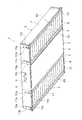
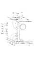
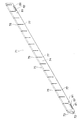
図1は、実施形態の照明器具1の外観斜視図である。
図1に表す状態における下側の面が発光面であり、その発光面を下方に向けた状態で、照明器具1はシステム天井に組み込まれる。
Drawing 1 is an appearance perspective view of lighting fixture 1 of an embodiment.
The lower surface in the state shown in FIG. 1 is a light emitting surface, and the lighting fixture 1 is incorporated in the system ceiling with the light emitting surface facing downward.

図2は、同照明器具1の発光面側を上にした斜視図である。
図3は、図2からバッフル部材6及び設備プレート5を取り除いた状態の斜視図である。
図4は、図3の状態における発光面側の平面図である。
FIG. 2 is a perspective view with the light emitting surface side of the lighting fixture 1 facing up.
FIG. 3 is a perspective view of the state in which the baffle member 6 and the equipment plate 5 are removed from FIG.
FIG. 4 is a plan view of the light emitting surface side in the state of FIG.

実施形態の照明器器具1は、本体2と、光源モジュール12と、バッフル部材6とを有する。本体2は、天井の例えば断面T字型バー状部材で組んだ枠に取り付けられる。本体2は、金属板を枠状に組み合わせて構成される。   The illuminator device 1 according to the embodiment includes a main body 2, a light source module 12, and a baffle member 6. The main body 2 is attached to a frame formed of, for example, a T-shaped bar-shaped member on the ceiling. The main body 2 is configured by combining metal plates in a frame shape.

光源モジュール12は、枠状の本体2の内側に収納されている。バッフル部材6は、光本体2の内側における光源モジュール12の発光面側に配置されている。   The light source module 12 is housed inside the frame-shaped main body 2. The baffle member 6 is disposed on the light emitting surface side of the light source module 12 inside the light main body 2.

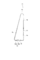
図5は、本体2内における、光源モジュール12とバッフル部材6との配置関係を表し、光源モジュール12及びバッフル部材6の長手方向の端面側から見た端面図である。図5において下側が天井側であり、光源モジュール12の発光面は、天井とは反対側(図5において上側)を向いている。   FIG. 5 is an end view showing the arrangement relationship between the light source module 12 and the baffle member 6 in the main body 2 and viewed from the end surfaces in the longitudinal direction of the light source module 12 and the baffle member 6. In FIG. 5, the lower side is the ceiling side, and the light emitting surface of the light source module 12 faces the side opposite to the ceiling (upper side in FIG. 5).

本体2は、図3及び図4に示すように、例えば四角形状に組み合わされた4つの外枠3と、外枠3の内側に設けられた内枠7とを有する。外枠3の内側は、平行に延在する2つの内枠7によって3つの空間に仕切られている。   As shown in FIGS. 3 and 4, the main body 2 includes, for example, four outer frames 3 combined in a square shape, and an inner frame 7 provided inside the outer frame 3. The inner side of the outer frame 3 is partitioned into three spaces by two inner frames 7 extending in parallel.

そのうちの2つの空間は、光源モジュール12が収納される光源収納部13であり、それら2つの光源収納部13の間には、例えばスピーカーなどが収納される設備収納部14が設けられている。設備収納部14における、天井とは反対側の開口部には、図1及び図2に示す設備プレート5が取り付けられる。   Two of these spaces are light source storage portions 13 in which the light source modules 12 are stored. Between the two light source storage portions 13, for example, an equipment storage portion 14 in which speakers and the like are stored is provided. The equipment plate 5 shown in FIG.1 and FIG.2 is attached to the opening part in the equipment storage part 14 on the opposite side to a ceiling.

光源収納部13を囲む外枠3の一部及び内枠7は光源収納枠であり、後述する取付具51を介して光源モジュール12を保持する。   A part of the outer frame 3 surrounding the light source storage unit 13 and the inner frame 7 are a light source storage frame, and hold the light source module 12 via a fixture 51 described later.

光源収納部13の平面形状は矩形状であり、その長手方向の両端に位置して互いに対向する外枠3の一部には、複数の係止孔11a〜11cが貫通孔として形成されている。同じ高さレベルに形成された1つの係止孔を対として、異なる高さに例えば3対の係止孔11a〜11cが形成されている。   The planar shape of the light source storage portion 13 is a rectangular shape, and a plurality of locking holes 11a to 11c are formed as through holes in a part of the outer frame 3 located at both ends in the longitudinal direction and facing each other. . For example, three pairs of locking holes 11a to 11c are formed at different heights, with one locking hole formed at the same height level as a pair.

天井側に最も近い位置に係止孔11aが形成され、天井から最も遠い側に係止孔11cが形成され、係止孔11aと係止孔11cとの間に係止孔11bが形成されている。係止孔11a〜11cは、光源収納部13の長手方向の両端で対向する一対の外枠3のそれぞれに、対応する係止孔11a〜11cどうしの高さレベルを一致させて形成されている。   A locking hole 11a is formed at a position closest to the ceiling side, a locking hole 11c is formed on the side farthest from the ceiling, and a locking hole 11b is formed between the locking hole 11a and the locking hole 11c. Yes. The locking holes 11 a to 11 c are formed in the pair of outer frames 3 facing each other at both ends in the longitudinal direction of the light source storage unit 13 so that the corresponding locking holes 11 a to 11 c have the same height level. .

設備収納部14の長手方向の両端に位置する外枠3の外壁面には、落下防止金具4が取り付けられている。この落下防止金具4が、天井の枠部材に引っ掛かることで、照明器具1の落下が防止される。   The fall prevention metal fitting 4 is attached to the outer wall surface of the outer frame 3 located in the both ends of the longitudinal direction of the equipment storage part 14. This fall prevention metal fitting 4 is caught by the frame member of a ceiling, and fall of the lighting fixture 1 is prevented.

次に、光源モジュール12について説明する。   Next, the light source module 12 will be described.

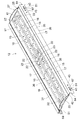
図8は、光源モジュール12の斜視図である。
光源モジュール12は、光源ユニット15と、放熱板25と、カバー27と、取付部材26とを有する。
FIG. 8 is a perspective view of the light source module 12.
The light source module 12 includes a light source unit 15, a heat dissipation plate 25, a cover 27, and an attachment member 26.

図9は、光源ユニット15の斜視図である。
図11は、放熱板25、カバー27、および取付部材26の分解斜視図である。
FIG. 9 is a perspective view of the light source unit 15.
FIG. 11 is an exploded perspective view of the heat dissipation plate 25, the cover 27, and the attachment member 26.

光源ユニット15は、図9に示すように、基板16と、基板16上に搭載(実装)された複数の発光素子17とを有する。基板16には図示しない配線が形成され、発光素子17はその配線と電気的に接続されている。   As shown in FIG. 9, the light source unit 15 includes a substrate 16 and a plurality of light emitting elements 17 mounted (mounted) on the substrate 16. A wiring (not shown) is formed on the substrate 16, and the light emitting element 17 is electrically connected to the wiring.

発光素子17は、例えば、発光ダイオード(Light Emitting Diode:LED)である。LEDの活性層の材料として、例えば窒化ガリウム(GaN)系化合物半導体を用いると、波長500ナノメータ以下の短波長光が得られる。ただし、活性層の材料は、窒化ガリウム系化合物半導体に限られるものではない。   The light emitting element 17 is, for example, a light emitting diode (LED). For example, when a gallium nitride (GaN) compound semiconductor is used as the material of the active layer of the LED, short wavelength light having a wavelength of 500 nanometers or less can be obtained. However, the material of the active layer is not limited to the gallium nitride compound semiconductor.

また、発光素子17としては、LEDのほかにも、例えば、有機発光ダイオード(Organic Light Emitting Diode:OLED)、無機エレクトロルミネッセンス(Inorganic ElectroLuminescence)発光素子、有機エレクトロルミネッセンス(Organic ElectroLuminescence)発光素子、あるいはその他の電界発光型の発光素子などを用いることができる。   In addition to the LED, the light emitting element 17 may be, for example, an organic light emitting diode (OLED), an inorganic electroluminescence light emitting element, an organic electroluminescence light emitting element, or other. An electroluminescent light emitting element or the like can be used.

実施形態においては、例えば、青色光を発光するLEDと、その青色光(励起光)を吸収して黄色光に変換する蛍光体を含む蛍光体層との組み合わせにより、発光素子17は、青色光と黄色光との混合色として白色や電球色などの光を放出する。   In the embodiment, for example, a combination of an LED that emits blue light and a phosphor layer that includes the phosphor that absorbs the blue light (excitation light) and converts the light into yellow light causes the light emitting element 17 to emit blue light. As a mixed color of light and yellow light, light such as white or light bulb color is emitted.

基板16は、細長いバー形状に形成され、その短手方向(幅方向)の両端付近のそれぞれに、長手方向に沿って複数の発光素子17が配列されている。また、基板16上には、長手方向の両端付近にコネクタ22が実装されている。コネクタ22は、上記配線を通じて発光素子17と電気的に接続されている。   The substrate 16 is formed in an elongated bar shape, and a plurality of light emitting elements 17 are arranged along the longitudinal direction near each of both ends in the lateral direction (width direction). On the substrate 16, connectors 22 are mounted near both ends in the longitudinal direction. The connector 22 is electrically connected to the light emitting element 17 through the wiring.

放熱板25は、図11に示すように、一体に設けられた主面部31と一対の側面部32とを有する金属板である。主面部31は略矩形状に形成され、その短手方向(幅方向)の両端に側面部32が一体に設けられている。主面部31の一方の面(図11において上面)は光源搭載面であり、側面部32は光源搭載面の裏側に突出しつつ、主面部31の長手方向に延在している。   As shown in FIG. 11, the heat radiating plate 25 is a metal plate having a main surface portion 31 and a pair of side surface portions 32 provided integrally. The main surface portion 31 is formed in a substantially rectangular shape, and side surface portions 32 are integrally provided at both ends in the short direction (width direction). One surface (upper surface in FIG. 11) of the main surface portion 31 is a light source mounting surface, and the side surface portion 32 extends in the longitudinal direction of the main surface portion 31 while projecting to the back side of the light source mounting surface.

主面部31の光源搭載面上には、図8に示すように、複数(図示では例えば4つ)の光源ユニット15が搭載される。光源ユニット15の基板16が、光源搭載面に対して例えばネジ止めされる。基板16における発光素子17を搭載した面の反対側の裏面が主面部31の光源搭載面に接触する。光源ユニット15の基板16は例えば金属板であり、発光素子17の発光に伴う熱は基板16を通じて効率よく放熱板25へと伝導する。   On the light source mounting surface of the main surface portion 31, as shown in FIG. 8, a plurality (for example, four in the drawing) of light source units 15 are mounted. For example, the substrate 16 of the light source unit 15 is screwed to the light source mounting surface. The back surface of the substrate 16 opposite to the surface on which the light emitting element 17 is mounted contacts the light source mounting surface of the main surface portion 31. The substrate 16 of the light source unit 15 is, for example, a metal plate, and heat accompanying light emission of the light emitting element 17 is efficiently conducted to the heat radiating plate 25 through the substrate 16.

図9に示すように、基板16の長手方向のエッジ部には切欠き23aが形成されている。複数の基板16が長手方向に並べられた状態で、切欠き23aは隣接する他の基板16の切欠き23aと合わされ、図8、10に示すように、四角い開口23を形成する。   As shown in FIG. 9, a notch 23 a is formed at the edge portion in the longitudinal direction of the substrate 16. In the state where the plurality of substrates 16 are arranged in the longitudinal direction, the notches 23a are combined with the notches 23a of the other adjacent substrates 16 to form a square opening 23 as shown in FIGS.

長手方向に隣接する2つの光源ユニット15どうしは、図10に示すように、互いのコネクタ22間に接続された電気ケーブル24を通じて電気的に接続される。その電気ケーブル24における両コネクタ22間の一部分はたるんだ状態で上記開口23を通じて基板16の裏側に導出されている。   The two light source units 15 adjacent in the longitudinal direction are electrically connected through an electric cable 24 connected between the connectors 22 as shown in FIG. A part of the electric cable 24 between the two connectors 22 is led out to the back side of the substrate 16 through the opening 23 in a slack state.

電気ケーブル24の長さを接続対象のコネクタ22間距離に合わせると、寸法公差などで電気ケーブル24の長さが足らず両コネクタ22間の接続が困難または接続できなくなる懸念がある。しかしながら、実施形態によれば、電気ケーブル24の長さを接続対象の両コネクタ22間距離よりも長めにし、余剰部分を開口23を通じて基板16の裏側に出している。発光素子17が搭載された発光面側には電気ケーブル24の余剰部分が飛び出ないため、その余剰部分で発光面の光は遮光されない。   If the length of the electric cable 24 is adjusted to the distance between the connectors 22 to be connected, the length of the electric cable 24 may be insufficient due to dimensional tolerances or the like, and there is a concern that the connection between the two connectors 22 may be difficult or impossible. However, according to the embodiment, the length of the electric cable 24 is made longer than the distance between the two connectors 22 to be connected, and the surplus portion is exposed to the back side of the substrate 16 through the opening 23. Since the surplus portion of the electric cable 24 does not protrude to the light emitting surface side where the light emitting element 17 is mounted, the light on the light emitting surface is not shielded by the surplus portion.

放熱板25の光源搭載面上には、カバー27が搭載され、光源ユニット15の上方の空間がカバー27で覆われる。カバー27は、発光素子17から放出される光に対して透過性を有する例えば樹脂材料からなる。   A cover 27 is mounted on the light source mounting surface of the heat radiating plate 25, and the space above the light source unit 15 is covered with the cover 27. The cover 27 is made of, for example, a resin material that is transmissive to light emitted from the light emitting element 17.

カバー27は、光源搭載面上に凸状に配置された曲面部41と、曲面部41の短手方向の両端部に設けられ、曲面部41の長手方向に延在するフランジ部42(図11参照)とを有する。   The cover 27 is provided on the curved surface portion 41 that is convexly disposed on the light source mounting surface, and flange portions 42 that are provided at both ends in the short direction of the curved surface portion 41 and extend in the longitudinal direction of the curved surface portion 41 (FIG. 11). Reference).

放熱板25の一対の側面部32のそれぞれには、取付部材26が取り付けられる。取付部材26は、カバー押さえ部36と、カバー押さえ部36に対して直角に一体に設けられた側板部35とを有する金属部材である。カバー押さえ部36及び側板部35は、放熱板25の長手方向に延在し、放熱板25の長手方向サイズとほぼ同じ長手方向サイズを有する。   An attachment member 26 is attached to each of the pair of side surface portions 32 of the heat radiating plate 25. The attachment member 26 is a metal member having a cover pressing portion 36 and a side plate portion 35 provided integrally with the cover pressing portion 36 at a right angle. The cover pressing portion 36 and the side plate portion 35 extend in the longitudinal direction of the heat radiating plate 25 and have substantially the same longitudinal size as the longitudinal size of the heat radiating plate 25.

カバー押さえ部36は、カバー27のフランジ部42上に重ねられ、カバー27のフランジ部42は放熱板25の主面部31と取付部材26のカバー押さえ部36との間で狭圧される。これにより、カバー27は放熱板25に対して固定される。   The cover pressing portion 36 is overlapped on the flange portion 42 of the cover 27, and the flange portion 42 of the cover 27 is narrowed between the main surface portion 31 of the heat radiating plate 25 and the cover pressing portion 36 of the mounting member 26. Thereby, the cover 27 is fixed to the heat sink 25.

放熱板25の側面部32の長手方向の両端部のそれぞれには、一対の円形状の孔33と、1つの矩形状の開口34とが、ともに側面部32を貫通して形成されている。一対の孔33は、開口34を長手方向に挟んだ位置に形成されている。   A pair of circular holes 33 and one rectangular opening 34 are formed through the side surface 32 at both ends in the longitudinal direction of the side surface 32 of the heat radiating plate 25. The pair of holes 33 are formed at positions where the opening 34 is sandwiched in the longitudinal direction.

取付部材26の側板部35の長手方向の両端部のそれぞれにも、一対の円形状の孔37と、1つの矩形状の開口38とが、ともに側板部35を貫通して形成されている。一対の孔37は、開口38を長手方向に挟んだ位置に形成されている。   A pair of circular holes 37 and one rectangular opening 38 are both formed through the side plate 35 at both ends in the longitudinal direction of the side plate 35 of the mounting member 26. The pair of holes 37 are formed at positions sandwiching the opening 38 in the longitudinal direction.

取付部材26の側板部35は、放熱板25の側面部32の外壁面に重ね合わされる。この状態で、側板部35に形成された孔37は側面部32に形成された孔33に一致され、それら孔37及び33に、図8に示すリベット45が差し込まれてかしめられ、取付部材26は放熱板25に対して固定される。   The side plate portion 35 of the mounting member 26 is overlaid on the outer wall surface of the side surface portion 32 of the heat radiating plate 25. In this state, the holes 37 formed in the side plate portion 35 are aligned with the holes 33 formed in the side surface portion 32, and the rivets 45 shown in FIG. Is fixed to the heat sink 25.

また、取付部材26の側板部35が放熱板25の側面部32に重ね合わされた状態で、側板部35に形成された開口38も側面部32に形成された開口34に一致される。それら開口38及び34を通じて、図8に示すように、後述する取付具51の操作部67が露出する。   Further, the opening 38 formed in the side plate portion 35 is also matched with the opening 34 formed in the side surface portion 32 in a state where the side plate portion 35 of the mounting member 26 is overlapped with the side surface portion 32 of the heat radiating plate 25. Through these openings 38 and 34, as shown in FIG. 8, an operation portion 67 of the fixture 51 described later is exposed.

リベット45は、取付部材26と放熱板25とを固定させるだけでなく、後述する取付具51を放熱板25の側面部32の内壁面に取り付ける機能も兼ね備えている。すなわち、共通のリベット45により、放熱板25、取付具51および取付部材26は共締めされている。   The rivet 45 not only fixes the attachment member 26 and the heat radiating plate 25, but also has a function of attaching a fixture 51 described later to the inner wall surface of the side surface portion 32 of the heat radiating plate 25. That is, the heat sink 25, the fixture 51 and the attachment member 26 are fastened together by a common rivet 45.

次に、取付具51について説明する。   Next, the fixture 51 will be described.

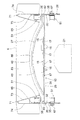
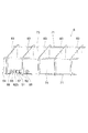
図12(a)及び(b)は、取付具51の拡大斜視図である。   12A and 12B are enlarged perspective views of the fixture 51. FIG.

取付具51は、光源モジュール12に対して固定されるガイド部材52と、ガイド部材52によってガイドされつつ、後述する保持位置と解除位置との間を移動する可動部材53とを有する。   The fixture 51 includes a guide member 52 fixed to the light source module 12 and a movable member 53 that moves between a holding position and a release position, which will be described later, while being guided by the guide member 52.

図12(a)は可動部材53が保持位置にある状態(保持状態)を、図12(b)は可動部材53が解除位置にある状態(解除状態)を表す。
図13(a)はガイド部材52の斜視図であり、図13(b)は可動部材53の斜視図である。
12A shows a state where the movable member 53 is in the holding position (holding state), and FIG. 12B shows a state where the movable member 53 is in the releasing position (released state).
FIG. 13A is a perspective view of the guide member 52, and FIG. 13B is a perspective view of the movable member 53.

ガイド部材52は、矩形板状のベース部54と、ベース部54の短手方向(幅方向)の両端にベース部54に対して直角な一対の側面部55及び56とが一体に設けられた金属材料からなる。   The guide member 52 is integrally formed with a rectangular plate-shaped base portion 54 and a pair of side surface portions 55 and 56 that are perpendicular to the base portion 54 at both ends in the short direction (width direction) of the base portion 54. Made of metal material.

一方の側面部55の長手方向の中央には開口57が形成されている。側面部55における開口57を長手方向に挟んだ一方の部分には1つの円形状の孔61と2つのスリット62a、62bが形成されている。側面部55における開口57を長手方向に挟んだ他方の部分にも1つの円形状の孔61と2つのスリット62a、62bが形成されている。2つのスリット62a、62bは、孔61と開口57との間に形成されている。孔61およびスリット62a、62bは、側面部55を貫通している。   An opening 57 is formed at the center in the longitudinal direction of one side surface portion 55. One circular hole 61 and two slits 62a and 62b are formed in one portion of the side surface portion 55 sandwiching the opening 57 in the longitudinal direction. One circular hole 61 and two slits 62a and 62b are also formed in the other portion of the side surface portion 55 with the opening 57 sandwiched in the longitudinal direction. The two slits 62 a and 62 b are formed between the hole 61 and the opening 57. The hole 61 and the slits 62 a and 62 b penetrate the side surface portion 55.

側面部55に対して平行に対向する側面部56における長手方向の中央部分には、開口57側に突出するガイドリブ58が側面部56に一体に設けられている。   A guide rib 58 that protrudes toward the opening 57 is provided integrally with the side surface portion 56 at a central portion in the longitudinal direction of the side surface portion 56 that faces the side surface portion 55 in parallel.

可動部材53は、矩形板状のベース部63と、係止部64と、板バネ部66とが一体に設けられた金属材料からなる。   The movable member 53 is made of a metal material in which a rectangular plate-like base portion 63, a locking portion 64, and a leaf spring portion 66 are integrally provided.

ベース部63には、その長手方向に沿ってガイド溝65が形成されている。ガイド溝65は、ベース部63を貫通している。   A guide groove 65 is formed in the base portion 63 along the longitudinal direction thereof. The guide groove 65 passes through the base portion 63.

ベース部63の長手方向の一方の端部(図13(b)において左端部)は、ベース部63に対して直角に図13(b)において紙面手前側に屈曲してからベース部63に対して平行に延在している。その屈曲部分よりも先端側にはT字状の係止部64が設けられている。   One end of the base portion 63 in the longitudinal direction (the left end portion in FIG. 13B) is bent at a right angle to the base portion 63 toward the front side of the page in FIG. Extending in parallel. A T-shaped locking portion 64 is provided on the tip side of the bent portion.

板バネ部66は、ベース部63の長手方向の他方の端部に対して、湾曲した部分を介して片持ち支持されつつ、ベース部63のガイド溝65に対向するように折り返されている。板バネ部66には、ベース部63から離れる方向(図13(b)において紙面手前側)に突出した操作部67が一体に設けられている。さらに、板バネ部66の先端には、操作部67と同じ方向に突出したロック部68が一体に設けられている。   The leaf spring portion 66 is folded back so as to face the guide groove 65 of the base portion 63 while being cantilevered via a curved portion with respect to the other end portion of the base portion 63 in the longitudinal direction. The leaf spring portion 66 is integrally provided with an operation portion 67 that protrudes in a direction away from the base portion 63 (the front side in FIG. 13B). Further, a locking portion 68 that protrudes in the same direction as the operation portion 67 is integrally provided at the tip of the leaf spring portion 66.

板バネ部66は、ベース部63との間の湾曲した部分を支点にして、ベース部63に対して近づく方向と遠ざかる方向とに揺動(傾動)可能となっている。   The leaf spring portion 66 can swing (tilt) in a direction toward and away from the base portion 63 with a curved portion between the leaf spring portion 66 and the base portion 63 as a fulcrum.

図12(a)に示すように、ガイド溝65内にガイドリブ58を差し込み、さらに開口57から操作部67を突出させた状態で、可動部材53のベース部63がガイド部材52の側面部56に重ね合わされ、可動部材53の板バネ部66がガイド部材52の側面部55に重ね合わされる。   As shown in FIG. 12A, the base portion 63 of the movable member 53 is connected to the side surface portion 56 of the guide member 52 with the guide rib 58 inserted into the guide groove 65 and the operation portion 67 protruding from the opening 57. The leaf spring portion 66 of the movable member 53 is overlaid on the side surface portion 55 of the guide member 52.

図12(a)の組み付け状態は、ガイド部材52のベース部54を底面とし、側面部55を紙面手前側に向けた姿勢で、開口57よりも左側に係止部64が位置し、開口57よりも左側の側面部55にロック部68が位置する組み付け状態を表す。図8に示す光源モジュール12の長手方向の左側の端部に取り付けられた取付具51における可動部材53は、図12(a)に示す向きでガイド部材52に組み付けられている。   The assembled state of FIG. 12A is such that the locking portion 64 is positioned on the left side of the opening 57 with the base portion 54 of the guide member 52 as the bottom surface and the side surface portion 55 facing toward the front side of the drawing. The assembled state in which the lock portion 68 is located on the left side surface portion 55 is shown. The movable member 53 in the fixture 51 attached to the left end in the longitudinal direction of the light source module 12 shown in FIG. 8 is assembled to the guide member 52 in the direction shown in FIG.

図12(a)において、可動部材53の上下を反転させて左右の向きを逆にし、係止部64及びロック部68を、開口57よりも右側に位置させて、可動部材53をガイド部材52に組み付けることも可能である。図8に示す光源モジュール12の長手方向の右側の端部に取り付けられた取付具51における可動部材53は、係止部64及びロック部68を、開口57よりも右側に位置させてガイド部材52に組み付けられている。   In FIG. 12A, the movable member 53 is turned upside down so that the left and right directions are reversed, the locking portion 64 and the lock portion 68 are positioned on the right side of the opening 57, and the movable member 53 is moved to the guide member 52. It is also possible to assemble to. The movable member 53 of the fixture 51 attached to the right end in the longitudinal direction of the light source module 12 shown in FIG. 8 has the locking portion 64 and the lock portion 68 positioned on the right side of the opening 57 to guide the member 52. It is assembled to.

すなわち、共通のガイド部材52及び可動部材53を使いつつ、ガイド部材52に対する可動部材53の取り付け向きを変えることで、光源モジュール12の長手方向の左右どちらの端部に取り付けても、係止片64を光源モジュール12の端部から突出させることができる。   That is, by using the common guide member 52 and the movable member 53 and changing the mounting direction of the movable member 53 with respect to the guide member 52, the locking piece can be attached to either the left or right end in the longitudinal direction of the light source module 12. 64 can protrude from the end of the light source module 12.

可動部材53がいずれの向きに取り付けられても、本体2に対する光源モジュール12の取付状態が保持される保持状態では、ロック部68は孔61に近い側のスリット62aに差し込まれ、本体2に対して光源モジュール12が離脱可能となる解除状態では、ロック部68は開口57に近い側のスリット62bに差し込まれる。   Regardless of the direction in which the movable member 53 is attached, in the holding state in which the attachment state of the light source module 12 with respect to the main body 2 is maintained, the lock portion 68 is inserted into the slit 62 a on the side close to the hole 61. In the released state where the light source module 12 can be detached, the lock portion 68 is inserted into the slit 62 b on the side close to the opening 57.

ガイド部材52に組み合わされた状態で、可動部材53のベース部63と板バネ部66との間の間隔は自然状態から若干縮められた状態となり、板バネ部66は自然状態への復元力により、ガイド部材52の側面部55側に付勢される。したがって、保持状態および解除状態のいずれでも、ロック部68がスリット62aまたは62bに差し込まれた状態が維持される。   When combined with the guide member 52, the distance between the base portion 63 and the leaf spring portion 66 of the movable member 53 is slightly reduced from the natural state, and the leaf spring portion 66 is restored by the restoring force to the natural state. The guide member 52 is biased toward the side surface portion 55 side. Therefore, the state in which the lock portion 68 is inserted into the slit 62a or 62b is maintained in both the holding state and the released state.

そして、例えば図12(a)に示す保持状態で、操作部67をベース部63側に押すとロック部68がスリット62aから抜け、可動部材53の右方へのスライドが可能となる。ロック部68を開口57側のスリット62bに対向する位置まで可動部材53を移動させ、操作部67への押圧力を解除すると、図12(b)に示すようにスリット62bにロック部68を差し込んで解除状態を維持することができる。   Then, for example, in the holding state shown in FIG. 12A, when the operating portion 67 is pushed to the base portion 63 side, the lock portion 68 comes out of the slit 62a, and the movable member 53 can be slid to the right. When the movable member 53 is moved to a position where the lock portion 68 faces the slit 62b on the opening 57 side and the pressing force to the operation portion 67 is released, the lock portion 68 is inserted into the slit 62b as shown in FIG. The release state can be maintained.

解除状態では、保持状態よりも可動部材53が右側に移動した分、ガイド部材52左端からの係止片64の突出長さが短くなっている。解除状態で、操作部67をベース部63側に押すとロック部68がスリット62bから抜け、図12(a)に示す保持位置まで、可動部材53を左方にスライドさせることができる。   In the released state, the protrusion length of the locking piece 64 from the left end of the guide member 52 is shortened by the amount of movement of the movable member 53 to the right than in the holding state. When the operating portion 67 is pushed to the base portion 63 side in the released state, the lock portion 68 comes out of the slit 62b, and the movable member 53 can be slid leftward to the holding position shown in FIG.

静止体であるガイド部材52のガイドリブ58に沿って、可動部材53のガイド溝65が相対的に移動することで、可動部材53の円滑且つ安定したスライド移動が実現される。   By moving the guide groove 65 of the movable member 53 relatively along the guide ribs 58 of the guide member 52 that is a stationary body, smooth and stable sliding movement of the movable member 53 is realized.

次に、バッフル部材6について説明する。   Next, the baffle member 6 will be described.

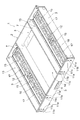
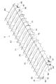
図15は、バッフル部材6の斜視図である。
図16は、バッフル部材6の長手方向の端部の拡大斜視図である。
図20は、一対のバッフル支持部71のうちの一方(図15における右側)のバッフル支持部71の底面側から見た拡大斜視図である。
FIG. 15 is a perspective view of the baffle member 6.
FIG. 16 is an enlarged perspective view of the end portion of the baffle member 6 in the longitudinal direction.
FIG. 20 is an enlarged perspective view of one of the pair of baffle support portions 71 (the right side in FIG. 15) as viewed from the bottom surface side of the baffle support portion 71.

バッフル部材6は、一対のバッフル支持部71と、バッフル支持部71に支持された複数の板状のバッフル83とを有する。複数のバッフル83が、バッフル支持部71の長手方向に互いに離間して並んでいる。   The baffle member 6 has a pair of baffle support portions 71 and a plurality of plate-like baffles 83 supported by the baffle support portions 71. A plurality of baffles 83 are arranged apart from each other in the longitudinal direction of the baffle support portion 71.

図17は、バッフル支持部71の斜視図である。
図18は、バッフル支持部71におけるスリット76及び77が形成された部分の拡大断面図である。
FIG. 17 is a perspective view of the baffle support portion 71.
FIG. 18 is an enlarged cross-sectional view of a portion of the baffle support portion 71 where the slits 76 and 77 are formed.

バッフル支持部71は、金属板(例えば鋼板)を曲げ加工することで、底面部72と、底面部72に対して垂直な垂直側面部74と、底面部72及び垂直側面部74に対して傾斜した傾斜側面部73とを有する、直角三角柱形状に形成されている。   The baffle support portion 71 is bent with respect to the bottom surface portion 72, the vertical side surface portion 74 perpendicular to the bottom surface portion 72, and the bottom surface portion 72 and the vertical side surface portion 74 by bending a metal plate (for example, a steel plate). It is formed in the shape of a right triangular prism having the inclined side surface portion 73.

底面部72は、図18に示すように、バッフル支持部71へと加工される金属板の短手方向(幅方向)の両端部72a及び72bが重ね合わさって構成され、底面部72には貫通孔78が形成されている。   As shown in FIG. 18, the bottom surface portion 72 is configured by overlapping both end portions 72 a and 72 b in the short direction (width direction) of the metal plate processed into the baffle support portion 71. A hole 78 is formed.

底面部72は矩形板状に形成され、その短手方向(幅方向)の一方の端部に垂直側面部74が一体に設けられ、他方の端部に傾斜側面部73が一体に設けられている。垂直側面部74と傾斜側面部73とは、湾曲した頂部75を介して一体につながっている。   The bottom surface portion 72 is formed in a rectangular plate shape, and a vertical side surface portion 74 is integrally provided at one end portion in the short side direction (width direction), and an inclined side surface portion 73 is integrally provided at the other end portion. Yes. The vertical side surface portion 74 and the inclined side surface portion 73 are integrally connected via a curved top portion 75.

傾斜側面部73及び垂直側面部74における頂部75側の上半分ほどにはスリット76が形成されている。複数のスリット76が、バッフル支持部71の長手方向に所定間隔で形成されている。   A slit 76 is formed in the upper half of the inclined side surface 73 and the vertical side surface 74 on the top 75 side. A plurality of slits 76 are formed at predetermined intervals in the longitudinal direction of the baffle support portion 71.

垂直側面部74においてそれぞれのスリット76の底面部72側の直下には、スリット76と同じ幅のスリット77が形成されている。したがって、複数のスリット77がバッフル支持部71の長手方向に所定間隔で形成されている。スリット77は、スリット76とはつながっておらず、また底面部72には達していない。   In the vertical side surface 74, a slit 77 having the same width as the slit 76 is formed immediately below the bottom surface 72 side of each slit 76. Therefore, a plurality of slits 77 are formed at predetermined intervals in the longitudinal direction of the baffle support portion 71. The slit 77 is not connected to the slit 76 and does not reach the bottom surface portion 72.

垂直側面部74の長手方向の両端部のそれぞれには、一対の円形状の孔81と、1つの矩形状の開口82とが、ともに垂直側面部74を貫通して形成されている。一対の孔81は、開口82を長手方向に挟んだ位置に形成されている。   A pair of circular holes 81 and one rectangular opening 82 are both formed through the vertical side surface 74 at both ends in the longitudinal direction of the vertical side surface 74. The pair of holes 81 are formed at positions sandwiching the opening 82 in the longitudinal direction.

バッフル支持部71の内側の空間の幅は、底面部72から頂部75に向かうにしたがって狭められている。   The width of the space inside the baffle support portion 71 is narrowed from the bottom surface portion 72 toward the top portion 75.

次に、図19は、バッフル83の拡大斜視図である。   Next, FIG. 19 is an enlarged perspective view of the baffle 83.

バッフル83には一対の切欠き84が形成されている。それぞれの切欠き84の内壁にはツメ部85が設けられている。一対の切欠き84及びツメ部85は、バッフル83の長手方向を2等分する中心線に対して対称的に形成されている。   A pair of notches 84 are formed in the baffle 83. A claw portion 85 is provided on the inner wall of each notch 84. The pair of notches 84 and claw portions 85 are formed symmetrically with respect to a center line that bisects the longitudinal direction of the baffle 83.

切欠き84が開口されている側の端部(図19における下端部)は、光源モジュール12側に向けられ、その端部における一対の切欠き84の間の部分は、光源モジュール12のカバー27の曲面部41に沿った曲面部86となっている。   An end portion on the side where the notch 84 is opened (lower end portion in FIG. 19) is directed toward the light source module 12, and a portion between the pair of notches 84 at the end portion is the cover 27 of the light source module 12. It is a curved surface portion 86 along the curved surface portion 41.

図15に示すように、一対のバッフル支持部71が、互いの傾斜側面部73を対向させて平行に配置される。一対のバッフル支持部71は、バッフル83に形成された一対の切欠き84間の距離に応じた距離を隔てて平行に配置される。   As shown in FIG. 15, the pair of baffle support portions 71 are arranged in parallel with the inclined side surface portions 73 facing each other. The pair of baffle support portions 71 are arranged in parallel with a distance corresponding to the distance between the pair of notches 84 formed in the baffle 83.

そして、一方のバッフル支持部71のスリット76にバッフル83の一方の切欠き84を差し込み、他方のバッフル支持部71のスリット76にバッフル83の他方の切欠き84を差し込む。バッフル83は、切欠き84の上壁84aがスリット76の下端に当接する位置まで差し込まれる。   Then, one notch 84 of the baffle 83 is inserted into the slit 76 of one baffle support portion 71, and the other notch 84 of the baffle 83 is inserted into the slit 76 of the other baffle support portion 71. The baffle 83 is inserted to a position where the upper wall 84 a of the notch 84 comes into contact with the lower end of the slit 76.

その状態で、切欠き84の内壁に設けられたツメ部85が、図20に示すように、垂直側面部74に形成されたスリット77に差し込まれる。ツメ部85の上端がスリット77の上端に当接することで、バッフル支持部71からのバッフル83の脱落が防止される。   In this state, the claw portion 85 provided on the inner wall of the notch 84 is inserted into the slit 77 formed in the vertical side surface portion 74 as shown in FIG. Since the upper end of the claw portion 85 contacts the upper end of the slit 77, the baffle 83 is prevented from falling off from the baffle support portion 71.

また、バッフル支持部71の底面部72に形成された貫通孔78には、図20に示すリベット87が差し込まれカシメられる。これにより、傾斜側面部73と垂直側面部74とがなす角度が小さくなる方向への傾斜側面部73及び垂直側面部74の移動が規制される。したがって、ツメ部85がスリット77から抜けることがなく、バッフル83のバッフル支持部71からの離脱を防ぐことができる。   Further, a rivet 87 shown in FIG. 20 is inserted into the through-hole 78 formed in the bottom surface portion 72 of the baffle support portion 71 and crimped. Thereby, the movement of the inclined side surface portion 73 and the vertical side surface portion 74 in the direction in which the angle formed by the inclined side surface portion 73 and the vertical side surface portion 74 becomes smaller is restricted. Therefore, the claw portion 85 does not come out of the slit 77, and the baffle 83 can be prevented from being detached from the baffle support portion 71.

前述した光源モジュール12及びバッフル部材6は、それぞれ、取付具51を介して本体2に対して着脱自在に取り付けられる。   The light source module 12 and the baffle member 6 described above are detachably attached to the main body 2 via the attachment 51, respectively.

光源モジュール12の長手方向の端部には、図8に示すように、前述した取付具51が取り付けられている。取付具51は、放熱板25の側面部32の内側に位置する。取付具51のガイド部材52に形成された図12(a)に示す孔61が、図11に示す側面部32に形成された孔33及び側面部32に重ね合わされる取付部材26の側板部35に形成された孔37に一致され、それら孔37、33及び61に、図8に示すリベット45が差し込まれてカシメられる。これにより、取付具51のガイド部材52が光源モジュール12の側板部35に対して固定される。   As shown in FIG. 8, the fixture 51 described above is attached to the end of the light source module 12 in the longitudinal direction. The fixture 51 is located inside the side surface portion 32 of the heat radiating plate 25. The hole 61 shown in FIG. 12A formed in the guide member 52 of the fixture 51 is overlapped with the hole 33 formed in the side surface portion 32 shown in FIG. 11 and the side surface portion 32. The rivets 45 shown in FIG. 8 are inserted into the holes 37, 33, and 61 and crimped. Thereby, the guide member 52 of the fixture 51 is fixed to the side plate portion 35 of the light source module 12.

取付具51の可動部材53の操作部67は、図11に示す側面部32の開口34及びこれに重ねられた側板部35の開口38から側板部35の外側に突出する。操作部67は、前述したように板バネ部66に設けられおり、操作部67を側板部35の内側に押しつつ、横方向(側板部35の長手方向)にスライドさせることができる。   The operating portion 67 of the movable member 53 of the fixture 51 protrudes to the outside of the side plate portion 35 from the opening 34 of the side surface portion 32 and the opening 38 of the side plate portion 35 overlapped thereon as shown in FIG. As described above, the operation portion 67 is provided on the leaf spring portion 66, and can be slid in the lateral direction (longitudinal direction of the side plate portion 35) while pushing the operation portion 67 inward of the side plate portion 35.

操作部67のスライドにともない係止部64も横方向(側板部35の長手方向)にスライドする。可動部材53が図12(a)及び図14(a)に示す保持位置にあるとき、係止部64は、側板部35の端部から突出している。   As the operation portion 67 slides, the locking portion 64 also slides in the lateral direction (longitudinal direction of the side plate portion 35). When the movable member 53 is in the holding position shown in FIGS. 12A and 14A, the locking portion 64 protrudes from the end portion of the side plate portion 35.

可動部材53が図12(b)及び図14(b)に示す解除位置にあるとき、側板部35の端部からの係止部64の突出長さは、上記保持位置にあるときよりも短い。図14(b)に示す例では、解除位置で係止部64は側板部35の端部から突出せずに、側板部35の内側に隠れてしまっているが、保持位置よりも相対的に解除位置で係止部64の突出長さが短ければよく、解除位置で係止部64が側板部35の端部から少し突出していてもよい。   When the movable member 53 is in the release position shown in FIGS. 12B and 14B, the protruding length of the locking portion 64 from the end portion of the side plate portion 35 is shorter than that in the holding position. . In the example shown in FIG. 14B, the locking portion 64 does not protrude from the end portion of the side plate portion 35 at the release position, but is hidden inside the side plate portion 35, but is relatively relative to the holding position. The protruding length of the locking portion 64 may be short at the release position, and the locking portion 64 may slightly protrude from the end of the side plate portion 35 at the release position.

図3に示すように、光源モジュール12は本体2の光源収納部13内に、発光素子17が搭載された発光面を、天井面とは反対側(図3において上側)に向けて収納される。光源モジュール12が光源収納部13内に収納された状態で、取付具51は図12(a)及び図14(a)に示す保持位置をとり、図6に示すように、係止部64が本体2の外枠3に形成された係止孔11bに係止している。すなわち、係止部64が係止孔11bから外枠3の外側に突き出て、係止部64の下端部が係止孔11bの下端部に当接することで、光源モジュール12の本体2からの脱落が防止されている。   As shown in FIG. 3, the light source module 12 is stored in the light source storage section 13 of the main body 2 with the light emitting surface on which the light emitting element 17 is mounted facing away from the ceiling surface (upper side in FIG. 3). . In a state where the light source module 12 is housed in the light source housing section 13, the fixture 51 takes the holding position shown in FIGS. 12 (a) and 14 (a). As shown in FIG. The main body 2 is locked in a locking hole 11 b formed in the outer frame 3. That is, the locking portion 64 protrudes from the locking hole 11b to the outside of the outer frame 3, and the lower end portion of the locking portion 64 comes into contact with the lower end portion of the locking hole 11b. Dropping is prevented.

取付具51が保持位置にあるとき、図12(a)に示すように、ロック部68がスリット62aに差し込まれている。そして、前述したように、板バネ部66の付勢力によりロック部68がスリット62aに差し込まれた状態が維持される。これにより、振動や衝撃などで可動部材53が解除位置へと移動してしまうことを防ぐことができ、本体2に対して光源モジュール12が取り付けられた状態を安定して維持することができる。   When the fixture 51 is in the holding position, the lock portion 68 is inserted into the slit 62a as shown in FIG. As described above, the state in which the lock portion 68 is inserted into the slit 62a by the urging force of the leaf spring portion 66 is maintained. Thereby, it can prevent that the movable member 53 moves to a cancellation | release position by a vibration, an impact, etc., and the state where the light source module 12 was attached with respect to the main body 2 can be maintained stably.

前述したように、操作部67を押すことでロック部68をスリット62a抜くことができ、可動部材53を、図12(b)及び図14(b)に示す解除位置へとスライドさせることができる。解除位置では、係止部64が係止孔11bから抜け、光源モジュール12を本体2から取り外すことができる。   As described above, by pushing the operating portion 67, the lock portion 68 can be removed from the slit 62a, and the movable member 53 can be slid to the release position shown in FIGS. 12 (b) and 14 (b). . In the release position, the locking portion 64 can be removed from the locking hole 11 b and the light source module 12 can be removed from the main body 2.

あるいは、光源モジュール12を本体2に対して取り付けるにあたって、係止部64を解除位置に引っ込めておくことで、係止部64が外枠2にぶつからず、光源モジュール12を光源収納部13内に円滑に収納することができる。そして、光源モジュール12が光源収納部13内に収納された後、操作部67を解除位置から保持位置へとスライドさせることで、係止部64を係止孔11bに引っ掛けることができる。   Alternatively, when the light source module 12 is attached to the main body 2, the locking portion 64 is retracted to the release position, so that the locking portion 64 does not hit the outer frame 2 and the light source module 12 is placed in the light source storage portion 13. It can be stored smoothly. And after the light source module 12 is accommodated in the light source accommodating part 13, the latching | locking part 64 can be hooked in the latching hole 11b by sliding the operation part 67 from a release position to a holding position.

解除位置においても、図12(b)に示すように、ロック部68がスリット62bに差し込まれた状態が板バネ部66の付勢力により安定して維持することができ、着脱作業を安定して行うことができる。そして、操作部67を押すことでロック部68をスリット62bから抜くことができ、係止部64を保持位置までスライドさせることができる。   Even in the release position, as shown in FIG. 12B, the state in which the lock portion 68 is inserted into the slit 62b can be stably maintained by the urging force of the leaf spring portion 66, and the attachment / detachment operation can be stably performed. It can be carried out. Then, by pressing the operating portion 67, the lock portion 68 can be pulled out from the slit 62b, and the locking portion 64 can be slid to the holding position.

図4に示すように、光源モジュール12が光源収納部13内に収納された状態で、光源モジュール12の側板部35は、光源収納枠を構成する外枠3及び内枠7の内壁との間に隙間18を隔てて、外枠3及び内枠7の内壁に対向する。   As shown in FIG. 4, in a state where the light source module 12 is housed in the light source housing portion 13, the side plate portion 35 of the light source module 12 is between the outer frame 3 constituting the light source housing frame and the inner wall of the inner frame 7. The inner wall of the outer frame 3 and the inner frame 7 is opposed to each other with a gap 18 therebetween.

取付具51の操作部67は、隙間18に突出して露出する。隙間18の幅は人の指が入る大きさであり、その隙間18に指を入れて操作部67に触れて、操作部67を側板部35の内側に押し込みつつ、横方向にスライドさせることができる。あるいは、操作部67を指で直接操作することに限らず、治具を使って操作してもよい。また、隙間18は、空調設備の吸気口としても機能する。   The operation part 67 of the fixture 51 is exposed to protrude into the gap 18. The width of the gap 18 is large enough to allow a human finger to enter, and the finger can be inserted into the gap 18 to touch the operation unit 67, and the operation unit 67 can be slid laterally while being pushed into the side plate portion 35. it can. Or you may operate using the jig | tool not only directly operating the operation part 67 with a finger | toe. The gap 18 also functions as an air inlet for the air conditioning equipment.

また、操作部67は、光源モジュール12における発光面とは反対側に突出した側板部35の横に露出され、発光面を遮光せず、配光特性に影響を与えず、また使用者からも見えにくい位置にあり、外観意匠性を損ねない。   Further, the operation unit 67 is exposed to the side of the side plate portion 35 protruding to the opposite side of the light emitting surface in the light source module 12, does not shield the light emitting surface, does not affect the light distribution characteristics, and is also from the user. It is in a position that is difficult to see and does not impair the appearance design.

図2に示すように、バッフル部材6は、光源収納部13内における光源モジュール12の発光面側に収納される。したがって、照明器具1の真下以外の下方空間にいる使用者が照明器具1を特定角度から見上げた際に、バッフル83によって発光面が遮られ、発光面を直接視認することがなく、まぶしさ感を軽減できる。   As shown in FIG. 2, the baffle member 6 is housed on the light emitting surface side of the light source module 12 in the light source housing section 13. Therefore, when a user in a lower space other than directly under the lighting fixture 1 looks up at the lighting fixture 1 from a specific angle, the light emitting surface is blocked by the baffle 83, and the light emitting surface is not directly seen, so that the user feels glare. Can be reduced.

バッフル部材6にも、図15及び図16に示すように、光源モジュール12に取り付けられた取付具51と同じ構成の取付具51が取り付けられている。   As shown in FIGS. 15 and 16, the baffle member 6 is also attached with a fixture 51 having the same configuration as the fixture 51 attached to the light source module 12.

取付具51は、バッフル支持部71の長手方向の端部に取り付けられている。取付具51は、バッフル支持部71における底面部72と垂直側面部74と傾斜側面部73とで囲まれた空間内に配置されている。   The fixture 51 is attached to the end of the baffle support 71 in the longitudinal direction. The fixture 51 is disposed in a space surrounded by the bottom surface portion 72, the vertical side surface portion 74, and the inclined side surface portion 73 in the baffle support portion 71.

取付具51のガイド部材52に形成された図12(a)に示す孔61が、図17に示す垂直側面部74に形成された孔81に一致され、それら孔81及び61に、図16に示すリベット88が差し込まれてカシメられる。これにより、取付具51のガイド部材52がバッフル支持部71の垂直側面部74に対して固定される。   A hole 61 shown in FIG. 12A formed in the guide member 52 of the fixture 51 is matched with a hole 81 formed in the vertical side surface 74 shown in FIG. 17, and these holes 81 and 61 are shown in FIG. The rivet 88 shown is inserted and crimped. Thereby, the guide member 52 of the fixture 51 is fixed to the vertical side surface portion 74 of the baffle support portion 71.

そして、光源モジュール12と同様に、バッフル部材6が光源収納部13内に収納された状態で、取付具51は図12(a)に示す保持位置をとる。その保持状態で、図6に示すように、バッフル部材6に取り付けられた取付具51の係止部64は、本体2の外枠3に形成された係止孔11aに係止している。すなわち、係止部64が係止孔11aから外枠3の外側に突き出て、係止部64の下端部が係止孔11aの下端部に当接することで、バッフル部材6の本体2からの脱落が防止されている。   Then, like the light source module 12, the fixture 51 takes the holding position shown in FIG. 12A in a state where the baffle member 6 is stored in the light source storage unit 13. In the held state, as shown in FIG. 6, the locking portion 64 of the fixture 51 attached to the baffle member 6 is locked in the locking hole 11 a formed in the outer frame 3 of the main body 2. That is, the locking portion 64 protrudes from the locking hole 11a to the outside of the outer frame 3, and the lower end portion of the locking portion 64 comes into contact with the lower end portion of the locking hole 11a. Dropping is prevented.

光源モジュール12と同様に、板バネ部66の付勢力によりロック部68がスリット62aに差し込まれた状態が維持され、振動や衝撃などで可動部材53が解除位置へと移動してしまうことを防ぐことができる。したがって、本体2に対してバッフル部材6が取り付けられた状態を安定して維持することができる。   Similarly to the light source module 12, the state in which the lock portion 68 is inserted into the slit 62a is maintained by the urging force of the leaf spring portion 66, and the movable member 53 is prevented from moving to the release position due to vibration or impact. be able to. Therefore, the state where the baffle member 6 is attached to the main body 2 can be stably maintained.

また、操作部67を押すことでロック部68をスリット62a抜くことができ、可動部材53を、図12(b)に示す解除位置へとスライドさせることができる。解除位置では、係止部64が係止孔11aから抜け、バッフル部材6を本体2から取り外すことができる。   Further, by pushing the operating portion 67, the lock portion 68 can be removed from the slit 62a, and the movable member 53 can be slid to the release position shown in FIG. In the release position, the locking portion 64 can be removed from the locking hole 11 a and the baffle member 6 can be removed from the main body 2.

あるいは、バッフル部材6を本体2に取り付けるにあたって、係止部64を解除位置に引っ込めておくことで、係止部64が外枠2にぶつからず、バッフル部材6を光源収納部13内に円滑に収納することができる。そして、バッフル部材6が光源収納部13内に収納された後、操作部67を解除位置から保持位置へとスライドさせることで、係止部64を係止孔11aに引っ掛けることができる。   Alternatively, when the baffle member 6 is attached to the main body 2, the locking portion 64 is retracted to the release position, so that the locking portion 64 does not hit the outer frame 2 and the baffle member 6 is smoothly placed in the light source storage portion 13. Can be stored. And after the baffle member 6 is accommodated in the light source accommodating part 13, the engaging part 64 can be hooked in the engaging hole 11a by sliding the operating part 67 from the release position to the holding position.

操作部67は、図17に示すバッフル支持部71の垂直側面部74に形成された開口82から垂直側面部74の外側に突出する。図15及び16に示すように、バッフル83の両端部は、バッフル支持部71よりも外側(垂直側面部74の外側)に突出している。操作部67は、そのバッフル83の突出した部分の間で露出している。   The operation part 67 projects to the outside of the vertical side surface part 74 from an opening 82 formed in the vertical side surface part 74 of the baffle support part 71 shown in FIG. As shown in FIGS. 15 and 16, both end portions of the baffle 83 protrude outward from the baffle support portion 71 (outside of the vertical side surface portion 74). The operation part 67 is exposed between the protruding parts of the baffle 83.

バッフル83の端部が垂直側面部74よりも突出していることで、バッフル部材6が光源収納部13に収納された状態で、垂直側面部74と外枠3との間、および垂直側面部74と内枠7との間には隙間が形成される。その隙間におけるさらにバッフル83の端部で仕切られた空間に指を入れて操作部67を操作することができる。あるいは、操作部67を指で直接操作することに限らず、治具を使って操作してもよい。   Since the end portion of the baffle 83 protrudes from the vertical side surface portion 74, the baffle member 6 is stored in the light source storage portion 13, and between the vertical side surface portion 74 and the outer frame 3, and the vertical side surface portion 74. A gap is formed between the inner frame 7 and the inner frame 7. The operation unit 67 can be operated by putting a finger into a space further partitioned by the end of the baffle 83 in the gap. Or you may operate using the jig | tool not only directly operating the operation part 67 with a finger | toe.

以上説明した実施形態の照明器具1によれば、光源モジュール12及びバッフル部材6は、本体2に対して取付具51を介して着脱自在に取り付けられている。したがって、操作部67を操作することで、光源モジュール12及びバッフル部材6を本体2に対して容易に着脱することができる。   According to the lighting fixture 1 of the embodiment described above, the light source module 12 and the baffle member 6 are detachably attached to the main body 2 via the fixture 51. Therefore, the light source module 12 and the baffle member 6 can be easily attached to and detached from the main body 2 by operating the operation unit 67.

図6に示すように、外枠3には高さの異なる位置に複数の係止孔11a〜11cが形成されている。そして、係止部64を係止させる係止孔11a〜11cを選択することで、光源モジュール12やバッフル部材6の光源収納部13内での取り付け高さを変えることができる。   As shown in FIG. 6, the outer frame 3 is formed with a plurality of locking holes 11a to 11c at different heights. And the attachment height in the light source storage part 13 of the light source module 12 or the baffle member 6 can be changed by selecting the locking holes 11a-11c which lock the locking part 64. FIG.

例えば、使用者の要求に応じて、バッフル部材6を取り付けないこともできる。この場合、図7に示すように、光源モジュール12に取り付けられた取付具51の係止部64を、3対の係止孔11a〜11cの中で真ん中の高さの位置に形成された係止孔11bに係止させることで、天井側の係止孔11aに係止部64を係止させる場合に比べて、発光面をより下方(照明対象空間)側に近づけることができる。あるいは、光源モジュール12の係止部64を、天井から最も遠い係止孔11cに係止させてもよい。   For example, the baffle member 6 may not be attached according to the user's request. In this case, as shown in FIG. 7, the engaging portion 64 of the fixture 51 attached to the light source module 12 is formed at a middle height position in the three pairs of engaging holes 11 a to 11 c. By engaging with the stop hole 11b, the light emitting surface can be brought closer to the lower side (illumination target space) as compared to the case where the engagement portion 64 is engaged with the engagement hole 11a on the ceiling side. Alternatively, the locking portion 64 of the light source module 12 may be locked in the locking hole 11c farthest from the ceiling.

バッフル部材6を取り付ける場合には、図1、2及び6を参照して前述した実施形態のように、光源モジュール12の係止部64を天井側の係止孔11aに係止させ、バッフル部材6の係止部64を係止孔11aの下方の係止孔11bに係止させることで、バッフル部材6が本体2の下面側に大きく突出することによる光学特性や見栄えの悪化を防ぐことができる。   When the baffle member 6 is attached, the locking portion 64 of the light source module 12 is locked in the locking hole 11a on the ceiling side as in the embodiment described above with reference to FIGS. By locking the 6 locking portions 64 in the locking holes 11 b below the locking holes 11 a, it is possible to prevent deterioration of optical characteristics and appearance due to the baffle member 6 projecting greatly toward the lower surface side of the main body 2. it can.

また、光源モジュール12とバッフル部材6とを、同じ共通部品である取付具51を使って本体2に着脱できる。このため、光源モジュール12を本体2に取り付けるときと、バッフル部材6を本体2に取り付けるときとで、取付具51の操作が同じであり、設置者の作業性を向上できる。さらに、部品共通化によるコスト低減も図れる。   Further, the light source module 12 and the baffle member 6 can be attached to and detached from the main body 2 using the fixture 51 that is the same common component. For this reason, when the light source module 12 is attached to the main body 2 and when the baffle member 6 is attached to the main body 2, the operation of the fixture 51 is the same, and the workability of the installer can be improved. In addition, cost reduction can be achieved by sharing parts.

図5は、光源収納部13内における、光源モジュール12とバッフル部材6との配置関係を表す。   FIG. 5 shows an arrangement relationship between the light source module 12 and the baffle member 6 in the light source storage unit 13.

また、光源モジュール12の裏側(天井側)には、発光素子17に電力を供給し、発光素子17の点灯を制御する電源ユニット(もしくは制御ユニット)21が配置されている。   A power supply unit (or control unit) 21 that supplies power to the light emitting element 17 and controls lighting of the light emitting element 17 is disposed on the back side (ceiling side) of the light source module 12.

バッフル部材6のバッフル支持部71及びその内部空間に配置された取付具51は、光源モジュール12における光源ユニット15が搭載された発光面よりも短手方向の外側に位置している。このため、バッフル支持部71及び取付具51は、発光面から放出される光の妨げにならない。   The baffle support portion 71 of the baffle member 6 and the fixture 51 disposed in the internal space thereof are located on the outer side in the lateral direction from the light emitting surface on which the light source unit 15 in the light source module 12 is mounted. For this reason, the baffle support part 71 and the fixture 51 do not interfere with the light emitted from the light emitting surface.

また、図5において上側に位置することになる使用者から見て、バッフル部材6の取付具51はバッフル支持部71の内部に隠れており、光源モジュール12の取付具51は、発光面よりも短手方向の外側の裏側に隠れているため、取付具51は使用者からは見えず、外観意匠性を損ねない。   In addition, when viewed from the user who is positioned on the upper side in FIG. 5, the fixture 51 of the baffle member 6 is hidden inside the baffle support portion 71, and the fixture 51 of the light source module 12 is more than the light emitting surface. Since it is hidden behind the outer side in the short direction, the fixture 51 is not visible to the user and does not impair the appearance design.

図5において発光面の上方(天井から見ると下方)の空間の側部には、光源モジュール12の長手方向(紙面を貫く方向)に沿ってバッフル支持部71の傾斜側面部73が延在している。これにより、発光面側から使用者のいる空間に向かって広がる配光を実現できる。   In FIG. 5, the inclined side surface portion 73 of the baffle support portion 71 extends along the longitudinal direction of the light source module 12 (direction passing through the paper surface) in the side portion of the space above the light emitting surface (downward when viewed from the ceiling). ing. Thereby, the light distribution which spreads toward the space where a user exists from the light emission surface side is realizable.

バッフル83の光源モジュール12側の端部の曲面部86と、光源モジュール12のカバー27の曲面部41との間には隙間46が形成され、バッフル83はカバー27に接触していない。このため、カバー27の損傷を防ぐことができる。   A gap 46 is formed between the curved surface portion 86 at the end of the baffle 83 on the light source module 12 side and the curved surface portion 41 of the cover 27 of the light source module 12, and the baffle 83 is not in contact with the cover 27. For this reason, damage to the cover 27 can be prevented.

また、バッフル83の曲面部86をカバー27の曲面部41に合わせた形状にすることで、それらの間の隙間46の高さを均一にすることができる。これにより、カバー27の曲面部41の形状によって制御される配光特性が隙間46の存在によって損なわれない。   Further, by making the curved surface portion 86 of the baffle 83 match the curved surface portion 41 of the cover 27, the height of the gap 46 between them can be made uniform. Thereby, the light distribution characteristic controlled by the shape of the curved surface portion 41 of the cover 27 is not impaired by the presence of the gap 46.

また、比較例として、1枚の板金における複数箇所を折り曲げてバッフルを立ち上げ、支持部とバッフルとが一体に設けられたバッフル部材の構造が考えられるが、これは重さの増大をまねく。   In addition, as a comparative example, a structure of a baffle member in which a plurality of locations on one sheet metal are bent to raise the baffle and the support portion and the baffle are integrally provided can be considered, but this leads to an increase in weight.

これに対して実施形態によれば、別体のバッフル支持部71とバッフル83とを組み合わせてバッフル部材6を形成している。バッフル支持部71を例えば鋼板から形成して強度を確保しつつ、バッフル83は例えばアルミニウム等から形成することで軽量化を図ることができる。   On the other hand, according to the embodiment, the baffle member 6 is formed by combining the separate baffle support portion 71 and the baffle 83. The baffle support portion 71 is formed of, for example, a steel plate to ensure strength, while the baffle 83 is formed of, for example, aluminum, so that the weight can be reduced.

また、本体2に取り付けられた状態で、バッフル支持部71において使用者から見えるのは傾斜側面部73及び垂直側面部74の外側の面だけであり、内側の面(内部空間の内壁面)は見えない。したがって、バッフル支持部71へと曲げ加工する前の板金において、上記外側の面になる一方の面だけ塗装(例えば白色に塗装)し、上記内側の面になる他方の面は塗装しなくてもよく、外観意匠性を損ねずに、塗装費用の低減によるコスト低減を図れる。   Moreover, in the state attached to the main body 2, only the outer side surfaces of the inclined side surface portion 73 and the vertical side surface portion 74 are visible to the user in the baffle support portion 71, and the inner surface (inner wall surface of the internal space) is can not see. Therefore, in the sheet metal before bending to the baffle support portion 71, only one surface that is the outer surface is painted (for example, painted white), and the other surface that is the inner surface is not painted. The cost can be reduced by reducing the coating cost without deteriorating the appearance design.

また、バッフル支持部71に形成する複数のスリット76の長手方向のピッチを変えることで、そのスリット76に差し込まれるバッフル83間のピッチを変えることができ、容易に遮光角度の制御が行える。複数のバッフル83は同じ構造の共通品を使える。   Further, by changing the longitudinal pitch of the plurality of slits 76 formed in the baffle support portion 71, the pitch between the baffles 83 inserted into the slits 76 can be changed, and the light shielding angle can be easily controlled. A plurality of baffles 83 can use a common product having the same structure.

本発明のいくつかの実施形態を説明したが、これらの実施形態は、例として提示したものであり、発明の範囲を限定することは意図していない。これら新規な実施形態は、その他の様々な形態で実施されることが可能であり、発明の要旨を逸脱しない範囲で、種々の省略、置き換え、変更を行うことができる。これら実施形態やその変形は、発明の範囲や要旨に含まれるとともに、特許請求の範囲に記載された発明とその均等の範囲に含まれる。   Although several embodiments of the present invention have been described, these embodiments are presented by way of example and are not intended to limit the scope of the invention. These novel embodiments can be implemented in various other forms, and various omissions, replacements, and changes can be made without departing from the scope of the invention. These embodiments and modifications thereof are included in the scope and gist of the invention, and are included in the invention described in the claims and the equivalents thereof.

1…照明器具、2…本体、3…外枠、5…設備プレート、6…バッフル部材、7…内枠、11a〜11c…係止孔、12…光源モジュール、13…光源収納部、15…光源ユニット、16…基板、17…発光素子、18…隙間、21…電源ユニット、25…放熱板、26…取付部材、27…カバー、35…側板部、51…取付具、52…ガイド部材、53…可動部材、64…係止部、66…板バネ部、67…操作部、68…ロック部、71…バッフル支持部、72…底面部、73…傾斜側面部、74…垂直側面部、76…スリット、83…バッフル、85…ツメ部   DESCRIPTION OF SYMBOLS 1 ... Lighting fixture, 2 ... Main body, 3 ... Outer frame, 5 ... Equipment plate, 6 ... Baffle member, 7 ... Inner frame, 11a-11c ... Locking hole, 12 ... Light source module, 13 ... Light source storage part, 15 ... Light source unit, 16 ... substrate, 17 ... light emitting element, 18 ... gap, 21 ... power supply unit, 25 ... heat sink, 26 ... mounting member, 27 ... cover, 35 ... side plate part, 51 ... fixture, 52 ... guide member, 53 ... movable member, 64 ... locking part, 66 ... leaf spring part, 67 ... operation part, 68 ... lock part, 71 ... baffle support part, 72 ... bottom part, 73 ... inclined side part, 74 ... vertical side part, 76 ... slit, 83 ... baffle, 85 ... claw

Claims (6)

光源収納枠を有する本体と、
前記光源収納枠の内側に設けられ、基板と前記基板上に搭載された発光素子とを有する光源モジュールと、
前記光源モジュールに取り付けられた取付具であって、前記光源モジュールの端部から突出して前記光源収納枠に係止して前記光源モジュールを前記本体に対して保持させる保持位置と、前記光源収納枠との係止が解除され前記光源モジュールを前記本体に対して離脱可能にする解除位置との間を移動自在な係止部を有する取付具と、
を備えた照明器具。
A main body having a light source storage frame;
A light source module provided inside the light source storage frame and having a substrate and a light emitting element mounted on the substrate;
A fixture attached to the light source module, the holding position projecting from an end of the light source module and engaging with the light source storage frame to hold the light source module with respect to the main body; and the light source storage frame A fixture having a locking portion that is movable between a release position that is released from the locking position and that allows the light source module to be detached from the main body;
Lighting equipment with
前記光源収納枠は、高さの異なる位置に形成され、前記係止部が係止可能な複数の係止孔を有し、
前記係止部を係止させる前記係止孔を選択することで、前記光源モジュールの前記光源収納枠内での取り付け高さを変える請求項1記載の照明器具。
The light source storage frame is formed at different heights, and has a plurality of locking holes in which the locking portion can be locked,
The lighting fixture according to claim 1, wherein the mounting height of the light source module in the light source storage frame is changed by selecting the locking hole for locking the locking portion.
前記取付具は板バネ部を含み、前記板バネ部の付勢力により、前記係止部の前記保持位置が維持される請求項1または2に記載の照明器具。   The lighting fixture according to claim 1, wherein the fixture includes a leaf spring portion, and the holding position of the locking portion is maintained by an urging force of the leaf spring portion. 前記光源モジュールは、前記基板における前記発光素子の搭載面とは反対側の裏面側に突出し、前記光源収納枠の内壁との間に隙間を隔てて前記内壁に対向する側板部を有し、
前記取付具は、前記隙間に突出しつつ、前記係止部と一体となってスライド自在に前記側板部に取り付けられた操作部を有する請求項1〜3のいずれか1つに記載の照明器具。
The light source module has a side plate portion that protrudes from the back surface side of the substrate opposite to the mounting surface of the light emitting element and faces the inner wall with a gap between the light source housing frame and the inner wall.
The lighting fixture according to any one of claims 1 to 3, wherein the fixture includes an operation portion that is slidably attached to the side plate portion integrally with the locking portion while projecting into the gap.
前記光源収納枠の内側における前記光源モジュールの発光面側に設けられたバッフル部材をさらに備え、
前記バッフル部材は、
複数のスリットを有するバッフル支持部と、
前記バッフル支持部の前記スリットに差し込まれ、前記光源モジュールの長手方向に互いに離間して並んだ複数の板状のバッフルと、
を有する請求項1〜4のいずれか1つに記載の照明器具。
Further comprising a baffle member provided on the light emitting surface side of the light source module inside the light source storage frame,
The baffle member is
A baffle support having a plurality of slits;
A plurality of plate-like baffles that are inserted into the slits of the baffle support portion and are spaced apart from each other in the longitudinal direction of the light source module;
The lighting fixture according to any one of claims 1 to 4.
前記バッフル部材にも、前記光源モジュールに取り付けられた前記取付具と同じ構造の取付具が取り付けられ、
前記バッフル部材も、前記取付具の前記係止部の移動操作により、前記本体に対して着脱自在である請求項5記載の照明器具。
A fixture having the same structure as the fixture attached to the light source module is also attached to the baffle member,
The lighting apparatus according to claim 5, wherein the baffle member is also detachable from the main body by an operation of moving the locking portion of the fixture.
JP2012043003A 2012-02-29 2012-02-29 Lighting fixture Pending JP2013179003A (en)

Priority Applications (4)

Application Number Priority Date Filing Date Title
JP2012043003A JP2013179003A (en) 2012-02-29 2012-02-29 Lighting fixture
EP13156785.1A EP2634475A1 (en) 2012-02-29 2013-02-26 Luminaire
CN2013100646565A CN103292230A (en) 2012-02-29 2013-02-28 Luminaire
US13/779,806 US20130223067A1 (en) 2012-02-29 2013-02-28 Luminaire

Applications Claiming Priority (1)

Application Number Priority Date Filing Date Title
JP2012043003A JP2013179003A (en) 2012-02-29 2012-02-29 Lighting fixture

Publications (1)

Publication Number Publication Date
JP2013179003A true JP2013179003A (en) 2013-09-09

Family

ID=47826928

Family Applications (1)

Application Number Title Priority Date Filing Date
JP2012043003A Pending JP2013179003A (en) 2012-02-29 2012-02-29 Lighting fixture

Country Status (4)

Country Link
US (1) US20130223067A1 (en)
EP (1) EP2634475A1 (en)
JP (1) JP2013179003A (en)
CN (1) CN103292230A (en)

Cited By (1)

* Cited by examiner, † Cited by third party
Publication number Priority date Publication date Assignee Title
JP2016110933A (en) * 2014-12-10 2016-06-20 東芝ライテック株式会社 Lighting fixture

Families Citing this family (7)

* Cited by examiner, † Cited by third party
Publication number Priority date Publication date Assignee Title
US9062838B1 (en) * 2012-10-26 2015-06-23 Jack K. Merrill, Jr. Downwardly-extending light fixture
US9303825B2 (en) * 2013-03-05 2016-04-05 Lighting Science Group, Corporation High bay luminaire
US20150092410A1 (en) * 2013-09-27 2015-04-02 Lsi Industries, Inc. Luminaire
JP2015069846A (en) * 2013-09-30 2015-04-13 東芝ライテック株式会社 Light-emitting module, tube-type light-emitting lamp, and lighting apparatus
CN104763903A (en) * 2015-04-10 2015-07-08 李峰 LED illuminating lamp with integrated heat dissipation structure
US10429018B2 (en) * 2017-01-31 2019-10-01 Hubbell Incorporated Recessed light fixure
US10851971B1 (en) * 2020-02-17 2020-12-01 Signify Holding B.V. Adjustable light fixtures

Family Cites Families (8)

* Cited by examiner, † Cited by third party
Publication number Priority date Publication date Assignee Title
JP2001155530A (en) * 1999-11-24 2001-06-08 Matsushita Electric Works Ltd Recessed lighting fixture
US8393765B2 (en) * 2008-12-05 2013-03-12 Toshiba Lighting & Technology Corporation Luminaire
JP5287195B2 (en) * 2008-12-05 2013-09-11 東芝ライテック株式会社 lighting equipment
CN101846291B (en) * 2009-03-24 2013-03-13 富准精密工业(深圳)有限公司 Light emitting diode lamp
US8636382B2 (en) * 2009-06-25 2014-01-28 Sharp Kabushiki Kaisha Light source apparatus, image display apparatus and television receiving apparatus
EP2593714A2 (en) * 2010-07-12 2013-05-22 iLumisys, Inc. Circuit board mount for led light tube
DE202011104303U1 (en) * 2011-08-12 2011-11-17 Led-Linear Gmbh Recording profile of a luminaire
US8628213B2 (en) * 2011-12-21 2014-01-14 National Chung Cheng University Indoor illuminator for adjusting lighting field

Cited By (1)

* Cited by examiner, † Cited by third party
Publication number Priority date Publication date Assignee Title
JP2016110933A (en) * 2014-12-10 2016-06-20 東芝ライテック株式会社 Lighting fixture

Also Published As

Publication number Publication date
CN103292230A (en) 2013-09-11
EP2634475A1 (en) 2013-09-04
US20130223067A1 (en) 2013-08-29

Similar Documents

Publication Publication Date Title
JP2013179003A (en) Lighting fixture
JP5885985B2 (en) Lighting device
JP5050562B2 (en) Light emitting device
JP5823594B1 (en) LIGHTING DEVICE AND LIGHT EMITTING UNIT FOR LIGHTING DEVICE
JP5814451B1 (en) LIGHTING DEVICE AND LIGHT EMITTING UNIT FOR LIGHTING DEVICE
JP6355043B2 (en) Light source unit and lighting apparatus using the same
JP2016015306A (en) Illumination device
JP2016081777A (en) Lighting device and light emitting unit for lighting device
JP5895160B2 (en) Lighting device
JP2007258089A (en) Light source device and display device
JP2013251188A (en) LED light emitting device and lighting apparatus
JP7051501B2 (en) Light source unit and lighting equipment
JP7268363B2 (en) lighting equipment
JP2019133840A (en) Lighting device
JP7173442B2 (en) Mounting mechanism and wiring duct fixture
JP6179868B2 (en) Lighting device and ceiling board using the same
JP5933089B2 (en) Lighting device
JP6598544B2 (en) Sensor unit, light source unit and illumination device for illumination control
JP2016081779A (en) Lighting device and light emitting unit for lighting device
JP7281783B2 (en) Power supply and lighting equipment
JP2014011062A (en) Luminaire
JP6967474B2 (en) Light source unit and lighting equipment
JP2014110134A (en) Lighting device
TWI376479B (en) Light-emitting diode lamp
JP7390613B2 (en) Power supplies and lighting equipment