JP2010104502A - Vacuum cleaner - Google Patents
Vacuum cleaner Download PDFInfo
- Publication number
- JP2010104502A JP2010104502A JP2008278305A JP2008278305A JP2010104502A JP 2010104502 A JP2010104502 A JP 2010104502A JP 2008278305 A JP2008278305 A JP 2008278305A JP 2008278305 A JP2008278305 A JP 2008278305A JP 2010104502 A JP2010104502 A JP 2010104502A
- Authority
- JP
- Japan
- Prior art keywords
- dust
- dust collecting
- collecting container
- opening
- lid
- Prior art date
- Legal status (The legal status is an assumption and is not a legal conclusion. Google has not performed a legal analysis and makes no representation as to the accuracy of the status listed.)
- Pending
Links
Images


Landscapes
- Filters For Electric Vacuum Cleaners (AREA)
Abstract
【課題】塵埃を容易に排出することが可能な電気掃除機を提供する。
【解決手段】 電気掃除機は、塵埃を含む旋回気流を導入する導入口および空気の出口となる開口を有し、旋回気流により塵埃を集塵する集塵容器を有し、集塵容器には塵埃を排出するための開口が設けられているサイクロン集塵装置と集塵室内にて塵埃を圧縮する螺旋状回転圧縮部123と,開口330に嵌め合わせられる蓋部310と、蓋部310を集塵容器11に回動可能に取付ける回動機構510と、蓋部310を集塵容器11に係合させることが可能な第一および第二係合部520,530とを備え、回動機構510と蓋部310の中心とを結ぶ線の両側に第一および第二係合部520,530がそれぞれ設けられ、螺旋状回転圧縮部123で圧縮された塵埃は蓋部310が開かれることで開口330から集塵容器11外へ排出される。
【選択図】図7A vacuum cleaner capable of easily discharging dust is provided.
An electric vacuum cleaner has an introduction port for introducing a swirling airflow containing dust and an opening serving as an air outlet, and has a dust collecting container for collecting dust by the swirling airflow. A cyclone dust collecting device provided with an opening for discharging dust, a spiral rotary compression unit 123 for compressing dust in the dust collecting chamber, a lid 310 fitted into the opening 330, and a lid 310 are collected. A rotation mechanism 510 that is rotatably attached to the dust container 11, and first and second engagement portions 520 and 530 that can engage the lid 310 with the dust collection container 11, are provided. First and second engaging portions 520 and 530 are respectively provided on both sides of a line connecting the center of the lid portion 310 and the lid portion 310, and dust compressed by the helical rotary compression portion 123 is opened by opening the lid portion 310. 330 to the outside of the dust collecting container 11 The
[Selection] Figure 7
Description
この発明は、電気掃除機に関し、より特定的には、旋回気流により塵埃を除去する電気掃除機に関するものである。 The present invention relates to a vacuum cleaner, and more particularly to a vacuum cleaner that removes dust by a swirling airflow.
従来、電気掃除機は、たとえば特開2007−252838号公報(特許文献1)に開示されている。
従来の電気掃除機では、サイクロン集塵機内の塵埃を排出することが困難であるという問題があった。 The conventional vacuum cleaner has a problem that it is difficult to discharge the dust in the cyclone dust collector.
そこで、この発明は上述のような問題点を解決するためになされたものであり、塵埃を容易に排出することが可能な電気掃除機を提供することを目的とする。 Therefore, the present invention has been made to solve the above-described problems, and an object thereof is to provide a vacuum cleaner capable of easily discharging dust.
この発明に従った電気掃除機は、塵埃を含む旋回気流を導入する導入口および空気の出口となる開口を有し、旋回気流により塵埃を集塵する集塵容器を有し、集塵容器には塵埃を排出するための開口が設けられているサイクロン集塵装置と集塵室内にて塵埃を圧縮する圧縮部と,開口に嵌め合わせられる蓋部と、蓋部を集塵容器に回動可能に取付ける回動機構と、蓋部を容器に係合させることが可能な第一および第二係合部とを備え、回動機構と蓋部の中心とを結ぶ線の両側に第一および第二係合部がそれぞれ設けられ、圧縮部で圧縮された塵埃は第一および第二係合部による係合が解除されて蓋部が開かれることで開口から集塵容器外へ排出される。 The vacuum cleaner according to the present invention has an inlet that introduces a swirling airflow containing dust and an opening that serves as an air outlet, and has a dust collecting container that collects dust by the swirling airflow. Is a cyclone dust collector with an opening for discharging dust, a compression part for compressing dust in the dust collection chamber, a lid part fitted into the opening, and the lid part can be rotated to the dust collection container A rotation mechanism attached to the container, and first and second engagement portions capable of engaging the lid portion with the container, and the first and second sides on both sides of a line connecting the rotation mechanism and the center of the lid portion. Two engaging portions are provided, and the dust compressed by the compressing portion is discharged from the opening to the outside of the dust collecting container by releasing the engagement by the first and second engaging portions and opening the lid portion.
好ましくは、電気掃除機は、第一および第二係合部に接続された操作部をさらに備え、操作部が操作させることで第一および第二係合部における蓋部と集塵容器との係合が解除される。 Preferably, the vacuum cleaner further includes an operation unit connected to the first and second engagement units, and the operation unit operates the lid unit and the dust collecting container in the first and second engagement units. The engagement is released.
このように構成された電気掃除機では、圧縮部で圧縮された塵埃は、蓋部が開かれることで集塵容器外へ容易に排出することができる。また、回動機構と蓋部の中心とを結ぶ線の両側に第一および第二係合部が配置されることで、係合部により確実に蓋部を集塵容器に押圧することができる。 In the vacuum cleaner configured as described above, the dust compressed by the compression unit can be easily discharged out of the dust collecting container by opening the lid. In addition, since the first and second engaging portions are arranged on both sides of the line connecting the rotation mechanism and the center of the lid portion, the lid portion can be reliably pressed against the dust collecting container by the engaging portion. .
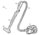
以下、この発明の実施の形態について、図面を参照して説明する。図1は、この発明の実施の形態に従った電気掃除機の外観図である。まず図1を用いて、この発明の実施の形態に係る電気掃除機400の概略構成について説明する。図1で示すように、電気掃除機400は、掃除機本体部410、吸気口部420、接続管430、接続ホース440、操作ハンドル450などを備えている。掃除機本体部410には、図1では示さない電動送風機、サイクロン集塵機および制御装置などが内蔵されている。
Embodiments of the present invention will be described below with reference to the drawings. FIG. 1 is an external view of a vacuum cleaner according to an embodiment of the present invention. First, a schematic configuration of a
電動送風機は、吸気を行なうための送風ファンおよび送風ファンを回転駆動する送風駆動モータを有している。制御装置は、CPU(Central Processing Unit)、RAM(Random Access Memory)、ROM(Read Only Memory)などの制御機器を有しており、電気掃除機400を統括的に制御する。具体的には、制御装置では、CPUがROMに記憶された制御プログラムに従って種々の処理を実行する。
The electric blower has a blower fan for performing intake air and a blower drive motor that rotationally drives the blower fan. The control device includes control devices such as a CPU (Central Processing Unit), a RAM (Random Access Memory), and a ROM (Read Only Memory), and comprehensively controls the
操作ハンドル450には、ユーザが電気掃除機400の稼動の有無や運転モードの選択操作などを行なうための操作スイッチが設けられている。また、その操作スイッチ近傍には、電気掃除機400の現在の状態を表示するLED(Light Emitting Diodes)などの表示部も設けられている。
The
掃除機本体部410は、掃除機本体部410の前端に接続された接続ホース440と、接続ホース440に接続された接続管430とを介して吸気口部420に接続されている。したがって、電気掃除機400では、掃除機本体部410に内蔵された電動送風機が作動することにより、吸気口部420からの吸気が行なわれる。そして、吸気口部420から吸気された空気は、接続管430および接続ホース440を通じてサイクロン集塵装置に流入する。サイクロン集塵装置では、吸い込まれた空気から塵埃が遠心分離される。なお、サイクロン集塵装置で塵埃が分離された後の空気は、掃除機本体部410の後端に設けられた排気口から排出される。
The vacuum cleaner
以下、本発明に係るサイクロン集塵装置の一例であるサイクロン集塵装置について説明する。 Hereinafter, the cyclone dust collector which is an example of the cyclone dust collector which concerns on this invention is demonstrated.
図2は、この発明の実施の形態に従った電気掃除機で用いられるサイクロン集塵装置の底面図である。図3は、図2中のIII−III線に沿ったサイクロン集塵装置の内部構造を説明するための断面図である。図4は、図2中のIV−IV線に沿ったサイクロン集塵装置の内部構造を説明するための断面図である。 FIG. 2 is a bottom view of the cyclone dust collector used in the vacuum cleaner according to the embodiment of the present invention. FIG. 3 is a cross-sectional view for explaining the internal structure of the cyclone dust collector along the line III-III in FIG. FIG. 4 is a cross-sectional view for explaining the internal structure of the cyclone dust collector along the line IV-IV in FIG.
図2から図4で示すように、サイクロン集塵装置300は、筐体10、内周面がほぼ円筒状で、上記筐体10に対して着脱自在の集塵容器11(捕集容器の一例)、内筒12、上部フィルタユニット13、塵埃受部14および除塵駆動機構などを備えて概略構成されている。
As shown in FIG. 2 to FIG. 4, the cyclone
サイクロン集塵装置300では、集塵容器11、内筒12、上部フィルタユニット13および塵埃受部14が、垂直の中心軸Pを中心に同軸上に配置されている。また、サイクロン集塵装置300は、掃除機本体部410に着脱可能に構成されている。
In the cyclone
上記上蓋の一例である筐体10は、内筒フィルタ122を備えた内筒12を備えている。
The
このサイクロン集塵装置300では、ほぼ円筒状の集塵容器11の中心部に設けられた内筒12から集塵容器11の空気を排気することにより、集塵容器11の内周部に設けられた空気流入口111aから吸い込まれた空気を集塵容器11の内周面に沿って旋回させた後、フィルタ手段の一例である上部フィルタユニット13などを経て内筒12を経て排気し、空気に含まれる比較的大きい捕集対象物を集塵容器11の底部で捕集するとともに、比較的小さい捕集対象物を上部フィルタユニット13などにおいて捕集するものである。
In the cyclone
集塵容器11は、吸い込まれた空気から分離された塵埃を収容するための内周面が円筒状で、かつ外形も円筒状の容器である。集塵容器11は、サイクロン集塵装置300の筐体10に着脱可能に構成されている。
The
集塵容器11の底部には、底蓋310が開閉自在に取付けられている。図2では底蓋310が閉じた状態を示している。ユーザは、掃除機本体部410からサイクロン集塵装置300を取り出した後、底蓋310を開くことで集塵容器11内の塵埃を廃棄する。
A
サイクロン集塵装置300の筐体10と集塵容器11との間には、環状のシール部材161が設けられている。このシール部材161により、筐体10および集塵容器11間の空気の漏れが防止できる。
An
また、集塵容器11の底蓋310には、内筒12に設けられた回転軸部123bに嵌合する嵌合部11aが設けられている。嵌合部11aの外周部には、内筒12の回転軸部123bとの隙間を埋めるための環状のシール部材11bが設けられている。このシール部材11bにより、回転軸部123bおよび集塵容器11の間の空気の漏れを防止できる。
In addition, the
さらに、集塵容器11には、接続ホース440が接続される接続部111が設けられている。吸気口部420から接続管430および接続ホース440を通じて吸い込まれた空気は、接続部111から集塵容器11内に流入する。
Furthermore, the
接続部111の集塵容器11への空気流入口111aは、接続ホース440からの空気が集塵容器11内で旋回するように形成されている。具体的には、空気流入口111aは、集塵容器11の接線方向に向くように形成されていることで、空気流入口111aから吸い込まれた空気は集塵容器11の内周に沿って旋回する。したがって、旋回する空気に含まれた塵埃は旋回により遠心力で集塵容器11の内周面に押し付けられ、そのために旋回の速度を失って集塵容器11の底に落下し、旋回空気から分離(遠心分離)される。そして、集塵容器11で遠心分離された塵埃は、集塵容器11の底部に収容される。
The
一方、塵埃が分離された後の空気は、集塵容器11から矢印112aで示す排気経路に沿って掃除機本体部410に設けられた排出口から外部に排気される。ここで、集塵容器11から排気口までの排気経路112上には、内筒12、塵埃受部14および上部フィルタユニット13が順に配置されており、空気流中の比較的細かい塵埃が内筒12および上部フィルタユニット13に設けられたフィルタにより取り除かれる。
On the other hand, the air after the dust is separated is exhausted from the
内筒12は、集塵容器11内に配置された円筒状の部材である。ここで、内筒12は、塵埃受部14によって回転可能に支持されている。具体的に、内筒12は、内筒12の上端に設けられた環状の凹部12aが塵埃受部14の下端に設けられた環状の支持部14cに支持されることにより、塵埃受部14と一体に回転可能な状態で吊り下げられている。なお、内筒12を回転可能に支持する構成は、これに限られるものではない。たとえば内筒12の上下の端部を軸支することが一例として考えられる。
The
内筒12は、傾斜除塵部材134に一体回転可能に連結されている。これにより、内筒12は、傾斜除塵部材134に連動して回転することになる。なお、内筒12および傾斜除塵部材134の連結構造はこれに限られない。たとえば、内筒12および傾斜除塵部材134各々に設けられた嵌合部を嵌合させることにより一体回転可能に連結する構成が考えられる。
The
また、内筒12の上部には、集塵容器11で塵埃が分離された後の空気を、上部フィルタユニット13に向けて排気するための内筒排気口121が形成されている。そして、内筒排気口121には、内筒排気口121全体を覆う内筒状をなす内筒フィルタ122が設けられている。内筒フィルタ122は、内筒排気口121を通過する空気を濾過する。
In addition, an inner
たとえば、内筒フィルタ122は、メッシュ状のエアフィルタなどである。なお、内筒フィルタ122は、内筒排気口121の内側または外側のいずれに設けられていてもよい。また、内筒排気口121および内筒フィルタ122に代えて、内筒12にメッシュ状の孔を形成する構成も考えられる。その場合は、メッシュ状の孔が内筒排気口121および内筒フィルタ122として機能する。
For example, the
図2で示す底面図では、回動機構510と底蓋310とを結ぶ線の両側に第一係合部520および第二係合部530が設けられている。このような配置とすることで、回動機構510、第一係合部520および第二係合部530により確実に底蓋310を集塵容器11に固定することができる。
In the bottom view shown in FIG. 2, a
図5は、ある方向から見たサイクロン集塵装置300の構造を示す斜視図である。図6は、別の方向から見たサイクロン集塵装置300の構造を示す斜視図である。図5および図6を参照して、底蓋310は、回動機構510により集塵容器11に回動可能に取付けられている。底蓋310は開口330を封止しており、開口から塵埃が漏れることを防止している。底蓋310は、回動機構510、第一係合部520および第二係合部530により集塵容器11に保持されている。操作部540を操作することで第一係合部520および第二係合部530の係合が外れて、底蓋310が回動機構510を中心として回動する。これにより開口330が露出して集塵容器11から塵埃を排出することができる。
FIG. 5 is a perspective view showing the structure of the cyclone
図7は、底蓋310が開いた状態を示す斜視図である。図7で示すように、第一係合部520および第二係合部530と底蓋310との係合が解除されると、底蓋310は回動機構510を中心として回動して開口330が露出する。これにより、螺旋状回転圧縮部123によって圧縮された塵埃が開口330から排出される。
FIG. 7 is a perspective view showing a state in which the
図8は、集塵容器11に設けられる操作部540の構成を詳細に説明するための斜視図である。図9は、操作部540が操作されて第一係合部520および第二係合部530による係合が解除された状態を示す斜視図である。図8および図9を参照して、操作部540は、集塵容器11の外周面に沿って延びるアーム部541に接続されている。アーム部541のアーム側先端部542,543は、第一係合部520および第二係合部530に設けられた係合部側先端部521,531と当接しており、当接面がテーパ面とされている。これによりアーム部541が円周方向にスライド移動することにより、係合部側先端部521,531が半径方向に移動する。その結果、第一係合部520および第二係合部530が回動して第一係合部520および第二係合部530と底蓋310との係合が解除される。第一係合部520および第二係合部530はバネ522,532により付勢されている。
FIG. 8 is a perspective view for explaining the configuration of the
図10は、筐体10と、筐体10に取り付けられた螺旋状回転圧縮部123とを拡大して示す斜視図である。図11は、筐体10の内部構成を説明するために示す分解斜視図である。
FIG. 10 is an enlarged perspective view showing the
内筒12の下部には、集塵容器11の塵埃を圧縮するための垂直中心軸周りに回転可能な螺旋状回転圧縮部123が設けられている。螺旋状回転圧縮部の斜視図である図4を参照しつつ螺旋状回転圧縮部123について説明する。
At the lower part of the
図2および図3で示されているように、螺旋状回転圧縮部123には、螺旋状曲面を備えた螺旋部123aと、回転軸部123bと、円盤状遮蔽部材123cとが設けられている。
As shown in FIGS. 2 and 3, the spiral
回転軸部123bは、集塵容器11の底部に設けられた嵌合部11aに嵌合される中空円筒である。前述したように、回転軸部123bおよび嵌合部11aの間にはシール部材11bが介在する。
The
円盤状遮蔽部材123cは、集塵容器11内において、旋回流の遠心分離力により塵埃を分離する上部空間の部分(分離部104)と、塵埃を蓄積する下部空間の部分(集塵部105)との仕切りの役割を果たす。これにより、捕集した塵埃が巻き上がり、内筒フィルタ122を詰まらせることを防ぐ。また円盤状であるため、サイクロン気流中に含まれる塵埃が引っかかることがなく、効率的に塵埃を集塵容器11の底部へ誘導することができる。
The disc-shaped
回転軸部123bには、回転軸部123bを中心にして、集塵部105の底面に向かった螺旋状に延び、その上下面が垂直中心軸Pを中心とする螺旋状曲面を備えた湾曲した板状の螺旋部123a(圧縮部材の一部)が設けられている。螺旋部123aは、後述するように内筒12が回転するときに集塵容器11内に蓄積され、集塵容器11の内周面に接触して回転させることに抵抗がある集塵を、ねじの運び作用によって集塵容器11の底部に向かって移動させる。このとき、圧縮部材の螺旋状曲面が螺旋状曲面をねじと想定したときに圧縮部材の回転によりねじが後退するように形成されることにより、この螺旋状曲面で塵を圧縮することができる。
The
このとき、螺旋部123aの螺旋状曲面は旋回気流と同様の傾斜方向をもって形成されることが好ましい。このような螺旋部123aを旋回と反対方向に回転させることで集塵容器11内の塵埃は、集塵容器11内面との摩擦によって、集塵容器11底部へ移動することになる。
At this time, the spiral curved surface of the
但し、螺旋部123aの螺旋状曲面を、集塵容器11の内周面に沿って旋回する気流の傾きとは反対方向に傾斜させることも可能である。このとき、螺旋部123aの回転方向は旋回気流の旋回方向と同一方向、すなわち螺旋部123aをねじと想定したとき、螺旋部123aの回転によりねじが後退する方向となる。
However, it is also possible to incline the spiral curved surface of the
さらに、内筒12が回転するとき、集塵容器11の底部まで移動した塵埃に対して螺旋部123aは集塵容器11の底部との摩擦によって上記底面との間で塵埃を回転により回転軸中心から外側に向かって押出し圧縮することになる。このような構成とすれば、塵埃が回転によって固く圧縮されるので、集塵容器11の塵埃の蓄積可能量を増加させることができる。したがって、集塵容器11の小型化を実現することも可能である。また固く圧縮された塵埃は、容易に解けないので、取出し時にも空気中に散乱する問題がなく、そのままの形で塵として廃棄することができる。
Further, when the
また、上記のように螺旋状回転圧縮部123が螺旋状回転圧縮部が回転することによって螺旋部123aにより圧縮された塵埃の一部は、長い髪の毛などを含んでいるので螺旋部123aに絡みつく。そのため、上記のように底蓋310を開放して、集塵容器11の底部に形成した開口330から塵埃を放出しようとしても簡単には外部に放出されない。また、塵埃を勢いよく放出すると塵埃に含まれる細かいちりなどが空気中に散乱し、部屋を汚すことになる。そのため、何らかの方法で、簡単な操作で塵埃をゆっくり外部に放出する機構が必要である。そのために設けられた塵埃を簡単な操作でゆっくり外部に放出するための機構について以下に説明する。
In addition, as described above, a part of the dust compressed by the
上部フィルタユニット13を内部に備えた筐体10の上面には取っ手314が設けられている。取っ手314は外部から操作可能な操作部材の一例である。
A
取っ手314は、筐体10とは独立して垂直軸芯の周りに回転自在である。取っ手314の内部には、傾斜面を構成する上側取っ手内蔵ギヤ316が一体に内蔵されており、上側取っ手内蔵ギヤ316と同じく斜面を構成する下側取っ手内蔵ギヤ318が噛合っている。上側取っ手内蔵ギヤ316が回転すると下側取っ手内蔵ギヤ318が上記傾斜に押されて下方向に移動する。したがって、取っ手314を回転させることで上側取っ手内蔵ギヤ316が下側取っ手内蔵ギヤ318と噛合って取っ手314の回転が下側取っ手内蔵ギヤ318に伝えられる。
The
下側取っ手内蔵ギヤ318は、中間体320の上面に形成されており、中間体320の下面にはクラッチギヤが形成されているので、下側取っ手内蔵ギヤ318の下方への移動により中間体320とともにクラッチギヤも下方向に移動することになる。
The lower handle built-in
中間体320の下方には、隙間を介してフィルタ除塵部材132に一体的に固定されたクラッチ受部が設けられており、上記中間体320の下方への移動に伴ってクラッチギヤとクラッチ受部とが噛合い、取っ手314の回転がクラッチギヤとクラッチ受部から構成されるクラッチ機構を介して、フィルタ除塵部材132に伝達され、フィルタ除塵部材132に連結された内筒12およびこれと一体に連結された螺旋状回転圧縮部123が回転し、螺旋部132aが回転する。これによって、螺旋部123aのねじの運び作用により螺旋部123aに絡まった塵埃がゆっくりと螺旋部123aの先端方向に運ばれ、底蓋310が開くことによって開放された集塵容器11の底部開口から外部に放出される。
A clutch receiving portion that is integrally fixed to the filter
このように操作者によって取っ手314が回転されることで塵埃がゆっくりと外部に放出されるので、塵埃に含まれる細かい塵などが舞い上ることを防止し、また、塵が飛散することなく室内がちりによって汚染されることがない。
As the
なお、取っ手314から手を離すとばね収容部に内蔵されたばねによって中間体320が押し上げられ、クラッチギヤとクラッチ受部から構成されるクラッチ機構が開放される。これによって、取っ手314を操作しない限りクラッチ機構が開放状態にあるので、除塵駆動モータ151によってフィルタ除塵部材132が回転しても取っ手314が回転しないので安全である。
When the hand is released from the
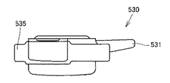
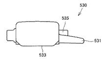
図12は、この発明の実施の形態に従った第二係合部530の正面図である。図13は、図12中の矢印XIIIで示す方向から見た平面図である。図14は、図12中の矢印XIVで示す方向から見た底面図である。図15は、図12中の矢印XVで示す方向から見た左側面図である。図16は、図12中の矢印XVIで示す方向から見た右側面図である。図17は、図16中の矢印XVIIで示す方向から見た背面図である。図18は、図12中の矢印XVIIIで示す方向から見た平面図である。図19は、図12中のXIX−XIX線に沿った断面図である。図20は、図12中のXX−XX線に沿った断面図である。図21は、図12中のXXI−XXI線に沿った断面図である。
FIG. 12 is a front view of
これらの図を参照して、第二係合部530は回動軸となるシャフト部535を有する。シャフト部535は円柱状であり、集塵容器11の円周方向に沿って延びるように形成されている。シャフト部535が集塵容器11に回動可能に保持されている。
With reference to these drawings, the
係合部側端部531はシャフト部535の延びる方向に向かって突出しており、アーム部から力が加えられる。この実施の形態では1つの操作部540を操作することで第一係合部520および第二係合部530の係合を解除するためにアーム部541を設けているが、第一操作部が第一係合部520の係合を解除し、第二操作部が第二係合部530の係合を解除する構成を採用するのであれば、アーム部541を設ける必要はない。
The engaging portion
第二係合部530の下端には、係合端部533が設けられている。係合端部533は底蓋310の外周部を受け入れる形状をしており、第二係合部530がシャフト部535を中心に回動することで係合端部533と底蓋310との係合が解除される。
An
この発明に従った電気掃除機は、塵埃を含む旋回気流を導入する導入口および空気の出口となる開口を有し、旋回気流により塵埃を集塵する集塵容器を有し、集塵容器には塵埃を排出するための開口が設けられているサイクロン集塵装置と集塵室内にて塵埃を圧縮する螺旋状回転圧縮部123と,開口330に嵌め合わせられる底蓋310と、底蓋310を集塵容器11に回動可能に取付ける回動機構510と、底蓋310を集塵容器11に係合させることが可能な第一および第二係合部520,530とを備え、回動機構510と底蓋310の中心とを結ぶ線500aの両側に第一および第二係合部520,530がそれぞれ設けられ、螺旋状回転圧縮部123で圧縮された塵埃は第一および第二係合部520,530による係合が解除されて底蓋310が開かれることで開口330から集塵容器11外へ排出される。
The vacuum cleaner according to the present invention has an inlet that introduces a swirling airflow containing dust and an opening that serves as an air outlet, and has a dust collecting container that collects dust by the swirling airflow. Includes a cyclone dust collecting device provided with an opening for discharging dust, a spiral
電気掃除機は、第一および第二係合部520,530に接続された操作部540をさらに備え、操作部540が操作させることで第一および第二係合部520,530における底蓋310と集塵容器11との係合が解除される。
The vacuum cleaner further includes an
図22は、別の局面に従った電気掃除機における第一および第二係合部520,530の構成を説明するために示す底面図である。図22を参照して、第一係合部520および第二係合部530が連結されており、1つの部材で構成されていてもよい。操作部540に円弧形状のアーム部560が接続され、その先端部が第一係合部520および第二係合部530となっている。しかし、この場合であっても第一係合部520および第二係合部530は、回動機構510と底蓋310の中心とを通る直線の両側に設けられている。
FIG. 22 is a bottom view for explaining the configuration of first and second engaging
今回開示された実施の形態はすべての点で例示であって制限的なものではないと考えられるべきである。本発明の範囲は上記した説明ではなくて特許請求の範囲によって示され、特許請求の範囲と均等の意味および範囲内でのすべての変更が含まれることが意図される。 The embodiment disclosed this time should be considered as illustrative in all points and not restrictive. The scope of the present invention is defined by the terms of the claims, rather than the description above, and is intended to include any modifications within the scope and meaning equivalent to the terms of the claims.
10 筐体、11b シール部材、11a 嵌合部、11 集塵容器、12 内筒、12a 凹部、13 上部フィルタユニット、14 塵埃受部、14c 支持部、41,42 凸部、104 分離部、105 集塵部、111 接続部、111a 空気流入口、112 排気経路、112a 矢印、121 内筒排気口、122 内筒フィルタ、123c 円盤状遮蔽部材、123b 回転軸部、123 螺旋状回転圧縮部、123a 螺旋部、132 フィルタ除塵部材、132a 螺旋部、134 傾斜除塵部材、161 シール部材、300 サイクロン集塵装置、310 底蓋、320 中間体、330 開口、400 電気掃除機、410 掃除機本体部、420 吸気口部、430 接続管、440 接続ホース、450 操作ハンドル、510 回動機構、520 第一係合部、530 第二係合部、540 操作部。
DESCRIPTION OF
Claims (2)
前記集塵室内にて塵埃を圧縮する圧縮部と,
前記開口に嵌め合わせられる蓋部と、
前記蓋部を前記集塵容器に回動可能に取付ける回動機構と、
前記蓋部を前記容器に係合させることが可能な第一および第二係合部とを備え、
前記回動機構と前記蓋部の中心とを結ぶ線の両側に前記第一および第二係合部がそれぞれ設けられ、
前記圧縮部で圧縮された塵埃は前記第一および第二係合部による係合が解除されて前記蓋部が開かれることで開口から集塵容器外へ排出される、電気掃除機。 An opening for introducing a swirling airflow containing dust and an opening serving as an air outlet; a dust collecting container for collecting dust by the swirling airflow; and an opening for discharging dust in the dust collecting container. A cyclone dust collector provided, a compression unit for compressing dust in the dust collection chamber,
A lid portion fitted into the opening;
A rotation mechanism for rotatably attaching the lid to the dust collecting container;
A first and a second engagement portion capable of engaging the lid portion with the container;
The first and second engaging portions are respectively provided on both sides of a line connecting the turning mechanism and the center of the lid portion,
The vacuum cleaner, wherein the dust compressed by the compression unit is discharged from the opening to the outside of the dust collecting container by releasing the engagement by the first and second engagement units and opening the lid.
Priority Applications (2)
| Application Number | Priority Date | Filing Date | Title |
|---|---|---|---|
| JP2008278305A JP2010104502A (en) | 2008-10-29 | 2008-10-29 | Vacuum cleaner |
| CN2009102058896A CN101721167B (en) | 2008-10-29 | 2009-10-21 | Electric dust collector |
Applications Claiming Priority (1)
| Application Number | Priority Date | Filing Date | Title |
|---|---|---|---|
| JP2008278305A JP2010104502A (en) | 2008-10-29 | 2008-10-29 | Vacuum cleaner |
Publications (1)
| Publication Number | Publication Date |
|---|---|
| JP2010104502A true JP2010104502A (en) | 2010-05-13 |
Family
ID=42294556
Family Applications (1)
| Application Number | Title | Priority Date | Filing Date |
|---|---|---|---|
| JP2008278305A Pending JP2010104502A (en) | 2008-10-29 | 2008-10-29 | Vacuum cleaner |
Country Status (2)
| Country | Link |
|---|---|
| JP (1) | JP2010104502A (en) |
| CN (1) | CN101721167B (en) |
Cited By (4)
| Publication number | Priority date | Publication date | Assignee | Title |
|---|---|---|---|---|
| JP2012024112A (en) * | 2010-06-25 | 2012-02-09 | Hitachi Appliances Inc | Vacuum cleaner |
| CN104107007A (en) * | 2013-04-18 | 2014-10-22 | Lg电子株式会社 | Vacuum cleaner |
| KR101452673B1 (en) | 2012-05-11 | 2014-10-22 | 가부시끼가이샤 도시바 | Electrical cleaner |
| JP2017060848A (en) * | 2016-12-01 | 2017-03-30 | 日立アプライアンス株式会社 | Vacuum cleaner |
Families Citing this family (4)
| Publication number | Priority date | Publication date | Assignee | Title |
|---|---|---|---|---|
| GB2487599B (en) * | 2011-01-31 | 2015-04-08 | Hoover Ltd | Cyclonic separator |
| GB2598506B (en) * | 2017-06-19 | 2022-06-08 | Techtronic Floor Care Tech Ltd | A dirt separation device |
| JP7244370B2 (en) * | 2019-06-26 | 2023-03-22 | 日立グローバルライフソリューションズ株式会社 | vacuum cleaner |
| CN113273925B (en) * | 2020-02-03 | 2023-12-29 | 朱圣铉 | Dust collecting device of vacuum cleaner |
Citations (5)
| Publication number | Priority date | Publication date | Assignee | Title |
|---|---|---|---|---|
| JPH10203547A (en) * | 1997-01-17 | 1998-08-04 | Shiseido Co Ltd | Lid engagement structure |
| JP2000335608A (en) * | 1999-05-25 | 2000-12-05 | Marugo Kogyo Kk | Lid structure, garbage disposer equipped with this, and electromagnetic wave heating device |
| JP2000342492A (en) * | 1999-01-29 | 2000-12-12 | Sanyo Electric Co Ltd | Dust collector for cleaner and upright cleaner |
| JP2003070698A (en) * | 2001-09-07 | 2003-03-11 | Toshiba Tec Corp | Electric vacuum cleaner |
| JP2004318979A (en) * | 2003-04-15 | 2004-11-11 | Matsushita Electric Ind Co Ltd | Lid opening and closing device |
Family Cites Families (1)
| Publication number | Priority date | Publication date | Assignee | Title |
|---|---|---|---|---|
| JP4682693B2 (en) * | 2005-05-18 | 2011-05-11 | パナソニック株式会社 | Dust collection container and electric vacuum cleaner provided with the same |
-
2008
- 2008-10-29 JP JP2008278305A patent/JP2010104502A/en active Pending
-
2009
- 2009-10-21 CN CN2009102058896A patent/CN101721167B/en not_active Expired - Fee Related
Patent Citations (5)
| Publication number | Priority date | Publication date | Assignee | Title |
|---|---|---|---|---|
| JPH10203547A (en) * | 1997-01-17 | 1998-08-04 | Shiseido Co Ltd | Lid engagement structure |
| JP2000342492A (en) * | 1999-01-29 | 2000-12-12 | Sanyo Electric Co Ltd | Dust collector for cleaner and upright cleaner |
| JP2000335608A (en) * | 1999-05-25 | 2000-12-05 | Marugo Kogyo Kk | Lid structure, garbage disposer equipped with this, and electromagnetic wave heating device |
| JP2003070698A (en) * | 2001-09-07 | 2003-03-11 | Toshiba Tec Corp | Electric vacuum cleaner |
| JP2004318979A (en) * | 2003-04-15 | 2004-11-11 | Matsushita Electric Ind Co Ltd | Lid opening and closing device |
Cited By (4)
| Publication number | Priority date | Publication date | Assignee | Title |
|---|---|---|---|---|
| JP2012024112A (en) * | 2010-06-25 | 2012-02-09 | Hitachi Appliances Inc | Vacuum cleaner |
| KR101452673B1 (en) | 2012-05-11 | 2014-10-22 | 가부시끼가이샤 도시바 | Electrical cleaner |
| CN104107007A (en) * | 2013-04-18 | 2014-10-22 | Lg电子株式会社 | Vacuum cleaner |
| JP2017060848A (en) * | 2016-12-01 | 2017-03-30 | 日立アプライアンス株式会社 | Vacuum cleaner |
Also Published As
| Publication number | Publication date |
|---|---|
| CN101721167A (en) | 2010-06-09 |
| CN101721167B (en) | 2012-10-03 |
Similar Documents
| Publication | Publication Date | Title |
|---|---|---|
| JP2010104502A (en) | Vacuum cleaner | |
| JP4750164B2 (en) | Cyclone separator | |
| JP4657340B2 (en) | Electric vacuum cleaner | |
| JP6867991B2 (en) | Vacuum cleaner | |
| JP5212876B2 (en) | Electric vacuum cleaner | |
| JP5841563B2 (en) | Electric vacuum cleaner | |
| JP4932025B2 (en) | Vacuum cleaner | |
| JP5212874B2 (en) | Electric vacuum cleaner | |
| JP5212875B2 (en) | Electric vacuum cleaner | |
| JP5000011B2 (en) | Electric vacuum cleaner | |
| JP5155481B2 (en) | Electric vacuum cleaner | |
| JP5155480B2 (en) | Electric vacuum cleaner | |
| JP4871416B2 (en) | Cyclone separator | |
| JP4856271B2 (en) | Cyclone separator | |
| JP5291826B2 (en) | Electric vacuum cleaner | |
| JP5154702B2 (en) | Electric vacuum cleaner | |
| JP5155479B2 (en) | Electric vacuum cleaner | |
| JP5291827B2 (en) | Electric vacuum cleaner | |
| JP5155478B2 (en) | Electric vacuum cleaner | |
| JP5155482B2 (en) | Electric vacuum cleaner | |
| JP2016034575A (en) | Vacuum cleaner | |
| JP2018008154A (en) | Vacuum cleaner | |
| WO2015033593A1 (en) | Cyclone dust collector and electric vacuum cleaner with same | |
| JP2015006623A (en) | Cyclone separator, vacuum cleaner | |
| JP2012176319A (en) | Cyclone separator and vacuum cleaner |
Legal Events
| Date | Code | Title | Description |
|---|---|---|---|
| A977 | Report on retrieval |
Effective date: 20100812 Free format text: JAPANESE INTERMEDIATE CODE: A971007 |
|
| A131 | Notification of reasons for refusal |
Effective date: 20100817 Free format text: JAPANESE INTERMEDIATE CODE: A131 |
|
| A521 | Written amendment |
Free format text: JAPANESE INTERMEDIATE CODE: A523 Effective date: 20101015 |
|
| A02 | Decision of refusal |
Free format text: JAPANESE INTERMEDIATE CODE: A02 Effective date: 20101124 |