JP2007287385A - Lighting device, liquid crystal device, and electronic device - Google Patents
Lighting device, liquid crystal device, and electronic device Download PDFInfo
- Publication number
- JP2007287385A JP2007287385A JP2006110915A JP2006110915A JP2007287385A JP 2007287385 A JP2007287385 A JP 2007287385A JP 2006110915 A JP2006110915 A JP 2006110915A JP 2006110915 A JP2006110915 A JP 2006110915A JP 2007287385 A JP2007287385 A JP 2007287385A
- Authority
- JP
- Japan
- Prior art keywords
- light
- light source
- liquid crystal
- blue
- cyan
- Prior art date
- Legal status (The legal status is an assumption and is not a legal conclusion. Google has not performed a legal analysis and makes no representation as to the accuracy of the status listed.)
- Withdrawn
Links
Images


Classifications
-
- G—PHYSICS
- G02—OPTICS
- G02F—OPTICAL DEVICES OR ARRANGEMENTS FOR THE CONTROL OF LIGHT BY MODIFICATION OF THE OPTICAL PROPERTIES OF THE MEDIA OF THE ELEMENTS INVOLVED THEREIN; NON-LINEAR OPTICS; FREQUENCY-CHANGING OF LIGHT; OPTICAL LOGIC ELEMENTS; OPTICAL ANALOGUE/DIGITAL CONVERTERS
- G02F1/00—Devices or arrangements for the control of the intensity, colour, phase, polarisation or direction of light arriving from an independent light source, e.g. switching, gating or modulating; Non-linear optics
- G02F1/01—Devices or arrangements for the control of the intensity, colour, phase, polarisation or direction of light arriving from an independent light source, e.g. switching, gating or modulating; Non-linear optics for the control of the intensity, phase, polarisation or colour
- G02F1/13—Devices or arrangements for the control of the intensity, colour, phase, polarisation or direction of light arriving from an independent light source, e.g. switching, gating or modulating; Non-linear optics for the control of the intensity, phase, polarisation or colour based on liquid crystals, e.g. single liquid crystal display cells
- G02F1/133—Constructional arrangements; Operation of liquid crystal cells; Circuit arrangements
- G02F1/1333—Constructional arrangements; Manufacturing methods
- G02F1/1335—Structural association of cells with optical devices, e.g. polarisers or reflectors
- G02F1/1336—Illuminating devices
- G02F1/133602—Direct backlight
- G02F1/133603—Direct backlight with LEDs
Landscapes
- Liquid Crystal (AREA)
- Led Device Packages (AREA)
- Planar Illumination Modules (AREA)
Abstract
【課題】スペクトル上で2つのピークを持つ光源を用いた照明装置によって被照明体を照
明したときに、その被照明体において高い輝度及び広い色度域を得る。
【解決手段】出射光がスペクトル上で2つのピークWb,Wyを持つ光源ユニットと、2
つのピークWb,Wyの少なくとも一方の谷に相当する波長部分Wcにピークを持つ単色
光源とを有する照明装置である。B(青),G(緑),R(赤),C(シアン)の4色の
着色膜を有するカラーフィルタに照明装置によって光を供給するとき、シアンの透過光の
輝度を向上し、色の再現性を向上する。
【選択図】図7
When an object to be illuminated is illuminated by an illumination device using a light source having two peaks in the spectrum, high luminance and a wide chromaticity range are obtained in the object to be illuminated.
A light source unit in which emitted light has two peaks Wb and Wy on a spectrum, and 2
And a monochromatic light source having a peak in a wavelength portion Wc corresponding to at least one valley of the two peaks Wb and Wy. When light is supplied by a lighting device to a color filter having four colored films of B (blue), G (green), R (red), and C (cyan), the luminance of the cyan transmitted light is improved, Improve reproducibility.
[Selection] Figure 7
Description
本発明は、光を出射する照明装置、その照明装置を用いた液晶装置、及びその液晶装置
を用いた電子機器に関する。
The present invention relates to an illumination device that emits light, a liquid crystal device using the illumination device, and an electronic apparatus using the liquid crystal device.
現在、携帯電話機、携帯情報端末機、液晶テレビ等といった電子機器に液晶装置が広く
用いられている。例えば、各種の情報を画像として表示するために液晶装置が用いられて
いる。液晶装置は、液晶層を通過する光を変調することにより画像を表示する電気光学装
置である。液晶層に光を供給するために、液晶装置に照明装置が付設されることがある。
Currently, liquid crystal devices are widely used in electronic devices such as mobile phones, portable information terminals, and liquid crystal televisions. For example, a liquid crystal device is used to display various types of information as images. A liquid crystal device is an electro-optical device that displays an image by modulating light passing through a liquid crystal layer. In order to supply light to the liquid crystal layer, an illumination device may be attached to the liquid crystal device.
照明装置として、従来、発光ダイオードの光出射範囲を重ねることにより2種類の発光
を合成して白色光に調光する照明装置が知られている(例えば、特許文献1参照)。また
、導光板に蛍光体を塗布することにより出射光の強度ムラを低減した照明装置が知られて
いる(例えば、特許文献2参照)。
2. Description of the Related Art Conventionally, as a lighting device, there is known a lighting device that adjusts white light by combining two types of light emission by overlapping light emitting ranges of light emitting diodes (see, for example, Patent Document 1). There is also known an illumination device that reduces intensity unevenness of emitted light by applying a phosphor to a light guide plate (see, for example, Patent Document 2).
特許文献1及び特許文献2に開示された照明装置では、光源として白色光源が用いられ
ている。この白色光源は、青色発光ダイオードとYAG蛍光体との組合せによって白色光
を得るものである。この白色光源は、スペクトル上で青色とYAG蛍光色との2つの波長
部分にピークを有する光分布特性を有している。この光分布特性が被照明体、例えばカラ
ーフィルタの分光分布特性に一致していれば、被照明体を透過した後の光に関して、高い
輝度及び広い色度域を得ることができる。しかしながら、白色光源の光分布特性と被照明
体の分光分布特性が一致していないと、高い輝度及び広い色度域を得ることができないと
いう問題がある。
In the illumination devices disclosed in
本発明は、上記の問題点に鑑みて成されたものであって、スペクトル上で2つの波長部
分にピークがある光分布特性を有する光源を用いた照明装置によって被照明体を照明した
ときに、その被照明体において高い輝度及び広い色度域を得ることができるようにするこ
とを目的とする。
The present invention has been made in view of the above problems, and when an object to be illuminated is illuminated by an illumination device using a light source having a light distribution characteristic having peaks at two wavelength portions on the spectrum. An object of the present invention is to obtain a high luminance and a wide chromaticity range in the object to be illuminated.
本発明に係る照明装置は、出射光がスペクトル上で少なくとも2つのピークを持つ光源
ユニットと、前記2つのピークの少なくとも一方の谷に相当する波長部分にピークを持つ
単色光源とを有することを特徴とする。光源ユニットとは、1つのまとまった光源という
ことであり、その中に1つ又は複数の発光素子が含まれるユニットのことである。この光
源ユニットとしては、1つの発光素子の光出射領域内に蛍光体を設けた構成から成る光源
ユニットや、複数の発光素子を一体に有する光源ユニット等が考えられる。発光素子は任
意の構成の発光素子を適用でき、例えば、発光ダイオード、冷陰極管、有機EL(Electr
o-luminescence)等を用いることができる。上記の単色光源も、任意の構成の発光素子に
よって構成でき、例えば、発光ダイオード、冷陰極管、有機EL(Electro-luminescence
)を用い構成できる。
The illuminating device according to the present invention includes a light source unit in which emitted light has at least two peaks on a spectrum, and a monochromatic light source having a peak in a wavelength portion corresponding to at least one valley of the two peaks. And The light source unit is a single light source, and is a unit including one or a plurality of light emitting elements. As the light source unit, a light source unit having a configuration in which a phosphor is provided in a light emitting region of one light emitting element, a light source unit integrally including a plurality of light emitting elements, and the like are conceivable. A light emitting element having any configuration can be applied. For example, a light emitting diode, a cold cathode tube, an organic EL (Electr
o-luminescence) and the like can be used. The above monochromatic light source can also be configured by a light emitting element having an arbitrary configuration, such as a light emitting diode, a cold cathode tube, an organic EL (Electro-luminescence).
).
上記構成の本発明に係る照明装置によれば、2つのピークを持つ光源ユニットに加えて
、当該2つのピークの少なくとも一方の谷に相当する波長部分にピークを持つ単色光源を
有するので、光源ユニットの出射光のスペクトルにおいて欠けている波長部分を単色光源
の出射光によって補償できる。この結果、照明装置として広い色度域を得ることができる
。さらに、被照明体として複数の着色領域を有するカラーフィルタを考えたとき、より高
い輝度(すなわち、より高い透過率)を得ることができ、さらに、カラーフィルタの出射
光として広い色度域を得ることができる。
According to the illuminating device of the present invention having the above configuration, in addition to the light source unit having two peaks, the light source unit has a monochromatic light source having a peak in a wavelength portion corresponding to at least one valley of the two peaks. The wavelength portion lacking in the spectrum of the emitted light can be compensated by the emitted light of the monochromatic light source. As a result, a wide chromaticity range can be obtained as the lighting device. Furthermore, when a color filter having a plurality of colored regions is considered as an object to be illuminated, higher luminance (that is, higher transmittance) can be obtained, and further, a wide chromaticity region can be obtained as emitted light from the color filter. be able to.
次に、本発明に係る照明装置において、前記単色光源は、前記光源ユニットの中に含ま
れるものであっても良いし、あるいは、前記光源ユニットと別体であっても良い。単色光
源を光源ユニットの中に含めることにすれば、すなわち、光源ユニット内の発光素子と単
色光源とを一体に形成すれば、発光素子の出射光と単色光源の出射光との混光を促進でき
る。
Next, in the illumination device according to the present invention, the monochromatic light source may be included in the light source unit, or may be separate from the light source unit. If a monochromatic light source is included in the light source unit, that is, if the light emitting element in the light source unit and the monochromatic light source are integrally formed, the light mixture of the light emitted from the light emitting element and the light emitted from the monochromatic light source is promoted. it can.
次に、本発明に係る照明装置において、光源ユニットは、例えば、第1の発光ダイオー
ドと、該第1の発光ダイオードの出射光を吸収して当該出射光の補色となる出射光を発光
する蛍光体とを有する構成とすることができる。この光源ユニットによれば、光源ユニッ
トから白色光を出射できる。第1の発光ダイオードは、例えば青色光を出射する発光ダイ
オードとすることができる。蛍光体としては、例えば、YAG蛍光体を適用できる。
Next, in the illumination device according to the present invention, the light source unit includes, for example, a first light emitting diode and a fluorescent light that absorbs the emitted light of the first light emitting diode and emits the emitted light that is a complementary color of the emitted light. It can be set as the structure which has a body. According to this light source unit, white light can be emitted from the light source unit. The first light emitting diode can be, for example, a light emitting diode that emits blue light. For example, a YAG phosphor can be applied as the phosphor.
次に、本発明に係る照明装置において、上記光源ユニット内の発光素子及び上記単色光
源は、いずれも、発光ダイオードによって構成されることが望ましい。発光ダイオードは
、それへの通電を制御することによって容易に輝度を制御できる。従って、光源ユニット
内の発光素子及び単色光源の両方を発光ダイオードによって構成すれば、照明装置から出
る光の色度及び輝度を容易に所望の状態に設定できる。
Next, in the illuminating device according to the present invention, it is desirable that both the light emitting element in the light source unit and the monochromatic light source are constituted by light emitting diodes. The brightness of the light emitting diode can be easily controlled by controlling the energization thereto. Therefore, if both the light emitting element and the monochromatic light source in the light source unit are configured by light emitting diodes, the chromaticity and luminance of light emitted from the lighting device can be easily set to a desired state.
次に、本発明に係る照明装置において、前記第1の発光ダイオードは青色光を出射する
発光ダイオードであり、前記蛍光体はYAG(イットリウム・アルミニウム・ガーネット
)系の蛍光体であり、前記単色光源はシアン色光を出射する光源であることが望ましい。
Next, in the illumination device according to the present invention, the first light emitting diode is a light emitting diode that emits blue light, the phosphor is a YAG (yttrium, aluminum, garnet) phosphor, and the monochromatic light source. Is preferably a light source that emits cyan light.
この構成によれば、第1の発光ダイオードとYAG蛍光体とによって白色光(特に、青
の波長部分及びYAG蛍光の波長部分にピークを有する白色光)を得ることができ、さら
に、単色光源によってシアンの波長部分にピークを付与できる。この構成によれば、照明
装置におけるシアン色の輝度が上がるため、被照明体として、B(青)、G(緑)、R(
赤)、C(シアン)の4色の着色領域を有するカラーフィルタを用いる場合に、カラーフ
ィルタの全体としての光透過率を上げることができる。また、カラーフィルタを透過した
光の色の色純度が上がり、その結果、カラーフィルタの透過光の色度域を上げることがで
きる。
According to this configuration, white light (particularly, white light having a peak in the blue wavelength portion and the YAG fluorescence wavelength portion) can be obtained by the first light emitting diode and the YAG phosphor, and further, by the monochromatic light source. A peak can be imparted to the cyan wavelength portion. According to this configuration, since the luminance of cyan in the lighting device is increased, B (blue), G (green), R (
When a color filter having four colored regions of red and C (cyan) is used, the light transmittance of the color filter as a whole can be increased. Further, the color purity of the color of light transmitted through the color filter is increased, and as a result, the chromaticity range of the transmitted light of the color filter can be increased.
次に、本発明に係る照明装置において、前記第1の発光ダイオードは青色光を出射する
発光ダイオードであり、前記蛍光体はYAG系の蛍光体であり、前記単色光源は緑色光を
出射する光源であることが望ましい。
Next, in the illumination device according to the present invention, the first light emitting diode is a light emitting diode that emits blue light, the phosphor is a YAG-based phosphor, and the monochromatic light source is a light source that emits green light. It is desirable that
この構成によれば、第1の発光ダイオードとYAG蛍光体とによって白色光(特に、青
の波長部分及びYAG蛍光の波長部分にピークを有する白色光)を得ることができ、さら
に、単色光源によって緑の波長部分のピークを高めることができる。青色発光ダイオード
とYAG蛍光体を用いた白色光源では、緑の波長部分の光強度が比較的低い傾向にある。
従って、単色光源によって緑色光を付加することにした本発明態様によれば、照明光及び
B、G、Rのカラーフィルタを透過した透過光において緑の波長部分を補償できる。
According to this configuration, white light (particularly, white light having a peak in the blue wavelength portion and the YAG fluorescence wavelength portion) can be obtained by the first light emitting diode and the YAG phosphor, and further, by the monochromatic light source. The peak of the green wavelength portion can be increased. In a white light source using a blue light emitting diode and a YAG phosphor, the light intensity in the green wavelength portion tends to be relatively low.
Therefore, according to the aspect of the present invention in which the green light is added by the monochromatic light source, the green wavelength portion can be compensated for in the illumination light and the transmitted light transmitted through the B, G, and R color filters.
次に、本発明に係る照明装置において、前記第1の発光ダイオードは青色光を出射する
発光ダイオードであり、前記蛍光体はYAG系の蛍光体であり、前記単色光源は赤色光を
出射する光源であることが望ましい。
Next, in the illumination device according to the present invention, the first light emitting diode is a light emitting diode that emits blue light, the phosphor is a YAG-based phosphor, and the monochromatic light source emits red light. It is desirable that
この構成によれば、第1の発光ダイオードとYAG蛍光体とによって白色光(特に、青
の波長部分及びYAG蛍光の波長部分にピークを有する白色光)を得ることができ、さら
に、単色光源によって赤の波長部分にピークを付与できる。一般に、青色発光ダイオード
とYAG蛍光体を用いた白色光源では、赤の波長部分にピークが無いため、被照明体とし
てB,G,Rのカラーフィルタを用いた場合、カラーフィルタを透過した透過光において
赤が不鮮明になるおそれがある。これに対し、照明装置において赤の波長部分を補償した
本発明態様によれば、カラーフィルタの全体としての光透過率を上げることができる。ま
た、カラーフィルタを透過した光の色の色純度が上がり、その結果、カラーフィルタの透
過光の色度域を上げることができる。
According to this configuration, white light (particularly, white light having a peak in the blue wavelength portion and the YAG fluorescence wavelength portion) can be obtained by the first light emitting diode and the YAG phosphor, and further, by the monochromatic light source. A peak can be given to the red wavelength portion. In general, in a white light source using a blue light emitting diode and a YAG phosphor, there is no peak in the red wavelength portion. Therefore, when a B, G, R color filter is used as an illumination object, transmitted light that has passed through the color filter is transmitted. There is a risk that the red color will be blurred. On the other hand, according to the aspect of the present invention in which the red wavelength portion is compensated for in the illumination device, the light transmittance of the entire color filter can be increased. Further, the color purity of the color of light transmitted through the color filter is increased, and as a result, the chromaticity range of the transmitted light of the color filter can be increased.
次に、本発明に係る照明装置はサイドライト方式であっても良いし、平面ライト方式で
あっても良い。サイドライト方式というのは、前記光源ユニット及び前記単色光源のそれ
ぞれの複数個を、導光体の側面である光入射面に対向して直線的に配列させる方式である
。一方、平面ライト方式というのは、直下型方式とも呼ばれることがある方式であって、
液晶パネル等といった平面的な被照明体に対向して前記光源ユニット及び前記単色光源の
それぞれの複数個を平面的に配列させる方式である。本発明に係る照明装置を平面ライト
方式として用いる場合には、前記複数の単色光源は隣り同士には並ばないように配列する
ことが望ましい。この構成によれば、複数の単色光源が互いに隣り同士に並ぶ場合に比べ
て、光源ユニットから出射される光(例えば、白色光)と単色光源から出射される光(例
えば、シアン、緑、赤等といった単色光)との混光をより一層促進できる。
Next, the lighting device according to the present invention may be a side light method or a flat light method. The side light system is a system in which a plurality of each of the light source unit and the monochromatic light source is linearly arranged facing the light incident surface which is the side surface of the light guide. On the other hand, the flat light method is sometimes called a direct type method,
In this method, a plurality of light source units and monochromatic light sources are arranged in a plane so as to face a planar object to be illuminated such as a liquid crystal panel. When the illumination device according to the present invention is used as a flat light system, it is desirable that the plurality of monochromatic light sources be arranged so as not to be arranged next to each other. According to this configuration, light emitted from the light source unit (for example, white light) and light emitted from the single color light source (for example, cyan, green, red) are compared to a case where a plurality of single-color light sources are arranged next to each other. And so on) can be further promoted.
次に、本発明に係る照明装置に関しては、カラーフィルタを被照明体とすることができ
る。カラーフィルタは、透過し得る光の波長領域が異なる複数の着色領域を有する光学要
素である。カラーフィルタを被照明体とする場合には、前記単色光源の出射光の波長は前
記カラーフィルタのスペクトルのいずれかのピークの波長とほぼ一致することが望ましい
。この構成によれば、カラーフィルタを透過した透過光の色純度を上げることができ、色
度域を広げることができ、透過率を向上できる。
Next, with respect to the illumination device according to the present invention, the color filter can be an object to be illuminated. The color filter is an optical element having a plurality of colored regions having different wavelength regions of light that can be transmitted. When the color filter is an object to be illuminated, it is desirable that the wavelength of the emitted light of the monochromatic light source substantially coincides with the wavelength of any peak of the spectrum of the color filter. According to this configuration, the color purity of the transmitted light that has passed through the color filter can be increased, the chromaticity range can be expanded, and the transmittance can be improved.
次に、本発明に係る液晶装置は、液晶パネルを照明する照明装置を有する液晶装置にお
いて、前記照明装置は以上に記載された各種の構成の照明装置であることを特徴とする。
液晶装置は、一般に、液晶層及び当該液晶層を挟持する一対の電極を有し、一対の電極に
印加される電圧を画素ごとに制御することにより、液晶層へ供給される光を画素ごとに変
調して、表示を行う電気光学装置である。
Next, a liquid crystal device according to the present invention is a liquid crystal device having an illumination device that illuminates a liquid crystal panel, wherein the illumination device is an illumination device having various configurations described above.
In general, a liquid crystal device includes a liquid crystal layer and a pair of electrodes that sandwich the liquid crystal layer, and controls the voltage applied to the pair of electrodes for each pixel so that light supplied to the liquid crystal layer is generated for each pixel. An electro-optical device that performs modulation and displays.
本発明に係る照明装置によれば、光源ユニットの出射光のスペクトルにおいて欠けてい
る波長部分を単色光源の出射光によって補償できるので、照明装置として広い色度域を得
ることができる。従って、この照明装置を用いて構成された液晶装置は、広い色度域を持
った表示を行うことができる。
According to the illuminating device according to the present invention, a wavelength portion lacking in the spectrum of the emitted light from the light source unit can be compensated by the emitted light from the monochromatic light source, so that a wide chromaticity range can be obtained as the illuminating device. Therefore, a liquid crystal device configured using this illumination device can perform display with a wide chromaticity range.
次に、本発明に係る液晶装置は、透過し得る光の波長領域が異なる複数の着色領域を備
えたカラーフィルタを有することができる。そしてこの場合には、前記単色光源の出射光
の波長は前記カラーフィルタのスペクトルのピークの波長とほぼ一致することが望ましい
。この構成によれば、カラーフィルタを透過した透過光の色純度を上げることができ、色
度域を広げることができ、透過率を向上できる。
Next, the liquid crystal device according to the present invention can include a color filter including a plurality of colored regions having different wavelength regions of light that can be transmitted. In this case, it is desirable that the wavelength of the emitted light of the monochromatic light source substantially matches the wavelength of the spectrum peak of the color filter. According to this configuration, the color purity of the transmitted light that has passed through the color filter can be increased, the chromaticity range can be expanded, and the transmittance can be improved.
次に、本発明に係る電子機器は本発明に係る上記の液晶装置を有することを特徴とする
。この電子機器としては、例えば、携帯電話機、携帯情報端末機、液晶テレビ等が考えら
れる。本発明に係る液晶装置によれば、広い色度域を持った表示を行うことができるので
、その液晶装置を用いた本発明に係る電子機器においても、広い色度域を持った表示を行
うことができる。
Next, an electronic apparatus according to the present invention includes the liquid crystal device according to the present invention. As this electronic device, for example, a mobile phone, a portable information terminal, a liquid crystal television, and the like can be considered. According to the liquid crystal device according to the present invention, display with a wide chromaticity range can be performed. Therefore, even with the electronic apparatus according to the present invention using the liquid crystal device, display with a wide chromaticity range is performed. be able to.
(照明装置及び液晶装置の第1実施形態)
以下、本発明に係る照明装置及び液晶装置を実施形態に基づいて説明する。なお、本発
明がこの実施形態に限定されないことはもちろんである。また、これからの説明では必要
に応じて図面を参照するが、この図面では、複数の構成要素から成る構造のうち重要な構
成要素を分かり易く示すため、各要素を実際とは異なった相対的な寸法で示す場合がある
。
(First embodiment of illumination device and liquid crystal device)
Hereinafter, an illumination device and a liquid crystal device according to the present invention will be described based on embodiments. Of course, the present invention is not limited to this embodiment. Further, in the following description, the drawings will be referred to as necessary. In this drawing, in order to show the important components of the structure composed of a plurality of components in an easy-to-understand manner, May be indicated by dimensions.
図1は、本発明に係る液晶装置の平面構造を示している。図1では表示の単位領域であ
るサブ画素Dを模式的に拡大して示している。互いに隣接する4つのサブ画素Dによって
1つの表示画素Gが形成されている。図2は液晶装置を構成する液晶パネル及び照明装置
の断面構造を示しており、液晶パネルは図1のZ1−Z1線に従った断面構造を示し、照
明装置は図1のZ2−Z2線に従った断面構造を示している。
FIG. 1 shows a planar structure of a liquid crystal device according to the present invention. In FIG. 1, a sub-pixel D which is a unit area for display is schematically enlarged. One display pixel G is formed by four sub-pixels D adjacent to each other. 2 shows a cross-sectional structure of the liquid crystal panel and the illuminating device constituting the liquid crystal device. The liquid crystal panel shows a cross-sectional structure according to the Z1-Z1 line of FIG. 1, and the illuminating device is taken along the line Z2-Z2 of FIG. The following cross-sectional structure is shown.
図2において、液晶装置1は、液晶パネル2と、この液晶パネル2に付設された照明装
置3とを有する。液晶パネル2は、素子基板4と、カラーフィルタ基板5とを有する。素
子基板4とカラーフィルタ基板5は、矢印A方向から見て環状のシール材7によって間隙
を空けて貼り合わされている。この間隙が、いわゆるセルギャップである。セルギャップ
は、素子基板4とカラーフィルタ基板5との間に設けられた多数のスペーサ(図示せず)
によって保持される。このセルギャップ内に液晶が封止されて液晶層8が形成されている
。液晶としては、例えば、TN(Twisted Nematic)液晶が用いられる。
In FIG. 2, the
Held by. Liquid crystal is sealed in the cell gap to form a
図1において、素子基板4は紙面奥側に設けられており、カラーフィルタ基板5は紙面
手前側に設けられている。液晶パネル2の内部に設けられる電極や配線は、本来、カラー
フィルタ基板5の存在によって外部から見えない要素であるが、図1では便宜的に電極、
配線等を実線で示している。
In FIG. 1, the element substrate 4 is provided on the back side of the paper, and the color filter substrate 5 is provided on the front side of the paper. The electrodes and wiring provided inside the
Wiring and the like are indicated by solid lines.
図2において素子基板4は、透光性のガラス、透光性のプラスチック等によって形成さ
れた透光性基板4aを有し、その透光性基板4aの外側表面に第1偏光板9aが貼着され
ている。透光性基板4aの内側表面には、図1に示すように、複数のソース線11、複数
のゲート線12、複数のスイッチング素子としてのTFT(Thin Film Transistor)素子
13、及び複数の画素電極14が設けられている。ソース線11及びゲート線12はTF
T素子13を構成する導電材料と同じ材料によって形成されている。また、画素電極14
は、ITO(Indium Tin Oxide)等といった透明導電材料によって形成されている。
In FIG. 2, the element substrate 4 has a
It is formed of the same material as the conductive material that constitutes the
Is formed of a transparent conductive material such as ITO (Indium Tin Oxide).
素子基板4は、カラーフィルタ基板5の一辺から外側へ張り出す張出し部15を有し、
この張出し部15の辺端に外部接続用端子16が設けられている。また、張出し部15の
表面に駆動用IC17が周知のCOG(Chip On Glass)技術を用いて実装されている。
駆動用IC17の入力側の端子(図示せず)は外部接続用端子16の一端に電気的に接続
されている。張出し部15の辺端にはFPC(Flexible Printed Circuit)基板18が実
装されており、外部接続用端子16の他端がこのFPC基板18内の配線と電気的に接続
されている。FPC基板18は、例えば、携帯電話機等といった電子機器内の制御回路に
接続される。
The element substrate 4 has a projecting
An
A terminal (not shown) on the input side of the driving
複数のソース線11は、列方向Yに延在し且つ行方向Xに適宜の間隔で並べて設けられ
ている。各ソース線11の張出し部15側の一端は駆動用IC17の出力側の端子(図示
せず)に電気的に接続されている。複数のゲート線12は、行方向Xに延在し且つ列方向
Yに適宜の間隔で並べて設けられている。各ゲート線12から延びる引回し配線12aの
張出し部15側の一端は駆動用IC17の出力側の端子(図示せず)に電気的に接続され
ている。
The plurality of
複数のTFT素子13は、それぞれ、ソース線11とゲート線12とが交差する部分の
近傍に設けられている。3端子型のスイッチング素子であるTFT素子13の各端子は、
それぞれ、ソース線11、ゲート線12、そして画素電極14に電気的に接続される。各
TFT素子13及び各画素電極14は、各サブ画素Dに対応する領域内に設けられている
。
Each of the plurality of
These are electrically connected to the
1つの表示画素Gが行方向X及び列方向Yに複数個、マトリクス状に並べられて成る鎖
線で囲まれた領域が表示領域Vであり、この表示領域V内に文字、数字、図形等といった
画像が表示される。なお、液晶パネル2の平面領域内であって表示領域Vの外側の枠状の
領域は表示に寄与しない領域、いわゆる額縁領域Fである。
A region surrounded by a chain line in which a plurality of display pixels G are arranged in a matrix in a row direction X and a column direction Y is a display region V. In this display region V, characters, numbers, figures, etc. An image is displayed. Note that a frame-shaped area within the plane area of the
素子基板4上に形成されるソース線11、ゲート線12、及びそれらから延びる配線は
、図2においては図示を省略してある。また、素子基板4の構成要素である透光性基板4
aの内部表面には、TFT素子13、画素電極14以外に、TFT素子13と画素電極1
4とを電気的に絶縁する層間絶縁膜や、配向膜等が設けられるが、図2ではそれらの図示
を省略してある。
The
In addition to the
An interlayer insulating film, an alignment film, and the like that electrically insulate 4 are provided, but these are not shown in FIG.
次に、図2において、カラーフィルタ基板5は、透光性のガラス、透光性のプラスチッ
ク等によって形成された透光性基板5aを有し、その透光性基板5aの外側表面に第2偏
光板9bが貼着されている。この第2偏光板9bの偏光透過軸と素子基板4側の第1偏光
板9aの偏光透過軸は、液晶駆動モードの種類に対応した適宜の相対的な角度に設定され
ている。
Next, in FIG. 2, the color filter substrate 5 has a light-transmitting
透光性基板5aの内部表面には、遮光膜19が矢印A方向から見て行方向X及び列方向
Yのそれぞれにストライプ状、すなわち格子状に設けられている。この遮光膜19は、サ
ブ画素Dを区画する位置に形成されている。そして、遮光膜19に囲まれる個々の領域内
にB(青)、G(緑)、R(赤)、C(シアン)の4色の着色膜21が1つずつ設けられ
、それらの上にオーバーコート膜22が設けられ、さらにその上に共通電極23が設けら
れている。着色膜21に関しては、青、緑、赤、シアンの色を区別して表記したい場合に
は、それぞれ、21B、21G、21R、21Cのように表記することにし、色を区別す
ることなく単に着色膜であることを表記したい場合には着色膜21のように表記すること
にする。
On the inner surface of the
B,G,R,Cの各色の着色膜21は、特定波長の光を選択的に透過させてカラー表示
を実現するためのカラーフィルタとして機能する。共通電極23は、素子基板4側の画素
電極14と同じくITO等といった透明導電材によって形成され、カラーフィルタ基板5
のほぼ全面にわたって設けられている。この共通電極23は、図1において、シール材7
の隅の領域Cにおいて配線24の一端と電気的に接続されている。この配線24の他端は
駆動用IC17のCOMに対応する出力端子と電気的に接続されている。
The
Is provided over almost the entire surface. The
Is electrically connected to one end of the
図2に示す青色着色膜21B、緑色着色膜21G、赤色着色膜21R、シアン色着色膜
21Cから成るカラーフィルタの分光分布特性は、図3に示す通りである。通常広く用い
られているB(青),G(緑),R(赤)の3色から成るカラーフィルタの場合には、そ
れぞれの色の波長部分Wb,Wg,Wrにピークを有するが、B,G,R,Cの4色を用
いる本実施形態の場合は、それらに加えてC(シアン)の波長部分Wcにもピークを有し
ており、それ故、カラー表示における色度域を広げることができる。
The spectral distribution characteristics of the color filter including the blue colored film 21B, the green colored film 21G, the red colored film 21R, and the cyan colored film 21C shown in FIG. 2 are as shown in FIG. In the case of a color filter composed of three colors of B (blue), G (green), and R (red), which are widely used in general, the wavelength portions Wb, Wg, and Wr of each color have peaks. , G, R, and C have a peak in the wavelength portion Wc of C (cyan) in addition to them, and therefore widen the chromaticity range in color display. be able to.
次に、図2において、照明装置3は、導光体26と光源部27Aとを有する。光源部2
7Aは、図4に示すように、可撓性を有するフレキシブル基板28と、その基板28上に
設けられた複数の光源ユニット29Aとを有する。フレキシブル基板28は、図2の導光
体26の側面とほぼ同じか、それよりも少し長い長さを有している。図4の光源ユニット
29Aは、図5に示すように、絶縁基板31と、その絶縁基板31上に設けられた発光素
子としての青色LED32Bと、青色LED32Bの周囲に設けられた枠状の絶縁体39
と、その絶縁体39によって囲まれる空間内に充填された透明樹脂41とを有する。透明
樹脂41の内部には、YAG系(イットリウム・アルミニウム・ガーネット)蛍光体42
が分散状態で含まれている。
Next, in FIG. 2, the illuminating device 3 has the
As shown in FIG. 4, 7 </ b> A includes a
And a
Is included in a distributed state.
絶縁基板31上であって青色LED32Bの隣り(図5の奥側の隣り)には、単色光源
としてのシアン色LED32Cが設けられている。本実施形態では、シアン色LED32
cを光源ユニット29Aの内部に追加して設けたが、シアン色LED32cは、青色LE
D32BとYAG蛍光体42とによって構成される白色光源ユニット29Aの外部に別体
に設けても良い。
A
c is additionally provided inside the
You may provide separately in the exterior of the white
絶縁基板31には、青色LED32B及びシアン色LED32Cのそれぞれに対応して
電極33及び電極34が設けられている。これらの電極33,34の外部端子は図4のフ
レキシブル基板28上に形成された配線(図示せず)に接続されている。一方、電極33
,34の内部端子は各LED32B,32Cに接続されている。例えば、LED32B,
32Cのアノード36がワイヤ37aを介して電極33に接続され、カソード38がワイ
ヤ37bを介して電極34に接続されている。
The insulating
, 34 are connected to the
A
青色LED32Bが発光すると、青色光の一部はそのまま外部へ出射し、他の一部はY
AG系蛍光体42に吸収されて青色光の補色である黄色光となって外部へ出射する。そし
て、これらの青色光と黄色光とが混光することによって白色光が出射光として得られる。
この場合の白色光は、図6に示すスペクトルのように、青の波長部分WbとYAG蛍光の
波長部分Wyにピークを有する白色光である。
When the
It is absorbed by the
The white light in this case is white light having peaks in the blue wavelength portion Wb and the YAG fluorescence wavelength portion Wy, as in the spectrum shown in FIG.
図5において、シアン色LED32Cが発光すると、そのシアン色光は透明樹脂41を
透過して外部へ出射する。また、青色LED32Bとシアン色LED32Cの両方が発光
すると、図7に示すスペクトルのように、青の波長部分WbとYAG蛍光の波長部分Wy
にピークを有することに加えて、シアン色LED32Cに起因するシアンの波長部分Wc
にピークを有する白色光が得られる。なお、シアン色LED32Cに起因するシアンの波
長部分Wcは、図3に示したカラーフィルタの分光分布特性におけるシアンの波長部分W
cとほぼ一致している。
In FIG. 5, when the
In addition to having a peak in the cyan wavelength portion Wc due to the
A white light having a peak is obtained. The cyan wavelength portion Wc resulting from the
It is almost coincident with c.
図5において青色LED32BとYAG蛍光体42とを用いた白色光源の中にシアン色
LED32Cを組み込んだ構成の光源ユニット29Aに関して、その色度再現性について
考えれば、この光源ユニット29Aは図8に示すように、青色(色度座標A)と蛍光体の
黄色(色度座標B)に加えてシアン色(色度座標D)を加えた白色(色度座標C)を発光
する。この光源ユニット29Aは、座標点(A)、(B)、(D)を結んだ三角形の範囲
内で色度を調節することができる。
In consideration of the chromaticity reproducibility of the
図5の青色LED32B及びシアン色LED32Cは、例えば、図9に示す駆動回路4
4によって駆動される。この駆動回路44は、電力を供給するLED駆動電源部45と、
ドライバとしてのLED駆動部46と、青色LED駆動回路47と、シアン色LED駆動
回路48とを有する。青色LED駆動回路47は、図4のフレキシブル基板28上に設け
られた複数の光源ユニット29A内の各青色LED32Bと直列に接続されている。また
、図9のシアン色LED駆動回路48は、図4のフレキシブル基板28上に設けられた複
数の光源ユニット29A内の各シアン色LED32Cと直列に接続されている。
The
4 is driven. The
An
青色LED駆動回路47及びシアン色LED駆動回路48は、例えば、図10に示すよ
うに、パルス電圧発生回路49と、その回路49に直列に接続された電流制限抵抗R0と
を有する。電流制限抵抗R0の大きさは、青色LED32B及びシアン色LED32Cに
流すことのできる電流の許容値によって決められる。パルス電圧発生回路49は、図9の
LED駆動部46からの指令に従って青色LED32B及びシアン色LED32Cに所定
のパルス電流を供給する。また、パルス電圧発生回路49は、LED駆動部46からの指
令に従って各LED32B,32Cへ供給するパルス電流の幅及びタイミングを制御する
。図9の回路図から分かるように、駆動回路44は、青色及びシアン色の色ごとにLED
への電流を制御する。
For example, as shown in FIG. 10, the blue
To control the current to.
青色LED駆動回路47によって青色LED32Bへ図11(a)に示すようなパルス
電流を供給すれば、青色LED32Bが発光して図6に示す波長分布を有する白色光が出
射光として得られる。一方、図9に示す青色LED駆動回路47及びシアン色LED駆動
回路48によって青色LED32B及びシアン色LED32Cの両方へ図11(b)に示
すように同じタイミングでパルス電流を供給すれば、青色LED32B及びシアン色LE
D32Cの両方が同時に発光して図7に示す波長分布を有する白色光が出射光として得ら
れる。
When a pulse current as shown in FIG. 11A is supplied to the
Both D32Cs emit light simultaneously, and white light having the wavelength distribution shown in FIG. 7 is obtained as outgoing light.
以下、上記構成より成る照明装置及び液晶装置の動作について説明する。
図9において青色LED駆動回路47及びシアン色LED駆動回路48が作動して青色
LED32B及びシアン色LED32Cに図11(b)に示すパルス電流が供給される。
これにより、画像表示処理における1フレーム期間内の所定のパルス幅において青色LE
D32Bとシアン色LED32Cの両方が所定の期間内で同時に発光する。
Hereinafter, operations of the illumination device and the liquid crystal device having the above-described configuration will be described.
In FIG. 9, the blue
As a result, the blue LE is used for a predetermined pulse width within one frame period in the image display process.
Both D32B and
このとき、図8の点(A)、(B)、(D)で規定される色度域内の白色光であって、
図7に示す波長分布を有する白色光が図4及び図2の光源部27Aから発せられ、導光体
26の光入射側面26aから導光体26内へ導入される。導入された光は、導光体26の
光反射面26b、光出射面26c、及び光入射面26aと反対の端面で反射を繰り返し、
光出射面26cにおいて臨界角を越えたときに、その光出射面26cから外部へ出射する
。この出射光は光出射面26cから面状の光となって液晶パネル2へ供給される。
At this time, it is white light within the chromaticity region defined by the points (A), (B), and (D) in FIG.
White light having the wavelength distribution shown in FIG. 7 is emitted from the
When the critical angle is exceeded at the
液晶パネル2においては、図2において、画素電極14と共通電極3との間にサブ画素
Dごとに画像信号に対応した電圧が印加され、液晶層8内の液晶分子の配向がサブ画素D
ごとに制御される。このため、液晶パネル2へ供給された照明装置3からの光が液晶層8
においてサブ画素Dごとに変調される。この変調された光がカラーフィルタ基板5側の偏
光板9bおいて通過を規制されることにより、表示領域V内に画像が表示される。
In the
Controlled by each. For this reason, the light from the illumination device 3 supplied to the
, Modulation is performed for each sub-pixel D. The modulated light is restricted from passing through the
本実施形態の液晶パネル2では、B,G,R,Cの4色のサブ画素Dによって1つの表
示画素Gが形成されるので、B,G,Rの3色だけによる表示の場合に比べて、Cを加え
た分だけ表示の色度域を広げることができ、表示の色再現性を高めることができる。この
場合、本実施形態では図3に示すようにカラーフィルタのスペクトルにおいて、青色の波
長部分Wbの谷の部分であって且つ緑色の波長部分Wgの谷の部分でもある波長部分の所
にシアンWcのピークが存在する。
In the
仮に、図4に示す光源部27Aの光源ユニット29Aを、シアン色LED32Cを用い
ることなく、青色LED32BとYAG蛍光体42とから成る白色光源だけによって構成
すれば、図3のシアン部分Wcに対して十分な光を供給することができず、液晶装置の表
示としてシアン色が暗くなるという問題が発生する。これに対し、図4に示すように、青
色LED32BとYAG蛍光体42とから成る光源にシアン色LED32Cを加えた本実
施形態の光源ユニット29Aを用いた場合には、シアン色の輝度を向上でき、色の再現性
を改善できる。
If the
本実施形態では、図4において、シアン色LED32cを光源ユニット29Aの内部に
追加したが、シアン色LED32cは、青色LED32BとYAG蛍光体42とによって
構成される白色光源ユニット29Aの外部に別体に設けても良い。しかしがながら、シア
ン色LED32cを青色LED32Bと共に光源ユニット29Aの内部に一体に設けるこ
とにすれば、各LEDからの発光の混光を促進する上で好ましい。
In the present embodiment, the cyan LED 32c is added to the inside of the
(変形例)
上記の実施形態では、図1の4つのサブ画素Dに対応してB(青),G(緑),R(赤
),C(シアン)の4色の各色の着色膜(すなわち、着色領域)21を対応させた。しか
しながら、着色膜21の色の組合せは以下の通り種々に改変できる。なお、単色光源とし
て白色光源に付加する光源の光の波長は、それら4色のうちの1色の波長と一致させるこ
とが望ましい。
(Modification)
In the above embodiment, the colored films (namely, colored regions) of four colors B (blue), G (green), R (red), and C (cyan) corresponding to the four subpixels D in FIG. ) 21. However, the color combination of the
4色の着色領域は、波長に応じて色相が変化する可視光領域(380から780nm)
のうち、青系の色相の着色領域と、赤系の色相の着色領域と、青から黄までの色相の中で
選択された2種の色相の着色領域から成る。ここで、系の文言を用いているが、例えば青
系であれば純粋の青の色相に限定されるものでなく、青紫や青緑等を含むものである。赤
系の色相であれば、赤に限定されるものでなく橙を含むものである。また、これらの着色
領域は単一の着色膜で構成しても良いし、複数の異なる色相の着色膜を重ねて構成しても
良い。また、これらの着色領域は色相で述べているが、当該色相は、彩度、明度を適宜に
変更し、色を設定し得るものである。
The four colored regions are visible light regions (380 to 780 nm) whose hue changes according to the wavelength.
Among them, it is composed of a colored region of a blue hue, a colored region of a red hue, and a colored region of two kinds of hues selected from hues from blue to yellow. Here, the wording of the system is used, but if it is a blue system, for example, it is not limited to a pure blue hue, but includes a bluish purple, a blue green, and the like. If it is a red hue, it is not limited to red but includes orange. These colored regions may be constituted by a single colored film, or may be constituted by overlapping colored films having a plurality of different hues. In addition, although these colored regions are described in terms of hue, the hue can be set by appropriately changing the saturation and lightness.
具体的な色相の範囲は、(1)青系の色相の着色領域は、青紫から青緑であり、より好
ましくは藍から青である。(2)赤系の色相の着色領域は、橙から赤である。(3)青か
ら黄までの色相で選択される一方の着色領域は、青から緑であり、より好ましくは青緑か
ら緑である。(4)青から黄までの色相で選択される他方の着色領域は、緑から橙であり
、より好ましくは緑から黄である。若しくは緑から黄緑である。
ここで、各着色領域は、同じ色相を用いることはない。例えば、青から黄までの色相で
選択される2つの着色領域で緑系の色相を用いる場合は、他方は一方の緑に対して青系若
しくは黄緑系の色相を用いる。以上により、従来のB,G,R3色の着色領域を用いる場
合よりも広範囲の色再現性を実現できる。
The specific hue range is as follows: (1) The colored region of the blue hue is blue-purple to blue-green, more preferably indigo to blue. (2) The colored region of red hue is from orange to red. (3) One colored region selected with a hue from blue to yellow is blue to green, more preferably blue green to green. (4) The other colored region selected with a hue from blue to yellow is green to orange, more preferably green to yellow. Or it is green to yellowish green.
Here, the same hue is not used for each colored region. For example, when a green hue is used in two colored regions selected from hues of blue to yellow, the other uses a blue or yellowish green hue for one green. As described above, a wider range of color reproducibility can be realized than when the conventional colored regions of B, G, and R are used.
他の具体的な例として、着色領域を、透過する波長で規定することができる。例えば、
(1)青系の着色領域は、該領域を透過した光の波長のピークが415〜500nmにあ
る着色領域、好ましくは、435〜485nmにある着色領域である。(2)赤系の着色
領域は、該領域を透過した光の波長のピークが600nm以上にある着色領域で、好まし
くは、605nm以上にある着色領域である。(3)青から黄までの色相で選択される一
方の着色領域は、該領域を透過した光の波長のピークが485〜535nmにある着色領
域で、好ましくは、495〜520nmにある着色領域である。(4)青から黄までの色
相で選択される他方の着色領域は、該領域を透過した光の波長のピークが500〜590
nmにある着色領域、好ましくは510〜585nmにある着色領域、若しくは530〜
565nmにある着色領域である。
以上の波長は、透過表示の場合は、照明装置からの照明光がカラーフィルタを通して得
られた数値である。また、反射表示の場合は、外光を反射して得られた数値である。
As another specific example, the colored region can be defined by the wavelength of transmission. For example,
(1) The blue colored region is a colored region having a wavelength peak of light in the range of 415 to 500 nm, preferably 435 to 485 nm. (2) The red colored region is a colored region having a wavelength peak of light transmitted through the region of 600 nm or more, and preferably a colored region of 605 nm or more. (3) One colored region selected with a hue from blue to yellow is a colored region having a wavelength peak of 485 to 535 nm of light transmitted through the region, preferably a colored region having a wavelength of 495 to 520 nm. is there. (4) In the other colored region selected with a hue from blue to yellow, the wavelength peak of the light transmitted through the region is 500 to 590.
nm colored region, preferably 510-585 nm colored region, or 530-
This is a colored region at 565 nm.
In the case of transmissive display, the above wavelengths are numerical values obtained from the illumination light from the illumination device through the color filter. In the case of reflective display, the value is obtained by reflecting external light.
他の具体的な例として、着色領域を、x,y色度図で規定することができる。例えば、
(1)青系の着色領域は、x≦0.151、y≦0.200にある着色領域であり、好ま
しくは、0.134≦x≦0.151、0.034≦y≦0.200にある着色領域であ
る。(2)赤系の着色領域は、0.520≦x、y≦0.360にある着色領域であり、
好ましくは、0.550≦x≦0.690、0.210≦y≦0.360にある着色領域
である。(3)青から黄までの色相で選択される一方の着色領域は、x≦0.200、0
.210≦yにある着色領域であり、好ましくは、0.080≦x≦0.200、0.2
10≦y≦0.759にある着色領域である。(4)青から黄までの色相で選択される他
方の着色領域は、0.257≦x、0.450≦yにある着色領域であり、好ましくは0
.257≦x≦0.520、0.450≦y≦0.720にある着色領域である。このx
,y色度図は、透過表示の場合は、照明装置からの照明光がカラーフィルタを通して得ら
れた数値である。また、反射表示の場合は、外光を反射して得られた数値である。
As another specific example, the colored region can be defined by an x, y chromaticity diagram. For example,
(1) The blue colored region is a colored region in which x ≦ 0.151 and y ≦ 0.200, and preferably 0.134 ≦ x ≦ 0.151 and 0.034 ≦ y ≦ 0.200. This is a colored region. (2) The red colored region is a colored region at 0.520 ≦ x, y ≦ 0.360,
Preferably, it is a colored region in which 0.550 ≦ x ≦ 0.690 and 0.210 ≦ y ≦ 0.360. (3) One colored region selected with a hue from blue to yellow is x ≦ 0.200, 0
. 210 ≦ y is a colored region, preferably 0.080 ≦ x ≦ 0.200, 0.2
This is a colored region where 10 ≦ y ≦ 0.759. (4) The other colored region selected with a hue from blue to yellow is a colored region having 0.257 ≦ x and 0.450 ≦ y, preferably 0.
. It is a colored region in which 257 ≦ x ≦ 0.520 and 0.450 ≦ y ≦ 0.720. This x
, Y chromaticity diagram is a numerical value obtained by illuminating light from the illumination device through the color filter in the case of transmissive display. In the case of reflective display, the value is obtained by reflecting external light.
図1に示した液晶装置1において、個々のサブ画素Dはその全域が光透過領域であって
も良いし、個々のサブ画素Dの中に光透過領域と光反射領域の両方が存在するものであっ
ても良い。個々のサブ画素Dの全域が光透過領域である場合の液晶装置は、透過型の液晶
装置である。個々のサブ画素Dの中に光透過領域と光反射領域の両方が存在する場合の液
晶装置は、半透過反射型の液晶装置である。サブ画素に光透過領域と光反射領域とを有す
る場合、以上に説明した4色の着色領域は、光透過領域及び光反射領域も上述した範囲で
適用できるものである。
In the
上記実施形態では、図4において、LEDによって光源ユニット29Aを形成した。こ
れに代えて、蛍光管、有機EL(Electro Luminescence)を用いて光源ユニット29Aを
形成しても良い。また、図4では、青色LEDとYAG蛍光体とによって白色光源を形成
したが、それ以外の構成の白色光源を用いることもできる。
In the above embodiment, the
図4の光源ユニット29Aは、青色LEDとYAG蛍光体とから成る白色光源と、シア
ン色LEDとを用いて構成した。光源ユニット29Aは、その構成に代えて、B(青)、
G(緑)、R(赤)のそれぞれの単独の発光素子を用いて構成することができる。この場
合には、B(青)は発光した光の波長のピークが435〜485nmにあるもの、G(緑
)は発光した波長のピークが520〜545nmにあるもの、R(赤)は発光した波長の
ピークが610〜650nmにあるものとすることができる。この場合、カラーフィルタ
のB,G,Rの各着色領域は光源側とほぼ同じ波長部分にピークを有する分光分布を有す
るものを選定することが望ましい。これにより、広範囲の色再現性を得ることができる。
また、波長が例えば、450nmと565nmにピークを持つような、複数のピークを持
つ光源を用いることができる。
The
G (green) and R (red) can be used for each individual light emitting element. In this case, B (blue) has a wavelength peak of emitted light at 435 to 485 nm, G (green) has an emission wavelength peak at 520 to 545 nm, and R (red) emitted light. The wavelength peak may be between 610 and 650 nm. In this case, it is desirable to select each of the colored regions B, G, and R of the color filter having a spectral distribution having a peak at substantially the same wavelength portion as the light source side. Thereby, a wide range of color reproducibility can be obtained.
In addition, a light source having a plurality of peaks such as wavelengths having peaks at 450 nm and 565 nm can be used.
また、カラーフィルタを構成する4色の着色領域の構成例として、次の例が考えられる
。
(1)色相が、赤、青、緑、シアン(青緑)の着色領域。
(2)色相が、赤、青、緑、黄の着色領域。
(3)色相が、赤、青、深緑、黄の着色領域。
(4)色相が、赤、青、エメラルドグリーン、黄緑の着色領域。
(5)色相が、赤、青、エメラルドグリーン、黄の着色領域。
(6)色相が、赤、青、深緑、黄緑の着色領域。
(7)色相が、赤、青緑、深緑、黄緑の着色領域。
Moreover, the following example can be considered as a structural example of the coloring area | region of 4 colors which comprises a color filter.
(1) Colored areas having hues of red, blue, green, and cyan (blue green).
(2) Colored areas with hues of red, blue, green, and yellow.
(3) Colored areas of red, blue, dark green, and yellow.
(4) A colored region having a hue of red, blue, emerald green, or yellowish green.
(5) Colored areas with hues of red, blue, emerald green, and yellow.
(6) Colored areas with hues of red, blue, dark green, and yellowish green.
(7) A colored region in which the hue is red, blue-green, dark green, or yellow-green.
(照明装置及び液晶装置の第2実施形態)
図12は、本発明に係る照明装置及び液晶装置の他の実施形態で用いられる光源部27
Bを示している。本実施形態の光源部27B以外の構成は、図1に示した先の実施形態と
同じである。光源部27Bは、可撓性を有するフレキシブル基板28と、その基板28上
に設けられた複数の光源ユニット29Bと、単色光源としての赤色LED32Rとを有す
る。赤色LED32Rは、本実施形態では光源ユニット29Bの内部で青色LED32B
の隣りに設けたが、これを光源ユニット29Bの外部に別体に設けても良い。光源ユニッ
ト29Bは、発光素子としての青色LED32Bと、YAG蛍光体42とを有する。
(Second Embodiment of Lighting Device and Liquid Crystal Device)
FIG. 12 shows a light source unit 27 used in another embodiment of the illumination device and the liquid crystal device according to the present invention.
B is shown. The configuration other than the
However, it may be provided separately from the
青色LED32Bと赤色LED32Rの両方が発光すると、図13に示すスペクトルの
ように、青の波長部分WbとYAG蛍光の波長部分Wyにピークを有することに加えて、
YAG蛍光の波長部分Wyの谷に相当する波長部分である赤色LED32Rに起因する波
長部分Wrにピークを有する白色光が得られる。なお、赤色LED32Rに起因する波長
部分Wrは、図3に示したカラーフィルタの分光分布特性における赤色の波長部分Wrと
ほぼ一致している。
When both the
White light having a peak in the wavelength portion Wr resulting from the
図12において青色LED32BとYAG蛍光体42とを用いた白色光源の中に赤色L
ED32Rを組み込んだ構成の光源ユニット29Bに関して、その色度再現性について考
えれば、この光源ユニット29Bは図8に示すように、青色(色度座標A)と蛍光体の黄
色(色度座標B)に加えて赤色(色度座標E)を加えた白色(色度座標C)を発光する。
この光源ユニット29Bは、座標点(A)、(B)、(E)を結んだ三角形の範囲内で色
度を調節することができる。
In FIG. 12, red L is included in the white light source using the
Considering the chromaticity reproducibility of the
The
本実施形態の液晶パネルでは、B,G,R,Cの4色のサブ画素Dによって1つの表示
画素Gが形成されるので、B,G,Rの3色だけによる表示の場合に比べて、Cを加えた
分だけ表示の色度域を広げることができ、表示の色再現性を高めることができる。この場
合、本実施形態では図3に示すようにカラーフィルタのスペクトルにおいて、赤の波長部
分Wrの所にピークが存在する。仮に、図12に示す光源部27Bの光源ユニット29B
を、赤色LED32Rを用いることなく、青色LED32BとYAG蛍光体42とから成
る白色光源によって構成すれば、図3の赤部分Wrに対して十分な光を供給することがで
きず、液晶装置の表示として赤色が暗くなるという問題が発生する。
In the liquid crystal panel of the present embodiment, one display pixel G is formed by the sub-pixels D of the four colors B, G, R, and C, so that the display is made with only the three colors B, G, and R. , C can be expanded by the amount added, and the color reproducibility of the display can be improved. In this case, in this embodiment, as shown in FIG. 3, a peak exists at the red wavelength portion Wr in the spectrum of the color filter. Temporarily, the
If a white light source composed of the
これに対し、図12に示すように、青色LED32BとYAG蛍光体42とから成る光
源に赤色LED32Rを加えた本実施形態の光源ユニット29Aを用いた場合には、図1
3において、2つのピークWb及びWyのうちの一方のピークWyの谷に相当する波長部
分である赤の波長部分Wrで発光強度を高めることができるので、図3のスペクトルに対
して赤色Wrの輝度を向上でき、色の再現性を改善できる。また、光がブロードでなくシ
ャープであるので色純度も改善され、色度域も広がる。
On the other hand, as shown in FIG. 12, when the
3, the emission intensity can be increased at the red wavelength portion Wr, which is the wavelength portion corresponding to the valley of one of the two peaks Wb and Wy. Brightness can be improved and color reproducibility can be improved. In addition, since the light is sharp rather than broad, the color purity is improved and the chromaticity range is expanded.
本実施形態でも、図12において、赤色LED32Rを光源ユニット29Bの内部に追
加したが、赤色LED32Rは、青色LED32BとYAG蛍光体42とによって構成さ
れる白色光源ユニット29Bの外部に別体に設けても良い。しかしがながら、赤色LED
32Rを青色LED32Bと共に光源ユニット29Bの内部に一体に設けることにすれば
、各LEDからの発光の混光を促進する上で好ましい。
Also in this embodiment, the
If 32R is provided integrally with the
(照明装置及び液晶装置の第3実施形態)
図14は、本発明に係る照明装置及び液晶装置のさらに他の実施形態を示している。図
1及び図4を用いて説明した先の実施形態及び図1及び図12を用いて説明した先の実施
形態では、図2に示したように、光源部27A及び27Bが導光体26の側面に設けられ
る形式の照明装置、いわゆるサイドライト方式の照明装置を用いた。これに対し、図14
に示す本実施形態の液晶装置51は、被照明体である液晶パネル52のほぼ全面に対向し
て光源部が設けられる形式の照明装置、いわゆる平面ライト方式の又は直下型の照明装置
を用いている。
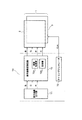
(Third embodiment of illumination device and liquid crystal device)
FIG. 14 shows still another embodiment of the illumination device and the liquid crystal device according to the present invention. In the previous embodiment described with reference to FIGS. 1 and 4 and the previous embodiment described with reference to FIGS. 1 and 12, as shown in FIG. A lighting device of a type provided on the side surface, a so-called sidelight type lighting device was used. In contrast, FIG.
The
本実施形態の照明装置53は、光反射板54と、光源部57と、光散乱板55と、第1
の集光板56aと、第2の集光板56bとを有する。光反射板54、光源部57、光散乱
板55、集光板56a、集光板56bの各要素は、図15に示すように、筐体59に互い
に重ねて収納される。そして、集光板56bの上に液晶パネル52が設けられる。液晶パ
ネル52としては、例えば、図1及び図2に示した液晶パネル2が用いられる。
The
The
光源部57は、図16(a)に示す短冊状すなわち単列の光源ユニット63を面内に複
数個、平行に並べることによって形成されている。個々の単列の光源ユニット63は、フ
レキシブル基板58と、その基板58上に設けられた複数の発光要素62とを有する。複
数の発光要素62は、個々のフレキシブル基板58上で直線の列状に並べられており、複
数のフレキシブル基板58を平行に並べたときに縦方向及び横方向へマトリクス状に並べ
られる。発光要素62としては、光源ユニットとしての白色光源62Wと、単色光源とし
てのシアン色LED62Cの2種類が用いられている。白色光源62Wは、図17(a)
及び図17(b)に示すように、青色LED32BとYAG蛍光体42とを有する白色光
源となっている。図17(a)及び図17(b)において図5と同じ符号は同じ部材を示
している。
The
And as shown in FIG.17 (b), it is the white light source which has blue LED32B and the
白色光源62Wのスペクトルは、例えば、図6に示す特性とされる。また、シアン色L
ED62Cは、そのスペクトルが、例えば、図7に示すようにシアンの波長部分Wcにピ
ークを有するものが用いられる。このシアンの波長部分Wcは、本実施形態で用いるカラ
ーフィルタにおいてシアンの着色膜21Cが有するスペクトルピーク波長とほぼ同じであ
る。白色光源62Wは、出射光がスペクトル上で2つのピークを持つ光源ユニットである
。また、シアン色LED62Cは、それらの2つのピークの少なくとも一方の谷に相当す
る波長部分にピークを持つ単色光源である。
The spectrum of the
As the ED62C, one having a spectrum with a peak in the cyan wavelength portion Wc as shown in FIG. 7, for example, is used. The cyan wavelength portion Wc is substantially the same as the spectral peak wavelength of the cyan colored film 21C in the color filter used in this embodiment. The
複数個の白色光源62Wと複数個のシアン色LED62Cとの配列の仕方に関しては、
例えば、図16(a)の例では、白色光源62Wとシアン色LED62Cとが行方向Xに
1つずつ交互に並び、単色光源であるシアン色LED62Cは行方向X及び列方向Yの両
方向で互いに隣り同士に並ばない配列状態である。複数の単色光源を互いに隣り同士に並
ばないように配列すれば、複数の単色光源が互いに隣り同士に並ぶ場合に比べて、光源ユ
ニットから出射される白色光と単色光源から出射されるシアン色光との混光をより一層促
進できる。
Regarding the arrangement of the plurality of
For example, in the example of FIG. 16A, the
本実施形態の液晶装置51においては、表示を行う際、例えば図11(b)に示すよう
に白色光源62Wとシアン色LED62Cとが1フレーム期間中の所定期間だけパルス幅
制御によって発光する。これにより、図14の照明装置53から面状の光が液晶パネル5
2へ直接に照射される。本実施形態の場合、B,G,R,Cの4色の着色膜21(図1参
照)を有するカラーフィルタのスペクトルは図3に示すようにB,G,Rのそれぞれの波
長部分Wb,Wg,Wrにピークを有する以外にシアンに対応する波長部分Wcにもピー
クを有している。このカラーフィルタに対して従来のような図6に示すスペクトル、すな
わちWbとWyの2つのピークしか持たない白色光源によって照明光を供給することにす
れば、図3のシアン色部分Wcが暗くなって良好な表示品質が得られないおそれがある。
これに対し、図16(a)において白色光源62Wに加えて単色光源であるシアン色LE
D62Cを設けることにより、図7に示すように2つのピークWb及びWyの谷に相当す
る波長部分であるWcにピークを有する光を形成して、その光をカラーフィルタへ供給す
ることにすれば、シアン色部分の輝度を向上でき、そのため、実質的な光透過率を向上さ
せることができる。
In the
2 is directly irradiated. In the case of the present embodiment, the spectrum of the color filter having the four color films 21 (see FIG. 1) of B, G, R, and C is shown in FIG. In addition to having peaks at Wg and Wr, the wavelength portion Wc corresponding to cyan also has a peak. If the illumination light is supplied to the color filter by a conventional white light source having the spectrum shown in FIG. 6, that is, only two peaks of Wb and Wy, the cyan portion Wc in FIG. 3 becomes dark. Therefore, there is a possibility that good display quality cannot be obtained.
On the other hand, in FIG. 16A, in addition to the
By providing D62C, as shown in FIG. 7, light having a peak at Wc, which is a wavelength portion corresponding to two peaks Wb and a valley of Wy, is formed, and the light is supplied to the color filter. The luminance of the cyan color portion can be improved, and therefore the substantial light transmittance can be improved.
(変形例)
図16(a)に示した例では、白色光源62Wとシアン色LED62Cとを行方向Xで
1つずつ交互に並べ、且つ列方向Yではシアン色LED62Cが隣り合わないようにした
。この配列態様に代えて、図16(b)に示す配列態様を採用することもできる。この配
列態様では、行方向Xに沿って、1個のシアン色LED62Cに対して白色光源62Wを
2個設けている。また、列方向Yに関しては、シアン色LED62Cが互いに隣り合わな
いように配列されている。白色光源62W及びシアン色LED62Cの両方が発光すると
、図16(c)に示すように、各素子62W,62Cから所定の角度範囲で光が広がった
状態で出射され、適宜の距離だけ進行した後にYAG蛍光光とシアン色光との間で混光が
生じて白色光が形成される。なお、図16(a)及び図16(b)において、混光の程度
を高めるために、複数の単列の光源ユニット63内における白色光源62Wとシアン色L
ED62Cの配置の順番を変えても良い。
(Modification)
In the example shown in FIG. 16A, the
The order of arrangement of the ED62C may be changed.
(電子機器の実施形態)
次に、本発明に係る電子機器の実施形態を説明する。図18は電子機器の一実施形態の
ブロック図を示している。ここに示す電子機器は、液晶装置1と、制御回路70とを有す
る。液晶装置1は図1及び図2に示した液晶装置1と同じ構成の液晶装置であり、液晶パ
ネル2と照明装置3とを有している。
(Embodiment of electronic device)
Next, an embodiment of an electronic device according to the present invention will be described. FIG. 18 shows a block diagram of an embodiment of an electronic device. The electronic apparatus shown here includes the
制御回路70は、表示画像出力源71と、表示画像変換回路72と、タイミングジェネ
レータ73とを有する。液晶装置1において、入力されたB,G,Rの各色の画像信号が
B,G,R,Cの各色の画像信号に変換される場合、表示画像変換回路72は、表示画像
出力源71から出力されたB,G,Rの各色の画像信号を、B,G,R,Cの各色の画像
信号に変換して、液晶パネル2へ出力する機能を有する。
The
表示画像変換回路72は、CPU(Central Processing Unit)等といった演算処理部
72aと、RAM(Random Access Memory)等といった記憶部72bとを有する。演算処
理部72aは、表示画像出力源71から出力された入力画像のB,G,Rの各色の画像信
号を、B,G,R,Cの各色の画像信号に変換する。記憶部72bには、所定の強度のB
,G,Rの各色の画像信号と、これに対応する強度のB,G,R,Cの各色の画像信号と
を対応させたLUT(Look Up Table)が格納されている。
The display
, G, R color image signals and B, G, R, C color image signals with corresponding intensities are stored in an LUT (Look Up Table).
例えば、演算処理部72aに、シアンCの色のみを表示させるB,G,Rの各色の画像
信号、例えばB=100、G=100、R=0の強度のB,G,Rの各色の画像信号が入
力された場合、演算処理部72aは、このB,G,Rの各色の画像信号の強度に対応する
強度のB,G,R,Cの各色の画像信号(たとえば、B=10、G=10、R=0、C=
100)を、記憶部72bのLUTから取得し、取得したB,G,Rの各色の画像信号を
液晶パネル2へ出力する。これにより、液晶パネル2の表示画面に、B,G,Rの各色に
加えてCの色を表示できる。これにより、入力画像の画像信号として、B,G,Rの画像
信号が入力された場合においても、出力画像の色再現範囲をシアン系色の色再現範囲まで
拡大できる。
For example, image signals of B, G, and R colors for displaying only cyan C color on the
100) is acquired from the LUT in the
タイミングジェネレータ73は、タイミングモードを切り替えるためのハードスイッチ
又はソフトスイッチを有し、画像信号の輝度信号からクロック信号CLKを生成する。図
9のLED駆動回路47,48は、タイミングジェネレータ73によって決定されたクロ
ック信号CLKに適合するように、駆動シーケンスが制御される。
The
図19は、本発明に係る電子機器の他の一実施形態であるパーソナルコンピュータを示
している。このパーソナルコンピュータ80は、表示装置として機能する液晶装置81と
、本体部82とを有する。本体部82にはキーボード83が設けられている。液晶装置8
1は、図1に示した液晶装置1や、図14に示した液晶装置51とすることができる。明
るい表示を希望する場合には、図1に示すサイドライト方式の液晶装置1よりも、図14
に示す平面ライト方式の液晶装置51を用いることが望ましい。
FIG. 19 shows a personal computer which is another embodiment of the electronic apparatus according to the invention. The
1 may be the
It is desirable to use the flat light type
図20は、本発明に係る電子機器の他の実施形態である携帯電話機を示している。ここ
に示す携帯電話機90は、本体部92と、これに開閉可能に設けられた表示体部93とを
有する。表示体部93には、液晶装置91が表示装置として設けられている。液晶装置9
1は、図1に示した液晶装置1や、図14に示した液晶装置51とすることができる。携
帯電話機90を小型にしたい場合には、図14に示す平面ライト方式の液晶装置51より
も、図1に示すサイドライト方式の液晶装置1を用いることが望ましい。
FIG. 20 shows a mobile phone which is another embodiment of the electronic apparatus according to the invention. A
1 may be the
本体部92には操作ボタン94及び送話部95が設けられている。送話部95の内部に
は、図示しないマイクが内蔵されている。表示体部93の一部にはアンテナ96が伸縮自
在に取り付けられている。表示体部93の上部に設けられた受話部97の内部には、図示
しないスピーカが配置される。液晶装置91の動作を制御するための制御部は、携帯電話
機全体の制御を司る制御部の一部として、又はその制御部とは別に、本体部92又は表示
体部93の内部に格納されている。
The
本発明に係る液晶装置1(図1参照)、液晶装置51(図14参照)等によれば、広い
色度域を持った表示を行うことができるので、それらの液晶装置を用いて構成された上記
の各電子機器においても、広い色度域を持った表示を行うことができる。
According to the liquid crystal device 1 (see FIG. 1), the liquid crystal device 51 (see FIG. 14), and the like according to the present invention, a display having a wide chromaticity range can be performed. In each of the above electronic devices, display with a wide chromaticity range can be performed.
(変形例)
本発明は、図19に示すパーソナルコンピュータや図20に示す携帯電話機以外の他の
電子機器に適用できる。例えば、本発明は、液晶テレビ、ビューファインダ型又はモニタ
直視型のビデオテープレコーダ、カーナビゲーション装置、ページャ、電子手帳、電卓、
ワードプロセッサ、ワークステーション、テレビ電話、POS端末、デジタルスチルカメ
ラ等といった各種の電子機器に適用できる。
(Modification)
The present invention can be applied to other electronic devices other than the personal computer shown in FIG. 19 and the mobile phone shown in FIG. For example, the present invention includes a liquid crystal television, a viewfinder type or a monitor direct-view type video tape recorder, a car navigation device, a pager, an electronic notebook, a calculator,
The present invention can be applied to various electronic devices such as word processors, workstations, videophones, POS terminals, digital still cameras, and the like.
1,51.液晶装置、 2,52.液晶パネル、 3,53.照明装置、
4.素子基板、 4a.透光性基板、 5.カラーフィルタ基板、 5a.透光性基板、
7.シール材、 8.液晶層、 9a,9b.偏光板、 11.ソース線、
12.ゲート線、 2a.引回し配線、 13.TFT素子、 14.画素電極、
15.張出し部、 16.外部接続用端子、 17.駆動用IC、 18.FPC基板、
21.着色膜、 22.オーバーコート膜、 23.共通電極、 24.配線、
26.導光体、 27A,27B,57.光源部、 28,58.フレキシブル基板、
29A,29B.光源ユニット、 31.絶縁基板、
32B.青色LED(発光素子)、 32C.シアン色LED(単色光源)、
33,34.電極、 36.アノード、 37a,37b.ワイヤ、 38.カソード、
39.絶縁体、 41.透明樹脂、 42.YAG系蛍光体、 44.駆動回路、
49.パルス電圧発生回路、 54.光反射板、 55.光散乱板、
56a,56b.集光板、 59.筐体、 62.発光要素、 62W.白色光源、
62C.シアン色LED、 63.単列の光源ユニット、 70.制御回路、
80.パーソナルコンピュータ(電子機器)、 81.液晶装置、
90.携帯電話機(電子機器)、 91.液晶装置、 C.隅の領域、 D.サブ画素、
F.額縁領域、 G.表示画素、 R0.電流制限抵抗、 V.表示領域
1,51. Liquid crystal device, 52. Liquid crystal panel, 3,53. Lighting equipment,
4). Element substrate, 4a. 4. a translucent substrate; Color filter substrate, 5a. Translucent substrate,
7). Seal material, 8. Liquid crystal layer, 9a, 9b. 10. polarizing plate; Source line,
12 Gate lines, 2a. 12. Lead wiring, TFT element, 14. Pixel electrodes,
15. Overhang part, 16. 16. External connection terminal Driving IC, 18. FPC board,
21. Colored film, 22. Overcoat film, 23. Common electrode, 24. wiring,
26. Light guide, 27A, 27B, 57.
29A, 29B. Light source unit, 31. Insulating substrate,
32B. Blue LED (light emitting element), 32C. Cyan LED (single color light source),
33, 34. Electrodes, 36. Anode, 37a, 37b. Wire, 38. Cathode,
39. Insulators, 41. Transparent resin, 42. YAG phosphor, 44. Drive circuit,
49. Pulse voltage generation circuit, 54. Light reflector, 55. Light scattering plate,
56a, 56b. Light collector, 59. Housing, 62. Light emitting element, 62W. White light source,
62C. 63.
80. 81. personal computer (electronic equipment) Liquid crystal device,
90. Mobile phone (electronic device), 91. Liquid crystal device, C.I. C. corner area Sub-pixel,
F. Frame region, G. Display pixels, R0. Current limiting resistor; Indicated Area
Claims (14)
ークの少なくとも一方の谷に相当する波長部分にピークを持つ単色光源とを有することを
特徴とする照明装置。 An illumination apparatus comprising: a light source unit having emitted light having at least two peaks in the spectrum; and a monochromatic light source having a peak in a wavelength portion corresponding to at least one valley of the two peaks.
ことを特徴とする照明装置。 The lighting device according to claim 1, wherein the monochromatic light source is included in the light source unit.
とを特徴とする照明装置。 2. The illumination device according to claim 1, wherein the monochromatic light source is separate from the light source unit.
、
第1の発光ダイオードと、
該第1の発光ダイオードの出射光を吸収して当該出射光の補色となる出射光を発光する
蛍光体と、
を有することを特徴とする照明装置。 The illuminating device according to any one of claims 1 to 3, wherein the light source unit is
A first light emitting diode;
A phosphor that absorbs light emitted from the first light emitting diode and emits light that is complementary to the light emitted;
A lighting device comprising:
装置。 5. The lighting device according to claim 4, wherein the monochromatic light source is a second light emitting diode.
白色光を出射することを特徴とする照明装置。 6. The illumination device according to claim 1, wherein the light source unit emits white light.
前記第1の発光ダイオードは青色光を出射する発光ダイオードであり、
前記蛍光体はYAG(イットリウム・アルミニウム・ガーネット)系の蛍光体であり、
前記単色光源はシアン(青緑)色光を出射する光源である
ことを特徴とする照明装置。 In the illuminating device as described in any one of Claims 4-6,
The first light emitting diode is a light emitting diode that emits blue light;
The phosphor is a YAG (yttrium, aluminum, garnet) phosphor,
The illumination device according to claim 1, wherein the monochromatic light source is a light source that emits cyan (blue-green) color light.
前記第1の発光ダイオードは青色光を出射する発光ダイオードであり、
前記蛍光体はYAG系の蛍光体であり、
前記単色光源は緑色光を出射する光源である
ことを特徴とする照明装置。 In the illuminating device as described in any one of Claims 4-6,
The first light emitting diode is a light emitting diode that emits blue light;
The phosphor is a YAG phosphor,
The illumination device according to claim 1, wherein the monochromatic light source is a light source that emits green light.
前記第1の発光ダイオードは青色光を出射する発光ダイオードであり、
前記蛍光体はYAG系の蛍光体であり、
前記単色光源は赤色光を出射する光源である
ことを特徴とする照明装置。 In the illuminating device as described in any one of Claims 4-6,
The first light emitting diode is a light emitting diode that emits blue light;
The phosphor is a YAG phosphor,
The monochromatic light source is a light source that emits red light.
前記光源ユニット及び前記単色光源はそれぞれ複数個が平面的に並べられ、
前記複数の単色光源は隣り同士には並ばない
ことを特徴とする照明装置。 In the illuminating device as described in any one of Claims 1-9,
A plurality of the light source units and the monochromatic light sources are arranged in a plane,
The lighting device, wherein the plurality of monochromatic light sources are not arranged next to each other.
て照明される被照明体は複数色の着色膜を有するカラーフィルタである照明装置において
、
前記単色光源の出射光の波長は前記カラーフィルタのスペクトルに含まれるピークの波
長とほぼ一致する
ことを特徴とする照明装置。 The illumination device according to any one of claims 1 to 10, wherein an object to be illuminated illuminated by the illumination device is a color filter having a colored film of a plurality of colors.
The illumination device according to claim 1, wherein the wavelength of the emitted light of the monochromatic light source substantially coincides with a peak wavelength included in a spectrum of the color filter.
明装置は請求項1から請求項10のいずれか1つに記載の照明装置であることを特徴とす
る液晶装置。 A liquid crystal device having a liquid crystal panel and an illuminating device that illuminates the liquid crystal panel, wherein the illuminating device is the illuminating device according to any one of claims 1 to 10.
有し、前記単色光源の出射光の波長は前記カラーフィルタのスペクトルに含まれるピーク
の波長とほぼ一致することを特徴とする液晶装置。 13. The liquid crystal device according to claim 12, further comprising a color filter having a colored film of a plurality of colors, wherein the wavelength of the emitted light of the monochromatic light source substantially coincides with the peak wavelength included in the spectrum of the color filter. A liquid crystal device.
An electronic apparatus comprising the liquid crystal device according to claim 12.
Priority Applications (1)
| Application Number | Priority Date | Filing Date | Title |
|---|---|---|---|
| JP2006110915A JP2007287385A (en) | 2006-04-13 | 2006-04-13 | Lighting device, liquid crystal device, and electronic device |
Applications Claiming Priority (1)
| Application Number | Priority Date | Filing Date | Title |
|---|---|---|---|
| JP2006110915A JP2007287385A (en) | 2006-04-13 | 2006-04-13 | Lighting device, liquid crystal device, and electronic device |
Publications (1)
| Publication Number | Publication Date |
|---|---|
| JP2007287385A true JP2007287385A (en) | 2007-11-01 |
Family
ID=38758983
Family Applications (1)
| Application Number | Title | Priority Date | Filing Date |
|---|---|---|---|
| JP2006110915A Withdrawn JP2007287385A (en) | 2006-04-13 | 2006-04-13 | Lighting device, liquid crystal device, and electronic device |
Country Status (1)
| Country | Link |
|---|---|
| JP (1) | JP2007287385A (en) |
Cited By (8)
| Publication number | Priority date | Publication date | Assignee | Title |
|---|---|---|---|---|
| JP2009300955A (en) * | 2008-06-17 | 2009-12-24 | Toppan Printing Co Ltd | Color filter and liquid crystal display device |
| WO2011114374A1 (en) * | 2010-03-17 | 2011-09-22 | Necディスプレイソリューションズ株式会社 | Backlight device, method of driving backlight device |
| JP2012069572A (en) * | 2010-09-21 | 2012-04-05 | Panasonic Corp | Light-emitting module, backlight device and display device |
| JP2016162829A (en) * | 2015-02-27 | 2016-09-05 | 日亜化学工業株式会社 | Light emitting device |
| JP2016164881A (en) * | 2015-03-06 | 2016-09-08 | 三星ディスプレイ株式會社Samsung Display Co.,Ltd. | Display device |
| JP2017152666A (en) * | 2016-02-25 | 2017-08-31 | 豊田合成株式会社 | Light-emitting device |
| JP2018056359A (en) * | 2016-09-29 | 2018-04-05 | 豊田合成株式会社 | Light-emitting device and manufacturing method therefor |
| JP2022500841A (en) * | 2018-09-19 | 2022-01-04 | オスラム オーエルイーディー ゲゼルシャフト ミット ベシュレンクテル ハフツングOSRAM OLED GmbH | Light emitting element |
-
2006
- 2006-04-13 JP JP2006110915A patent/JP2007287385A/en not_active Withdrawn
Cited By (12)
| Publication number | Priority date | Publication date | Assignee | Title |
|---|---|---|---|---|
| JP2009300955A (en) * | 2008-06-17 | 2009-12-24 | Toppan Printing Co Ltd | Color filter and liquid crystal display device |
| WO2011114374A1 (en) * | 2010-03-17 | 2011-09-22 | Necディスプレイソリューションズ株式会社 | Backlight device, method of driving backlight device |
| JP5327925B2 (en) * | 2010-03-17 | 2013-10-30 | Necディスプレイソリューションズ株式会社 | Backlight device and driving method of backlight device |
| JP2012069572A (en) * | 2010-09-21 | 2012-04-05 | Panasonic Corp | Light-emitting module, backlight device and display device |
| JP2016162829A (en) * | 2015-02-27 | 2016-09-05 | 日亜化学工業株式会社 | Light emitting device |
| JP2016164881A (en) * | 2015-03-06 | 2016-09-08 | 三星ディスプレイ株式會社Samsung Display Co.,Ltd. | Display device |
| CN105938707A (en) * | 2015-03-06 | 2016-09-14 | 三星显示有限公司 | Display apparatus |
| CN105938707B (en) * | 2015-03-06 | 2020-08-14 | 三星显示有限公司 | display device |
| JP2017152666A (en) * | 2016-02-25 | 2017-08-31 | 豊田合成株式会社 | Light-emitting device |
| JP2018056359A (en) * | 2016-09-29 | 2018-04-05 | 豊田合成株式会社 | Light-emitting device and manufacturing method therefor |
| JP2022500841A (en) * | 2018-09-19 | 2022-01-04 | オスラム オーエルイーディー ゲゼルシャフト ミット ベシュレンクテル ハフツングOSRAM OLED GmbH | Light emitting element |
| JP7254906B2 (en) | 2018-09-19 | 2023-04-10 | オスラム オーエルイーディー ゲゼルシャフト ミット ベシュレンクテル ハフツング | light emitting element |
Similar Documents
| Publication | Publication Date | Title |
|---|---|---|
| US7530722B2 (en) | Illumination device, electro-optical device, and electronic apparatus | |
| CN1700265B (en) | Display device, color filter and electronic equipment | |
| CN100432771C (en) | Electro-optical devices and electronic equipment | |
| JP4424297B2 (en) | LIGHT EMITTING DEVICE, LIGHTING DEVICE, ELECTRO-OPTICAL DEVICE, AND ELECTRONIC DEVICE | |
| WO2014087875A1 (en) | Display device and television reception device | |
| WO2014141879A1 (en) | Display device and television reception device | |
| JP2007109617A (en) | LIGHT EMITTING DEVICE, LIGHTING DEVICE, ELECTRO-OPTICAL DEVICE, AND ELECTRONIC DEVICE | |
| WO2013191094A1 (en) | Display device and television receiver | |
| CN100405195C (en) | Liquid crystal display device and electronic equipment | |
| JP2007287384A (en) | Lighting device, liquid crystal device, and electronic device | |
| JP2007287385A (en) | Lighting device, liquid crystal device, and electronic device | |
| US20070085804A1 (en) | Driving circuit for electro-optical device and electronic apparatus | |
| US11194090B2 (en) | Display device | |
| JP2008139528A (en) | Electro-optical device and electronic appliance | |
| KR101946263B1 (en) | Liquid crystal display device | |
| JP2017073412A (en) | Display device and light source device | |
| JP2007287789A (en) | LIGHTING DEVICE, LIQUID CRYSTAL DEVICE, AND ELECTRONIC DEVICE | |
| JP2007279197A (en) | Liquid crystal device and electronic equipment | |
| JP2007114276A (en) | LIGHTING DEVICE, ELECTRO-OPTICAL DEVICE, AND ELECTRONIC DEVICE | |
| KR101683874B1 (en) | Display device | |
| JP2006317823A (en) | Display and electronic equipment | |
| KR20090054840A (en) | Backlight and liquid crystal display device having same | |
| US20050243048A1 (en) | Display device, and electronic apparatus | |
| JP2007279176A (en) | Liquid crystal device and electronic equipment | |
| JP2009204899A (en) | Electrooptical device, elecronic equipment and driving method of electrooptical device |
Legal Events
| Date | Code | Title | Description |
|---|---|---|---|
| A300 | Application deemed to be withdrawn because no request for examination was validly filed |
Free format text: JAPANESE INTERMEDIATE CODE: A300 Effective date: 20090707 |