JP2006106484A - Focus detection method - Google Patents
Focus detection method Download PDFInfo
- Publication number
- JP2006106484A JP2006106484A JP2004295044A JP2004295044A JP2006106484A JP 2006106484 A JP2006106484 A JP 2006106484A JP 2004295044 A JP2004295044 A JP 2004295044A JP 2004295044 A JP2004295044 A JP 2004295044A JP 2006106484 A JP2006106484 A JP 2006106484A
- Authority
- JP
- Japan
- Prior art keywords
- contrast
- peak
- focus
- focus detection
- value
- Prior art date
- Legal status (The legal status is an assumption and is not a legal conclusion. Google has not performed a legal analysis and makes no representation as to the accuracy of the status listed.)
- Pending
Links
Images


Classifications
-
- H—ELECTRICITY
- H04—ELECTRIC COMMUNICATION TECHNIQUE
- H04N—PICTORIAL COMMUNICATION, e.g. TELEVISION
- H04N23/00—Cameras or camera modules comprising electronic image sensors; Control thereof
- H04N23/60—Control of cameras or camera modules
- H04N23/67—Focus control based on electronic image sensor signals
- H04N23/673—Focus control based on electronic image sensor signals based on contrast or high frequency components of image signals, e.g. hill climbing method
-
- H—ELECTRICITY
- H04—ELECTRIC COMMUNICATION TECHNIQUE
- H04N—PICTORIAL COMMUNICATION, e.g. TELEVISION
- H04N25/00—Circuitry of solid-state image sensors [SSIS]; Control thereof
- H04N25/10—Circuitry of solid-state image sensors [SSIS]; Control thereof for transforming different wavelengths into image signals
- H04N25/11—Arrangement of colour filter arrays [CFA]; Filter mosaics
- H04N25/13—Arrangement of colour filter arrays [CFA]; Filter mosaics characterised by the spectral characteristics of the filter elements
- H04N25/134—Arrangement of colour filter arrays [CFA]; Filter mosaics characterised by the spectral characteristics of the filter elements based on three different wavelength filter elements
Landscapes
- Engineering & Computer Science (AREA)
- Multimedia (AREA)
- Signal Processing (AREA)
- Physics & Mathematics (AREA)
- Spectroscopy & Molecular Physics (AREA)
- Focusing (AREA)
- Automatic Focus Adjustment (AREA)
- Studio Devices (AREA)
Abstract
【課題】低コントラストの被写体であっても、合焦外れが少ない焦点検出方法を提供する。
【解決手段】複数の焦点検出エリア内の被写体像のコントラストに基づいて焦点状態を検出する焦点検出方法であって、撮影レンズの焦点調節レンズ群を調節可動範囲内において段階的に移動させながら撮像し、撮像した各焦点検出エリア内の被写体像のコントラストを求め、焦点検出エリア毎に、焦点調節レンズ移動方向におけるコントラストから所定の信頼性条件を満たすピークコントラストを検出し、所定の信頼性条件を満たすピークコントラストが検出できなかった場合は、所定の信頼性条件を満たすピークコントラストが検出できなかった場合は、所定数以上の焦点検出エリアにおける同一または所定範囲内の焦点調節レンズ位置において検出されたピークコントラストを選択する。
【選択図】 図8Provided is a focus detection method with little defocusing even for a low-contrast subject.
A focus detection method for detecting a focus state based on the contrast of subject images in a plurality of focus detection areas, wherein imaging is performed while a focus adjustment lens group of a photographing lens is moved stepwise within an adjustment movable range. The contrast of the captured subject image in each focus detection area is obtained, and for each focus detection area, the peak contrast satisfying a predetermined reliability condition is detected from the contrast in the moving direction of the focus adjustment lens, and the predetermined reliability condition is set. If the peak contrast that satisfies the condition is not detected, or if the peak contrast that satisfies the predetermined reliability condition cannot be detected, the peak contrast is detected at the same or in a predetermined range of focus adjustment lens positions in the focus detection area. Select the peak contrast.
[Selection] Figure 8
Description
本発明は、撮像した画像データのコントラストを使用して焦点を検出する焦点検出方法に関する。 The present invention relates to a focus detection method for detecting a focus using the contrast of captured image data.
いわゆるコンパクトタイプのデジタルカメラの焦点調節方法として、撮像した画像データのコントラストにより焦点を検出する画像コントラスト法が知られている。画像コントラスト法による焦点調節装置は、焦点調節レンズ群を無限遠合焦位置と至近合焦位置との間を移動しながら撮像を繰り返して撮像した被写体像(画像データ)のコントラストがピークとなる焦点調節レンズ群の位置を求める。そのために従来の焦点調節装置は、焦点調節レンズ群を無限遠(最長)合焦位置から至近(最短)合焦位置までステップ移動しながら複数位置で撮像し、撮像した映像信号から各レンズ位置におけるコントラストを求め、さらにコントラストの極大値(ピーク値)を求めて、極大値が得られたレンズ位置を合焦点と判定してそのレンズ位置に焦点調節レンズ群を移動していた(特許文献1)。
しかし従来の画像コントラスト法において、被写体がローコントラストまたは暗くて複数のピークを検出した場合や、ピークを検出できなかった場合等、一つのピークを決定できなかった場合は、ストロボのオン/オフや、蛍光灯下であるか否か等で、仮想の合焦位置を決定していた。そのため、近距離のローコントラストの被写体の場合は大きく外れた距離に合焦されてしまう。被写体像を表示する液晶ディスプレイを備えたデジタルカメラの場合は、液晶ディスプレイに表示された被写体像がピンボケ過ぎることがあった。 However, in the conventional image contrast method, when the subject is low contrast or dark and a plurality of peaks are detected, or when no peak can be detected, the strobe can be turned on / off, The virtual in-focus position is determined by whether or not it is under a fluorescent lamp. For this reason, in the case of a low-contrast subject at a short distance, the subject is focused at a far off distance. In the case of a digital camera including a liquid crystal display that displays a subject image, the subject image displayed on the liquid crystal display may be too out of focus.
本発明は、かかる従来の画像コントラスト式の焦点検出方法の問題に鑑みてなされたもので、低コントラストの被写体であっても、合焦外れが少ない焦点検出方法を提供することを目的とする。 The present invention has been made in view of the problem of the conventional image contrast type focus detection method, and an object of the present invention is to provide a focus detection method with little defocusing even for a low-contrast subject.
この目的を達成する本発明は、複数の焦点検出エリア内の被写体像のコントラストに基づいて焦点状態を検出する焦点検出方法であって、撮影レンズの焦点調節レンズ群を調節可動範囲内において段階的に移動させながら撮像し、撮像した各焦点検出エリア内の被写体像のコントラストを求め、焦点検出エリア毎に、焦点調節レンズ移動方向におけるコントラストから所定の信頼性条件を満たすピークコントラストを検出し、所定の信頼性条件を満たすピークコントラストが検出できなかった場合は、所定の信頼性条件を満たすピークコントラストが検出できなかった場合は、所定数以上の焦点検出エリアにおける同一または所定範囲内の焦点調節レンズ位置において検出されたピークコントラストを選択すること、に特徴を有する。 The present invention that achieves this object is a focus detection method for detecting a focus state based on the contrasts of subject images in a plurality of focus detection areas, wherein the focus adjustment lens group of the photographing lens is stepped within an adjustable movable range. The contrast of the captured subject image in each focus detection area is obtained, and the peak contrast satisfying a predetermined reliability condition is detected from the contrast in the moving direction of the focus adjustment lens for each focus detection area. If no peak contrast satisfying the reliability condition is detected, or if a peak contrast satisfying the predetermined reliability condition cannot be detected, the focus adjustment lens in the same or a predetermined range in a predetermined number or more of focus detection areas It is characterized by selecting the peak contrast detected at the position.
前記信頼性条件は、前記検出したピークコントラストと、ピーク検出のために比較したコントラストとの差が所定値以上あること、その焦点検出エリアにおいて得られたコントラストの最低値との差が所定値以上あること、およびピークコントラストがその焦点検出エリアの最大値であることの、いずれか一つ以上から選択できる。 The reliability condition is that the difference between the detected peak contrast and the contrast compared for peak detection is a predetermined value or more, and the difference between the minimum value of the contrast obtained in the focus detection area is a predetermined value or more. It can be selected from any one or more of the existence and the peak contrast being the maximum value of the focus detection area.
コントラストのピークは、前記コントラストが焦点調節レンズ移動方向に沿って連続して2回増大しかつ2回連続して減少している場合の最大コントラストとすることができる。 The contrast peak may be the maximum contrast when the contrast increases twice continuously and decreases continuously twice along the moving direction of the focusing lens.
前記信頼性のあるコントラストが得られず、同一または所定範囲内の焦点調節レンズ位置における所定数以上のピークコントラストが、異なる焦点調節レンズ位置または所定範囲に存在したときは、最も近距離に相当する焦点調節レンズ位置または所定範囲のピークコントラストを選択する。 When the above-mentioned reliable contrast is not obtained and a peak contrast of a predetermined number or more at the same or within a predetermined range of focusing lens positions exists at different focusing lens positions or within a predetermined range, it corresponds to the shortest distance. Select a focus lens position or a predetermined range of peak contrast.
前記信頼性のあるコントラストが得られず、同一または所定範囲内の焦点調節レンズ位置における所定数以上のピークコントラストを選択したときは、選択した複数のピークコントラストから得られた焦点調節レンズ位置の平均位置を合焦レンズ位置として焦点調節する。 When the above-mentioned reliable contrast is not obtained and a peak contrast of a predetermined number or more at the same or within a predetermined range of focus adjustment lens positions is selected, the average of the focus adjustment lens positions obtained from a plurality of selected peak contrasts The focus is adjusted using the position as the focusing lens position.
本発明によれば、画像コントラスト法において所定の信頼性条件を満たすピークコントラストが検出できなかった場合は、各焦点検出エリア毎に得た、または各焦点検出エリア毎にピークコントラストを検出し、同一または所定範囲内の焦点調節レンズ位置において、所定数以上の焦点検出エリアで検出されたピークコントラストを選択するので、正確な合焦はできなくても大きく外れることはない。 According to the present invention, when the peak contrast satisfying the predetermined reliability condition cannot be detected in the image contrast method, the peak contrast obtained for each focus detection area or detected for each focus detection area is the same. Alternatively, since the peak contrast detected in a focus detection area of a predetermined number or more is selected at a focus adjustment lens position within a predetermined range, even if accurate focusing cannot be performed, it does not deviate greatly.
さらに請求項2記載発明によれば、焦点調節レンズ群を移動領域全域を移動させることなくコントラストのピークを検出できるので、焦点調節開始から合焦するまでの時間が短縮される。 Further, according to the second aspect of the present invention, since the peak of contrast can be detected without moving the focus adjustment lens group over the entire moving region, the time from the start of focus adjustment to focusing is shortened.
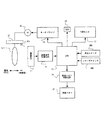
本発明の実施形態について、図を参照して説明する。図1は、本発明を適用したデジタルカメラの概要をブロックで示す図である。 Embodiments of the present invention will be described with reference to the drawings. FIG. 1 is a block diagram showing an outline of a digital camera to which the present invention is applied.
このデジタルカメラは、焦点調節レンズ群L1を含む撮影レンズLにより被写体像を、撮像手段としての撮像素子(CCDイメージセンサ)11の受光面に形成する。撮像素子11は、所定間隔で縦横に配置された多数の画素(光電変換素子)を有し、受光した被写体像を各画素が電荷に変換し、蓄積(積分)する。露光が終了すると、蓄積した電荷を画素単位で画像信号として画像信号処理回路13に出力する。画像信号処理回路13は、入力した画像信号についてホワイトバランス調整等所定の調整処理、A/D変換処理を施してデジタル映像データをCPU15に出力する。つまり、画像信号処理回路13において所定の処理が施され、画素単位でデジタル変換された画像データが、CPU15に出力される。CPU15は、スルーモード(モニタモード)のときは入力した画像データをLCD(モニタ)17で表示可能な画像信号に変換してLCD17により表示し、記録モードのときは所定フォーマットの画像データに変換して画像メモリ制御回路19を介して画像メモリ21に書き込む。図1において、符号29は合焦/非合焦表示用のLEDであって、例えば、合焦状態のときは緑色(青色)を点灯し、非合焦状態のときは緑色を点滅または赤色点灯する。
In this digital camera, a subject image is formed on a light receiving surface of an image pickup device (CCD image sensor) 11 as an image pickup means by a photographing lens L including a focus adjustment lens group L1. The
図2には、撮像素子の撮像面と焦点検出エリアとの一例として、撮像素子11の受光面12と、5個の焦点検出エリア12A、12B、12C、12D、12Eとの関係を示してある。図3は、中央の第1焦点検出エリア12Aを拡大して示した図である。第1焦点検出エリア12Aは受光面12のほぼ中央に位置し、第2、第3焦点検出エリア12B、12Cは、第1焦点検出エリア12Aを挟んで左右に位置し、第4、第5焦点検出エリア12D、12Eは第1焦点検出エリア12Aを挟んで上下に位置している。受光面12には、各画素(光電変換素子)より被写体側に、原色フィルタとしての赤(R)フィルタ、緑(G)フィルタおよび青(B)フィルタが配置されていて、各画素は、被写体光束中、各原色フィルタR、G、Bを透過した赤、緑および青成分を受光して光電変換し、電荷として蓄積(積分)する。所定時間蓄積した電荷は、画素単位で読み出され、画像信号として出力される。
FIG. 2 shows a relationship between the
図3には、一般的な原色フィルタの配置パターンを示してある。原色フィルタは、水平方向に、2種類のフィルタG、Rが交互に配置されたGRラインと、2種類のフィルタB、Gが交互に配置されたBGラインとを備え、GRラインとBGラインとが垂直方向に交互に配置されている。この実施形態では、水平方向2個分、垂直方向2個分(2×2)の正方形内の4画素、つまり2個のフィルタGと各1個のフィルタR、Bを含む計4画素の組み合わせを1ブロックとして、各ブロック内の画素が蓄積した画像信号の大きさの和を輝度anとする。
an= G + R + B + G
FIG. 3 shows a general primary color filter arrangement pattern. The primary color filter includes a GR line in which two types of filters G and R are alternately arranged in a horizontal direction and a BG line in which two types of filters B and G are alternately arranged. Are alternately arranged in the vertical direction. In this embodiment, four pixels in a square of two horizontal directions and two vertical directions (2 × 2), that is, a combination of four pixels including two filters G and one filter R and B each. as one block, the sum of the magnitudes of the image signals pixels in each block is stored as the brightness a n.
a n = G + R + B + G
そうして、1ブロックの輝度anと、水平方向に1ブロック飛ばした1ブロックの輝度an+2との差(an+2 - an)を求める処理を、焦点検出エリア内において水平右方向に繰り返し、輝度差(an+2 - an)を加算する。この輝度差(an+2 - an)を求める処理が水平方向右端のブロックに到達すると、垂直方向下方に1ブロックずらしてから輝度差を求める処理および加算処理を水平右方向に右端のブロックに達するまで繰り返す。以上の差の加算処理を、焦点検出エリア内の全ブロックについて繰り返し実行する。さらに同様の処理を、5個の焦点検出エリア12A乃至12Eそれぞれについて実行する。
Then, 1 and the brightness a n blocks, the difference between the brightness a n + 2 of one block of every other block in horizontal direction - the process of obtaining the (a n + 2 a n), horizontal in the focus detection area repeated in the right direction, the luminance difference - adding (a n + 2 a n) . The luminance difference - if (a n + 2 a n) processing of obtaining the reaches horizontally right end of the block, the process and the addition process obtains the brightness difference from shifting one block vertically downwards horizontally to right right edge of the block Repeat until you reach. The above difference addition processing is repeatedly executed for all blocks in the focus detection area. Further, similar processing is executed for each of the five
以上の処理によって得られる、各焦点検出エリア12A乃至12Eについて求めた輝度差(an+2 - an)の和がそのレンズ位置における各焦点検出エリア12A乃至12Eのコントラスト値になる。このコントラスト値は、下記数1式で現すことができる。
Obtained by the above process, the brightness difference obtained for each

この実施形態において、コントラストAF処理のときにCPU15は、モータドライバ23、AFモータ25、レンズ駆動機構27を介して焦点調節レンズ群L1をステップ駆動しながら撮像素子11により撮像し、撮像した画像信号中、予め設定された焦点検出エリア内の画像信号を入力して各焦点検出エリア内のコントラスト値を求め、コントラストデータとして内蔵RAMに記憶する。CPU15はこのコントラストAF処理を、焦点調節レンズ群L1を一方の移動限界位置である至近(最短)合焦位置から他方の移動限界位置である無限遠合焦位置方向にステップ駆動させながら繰り返す。
In this embodiment, during contrast AF processing, the
この実施形態では、焦点調節レンズ群L1の位置を、至近合焦位置を原点位置として原点センサ27aで検知し、原点からの駆動パルス数としてカウントする。駆動パルスは、例えばAFモータ25の出力軸に装着されたフォトインタラプタ等のエンコーダが出力するパルスとして定義する。なお、通常は、焦点調節レンズ群L1を至近合焦位置から無限遠合焦位置まで駆動するのに数百パルスあるいはそれ以上要するが、本実施形態におけるコントラストAF処理では、数パルスまたは数十パルス単位でステップ駆動(撮像)するものとし、本実施形態のコントラストAF処理における駆動パルスは、フォトインタラプタが出力する複数パルスを1パルスとする。
In this embodiment, the position of the focus adjustment lens group L1 is detected by the
至近(最短)合焦位置から無限遠合焦位置までの複数位置におけるコントラストデータが得られたら、焦点調節レンズ群L1の移動方向、例えば近距離側から遠距離側に連続した複数位置におけるコントラストデータを隣同士で順番に比較し、コントラスト値が所定回連続して増大し、かつ所定回連続して減少しているかどうか、つまりピークがあるかどうかを判定する。本実施形態では、近距離側または遠距離側から順に5位置分のコントラストデータに基づいて、コントラスト値が2回連続して増加しかつ2回連続して減少しているかどうか判定する。かかる判定を、1個分ずつ遠距離側または近距離側にずらせながら5個分のコントラストデータについて繰り返し実施する。2回連続して増大しかつ2回連続して減少している場合は、信頼性が高いかどうかを判定して、信頼性が高い場合のみ、ピークコントラストとする。 When contrast data is obtained at a plurality of positions from the closest (shortest) in-focus position to the infinity in-focus position, the contrast data at a plurality of positions in the moving direction of the focus adjustment lens group L1, for example, from the near distance side to the far distance side, is obtained. Are sequentially compared with each other, and it is determined whether the contrast value is continuously increased a predetermined number of times and continuously decreased a predetermined number of times, that is, whether there is a peak. In the present embodiment, based on the contrast data for five positions in order from the short distance side or the long distance side, it is determined whether or not the contrast value has been increased twice and continuously decreased. Such determination is repeatedly performed for five pieces of contrast data while shifting one by one to the far distance side or the short distance side. When it increases twice and decreases continuously twice, it is determined whether or not the reliability is high, and the peak contrast is set only when the reliability is high.
さらに本発明の実施形態では、信頼性が高いピークコントラストが無かった場合は、前記同様に、近距離側または遠距離側から順に5位置分のコントラストデータに基づいて、コントラスト値が2回連続して増加しかつ2回連続して減少しているかどうか判定して、ピークを検出する。そうして、全てのエリアについて求めたピークコントラストの内、同一のレンズ位置におけるピークコントラストが所定数以上存在するレンズ位置を検出する。そうして、それぞれのピークコントラストを挟むコントラストデータから近似演算をしてより正確なレンズ位置を求め、それらの平均のレンズ位置に焦点調節レンズ群L1を移動する。そうして、LED29を非合焦点灯する。
Furthermore, in the embodiment of the present invention, when there is no peak contrast with high reliability, the contrast value is continuously repeated twice based on the contrast data for five positions in order from the short distance side or the long distance side as described above. The peak is detected by determining whether it has increased and decreased continuously twice. Thus, a lens position where a predetermined number or more of peak contrasts at the same lens position exists among the peak contrasts obtained for all areas is detected. Then, approximate calculation is performed from the contrast data sandwiching each peak contrast to obtain a more accurate lens position, and the focus adjustment lens group L1 is moved to the average lens position thereof. Then, the
このように本実施形態では、信頼性の高いピークコントラストを検出できなかった場合は、信頼性にかかわらずピークコントラストを求め、同一のレンズ位置において所定数以上のピークコントラストが存在した場合に、そのレンズ位置または近傍に合焦点があるとして処理することに特徴の一つがある。 As described above, in this embodiment, when the peak contrast with high reliability cannot be detected, the peak contrast is obtained regardless of the reliability, and when a predetermined number or more of peak contrasts exist at the same lens position, One of the features is that processing is performed assuming that the focal point is at or near the lens position.
以下、本発明のコントラストAF処理の実施形態について、さらに図4から図10に示したフローチャートおよび図11に示したコントラストとレンズ位置との関係に関するグラフ、図12に示したレンズ位置パルス数とピーク数との関係およびエリアとピーク数との関係に関する表(A)、(B)、図13に示した直線近似グラフを参照して詳細に説明する。この実施形態は、測光スイッチSWSがオンしたときに、このフローチャートに入り、コントラストAF処理を1回実行する、いわゆるワンショットAFとする。 Hereinafter, with respect to the embodiment of the contrast AF processing of the present invention, the flowcharts shown in FIGS. 4 to 10 and the graph relating to the relationship between the contrast and the lens position shown in FIG. 11, the lens position pulse number and the peak shown in FIG. A detailed description will be given with reference to tables (A) and (B) relating to the relationship between the numbers and the relationship between the area and the number of peaks, and the linear approximation graph shown in FIG. In this embodiment, when the photometry switch SWS is turned on, this flowchart is entered, and the contrast AF process is executed once, so-called one-shot AF.
コントラストAF処理に入ると、まず各変数等の初期化を実行する(S11)。例えばこの実施形態では、各ステータスのクリア、コントラスト値のクリア、レンズ位置PNの初期化(PN = 0)、コントラストの最大値 = 0、最小値 = FFFFFFFF、焦点距離によるエリア数設定等を実行する。ここでレンズ位置PNは、焦点調節レンズ群L1が至近合焦位置にあるときを0として、無限遠合焦位置方向に、1パルス分移動する毎に1カウントアップされる変数である。
なお、焦点距離によるエリア数とは、焦点距離に応じて予め設定された、コントラスト値を算出するエリア数である。
When the contrast AF process is started, initialization of variables and the like is first executed (S11). For example, in this embodiment, clearing of each status, clearing of the contrast value, initialization of the lens position PN (PN = 0), maximum value of contrast = 0, minimum value = FFFFFFFF, setting of the number of areas by focal length, etc. are executed. . Here, the lens position PN is a variable that is incremented by 1 every time it moves by one pulse in the direction of the infinite focus position, with 0 when the focusing lens group L1 is at the closest focus position.
The number of areas based on the focal length is the number of areas for which a contrast value is calculated in advance according to the focal length.
フォーカスイニシャライズ処理を実行する(S13)。フォーカスイニシャライズ処理とは、焦点調節レンズ群L1を一方の移動限界位置、本実施形態では至近合焦位置まで移動することである。焦点調節レンズ群L1が至近合焦位置に移動したことは、原点センサ27aによって検知する。
A focus initialization process is executed (S13). The focus initialization process is to move the focus adjustment lens unit L1 to one movement limit position, in this embodiment, the closest focus position. The
そうして、現在の焦点レンズ群位置である至近合焦位置におけるコントラスト値算出処理を実行する(S15)。つまり、撮像素子11から入力した画像データに基づいて、至近合焦位置におけるコントラスト値P[0]を算出し、コントラストの最大値、最小値を更新する。
Then, the contrast value calculation process at the closest focus position which is the current focus lens group position is executed (S15). That is, the contrast value P [0] at the closest focus position is calculated based on the image data input from the
AFモータ25を無限遠合焦位置方向にステップ駆動するモータ駆動処理を開始する(S17)。つまり、焦点調節レンズ群L1を至近合焦位置から無限遠合焦位置方向に、1個のレンズ位置PN単位でステップ移動させる。そうして、レンズ位置PNをカウントアップする(S19)。
A motor drive process for step-driving the
次に、撮像素子11から入力した画像データに基づいてコントラスト値P[PN]を算出し、最大値、最小値を更新する(S21)。そうして、コントラスト値P[PN]が設定条件を満足するピーク値であるかどうかをチェックするピークチェック処理を実行する(S23)。コントラスト値算出処理(S21)およびピークチェック処理(S23)は、5個の焦点検出エリア12A乃至12E全てについて実施する。なお、以下、焦点検出エリア12A乃至12Eを、エリア0、エリア1、エリア2、エリア3、エリア4と略する。
Next, the contrast value P [PN] is calculated based on the image data input from the
以上のS17乃至S25の処理を、焦点調節レンズ群L1を無限遠合焦位置方向に1パルス単位でステップ駆動しながら繰り返す(S25;N0、S17)。このように焦点調節レンズ群L1をステップ駆動する毎にピークチェック処理を実行すれば、至近合焦位置から無限遠合焦位置まで駆動して全域のコントラスト値を得た後にまとめてピークチェック処理を実行するよりも処理時間を短縮できる。
なお、焦点調節レンズ群L1のステップ駆動を、撮像素子11から画像データを読み込んだ直後に実行し、次にステップ駆動する間に演算処理を実行すれば、より処理時間の短縮、または焦点調節レンズ群L1を停止した状態において実効積分時間を長くすることが可能になる。
The above processing of S17 to S25 is repeated while step-driving the focusing lens group L1 in units of one pulse in the direction of the infinite focus position (S25; N0, S17). If the peak check process is executed each time the focus adjustment lens unit L1 is step-driven in this way, the peak check process is collectively performed after driving from the closest focus position to the infinite focus position to obtain the contrast value of the entire area. Processing time can be shortened compared to execution.
If step driving of the focus adjustment lens group L1 is executed immediately after reading image data from the
焦点調節レンズ群L1が無限遠合焦位置に達し、無限遠合焦位置におけるコントラスト値算出処理(S21)およびピークチェック処理(S23)が終了したら(S25;YES)、AFモータ25を停止させる(S27)。そうして、S17からS25のループ処理で得たコントラストデータ中、ピーク値を含む連続した5レンズ位置分のコントラスト値に基づいて、ピーク値を(直線近似)演算するピーク算出処理を実行する(S29)。つまり、ステップ位置毎に求めたコントラスト値のピーク値の前後に真のピーク値が存在する可能性があるので、補間演算によってより正確と推定されるピーク値を求める。この実施形態では、極大値を挟む前後のコントラスト値を結ぶ二本の直線の交点を求める。この交点が、より正確なピーク値と推定される。
When the focusing lens group L1 reaches the infinite focus position and the contrast value calculation process (S21) and the peak check process (S23) at the infinite focus position are completed (S25; YES), the
各焦点検出エリア毎に得たピークのコントラストのピーク値に基づいて、最も近距離の値が得られた焦点検出エリアを合焦エリアとするエリア選択処理を実行する(S31)。そうして、この合焦エリアにおいてピーク値が得られたレンズ位置に焦点調節レンズ群L1を移動させて(S33)、コントラストAF処理を終了する(END)。 Based on the peak contrast peak value obtained for each focus detection area, an area selection process is executed in which the focus detection area where the closest distance value is obtained is set as the focus area (S31). Then, the focus adjustment lens unit L1 is moved to the lens position where the peak value is obtained in this focusing area (S33), and the contrast AF processing is ended (END).
『コントラスト値算出処理』
S15およびS21で実行されるコントラスト値算出処理について、図5に示したフローチャートを参照してより詳細に説明する。なお、このフローチャートの処理は、5個の焦点検出エリア12A乃至12Eについて実行する。以下、各焦点検出エリア1A乃至12Eを、エリア0、エリア1、エリア2、エリア3およびエリア4とする。
"Contrast value calculation process"
The contrast value calculation process executed in S15 and S21 will be described in more detail with reference to the flowchart shown in FIG. Note that the processing of this flowchart is executed for the five
コントラスト値算出処理に入ると、焦点調節レンズ群L1をステップ駆動させながら得たレンズ位置(パルス数)PN毎のコントラストデータから各レンズ位置PNにおけるコントラスト値P[PN]を、下記数2式により求める(S101)。 When the contrast value calculation process is started, the contrast value P [PN] at each lens position PN is obtained by the following equation (2) from the contrast data for each lens position (number of pulses) PN obtained while the focus adjustment lens group L1 is driven stepwise. Obtain (S101).
そうして、これまでに求めた最大値とコントラスト値P[PN]を比較して(S103、S107)、大きければそのコントラスト値P[PN]を最大値に代入し(S103;YES、S105)、これまでに求めた最小値と比較して小さければそのコントラスト値P[PN]を最小値に代入する(S107;YES、S109)。このコントラスト値P[PN]算出および比較処理(S101乃至S109)を、全てのエリア0乃至4について繰り返す。全てのエリア0乃至4について終了したらリターンする。
Then, the maximum value obtained so far is compared with the contrast value P [PN] (S103, S107), and if it is larger, the contrast value P [PN] is substituted into the maximum value (S103; YES, S105). If it is smaller than the minimum value obtained so far, the contrast value P [PN] is substituted for the minimum value (S107; YES, S109). This contrast value P [PN] calculation and comparison process (S101 to S109) is repeated for all
『ピークチェック処理』
S25で実行されるピークチェック処理の詳細について、さらに図6に示したフローチャートを参照して説明する。この処理は、各エリア0乃至4について、焦点調節レンズ群L1をステップ駆動させながら得たレンズ位置PN毎のコントラスト値P[PN]からピークを求める処理である。この実施形態では1ステップ単位で得た連続した5位置分のコントラスト値P[PN]について、最短(至近)側から無限遠側に順に隣同士比較して、コントラスト差が第1の所定回数である2回連続して増加し、かつ第2の所定回数である2回連続して減少したかどうかをチェックする。そうして、コントラスト値が2回連続して増加し、かつ2回連続して減少していた場合は、そのときの最大のコントラスト値P[PN]をピークコントラスト(極大値)と判定する。
"Peak check processing"
The details of the peak check process executed in S25 will be further described with reference to the flowchart shown in FIG. This process is a process for obtaining a peak for each
ピークチェック処理に入ると、まず、レンズ位置パルスPulse[PN]に現在のレンズ位置(パルス数)PNを代入する(S201)。最初は、至近合焦位置である0を代入する。 In the peak check process, first, the current lens position (number of pulses) PN is substituted into the lens position pulse Pulse [PN] (S201). Initially, 0 which is the closest focus position is substituted.
次に、レンズ位置PNがN×2以下であるかどうかをチェックする(S203)。ここで“N”は予め設定された所定回数であって、本実施形態では、N = 2に設定してある。したがって、4≦PN でない場合(S203;NO)は次のエリアに進むか、最後のエリア4であったならばリターンする(RETURN)。 4≦PN の場合(S203;YES)は、現在から4個前までの計5個のコントラスト値について、2回連続して増加しかつ2回連続して減少したかどうかをチェックする(S205)。直前の5個のコントラスト値が2回連続して増加しかつ2回連続して減少していない場合(S205;NO)は次のエリアに進むか、最後のエリア4であったならばリターンする(RETURN)。リターンすると、焦点調節レンズ群L1を1パルス分無限遠合焦位置方向に駆動して画像データを取得してコントラストを検出し、5エリア分のコントラストが更新された状態で、再びこのフローチャートに入る。
Next, it is checked whether the lens position PN is N × 2 or less (S203). Here, “N” is a predetermined number of times set in advance, and in this embodiment, N = 2. Therefore, if 4 ≦ PN is not satisfied (S203; NO), the process proceeds to the next area, or if it is the
直前5個のコントラスト値P[PN-4]からP[PN]が2回連続して増加しかつ2回連続して減少していた場合(S205;YES)は、極大値となるレンズ位置(PN-2)におけるコントラスト値P[PN-2]の80パーセントの値を求めて下限値dat0に代入する(S207)。そうして、信頼性条件の一つである、極大値を決定した両端のコントラスト値P[PN-4]、P[PN]のいずれかが下限値dat0未満であるかどうかをチェックする(S209)。つまり、ピークのコントラスト値と両端のコントラスト値との差が十分大きいかどうかをチェックする。両端のコントラスト値P[PN-4]、P[PN]のいずれかが下限値dat0未満でないときはリターンする(S209;NO、RETURN)。コントラストの変化が小さく、信頼性が低いと推定されるからである。 If the previous five contrast values P [PN-4] P [PN] increased twice and decreased continuously twice (S205; YES), the lens position (maximum value) A value of 80% of the contrast value P [PN-2] in PN-2) is obtained and substituted for the lower limit value dat0 (S207). Then, it is checked whether any one of the contrast values P [PN-4] and P [PN] at both ends where the maximum value is determined, which is one of the reliability conditions, is less than the lower limit value dat0 (S209). ). That is, it is checked whether the difference between the peak contrast value and the contrast value at both ends is sufficiently large. If either of the contrast values P [PN-4] and P [PN] at both ends is not less than the lower limit value dat0, the process returns (S209; NO, RETURN). This is because the change in contrast is small and the reliability is estimated to be low.
両端のコントラスト値P[PN-4]、P[PN]のいずれかが下限値dat0未満の場合(S209;YES)は、二番目の信頼性条件である、ピークのコントラスト値P[PN-2]と、これまでの処理で得たコントラストの最小値との差がピークのコントラスト値P[PN-2]の10パーセントより大きいかどうかをチェックする(S211)。ピークのコントラスト値P[PN-2]とコントラスト値の最小値の差がピークのコントラスト値P[PN-2]の10パーセントより大きくない場合はリターンする(211;NO、RETURN)。この場合はピークのコントラストが低いので信頼性が低いと推定されるからである。 When either of the contrast values P [PN-4] and P [PN] at both ends is less than the lower limit value dat0 (S209; YES), the peak contrast value P [PN-2], which is the second reliability condition ] And the minimum contrast value obtained in the process so far are checked whether they are larger than 10 percent of the peak contrast value P [PN-2] (S211). If the difference between the peak contrast value P [PN-2] and the minimum contrast value is not larger than 10 percent of the peak contrast value P [PN-2], the process returns (211; NO, RETURN). This is because the peak contrast is low and the reliability is estimated to be low.
ピークのコントラスト値P[PN-2]とコントラストの最小値の差がピークのコントラスト値P[PN-2]の10パーセントより大きい場合(S211;YES)は、さらに三番目の信頼性条件である、ピークのコントラスト値P[PN-2]がコントラストの最大値以上かどうか、つまり最大値であるかどうかをチェックする(S213)。 If the difference between the peak contrast value P [PN-2] and the minimum contrast value is greater than 10 percent of the peak contrast value P [PN-2] (S211; YES), this is the third reliability condition. Then, it is checked whether or not the peak contrast value P [PN-2] is not less than the maximum contrast value, that is, whether or not it is the maximum value (S213).
ピークのコントラスト値P[PN-2]が最大値以上の場合(S213;YES)は、位置インデックスIndexにピークのコントラスト値P[PN-2]が得られたレンズ位置(PN-2)を代入し、ピーク存在フラグStatusに“1”を代入して次のエリアに進むか、最後のエリア4であったならばリターンする(S215、RETURN)。
なお、位置インデックスIndexは、ピークのコントラスト値P[PN-2]が得られたレンズ位置PN-2を表示し、ピーク存在フラグStatusはピーク値が得られたことを識別するフラグである。
When the peak contrast value P [PN-2] is equal to or greater than the maximum value (S213; YES), the lens position (PN-2) at which the peak contrast value P [PN-2] is obtained is substituted for the position index Index. Then, “1” is assigned to the peak presence flag Status to proceed to the next area, or if it is the
The position index Index indicates the lens position PN-2 at which the peak contrast value P [PN-2] is obtained, and the peak presence flag Status is a flag for identifying that the peak value has been obtained.
ピークのコントラスト値P[PN-2]が最大値以上でなかった場合(S213;NO)、つまりピークのコントラスト値P[PN-2]より大なるコントラスト値が存在した場合は、そのままリターンする(RETURN)。ピークのコントラスト値P[PN-2]が得られたレンズ位置が合焦位置でない可能性が大だからである。 If the peak contrast value P [PN-2] is not greater than or equal to the maximum value (S213; NO), that is, if a contrast value greater than the peak contrast value P [PN-2] exists, the process returns as is ( RETURN). This is because there is a high possibility that the lens position at which the peak contrast value P [PN-2] is obtained is not the in-focus position.
以上の処理により、連続した5位置分のコントラストデータを使用してコントラスト値が2回連続して上昇しかつ2回連続して下降したかどうかをチェックし、ピーク値を判別できるので、精度の高いピーク値検出が可能になる。 With the above processing, it is possible to check whether or not the contrast value has risen twice in succession and has fallen twice in succession using the contrast data for five consecutive positions, and the peak value can be determined. High peak value detection becomes possible.
『ピーク算出処理』
S29で実行されるピーク算出処理について、図7に示したフローチャートを参照してより詳細に説明する。このピーク算出処理では、S25で求めた極大値について、その極大値となるコントラスト値P[PN]を挟むコントラストを利用した近似(補間)演算によってより精度の高い極大値を求める処理である。
"Peak calculation process"
The peak calculation process executed in S29 will be described in more detail with reference to the flowchart shown in FIG. This peak calculation process is a process for obtaining a local maximum value with higher accuracy by an approximation (interpolation) operation using the contrast sandwiching the contrast value P [PN] that is the local maximum value for the local maximum value obtained in S25.
この実施形態は直線近似法であって、検出したコントラスト値のピーク値と、至近側または無限遠側のコントラスト値を通る直線近似式と、ピーク値よりも無限遠側の2個のコントラスト値または至近側の2個のコントラスト値を通る直線近似式を求め、これらの二本の直線の交点を求める。この交点のy座標値(演算ピーク値)が検出ピーク値より大きい場合に交点のx座標を合焦レンズ位置(合焦点)とする。 This embodiment is a linear approximation method, in which a peak value of a detected contrast value, a linear approximation formula that passes through a contrast value on the near side or the infinity side, and two contrast values on the infinity side from the peak value or A linear approximation formula that passes through the two contrast values on the closest side is obtained, and the intersection of these two straight lines is obtained. When the y-coordinate value (calculated peak value) of this intersection is larger than the detected peak value, the x-coordinate of the intersection is set as the focusing lens position (focusing point).
ピーク算出処理に入ると、まず、ピーク存在フラグStatusが“1”かどうか、つまりピーク値があるかどうかをチェックする(S301)。ピーク存在フラグStatusが“1”で無い場合は(S301;NO)は、次のエリアについてチェックする(S321;NO、S301)。ピーク存在フラグStatusが“1”の場合(S301;YES)は、S303以降の直線近似処理を実行する。 In the peak calculation process, first, it is checked whether or not the peak presence flag Status is “1”, that is, whether there is a peak value (S301). When the peak presence flag Status is not “1” (S301; NO), the next area is checked (S321; NO, S301). When the peak presence flag Status is “1” (S301; YES), the linear approximation process after S303 is executed.
直線近似処理に入ると、ピーク値を含む二つのコントラスト値を通る直線と、ピーク値を通らない二つのコントラスト値を通る直線、
Y = ax + b
Y = cx + d
の傾きa、cおよびx軸との交点b、dを算出する(S303)。この二式により定義される二本の直線の交点座標(x、y)を算出する(S305)。算出した交点座標(x、y)におけるy座標の値を近似演算ピーク値yとし、x座標の値を演算ピークレンズ位置xとする。
When entering the straight line approximation process, a straight line that passes through two contrast values including the peak value, and a straight line that passes through two contrast values that do not pass the peak value,
Y = ax + b
Y = cx + d
The intersection points b and d with the inclinations a and c and the x-axis are calculated (S303). The intersection coordinates (x, y) of two straight lines defined by these two formulas are calculated (S305). The value of the y coordinate in the calculated intersection coordinates (x, y) is set as the approximate calculation peak value y, and the value of the x coordinate is set as the calculation peak lens position x.
そうして、ピークコントラスト値P[Index]の方が演算ピーク値yより小さいかどうかをチェックする(S307)する。ピークコントラスト値P[Index]の方が近似演算ピーク値yより小さい場合(S307;YES)は、S309以降の処理を実行するが、ピークコントラスト値P[Index]の方が近似演算ピーク値yより小さくない場合(S307;NO)は、ピーク存在フラグStatusにピーク無しを識別する“0”を入れる(S313)。図13の(D)が該当する。ピークコントラスト値P[Index]の方が小さい場合、つまり近似演算ピーク値yの方が大きい場合は近似演算ピーク値yがより正確なピーク値と推定されるからである。 Then, it is checked whether or not the peak contrast value P [Index] is smaller than the calculated peak value y (S307). When the peak contrast value P [Index] is smaller than the approximate calculation peak value y (S307; YES), the processing after S309 is executed, but the peak contrast value P [Index] is more than the approximate calculation peak value y. When it is not small (S307; NO), “0” for identifying no peak is entered in the peak presence flag Status (S313). This corresponds to (D) in FIG. This is because when the peak contrast value P [Index] is smaller, that is, when the approximate calculation peak value y is larger, the approximate calculation peak value y is estimated to be a more accurate peak value.
ピークコントラスト値P[Index]の方が近似演算ピーク値yより小さい場合(S307;YES)は、ピークコントラスト値P[Index]を挟むコントラスト値P[Index - 1]、P[Index +1]の大小を比較する(S309)。図13の(A)、(B)、(C)が該当する。 When the peak contrast value P [Index] is smaller than the approximate calculation peak value y (S307; YES), the contrast values P [Index-1] and P [Index + 1] sandwiching the peak contrast value P [Index] The size is compared (S309). This corresponds to (A), (B), and (C) in FIG.
ピークコントラスト値P[Index]よりも遠距離側のコントラスト値P[Index+1]の方が近距離側のコントラスト値P[Index-1]より大きく(S309;YES)、かつ近似ピーク位置xがピークコントラスト値P[Index]とこのピークコントラスト値P[Index]よりも遠距離側のコントラスト値P[Index+1]の間に存在する場合(S311;YES)は、その近似演算ピーク位置xをピーク位置PeakXに代入する(S317)。図13の(A)、(C)が該当する。 The contrast value P [Index + 1] on the far distance side is larger than the contrast value P [Index-1] on the near distance side than the peak contrast value P [Index] (S309; YES), and the approximate peak position x is When it exists between the peak contrast value P [Index] and the contrast value P [Index + 1] on the far side from the peak contrast value P [Index] (S311; YES), the approximate calculation peak position x is set. Substitute into the peak position PeakX (S317). This corresponds to (A) and (C) of FIG.
ピークコントラスト値P[Index]よりも遠距離側のコントラスト値P[Index+1]の方が近距離側のコントラスト値P[Index-1]より大きくても(S311;YES)、近似ピーク位置xが、ピークコントラスト値P[Index]と遠距離側のコントラスト値P[Index+1]の間に存在しない場合(S311;NO)は、ピーク存在フラグStatusにピーク無しを識別する“0”を入れる(S313)。 Even if the contrast value P [Index + 1] on the far side is larger than the contrast value P [Index-1] on the near side than the peak contrast value P [Index] (S311; YES), the approximate peak position x However, if it does not exist between the peak contrast value P [Index] and the contrast value P [Index + 1] on the long distance side (S311; NO), “0” for identifying no peak is set in the peak presence flag Status. (S313).
ピークコントラスト値P[Index]よりも遠距離側のコントラスト値P[Index+1]の方が近距離側のコントラスト値P[Index-1]より大きくなく(S309;NO)、かつ近似ピーク位置xがピークコントラスト値P[Index]とピークコントラスト値P[Index]よりも近距離側のコントラスト値P[Index-1]の間に存在する場合(S315;YES)は、近似演算ピーク位置xをピーク位置PeakXに代入する(S317)。図13(B)が該当する。 The far side contrast value P [Index + 1] is not larger than the near distance side contrast value P [Index-1] than the peak contrast value P [Index] (S309; NO), and the approximate peak position x Exists between the peak contrast value P [Index] and the contrast value P [Index-1] closer to the distance than the peak contrast value P [Index] (S315; YES), the approximate calculation peak position x is peaked. Substitute into the position PeakX (S317). This corresponds to FIG.
ピークコントラスト値P[Index]よりも遠距離側のコントラスト値P[Index+1]の方が近距離側のコントラスト値P[Index-1]より大きくなく(S309;NO)、かつ近似ピーク位置xがピークコントラスト値P[Index]よりも近距離側のコントラスト値P[Index-1]とピークコントラスト値P[Index]の間に存在しなければ(S315;NO)、ピーク存在フラグStatusに“0”を入れる(S319)。
以上のS301乃至S319の処理を、全てのピークコントラスト値P[Index]について繰り返し、さらに全ての焦点検出エリア0乃至4について繰り返し実行し、真のピーク値と推定されるピーク値を直線近似演算によって求める。
The far side contrast value P [Index + 1] is not larger than the near distance side contrast value P [Index-1] than the peak contrast value P [Index] (S309; NO), and the approximate peak position x Does not exist between the contrast value P [Index-1] and the peak contrast value P [Index] closer to the peak contrast value P [Index] (S315; NO), the peak presence flag Status is set to “0”. "Is inserted (S319).
The above processing of S301 to S319 is repeated for all peak contrast values P [Index], and further repeatedly for all focus
『エリア選択処理』
S31で実行されるエリア選択処理の詳細について、図8に示したフローチャートを参照してより詳細に説明する。エリア選択処理は、S23、図6に示したピークチェック処理において信頼性の高いピーク値が得られているときはその中で最も近距離のピーク値を選択し、信頼性の高いピーク値が得られていない場合は、同一インデックスのピーク値が複数有する場合はその平均位置を合焦位置とする、複数有しない場合はストロボのオン/オフに応じた位置を合焦位置する、などの処理を実行する。
"Area selection processing"
Details of the area selection processing executed in S31 will be described in more detail with reference to the flowchart shown in FIG. In the area selection process, when a peak value with high reliability is obtained in S23, the peak check process shown in FIG. 6, the peak value with the shortest distance is selected, and the peak value with high reliability is obtained. If there are a plurality of peak values of the same index, the average position is set as the in-focus position, and if there are not more than one, the position corresponding to the on / off of the strobe is in-focus position. Execute.
この処理に入ると、まず変数最大ピーク位置PeakMaxに無限遠合焦位置に相当するFF(16進数)を代入し、エラーフラグErrorに“1”をセットする(S401)。そうして、以下のS403乃至S409の処理を、各エリア0乃至4について繰り返す。エラーフラグErrorは、無限遠よりも近距離にピークが存在したかどうかを識別するフラグであって、存在した場合に“0”がセットされる。
In this process, first, FF (hexadecimal number) corresponding to the infinite focus position is substituted into the variable maximum peak position PeakMax, and "1" is set to the error flag Error (S401). Then, the following processes of S403 to S409 are repeated for each
繰り返し処理では、まず、ピーク存在フラグStatusが“1”かどうかをチェックし(S403)、“1”の場合(S403;YES)はエラー無しかどうかをチェックし(S405)、エラー無しの場合(S405;YES)は、ピーク位置PeakXが最大ピーク位置PeakMaxよりも近距離側かどうかをチェックする(S407)。ピーク位置PeakXが最大ピーク位置PeakMaxよりも近距離側の場合(S407;YES)は、ピーク位置PeakXを最大ピーク位置PeakMaxに代入し、エラーフラグErrorにエラー無しを識別する“0”を代入し(S409)、S403に戻って次のエリアについて処理する。つまり、各エリア0乃至4のピーク位置PeakXの中で、最も近距離側のピーク位置PeakXを選択し、最大ピーク位置PeakMaxとする。
In the iterative process, first, it is checked whether or not the peak presence flag Status is “1” (S403). If it is “1” (S403; YES), it is checked whether there is no error (S405). In S405; YES, it is checked whether or not the peak position PeakX is closer to the maximum peak position PeakMax (S407). When the peak position PeakX is closer to the maximum peak position PeakMax (S407; YES), the peak position PeakX is substituted into the maximum peak position PeakMax, and “0” for identifying no error is substituted into the error flag Error ( S409), returning to S403, the next area is processed. That is, among the peak positions PeakX of the
ピーク存在フラグStatusが“1”でない場合(S403;NO)、エラー無しでない場合(S405;NO)、またはピーク位置PeakXが最大ピーク位置PeakMaxよりも近距離側でない場合(S407;NO)は、S409をスキップし、S403に戻って次のエリアについて処理する。以上のS403乃至S409の処理を、全てのエリア0乃至4について繰り返し、最も近距離のピーク位置PeakXを求める。ピーク位置PeakXが1個以上存在した場合はS409を通るので最大ピーク位置PeakMaxが設定され、エラーフラグErrorに“0”がセットされるが、ピーク位置PeakXが存在しなかった場合は、エラーフラグErrorは“1”のままである。
When the peak presence flag Status is not “1” (S403; NO), when there is no error (S405; NO), or when the peak position PeakX is not closer to the maximum peak position PeakMax (S407; NO), S409 Is skipped, and the process returns to S403 to process the next area. The processes of S403 to S409 are repeated for all
全てのエリア0乃至4のピーク位置PeakXについて、最も近距離側のピーク位置PeakXを求めるS403乃至S409のループ処理が終了したときは、エラーフラグErrorが“0”かどうかをチェックする(S411)。エラーフラグErrorが“0”の場合(S411;YES)は、S409の処理において最大ピーク位置PeakMaxが設定されているので、最大ピーク位置PeakMaxを駆動パルス数に変換してリターンする(S413、RETURN)。この場合は、LED29を合焦点灯する。
For the peak positions PeakX of all
エラーフラグErrorが“0”でなかった場合(S411;NO)は、各エリア0乃至4について、コントラスト値が2回増加しかつ2回減少している極大値の位置インデックスIndexを抽出する処理を実行する(S415)。S23のピークチェック処理との相違は、信頼性を判断しない点である。
When the error flag Error is not “0” (S411; NO), for each of the
そうして、抽出した位置インデックスIndexを集計し、同一の位置インデックスIndexを含むエリア0乃至4がn個以上存在する位置インデックスIndexを選択し(S417)、同一の位置インデックスIndexを含むエリアがn個以上存在するかどうかをチェックする(S419)。
なお、nは、予め設定された、総エリア数以下の任意の数である。本実施形態では、n=3に設定してある。また、本実施形態では同一の位置インデックスIndexを選択しているが、所定範囲内の位置インデックスIndexを選択する構成としてもよい。
Then, the extracted position index Index is totaled, a position index Index having n or
Note that n is an arbitrary number set in advance and equal to or less than the total number of areas. In this embodiment, n = 3 is set. In the present embodiment, the same position index Index is selected. However, a position index Index within a predetermined range may be selected.
n個以上存在しない場合(S419;NO)は、通常エラー処理を実行してリターンする(S427、RETURN)。通常エラー処理は、ストロボのON/OFFに対応した駆動パルス数を設定する処理であって、LED29は非合焦点灯する。
例えば、ストロボONの場合は、ストロボ撮影距離以内で、最大撮影距離または最大撮影距離が被写界深度に入る位置に焦点調節レンズ群L1を移動できる駆動パルス数とする。
ストロボOFFの場合は、過焦点距離、近点または3メートルに合焦する位置、または焦点距離が長くなるほど遠くに設定した固定位置に焦点調節レンズ群L1を移動できる駆動パルス数とする。
If n or more are not present (S419; NO), normal error processing is executed and the process returns (S427, RETURN). The normal error process is a process for setting the number of drive pulses corresponding to the ON / OFF of the strobe, and the
For example, when the strobe is ON, the number of drive pulses that can move the focus adjustment lens group L1 to a position within the strobe shooting distance and where the maximum shooting distance or the maximum shooting distance falls within the depth of field is set.
In the case of strobe OFF, the number of drive pulses that can move the focus adjustment lens group L1 to a fixed position set farther as the focal length becomes longer, or a position that focuses on the near point or 3 meters, or a longer focal length.
同一の位置インデックスIndexを含むエリアがn個以上存在する場合(S419;YES)は、その位置インデックスIndexを中心とした5個のピークデータに基づいてピーク算出処理を実行する(S421)。このピーク算出処理は、図7に示したピーク算出処理と同一である。 If there are n or more areas including the same position index Index (S419; YES), peak calculation processing is executed based on the five peak data centered on the position index Index (S421). This peak calculation process is the same as the peak calculation process shown in FIG.
そうして、ピーク位置PeakXの平均値を算出して平均値を平均ピーク位置PeakAveに代入し(S423)、平均ピーク位置PeakAveを駆動パルス数に変換してリターンする(S425、RETURN)。つまり、この平均ピーク位置PeakAveを合焦位置とするのである。なお、この場合は、LED29を非合焦点灯する。
Then, the average value of the peak position PeakX is calculated, the average value is substituted into the average peak position PeakAve (S423), the average peak position PeakAve is converted into the number of drive pulses, and the process returns (S425, RETURN). That is, the average peak position PeakAve is set as the in-focus position. In this case, the
『2Up2Down抽出処理』
S415で実行される2Up2Down抽出処理について、図9に示したフローチャートを参照してより詳細に説明する。なお、このフローチャートでは、S501乃至S511の処理を、各エリア0乃至4毎に、無限遠合焦位置から至近位置方向にコントラストが2回増加した後に2回減少するかどうかを順番にチェックして極大値を求め、さらに極大値が求まる毎に更新して最も近距離の極大値を抽出する処理を、全てのエリア0乃至4のコントラストデータについて実行する。信頼性を判定しない点が図6に示したピークチェック処理と相違する。
"2Up2Down extraction process"
The 2Up2Down extraction process executed in S415 will be described in more detail with reference to the flowchart shown in FIG. In this flowchart, the processing from S501 to S511 is performed for each
まず、パルス数(変数)iに無限遠合焦位置に相当するレンズ位置(パルス数)PNを代入し、変数kに0を代入する(S501)。この変数kは何個目のピークであるのかを表す。ただし、変数kは初期値が0であるから、1個目のピークは0となる。 First, the lens position (pulse number) PN corresponding to the infinite focus position is substituted for the pulse number (variable) i, and 0 is substituted for the variable k (S501). This variable k represents the number of the peak. However, since the initial value of the variable k is 0, the first peak is 0.
次に、第1変数Aにコントラスト値P[i - 4]を、第2変数Bにコントラスト値P[i - 3]を、第3変数Cにコントラスト値P[i - 2]を、第4変数Dにコントラスト値P[i - 1]を、第5変数Eにコントラスト値P[i - 0]をそれぞれ代入する(S503)。そうして、A<BかつB<CかつC>DかつD>Eであるかどうか比較し、判定する(S505)。つまり、コントラスト値が2回連続して増大し、かつ2回連続して減少しているか否かを判定する。コントラストが2回増加して2回減少していれば(S505;YES)、パルス位置(i - 2)をピーク位置インデックスPeakC[k]に代入し、変数kを1インクリメントし、ピークカウンタPeakCountを1インクリメントする(S507)。S505の判定結果が否定であれば(S505;NO)、S507をスキップする。そうして、位置パルス数iを1デクリメントし(S509)、i = 4かどうかチェックし(S511)、4でなければ(S511;YES)、S503に戻ってS503乃至S511の処理を、i = 4になるまで繰り返す。 Next, the contrast value P [i −4] is set as the first variable A, the contrast value P [i −3] is set as the second variable B, the contrast value P [i −2] is set as the third variable C, and the fourth value is set. The contrast value P [i-1] is substituted for the variable D, and the contrast value P [i-0] is substituted for the fifth variable E (S503). Then, whether A <B and B <C and C> D and D> E are compared and determined (S505). That is, it is determined whether or not the contrast value has increased continuously twice and has decreased continuously twice. If the contrast increases twice and decreases twice (S505; YES), the pulse position (i-2) is substituted into the peak position index PeakC [k], the variable k is incremented by 1, and the peak counter PeakCount is set. Increment by 1 (S507). If the determination result in S505 is negative (S505; NO), S507 is skipped. Then, the position pulse number i is decremented by 1 (S509), whether i = 4 is checked (S511), and if it is not 4 (S511; YES), the process returns to S503 and the processing of S503 to S511 is performed. Repeat until 4.
i = 4になったら(S511;YES)、S501に戻って、i = PN、k = 0と設定し、次のエリア1乃至4についてS503乃至S511の処理を、i = 4になるまで繰り返す。つまり、全てのエリア0乃至4についてS503乃至S511の処理を実行する。以上の処理により、各エリアについて、全てのピーク位置インデックスPeakC[k]が抽出される。
When i = 4 (S511; YES), the process returns to S501, i = PN and k = 0 are set, and the processing of S503 to S511 is repeated for the
図11に示した実施例では、エリア0からは1個のピーク位置インデックスPeakC[0]=6が、エリア1からは1個のピーク位置インデックスPeakC[0]=3が、エリア2からは3個のピーク位置インデックスPeakC[0]=11、PeakC[1]=6、PeakC[0]=2が、エリア4からは1個のピーク位置インデックスPeakC[0]=3、エリア4からは1個のピーク位置インデックスPeakC[0]=6が抽出される。
In the embodiment shown in FIG. 11, one peak position index PeakC [0] = 6 from
『2Up2Down選択処理』
S417で実行される2Up2Down選択処理について、図10に示したフローチャートを参照してより詳細に説明する。この処理は、各エリア0乃至4に存在するピーク位置インデックスPeakC[k]を集計し、最も近距離側で最多エリア数のピーク位置インデックスPeakC[k]を選択し、最終的に選択したピーク値が存在したエリアAreaPでインデックスを更新する処理である。
"2Up2Down selection process"
The 2Up2Down selection process executed in S417 will be described in more detail with reference to the flowchart shown in FIG. In this process, the peak position indexes PeakC [k] existing in each
まず、各エリア0乃至4毎に、k = 0から、ピーク位置インデックスPeakC[k]のパルス数を変数iに代入し、インデックス数PeakAll[i]を1インクリメントする処理(S601)を、変数kを1ずつ増加させながら、k > PeakCount になるまで繰り返す(S600、S602)。この繰り返し処理(S600、S601、S602)を各エリア0乃至4毎に繰り返して、ピーク位置インデックスPeakC[k]を集計する。
First, for each
図11に示した実施例では、エリア0からは1個のピーク位置インデックスPeakC[0]=6、エリア1からは1個のピーク位置インデックスPeakC[0]=3、エリア2からは3個のピーク位置インデックスPeakC[0]=2、PeakC[1]=6、PeakC[2]=11、エリア3からは1個のピーク位置インデックスPeakC[0]=3、エリア4からは1個のピーク位置インデックスPeakC[0]=6が集計される。レンズ位置パルス数[i]とインデックス数PeakAll[i]との関係を表にして、図12(A)に示した。
In the embodiment shown in FIG. 11, one peak position index PeakC [0] = 6 from
次に、同一のレンズ位置パルス数がn個以上存在するインデックス数PeakAll[i]の中で最大数のインデックス数PeakAll[i]を選択する。この実施形態ではまず、レンズ位置パルス数を代入するパルス数iに最大パルス数PNを代入し、最も多いカウント数の位置インデックスを選択するための変数jに0を代入する(S603)。次に、インデックス数PeakAll[i]がn個以上存在するかどうかチェックし(S605)、n個以上存在するとき(S605;YES)は、変数j以上存在するかどうかをチェックし(S607)、変数j以上存在すれば(S607;YES)、変数jにインデックス数PeakAll[i]を代入するとともに、選択ピークChoicePeakにそのパルス数iを代入する(S611)。そうして、パルス数iから1減算し(S613)、パルス数iが0になったかどうかをチェックし(S615)、0になっていなければS605に戻る。 Next, the maximum number of indexes PeakAll [i] is selected from among the number of indexes PeakAll [i] in which there are n or more identical lens position pulses. In this embodiment, first, the maximum pulse number PN is substituted into the pulse number i into which the lens position pulse number is substituted, and 0 is substituted into the variable j for selecting the position index with the largest count number (S603). Next, it is checked whether there are n or more index numbers PeakAll [i] (S605). If there are n or more indexes (S605; YES), it is checked whether there are more than j variables (S607). If there are more than variables j (S607; YES), the index number PeakAll [i] is substituted into the variable j, and the pulse number i is substituted into the selected peak ChoicePeak (S611). Then, 1 is subtracted from the pulse number i (S613), and it is checked whether or not the pulse number i has become 0 (S615). If not, the process returns to S605.
インデックス数PeakAll[i]がn個以上存在しない場合(S605;NO)、またはn個以上存在しても(S605;YES)、インデックス数PeakAll[i]が変数j以上でなかった場合(S607;NO)は、S609およびS611をスキップしてS615に進む。パルス数iが0になっていない場合(S615;NO)はS605に戻る。つまり、以上のS605乃至S613の処理を、パルス数iが0になるまで繰り返す。
この実施例では、パルス数iが6のとき(i = 6)のインデックス数PeakAll[6]が選択され、選択ピークChoicePeakに設定される。
When the index number PeakAll [i] does not exist n or more (S605; NO), or even when there are n or more indexes (S605; YES), the index number PeakAll [i] does not exceed the variable j (S607; NO) skips S609 and S611 and proceeds to S615. When the pulse number i is not 0 (S615; NO), the process returns to S605. That is, the above processes of S605 to S613 are repeated until the pulse number i becomes zero.
In this embodiment, when the pulse number i is 6 (i = 6), the index number PeakAll [6] is selected and set to the selected peak ChoicePeak.
続いて、選択ピークChoicePeakと等しいピーク位置インデックスPeakC[k]を、エリア0乃至4毎に順番に、変数k = 0からピーク数Peakcount分繰り返して選択する処理(S616乃至S620)を繰り返す。
Subsequently, processing (S616 to S620) of repeatedly selecting the peak position index PeakC [k] equal to the selected peak ChoicePeak for each
この実施形態ではまず、選択ピークChoicePeakとピーク位置インデックスPeakC[k]が等しいかどうかをチェックし(S617)、等しくなければ(S617;NO)、変数kを1インクリメントし(S620、S616)、チェック処理(S617)を繰り返す。選択ピークChoicePeakとピーク位置インデックスPeakC[k]が等しければ(S617;YES)、選択ピークChoicePeakをエリアAreaPに代入するとともに、ステータスフラグStatusに“1”をセットし(S619)、変数kを1インクリメントして(S620、S616)、S617、S619の処理を繰り返す。変数kがピーク数PekCountと等しくなったら、次のエリアについて、S616乃至S620の処理を繰り返し、全てのエリアについてS616乃至S620の処理を繰り返す。 In this embodiment, first, it is checked whether or not the selected peak ChoicePeak and the peak position index PeakC [k] are equal (S617). If they are not equal (S617; NO), the variable k is incremented by 1 (S620 and S616). The process (S617) is repeated. If the selected peak ChoicePeak and the peak position index PeakC [k] are equal (S617; YES), the selected peak ChoicePeak is substituted into the area AreaP, the status flag Status is set to “1” (S619), and the variable k is incremented by one. Then (S620, S616), the processing of S617, S619 is repeated. When the variable k becomes equal to the peak number PekCount, the process from S616 to S620 is repeated for the next area, and the process from S616 to S620 is repeated for all areas.
以上の2Up2Down選択処理により、この実施例では、エリア0、2、4のレンズ位置 i = 6がエリアAreaPとして設定される。そうして、S421において、各エリアAreaP(エリア0、2、4のi = 6)のピークコントラストを挟むコントラストデータに基づいてピーク算出処理(図7)が実行され、それらの平均値が平均ピーク位置PeakAveとして設定される。
平均ピーク位置PeakAveが設定された場合は、LCD17には非合焦表示を点灯して、信頼性の保証がないことを撮影者に知らせる。
With the above 2Up2Down selection processing, in this embodiment, the lens positions i = 6 of
When the average peak position PeakAve is set, a non-focused display is turned on on the
このように本実施の形態では、ローコントラスト等の被写体において信頼性の高い、画像コントラストのピークが得られなかった場合は、信頼性が低くても複数のエリアについて同一または所定距離範囲内において複数のピークを求め、該ピークが得られた場合はその複数のピーク位置またはその前後近傍に被写体が存在するとして焦点調節処理を実行するので、焦点検出エリア内の被写体部分に合焦する可能性が高く、極端にピント位置が外れることがない。 As described above, in this embodiment, when an image contrast peak with high reliability is not obtained in a subject such as low contrast, a plurality of areas are the same or within a predetermined distance range even if the reliability is low. If the peak is obtained, the focus adjustment process is performed assuming that the subject exists at the plurality of peak positions or in the vicinity of the peak, and there is a possibility of focusing on the subject portion in the focus detection area. It is high and the focus position does not deviate extremely.
本実施形態の画像コントラストAF処理では、5個の焦点検出エリアを十字に配置した実施例に対応させたが、焦点検出エリアの個数および配置は図示実施例に限定されない。また、ピークコントラストの検出アルゴリズムも、連続して2回増加かつ2回減少に限定されず、信頼性の判定も実施形態に限定されない。 In the image contrast AF processing according to the present embodiment, the focus detection areas are associated with the example in which the five focus detection areas are arranged in a cross shape. However, the number and arrangement of the focus detection areas are not limited to the illustrated example. Also, the peak contrast detection algorithm is not limited to twice increasing and decreasing twice continuously, and reliability determination is not limited to the embodiment.
信頼性が低い場合の合焦位置決定アルゴリズムにおいて、本実施形態では5個のエリア中、同一のレンズ位置のコントラストピークが3個以上存在する場合のコントラストピークの中で、最も近距離のコントラストピークを選択しているが、距離に係わらず最大数のコントラストピークが存在したレンズ位置が1個の場合は、そのレンズ位置を選択してもよい。また、ストロボオン/オフに応じて選択条件を変えてもよい。例えば、ストロボオンの場合は、ストロボ撮影範囲内で最も遠距離を選択してもよい。
同一のレンズ位置毎にピークコントラスト数を集計しているが、その範囲を所定範囲まで拡げてもよい。例えば前後に隣接する2位置以上に拡げてもよい。例えば、i=1,2、i=2,3、i=3,4・・・のように一位置ずつずらしながらピークコントラスト数を集計してもよい。
In the focus position determination algorithm when reliability is low, in this embodiment, the contrast peak at the shortest distance among the contrast peaks in the case where there are three or more contrast peaks at the same lens position in five areas. However, if there is one lens position where the maximum number of contrast peaks exist regardless of the distance, the lens position may be selected. Further, the selection condition may be changed according to the strobe on / off state. For example, when the strobe is on, the longest distance may be selected within the strobe shooting range.
Although the number of peak contrasts is tabulated for each lens position, the range may be expanded to a predetermined range. For example, it may be expanded to two or more positions adjacent to the front and rear. For example, the number of peak contrasts may be totaled while shifting by one position such as i = 1, 2, i = 2, 3, i = 3,4,.
11 撮像素子
13 画像信号処理回路
15 CPU
17 LCD
19 メモリ制御回路
21 画像メモリ
23 モータドライバ
25 AFモータ
27 レンズ駆動機構
27a 原点センサ
L1 焦点調節レンズ群
11
17 LCD
19
Claims (5)
撮影レンズの焦点調節レンズ群を調節可動範囲内において段階的に移動させながら撮像し、
撮像した各焦点検出エリア内の被写体像のコントラストを求め、
焦点検出エリア毎に、焦点調節レンズ移動方向におけるコントラストから所定の信頼性条件を満たすピークコントラストを検出し、
所定の信頼性条件を満たすピークコントラストが検出できなかった場合は、所定数以上の焦点検出エリアにおける同一または所定範囲内の焦点調節レンズ位置において検出されたピークコントラストを選択すること、を特徴とする焦点検出方法。 A focus detection method for detecting a focus state based on the contrast of subject images in a plurality of focus detection areas,
Take a picture while moving the focus adjustment lens group of the photographic lens step by step within the adjustable movable range,
Find the contrast of the subject image in each focus detection area
For each focus detection area, the peak contrast satisfying a predetermined reliability condition is detected from the contrast in the moving direction of the focus adjustment lens,
When peak contrast satisfying a predetermined reliability condition cannot be detected, the peak contrast detected at a focus adjustment lens position within the same or within a predetermined range in a predetermined number or more of focus detection areas is selected. Focus detection method.
Priority Applications (2)
| Application Number | Priority Date | Filing Date | Title |
|---|---|---|---|
| JP2004295044A JP2006106484A (en) | 2004-10-07 | 2004-10-07 | Focus detection method |
| US11/245,034 US20060077280A1 (en) | 2004-10-07 | 2005-10-07 | Focus detection method and focus detection apparatus |
Applications Claiming Priority (1)
| Application Number | Priority Date | Filing Date | Title |
|---|---|---|---|
| JP2004295044A JP2006106484A (en) | 2004-10-07 | 2004-10-07 | Focus detection method |
Publications (1)
| Publication Number | Publication Date |
|---|---|
| JP2006106484A true JP2006106484A (en) | 2006-04-20 |
Family
ID=36144817
Family Applications (1)
| Application Number | Title | Priority Date | Filing Date |
|---|---|---|---|
| JP2004295044A Pending JP2006106484A (en) | 2004-10-07 | 2004-10-07 | Focus detection method |
Country Status (2)
| Country | Link |
|---|---|
| US (1) | US20060077280A1 (en) |
| JP (1) | JP2006106484A (en) |
Cited By (2)
| Publication number | Priority date | Publication date | Assignee | Title |
|---|---|---|---|---|
| JP2008216352A (en) * | 2007-02-28 | 2008-09-18 | Casio Comput Co Ltd | Projection apparatus, abnormality control method and program |
| JP2016200700A (en) * | 2015-04-09 | 2016-12-01 | キヤノン株式会社 | Imaging apparatus, control method therefor, program, and storage medium |
Families Citing this family (8)
| Publication number | Priority date | Publication date | Assignee | Title |
|---|---|---|---|---|
| JP2007155921A (en) * | 2005-12-01 | 2007-06-21 | Pentax Corp | Focus adjustment device |
| US7773874B2 (en) * | 2006-06-05 | 2010-08-10 | Hoya Corporation | Focus detection method and focus detection device |
| JP4859625B2 (en) * | 2006-10-27 | 2012-01-25 | Hoya株式会社 | Camera with image stabilization device |
| JP4544282B2 (en) * | 2007-09-14 | 2010-09-15 | ソニー株式会社 | Data processing apparatus, data processing method, and program |
| JP5106064B2 (en) * | 2007-11-27 | 2012-12-26 | キヤノン株式会社 | Imaging device and lens unit |
| JP5387949B2 (en) * | 2009-03-03 | 2014-01-15 | 株式会社リコー | Imaging apparatus, reproduction display apparatus, imaging recording method, and reproduction display method |
| JP2011039499A (en) * | 2009-07-14 | 2011-02-24 | Hoya Corp | Automatic focus detection device |
| EP2448246B1 (en) * | 2010-10-28 | 2019-10-09 | Axis AB | Method for focusing |
Citations (9)
| Publication number | Priority date | Publication date | Assignee | Title |
|---|---|---|---|---|
| JPH02109008A (en) * | 1988-10-18 | 1990-04-20 | Sony Corp | Automatic focusing control method |
| JPH04297210A (en) * | 1991-03-26 | 1992-10-21 | Matsushita Electric Ind Co Ltd | Purifying and heat-retaining device of bath water |
| JPH04305609A (en) * | 1991-04-03 | 1992-10-28 | Sharp Corp | Autofocusing device |
| JP2000307932A (en) * | 1999-04-26 | 2000-11-02 | Fuji Photo Film Co Ltd | Automatic focusing device |
| JP2001272597A (en) * | 2001-02-13 | 2001-10-05 | Olympus Optical Co Ltd | Ranging device |
| JP2002311325A (en) * | 2001-04-11 | 2002-10-23 | Fuji Photo Film Co Ltd | Automatic focusing device and method |
| JP2003114376A (en) * | 2001-10-04 | 2003-04-18 | Casio Comput Co Ltd | Imaging device and automatic focusing method thereof |
| JP2004101766A (en) * | 2002-09-06 | 2004-04-02 | Canon Inc | Focus detection method, focus detection device, and imaging device |
| JP2004272033A (en) * | 2003-03-11 | 2004-09-30 | Canon Inc | Automatic focus adjustment device |
Family Cites Families (9)
| Publication number | Priority date | Publication date | Assignee | Title |
|---|---|---|---|---|
| JP2985087B2 (en) * | 1988-11-16 | 1999-11-29 | 株式会社ニコン | Focus detection device |
| JPH0682675A (en) * | 1992-09-03 | 1994-03-25 | Nikon Corp | Auto focus camera |
| JP4149528B2 (en) * | 1996-01-17 | 2008-09-10 | オリンパス株式会社 | Automatic focus detection device |
| JP3610167B2 (en) * | 1996-07-30 | 2005-01-12 | キヤノン株式会社 | Lens control method and apparatus |
| KR100468871B1 (en) * | 2002-10-09 | 2005-01-29 | 삼성테크윈 주식회사 | Method for automatic focusing within camera wherein second-order function is utilized |
| JP2004212431A (en) * | 2002-12-27 | 2004-07-29 | Casio Comput Co Ltd | Autofocus device and autofocus method |
| JP4324402B2 (en) * | 2003-04-08 | 2009-09-02 | Hoya株式会社 | Camera autofocus device |
| US7515201B2 (en) * | 2004-06-16 | 2009-04-07 | Hoya Corporation | Focus detection method and focus detection apparatus |
| US7502065B2 (en) * | 2004-06-16 | 2009-03-10 | Hoya Corporation | Focus detection method and focus detection apparatus |
-
2004
- 2004-10-07 JP JP2004295044A patent/JP2006106484A/en active Pending
-
2005
- 2005-10-07 US US11/245,034 patent/US20060077280A1/en not_active Abandoned
Patent Citations (9)
| Publication number | Priority date | Publication date | Assignee | Title |
|---|---|---|---|---|
| JPH02109008A (en) * | 1988-10-18 | 1990-04-20 | Sony Corp | Automatic focusing control method |
| JPH04297210A (en) * | 1991-03-26 | 1992-10-21 | Matsushita Electric Ind Co Ltd | Purifying and heat-retaining device of bath water |
| JPH04305609A (en) * | 1991-04-03 | 1992-10-28 | Sharp Corp | Autofocusing device |
| JP2000307932A (en) * | 1999-04-26 | 2000-11-02 | Fuji Photo Film Co Ltd | Automatic focusing device |
| JP2001272597A (en) * | 2001-02-13 | 2001-10-05 | Olympus Optical Co Ltd | Ranging device |
| JP2002311325A (en) * | 2001-04-11 | 2002-10-23 | Fuji Photo Film Co Ltd | Automatic focusing device and method |
| JP2003114376A (en) * | 2001-10-04 | 2003-04-18 | Casio Comput Co Ltd | Imaging device and automatic focusing method thereof |
| JP2004101766A (en) * | 2002-09-06 | 2004-04-02 | Canon Inc | Focus detection method, focus detection device, and imaging device |
| JP2004272033A (en) * | 2003-03-11 | 2004-09-30 | Canon Inc | Automatic focus adjustment device |
Cited By (2)
| Publication number | Priority date | Publication date | Assignee | Title |
|---|---|---|---|---|
| JP2008216352A (en) * | 2007-02-28 | 2008-09-18 | Casio Comput Co Ltd | Projection apparatus, abnormality control method and program |
| JP2016200700A (en) * | 2015-04-09 | 2016-12-01 | キヤノン株式会社 | Imaging apparatus, control method therefor, program, and storage medium |
Also Published As
| Publication number | Publication date |
|---|---|
| US20060077280A1 (en) | 2006-04-13 |
Similar Documents
| Publication | Publication Date | Title |
|---|---|---|
| JP4874641B2 (en) | Camera with autofocus device | |
| CN102422630B (en) | Picture pick-up device | |
| US7831138B2 (en) | Focus adjusting method and focus adjusting device | |
| US20080136958A1 (en) | Camera having a focus adjusting system and a face recognition function | |
| US7526192B2 (en) | Focus detection method and focus detection apparatus | |
| JP3555607B2 (en) | Auto focus device | |
| JP5789091B2 (en) | IMAGING DEVICE AND IMAGING DEVICE CONTROL METHOD | |
| CN101493567A (en) | Imaging apparatus, imaging apparatus control method, and computer program | |
| JP2009003003A (en) | Camera with autofocus device | |
| JP2009015185A (en) | Image detection apparatus, focus adjustment apparatus, and imaging apparatus | |
| JP2012027229A (en) | Imaging device and imaging method | |
| US7391461B2 (en) | Apparatus, method and control computer program for imaging a plurality of objects at different distances | |
| JP2010091669A (en) | Imaging device | |
| JP6300670B2 (en) | Focus adjustment apparatus, focus adjustment method and program, and imaging apparatus | |
| JP5130178B2 (en) | Focal length detection apparatus, imaging apparatus, imaging method, and camera | |
| JP2006106484A (en) | Focus detection method | |
| CN101571660B (en) | Digital Camera and Its Automatic Focusing Method | |
| JP2016142924A (en) | Imaging apparatus, control method therefor, program, and storage medium | |
| JP2003262783A (en) | Autofocus device and imaging device | |
| JP2007155921A (en) | Focus adjustment device | |
| JP4751651B2 (en) | Focus detection method and focus detection apparatus | |
| JP6131721B2 (en) | Focus detection device and focus adjustment device | |
| JP4598609B2 (en) | Focus detection method and focus detection apparatus | |
| JP6234094B2 (en) | Focus detection apparatus and imaging apparatus | |
| JP2004309586A (en) | Imaging device |
Legal Events
| Date | Code | Title | Description |
|---|---|---|---|
| RD04 | Notification of resignation of power of attorney |
Free format text: JAPANESE INTERMEDIATE CODE: A7424 Effective date: 20070620 |
|
| A621 | Written request for application examination |
Free format text: JAPANESE INTERMEDIATE CODE: A621 Effective date: 20070921 |
|
| A711 | Notification of change in applicant |
Free format text: JAPANESE INTERMEDIATE CODE: A712 Effective date: 20080501 |
|
| A977 | Report on retrieval |
Free format text: JAPANESE INTERMEDIATE CODE: A971007 Effective date: 20100603 |
|
| A131 | Notification of reasons for refusal |
Free format text: JAPANESE INTERMEDIATE CODE: A131 Effective date: 20100608 |
|
| A521 | Request for written amendment filed |
Free format text: JAPANESE INTERMEDIATE CODE: A523 Effective date: 20100809 |
|
| A131 | Notification of reasons for refusal |
Free format text: JAPANESE INTERMEDIATE CODE: A131 Effective date: 20100921 |
|
| A521 | Request for written amendment filed |
Free format text: JAPANESE INTERMEDIATE CODE: A523 Effective date: 20101119 |
|
| A02 | Decision of refusal |
Free format text: JAPANESE INTERMEDIATE CODE: A02 Effective date: 20101221 |