JP2005130629A - Automobile - Google Patents
Automobile Download PDFInfo
- Publication number
- JP2005130629A JP2005130629A JP2003364300A JP2003364300A JP2005130629A JP 2005130629 A JP2005130629 A JP 2005130629A JP 2003364300 A JP2003364300 A JP 2003364300A JP 2003364300 A JP2003364300 A JP 2003364300A JP 2005130629 A JP2005130629 A JP 2005130629A
- Authority
- JP
- Japan
- Prior art keywords
- heat
- power
- storage means
- regenerative
- engine
- Prior art date
- Legal status (The legal status is an assumption and is not a legal conclusion. Google has not performed a legal analysis and makes no representation as to the accuracy of the status listed.)
- Pending
Links
Images


Classifications
-
- Y—GENERAL TAGGING OF NEW TECHNOLOGICAL DEVELOPMENTS; GENERAL TAGGING OF CROSS-SECTIONAL TECHNOLOGIES SPANNING OVER SEVERAL SECTIONS OF THE IPC; TECHNICAL SUBJECTS COVERED BY FORMER USPC CROSS-REFERENCE ART COLLECTIONS [XRACs] AND DIGESTS
- Y02—TECHNOLOGIES OR APPLICATIONS FOR MITIGATION OR ADAPTATION AGAINST CLIMATE CHANGE
- Y02T—CLIMATE CHANGE MITIGATION TECHNOLOGIES RELATED TO TRANSPORTATION
- Y02T10/00—Road transport of goods or passengers
- Y02T10/60—Other road transportation technologies with climate change mitigation effect
- Y02T10/62—Hybrid vehicles
-
- Y—GENERAL TAGGING OF NEW TECHNOLOGICAL DEVELOPMENTS; GENERAL TAGGING OF CROSS-SECTIONAL TECHNOLOGIES SPANNING OVER SEVERAL SECTIONS OF THE IPC; TECHNICAL SUBJECTS COVERED BY FORMER USPC CROSS-REFERENCE ART COLLECTIONS [XRACs] AND DIGESTS
- Y02—TECHNOLOGIES OR APPLICATIONS FOR MITIGATION OR ADAPTATION AGAINST CLIMATE CHANGE
- Y02T—CLIMATE CHANGE MITIGATION TECHNOLOGIES RELATED TO TRANSPORTATION
- Y02T90/00—Enabling technologies or technologies with a potential or indirect contribution to GHG emissions mitigation
- Y02T90/40—Application of hydrogen technology to transportation, e.g. using fuel cells
Landscapes
- Electric Propulsion And Braking For Vehicles (AREA)
- Hybrid Electric Vehicles (AREA)
Abstract
【課題】 車両のエネルギ効率を向上させる。
【解決手段】 駆動輪39a,39bに接続されたモータMG2を備える自動車において、モータMG2の回生電力がバッテリ50に充電可能な電力の制限値を超えるとき、超える分の電力を電気ヒータ66で消費し、蓄熱タンク65に熱として蓄える。エンジン22の始動が要求されたときには、エンジン水温が所定温度以上となるまで蓄熱タンク65内の熱交換媒体がエンジン22に供給されるよう三方弁68を切り替える。これにより、モータMG2の回生電力を無駄なく必要に応じて利用することができ、車両のエネルギ効率をより向上させることができる。
【選択図】 図1
PROBLEM TO BE SOLVED: To improve energy efficiency of a vehicle.
In an automobile including a motor MG2 connected to drive wheels 39a and 39b, when the regenerative power of the motor MG2 exceeds a limit value of power that can be charged in a battery 50, the excess power is consumed by an electric heater 66. The heat is stored in the heat storage tank 65 as heat. When the engine 22 is requested to start, the three-way valve 68 is switched so that the heat exchange medium in the heat storage tank 65 is supplied to the engine 22 until the engine water temperature becomes a predetermined temperature or higher. Thereby, the regenerative electric power of motor MG2 can be utilized as needed without waste, and the energy efficiency of the vehicle can be further improved.
[Selection] Figure 1
Description
本発明は、自動車に関し、詳しくは、車軸からの動力により発電可能な電動機を備える自動車に関する。 The present invention relates to an automobile, and more particularly, to an automobile provided with an electric motor capable of generating electric power from power from an axle.
従来、この種の自動車としては、減速時に車軸に接続された電動機を発電機として用いて回生された回生電力により空調装置を作動させるものが提案されている(例えば、特許文献1参照)。この自動車では、空調装置が運転状態にあるときに蓄電池の許容回生電力を超える電動機の電力の回生があったとき、その余剰分の電力を空調装置で消費させることにより電動機の回生電力を無駄なく利用でき、車両全体のエネルギ効率を向上させることができるとされている。
しかしながら、上述の自動車では、電動機の回生電力により空調装置を直接作動させるから、例えば、作動スイッチがオフで空調装置が運転停止状態にあるときには、電動機が蓄電池の許容回生電力を超える電力を回生しても、その電力を利用することができない。 However, in the above-described automobile, the air conditioner is directly operated by the regenerative power of the electric motor. Therefore, for example, when the operation switch is off and the air conditioner is in the operation stop state, the electric motor regenerates electric power exceeding the allowable regenerative power of the storage battery. However, the power cannot be used.
本発明の自動車は、こうした問題を解決し、電動機の回生電力をより有効に利用することを目的の一つとする。また、本発明の自動車は、車両全体のエネルギ効率をより向上させることを目的の一つとする。 One object of the automobile of the present invention is to solve these problems and more effectively use the regenerative power of the electric motor. Another object of the present invention is to further improve the energy efficiency of the entire vehicle.
本発明の自動車は、上述の目的の少なくとも一部を達成するために以下の手段を採った。 The automobile of the present invention has taken the following means in order to achieve at least a part of the above-mentioned object.
本発明の自動車は、
車両の運動エネルギを回生可能な回生手段を備える自動車であって、
前記回生手段による回生電力を蓄電可能な蓄電手段と、
電力を熱に変換すると共に変換した熱を蓄積可能な蓄熱手段と、
前記回生手段により回生される回生電力が前記蓄電手段の蓄電可能最大電力を超えるとき、前記電動機により回生される回生電力の少なくとも一部が熱に変換されて蓄積されるよう前記蓄熱手段を制御する制御手段と、
を備えることを要旨とする。
The automobile of the present invention
An automobile equipped with a regenerative means capable of regenerating kinetic energy of a vehicle,
Power storage means capable of storing regenerative power by the regenerative means;
Heat storage means capable of converting electric power into heat and storing the converted heat;
When the regenerative power regenerated by the regenerative means exceeds the maximum power that can be stored in the power storage means, the heat storage means is controlled so that at least a part of the regenerative power regenerated by the electric motor is converted into heat and accumulated. Control means;
It is a summary to provide.
この本発明の自動車では、車両の運動エネルギにより回生手段により回生される回生電力が蓄電手段の蓄電可能最大電力を超えるとき、この回生電力の少なくとも一部が熱に変換されて蓄熱手段に蓄積されるよう蓄熱手段を制御する。したがって、必要に応じて蓄熱手段に蓄積された熱を利用することが可能となり、電動機の回生電力を有効利用することができる。この結果、車両全体のエネルギ効率をより向上させることができる。 In this automobile of the present invention, when the regenerative power regenerated by the regenerative means by the kinetic energy of the vehicle exceeds the maximum power that can be stored in the power storage means, at least a part of this regenerative power is converted into heat and accumulated in the heat storage means. Control the heat storage means. Therefore, the heat stored in the heat storage means can be used as necessary, and the regenerative power of the electric motor can be used effectively. As a result, the energy efficiency of the entire vehicle can be further improved.
こうした本発明の自動車において、熱を利用する熱利用機器と、前記蓄熱手段に蓄積された熱を前記熱利用機器に供給する熱供給手段とを備え、前記制御手段は、前記熱利用機器による熱の利用が要請されたときに前記蓄熱手段に蓄積された熱が前記熱利用機器に供給されるよう前記熱供給手段を制御する手段であるものとすることもできる。こうすれば、熱利用機器に熱の利用が要請されたタイミングで熱を供給することができるから、電動機の回生電力の利用効率を高めることができる。 In the automobile of the present invention, the vehicle includes a heat utilization device that uses heat and a heat supply unit that supplies the heat accumulated in the heat storage unit to the heat utilization device, and the control unit includes heat generated by the heat utilization device. The heat supply means may be a means for controlling the heat supply means so that the heat accumulated in the heat storage means is supplied to the heat utilization device when use of the heat is requested. If it carries out like this, since heat can be supplied at the timing when utilization of heat was requested | required of the heat utilization apparatus, the utilization efficiency of the regenerated electric power of an electric motor can be improved.
熱利用機器に熱を供給する熱供給手段を備える態様の本発明の自動車において、前記熱利用機器は、内燃機関であり、前記制御手段は、前記内燃機関の暖機が要請されたときに前記蓄熱手段に蓄積された熱が該内燃機関に供給されるよう前記熱供給手段を制御する手段であるものとすることもできる。こうすれば、回生電力に基づく熱により内燃機関の暖機を行なうことができる。この態様の本発明の自動車において、前記内燃機関の温度を検出する温度検出手段を備え、前記制御手段は、前記内燃機関の始動後前記検出される内燃機関の温度が所定温度以上となるまで前記蓄熱手段に蓄積された熱が該内燃機関に供給されるよう前記熱供給手段を制御する手段であるものとすることもできる。 In the automobile of the present invention having a heat supply means for supplying heat to the heat utilization equipment, the heat utilization equipment is an internal combustion engine, and the control means is configured to send the heat when the internal combustion engine is requested to warm up. The heat supply means may be a means for controlling the heat supply means so that the heat stored in the heat storage means is supplied to the internal combustion engine. If it carries out like this, an internal combustion engine can be warmed up with the heat based on regenerative electric power. In this aspect of the present invention, the vehicle includes temperature detection means for detecting the temperature of the internal combustion engine, and the control means is configured to start the internal combustion engine until the detected temperature of the internal combustion engine becomes equal to or higher than a predetermined temperature. The heat supply means may be a means for controlling the heat supply means so that the heat stored in the heat storage means is supplied to the internal combustion engine.
または、熱利用機器に熱を供給する熱供給手段を備える態様の本発明の自動車において、前記熱利用機器は、燃料電池であり、前記制御手段は、前記燃料電池の暖機が要請されたときに前記蓄熱手段に蓄積された熱が該燃料電池に供給されるよう前記熱供給手段を制御する手段であるものとすることもできる。こうすれば、回生電力に基づく熱により燃料電池の暖機を行なうことができる。 Alternatively, in the vehicle of the present invention including a heat supply unit that supplies heat to the heat utilization device, the heat utilization device is a fuel cell, and the control unit is requested to warm up the fuel cell. The heat supply means may be a means for controlling the heat supply means so that the heat stored in the heat storage means is supplied to the fuel cell. In this way, the fuel cell can be warmed up by heat based on the regenerative power.
あるいは、熱利用機器に熱を供給する熱供給手段を備える態様の本発明の自動車において、前記熱利用機器は、乗員室内の暖房を行なう暖房装置であり、前記制御手段は、前記暖房装置の作動が要請されたときに前記蓄熱手段に蓄積された熱が該暖房装置に供給されるよう前記熱供給手段を制御する手段であるものとすることもできる。こうすれば、回生電力に基づく熱を直接用いて乗員室内の暖房を行なうことができる。 Alternatively, in the automobile of the present invention including a heat supply unit that supplies heat to the heat utilization device, the heat utilization device is a heating device that heats the passenger compartment, and the control unit operates the heating device. The heat supply means may be a means for controlling the heat supply means so that the heat stored in the heat storage means is supplied to the heating device when a request is made. In this way, it is possible to heat the passenger compartment directly using heat based on regenerative power.
また、本発明の自動車において、前記蓄電手段の状態を検出する状態検出手段を備え、前記制御手段は、車両を制動させる制動力の付与が要求されたとき、該要求された制動力が作用するよう前記回生手段を回生制御すると共に該回生制御によって前記回生手段により回生される回生電力と前記状態検出手段により検出された蓄電手段の状態に基づいて設定される前記蓄電手段の蓄電可能最大電力との偏差の電力が前記蓄熱手段で消費されるよう該蓄熱手段を制御する手段であるものとすることもできる。こうすれば、要求された制動力を作用させながら蓄電手段の過充電や過大電力による充電を防止することができると共に余った電力を有効利用することができる。この態様の本発明の自動車において、前記状態検出手段は、前記蓄電手段の状態として該蓄電手段の残容量および/または温度を検出する手段であるものとすることもできる。 The vehicle according to the present invention further includes a state detection unit that detects the state of the power storage unit, and the control unit applies the requested braking force when requested to apply a braking force to brake the vehicle. Regenerative control of the regenerative means and the regenerative power regenerated by the regenerative means by the regenerative control and the maximum chargeable power of the power storage means set based on the state of the power storage means detected by the state detection means It is also possible to control the heat storage means so that the deviation electric power is consumed by the heat storage means. In this way, it is possible to prevent overcharging of the power storage means and charging due to excessive power while applying the required braking force, and it is possible to effectively use the surplus power. In this aspect of the automobile of the present invention, the state detecting means may be means for detecting the remaining capacity and / or temperature of the power storage means as the state of the power storage means.
また、本発明の自動車において、前記回生手段は、車両の車軸からの動力により発電可能な電動機であるものとすることもできる。この態様の本発明の自動車において、内燃機関と、該内燃機関からの動力の一部を電力に変換すると共に残余を前記車軸に接続された駆動軸に伝達する電力変換動力伝達手段と、を備え、前記電動機は、前記駆動軸に動力を入出力可能な電動機であるものとすることもできる。この場合、電力変換動力伝達手段は、前記内燃機関の出力軸と前記駆動軸と第3の軸との3軸に接続され該3軸のうちの2軸に入出力される動力が決定されると残余の1軸に入出力される動力が決定される3軸式動力分配統合機構と、前記第3の軸に接続された発電機を備える手段であるものとすることもできるし、前記内燃機関の出力軸に接続された第1の回転子と前記駆動軸に接続された第2の回転子とを有し電磁気的な作用により該第1の回転子と該第2の回転子とを相対回転させる対電機子発電機であるものとすることもできる。 In the automobile of the present invention, the regeneration means may be an electric motor that can generate electricity by power from the axle of the vehicle. The automobile of the present invention of this aspect includes an internal combustion engine, and power conversion power transmission means for converting a part of the power from the internal combustion engine into electric power and transmitting the remainder to a drive shaft connected to the axle. The electric motor may be an electric motor capable of inputting / outputting power to / from the drive shaft. In this case, the power conversion power transmission means is connected to the three shafts of the output shaft, the drive shaft, and the third shaft of the internal combustion engine, and the power input / output to / from two of the three shafts is determined. And a three-shaft power distribution and integration mechanism for determining the power input / output to / from the remaining one shaft, and a generator connected to the third shaft, or the internal combustion engine A first rotor connected to the output shaft of the engine and a second rotor connected to the drive shaft, the first rotor and the second rotor being electromagnetically actuated. It can also be an anti-armature generator that rotates relative to each other.
次に、本発明を実施するための最良の形態を実施例を用いて説明する。 Next, the best mode for carrying out the present invention will be described using examples.
図1は、本発明の一実施形態としての実施例の自動車20の構成の概略を示す構成図である。実施例の自動車20は、図示するように、エンジン22と、エンジン22の出力軸としてのクランクシャフト26にダンパ28を介して接続された3軸式の動力分配統合機構30と、動力分配統合機構30に接続された発電可能なモータMG1と、動力分配統合機構30に接続されたモータMG2と、エンジン22の温度を管理する温度管理装置60と、車両全体をコントロールするメイン電子制御ユニット70とを備える。
FIG. 1 is a configuration diagram showing an outline of a configuration of an
エンジン22は、ガソリンまたは軽油などの炭化水素系の燃料により動力を出力する内燃機関であり、エンジン22の運転状態を検出する各種センサから信号を入力するエンジン用電子制御ユニット(以下、エンジンECUという)24により燃料噴射制御や点火制御,吸入空気量調節制御などの運転制御を受けている。エンジンECU24は、メイン電子制御ユニット70と通信しており、メイン電子制御ユニット70からの制御信号によりエンジン22を運転制御すると共に必要に応じてエンジン22の運転状態に関するデータをメイン電子制御ユニット70に出力する。
The
温度管理装置60は、冷却用通路61と加温用通路62が選択的に接続されて熱交換媒体(例えば、水や不凍液など)の循環路を形成する循環形成管路63と、冷却用通路61の熱交換媒体を外気との熱交換により冷却する熱交換器64と、通電により発熱する電気ヒータ66により加温用通路62の熱交換媒体を加熱して蓄える蓄熱タンク65と、電気ヒータ64への通電電流を調節する電流調節回路67と、冷却用通路61や加温用通路62と循環形成管路63との接続を司る三方弁68とを備える。この温度管理装置60では、三方弁68により冷却用通路61と循環形成管路63とを接続したときにはエンジン22のクランクシャフト26に連結された図示しないポンプの駆動に伴って熱交換器64により冷却された熱交換媒体がエンジン22に供給されてエンジン22が冷却されるようになっており、三方弁68により加温用通路62と循環形成管路63とを接続したときにはポンプの駆動に伴って蓄熱タンク65に蓄えられた熱交換媒体がエンジン22に供給されてエンジン22が加温されるようになっている。なお、エンジン22にはその温度を検出する温度センサ69が取り付けられており、温度センサ68により検出された信号はエンジンECU24に入力されるようになっている。
The
動力分配統合機構30は、外歯歯車のサンギヤ31と、このサンギヤ31と同心円上に配置された内歯歯車のリングギヤ32と、サンギヤ31に噛合すると共にリングギヤ32に噛合する複数のピニオンギヤ33と、複数のピニオンギヤ33を自転かつ公転自在に保持するキャリア34とを備え、サンギヤ31とリングギヤ32とキャリア34とを回転要素として差動作用を行なう遊星歯車機構として構成されている。動力分配統合機構30は、キャリア34にはエンジン22のクランクシャフト26が、サンギヤ31にはモータMG1が、リングギヤ32にはモータMG2がそれぞれ連結されており、モータMG1が発電機として機能するときにはキャリア34から入力されるエンジン22からの動力をサンギヤ31側とリングギヤ32側にそのギヤ比に応じて分配し、モータMG1が電動機として機能するときにはキャリア34から入力されるエンジン22からの動力とサンギヤ31から入力されるモータMG1からの動力を統合してリングギヤ32側に出力する。リングギヤ32に出力された動力は、リングギヤ軸32aからギヤ機構37およびデファレンシャルギヤ38を介して、最終的には車両の駆動輪39a,39bに出力される。
The power distribution and
モータMG1およびモータMG2は、いずれも発電機として駆動することができると共に電動機として駆動できる周知の同期発電電動機として構成されており、インバータ41,42を介してバッテリ50と電力のやりとりを行なう。インバータ41,42とバッテリ50とを接続する電力ライン54は、各インバータ41,42が共用する正極母線および負極母線として構成されており、モータMG1,MG2のいずれかで発電される電力を他のモータで消費することができるようになっている。したがって、バッテリ50は、モータMG1,MG2のいずれかから生じた電力や不足する電力により充放電されることになる。また、この電力ライン54には、電気ヒータ66に電力を供給する電流調節回路67も接続されている。したがって、バッテリ50から放電された電力やモータMG1,MG2のいずれかから生じた電力を電気ヒータ64で消費させて熱エネルギとして蓄熱タンク65に蓄えることもできるようになっている。モータMG1,MG2は、いずれもモータ用電子制御ユニット(以下、モータECUという)40により駆動制御されている。モータECU40には、モータMG1,MG2を駆動制御するために必要な信号、例えばモータMG1,MG2の回転子の回転位置を検出する回転位置検出センサ43,44からの信号や図示しない電流センサにより検出されるモータMG1,MG2に印加される相電流などが入力されており、モータECU40からは、インバータ41,42へのスイッチング制御信号が出力されている。モータECU40は、メイン電子制御ユニット70と通信しており、メイン電子制御ユニット70からの制御信号によってモータMG1,MG2を駆動制御すると共に必要に応じてモータMG1,MG2の運転状態に関するデータをメイン電子制御ユニット70に出力する。
The motor MG1 and the motor MG2 are both configured as well-known synchronous generator motors that can be driven as generators and can be driven as motors, and exchange power with the
バッテリ50は、バッテリ用電子制御ユニット(以下、バッテリECUという)52によって管理されている。バッテリECU52には、バッテリ50を管理するのに必要な信号、例えば,バッテリ50の端子間に設置された図示しない電圧センサからの端子間電圧,バッテリ50の出力端子に接続された電力ライン54に取り付けられた図示しない電流センサからの充放電電流,バッテリ50に取り付けられた温度センサ51からの電池温度tbなどが入力されており、必要に応じてバッテリ50の状態に関するデータを通信によりメイン電子制御ユニット70に出力する。なお、バッテリECU52では、バッテリ50を管理するために電流センサにより検出された充放電電流の積算値に基づいて残容量(SOC)も演算している。
The
メイン電子制御ユニット70は、CPU72を中心とするマイクロプロセッサとして構成されており、CPU72の他に処理プログラムを記憶するROM74と、データを一時的に記憶するRAM76と、図示しない入出力ポートおよび通信ポートとを備える。メイン電子制御ユニット70には、イグニッションスイッチ80からのイグニッション信号,シフトレバー81の操作位置を検出するシフトポジションセンサ82からのシフトポジションSP,アクセルペダル83の踏み込み量を検出するアクセルペダルポジションセンサ84からのアクセル開度Acc,ブレーキペダル85の踏み込み量を検出するブレーキペダルポジションセンサ86からのブレーキペダルポジションBP,車速センサ88からの車速Vなどが入力ポートを介して入力されている。また、メイン電子制御ユニット70からは、電流調節回路67への制御信号や三方弁68への駆動信号などが出力ポートを介して出力されている。なお、メイン電子制御ユニット70は、前述したように、エンジンECU24やモータECU40,バッテリECU52と通信ポートを介して接続されており、エンジンECU24やモータECU40,バッテリECU52と各種制御信号やデータのやりとりを行なっている。
The main
なお、駆動輪39a,39bには、油圧により作動する図示しない油圧ブレーキが設けられており、メイン電子制御ユニット70によりその制動トルクTbが調節されるようになっている。
The
こうして構成された実施例の自動車20は、運転者によるアクセルペダル83の踏み込み量に対応するアクセル開度Accと車速Vとに基づいて駆動軸としてのリングギヤ軸32aに出力すべき要求トルクを計算し、この要求トルクに対応する要求動力がリングギヤ軸32aに出力されるように、エンジン22とモータMG1とモータMG2とが運転制御される。エンジン22とモータMG1とモータMG2の運転制御としては、要求動力に見合う動力がエンジン22から出力されるようにエンジン22を運転制御すると共にエンジン22から出力される動力のすべてが動力分配統合機構30とモータMG1とモータMG2とによってトルク変換されてリングギヤ軸32aに出力されるようモータMG1およびモータMG2を駆動制御するトルク変換運転モードや要求動力とバッテリ50の充放電に必要な電力との和に見合う動力がエンジン22から出力されるようにエンジン22を運転制御すると共にバッテリ50の充放電を伴ってエンジン22から出力される動力の全部またはその一部が動力分配統合機構30とモータMG1とモータMG2とによるトルク変換を伴って要求動力がリングギヤ軸32aに出力されるようモータMG1およびモータMG2を駆動制御する充放電運転モード、エンジン22の運転を停止してモータMG2からの要求動力に見合う動力をリングギヤ軸32aに出力するよう運転制御するモータ運転モードなどがある。
The
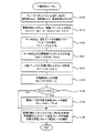
次に、こうして構成された実施例の自動車20の動作、特に、モータMG2の回生制御により車両を制動する際の動作について説明する。図2は、実施例の自動車20のメイン電子制御ユニット70により実行される制動制御ルーチンの一例を示すフローチャートである。このルーチンは、走行中のアクセルオフやブレーキオンによって制動力が要求されてから所定時間毎(例えば、8msec毎)に繰り返し実行される。
Next, the operation of the
制動制御ルーチンが実行されると、メイン電子制御ユニット70のCPU72は、まず、ブレーキペダルポジションセンサ86からのブレーキペダルポジションBPや車速センサ88からの車速V,モータMG2の回転数Nm1,Nm2,バッテリ50の残容量SOC,電池温度tbなどのデータを入力する処理を実行する(ステップS100)。ここで、回転数Nm2は、回転位置検出センサ44により検出されたモータMG2の回転子の回転位置に基づいてモータECU40により演算されたものを通信により入力するものとした。また、残容量SOCと電池温度tbは、それぞれバッテリECU52により演算されたものと温度センサ51により検出されたものを通信により入力するものとした。
When the braking control routine is executed, the
続いて、入力したブレーキペダルポジションBPと車速Vとに基づいて駆動軸としてのリングギヤ軸32aに出力すべき要求制動トルクTd*を設定すると共に要求制動パワーPd*を設定する(ステップS110)。要求制動トルクTd*は、実施例では、ブレーキペダルポジションBPと車速Vと要求制動トルクTd*との関係を予め求めて要求制動トルク設定用マップとしてROM74に記憶しておき、ブレーキペダルポジションBPと車速Vとが与えられると要求制動トルク設定用マップから対応する要求制動トルクTd*を導出することにより設定するものとした。要求制動トルク設定用マップの一例を図3に示す。また、要求制動パワーPd*は、設定した要求制動トルクTd*にリングギヤ軸32aの回転数を乗じることにより計算するものとした。なお、リングギヤ軸32aの回転数は、車速Vに換算係数Kを乗じることにより計算できる。
Subsequently, the required braking torque Td * to be output to the
こうして要求制動パワーPd*を設定すると、設定した要求制動パワーPdに基づいてモータMG2の制動パワーPm2と油圧ブレーキの制動パワーPbとを設定して(ステップS120)、設定した制動パワーPm2を入力した回転数Nm2で除してモータMG2から出力すべき目標制動トルクTm2*を設定すると共に(ステップS130)、制動パワーPbを車輪の回転数(車速Vと換算係数K2との積)で除して油圧ブレーキの制動トルクTb*を設定する(ステップS140)。制動パワーPm2の設定は、実施例では、モータMG2が分担する制動パワーPm2と油圧ブレーキが分担する制動パワーPbとの和が要求制動パワーPd*となる条件を満足しながらモータMG2の回生電力ができる限り多くなるよう設定するものとした。なお、油圧ブレーキが分担する制動パワーPbをゼロ、即ち、要求制動パワーPd*のすべてをモータMG2が分担するものとしても構わない。 When the required braking power Pd * is set in this way, the braking power Pm2 of the motor MG2 and the braking power Pb of the hydraulic brake are set based on the set required braking power Pd (step S120), and the set braking power Pm2 is input. The target braking torque Tm2 * to be output from the motor MG2 is set by dividing by the rotational speed Nm2 (step S130), and the braking power Pb is divided by the rotational speed of the wheel (product of the vehicle speed V and the conversion factor K2). A braking torque Tb * of the hydraulic brake is set (step S140). In the embodiment, the braking power Pm2 is set so that the regenerative power of the motor MG2 satisfies the condition that the sum of the braking power Pm2 shared by the motor MG2 and the braking power Pb shared by the hydraulic brake becomes the required braking power Pd *. The setting was made to increase as much as possible. Note that the braking power Pb shared by the hydraulic brake may be zero, that is, the motor MG2 may share all of the required braking power Pd *.
次に、入力した残容量SOCと電池温度tbとに基づいてバッテリ充電制限値Winを設定する(ステップS150)。バッテリ充電制限値Winは、実施例では、残容量SOCと電池温度tbとバッテリ充電制限値Winとの関係を予め実験的に求めてマップとしてROM74に記憶しておき、残容量SOCと電池温度tbとが与えられるとマップから対応するバッテリ充電制限値Winを導出することにより設定するものとした。
Next, the battery charge limit value Win is set based on the input remaining capacity SOC and battery temperature tb (step S150). In the embodiment, the battery charge limit value Win is obtained by experimentally calculating in advance the relationship among the remaining capacity SOC, the battery temperature tb, and the battery charge limit value Win, and stored in the
バッテリ充電制限値Winを設定すると、モータMG2の制動パワーPm2の絶対値がバッテリ充電制限値Winよりも大きいか否かを判定し(ステップS160)、制動パワーPm2の絶対値がバッテリ充電制限値Winよりも大きいと判定されると、制動パワーPm2からバッテリ充電制限値Winを減じて得られる値を電気ヒータ66の目標消費電力Ph*に設定する(ステップS170)。制動パワーPm2はモータMG2により回生される回生電力であるから、この回生電力がバッテリ充電制限値Winを超えるときには、超える分の電力を電気ヒータ66で消費して熱として蓄熱タンク65に蓄えることで要求制動パワーPd*をリングギヤ軸32aに出力できると共にバッテリ50への過充電や過大な電力による充電を防止しながら回生エネルギを無駄なく蓄えることができるのである。この蓄熱タンク65に蓄えられる熱の利用については後述する。
When the battery charge limit value Win is set, it is determined whether or not the absolute value of the braking power Pm2 of the motor MG2 is larger than the battery charge limit value Win (step S160), and the absolute value of the braking power Pm2 is determined as the battery charge limit value Win. Is determined to be larger than the braking power Pm2, the value obtained by subtracting the battery charging limit value Win is set as the target power consumption Ph * of the electric heater 66 (step S170). Since the braking power Pm2 is regenerative power regenerated by the motor MG2, when the regenerative power exceeds the battery charge limit value Win, the excess power is consumed by the electric heater 66 and stored as heat in the
こうして目標制動トルクTm2*と目標消費電力Ph*とが設定されると、目標制動トルクTm2*をモータECU40に送信し、制動トルクTb*で油圧ブレーキを制御すると共に目標消費電力Ph*で電流調節回路67を制御して(ステップS170)、本ルーチンを終了する。これにより、目標トルクTm2*を受け取ったモータECU40は、目標トルクTm2*に見合うトルクでモータMG2が運転されるようインバータ42のスイッチング素子をスイッチング制御する。また、油圧ブレーキの制御は、具体的には、制動トルクTb*に見合うトルクが車輪に作用するよう油圧ブレーキに作用する油圧を調節することにより行ない、電流調節回路67の制御は、目標消費電力Ph*に見合う電流が電気ヒータ66に印加されるよう電流調節回路67のスイッチング素子を制御することにより行なう。
When the target braking torque Tm2 * and the target power consumption Ph * are thus set, the target braking torque Tm2 * is transmitted to the
次に、こうして蓄熱タンク65に蓄積された熱を用いてエンジン22を暖機する際の動作について説明する。図4は、エンジン始動時制御ルーチンの一例を示すフローチャートである。このルーチンは、エンジン22の始動条件が成立(例えば、イグニッションスイッチ80がオン)してエンジン22が始動してから所定時間毎(例えば、8msec毎)に繰り返し実行される。
Next, the operation when the
エンジン始動時制御ルーチンが実行されると、温度センサ69により検出されエンジンECU24による通信により入力されたエンジン水温teを読み込み(ステップS200)、読み込んだエンジン水温teがエンジン22の暖機を必要とする低い温度として設定されている閾値tref未満か否かを判定する(ステップS210)。エンジン水温teが閾値tref未満と判定されると、加温用通路62と循環形成管路63とが接続されるよう三方弁68を駆動制御して(ステップS220)、本ルーチンを終了する。これにより、加温用循環路が形成され蓄熱タンク65に蓄積された熱交換媒体がエンジン22に供給されてエンジン22の暖機が促進される。一方、エンジン水温teが閾値tref未満でないと判定されると、冷却用通路61と循環形成管路63とが接続されるよう三方弁68を駆動制御して(ステップS230)、本ルーチンを終了する。これにより、冷却用循環路が形成され外気との熱交換により冷却された熱交換媒体がエンジン22に供給されてエンジン22が冷却される。
When the engine start time control routine is executed, the engine water temperature te detected by the temperature sensor 69 and input by communication by the
以上説明した実施例の自動車20によれば、モータMG2の制動パワーPm2の絶対値がバッテリ充電制限値Winよりも大きいときには、制動パワーPm2(回生電力)とバッテリ充電制限値Winとの偏差の電力を電気ヒータ66により消費して熱エネルギとして蓄熱タンク65に蓄積させるから、要求制動パワーPd*をリングギヤ軸32aに出力しながらモータMG2の回生電力に基づくエネルギを無駄なく蓄えることができると共に必要に応じて熱として利用することが可能となる。この結果、車両全体のエネルギ効率をより向上させることができる。しかも、蓄積した熱エネルギをエンジン22の暖機が必要なときに利用するから、エンジン22を効率よく暖機することができる。
According to the
実施例の自動車20では、電気ヒータ66で加熱した熱交換媒体を蓄熱タンク65に蓄えるものとしたが、これに加えてエンジン22が運転状態にあるときにエンジン22により加温された熱交換媒体を回収して蓄熱タンク65に蓄えるものとしてもよい。この場合、例えば、蓄熱タンク65内に蓄えられている熱交換媒体の温度を検出し、検出した温度が低温の状態にあるときに三方弁68により加温用通路62と循環形成管路63とを接続してポンプの駆動によりエンジン22で温められた熱交換媒体を蓄熱タンク65に供給するものとするものとすればよい。また、実施例の自動車20では、蓄熱タンク65に電気ヒータ66を内蔵するものとして構成したが、図5に示すように、蓄熱タンク165と電気ヒータ166とを別々に配置するものとしてもよい。この例では、三方弁168a,168bにより熱交換器164とエンジン22とを接続する冷却用循環路を形成すると共にエンジン22のクランクシャフト26に連結された図示しないポンプの駆動により熱交換器164で冷却した熱交換媒体をエンジン22に供給してエンジン22を冷却できると同時に、三方弁168c,168dにより冷却用循環路とは独立に蓄熱タンク165と電気ヒータ166とを接続する蓄熱用循環路を形成すると共にポンプ190の駆動により電気ヒータ166で加熱した熱交換媒体を蓄熱タンク165に供給して熱エネルギとして蓄えることができる。そして、エンジン22を始動する際には三方弁168a〜168dにより熱交換器164や電気ヒータ166をバイパスして蓄熱タンク165とエンジン22とを接続する加温用循環路を形成すると共に蓄熱タンク165内の加熱された熱交換媒体をエンジン22に供給してエンジン22を暖機することができる。また、この加温用循環路を形成して暖機後のエンジン22により加温された熱交換媒体を蓄熱タンク165に供給して熱エネルギとして回収することもできる。
In the
実施例の自動車20では、蓄熱タンク65に蓄積された熱をエンジン22の暖機に用いるものとしたが、乗員室内の暖房する暖房装置に用いるものとしてもよい。この場合、蓄熱タンクの加熱された熱交換媒体を乗員室内に設置された熱交換器に供給して乗員室内の空気や外気と熱交換させればよい。また、駆動輪39a,39bに動力を入出力可能な電動機に電力を供給する燃料電池を備える自動車に適用する場合には、蓄熱タンク65に蓄積された熱を燃料電池の暖機に用いるものとしてもよい。
In the
実施例の自動車20では、電気ヒータ66により熱交換媒体を加熱するものとしたが、熱交換媒体を加熱できれば、如何なる発熱器、例えば、モータMG1を用いるものとしてもよい。
In the
実施例の自動車20では、エンジン22の動力を動力分配統合機構30を介して駆動輪39a,39bに接続された駆動軸としてのリングギヤ軸32aに出力するものとしたが、車軸に接続された発電可能な電動機を備える自動車であれば、如何なる自動車に適用するものとしてもよい。例えば、車軸に接続されたモータを備える通常の電気自動車に適用したり、図6の変形例の自動車120に例示するように、エンジン22のクランクシャフト26に接続されたインナーロータ132と駆動輪39a,39bに動力を出力する駆動軸に接続されたアウターロータ134とを有しエンジン22の動力の一部を駆動軸に伝達すると共に残余の動力を電力に変換する対ロータ電動機130と駆動軸に接続された発電可能なモータ140とを備える自動車に適用するものとしてもよい。
In the
以上、本発明の実施の形態について実施例を用いて説明したが、本発明はこうした実施例に何等限定されるものではなく、本発明の要旨を逸脱しない範囲内において、種々なる形態で実施し得ることは勿論である。 The embodiments of the present invention have been described using the embodiments. However, the present invention is not limited to these embodiments, and can be implemented in various forms without departing from the gist of the present invention. Of course you get.
20,120 ハイブリッド自動車、22 エンジン、24 エンジン用電子制御ユニット(エンジンECU)、26 クランクシャフト、28 ダンパ、30 動力分配統合機構、31 サンギヤ、32 リングギヤ、32a リングギヤ軸、33 ピニオンギヤ、34 キャリア、37 ギヤ機構、38 デファレンシャルギヤ、39a,39b 駆動輪、40 モータ用電子制御ユニット(モータECU)、41,42 インバータ、43,44 回転位置検出センサ、50 バッテリ、51 温度センサ、52 バッテリ用電子制御ユニット(バッテリECU)、54 電力ライン、60,160 温度管理装置、61 冷却用通路、62 加温用通路、63 循環形成管路、64、164 熱交換器、65,165 蓄熱タンク、66,166 電気ヒータ、67 電流調節回路、68、168a〜168d 三方弁、69 温度センサ、70 ハイブリッド用電子制御ユニット、72 CPU、74 ROM、76 RAM、80 イグニッションスイッチ、81 シフトレバー、82 シフトポジションセンサ、83 アクセルペダル、84 アクセルペダルポジションセンサ、85 ブレーキペダル、86 ブレーキペダルポジションセンサ、88 車速センサ、130 対ロータ電動機、132 インナーロータ、 134 アウターロータ、140 モータ、MG1,MG2 モータ、190 ポンプ。
20, 120 Hybrid vehicles, 22 engines, 24 engine electronic control units (engine ECUs), 26 crankshafts, 28 dampers, 30 power distribution integration mechanisms, 31 sun gears, 32 ring gears, 32a ring gear shafts, 33 pinion gears, 34 carriers, 37 Gear mechanism, 38 differential gear, 39a, 39b drive wheel, 40 motor electronic control unit (motor ECU), 41, 42 inverter, 43, 44 rotational position detection sensor, 50 battery, 51 temperature sensor, 52 battery electronic control unit (Battery ECU), 54 power line, 60,160 temperature management device, 61 cooling passage, 62 heating passage, 63 circulation formation pipe, 64, 164 heat exchanger, 65,165 heat storage tank, 66,166 electricity Heater, 67 Current adjustment Circuit, 68, 168a to 168d Three-way valve, 69 Temperature sensor, 70 Hybrid electronic control unit, 72 CPU, 74 ROM, 76 RAM, 80 Ignition switch, 81 Shift lever, 82 Shift position sensor, 83 Accelerator pedal, 84 Accelerator pedal Position sensor, 85 brake pedal, 86 brake pedal position sensor, 88 vehicle speed sensor, 130 rotor motor, 132 inner rotor, 134 outer rotor, 140 motor, MG1, MG2 motor, 190 pump.
Claims (10)
前記回生手段による回生電力を蓄電可能な蓄電手段と、
電力を熱に変換すると共に変換した熱を蓄積可能な蓄熱手段と、
前記回生手段により回生される回生電力が前記蓄電手段の蓄電可能最大電力を超えるとき、前記電動機により回生される回生電力の少なくとも一部が熱に変換されて蓄積されるよう前記蓄熱手段を制御する制御手段と、
を備える自動車。 An automobile equipped with a regenerative means capable of regenerating kinetic energy of a vehicle,
Power storage means capable of storing regenerative power by the regenerative means;
Heat storage means capable of converting electric power into heat and storing the converted heat;
When the regenerative power regenerated by the regenerative means exceeds the maximum power that can be stored in the power storage means, the heat storage means is controlled so that at least a part of the regenerative power regenerated by the electric motor is converted into heat and accumulated. Control means;
Automobile equipped with.
熱を利用する熱利用機器と、
前記蓄熱手段に蓄積された熱を前記熱利用機器に供給する熱供給手段と、を備え、
前記制御手段は、前記熱利用機器による熱の利用が要請されたときに前記蓄熱手段に蓄積された熱が前記熱利用機器に供給されるよう前記熱供給手段を制御する手段である
自動車。 The automobile according to claim 1,
Heat-using equipment that uses heat;
Heat supply means for supplying heat accumulated in the heat storage means to the heat utilization device,
The control means is a means for controlling the heat supply means so that the heat accumulated in the heat storage means is supplied to the heat utilization equipment when use of heat by the heat utilization equipment is requested.
前記熱利用機器は、内燃機関であり、
前記制御手段は、前記内燃機関の暖機が要請されたときに前記蓄熱手段に蓄積された熱が該内燃機関に供給されるよう前記熱供給手段を制御する手段である
自動車。 The automobile according to claim 2,
The heat utilization device is an internal combustion engine,
The vehicle is a vehicle that controls the heat supply means so that the heat stored in the heat storage means is supplied to the internal combustion engine when a warm-up of the internal combustion engine is requested.
前記内燃機関の温度を検出する温度検出手段を備え、
前記制御手段は、前記内燃機関の始動後前記検出される内燃機関の温度が所定温度以上となるまで前記蓄熱手段に蓄積された熱が該内燃機関に供給されるよう前記熱供給手段を制御する手段である
自動車。 The automobile according to claim 3,
Temperature detecting means for detecting the temperature of the internal combustion engine,
The control means controls the heat supply means so that the heat stored in the heat storage means is supplied to the internal combustion engine until the detected temperature of the internal combustion engine becomes equal to or higher than a predetermined temperature after the internal combustion engine is started. The vehicle that is the means.
前記熱利用機器は、燃料電池であり、
前記制御手段は、前記燃料電池の暖機が要請されたときに前記蓄熱手段に蓄積された熱が該燃料電池に供給されるよう前記熱供給手段を制御する手段である
自動車。 The automobile according to claim 2,
The heat utilization device is a fuel cell,
The control means is means for controlling the heat supply means so that the heat stored in the heat storage means is supplied to the fuel cell when a warm-up of the fuel cell is requested.
前記熱利用機器は、乗員室内を暖房する暖房装置であり、
前記制御手段は、前記暖房装置の作動が要請されたときに前記蓄熱手段に蓄積された熱が該暖房装置に供給されるよう前記熱供給手段を制御する手段である
自動車。 The automobile according to claim 2,
The heat utilization device is a heating device that heats the passenger compartment,
The control means is a means for controlling the heat supply means so that the heat stored in the heat storage means is supplied to the heating device when an operation of the heating device is requested.
前記蓄電手段の状態を検出する状態検出手段を備え、
前記制御手段は、車両を制動させる制動力の付与が要求されたとき、該要求された制動力が作用するよう前記回生手段を回生制御すると共に該回生制御によって前記回生手段により回生される回生電力と前記状態検出手段により検出された蓄電手段の状態に基づいて設定される前記蓄電手段の蓄電可能最大電力との偏差の電力が前記蓄熱手段で消費されるよう該蓄熱手段を制御する手段である
自動車。 The automobile according to any one of claims 1 to 6,
Comprising a state detecting means for detecting the state of the power storage means,
The control means regeneratively controls the regenerative means so that the requested braking force acts when regenerative power is regenerated by the regenerative means when a braking force is applied to brake the vehicle. And a means for controlling the heat storage means so that a power difference between the power storage means and the maximum chargeable power of the power storage means set based on the state of the power storage means detected by the state detection means is consumed by the heat storage means. Automobile.
内燃機関と、
該内燃機関からの動力の一部を電力に変換すると共に残余を前記車軸に接続された駆動軸に伝達する電力変換動力伝達手段と、を備え、
前記電動機は、前記駆動軸に動力を入出力可能な電動機である
自動車。
The automobile according to claim 9,
An internal combustion engine;
Power conversion power transmission means for converting a part of the power from the internal combustion engine into electric power and transmitting the remainder to a drive shaft connected to the axle,
The motor is an electric motor capable of inputting and outputting power to the drive shaft.
Priority Applications (1)
| Application Number | Priority Date | Filing Date | Title |
|---|---|---|---|
| JP2003364300A JP2005130629A (en) | 2003-10-24 | 2003-10-24 | Automobile |
Applications Claiming Priority (1)
| Application Number | Priority Date | Filing Date | Title |
|---|---|---|---|
| JP2003364300A JP2005130629A (en) | 2003-10-24 | 2003-10-24 | Automobile |
Publications (1)
| Publication Number | Publication Date |
|---|---|
| JP2005130629A true JP2005130629A (en) | 2005-05-19 |
Family
ID=34643322
Family Applications (1)
| Application Number | Title | Priority Date | Filing Date |
|---|---|---|---|
| JP2003364300A Pending JP2005130629A (en) | 2003-10-24 | 2003-10-24 | Automobile |
Country Status (1)
| Country | Link |
|---|---|
| JP (1) | JP2005130629A (en) |
Cited By (26)
| Publication number | Priority date | Publication date | Assignee | Title |
|---|---|---|---|---|
| JP2008182855A (en) * | 2007-01-25 | 2008-08-07 | Toyota Motor Corp | Vehicle and control method thereof |
| WO2008136278A1 (en) * | 2007-04-27 | 2008-11-13 | Toyota Jidosha Kabushiki Kaisha | O3 producing device, and exhaust cleaning system for internal combustion engine |
| JP2010167977A (en) * | 2009-01-26 | 2010-08-05 | Toyota Central R&D Labs Inc | Secondary battery system and vehicle equipped with the same |
| JP2012530642A (en) * | 2009-06-25 | 2012-12-06 | リ−テック・バッテリー・ゲーエムベーハー | Vehicle having drive device |
| WO2012169009A1 (en) * | 2011-06-07 | 2012-12-13 | トヨタ自動車株式会社 | Electric vehicle and method for controlling electric vehicle |
| JP2013139226A (en) * | 2012-01-05 | 2013-07-18 | Toyota Motor Corp | Control apparatus of hybrid vehicle |
| JP2013163494A (en) * | 2012-02-13 | 2013-08-22 | Denso Corp | Control device of hybrid vehicle |
| JP2013163495A (en) * | 2012-02-13 | 2013-08-22 | Denso Corp | Control device of hybrid vehicle |
| US9187083B2 (en) | 2009-09-16 | 2015-11-17 | Polaris Industries Inc. | System and method for charging an on-board battery of an electric vehicle |
| WO2016017083A1 (en) * | 2014-07-29 | 2016-02-04 | 株式会社デンソー | Energy management system |
| JP2016153277A (en) * | 2015-02-20 | 2016-08-25 | 三菱自動車工業株式会社 | Vehicle controller |
| JP2016153276A (en) * | 2015-02-20 | 2016-08-25 | 三菱自動車工業株式会社 | Vehicle controller |
| US9802605B2 (en) | 2009-09-16 | 2017-10-31 | Swissauto Powersport Llc | Electric vehicle and on-board battery charging apparatus therefor |
| US10300786B2 (en) | 2014-12-19 | 2019-05-28 | Polaris Industries Inc. | Utility vehicle |
| CN111483306A (en) * | 2019-01-28 | 2020-08-04 | 本田技研工业株式会社 | Heat distribution device for hybrid vehicle |
| US10744868B2 (en) | 2016-06-14 | 2020-08-18 | Polaris Industries Inc. | Hybrid utility vehicle |
| US10780770B2 (en) | 2018-10-05 | 2020-09-22 | Polaris Industries Inc. | Hybrid utility vehicle |
| US11370266B2 (en) | 2019-05-16 | 2022-06-28 | Polaris Industries Inc. | Hybrid utility vehicle |
| CN114834252A (en) * | 2021-02-02 | 2022-08-02 | 奥迪股份公司 | Method for operating at least one electromechanical actuator of a motor vehicle and motor vehicle |
| US12172518B2 (en) | 2019-04-30 | 2024-12-24 | Polaris Industries Inc. | Vehicle |
| US12187127B2 (en) | 2020-05-15 | 2025-01-07 | Polaris Industries Inc. | Off-road vehicle |
| US12214654B2 (en) | 2021-05-05 | 2025-02-04 | Polaris Industries Inc. | Exhaust assembly for a utility vehicle |
| US12385429B2 (en) | 2022-06-13 | 2025-08-12 | Polaris Industries Inc. | Powertrain for a utility vehicle |
| US12384464B2 (en) | 2020-05-15 | 2025-08-12 | Polaris Industries Inc. | Off-road vehicle |
| US12485981B2 (en) | 2021-03-24 | 2025-12-02 | Polaris Industries Inc. | Electric recreational vehicle |
| US12552246B2 (en) | 2015-05-15 | 2026-02-17 | Polaris Industries Inc. | Utility vehicle |
Citations (5)
| Publication number | Priority date | Publication date | Assignee | Title |
|---|---|---|---|---|
| JP2000059918A (en) * | 1998-08-12 | 2000-02-25 | Hitachi Ltd | Automobile |
| JP2001054202A (en) * | 1999-08-05 | 2001-02-23 | Nissan Motor Co Ltd | Vehicle braking force control device |
| JP2001065384A (en) * | 1999-08-24 | 2001-03-13 | Toyota Motor Corp | Warm-up promotion device for internal combustion engine |
| JP2003184721A (en) * | 2001-12-13 | 2003-07-03 | Toyota Motor Corp | Heat storage device for hybrid system |
| JP2003293770A (en) * | 2002-04-03 | 2003-10-15 | Toyota Motor Corp | Hot water storage system for vehicles |
-
2003
- 2003-10-24 JP JP2003364300A patent/JP2005130629A/en active Pending
Patent Citations (5)
| Publication number | Priority date | Publication date | Assignee | Title |
|---|---|---|---|---|
| JP2000059918A (en) * | 1998-08-12 | 2000-02-25 | Hitachi Ltd | Automobile |
| JP2001054202A (en) * | 1999-08-05 | 2001-02-23 | Nissan Motor Co Ltd | Vehicle braking force control device |
| JP2001065384A (en) * | 1999-08-24 | 2001-03-13 | Toyota Motor Corp | Warm-up promotion device for internal combustion engine |
| JP2003184721A (en) * | 2001-12-13 | 2003-07-03 | Toyota Motor Corp | Heat storage device for hybrid system |
| JP2003293770A (en) * | 2002-04-03 | 2003-10-15 | Toyota Motor Corp | Hot water storage system for vehicles |
Cited By (47)
| Publication number | Priority date | Publication date | Assignee | Title |
|---|---|---|---|---|
| JP2008182855A (en) * | 2007-01-25 | 2008-08-07 | Toyota Motor Corp | Vehicle and control method thereof |
| WO2008136278A1 (en) * | 2007-04-27 | 2008-11-13 | Toyota Jidosha Kabushiki Kaisha | O3 producing device, and exhaust cleaning system for internal combustion engine |
| US20100064669A1 (en) * | 2007-04-27 | 2010-03-18 | Toyota Jidosha Kabushiki Kaisha | O3 production apparatus and exhaust gas purification system for internal combustion engine |
| CN101668930B (en) * | 2007-04-27 | 2012-07-18 | 丰田自动车株式会社 | O3 generation device and exhaust purification system of internal combustion engine |
| US8266895B2 (en) | 2007-04-27 | 2012-09-18 | Toyota Jidosha Kabushiki Kaisha | O3 production apparatus and exhaust gas purification system for internal combustion engine |
| JP2010167977A (en) * | 2009-01-26 | 2010-08-05 | Toyota Central R&D Labs Inc | Secondary battery system and vehicle equipped with the same |
| US8935023B2 (en) | 2009-01-26 | 2015-01-13 | Kabushiki Kaisha Toyota Chuo Kenkyusho | Secondary battery system and vehicle having secondary battery system |
| JP2012530642A (en) * | 2009-06-25 | 2012-12-06 | リ−テック・バッテリー・ゲーエムベーハー | Vehicle having drive device |
| US9802605B2 (en) | 2009-09-16 | 2017-10-31 | Swissauto Powersport Llc | Electric vehicle and on-board battery charging apparatus therefor |
| US9187083B2 (en) | 2009-09-16 | 2015-11-17 | Polaris Industries Inc. | System and method for charging an on-board battery of an electric vehicle |
| CN103596798A (en) * | 2011-06-07 | 2014-02-19 | 丰田自动车株式会社 | Electric vehicle and control method for electric vehicle |
| WO2012169009A1 (en) * | 2011-06-07 | 2012-12-13 | トヨタ自動車株式会社 | Electric vehicle and method for controlling electric vehicle |
| JPWO2012169009A1 (en) * | 2011-06-07 | 2015-02-23 | トヨタ自動車株式会社 | Electric vehicle and control method of electric vehicle |
| CN103596798B (en) * | 2011-06-07 | 2015-11-25 | 丰田自动车株式会社 | Electric vehicle and control method for electric vehicle |
| US9233613B2 (en) | 2011-06-07 | 2016-01-12 | Toyota Jidosha Kabushiki Kaisha | Electrically powered vehicle and method for controlling electrically powered vehicle |
| JP2013139226A (en) * | 2012-01-05 | 2013-07-18 | Toyota Motor Corp | Control apparatus of hybrid vehicle |
| JP2013163494A (en) * | 2012-02-13 | 2013-08-22 | Denso Corp | Control device of hybrid vehicle |
| JP2013163495A (en) * | 2012-02-13 | 2013-08-22 | Denso Corp | Control device of hybrid vehicle |
| CN106470882A (en) * | 2014-07-29 | 2017-03-01 | 株式会社电装 | energy management system |
| JP2016032348A (en) * | 2014-07-29 | 2016-03-07 | 株式会社デンソー | Energy management system |
| CN106470882B (en) * | 2014-07-29 | 2019-01-18 | 株式会社电装 | Energy management system |
| US10279657B2 (en) | 2014-07-29 | 2019-05-07 | Denso Corporation | Energy management system |
| WO2016017083A1 (en) * | 2014-07-29 | 2016-02-04 | 株式会社デンソー | Energy management system |
| US11884148B2 (en) | 2014-12-19 | 2024-01-30 | Polaris Industries Inc. | Utility vehicle |
| US10300786B2 (en) | 2014-12-19 | 2019-05-28 | Polaris Industries Inc. | Utility vehicle |
| US12122228B2 (en) | 2014-12-19 | 2024-10-22 | Polaris Industries Inc. | Utility vehicle |
| US10800250B2 (en) | 2014-12-19 | 2020-10-13 | Polaris Industries Inc. | Utility vehicle |
| JP2016153277A (en) * | 2015-02-20 | 2016-08-25 | 三菱自動車工業株式会社 | Vehicle controller |
| JP2016153276A (en) * | 2015-02-20 | 2016-08-25 | 三菱自動車工業株式会社 | Vehicle controller |
| US12552246B2 (en) | 2015-05-15 | 2026-02-17 | Polaris Industries Inc. | Utility vehicle |
| US10744868B2 (en) | 2016-06-14 | 2020-08-18 | Polaris Industries Inc. | Hybrid utility vehicle |
| US10780770B2 (en) | 2018-10-05 | 2020-09-22 | Polaris Industries Inc. | Hybrid utility vehicle |
| US12420624B2 (en) | 2018-10-05 | 2025-09-23 | Polaris Industries, Inc. | Hybrid utility vehicle |
| JP7111635B2 (en) | 2019-01-28 | 2022-08-02 | 本田技研工業株式会社 | Heat distribution device for hybrid vehicle |
| CN111483306A (en) * | 2019-01-28 | 2020-08-04 | 本田技研工业株式会社 | Heat distribution device for hybrid vehicle |
| JP2020117167A (en) * | 2019-01-28 | 2020-08-06 | 本田技研工業株式会社 | Heat distribution device of hybrid vehicle |
| US12172518B2 (en) | 2019-04-30 | 2024-12-24 | Polaris Industries Inc. | Vehicle |
| US12194808B2 (en) | 2019-05-16 | 2025-01-14 | Polaris Industries Inc. | Hybrid utility vehicle |
| US12311728B2 (en) | 2019-05-16 | 2025-05-27 | Polaris Industries Inc. | Hybrid utility vehicle |
| US11370266B2 (en) | 2019-05-16 | 2022-06-28 | Polaris Industries Inc. | Hybrid utility vehicle |
| US12337690B2 (en) | 2020-05-15 | 2025-06-24 | Polaris Industries Inc. | Off-road vehicle |
| US12384464B2 (en) | 2020-05-15 | 2025-08-12 | Polaris Industries Inc. | Off-road vehicle |
| US12187127B2 (en) | 2020-05-15 | 2025-01-07 | Polaris Industries Inc. | Off-road vehicle |
| CN114834252A (en) * | 2021-02-02 | 2022-08-02 | 奥迪股份公司 | Method for operating at least one electromechanical actuator of a motor vehicle and motor vehicle |
| US12485981B2 (en) | 2021-03-24 | 2025-12-02 | Polaris Industries Inc. | Electric recreational vehicle |
| US12214654B2 (en) | 2021-05-05 | 2025-02-04 | Polaris Industries Inc. | Exhaust assembly for a utility vehicle |
| US12385429B2 (en) | 2022-06-13 | 2025-08-12 | Polaris Industries Inc. | Powertrain for a utility vehicle |
Similar Documents
| Publication | Publication Date | Title |
|---|---|---|
| JP2005130629A (en) | Automobile | |
| KR100789359B1 (en) | Hybrid vehicle and its control method | |
| CN101065565B (en) | Motor vehicle and control method of motor vehicle | |
| JP4172524B1 (en) | Vehicle and control method thereof | |
| JP3809824B2 (en) | Hybrid car | |
| CN101663187B (en) | Vehicle and control method thereof | |
| US9127582B2 (en) | Control apparatus for hybrid vehicle | |
| JP2000092614A (en) | Hybrid vehicle charge / discharge state control device | |
| JP5282708B2 (en) | Hybrid vehicle and control method thereof | |
| JP2006037780A (en) | Power output apparatus and control method thereof | |
| JP4229105B2 (en) | Hybrid vehicle and control method thereof | |
| JP4534586B2 (en) | Power output apparatus, automobile equipped with the same, and control method of power output apparatus | |
| JP2009202771A (en) | Vehicle and control method thereof, and drive unit and control method thereof | |
| JP3894160B2 (en) | Hybrid vehicle and control method thereof | |
| JP2007116773A (en) | DRIVE DEVICE, VEHICLE MOUNTING THE SAME, AND DRIVE DEVICE CONTROL METHOD | |
| JP2011098636A (en) | Hybrid vehicle and control method thereof | |
| JP4784300B2 (en) | Automobile and control method thereof | |
| JP2008163867A (en) | Vehicle control device | |
| JP2007326478A (en) | Vehicle and control method thereof | |
| JP2005201177A (en) | Drive device and hybrid vehicle equipped with the same | |
| JP2007290614A (en) | Vehicle and control method thereof | |
| JP2006336510A (en) | Automobile and control method thereof | |
| JP2016152754A (en) | Automobile | |
| JP2007145051A (en) | Vehicle and control method thereof |
Legal Events
| Date | Code | Title | Description |
|---|---|---|---|
| A621 | Written request for application examination |
Free format text: JAPANESE INTERMEDIATE CODE: A621 Effective date: 20060522 |
|
| A131 | Notification of reasons for refusal |
Free format text: JAPANESE INTERMEDIATE CODE: A131 Effective date: 20070227 |
|
| A02 | Decision of refusal |
Free format text: JAPANESE INTERMEDIATE CODE: A02 Effective date: 20070626 |