EP4284690B1 - Obstacle avoidance method - Google Patents
Obstacle avoidance method Download PDFInfo
- Publication number
- EP4284690B1 EP4284690B1 EP22700841.4A EP22700841A EP4284690B1 EP 4284690 B1 EP4284690 B1 EP 4284690B1 EP 22700841 A EP22700841 A EP 22700841A EP 4284690 B1 EP4284690 B1 EP 4284690B1
- Authority
- EP
- European Patent Office
- Prior art keywords
- ref
- motor vehicle
- steering
- ffwd
- vehicle
- Prior art date
- Legal status (The legal status is an assumption and is not a legal conclusion. Google has not performed a legal analysis and makes no representation as to the accuracy of the status listed.)
- Active
Links
Images


Classifications
-
- B—PERFORMING OPERATIONS; TRANSPORTING
- B62—LAND VEHICLES FOR TRAVELLING OTHERWISE THAN ON RAILS
- B62D—MOTOR VEHICLES; TRAILERS
- B62D6/00—Arrangements for automatically controlling steering depending on driving conditions sensed and responded to, e.g. control circuits
- B62D6/001—Arrangements for automatically controlling steering depending on driving conditions sensed and responded to, e.g. control circuits the torque NOT being among the input parameters
-
- B—PERFORMING OPERATIONS; TRANSPORTING
- B60—VEHICLES IN GENERAL
- B60W—CONJOINT CONTROL OF VEHICLE SUB-UNITS OF DIFFERENT TYPE OR DIFFERENT FUNCTION; CONTROL SYSTEMS SPECIALLY ADAPTED FOR HYBRID VEHICLES; ROAD VEHICLE DRIVE CONTROL SYSTEMS FOR PURPOSES NOT RELATED TO THE CONTROL OF A PARTICULAR SUB-UNIT
- B60W30/00—Purposes of road vehicle drive control systems not related to the control of a particular sub-unit, e.g. of systems using conjoint control of vehicle sub-units
- B60W30/08—Active safety systems predicting or avoiding probable or impending collision or attempting to minimise its consequences
- B60W30/09—Taking automatic action to avoid collision, e.g. braking and steering
-
- B—PERFORMING OPERATIONS; TRANSPORTING
- B60—VEHICLES IN GENERAL
- B60W—CONJOINT CONTROL OF VEHICLE SUB-UNITS OF DIFFERENT TYPE OR DIFFERENT FUNCTION; CONTROL SYSTEMS SPECIALLY ADAPTED FOR HYBRID VEHICLES; ROAD VEHICLE DRIVE CONTROL SYSTEMS FOR PURPOSES NOT RELATED TO THE CONTROL OF A PARTICULAR SUB-UNIT
- B60W10/00—Conjoint control of vehicle sub-units of different type or different function
- B60W10/20—Conjoint control of vehicle sub-units of different type or different function including control of steering systems
-
- B—PERFORMING OPERATIONS; TRANSPORTING
- B60—VEHICLES IN GENERAL
- B60W—CONJOINT CONTROL OF VEHICLE SUB-UNITS OF DIFFERENT TYPE OR DIFFERENT FUNCTION; CONTROL SYSTEMS SPECIALLY ADAPTED FOR HYBRID VEHICLES; ROAD VEHICLE DRIVE CONTROL SYSTEMS FOR PURPOSES NOT RELATED TO THE CONTROL OF A PARTICULAR SUB-UNIT
- B60W40/00—Estimation or calculation of non-directly measurable driving parameters for road vehicle drive control systems not related to the control of a particular sub unit, e.g. by using mathematical models
- B60W40/02—Estimation or calculation of non-directly measurable driving parameters for road vehicle drive control systems not related to the control of a particular sub unit, e.g. by using mathematical models related to ambient conditions
-
- B—PERFORMING OPERATIONS; TRANSPORTING
- B60—VEHICLES IN GENERAL
- B60W—CONJOINT CONTROL OF VEHICLE SUB-UNITS OF DIFFERENT TYPE OR DIFFERENT FUNCTION; CONTROL SYSTEMS SPECIALLY ADAPTED FOR HYBRID VEHICLES; ROAD VEHICLE DRIVE CONTROL SYSTEMS FOR PURPOSES NOT RELATED TO THE CONTROL OF A PARTICULAR SUB-UNIT
- B60W40/00—Estimation or calculation of non-directly measurable driving parameters for road vehicle drive control systems not related to the control of a particular sub unit, e.g. by using mathematical models
- B60W40/10—Estimation or calculation of non-directly measurable driving parameters for road vehicle drive control systems not related to the control of a particular sub unit, e.g. by using mathematical models related to vehicle motion
- B60W40/109—Lateral acceleration
-
- B—PERFORMING OPERATIONS; TRANSPORTING
- B60—VEHICLES IN GENERAL
- B60W—CONJOINT CONTROL OF VEHICLE SUB-UNITS OF DIFFERENT TYPE OR DIFFERENT FUNCTION; CONTROL SYSTEMS SPECIALLY ADAPTED FOR HYBRID VEHICLES; ROAD VEHICLE DRIVE CONTROL SYSTEMS FOR PURPOSES NOT RELATED TO THE CONTROL OF A PARTICULAR SUB-UNIT
- B60W40/00—Estimation or calculation of non-directly measurable driving parameters for road vehicle drive control systems not related to the control of a particular sub unit, e.g. by using mathematical models
- B60W40/10—Estimation or calculation of non-directly measurable driving parameters for road vehicle drive control systems not related to the control of a particular sub unit, e.g. by using mathematical models related to vehicle motion
- B60W40/112—Roll movement
-
- B—PERFORMING OPERATIONS; TRANSPORTING
- B60—VEHICLES IN GENERAL
- B60W—CONJOINT CONTROL OF VEHICLE SUB-UNITS OF DIFFERENT TYPE OR DIFFERENT FUNCTION; CONTROL SYSTEMS SPECIALLY ADAPTED FOR HYBRID VEHICLES; ROAD VEHICLE DRIVE CONTROL SYSTEMS FOR PURPOSES NOT RELATED TO THE CONTROL OF A PARTICULAR SUB-UNIT
- B60W50/00—Details of control systems for road vehicle drive control not related to the control of a particular sub-unit, e.g. process diagnostic or vehicle driver interfaces
- B60W2050/0001—Details of the control system
- B60W2050/0002—Automatic control, details of type of controller or control system architecture
- B60W2050/0008—Feedback, closed loop systems or details of feedback error signal
-
- B—PERFORMING OPERATIONS; TRANSPORTING
- B60—VEHICLES IN GENERAL
- B60W—CONJOINT CONTROL OF VEHICLE SUB-UNITS OF DIFFERENT TYPE OR DIFFERENT FUNCTION; CONTROL SYSTEMS SPECIALLY ADAPTED FOR HYBRID VEHICLES; ROAD VEHICLE DRIVE CONTROL SYSTEMS FOR PURPOSES NOT RELATED TO THE CONTROL OF A PARTICULAR SUB-UNIT
- B60W50/00—Details of control systems for road vehicle drive control not related to the control of a particular sub-unit, e.g. process diagnostic or vehicle driver interfaces
- B60W2050/0001—Details of the control system
- B60W2050/0002—Automatic control, details of type of controller or control system architecture
- B60W2050/0012—Feedforward or open loop systems
-
- B—PERFORMING OPERATIONS; TRANSPORTING
- B60—VEHICLES IN GENERAL
- B60W—CONJOINT CONTROL OF VEHICLE SUB-UNITS OF DIFFERENT TYPE OR DIFFERENT FUNCTION; CONTROL SYSTEMS SPECIALLY ADAPTED FOR HYBRID VEHICLES; ROAD VEHICLE DRIVE CONTROL SYSTEMS FOR PURPOSES NOT RELATED TO THE CONTROL OF A PARTICULAR SUB-UNIT
- B60W50/00—Details of control systems for road vehicle drive control not related to the control of a particular sub-unit, e.g. process diagnostic or vehicle driver interfaces
- B60W2050/0001—Details of the control system
- B60W2050/0043—Signal treatments, identification of variables or parameters, parameter estimation or state estimation
-
- B—PERFORMING OPERATIONS; TRANSPORTING
- B60—VEHICLES IN GENERAL
- B60W—CONJOINT CONTROL OF VEHICLE SUB-UNITS OF DIFFERENT TYPE OR DIFFERENT FUNCTION; CONTROL SYSTEMS SPECIALLY ADAPTED FOR HYBRID VEHICLES; ROAD VEHICLE DRIVE CONTROL SYSTEMS FOR PURPOSES NOT RELATED TO THE CONTROL OF A PARTICULAR SUB-UNIT
- B60W2510/00—Input parameters relating to a particular sub-units
- B60W2510/20—Steering systems
-
- B—PERFORMING OPERATIONS; TRANSPORTING
- B60—VEHICLES IN GENERAL
- B60W—CONJOINT CONTROL OF VEHICLE SUB-UNITS OF DIFFERENT TYPE OR DIFFERENT FUNCTION; CONTROL SYSTEMS SPECIALLY ADAPTED FOR HYBRID VEHICLES; ROAD VEHICLE DRIVE CONTROL SYSTEMS FOR PURPOSES NOT RELATED TO THE CONTROL OF A PARTICULAR SUB-UNIT
- B60W2520/00—Input parameters relating to overall vehicle dynamics
- B60W2520/12—Lateral speed
- B60W2520/125—Lateral acceleration
-
- B—PERFORMING OPERATIONS; TRANSPORTING
- B60—VEHICLES IN GENERAL
- B60W—CONJOINT CONTROL OF VEHICLE SUB-UNITS OF DIFFERENT TYPE OR DIFFERENT FUNCTION; CONTROL SYSTEMS SPECIALLY ADAPTED FOR HYBRID VEHICLES; ROAD VEHICLE DRIVE CONTROL SYSTEMS FOR PURPOSES NOT RELATED TO THE CONTROL OF A PARTICULAR SUB-UNIT
- B60W2520/00—Input parameters relating to overall vehicle dynamics
- B60W2520/14—Yaw
-
- B—PERFORMING OPERATIONS; TRANSPORTING
- B60—VEHICLES IN GENERAL
- B60W—CONJOINT CONTROL OF VEHICLE SUB-UNITS OF DIFFERENT TYPE OR DIFFERENT FUNCTION; CONTROL SYSTEMS SPECIALLY ADAPTED FOR HYBRID VEHICLES; ROAD VEHICLE DRIVE CONTROL SYSTEMS FOR PURPOSES NOT RELATED TO THE CONTROL OF A PARTICULAR SUB-UNIT
- B60W2520/00—Input parameters relating to overall vehicle dynamics
- B60W2520/18—Roll
-
- B—PERFORMING OPERATIONS; TRANSPORTING
- B60—VEHICLES IN GENERAL
- B60W—CONJOINT CONTROL OF VEHICLE SUB-UNITS OF DIFFERENT TYPE OR DIFFERENT FUNCTION; CONTROL SYSTEMS SPECIALLY ADAPTED FOR HYBRID VEHICLES; ROAD VEHICLE DRIVE CONTROL SYSTEMS FOR PURPOSES NOT RELATED TO THE CONTROL OF A PARTICULAR SUB-UNIT
- B60W2520/00—Input parameters relating to overall vehicle dynamics
- B60W2520/20—Sideslip angle
-
- B—PERFORMING OPERATIONS; TRANSPORTING
- B60—VEHICLES IN GENERAL
- B60W—CONJOINT CONTROL OF VEHICLE SUB-UNITS OF DIFFERENT TYPE OR DIFFERENT FUNCTION; CONTROL SYSTEMS SPECIALLY ADAPTED FOR HYBRID VEHICLES; ROAD VEHICLE DRIVE CONTROL SYSTEMS FOR PURPOSES NOT RELATED TO THE CONTROL OF A PARTICULAR SUB-UNIT
- B60W2552/00—Input parameters relating to infrastructure
- B60W2552/30—Road curve radius
-
- B—PERFORMING OPERATIONS; TRANSPORTING
- B60—VEHICLES IN GENERAL
- B60Y—INDEXING SCHEME RELATING TO ASPECTS CROSS-CUTTING VEHICLE TECHNOLOGY
- B60Y2300/00—Purposes or special features of road vehicle drive control systems
- B60Y2300/08—Predicting or avoiding probable or impending collision
- B60Y2300/09—Taking automatic action to avoid collision, e.g. braking or steering
Definitions
- the present invention relates generally to the automation of the tracking of motor vehicle trajectories.
- It relates more particularly to a method of automated piloting of a motor vehicle allowing this vehicle to follow an obstacle avoidance trajectory, in particular on a bend.
- the present invention proposes to solve the problem of following the avoidance trajectory by taking into account the rolling and/or lateral acceleration undergone by the vehicle, which have a significant impact on the trajectory taken by the vehicle.
- the closed-loop controller includes a static state feedback calculated from the vehicle and road state variables at a time t, without having to make any prediction which would be a source of error.
- the open-loop correction term is then calculated based on vehicle roll or lateral acceleration, to account for the effect of roll on the trajectory.
- This roll or lateral acceleration can be measured or calculated.
- the correction term can also be calculated based on the road curvature and the closed-loop controller gains.
- the invention also proposes a motor vehicle comprising an actuator for steering the steered wheels and a computer for controlling said actuator, programmed to implement a method as mentioned above.
- a motor vehicle 10 is shown conventionally comprising a chassis which delimits a passenger compartment, two front steered wheels 11, and two rear non-steered wheels 12. Alternatively, these two rear wheels could also be steered, which would however require an adaptation of the control law described below.
- This motor vehicle 10 comprises at least one conventional steering system for acting on the orientation of the front wheels 11 so as to be able to turn the vehicle.
- This conventional steering system comprises in particular a steering wheel connected to connecting rods in order to pivot the front wheels 11.
- it also comprises an actuator 31 (shown in the figure 5 ) allowing action on the orientation of the front wheels depending on the orientation of the steering wheel and/or depending on a request received from a computer 13.
- this motor vehicle could also include a differential braking system making it possible to act differently on the two front wheels 11 (or even on the two rear wheels 12) so as to slow down the motor vehicle in rotating it.
- a differential braking system comprises, for example, a controlled differential or electric motors placed at the wheels of the vehicle or even brake calipers controlled independently of each other. It thus comprises at least one actuator which is designed to act differently on the rotation speeds of the wheels depending on a request received from the computer 13.
- the calculator 13 is designed to control the power steering actuator 31 according to the traffic conditions encountered.
- it comprises at least one processor, at least one memory and an input and output interface connected to a vehicle data network (typically a CAN network).
- vehicle data network typically a CAN network
- the calculator 13 is adapted to receive input signals from different sensors.
- the calculator 13 is adapted to transmit an instruction to the power steering actuator 31.
- the computer 13 Using its memory, the computer 13 stores data used in the process described below.
- CG, X, Y, Z a reference point attached to the vehicle, whose the origin is located at the center of gravity of the vehicle, whose X axis coincides with the longitudinal axis A1 of the vehicle (going from rear to front), whose Y axis is a lateral axis (going here from right to left), and whose Z axis is a vertical axis when the vehicle is on a horizontal road.
- I x The inertia of the motor vehicle around the X axis will be noted I x and will be expressed in Nm
- the front wheel drift stiffness coefficient will be noted “C r ” and will be expressed in N/rad.
- the rear wheel drift stiffness coefficient will be noted “C r ” and will be expressed in N/rad.
- the steering angle that the front steered wheels make with the longitudinal axis A1 of the motor vehicle 10 will be noted “ ⁇ ” and will be expressed in rad.
- variable ⁇ ref expressed in rad, will designate the saturated steering angle setpoint, as it will be transmitted to the power steering actuator.
- variable ⁇ K expressed in rad, will designate the unsaturated steering angle setpoint. At this stage, we can only specify that the concept of saturation will be linked to value limits or value variation.
- the vehicle's yaw rate (around the vertical axis passing through its center of gravity CG) will be noted “r” and will be expressed in rad/s.
- the trajectory tracking error will be noted as “e yL ” and will be expressed in meters. It will be equal to the difference between the lateral deviation setpoint y L-ref and the lateral deviation y L .
- the aforementioned aiming distance “Is” will be measured from the center of gravity CG and will be expressed in meters.
- the drift angle of the motor vehicle 10 (angle that the speed vector of the motor vehicle makes with its longitudinal axis A1) will be noted “ ⁇ ” and will be expressed in rad.
- V The speed of the motor vehicle along the longitudinal axis A1 will be noted “V” and will be expressed in m/s.
- the constant "g” will be the acceleration of gravity, expressed in ms -2 .
- the lateral acceleration experienced by the vehicle along the Y axis will be noted a y and will be expressed in ms -2 .
- ⁇ ref The average curvature of the road at the level of the motor vehicle will be noted ⁇ ref and will be expressed in m -1 .
- This curvature is equal to the inverse of the radius of curvature of an arc of a circle which is formed by the road at the precise level of the center of gravity of the motor vehicle.
- ⁇ and “ ⁇ ” will represent dynamic characteristics of the steering angle of the front wheels of the vehicle, more precisely ⁇ represents the damping and ⁇ is the natural frequency of the electric power steering (EPS).
- EPS electric power steering
- the constant “ ⁇ f ” will represent a dynamic characteristic of an arbitrary limited disturbance “w” applied to the vehicle.
- the steering speed will designate the angular steering speed of the front steered wheels.
- the controller determines a trajectory to follow, determines a first steering angle setpoint (hereinafter called the unsaturated steering angle setpoint ⁇ K ) taking into account this trajectory and parameters related to the dynamics of the vehicle, then saturates this setpoint in order to obtain the saturated steering angle setpoint ⁇ ref to be transmitted to the actuator 31.
- a first steering angle setpoint hereinafter called the unsaturated steering angle setpoint ⁇ K
- block Z1 corresponds to the block which allows the trajectory to be determined to avoid obstacle 20.
- the obstacle 20 may be in the same lane as that of the motor vehicle 10 or in the adjacent lane, provided that it is located on the initial trajectory of the vehicle at a short distance taking into account the speed of the vehicle.
- this block Z1 makes it possible to determine, when the AES function is activated, a lateral deviation instruction y L-ref and its time derivative. It will be noted that this avoidance trajectory T0 will here be considered as static but that as a variant, a dynamic trajectory (recalculated according to new obstacles detected or according to the actual trajectory of the vehicle) could be used.
- Block Z6 illustrates the controller K Fbck that would be usable and reliable if the motor vehicle 10 were traveling in a straight line.
- This controller corresponds to a mathematical operator for calculating a provisional steering angle setpoint (hereinafter called the first component ⁇ Fbck of the unsaturated steering angle setpoint ⁇ K ) for controlling the wheels of the vehicle so that the latter follows the avoidance trajectory T0.
- Blocks Z2, Z3 and Z4 illustrate algorithms that allow calculating a correction term to be applied to the first component ⁇ Fbck to take into account the impact of the vehicle's roll on its trajectory.
- This correction term will hereinafter be called the second component ⁇ Ffwd of the unsaturated steering angle setpoint ⁇ K .
- the sum of the first component ⁇ Fbck and the second component ⁇ Ffwd allows the calculation of the unsaturated steering angle setpoint ⁇ K.
- Block Z5 illustrates a constraint that we wish to apply to the non-setpoint saturated with steering angle ⁇ K .
- This constraint is here a limitation of the steering wheel turning speed.
- Block Z5 therefore makes it possible to provide a saturated steering angle setpoint, hereinafter referenced ⁇ sat .
- This saturated setpoint serving as a reference for controlling the power steering actuator 31, it will also be referenced ⁇ ref .
- ⁇ ⁇ ⁇ ⁇ ⁇ 2 ⁇ ⁇ ⁇ 2 1 0 ⁇ ⁇ ⁇ + ⁇ 2 0 ⁇ ref
- This modeling of the vehicle's behavior is called the "bicycle model" because it does not take into account the fact that each axle of the vehicle has not one, but two wheels. However, it allows for a good modeling of the vehicle's trajectory as a function of the steering angle of its steered wheels (here the front wheels), when the vehicle is in a straight line.
- the steering coefficient induced by the roll on the rear axle will be noted ⁇ 2 . Once multiplied by the roll angle ⁇ , it will allow us to evaluate how this roll modifies the steering angle of the rear wheels.
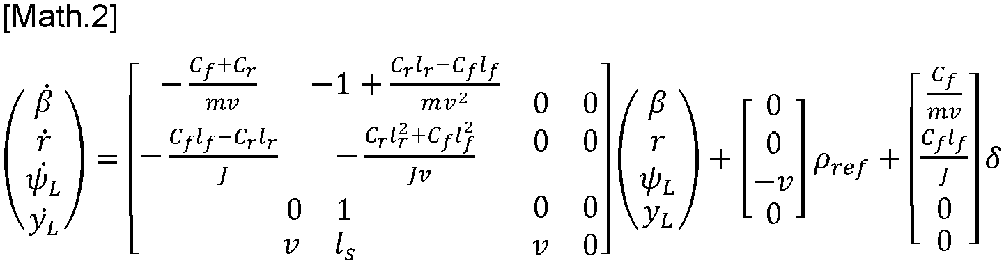
- ⁇ ⁇ r ⁇ ⁇ ⁇ L y ⁇ L ⁇ C f + C r mv ⁇ 1 + C r l r ⁇ C f l f mv 2 ⁇ C f l f ⁇ C r l r J ⁇ C r l r 2 + C f l f 2 Jv 0 0 0 0 0 1 v l s 0 0 v 0 ⁇ r ⁇ L y L + 0 0 ⁇ v 0 ⁇ ref + C f mv C f l f J 0 0 ⁇ + ⁇ 1 ⁇ + C r mv ⁇ C r l r J 0 0 ⁇ 2 ⁇
- the coefficient ⁇ corresponds to the difference between the variables ⁇ K and ⁇ ref .
- the coefficient ⁇ is a constant between 0 and infinity, which is the only parameter allowing to play on the fast or flexible character of the steering speed limiter.
- This steering speed limiter thus has the advantage of being simple to develop since it is sufficient to adjust the coefficient ⁇ . It ensures continuous and smooth control (infinitely derivable).
- This equation is characteristic of a state representation and it shows that the setpoint variation limiter model is linear as a function of the parameter ⁇ .
- the K Fbck controller which is of the "feedback" type (or closed loop) is used to determine the first component ⁇ Fbck in order to guarantee the stability and robustness of the closed loop.
- the correction term (calculated in open loop or "feed-forward") is used to determine the second component ⁇ Ffwd in order to compensate for the effects of the road curvature and the roll (induced by the road curvature) on the nominal performance of the K Fbck controller.
- ⁇ Fbck k ⁇ k r k ⁇ L k e y L k ⁇ ⁇ k ⁇ k y ⁇ L _ ref k ⁇ ref ⁇ r ⁇ L e y L ⁇ ⁇ ⁇ y ⁇ L _ ref ⁇ ref
- k ⁇ , k r , k ⁇ L , k e y L , k ⁇ , k ⁇ L_ref and k ⁇ ref are the "gains" of the K Fbck controller.
- This K Fbck controller is calculated with the assumption that curvature and roll are negligible.
- the global controller is separated into two parts: on the one hand, the "feedback" which guarantees stability and reference trajectory tracking in the nominal case (without the effect of curvature), and, on the other hand, the "feed-forward” compensates for the effect of curvature to have the iso performance (as in a case of a road without curvature).
- C y is the identity matrix
- A is a dynamic matrix
- B u is a control matrix
- B w is a perturbation matrix, which can be written in the form:
- A ⁇ C f + C r mV ⁇ 1 + C r l r ⁇ C f l f mV 2 0 0 0 C f mV 0 0 ⁇ C f l f ⁇ C r l r J ⁇ C r l r 2 + C f l f 2 JV 0 0 0 0 0 C f l f J 0 0 0 1 0 0 0 0 0 0 V l s V 0 0 0 ⁇ 1 0 0 0 0 0 0 0 0 0 0 0 0 0 0 V l s V 0 0 0 ⁇ 1 0 0 0 0 0 0 0 0 ⁇ 2
- the method used here is that of linear matrix inequalities. It is thus carried out from convex optimization criteria under constraints of linear matrix inequalities.
- the objective is more precisely to optimize the gains of the closed loop defined by the K Fbck controller by playing on the choice of poles.
- the vehicle speed is assumed to be constant (so all matrices in the system are considered constant).
- the invention then proposes to calculate the second component ⁇ Ffwd to compensate for the effect of the curvature and that of the roll in order to maintain a good level of tracking of the avoidance trajectory T0.
- This second component ⁇ Ffwd can be calculated during each avoidance phase or only for those occurring on curved roads (when the radius of curvature of the road is less than a predetermined threshold), the curvature of the road being for example derived from data perceived by a camera.
- ⁇ Ffwd l f + l r 1 ⁇ k ⁇ ⁇ k ⁇ ref + k ⁇ L ⁇ k ⁇ l r + k ⁇ L l s ⁇ k r V + K V V 2 .
- This understeer gradient is a coefficient which makes it possible to express and quantify the tendency of the motor vehicle to understeer in a bend at a given speed.
- the computer 13 is here programmed to implement this process recursively, that is to say step by step, and in a loop.
- the computer 13 plans an avoidance trajectory T0 to avoid this obstacle 20.
- the computer 13 will then seek to define a control instruction for the power steering actuator 31, namely the saturated steering angle instruction ⁇ ref , allowing this avoidance trajectory T0 to be followed as best as possible.
- the calculator 13 then calculates the gains of the controller K Fbck , then it deduces the value of the first component ⁇ Fbck of the unsaturated steering angle setpoint ⁇ K .
- the latter is then transmitted to the power steering actuator 31 in order to deviate the vehicle from its initial trajectory.
Landscapes
- Engineering & Computer Science (AREA)
- Transportation (AREA)
- Mechanical Engineering (AREA)
- Automation & Control Theory (AREA)
- Physics & Mathematics (AREA)
- Mathematical Physics (AREA)
- Chemical & Material Sciences (AREA)
- Combustion & Propulsion (AREA)
- Steering Control In Accordance With Driving Conditions (AREA)
- Control Of Driving Devices And Active Controlling Of Vehicle (AREA)
Description
La présente invention concerne de manière générale l'automatisation du suivi de trajectoires de véhicules automobiles.The present invention relates generally to the automation of the tracking of motor vehicle trajectories.
Elle trouve une application particulièrement avantageuse dans le cadre des aides à la conduite de véhicules automobiles.It finds a particularly advantageous application in the context of driving aids for motor vehicles.
Elle concerne plus particulièrement un procédé de pilotage automatisé d'un véhicule automobile permettant à ce véhicule de suivre une trajectoire d'évitement d'obstacle, notamment dans un virage.It relates more particularly to a method of automated piloting of a motor vehicle allowing this vehicle to follow an obstacle avoidance trajectory, in particular on a bend.
Elle concerne aussi un véhicule automobile équipé d'un calculateur adapté à mettre en œuvre ce procédé.It also concerns a motor vehicle equipped with a computer suitable for implementing this process.
Dans un souci de sécurisation des véhicules automobiles, on équipe actuellement ces derniers de systèmes d'aide à la conduite ou de systèmes de conduite autonome.In order to make motor vehicles safer, they are currently being equipped with driver assistance systems or autonomous driving systems.
Parmi ces systèmes, on connait notamment les systèmes de freinage d'urgence automatique (plus connu sous l'abréviation AEB, de l'anglais « Automatic Emergency Braking »), conçus pour éviter toute collision avec des obstacles situés dans la voie empruntée par le véhicule. Ces systèmes sont conçus pour détecter un obstacle sur la voie et pour agir, dans cette situation, sur le système de freinage conventionnel du véhicule automobile.Among these systems, we know in particular the automatic emergency braking systems (better known by the abbreviation AEB, from the English "Automatic Emergency Braking"), designed to avoid any collision with obstacles located in the lane taken by the vehicle. These systems are designed to detect an obstacle on the lane and to act, in this situation, on the conventional braking system of the motor vehicle.
Il existe toutefois des situations dans lesquelles ces systèmes de freinage d'urgence ne permettent pas d'éviter la collision ou ne sont pas utilisables (par exemple si un autre véhicule suit de trop près le véhicule automobile).There are, however, situations in which these emergency braking systems do not prevent a collision or cannot be used (for example, if another vehicle is following too closely behind the motor vehicle).
Pour ces situations, il a été développé des systèmes d'évitement automatique (plus connu sous l'abréviation AES, de l'anglais « Automatic Evasive Steering » ou « Automatic Emergency Steering ») qui permettent d'éviter l'obstacle en déviant le véhicule de sa trajectoire, en agissant sur la direction du véhicule.For these situations, automatic avoidance systems (better known by the abbreviation AES, from the English "Automatic Evasive Steering" or "Automatic Emergency Steering") have been developed which allow the obstacle to be avoided by diverting the vehicle from its trajectory, by acting on the direction of the vehicle.
Il arrive toutefois que ce système AES, après avoir calculé une trajectoire à suivre pour éviter l'obstacle, ne permette pas de guider le véhicule avec la précision souhaitée, ce qui peut s'avérer très dangereux.However, it happens that this AES system, after having calculated a trajectory to follow to avoid the obstacle, does not allow the vehicle to be guided with the desired precision, which can be very dangerous.
Le document
Plus précisément, ce document propose de calculer une consigne de pilotage qui minimise l'écart entre la trajectoire de véhicule et la trajectoire souhaitée. La commande utilisée à cet effet comporte une partie en boucle fermée de rétroaction et une partie en boucle ouverte, laquelle tient compte d'un facteur de perturbation de la route déterminé de façon prédictive.More specifically, this paper proposes to calculate a steering instruction that minimizes the deviation between the vehicle trajectory and the desired trajectory. The control used for this purpose comprises a closed-loop feedback part and an open-loop part, which takes into account a predictively determined road disturbance factor.
Mais même en utilisant cette solution technique, le suivi de trajectoire n'est pas aussi précis que souhaité. Les documents
Afin de remédier à l'inconvénient précité de l'état de la technique, la présente invention propose de résoudre le problème de suivi de trajectoire d'évitement en tenant compte du roulis et/ou de l'accélération latérale subi par le véhicule, lesquels ont un impact important sur la trajectoire empruntée par le véhicule.In order to overcome the aforementioned drawback of the state of the art, the present invention proposes to solve the problem of following the avoidance trajectory by taking into account the rolling and/or lateral acceleration undergone by the vehicle, which have a significant impact on the trajectory taken by the vehicle.
Plus particulièrement, on propose selon l'invention un procédé de pilotage automatisé d'un véhicule automobile, comportant des étapes de :
- acquisition de paramètres relatifs à une trajectoire d'évitement d'un obstacle par le véhicule automobile,
- acquisition d'une accélération latérale ou d'un angle de roulis subi par le véhicule automobile,
- calcul par un calculateur d'une consigne provisoire de pilotage d'un actionneur de braquage des roues directrices, en fonction desdits paramètres et au moyen d'un contrôleur en boucle fermée, et
- calcul en boucle ouverte d'un terme de correction de ladite consigne provisoire de pilotage, en fonction de l'accélération latérale ou de l'angle de roulis acquis.
- acquisition of parameters relating to an obstacle avoidance trajectory by the motor vehicle,
- acquisition of lateral acceleration or a roll angle experienced by the motor vehicle,
- calculation by a computer of a provisional instruction for controlling a steering wheel steering actuator, as a function of said parameters and by means of a closed-loop controller, and
- open-loop calculation of a correction term for said provisional piloting instruction, as a function of the lateral acceleration or the roll angle acquired.
Ainsi, le contrôleur en boucle fermée comporte un retour d'état statique calculé depuis les variables d'état du véhicule et de la route à un instant t, sans avoir à réaliser aucune prédiction qui serait source d'erreur.Thus, the closed-loop controller includes a static state feedback calculated from the vehicle and road state variables at a time t, without having to make any prediction which would be a source of error.
Le terme de correction en boucle ouverte est ensuite calculé en fonction du roulis du véhicule ou de l'accélération latérale, pour prendre en compte l'effet du roulis sur la trajectoire. Ce roulis ou cette accélération latérale peut être mesuré ou calculé.The open-loop correction term is then calculated based on vehicle roll or lateral acceleration, to account for the effect of roll on the trajectory. This roll or lateral acceleration can be measured or calculated.
Le terme de correction peut également être calculé en fonction de la courbure de route et des gains du contrôleur en boucle fermée.The correction term can also be calculated based on the road curvature and the closed-loop controller gains.
Ainsi, d'autres caractéristiques avantageuses et non limitatives du procédé conforme à l'invention, prises individuellement ou selon toutes les combinaisons techniquement possibles, sont les suivantes :
- le terme de correction est calculé en fonction d'un coefficient de braquage induit par le roulis du véhicule automobile sur les roues avant du véhicule automobile et/ou d'un coefficient de braquage induit par le roulis du véhicule automobile sur les roues arrière du véhicule automobile ;
- le terme de correction est calculé en fonction de la courbure de la route empruntée par le véhicule automobile ;
- le terme de correction est égal à la somme du produit d'une première variable multipliée par l'accélération latérale ou par l'angle de roulis, et du produit d'une seconde variable multipliée par la courbure de la route ;
- le terme de correction est calculé en fonction d'au moins l'un des gains du contrôleur en boucle fermée :
- le terme de correction est calculé en fonction d'un gradient de sous-virage ;
- le gradient de sous-virage est calculé en fonction d'au moins l'un des gains du contrôleur en boucle fermée ;
- le gradient de sous-virage est calculé au moyen de l'équation suivante :

- où m, Cf, Cr, lf, lr sont des paramètres liés uniquement à l'architecture du véhicule automobile, et
- où kδ, kδref, KΨL et kβ sont des gains du contrôleur en boucle fermée ;
- le terme de correction est calculé au moyen de l'équation suivante :

- lf, lr sont des paramètres liés uniquement à l'architecture du véhicule automobile,
- V est la vitesse longitudinale du véhicule automobile,
- ls est une distance de visée prédéterminée,
- ρref est le rayon de courbure de la route au niveau du véhicule automobile,
- ε1 est le coefficient de braquage induit par le roulis sur le train de roues avant,
- ε2 est le coefficient de braquage induit par le roulis sur le train de roues arrière,
- Φ est l'angle de roulis,
- Kv est le gradient de sous-virage,
- kδ, kδref, kΨL, kr, et kβ sont des gains du contrôleur en boucle fermée.
- the correction term is calculated based on a steering coefficient induced by the rolling of the motor vehicle on the front wheels of the motor vehicle and/or a steering coefficient induced by the rolling of the motor vehicle on the rear wheels of the motor vehicle;
- the correction term is calculated based on the curvature of the road taken by the motor vehicle;
- the correction term is equal to the sum of the product of a first variable multiplied by the lateral acceleration or by the roll angle, and the product of a second variable multiplied by the curvature of the road;
- the correction term is calculated based on at least one of the closed-loop controller gains:
- the correction term is calculated based on an understeer gradient;
- the understeer gradient is calculated based on at least one of the closed-loop controller gains;
- the understeer gradient is calculated using the following equation:
- where m, C f , C r , l f , l r are parameters related only to the architecture of the motor vehicle, and
- where k δ , k δref , K ΨL and k β are gains of the closed-loop controller;
- the correction term is calculated using the following equation:
- l f , l r are parameters linked only to the architecture of the motor vehicle,
- V is the longitudinal speed of the motor vehicle,
- l s is a predetermined aiming distance,
- ρ ref is the radius of curvature of the road at the level of the motor vehicle,
- ε 1 is the steering coefficient induced by the roll on the front wheel set,
- ε 2 is the steering coefficient induced by the roll on the rear wheel set,
- Φ is the roll angle,
- Kv is the understeer gradient,
- k δ , k δref , k ΨL , k r , and k β are gains of the closed-loop controller.
L'invention propose également un véhicule automobile comprenant un actionneur de braquage des roues directrices et un calculateur pour piloter ledit actionneurs, programmé pour mettre en oeuvre un procédé tel que précité.The invention also proposes a motor vehicle comprising an actuator for steering the steered wheels and a computer for controlling said actuator, programmed to implement a method as mentioned above.
Bien entendu, les différentes caractéristiques, variantes et formes de réalisation de l'invention peuvent être associées les unes avec les autres selon diverses combinaisons dans la mesure où elles ne sont pas incompatibles ou exclusives les unes des autres.Of course, the various features, variants and embodiments of the invention can be combined with each other in various ways. combinations to the extent that they are not incompatible or mutually exclusive.
La description qui va suivre en regard des dessins annexés, donnés à titre d'exemples non limitatifs, fera bien comprendre en quoi consiste l'invention et comment elle peut être réalisée.The description which follows with reference to the attached drawings, given as non-limiting examples, will make it clear what the invention consists of and how it can be implemented.
Sur les dessins annexés :
- [
Fig. 1 ] est une vue schématique de dessus d'un véhicule automobile circulant sur une route, sur laquelle la trajectoire que ce véhicule doit emprunter est représentée ; - [
Fig. 2 ] est une vue schématique de dessus du véhicule automobile de lafigure 1 , représenté dans quatre positions successives situées le long d'une trajectoire d'évitement d'un obstacle ; - [
Fig. 3 ] est une vue schématique de dessus du véhicule automobile de lafigure 1 , permettant d'observer l'influence du roulis sur la trajectoire du véhicule ; - [
Fig. 4 ] est un graphique illustrant les paramètres permettant de stabiliser une fonction de transfert en boucle fermée utilisée dans le cadre d'un procédé conforme à l'invention ; - [
Fig. 5 ] est un schéma bloc qui illustre les différents algorithmes permettant de mettre en œuvre le procédé conforme à l'invention ; - [
Fig. 6 ] est un schéma illustrant une fonction de transfert utilisée pour mettre en œuvre un procédé conforme à l'invention.
- [
Fig. 1 ] is a schematic top view of a motor vehicle traveling on a road, on which the trajectory that this vehicle must take is shown; - [
Fig. 2 ] is a schematic top view of the motor vehicle of thefigure 1 , represented in four successive positions located along an obstacle avoidance trajectory; - [
Fig. 3 ] is a schematic top view of the motor vehicle of thefigure 1 , allowing to observe the influence of rolling on the trajectory of the vehicle; - [
Fig. 4 ] is a graph illustrating the parameters for stabilizing a closed-loop transfer function used in a method according to the invention; - [
Fig. 5 ] is a block diagram which illustrates the different algorithms making it possible to implement the method according to the invention; - [
Fig. 6 ] is a diagram illustrating a transfer function used to implement a method according to the invention.
Sur la
Ce véhicule automobile 10 comporte au moins un système de direction conventionnel permettant d'agir sur l'orientation des roues avant 11 de façon à pouvoir faire tourner le véhicule. Ce système de direction conventionnel comprend notamment un volant connecté à des biellettes afin de faire pivoter les roues avant 11. Dans l'exemple considéré, il comporte également un actionneur 31 (représenté sur la
En complément, ce véhicule automobile pourrait également comporter un système de freinage différentiel permettant d'agir différemment sur les deux roues avant 11 (voire aussi sur les deux roues arrière 12) de façon à ralentir le véhicule automobile en le faisant tourner. Un tel système de freinage différentiel comprend par exemple un différentiel piloté ou des moteurs électriques placés au niveau des roues du véhicule ou encore des étriers de freinage pilotés indépendamment les uns des autres. Il comporte ainsi au moins un actionneur qui est conçu pour agir différemment sur les vitesses de rotation des roues en fonction d'une requête reçue du calculateur 13.In addition, this motor vehicle could also include a differential braking system making it possible to act differently on the two front wheels 11 (or even on the two rear wheels 12) so as to slow down the motor vehicle in rotating it. Such a differential braking system comprises, for example, a controlled differential or electric motors placed at the wheels of the vehicle or even brake calipers controlled independently of each other. It thus comprises at least one actuator which is designed to act differently on the rotation speeds of the wheels depending on a request received from the
On considérera ici, pour la clarté de l'exposé, que le véhicule est dépourvu d'un tel système de freinage différentiel. S'il en était pourvu, cela nécessiterait une adaptation de la loi de commande décrite ci-après.For the sake of clarity, it will be assumed here that the vehicle does not have such a differential braking system. If it were equipped with one, this would require an adaptation of the control law described below.
Le calculateur 13 est prévu pour piloter l'actionneur 31 de direction assistée en fonction des conditions de circulation rencontrées. Il comporte à cet effet au moins un processeur, au moins une mémoire et une interface d'entrée et de sortie connectée à un réseau de données du véhicule (typiquement un réseau CAN).The
Grâce à son interface, le calculateur 13 est adapté à recevoir des signaux d'entrée provenant de différents capteurs.Thanks to its interface, the
Parmi ces capteurs, il est par exemple prévu :
- un dispositif tel qu'une caméra frontale, permettant de repérer la position du véhicule par rapport à sa voie de circulation,
- un dispositif tel qu'un télédétecteur RADAR ou LIDAR, permettant de détecter
un obstacle 20 se trouvant sur la trajectoire du véhicule automobile 10 (figure 2 ), - au moins un dispositif de détection latéral, tel qu'un télédétecteur RADAR ou LIDAR, permettant d'observer l'environnement sur les côtés du véhicule,
- un dispositif tel qu'un gyromètre, permettant de déterminer la vitesse de rotation en lacet (autour d'un axe vertical) du véhicule
automobile 10, - un capteur de position et de vitesse angulaire du volant, et
- un capteur de couple appliqué par le conducteur sur le volant.
- a device such as a front camera, allowing the position of the vehicle to be located in relation to its lane,
- a device such as a RADAR or LIDAR remote sensor, making it possible to detect an
obstacle 20 located in the path of the motor vehicle 10 (figure 2 ), - at least one lateral detection device, such as a RADAR or LIDAR remote sensor, for observing the environment on the sides of the vehicle,
- a device such as a gyrometer, making it possible to determine the yaw rotation speed (around a vertical axis) of the
motor vehicle 10, - a steering wheel position and angular velocity sensor, and
- a torque sensor applied by the driver to the steering wheel.
Grâce à son interface, le calculateur 13 est adapté à transmettre une consigne à l'actionneur 31 de direction assistée.Thanks to its interface, the
Il permet ainsi de forcer le véhicule à suivre une trajectoire d'évitement T0 de l'obstacle 20 (voir
Grâce à sa mémoire, le calculateur 13 mémorise des données utilisées dans le cadre du procédé décrit ci-dessous.Using its memory, the
Il mémorise notamment une application informatique, constituée de programmes d'ordinateur comprenant des instructions dont l'exécution par le processeur permet la mise en œuvre par le calculateur du procédé décrit ci-après.In particular, it stores a computer application, consisting of computer programs comprising instructions whose execution by the processor allows the computer to implement the method described below.
Avant de décrire ce procédé, on peut introduire les différentes variables et données qui seront utilisées, dont certaines sont illustrées sur la
On considéra tout d'abord un repère (CG, X, Y, Z) attaché au véhicule, dont l'origine est située au centre de gravité du véhicule, dont l'axe X se confond avec l'axe longitudinal A1 du véhicule (en allant de l'arrière vers l'avant), dont l'axe Y est un axe latéral (allant ici de droite à gauche), et dont l'axe Z est un axe vertical lorsque le véhicule se trouve sur une route horizontale.We first considered a reference point (CG, X, Y, Z) attached to the vehicle, whose the origin is located at the center of gravity of the vehicle, whose X axis coincides with the longitudinal axis A1 of the vehicle (going from rear to front), whose Y axis is a lateral axis (going here from right to left), and whose Z axis is a vertical axis when the vehicle is on a horizontal road.
La masse totale du véhicule automobile sera notée « m » et sera exprimée en kg.The total mass of the motor vehicle will be noted “m” and will be expressed in kg.
L'inertie du véhicule automobile autour de l'axe Z sera notée « J » ou « Iz » et sera exprimée en N.m.The inertia of the motor vehicle around the Z axis will be noted “J” or “I z ” and will be expressed in Nm
L'inertie du véhicule automobile autour de l'axe X sera notée Ix et sera exprimée en N.m.The inertia of the motor vehicle around the X axis will be noted I x and will be expressed in Nm
La distance entre le centre de gravité CG et l'essieu avant du véhicule sera notée « lf » et sera exprimée en mètres.The distance between the centre of gravity CG and the front axle of the vehicle will be noted “l f ” and will be expressed in metres.
La distance entre le centre de gravité CG et l'essieu arrière sera notée « lr » et sera exprimée en mètres.The distance between the center of gravity CG and the rear axle will be noted “l r ” and will be expressed in meters.
Le coefficient de rigidité de dérive des roues avant sera noté « Cr » et sera exprimé en N/rad.The front wheel drift stiffness coefficient will be noted “C r ” and will be expressed in N/rad.
Le coefficient de rigidité de dérive des roues arrière sera noté « Cr » et sera exprimé en N/rad.The rear wheel drift stiffness coefficient will be noted “C r ” and will be expressed in N/rad.
Ces coefficients de rigidité de dérive des roues sont des notions bien connues de l'homme du métier. A titre d'exemple, le coefficient de rigidité de dérive des roues avant est ainsi celui qui permet d'écrire l'équation Fr = 2.Cf.αf, avec Ff la force latérale de glissement des roues avant et αf l'angle de dérive des roues avant.These wheel drift stiffness coefficients are concepts well known to those skilled in the art. For example, the front wheel drift stiffness coefficient is thus the one that allows the equation F r = 2.C f .α f to be written, with F f the lateral sliding force of the front wheels and α f the front wheel drift angle.
L'angle de braquage que font les roues avant directrices avec l'axe longitudinal A1 du véhicule automobile 10 sera noté « δ » et sera exprimé en rad.The steering angle that the front steered wheels make with the longitudinal axis A1 of the
La variable δref, exprimée en rad, désignera la consigne saturée d'angle de braquage, telle qu'elle sera transmise à l'actionneur de direction assistée.The variable δ ref , expressed in rad, will designate the saturated steering angle setpoint, as it will be transmitted to the power steering actuator.
La variable δK, exprimée en rad, désignera la consigne non saturée d'angle de braquage. A ce stade, on pourra seulement préciser que le concept de saturation sera lié à des limites de valeur ou de variation de valeur.The variable δ K , expressed in rad, will designate the unsaturated steering angle setpoint. At this stage, we can only specify that the concept of saturation will be linked to value limits or value variation.
La vitesse de lacet du véhicule (autour de l'axe vertical passant par son centre de gravité CG) sera notée « r » et sera exprimée en rad/s.The vehicle's yaw rate (around the vertical axis passing through its center of gravity CG) will be noted "r" and will be expressed in rad/s.
L'angle relatif de cap entre l'axe longitudinal A1 du véhicule et la tangente à la trajectoire d'évitement T0 (trajectoire souhaitée du véhicule) sera noté « ΨL » et sera exprimé en rad.The relative heading angle between the longitudinal axis A1 of the vehicle and the tangent to the avoidance trajectory T0 (desired trajectory of the vehicle) will be noted “Ψ L ” and will be expressed in rad.
L'écart latéral entre l'axe longitudinal A1 du véhicule automobile 10 (passant par le centre de gravité CG) et la trajectoire d'évitement T0, à une distance de visée « Is » située à l'avant du véhicule, sera noté « yL » et sera exprimé en mètres.The lateral deviation between the longitudinal axis A1 of the motor vehicle 10 (passing through the centre of gravity CG) and the avoidance trajectory T0, at a sighting distance “Is” located in front of the vehicle, will be noted “y L ” and will be expressed in metres.
La consigne d'écart latéral entre l'axe longitudinal A1 du véhicule automobile 10 (passant par le centre de gravité CG) et la trajectoire d'évitement T0, à une distance de visée « Is » située à l'avant du véhicule, sera notée « yL-ref » et sera exprimée en mètres.The lateral deviation instruction between the longitudinal axis A1 of the motor vehicle 10 (passing through the centre of gravity CG) and the avoidance trajectory T0, at a sighting distance “Is” located in front of the vehicle, will be noted “y L-ref ” and will be expressed in metres.
L'erreur de suivi de trajectoire sera notée « eyL » et sera exprimée en mètres. Elle sera égale à la différence entre la consigne d'écart latéral yL-ref et l'écart latéral yL.The trajectory tracking error will be noted as “e yL ” and will be expressed in meters. It will be equal to the difference between the lateral deviation setpoint y L-ref and the lateral deviation y L .
La distance de visée « Is » précitée sera mesurée à partir du centre de gravité CG et s'exprimera en mètres.The aforementioned aiming distance “Is” will be measured from the center of gravity CG and will be expressed in meters.
L'angle de dérive du véhicule automobile 10 (angle que fait le vecteur vitesse du véhicule automobile avec son axe longitudinal A1) sera noté « β » et sera exprimé en rad.The drift angle of the motor vehicle 10 (angle that the speed vector of the motor vehicle makes with its longitudinal axis A1) will be noted “β” and will be expressed in rad.
La vitesse du véhicule automobile selon l'axe longitudinal A1 sera notée « V » et s'exprimera en m/s.The speed of the motor vehicle along the longitudinal axis A1 will be noted “V” and will be expressed in m/s.
La constante « g » sera l'accélération de la pesanteur, exprimée en m.s-2.The constant "g" will be the acceleration of gravity, expressed in ms -2 .
L'angle de roulis pris par le véhicule par rapport à la verticale, exprimé en radians, sera noté Φ.The roll angle taken by the vehicle relative to the vertical, expressed in radians, will be noted Φ.
Dans le cadre du calcul de cet angle de roulis, on pourra considérer les paramètres suivants :
- br est le coefficient d'amortissement de roulis, exprimé en N.rad-1.s-1,
- kr est la raideur de roulis, exprimé en N.rad-1,
- h est la distance entre le centre de roulis du véhicule et le sol.
- b r is the roll damping coefficient, expressed in N.rad -1 .s -1 ,
- k r is the roll stiffness, expressed in N.rad -1 ,
- h is the distance between the vehicle's roll center and the ground.
L'accélération latérale subie par le véhicule selon l'axe Y sera notée ay et sera exprimée en m.s-2 .The lateral acceleration experienced by the vehicle along the Y axis will be noted a y and will be expressed in ms -2 .
La courbure moyenne de la route au niveau du véhicule automobile sera notée ρref et s'exprimera en m-1. Cette courbure est égale à l'inverse du rayon de courbure d'un l'arc-de-cercle qui est formé par la route au niveau précis du centre de gravité du véhicule automobile.The average curvature of the road at the level of the motor vehicle will be noted ρ ref and will be expressed in m -1 . This curvature is equal to the inverse of the radius of curvature of an arc of a circle which is formed by the road at the precise level of the center of gravity of the motor vehicle.
Les constantes « ξ » et « ω » représenteront des caractéristiques dynamiques de l'angle de braquage des roues avant du véhicule, plus précisément ξ représente l'amortissement et ω est la fréquence naturelle de la direction assistée électrique (DAE).The constants “ξ” and “ω” will represent dynamic characteristics of the steering angle of the front wheels of the vehicle, more precisely ξ represents the damping and ω is the natural frequency of the electric power steering (EPS).
La constante « ωf » représentera quant à elle une caractéristique dynamique d'une perturbation arbitraire « w » bornée appliquée au véhicule.The constant “ω f ” will represent a dynamic characteristic of an arbitrary limited disturbance “w” applied to the vehicle.
La vitesse de braquage désignera la vitesse angulaire de braquage des roues avant directrices.The steering speed will designate the angular steering speed of the front steered wheels.
A titre d'hypothèse, pour la clarté de l'exposé, la route sur laquelle évolue le véhicule automobile est supposée plate et horizontale.As a hypothesis, for the sake of clarity, the road on which the motor vehicle is traveling is assumed to be flat and horizontal.
Avant de décrire le procédé qui sera exécuté par le calculateur 13 pour mettre en oeuvre l'invention, on pourra décrire les calculs qui ont permis d'établir les algorithmes permettant de mettre en oeuvre l'invention, de façon à bien comprendre d'où proviennent ces algorithmes et sur quels ressorts ils s'appuient.Before describing the method that will be executed by the
A titre liminaire, on notera ici que, pour simplifier l'exposé, seule la direction assistée sera utilisée pour faire dévier le véhicule de sa trajectoire initiale. Le freinage différentiel ne sera pas installé ou activé.As a preliminary point, it should be noted here that, to simplify the presentation, only the power steering will be used to deviate the vehicle from its initial trajectory. Differential braking will not be installed or activated.
Sur la
En résumé, il est prévu que le contrôleur détermine une trajectoire à suivre, détermine une première consigne d'angle de braquage (ci-après appelée consigne non saturée d'angle de braquage δK) compte tenu de cette trajectoire et de paramètres liés à la dynamique du véhicule, puis sature cette consigne afin d'obtenir la consigne saturée d'angle de braquage δref à transmettre à l'actionneur 31.In summary, it is expected that the controller determines a trajectory to follow, determines a first steering angle setpoint (hereinafter called the unsaturated steering angle setpoint δ K ) taking into account this trajectory and parameters related to the dynamics of the vehicle, then saturates this setpoint in order to obtain the saturated steering angle setpoint δ ref to be transmitted to the
Sur la
L'obstacle 20 peut être dans la même voie que celle du véhicule automobile 10 ou dans la voie adjacente, pour autant qu'il se trouve sur la trajectoire initiale du véhicule à une distance faible compte tenu de la vitesse du véhicule.The
La façon de déterminer cette trajectoire d'évitement T0 ne faisant pas l'objet de la présente invention, elle ne sera pas ici décrite. On retiendra seulement que ce bloc Z1 permet de déterminer, lorsque la fonction AES est activée, une consigne d'écart latéral yL-ref et sa dérivée temporelle. On notera que cette trajectoire d'évitement T0 sera ici considérée comme statique mais qu'en variante, une trajectoire dynamique (recalculée en fonction de nouveaux obstacles détectés ou en fonction de la trajectoire effective du véhicule) pourrait être employée.Since the manner of determining this avoidance trajectory T0 is not the subject of the present invention, it will not be described here. It will only be noted that this block Z1 makes it possible to determine, when the AES function is activated, a lateral deviation instruction y L-ref and its time derivative. It will be noted that this avoidance trajectory T0 will here be considered as static but that as a variant, a dynamic trajectory (recalculated according to new obstacles detected or according to the actual trajectory of the vehicle) could be used.
Le bloc Z6 illustre le contrôleur KFbck qui serait utilisable et fiable si le véhicule automobile 10 roulait en ligne droite. Ce contrôleur correspond à un opérateur mathématique permettant de calculer une consigne provisoire d'angle de braquage (ci-après appelée première composante δFbck de la consigne non saturée d'angle de braquage δK) permettant de piloter les roues du véhicule de manière que ce dernier suive la trajectoire d'évitement T0.Block Z6 illustrates the controller K Fbck that would be usable and reliable if the
Les blocs Z2, Z3 et Z4 illustrent des algorithmes qui permettent de calculer un terme de correction à appliquer à la première composante δFbck pour prendre en compte l'impact du roulis du véhicule sur sa trajectoire. Ce terme de correction sera ci-après appelé seconde composante δFfwd de la consigne non saturée d'angle de braquage δK.Blocks Z2, Z3 and Z4 illustrate algorithms that allow calculating a correction term to be applied to the first component δ Fbck to take into account the impact of the vehicle's roll on its trajectory. This correction term will hereinafter be called the second component δ Ffwd of the unsaturated steering angle setpoint δ K .
La somme de la première composante δFbck et de la seconde composante δFfwd permet de calculer la consigne non saturée d'angle de braquage δK.The sum of the first component δ Fbck and the second component δ Ffwd allows the calculation of the unsaturated steering angle setpoint δ K.
Le bloc Z5 illustre une contrainte que l'on souhaite appliquer à la consigne non saturée d'angle de braquage δK.Block Z5 illustrates a constraint that we wish to apply to the non-setpoint saturated with steering angle δ K .
Cette contrainte est ici une limitation de la vitesse de braquage du volant. On souhaite en effet ici que la vitesse angulaire de braquage du volant ne dépasse pas un seuil noté υ, afin de rendre le véhicule contrôlable si le conducteur devait reprendre la main sur la conduite du véhicule pendant la phase d'évitement de l'obstacle.This constraint is here a limitation of the steering wheel turning speed. In fact, we want the steering wheel turning angular speed not to exceed a threshold noted υ , in order to make the vehicle controllable if the driver had to take back control of the vehicle during the obstacle avoidance phase.
D'autres contraintes seraient envisageables. A titre d'exemple, une contrainte de saturation en amplitude de l'angle de braquage pourrait être utilisée. Mais ici, pour la clarté de l'exposé, cette seconde contrainte ne sera pas envisagée. Encore en variante, on pourrait également ne prévoir aucune contrainte.Other constraints could be envisaged. For example, a saturation constraint in the amplitude of the steering angle could be used. But here, for the sake of clarity, this second constraint will not be considered. As a further variant, one could also not provide any constraint.
Le bloc Z5 permet donc ici de fournir une consigne saturée d'angle de braquage, ci-après référencée δsat. Cette consigne saturée servant de référence pour piloter l'actionneur de direction assistée 31, elle sera aussi référencée δref.Block Z5 therefore makes it possible to provide a saturated steering angle setpoint, hereinafter referenced δ sat . This saturated setpoint serving as a reference for controlling the
On peut maintenant détailler les calculs ayant permis d'aboutir à l'invention.We can now detail the calculations that led to the invention.
Le braquage des roues avant 11 du véhicule peut être modélisé simplement par la formule mathématique suivante.
Dans un premier temps, on va considérer l'hypothèse selon laquelle la courbure de la route empruntée est nulle. Ainsi, si on ne considère pas le roulis et la courbure de la route, on peut modéliser le comportement dynamique du véhicule au moyen de l'équation suivante.
Cette modélisation du comportement du véhicule est appelée « modèle bicyclette » puisqu'elle ne tient pas compte du fait que chaque essieu du véhicule comporte non pas une, mais deux roues. Elle permet toutefois d'aboutir à une bonne modélisation de la trajectoire du véhicule en fonction de l'angle de braquage de ses roues directrices (ici les roues avant), lorsque le véhicule se trouve en ligne droite.This modeling of the vehicle's behavior is called the "bicycle model" because it does not take into account the fact that each axle of the vehicle has not one, but two wheels. However, it allows for a good modeling of the vehicle's trajectory as a function of the steering angle of its steered wheels (here the front wheels), when the vehicle is in a straight line.
Toutefois, comme le montre la
Ici, on pourra définir le roulis par un angle, ci-après appelé « angle de roulis Φ », mesurant l'angle d'inclinaison de la caisse du véhicule par la route autour de l'axe longitudinal A1 de ce véhicule.Here, we can define the roll by an angle, hereinafter called "roll angle Φ", measuring the angle of inclination of the vehicle body by the road around the axis longitudinal A1 of this vehicle.
Le coefficient de braquage induit par le roulis sur le train avant du véhicule sera noté ε1. Une fois multiplié par l'angle de roulis Φ, il permettra d'évaluer en quoi ce roulis modifie l'angle de braquage des roues avant du véhicule et donc la trajectoire T1 représentée sur la
Le coefficient de braquage induit par le roulis sur le train arrière sera noté ε2. Une fois multiplié par l'angle de roulis Φ, il permettra d'évaluer en quoi ce roulis modifie l'angle de braquage des roues arrière.The steering coefficient induced by the roll on the rear axle will be noted ε 2 . Once multiplied by the roll angle Φ, it will allow us to evaluate how this roll modifies the steering angle of the rear wheels.
Comme le montre la
Pour tenir compte de ce phénomène, le modèle bicyclette présenté ci-avant est amélioré au moyen de l'équation suivante. 
A ce stade, on pourra noter que l'angle de roulis Φ pourra être mesuré, ou estimé. Ici, il sera modélisé par l'équation suivante.
![]()
![]()
Il pourrait alors être estimé par un filtre de Kalman. Toutefois, ici, il est plus simplement estimé au bloc Z4 de la

Pour établir cette équation, on a considéré que la variation et l'accélération du roulis sont sensiblement nulles. En effet, la plupart de temps, le véhicule est plus au moins en virage établi, donc la dynamique du roulis (ses dérivés) est sensiblement nulle.To establish this equation, it was considered that the variation and acceleration of the roll are substantially zero. Indeed, most of the time, the vehicle is more or less in an established turn, so the dynamics of the roll (its derivatives) are substantially zero.
Ici, on cherche à assurer un bon suivi de trajectoire en minimisant l'erreur de suivi de trajectoire eyL, dont on rappelle qu'elle s'exprime au moyen de l'équation suivante.

Dans ce mode de réalisation de l'invention, on suppose que la dynamique de la trajectoire de référence est représentée par l'équation ci-dessous :
![]()
![]()
Le modèle bicyclette décrit jusqu'alors ne permet toutefois pas de limiter la vitesse de braquage des roues avant 11 du véhicule. Or de telles limitations s'avèrent particulièrement importantes pour assurer au conducteur du véhicule d'être en mesure de reprendre le contrôle du véhicule à tout moment.The bicycle model described so far does not, however, allow the steering speed of the
La saturation de la vitesse de braquage illustré sur la

Dans cette équation, le seuil υ est par exemple égale à 0,0491 Rad/s, ce qui correspond à 0,785 Rad/s au niveau du volant (c'est-à-dire 45°/s) si le coefficient de démultiplication de la direction est égal à 16.In this equation, the threshold υ is for example equal to 0.0491 Rad/s, which corresponds to 0.785 Rad/s at the steering wheel (i.e. 45°/s) if the steering gear ratio is equal to 16.
Comme le montre la
- une fonction de transfert en chaîne directe égale au produit du seuil υ (pour respecter la condition édictée par l'équation précitée), d'un intégrateur en 1/s, et d'un correcteur qui est une fonction de type tangente hyperbolique de Δ.α,
- une fonction de transfert en chaîne indirecte (ou « chaîne de rétroaction ») égale à un.
- a direct chain transfer function equal to the product of the threshold υ (to respect the condition stipulated by the aforementioned equation), of a 1/s integrator, and of a corrector which is a hyperbolic tangent type function of Δ.α,
- an indirect chain transfer function (or "feedback chain") equal to one.
Il reçoit en entrée la consigne non saturée d'angle de braquage δK et transmet en sortie la consigne saturée d'angle de braquage δref.It receives as input the unsaturated steering angle setpoint δ K and transmits as output the saturated steering angle setpoint δ ref .
Sur cette figure, le coefficient Δ correspond à l'écart entre les variables δK et δref. Le coefficient α est une constante comprise entre 0 et l'infini, qui est le seul paramètre permettant de jouer sur le caractère rapide ou souple du limiteur de vitesse de braquage.In this figure, the coefficient Δ corresponds to the difference between the variables δ K and δ ref . The coefficient α is a constant between 0 and infinity, which is the only parameter allowing to play on the fast or flexible character of the steering speed limiter.
Ce limiteur de vitesse de braquage a ainsi pour avantage d'être simple à mettre au point puisqu'il suffit de régler le coefficient α. Il permet d'assurer une commande continue et lisse (infiniment dérivable).This steering speed limiter thus has the advantage of being simple to develop since it is sufficient to adjust the coefficient α. It ensures continuous and smooth control (infinitely derivable).
Alors, compte tenu de la forme de ce limiteur de vitesse de braquage, on peut écrire l'équation :

On obtient ainsi un modèle de contrôlabilité du véhicule qui est pseudo-linéaire.This gives a vehicle controllability model which is pseudo-linear.
On peut effectivement introduire le paramètre θ suivant :We can actually introduce the following parameter θ:

Puis réécrire l'équation précitée sous la forme linéaire :
![]()
![]()
Cette équation est caractéristique d'une représentation d'état et elle montre que le modèle de limiteur de variation de consigne est linéaire en fonction du paramètre θ.This equation is characteristic of a state representation and it shows that the setpoint variation limiter model is linear as a function of the parameter θ.
Il est alors possible, sur cette base, de déterminer le contrôleur KFbck, dont on rappelle qu'il assure un bon suivi de la trajectoire d'évitement T0, mais qu'il ne tient pas compte du roulis pris par le véhicule.It is then possible, on this basis, to determine the controller K Fbck , which we recall ensures good monitoring of the avoidance trajectory T0, but that it does not take into account the roll taken by the vehicle.
Compte tenu des équations précitées, on peut enrichir encore le modèle bicyclette pour obtenir un nouveau modèle utilisable. Ce nouveau modèle enrichi s'écrit : 
On rappelle que l'on peut écrire.
![]()
![]()
Par cette équation, on illustre bien que la consigne de braquage non saturée δK peut être obtenue à l'aide d'un premier contrôleur KFbck et d'un terme de correction prenant en compte l'influence du roulis sur la trajectoire du véhicule.This equation clearly illustrates that the unsaturated steering instruction δ K can be obtained using a first controller K Fbck and a correction term taking into account the influence of rolling on the vehicle trajectory.
Dans un premier temps, le contrôleur KFbck, qui est de type « feedback» (ou boucle fermée), permet de déterminer la première composante δFbck de façon à garantir la stabilité et la robustesse de la boucle fermée. Dans un deuxième temps, le terme de correction (calculé en boucle ouverte ou « feed-forward ») permet de déterminer la seconde composante δFfwd afin de compenser les effets de la courbure de route et du roulis (induit par la courbure de route) sur la performance nominale du contrôleur KFbck.First, the K Fbck controller, which is of the "feedback" type (or closed loop), is used to determine the first component δ Fbck in order to guarantee the stability and robustness of the closed loop. Second, the correction term (calculated in open loop or "feed-forward") is used to determine the second component δ Ffwd in order to compensate for the effects of the road curvature and the roll (induced by the road curvature) on the nominal performance of the K Fbck controller.
On peut alors s'intéresser tout d'abord à la synthèse du contrôleur KFbck.We can then first focus on the synthesis of the K Fbck controller.
On peut écrire :We can write:

où kβ, kr, kψ![]()
where k β , k r , k ψ![]()
On peut alors considérer un vecteur d'état x, que l'on écrit sous la forme :

L'objectif est alors de déterminer la forme du contrôleur KFbck. Pour cela, on peut écrire notre modèle comportemental sous une forme générique :

Dans cette équation, Cy est la matrice identité, A est une matrice dynamique, Bu est une matrice de commande et Bw est une matrice de perturbation, que l'on peut écrire sous la forme : 
Le contrôleur KFbck, qui est défini comme un retour d'état statique, peut quant à lui s'exprimer sous la forme :
![]()
![]()
Pour trouver un contrôleur KFbck optimal, on peut utiliser différentes méthodes.To find an optimal K Fbck controller, different methods can be used.
La méthode utilisée ici est celle des inégalités matricielles linéaires. Elle est ainsi réalisée à partir de critères d'optimisation convexe sous contraintes d'inégalités matricielles linéaires.The method used here is that of linear matrix inequalities. It is thus carried out from convex optimization criteria under constraints of linear matrix inequalities.
L'objectif est plus précisément d'optimiser les gains de la boucle fermée définie par le contrôleur KFbck en jouant sur le choix des pôles.The objective is more precisely to optimize the gains of the closed loop defined by the K Fbck controller by playing on the choice of poles.
Les inéquations matricielles utilisées sont au nombre de trois et sont définies par les inéquations suivantes.


Dans ces inéquations, l'indice i est égal à 1 ou 2, et on peut alors définir les matrices Ai et Bi de la façon suivante :
![]()
![]()
Une matrice de la forme ![]()

![]()
Le contrôleur KFbck est défini par l'équation :
![]()
![]()
La vitesse du véhicule est supposée constante (donc toutes les matrices du système sont considérées constantes).The vehicle speed is assumed to be constant (so all matrices in the system are considered constant).
Les trois inéquations permettent de s'assurer que la dynamique de la boucle fermée reste limitée. En effet, grâce à ces contraintes, les pôles de la boucle fermée se retrouvent bornés dans une zone définie par un rayon γ, une distance minimale par rapport à l'axe imaginaire µ, et un angle d'ouverture ϕ (voir
Cette méthode s'avère efficace lorsqu'il s'agit de déterminer à chaque instant l'angle de volant de façon raisonnable (et maîtrisable par un conducteur aux compétences moyennes) et de manière réalisable par l'actionneur. Ces contraintes assurent également la stabilité de la boucle fermée.This method proves effective when it comes to determining the steering wheel angle at all times in a reasonable way (and controllable by a driver with average skills) and in a way that is achievable by the actuator. These constraints also ensure the stability of the closed loop.
L'objectif est ici de minimiser le rayon γ. Une fois les gains du contrôleur KFbck obtenus, on peut obtenir calculer le résultat du contrôleur au moyen de la formule suivante :

On a introduit dans les trois inéquations matricielles les valeurs θmin et θmax.The values θ min and θ max were introduced into the three matrix inequalities.
La valeur de θ, qui est lié à l'écart entre δK et δref, reflète le niveau de violation par le contrôleur KFbck de la limite de contrôlabilité énoncée par l'équation [Math.8].The value of θ, which is related to the gap between δ K and δ ref , reflects the level of violation by the controller K Fbck of the controllability limit stated by equation [Math.8].
Par définition, θ est compris entre 0 (exclu) et 1 (inclus). Lorsque θ est égal à 1, la consigne non saturée d'angle au volant δK calculée respecte bien la limite de contrôlabilité. Lorsqu'il est proche de 0, la consigne non saturée d'angle au volant δK calculée présente une valeur qui impose une trop grande dynamique de braquage, ce qui génère un risque d'instabilité du véhicule. Quand θ prend des valeurs intermédiaires entre 0 et 1, la limite de contrôlabilité n'est pas respectée mais il est possible qu'il n'y ait pas de risque d'instabilité du véhicule.By definition, θ is between 0 (exclusive) and 1 (inclusive). When θ is equal to 1, the calculated unsaturated steering wheel angle setpoint δ K respects the controllability limit. When it is close to 0, the calculated unsaturated steering wheel angle setpoint δ K has a value that imposes too great a steering dynamic, which generates a risk of vehicle instability. When θ takes intermediate values between 0 and 1, the controllability limit is not respected but it is possible that there is no risk of vehicle instability.
En d'autres termes, le choix des valeurs θmin et θmax a un impact direct sur la performance et sur la robustesse du contrôleur KFbck. Plus la plage [θmin,θmax] est grande, moins le contrôleur KFbck est performant mais plus il est robuste. Au contraire, plus cette plage est petite, plus le contrôleur KFbck est performant mais moins il est robuste.In other words, the choice of the values θ min and θ max has a direct impact on the performance and robustness of the K Fbck controller. The larger the range [θ min ,θ max ], the less efficient the K Fbck controller is but the more robust it is. On the contrary, the smaller this range, the more efficient the K Fbck controller is but the less robust it is.
Logiquement la valeur θmax est choisie égale à 1 (cas selon lequel le contrôleur KFbck fonctionne en mode linéaire, comme c'est d'ailleurs généralement le cas, sans violation de contrainte de contrôlabilité).Logically the value θ max is chosen equal to 1 (case in which the controller K Fbck operates in linear mode, as is generally the case, without violation of controllability constraints).
La détermination de la valeur θmin nécessite en revanche de faire un compromis entre performance et robustesse. La détermination de cette valeur revient à imposer un seuil maximal pour l'écart, en valeur absolue, entre δK et δref.Determining the value θ min , on the other hand, requires a compromise between performance and robustness. Determining this value involves imposing a maximum threshold for the difference, in absolute value, between δ K and δ ref .
En virage, le double effet de courbure et de roulis devient plus impactant sur la performance du contrôleur KFbck.When cornering, the dual effect of curvature and roll becomes more impactful on the performance of the K Fbck controller.
L'invention propose alors de calculer la seconde composante δFfwd pour compenser l'effet de la courbure et celle du roulis afin de maintenir un bon niveau de suivi de la trajectoire d'évitement T0.The invention then proposes to calculate the second component δ Ffwd to compensate for the effect of the curvature and that of the roll in order to maintain a good level of tracking of the avoidance trajectory T0.
Cette seconde composante δFfwd peut être calculée lors de chaque phase d'évitement ou uniquement pour celles intervenant sur des routes courbées (lorsque le rayon de courbure de la route est inférieur à un seuil prédéterminé), la courbure de la route étant par exemple issue des données perçues par une caméra.This second component δ Ffwd can be calculated during each avoidance phase or only for those occurring on curved roads (when the radius of curvature of the road is less than a predetermined threshold), the curvature of the road being for example derived from data perceived by a camera.
Comme cela apparait bien sur la
En pratique, on remplace, dans l'équation [Math.12], la consigne non saturée d'angle de braquage δK par son expression issue de l'équation [Math.13], ce qui permet d'obtenir l'équation d'un système en boucle fermée suivant.

Sachant que la perturbation wy
Pour cela, tout d'abord, on peut calculer les valeurs statiques des états du système défini par l'équation [Math.25], où les dérivés sont nulles, ce qui revient à résoudre le système d'équation suivant : 
La résolution de ce système d'équation ci-dessus permet de calculer l'erreur de suivi de trajectoire eyL statique, en fonction de la courbure ρref de la route, de la vitesse V du véhicule automobile 10, de l'angle de roulis Φ, des gains du contrôleur KFbck, de la seconde composante δFfwd recherchée, et d'autres paramètres relatifs au véhicule lui-même (lf, lr, ε1, ε2...). On peut ainsi écrire :

Alors, pour trouver la seconde composante δFfwd permettant d'obtenir une erreur de suivi de trajectoire eyL statique nulle, on peut écrire l'équation ci-dessous :

Ce qui permet d'obtenir l'équation qui suit. 
Dans cette équation, le terme Kv est appelé « gradient de sous-virage » et s'exprime ainsi :

Ce gradient de sous-virage est un coefficient qui permet d'exprimer et de quantifier la tendance du véhicule automobile à sous-virer dans un virage à une vitesse donnée.This understeer gradient is a coefficient which makes it possible to express and quantify the tendency of the motor vehicle to understeer in a bend at a given speed.
En résumé, pour obtenir la seconde composante δFfwd, il suffit donc de calculer le terme Kv au moyen de l'équation [Math.30] (bloc Z2 de la
A ce stade, on peut alors décrire le procédé qui sera exécuté par le calculateur 13 du véhicule automobile 10 pour mettre en œuvre l'invention.At this stage, we can then describe the method which will be executed by the
Le calculateur 13 est ici programmé pour mettre en œuvre ce procédé de façon récursive, c'est-à-dire pas à pas, et en boucle.The
Pour cela, au cours d'une première étape, le calculateur 13 vérifie que la fonction d'évitement autonome d'obstacle (AES) est activée.To do this, during a first step, the
Si tel est le cas, il tente de détecter la présence d'un éventuel obstacle se trouvant sur le trajet du véhicule automobile 10. Il utilise pour cela son télédétecteur RADAR ou LIDAR.If this is the case, it attempts to detect the presence of a possible obstacle located in the path of the
En l'absence d'obstacle, cette étape est répétée en boucles.In the absence of an obstacle, this step is repeated in loops.
Dès qu'un obstacle 20 potentiellement dangereux est détecté (voir
Le calculateur 13 va alors chercher à définir une consigne de pilotage de l'actionneur de direction assistée 31, à savoir la consigne saturée d'angle de braquage δref, permettant de suivre au mieux cette trajectoire d'évitement T0.The
Il commence pour cela par calculer ou acquérir des paramètres tels que :
- l'angle de braquage δ mesuré,
- l'angle de dérive β du véhicule
automobile 10, - la dérivée par rapport au temps de l'angle de braquage mesuré δ,
- la consigne saturée d'angle de braquage δref obtenue au pas de temps précédent,
- la vitesse de lacet r,
- l'angle relatif de cap ΨL, et
- la consigne d'écart latéral yL-ref.
- the measured steering angle δ,
- the drift angle β of the
motor vehicle 10, - the time derivative of the measured steering angle δ,
- the saturated steering angle setpoint δ ref obtained at the previous time step,
- the yaw rate r,
- the relative heading angle Ψ L , and
- the lateral deviation instruction y L-ref .
Comme le montre la
Il en déduit également les valeurs du terme Kv puis de la seconde composante δFfwd de la consigne d'angle de braquage non saturée δK.It also deduces the values of the term K v then of the second component δ Ffwd of the unsaturated steering angle setpoint δ K .
Il peut donc ensuite en déduire la valeur de cette consigne d'angle de braquage non saturée δK puis de celle de consigne d'angle de braquage saturée δref.He can then deduce the value of this unsaturated steering angle setpoint δ K then that of the saturated steering angle setpoint δ ref .
Cette dernière est ensuite transmise à l'actionneur de direction assistée 31 afin de dévier le véhicule de sa trajectoire initiale.The latter is then transmitted to the
La présente invention n'est nullement limitée au mode de réalisation décrit et représenté, mais l'homme du métier saura y apporter toute variante conforme à l'invention.The present invention is in no way limited to the embodiment described and shown, but those skilled in the art will be able to provide any variation in accordance with the invention.
Claims (10)
- Control method for the automated steering of a motor vehicle (10) comprising wheels (11, 12) of which at least two wheels (11) are steered wheels, comprising steps of:- acquiring parameters (β, r, ΨL, yL, δ, δref) relating to an avoidance path whereby the motor vehicle (10) avoids an obstacle (20), and of- calculating, using a computer (13) a temporary control instruction (δFbck) for a steering actuator (31) that steers the steered wheels (11), as a function of said parameters (β, r, ΨL, yL, δ, δref) and by means of a closed loop controller (KFbck),
characterized in that it further comprises steps of:- acquiring a lateral acceleration (ay) or a roll angle (Φ) experienced by the motor vehicle (10), and- calculating, using open loop calculation, a correction term (δFfwd) for said temporary control instruction (δFbck), as a function of the lateral acceleration (ay) or of the roll angle (Φ) acquired. - Control method according to the preceding claim, wherein the correction term (δFfwd) is calculated as a function of a coefficient of steering (ε1) induced by the rolling of the motor vehicle (10) on the front wheels (11) of the motor vehicle (10) and/or of a coefficient of steering (ε2) induced by the rolling of the motor vehicle (10) on the rear wheels (12) of the motor vehicle (10).
- Control method according to one of the preceding claims, wherein the correction term (δFfwd) is calculated as a function of the curvature (ρref) of the road taken by the motor vehicle (10).
- Control method according to the preceding claim, wherein the correction term (δFfwd) is equal to the sum of:- the product of a first variable multiplied by the lateral acceleration (ay) or by the roll angle (Φ), and- the product of a second variable multiplied by the curvature (ρref) of the road.
- Control method according to one of the preceding claims, wherein the correction term (δFfwd) is calculated as a function of at least one of the gains of the closed loop controller (KFbck).
- Control method according to one of the preceding claims, wherein the correction term (δFfwd) is calculated as a function of an understeer gradient (Kv).
- Control method according to the preceding claim, wherein the understeer gradient (Kv) is calculated as a function of at least one of the gains of the closed loop controller (KFbck).
- Control method according to the preceding claim, wherein the understeer gradient (Kv) is calculated by means of the following equation:
 where m, Cf, Cr, lf, lr are parameters connected only with the architecture of the motor vehicle, andwhere kδ, kδref, kΨL and kβ are gains of the closed loop controller.
 - Control method according to the preceding claims, wherein the correction term (δFfwd) is calculated by means of the following equation:
 lf, lr are parameters connected only with the architecture of the motor vehicle,V is the longitudinal velocity of the motor vehicle,ls is a predetermined sighting distance,ρref is the radius of curvature of the road at the motor vehicle,ε1 is the coefficient of steering induced by the rolling on the front wheelset,ε2 is the coefficient of steering induced by the rolling on the rear wheelset,Φ is the roll angle,Kv is the understeer gradient,kδ, kδref, kΨL, kr, and kβ are gains of the closed loop controller.
 - Motor vehicle (10) comprising a steering actuator (31) for steering the steered wheels (11) and a computer (13) for controlling said actuators (31), characterized in that the computer (13) is programmed to implement a method according to one of the preceding claims.
Applications Claiming Priority (2)
| Application Number | Priority Date | Filing Date | Title |
|---|---|---|---|
| FR2100740A FR3119140B1 (en) | 2021-01-27 | 2021-01-27 | Obstacle avoidance method |
| PCT/EP2022/051219 WO2022161845A1 (en) | 2021-01-27 | 2022-01-20 | Obstacle avoidance method |
Publications (2)
| Publication Number | Publication Date |
|---|---|
| EP4284690A1 EP4284690A1 (en) | 2023-12-06 |
| EP4284690B1 true EP4284690B1 (en) | 2025-03-05 |
Family
ID=75539501
Family Applications (1)
| Application Number | Title | Priority Date | Filing Date |
|---|---|---|---|
| EP22700841.4A Active EP4284690B1 (en) | 2021-01-27 | 2022-01-20 | Obstacle avoidance method |
Country Status (7)
| Country | Link |
|---|---|
| US (1) | US20240124055A1 (en) |
| EP (1) | EP4284690B1 (en) |
| JP (1) | JP2024504783A (en) |
| KR (1) | KR20230135634A (en) |
| CN (1) | CN116897117A (en) |
| FR (1) | FR3119140B1 (en) |
| WO (1) | WO2022161845A1 (en) |
Family Cites Families (11)
| Publication number | Priority date | Publication date | Assignee | Title |
|---|---|---|---|---|
| US5774821A (en) * | 1994-11-25 | 1998-06-30 | Itt Automotive Europe Gmbh | System for driving stability control |
| JP3637849B2 (en) * | 2000-07-06 | 2005-04-13 | 日産自動車株式会社 | Lane tracking control device |
| JP4893118B2 (en) * | 2006-06-13 | 2012-03-07 | 日産自動車株式会社 | Avoidance control device, vehicle including the avoidance control device, and avoidance control method |
| US8983765B2 (en) * | 2006-10-11 | 2015-03-17 | GM Global Technology Operations LLC | Method and system for lane centering control |
| DE102010028384A1 (en) * | 2009-05-07 | 2010-11-11 | Continental Teves Ag & Co. Ohg | Method and device for controlling or controlling the driving stability of a vehicle |
| DE102009043070B4 (en) * | 2009-09-25 | 2022-06-15 | Volkswagen Ag | Device for adjusting the rolling behavior of a motor vehicle |
| FR3041590B1 (en) * | 2015-09-30 | 2018-08-17 | Renault S.A.S | SYSTEM FOR CONTROLLING THE DIRECTION OF A MOTOR VEHICLE IN THE EVENT OF AN IMMINENT COLLISION WITH AN OBSTACLE |
| US9731755B1 (en) | 2016-02-16 | 2017-08-15 | GM Global Technology Operations LLC | Preview lateral control for automated driving |
| FR3088275B1 (en) * | 2018-11-13 | 2021-06-18 | Renault Sas | OBSTACLE AVOIDANCE PROCESS AND SYSTEM INCLUDING THE CONTROL OF THE STEERING AND DIFFERENTIAL BRAKING SYSTEMS |
| KR20200076654A (en) * | 2020-03-25 | 2020-06-29 | 주식회사 만도 | Steering control device and method, and steering device |
| CN111959500B (en) * | 2020-08-07 | 2022-11-11 | 长春工业大学 | A method for improving vehicle path tracking performance based on tire force distribution |
-
2021
- 2021-01-27 FR FR2100740A patent/FR3119140B1/en active Active
-
2022
- 2022-01-20 US US18/263,264 patent/US20240124055A1/en active Pending
- 2022-01-20 WO PCT/EP2022/051219 patent/WO2022161845A1/en not_active Ceased
- 2022-01-20 JP JP2023545820A patent/JP2024504783A/en active Pending
- 2022-01-20 EP EP22700841.4A patent/EP4284690B1/en active Active
- 2022-01-20 CN CN202280016063.9A patent/CN116897117A/en active Pending
- 2022-01-20 KR KR1020237028644A patent/KR20230135634A/en active Pending
Also Published As
| Publication number | Publication date |
|---|---|
| FR3119140A1 (en) | 2022-07-29 |
| WO2022161845A1 (en) | 2022-08-04 |
| KR20230135634A (en) | 2023-09-25 |
| JP2024504783A (en) | 2024-02-01 |
| US20240124055A1 (en) | 2024-04-18 |
| CN116897117A (en) | 2023-10-17 |
| FR3119140B1 (en) | 2023-04-14 |
| EP4284690A1 (en) | 2023-12-06 |
Similar Documents
| Publication | Publication Date | Title |
|---|---|---|
| EP3938260B1 (en) | Method for generating a setpoint for the combined control of a wheel-steering system and of a differential braking system of a motor vehicle | |
| EP1304270B1 (en) | Vehicle stability control method using tyre lateral forces and taking into account inertia of the vehicle | |
| EP4037947B1 (en) | Control device for a self-driving motor vehicle | |
| EP3344506B1 (en) | Device and method for correcting the direction of travel of a motor vehicle | |
| EP3994042B1 (en) | Method for determining an avoidance path of a motor vehicle | |
| FR3099450A1 (en) | Autonomous control method of an actuator of an automotive device | |
| EP3880526B1 (en) | Method and system for obstacle avoidance, involving the control of steering and differential braking systems | |
| EP3938259B1 (en) | Method for autonomously controlling a mobility of an apparatus | |
| FR3104107A1 (en) | Method of driving a motor vehicle | |
| EP4320026A1 (en) | Method for autonomously driving an actuator of a device | |
| WO2021079004A1 (en) | Method for controlling a wheeled vehicle in low-grip conditions | |
| EP4264390B1 (en) | Method for controlling a motor vehicle for target avoidance with clothoid trajectory refinement | |
| FR3101832A1 (en) | High level side assist controller suitable for 4RD vehicles | |
| EP2043901B1 (en) | Device and method for monitoring the turn command to a steered rear wheel | |
| WO2022112047A1 (en) | Method for automated steering of a motor vehicle | |
| WO2018036723A1 (en) | Method of stabilization by orientation of a convoy of vehicles | |
| EP4572996A1 (en) | Method for autonomously controlling an actuator of a device | |
| EP4284690B1 (en) | Obstacle avoidance method | |
| FR3135685A1 (en) | Method for autonomously controlling an automobile device | |
| FR3094324A1 (en) | Autonomous piloting method of a device trajectory control member | |
| FR3092914A1 (en) | Method for determining the trajectory of a vehicle comprising four steered wheels | |
| WO2024104837A1 (en) | Method for driving a motor vehicle in the centre of its traffic lane | |
| FR3142422A1 (en) | Method of assisting the piloting of a motor vehicle to realign it parallel to an ideal trajectory, associated device and vehicle. | |
| EP4382382A1 (en) | Method for controlling a vehicle in its lane | |
| FR3102445A1 (en) | Method for controlling a vehicle running in a precarious condition of adhesion |
Legal Events
| Date | Code | Title | Description |
|---|---|---|---|
| STAA | Information on the status of an ep patent application or granted ep patent |
Free format text: STATUS: UNKNOWN |
|
| STAA | Information on the status of an ep patent application or granted ep patent |
Free format text: STATUS: THE INTERNATIONAL PUBLICATION HAS BEEN MADE |
|
| PUAI | Public reference made under article 153(3) epc to a published international application that has entered the european phase |
Free format text: ORIGINAL CODE: 0009012 |
|
| STAA | Information on the status of an ep patent application or granted ep patent |
Free format text: STATUS: REQUEST FOR EXAMINATION WAS MADE |
|
| 17P | Request for examination filed |
Effective date: 20230727 |
|
| AK | Designated contracting states |
Kind code of ref document: A1 Designated state(s): AL AT BE BG CH CY CZ DE DK EE ES FI FR GB GR HR HU IE IS IT LI LT LU LV MC MK MT NL NO PL PT RO RS SE SI SK SM TR |
|
| RAP1 | Party data changed (applicant data changed or rights of an application transferred) |
Owner name: NISSAN MOTOR CO., LTD. Owner name: AMPERE SAS |
|
| DAV | Request for validation of the european patent (deleted) | ||
| DAX | Request for extension of the european patent (deleted) | ||
| GRAP | Despatch of communication of intention to grant a patent |
Free format text: ORIGINAL CODE: EPIDOSNIGR1 |
|
| STAA | Information on the status of an ep patent application or granted ep patent |
Free format text: STATUS: GRANT OF PATENT IS INTENDED |
|
| INTG | Intention to grant announced |
Effective date: 20240917 |
|
| RIN1 | Information on inventor provided before grant (corrected) |
Inventor name: DO, ANH-LAM |
|
| GRAS | Grant fee paid |
Free format text: ORIGINAL CODE: EPIDOSNIGR3 |
|
| GRAA | (expected) grant |
Free format text: ORIGINAL CODE: 0009210 |
|
| STAA | Information on the status of an ep patent application or granted ep patent |
Free format text: STATUS: THE PATENT HAS BEEN GRANTED |
|
| AK | Designated contracting states |
Kind code of ref document: B1 Designated state(s): AL AT BE BG CH CY CZ DE DK EE ES FI FR GB GR HR HU IE IS IT LI LT LU LV MC MK MT NL NO PL PT RO RS SE SI SK SM TR |
|
| REG | Reference to a national code |
Ref country code: GB Ref legal event code: FG4D Free format text: NOT ENGLISH |
|
| REG | Reference to a national code |
Ref country code: CH Ref legal event code: EP |
|
| REG | Reference to a national code |
Ref country code: IE Ref legal event code: FG4D Free format text: LANGUAGE OF EP DOCUMENT: FRENCH |
|
| REG | Reference to a national code |
Ref country code: DE Ref legal event code: R096 Ref document number: 602022011406 Country of ref document: DE |
|
| PG25 | Lapsed in a contracting state [announced via postgrant information from national office to epo] |
Ref country code: RS Free format text: LAPSE BECAUSE OF FAILURE TO SUBMIT A TRANSLATION OF THE DESCRIPTION OR TO PAY THE FEE WITHIN THE PRESCRIBED TIME-LIMIT Effective date: 20250605 |
|
| PG25 | Lapsed in a contracting state [announced via postgrant information from national office to epo] |
Ref country code: FI Free format text: LAPSE BECAUSE OF FAILURE TO SUBMIT A TRANSLATION OF THE DESCRIPTION OR TO PAY THE FEE WITHIN THE PRESCRIBED TIME-LIMIT Effective date: 20250305 |
|
| REG | Reference to a national code |
Ref country code: NL Ref legal event code: MP Effective date: 20250305 |
|
| PG25 | Lapsed in a contracting state [announced via postgrant information from national office to epo] |
Ref country code: ES Free format text: LAPSE BECAUSE OF FAILURE TO SUBMIT A TRANSLATION OF THE DESCRIPTION OR TO PAY THE FEE WITHIN THE PRESCRIBED TIME-LIMIT Effective date: 20250305 |
|
| REG | Reference to a national code |
Ref country code: LT Ref legal event code: MG9D |
|
| PG25 | Lapsed in a contracting state [announced via postgrant information from national office to epo] |
Ref country code: NO Free format text: LAPSE BECAUSE OF FAILURE TO SUBMIT A TRANSLATION OF THE DESCRIPTION OR TO PAY THE FEE WITHIN THE PRESCRIBED TIME-LIMIT Effective date: 20250605 |
|
| PG25 | Lapsed in a contracting state [announced via postgrant information from national office to epo] |
Ref country code: HR Free format text: LAPSE BECAUSE OF FAILURE TO SUBMIT A TRANSLATION OF THE DESCRIPTION OR TO PAY THE FEE WITHIN THE PRESCRIBED TIME-LIMIT Effective date: 20250305 |
|
| PG25 | Lapsed in a contracting state [announced via postgrant information from national office to epo] |
Ref country code: LV Free format text: LAPSE BECAUSE OF FAILURE TO SUBMIT A TRANSLATION OF THE DESCRIPTION OR TO PAY THE FEE WITHIN THE PRESCRIBED TIME-LIMIT Effective date: 20250305 |
|
| PG25 | Lapsed in a contracting state [announced via postgrant information from national office to epo] |
Ref country code: GR Free format text: LAPSE BECAUSE OF FAILURE TO SUBMIT A TRANSLATION OF THE DESCRIPTION OR TO PAY THE FEE WITHIN THE PRESCRIBED TIME-LIMIT Effective date: 20250606 Ref country code: BG Free format text: LAPSE BECAUSE OF FAILURE TO SUBMIT A TRANSLATION OF THE DESCRIPTION OR TO PAY THE FEE WITHIN THE PRESCRIBED TIME-LIMIT Effective date: 20250305 |
|
| REG | Reference to a national code |
Ref country code: AT Ref legal event code: MK05 Ref document number: 1772694 Country of ref document: AT Kind code of ref document: T Effective date: 20250305 |
|
| PG25 | Lapsed in a contracting state [announced via postgrant information from national office to epo] |
Ref country code: NL Free format text: LAPSE BECAUSE OF FAILURE TO SUBMIT A TRANSLATION OF THE DESCRIPTION OR TO PAY THE FEE WITHIN THE PRESCRIBED TIME-LIMIT Effective date: 20250305 |
|
| PG25 | Lapsed in a contracting state [announced via postgrant information from national office to epo] |
Ref country code: SE Free format text: LAPSE BECAUSE OF FAILURE TO SUBMIT A TRANSLATION OF THE DESCRIPTION OR TO PAY THE FEE WITHIN THE PRESCRIBED TIME-LIMIT Effective date: 20250305 |
|
| PG25 | Lapsed in a contracting state [announced via postgrant information from national office to epo] |
Ref country code: SM Free format text: LAPSE BECAUSE OF FAILURE TO SUBMIT A TRANSLATION OF THE DESCRIPTION OR TO PAY THE FEE WITHIN THE PRESCRIBED TIME-LIMIT Effective date: 20250305 |
|
| PG25 | Lapsed in a contracting state [announced via postgrant information from national office to epo] |
Ref country code: PT Free format text: LAPSE BECAUSE OF FAILURE TO SUBMIT A TRANSLATION OF THE DESCRIPTION OR TO PAY THE FEE WITHIN THE PRESCRIBED TIME-LIMIT Effective date: 20250707 |
|
| PG25 | Lapsed in a contracting state [announced via postgrant information from national office to epo] |
Ref country code: PL Free format text: LAPSE BECAUSE OF FAILURE TO SUBMIT A TRANSLATION OF THE DESCRIPTION OR TO PAY THE FEE WITHIN THE PRESCRIBED TIME-LIMIT Effective date: 20250305 Ref country code: IT Free format text: LAPSE BECAUSE OF FAILURE TO SUBMIT A TRANSLATION OF THE DESCRIPTION OR TO PAY THE FEE WITHIN THE PRESCRIBED TIME-LIMIT Effective date: 20250305 |
|
| PG25 | Lapsed in a contracting state [announced via postgrant information from national office to epo] |
Ref country code: AT Free format text: LAPSE BECAUSE OF FAILURE TO SUBMIT A TRANSLATION OF THE DESCRIPTION OR TO PAY THE FEE WITHIN THE PRESCRIBED TIME-LIMIT Effective date: 20250305 |
|
| PG25 | Lapsed in a contracting state [announced via postgrant information from national office to epo] |
Ref country code: EE Free format text: LAPSE BECAUSE OF FAILURE TO SUBMIT A TRANSLATION OF THE DESCRIPTION OR TO PAY THE FEE WITHIN THE PRESCRIBED TIME-LIMIT Effective date: 20250305 Ref country code: CZ Free format text: LAPSE BECAUSE OF FAILURE TO SUBMIT A TRANSLATION OF THE DESCRIPTION OR TO PAY THE FEE WITHIN THE PRESCRIBED TIME-LIMIT Effective date: 20250305 |
|
| PG25 | Lapsed in a contracting state [announced via postgrant information from national office to epo] |
Ref country code: RO Free format text: LAPSE BECAUSE OF FAILURE TO SUBMIT A TRANSLATION OF THE DESCRIPTION OR TO PAY THE FEE WITHIN THE PRESCRIBED TIME-LIMIT Effective date: 20250305 |
|
| PG25 | Lapsed in a contracting state [announced via postgrant information from national office to epo] |
Ref country code: SK Free format text: LAPSE BECAUSE OF FAILURE TO SUBMIT A TRANSLATION OF THE DESCRIPTION OR TO PAY THE FEE WITHIN THE PRESCRIBED TIME-LIMIT Effective date: 20250305 |
|
| PG25 | Lapsed in a contracting state [announced via postgrant information from national office to epo] |
Ref country code: IS Free format text: LAPSE BECAUSE OF FAILURE TO SUBMIT A TRANSLATION OF THE DESCRIPTION OR TO PAY THE FEE WITHIN THE PRESCRIBED TIME-LIMIT Effective date: 20250705 |
|
| REG | Reference to a national code |
Ref country code: DE Ref legal event code: R097 Ref document number: 602022011406 Country of ref document: DE |
|
| PLBE | No opposition filed within time limit |
Free format text: ORIGINAL CODE: 0009261 |
|
| STAA | Information on the status of an ep patent application or granted ep patent |
Free format text: STATUS: NO OPPOSITION FILED WITHIN TIME LIMIT |
|
| PG25 | Lapsed in a contracting state [announced via postgrant information from national office to epo] |
Ref country code: DK Free format text: LAPSE BECAUSE OF FAILURE TO SUBMIT A TRANSLATION OF THE DESCRIPTION OR TO PAY THE FEE WITHIN THE PRESCRIBED TIME-LIMIT Effective date: 20250305 |
|
| REG | Reference to a national code |
Ref country code: CH Ref legal event code: L10 Free format text: ST27 STATUS EVENT CODE: U-0-0-L10-L00 (AS PROVIDED BY THE NATIONAL OFFICE) Effective date: 20260114 |
|
| 26N | No opposition filed |
Effective date: 20251208 |
|
| PGFP | Annual fee paid to national office [announced via postgrant information from national office to epo] |
Ref country code: GB Payment date: 20260123 Year of fee payment: 5 |
|
| PGFP | Annual fee paid to national office [announced via postgrant information from national office to epo] |
Ref country code: DE Payment date: 20260121 Year of fee payment: 5 |
|
| PGFP | Annual fee paid to national office [announced via postgrant information from national office to epo] |
Ref country code: FR Payment date: 20260123 Year of fee payment: 5 |