EP4169544B1 - Attachment for a device for generating an air flow or for delivering a fluid into the external auditory canal - Google Patents
Attachment for a device for generating an air flow or for delivering a fluid into the external auditory canal Download PDFInfo
- Publication number
- EP4169544B1 EP4169544B1 EP22211527.1A EP22211527A EP4169544B1 EP 4169544 B1 EP4169544 B1 EP 4169544B1 EP 22211527 A EP22211527 A EP 22211527A EP 4169544 B1 EP4169544 B1 EP 4169544B1
- Authority
- EP
- European Patent Office
- Prior art keywords
- attachment
- guide vane
- connecting piece
- ear
- section
- Prior art date
- Legal status (The legal status is an assumption and is not a legal conclusion. Google has not performed a legal analysis and makes no representation as to the accuracy of the status listed.)
- Active
Links
Images


Classifications
-
- A—HUMAN NECESSITIES
- A61—MEDICAL OR VETERINARY SCIENCE; HYGIENE
- A61F—FILTERS IMPLANTABLE INTO BLOOD VESSELS; PROSTHESES; DEVICES PROVIDING PATENCY TO, OR PREVENTING COLLAPSING OF, TUBULAR STRUCTURES OF THE BODY, e.g. STENTS; ORTHOPAEDIC, NURSING OR CONTRACEPTIVE DEVICES; FOMENTATION; TREATMENT OR PROTECTION OF EYES OR EARS; BANDAGES, DRESSINGS OR ABSORBENT PADS; FIRST-AID KITS
- A61F7/00—Heating or cooling appliances for medical or therapeutic treatment of the human body
- A61F7/12—Devices for heating or cooling internal body cavities
-
- A—HUMAN NECESSITIES
- A61—MEDICAL OR VETERINARY SCIENCE; HYGIENE
- A61F—FILTERS IMPLANTABLE INTO BLOOD VESSELS; PROSTHESES; DEVICES PROVIDING PATENCY TO, OR PREVENTING COLLAPSING OF, TUBULAR STRUCTURES OF THE BODY, e.g. STENTS; ORTHOPAEDIC, NURSING OR CONTRACEPTIVE DEVICES; FOMENTATION; TREATMENT OR PROTECTION OF EYES OR EARS; BANDAGES, DRESSINGS OR ABSORBENT PADS; FIRST-AID KITS
- A61F11/00—Methods or devices for treatment of the ears or hearing sense; Non-electric hearing aids; Methods or devices for enabling ear patients to achieve auditory perception through physiological senses other than hearing sense; Protective devices for the ears, carried on the body or in the hand
-
- A—HUMAN NECESSITIES
- A61—MEDICAL OR VETERINARY SCIENCE; HYGIENE
- A61M—DEVICES FOR INTRODUCING MEDIA INTO, OR ONTO, THE BODY; DEVICES FOR TRANSDUCING BODY MEDIA OR FOR TAKING MEDIA FROM THE BODY; DEVICES FOR PRODUCING OR ENDING SLEEP OR STUPOR
- A61M3/00—Medical syringes, e.g. enemata; Irrigators
- A61M3/02—Enemata; Irrigators
- A61M3/0279—Cannula; Nozzles; Tips; their connection means
-
- A—HUMAN NECESSITIES
- A61—MEDICAL OR VETERINARY SCIENCE; HYGIENE
- A61F—FILTERS IMPLANTABLE INTO BLOOD VESSELS; PROSTHESES; DEVICES PROVIDING PATENCY TO, OR PREVENTING COLLAPSING OF, TUBULAR STRUCTURES OF THE BODY, e.g. STENTS; ORTHOPAEDIC, NURSING OR CONTRACEPTIVE DEVICES; FOMENTATION; TREATMENT OR PROTECTION OF EYES OR EARS; BANDAGES, DRESSINGS OR ABSORBENT PADS; FIRST-AID KITS
- A61F7/00—Heating or cooling appliances for medical or therapeutic treatment of the human body
- A61F2007/0001—Body part
- A61F2007/0002—Head or parts thereof
- A61F2007/0005—Ears
-
- A—HUMAN NECESSITIES
- A61—MEDICAL OR VETERINARY SCIENCE; HYGIENE
- A61F—FILTERS IMPLANTABLE INTO BLOOD VESSELS; PROSTHESES; DEVICES PROVIDING PATENCY TO, OR PREVENTING COLLAPSING OF, TUBULAR STRUCTURES OF THE BODY, e.g. STENTS; ORTHOPAEDIC, NURSING OR CONTRACEPTIVE DEVICES; FOMENTATION; TREATMENT OR PROTECTION OF EYES OR EARS; BANDAGES, DRESSINGS OR ABSORBENT PADS; FIRST-AID KITS
- A61F7/00—Heating or cooling appliances for medical or therapeutic treatment of the human body
- A61F2007/0059—Heating or cooling appliances for medical or therapeutic treatment of the human body with an open fluid circuit
- A61F2007/0069—Heating or cooling appliances for medical or therapeutic treatment of the human body with an open fluid circuit with return means
-
- A—HUMAN NECESSITIES
- A61—MEDICAL OR VETERINARY SCIENCE; HYGIENE
- A61F—FILTERS IMPLANTABLE INTO BLOOD VESSELS; PROSTHESES; DEVICES PROVIDING PATENCY TO, OR PREVENTING COLLAPSING OF, TUBULAR STRUCTURES OF THE BODY, e.g. STENTS; ORTHOPAEDIC, NURSING OR CONTRACEPTIVE DEVICES; FOMENTATION; TREATMENT OR PROTECTION OF EYES OR EARS; BANDAGES, DRESSINGS OR ABSORBENT PADS; FIRST-AID KITS
- A61F7/00—Heating or cooling appliances for medical or therapeutic treatment of the human body
- A61F2007/0087—Hand-held applicators
-
- A—HUMAN NECESSITIES
- A61—MEDICAL OR VETERINARY SCIENCE; HYGIENE
- A61M—DEVICES FOR INTRODUCING MEDIA INTO, OR ONTO, THE BODY; DEVICES FOR TRANSDUCING BODY MEDIA OR FOR TAKING MEDIA FROM THE BODY; DEVICES FOR PRODUCING OR ENDING SLEEP OR STUPOR
- A61M2206/00—Characteristics of a physical parameter; associated device therefor
- A61M2206/10—Flow characteristics
- A61M2206/20—Flow characteristics having means for promoting or enhancing the flow, actively or passively
-
- A—HUMAN NECESSITIES
- A61—MEDICAL OR VETERINARY SCIENCE; HYGIENE
- A61M—DEVICES FOR INTRODUCING MEDIA INTO, OR ONTO, THE BODY; DEVICES FOR TRANSDUCING BODY MEDIA OR FOR TAKING MEDIA FROM THE BODY; DEVICES FOR PRODUCING OR ENDING SLEEP OR STUPOR
- A61M2210/00—Anatomical parts of the body
- A61M2210/06—Head
- A61M2210/0662—Ears
Definitions
- the present invention relates to an attachment for a device for generating an air flow, preferably a warm air flow, or for dispensing a fluid, which attachment is designed to be inserted at least partially into an external auditory canal of a human or animal ear in order to dry moisture accumulation in the external auditory canal.
- the invention relates to an ear drying device comprising a device for generating an air flow and the attachment according to the invention.
- the invention relates to a device for the care or therapeutic treatment of the external auditory canal of a human or animal ear.
- the attachment proposed therein directs the air introduced into the external auditory canal directly onto the eardrum of the treated ear, which can cause injury and permanent damage; on the other hand, due to its design, the attachment cannot be inserted into the patient's ear canal, or can only be inserted a few millimeters deep, which means that accumulations of moisture, in particular those located in the eardrum-side end region of the usually 2 to 2.5 cm long ear canal, cannot be removed, or only after a longer period of use and/or a higher intensity of the air flow.
- an object of the present invention to provide an attachment for a device for generating an air flow, preferably a warm air flow, which attachment enables rapid and efficient removal of moisture from the external auditory canal of a human or an animal by means of an air flow, without exposing the eardrum to the risk of damage.
- the provided attachment should be easily adaptable to different ear canals, have a simple structure and be cost-effective to manufacture.
- the efficiency of ear drying devices incorporating the attachment according to the invention is also intended to be significantly increased.
- the ear drying device according to the invention is intended to provide a noticeable drying result after only 15 seconds of use. Complete drying is intended to be achieved with an application time of approximately 30 seconds or less.
- an object of the present invention to provide an attachment for a device for dispensing a fluid, which attachment enables rapid and efficient removal of cerumen from the external auditory canal of a human or an animal by means of a fluid, without exposing the eardrum to the risk of damage.
- an object of the present invention to provide an attachment for a device for dispensing a fluid, which attachment enables rapid and efficient care or therapeutic treatment of the external auditory canal of a human or animal by means of a fluid, without exposing the eardrum to the risk of damage.
- an attachment for a device for generating an air flow, preferably a warm air flow, or for delivering a fluid which attachment is designed to be inserted at least partially into an external auditory canal of a human or animal ear
- the attachment has a connecting piece for connection to the device
- the attachment has a tongue-shaped guide vane projecting from the connecting piece for guiding air flowing out of the device or fluid delivered by the device, with a guide vane base
- the guide vane is arranged downstream of the connecting piece in the flow direction of the air flow or fluid
- the guide vane base intersects a longitudinal axis of the attachment, which longitudinal axis runs through the center of a cross-section of the connecting piece that is normal to the longitudinal cross-section, and wherein at least one inflow element is provided, which inflow element projects from the guide vane base in order to guide the air flowing out of the device or the fluid to swirl the fluid flowing
- the tongue-shaped guide vane of the attachment intersects the longitudinal axis running through the center of the cross-section of the connecting piece. According to the invention, this requires that the guide vane, in a side view of the attachment, runs at least partially obliquely to this longitudinal axis.
- the guide vane can have a non-zero gradient over its length in the direction of flow.
- the air flow or fluid flow provided by the device (hereinafter referred to simply as the air flow) is introduced into the external auditory canal via the attachment according to the invention and is guided by the guide vane in such a way that a particularly suitable drying area for the desired drying is created within the external auditory canal. advantageous flow is established.
- the air flow flows into the attachment via the connecting piece, initially flows through the connecting piece and is then guided via the guide vane base of the guide vane in the direction of the external auditory canal. Because the guide vane, in particular the longitudinal cross section of the guide vane base, intersects the longitudinal axis of the attachment transversely, the air flow is directed in such a way that it does not directly impact the user's eardrum. The air flow is thus directed by the attachment according to the invention in such a way that a vortex field is approximately formed inside the external auditory canal.
- This vortex field can - depending on how far the attachment is inserted into the user's external auditory canal - result either from a swirl which the air flow experiences due to the guide vane and/or from reflection of the air flow on the side walls of the external auditory canal leading to the eardrum.
- the airflow cannot therefore hit the eardrum directly, but only the side walls of the external auditory canal and be reflected by these side walls, preferably several times, before being directed along the eardrum, thus passing along its surface.
- the airflow can hit an upper side wall of the eardrum, be reflected there, and be directed along the eardrum towards a lower side wall of the external auditory canal, where the airflow is reflected once more and finally directed towards the auricle.
- the attachment according to the invention can also be used to remove moisture accumulation from the external auditory meatus recess – that is, the depression that forms immediately in front of the eardrum between the floor of the external auditory canal, which slopes downwards towards the eardrum, and the slanted eardrum that covers this floor.
- the turbulence of the air stream whether caused by swirling and/or reflection from the side walls of the external auditory canal leading to the eardrum, causes the air stream to sweep over the eardrum and the external auditory meatus recess, but not to hit the eardrum head-on.
- the airflow pattern inside the external auditory canal results in particularly short application times, which are necessary for satisfactory drying. For example, a noticeable drying effect can be achieved after just 15 seconds when an ear-drying device according to the invention—as described below—is used with the attachment according to the invention.
- an application time of approximately 30 seconds or less is sufficient.
- the attachment according to the invention also enables particularly gentle and at the same time effective removal of cerumen from the external auditory canal when the attachment is used in conjunction with a device for dispensing a fluid.
- the fluid for example water, forms a flow pattern inside the external auditory canal that is particularly favorable for cleaning.
- the fluid is also forced into an approximate vortex field when it flows into the external auditory canal, so that on the one hand a direct impact of the fluid on the eardrum is prevented and at the same time a particularly effective removal of cerumen from the external auditory canal, in particular cerumen adhering to the side walls, is ensured by the swirling and/or reflection of the fluid on the side walls of the external auditory canal.
- the attachment according to the invention also enables a particularly gentle and at the same time effective care or therapeutic treatment of the external auditory canal when the attachment is used in conjunction with a device for dispensing a fluid. Due to the guide vane according to the invention, the fluid inside the external auditory canal forms a flow path that is particularly favorable for the care or therapeutic treatment of the external auditory canal. Injuries to the eardrum can be avoided and a maximization of the care or therapeutic effect can be achieved, since the fluid used for the care or therapeutic treatment is not directed directly onto the eardrum and due to the inventive Turbulence and/or reflection of the fluid can reach the side walls of the external auditory canal particularly well.
- the attachment comprises an ear funnel, which ear funnel encloses the tongue-like guide vane at least in sections, preferably completely, lengthwise and has a proximal opening, with which proximal opening the attachment is inserted or attached into the external auditory canal when used as intended, so that the proximal opening represents the opening of the ear funnel closest to the eardrum, wherein the ear funnel connects to the connecting piece and protrudes from it, or the connecting piece forms an end section of the ear funnel.
- the ear funnel serves as the part of the attachment that comes into direct contact with the external auditory canal or its side walls when the attachment is used as intended and inserted into the user's external auditory canal.
- the ear funnel can be connected to the connecting piece of the attachment and protrude from it, or the connecting piece can form an end section of the ear funnel.
- the guide vane is arranged at least partially within the preferably sleeve-shaped ear funnel. Preferably, the guide vane does not protrude from the ear funnel.
- the ear funnel allows, on the one hand, a slight widening and a positioning advantageous for drying - namely, a slight straightening - of the usually slanted outer
- the ear canal when the ear funnel attachment is inserted into the external auditory canal of a human or animal, is used.
- the ear funnel also allows for easy adaptation to different circumstances, such as use in adults or children, for example, by selecting the appropriate shape and size of the ear funnel.
- the length of the ear funnel can be adjusted to the longitudinal shape of the guide vane to support the formation of the turbulence and reflections in the external auditory canal described above.
- the guide vane base when viewed in a longitudinal cross-section of the attachment, also intersects a longitudinal axis of the ear funnel, which longitudinal axis runs through the center of the proximal opening of the ear funnel.
- the attachment is inserted into the user's external auditory canal with the proximal opening of the ear funnel or is attached to it.
- proximal refers here and below to the position of a specific element relative to the user's eardrum.
- the proximal opening refers to the opening of the ear funnel closest to the user's eardrum.
- the longitudinal axis of the ear funnel coincides with its axis of rotation.
- the guide vane can be arranged within the ear funnel such that, viewed in a longitudinal section, the guide vane base intersects the longitudinal axis of the ear funnel. It has proven particularly effective for the desired turbulence and reflections, and thus for the desired drying, if the guide vane base intersects the longitudinal axis of the ear funnel in its proximal end region.
- the guide vane base of a first section of the guide vane has a longitudinal cross-sectional profile which is curved in a first direction
- the guide vane base of a second section of the guide vane has a longitudinal cross-sectional profile which is curved in a second direction
- the two curved sections (5a, 5b) are curved in opposite directions to one another.
- the first section and the second section merge directly into one another.
- the tongue-shaped guide vane has two guide vane cheeks projecting from the guide vane base, namely a first guide vane cheek and a second guide vane cheek, wherein the guide vane base and Guide vane cheeks form a guide channel or part of a guide channel for the air flowing out of the device.
- the guide vane cheeks ensure targeted and controlled guidance of the airflow along the guide vane and controlled delivery of the airflow to the external auditory canal. In versions of the attachment with an ear funnel, any unwanted reflections of the airflow on the inner wall of the ear funnel can also be avoided.
- the guide vane cheeks can contact the ear funnel, for example, over the entire length of the guide vane base or only in one or more longitudinal sections of the guide vane base. Alternatively, the guide vane cheeks can also be spaced apart from the ear funnel.
- the first guide vane cheek protrudes from a first longitudinal edge of the guide vane base, and the second guide vane cheek protrudes from a second longitudinal edge of the guide vane base opposite the first longitudinal edge.
- the first guide vane cheek may be formed by the first longitudinal edge of the guide vane base, and the second guide vane cheek may be formed by the second longitudinal edge of the guide vane base.
- the guide vane cheeks limit the guide vane base on its opposite longitudinal sides and largely prevent the air flow from the guide channel, which is used for drying, from reaching other areas of the attachment, for example, an exhaust air duct, before it reaches the external auditory canal for its intended drying. If, however, the guide vane cheeks contact the ear funnel over their entire length, such an overflow of air from the guide channel into other areas, such as the exhaust air duct, can be completely prevented. In this way, the guide channel and exhaust air duct can be fluidically isolated or separated from one another by the guide vane. Particularly advantageous drying effects can be achieved if the guide vane cheeks run along the entire length of the guide vane.
- the guide vane cheeks can also be made integrally with the Guide vane base and can be formed by the first longitudinal edge and the second longitudinal edge of the guide vane base opposite it.
- the guide vane cheeks can have a cross-sectional profile with a different curvature than the guide vane base located between the guide vane cheeks.
- the transition between the guide vane base and the guide vane cheeks can be smooth and can be expressed, for example, only by a change in the gradient or curvature of the cross-sectional profile of the guide vane base. This can make it difficult to clearly distinguish between the guide vane base and the guide vane cheeks.
- the guide vane base and the guide vane cheeks can be arranged such that an overall cross-section of the guide vane formed by the guide vane base and the guide vane cheeks is essentially U-shaped.
- the tongue-shaped guide vane has a section running in the connecting piece.
- the connecting piece serves both as a connection to the airflow generation device and as a support for the guide vane.
- a further preferred embodiment of the attachment according to the invention provides that the tongue-shaped guide vane is arranged completely within the ear funnel and/or the connecting piece.
- the risk of injury to the eardrum and/or the lateral walls of the external auditory canal of the user can be minimized, since the entire guide vane is concealed inside the attachment.
- the first and second sections of the guide vane can be concealed within the ear funnel and the connecting piece. Section of the guide vane must be arranged within the connecting piece.
- the ear funnel tapers from the connecting piece towards a proximal opening of the ear funnel.
- the proximal opening preferably has a circular circumference and a diameter of no more than 7 mm. Since the shape of the ear funnel is adapted to the shape of the external auditory canal, at least in a proximal section of the ear funnel, which is inserted into the auditory canal, this enables particularly simple and painless insertion of the attachment into the external auditory canal.
- the attachment according to the invention can thus be brought up to approximately 15 mm, preferably 10 mm, close to the user's eardrum, which supports the formation of the approximate vortex field described above in the external auditory canal and can promote the drying of fluid accumulations in the external auditory meatus recess.
- the achievable minimum distance from the eardrum can vary depending on the specific suitability of the attachment for use on men, women, or children.
- a proximal end of the guide vane closest to the eardrum preferably a proximal end of the guide vane base, is arranged inside the proximal opening of the ear funnel.
- the guide vane is essentially flush with the ear funnel. This allows the air flow to be directed particularly well as it exits the attachment via the proximal opening of the ear funnel into the external auditory canal. Both the exit angle at which the air flow exits the attachment - relative to the longitudinal axis of the ear funnel or the attachment - and the swirl that is to be imparted to the air flow as it exits the attachment can be adjusted particularly well in this embodiment. In particular, the angle of incidence at which the air flow impacts the lateral walls of the external auditory canal can be better determined.
- the proximal end of the guide vane preferably a proximal end of the guide vane base, divides the proximal opening of the ear funnel into an outflow opening for air flowing out of the attachment into the auditory canal and an inflow opening for air flowing into the attachment from the auditory canal.
- the dry air stream preferably warm air, used for drying purposes flows from the attachment into the external auditory canal via the proximal opening of the ear speculum – namely in the area of the outflow opening.
- moist air from the external auditory canal can flow back into the attachment via the proximal opening – namely in the area of the inflow opening.
- the ear speculum thus also allows the air used for drying to flow out of the ear canal and prevents the formation of a backflow within the ear canal. Moist air can therefore leave the external auditory canal immediately after absorbing moisture and isolated from the side walls of the external auditory canal, leading to an improved drying effect.
- the proximal end of the guide vane or the proximal end of the guide vane base and/or the guide vane cheeks contact an inner side of the ear funnel in order to fluidically separate the inflow opening and the outflow opening.
- the tongue-like guide vane divides an inner volume of the ear funnel into an air supply channel for air flowing from the attachment into the auditory canal and an exhaust air channel for air flowing from the auditory canal into the attachment, wherein preferably the air supply channel connects the connecting piece with the Outlet opening and wherein preferably the exhaust air duct connects the inlet opening with an outlet of the attachment.
- the dry air stream preferably warm air
- the dry air stream is first generated by the device, then guided through the connecting piece and over the guide vane via the supply air duct of the ear speculum and then into the external auditory canal.
- the moist air can leave the external auditory canal through the inlet opening and is guided via the exhaust air duct to the outlet of the ear speculum, through which the moist air is expelled from the attachment. This means that there is little or no mixing of the air masses in the supply air duct and the exhaust air duct within the attachment, further increasing the drying efficiency.
- the guide vane base or the guide vane cheeks can contact the ear funnel, in particular the inner side of the ear funnel, either at no point, or over the entire length of the ear funnel, or only in the area of the proximal opening of the ear funnel.
- Design variants are also conceivable in which the guide vane base or the guide vane cheeks contact the ear funnel in sections and are spaced apart from the ear funnel, namely its inner side, in sections.
- a cross section of the supply air duct decreases in the direction of flow.
- the flow direction is the direction in which the airflow flows through the air supply channel to reach the external auditory canal.
- This cross-sectional narrowing of the air supply channel which is preferably continuous, can reduce the exit speed with which the airflow leaves the attachment. leaves, and an exit speed particularly advantageous for the desired drying effect can be selected.
- the attachment is dimensioned such that the outlet of the attachment is located outside the external auditory canal.
- the outlet is particularly preferably formed by an opening in a housing wall of the ear funnel, preferably in a section of the ear funnel immediately upstream of the connecting piece.
- the outlet By arranging the outlet in the section of the ear funnel upstream of the connecting piece, the outlet can also be manufactured in a particularly simple manner.
- the outlet is located in a section of the ear funnel that, when the attachment is used as intended, protrudes at least partially, preferably completely, over the user's external auditory canal.
- connection piece and guide vane In the case of a one-piece design of the connecting piece and guide vane, differently designed ear funnels can be used in conjunction with one and the same unit comprising the connecting piece and the guide vane, which unit can then be offered as a separate spare part.
- the attachment can be adapted to different ear canals without having to replace the connecting piece or the guide vane. This is particularly advantageous because the design of the connecting piece is primarily based on the size and shape of an outlet opening for the air flow of the device and is therefore tailored to the device in use. This means that the ear speculum can be specifically tailored to the respective user group, independent of the other components of the attachment.
- the material, size and/or shape of the ear speculum can be selected depending on whether the attachment is to be used by female or male adults or children, while the other components of the attachment are tailored to the respective device in conjunction with which the attachment is to be used.
- the ear speculum is easy to replace and can be retrofitted independently of the other components of the attachment.
- the option of replacing the ear speculum after each ear treatment is also very advantageous from a hygienic point of view.
- the ear funnel and guide vane With the one-piece design of the ear funnel and guide vane, all parts of the attachment that (or could) come into contact with the user's external auditory canal during intended use—namely, the ear funnel and guide vane—can be offered as separate spare parts and connected to the connecting piece. This enables particularly hygienic use of the attachment according to the invention, since the unit comprising the ear funnel and guide vane can be replaced after each use.
- the entire attachment can be offered as a separate spare part and replaced after each use. This design is also very cost-effective.
- the connecting piece is formed by an end portion of the ear funnel.
- the attachment according to the invention can be made more compact and manufactured more cost-effectively due to the associated omission of an additional separate component.
- an ear drying device comprising a device for generating an air flow, preferably a warm air flow, and an attachment according to the invention according to the previously described embodiments.
- a further object underlying the invention is achieved by a device for the care or therapeutic treatment of the external auditory canal of a human or animal ear, comprising a device for dispensing a fluid and an attachment according to the invention according to one of the previously described embodiments.
- the connecting piece is designed to connect the attachment to the device in a rotatable manner.
- the orientation of the attachment and thus also the direction from which the (warm) air or fluid flows into the ear canal can be selected depending on the specific application (drying, cerumen removal, delivery of a caring or therapeutic fluid into the ear canal) or adapted to the personal needs of the user.
- the connecting piece has at least one recess on an outer surface, which recess can be brought into engagement with at least one locking lug of the device in order to lock the attachment in a specific rotational position on the device.
- the attachment can also be easily moved to other
- the device can be moved to different rotational positions, but locks into the specified rotational position with the locking lug of the device.
- the locking lug can be arranged, for example, on an inner side of the device in the area of the device's outlet opening for the fluid flow.
- several recesses are arranged at a distance from one another on the outer surface of the connecting piece in order to be able to lock the attachment in different rotational positions on the device.
- the individual recesses are preferably spaced at an angular distance of 180°, preferably 90°, and particularly preferably 45°, from one another. This means that at an angular distance of 180°, two equidistant recesses can be arranged on the outer surface of the connecting piece, four at an angular distance of 90°, and eight at an angular distance of 45°.
- the attachment according to the invention is provided with at least one inflow element, which inflow element protrudes from the guide vane base in order to swirl the fluid flowing out of the device and flowing through the attachment.
- Such an inflow element thus serves as a flow disruptor, causing the essentially constant flow of fluid through the attachment to swirl. After passing through the inflow element, the flow performs a rotating motion (vortex).
- a flow modified in this way by one or more inflow elements further enhances the advantageous drying, cleaning, and treatment effects described above.
- At least two, preferably flat, inflow elements are provided, which are arranged opposite one another on the guide vane base.
- the inflow elements can be aligned approximately in the flow direction of the fluid or in the longitudinal direction of the attachment.
- the fluid flow flowing into the attachment through the connecting piece is swirled by the flow elements, whereby the paired arrangement in the area of the attachment located between the flow elements results in a compression of the fluid flow, which is advantageous for the desired effects in connection with drying, cerumen removal or the delivery of a caring or therapeutic fluid into the ear canal.
- the inflow elements have the shape of a, preferably right-angled, triangle.
- the inflow elements can be attached to the guide vane base with one leg of the triangle in such a way that the other leg faces the proximal end of the guide vane base and the fluid flow flowing into the attachment through the connecting piece is forced into a turbulent flow or swirl via the hypotenuse of the triangle.
- the inflow surfaces of the inflow elements which inflow surfaces face the connecting piece, run obliquely to one another.
- the inflow surfaces face the fluid flow entering the attachment from the device.
- the impact of the fluid flow on the inflow surfaces results in a particularly advantageous deflection of the fluid flow (previously approximately adjacent to the guide vane base) in the attachment.
- the fluid flow generated by these flow elements exhibits approximately two vortex flows, each of which is generated by one of the flow elements.
- the guide vane base is rotated at least in the region of a second longitudinal section of the guide vane base, preferably its second section, relative to a first longitudinal section, preferably the first section.
- the guide vane base can be designed similarly to a geometric rule (hyper)surface, so that the second longitudinal section, preferably a vertex of the second longitudinal section, is displaced relative to the first longitudinal section, preferably a vertex of the first longitudinal section, along a curve extending transversely to the longitudinal axis of the attachment and/or the orientation of the second longitudinal section deviates from that of the first longitudinal section.
- first guide vane cheek and the second guide vane cheek in particular opposite Sections of the guide vane cheeks each have a different height.
- An attachment for a device for generating an air flow, preferably a warm air flow, or for dispensing a fluid which attachment is designed to be inserted at least partially into an external auditory canal of a human or animal ear
- the attachment has a connecting piece for connection to the device, as well as a tongue-like guide vane with a guide vane base for guiding a fluid flow flowing out of the device
- the connecting piece is designed to connect the attachment to the device in a rotatable manner
- the connecting piece preferably has at least one recess on an outer surface, which recess can be brought into engagement with at least one locking lug of the device in order to lock the attachment in a specific rotational position on the device
- Attachment for a device for generating an air flow, preferably a warm air flow, or for dispensing a fluid which attachment is designed to be inserted at least partially into an external auditory canal of a human or animal ear, wherein the attachment has a connecting piece for connection to the device, as well as a tongue-like guide vane with a guide vane base for guiding a fluid emerging from the Device has an outflowing fluid stream, and wherein at least one inflow element is provided, which inflow element protrudes from the guide vane base in order to swirl the fluid flowing out of the device, wherein preferably at least two, preferably flat, inflow elements are provided, which are arranged opposite one another on the guide vane base, wherein preferably the inflow elements have the shape of a, preferably right-angled, triangle, wherein preferably inflow surfaces of the inflow elements, which inflow surfaces face the connecting piece, run obliquely to one another, wherein preferably a distance between opposite inflow elements, viewed from the connecting piece, decreases in the
- Attachment for a device for generating an air flow, preferably a warm air flow, or for dispensing a fluid which attachment is designed to be inserted at least in sections into an external auditory canal of a human or animal ear, wherein the attachment has a connecting piece for connection to the device, and a tongue-shaped guide vane with a guide vane base for guiding a fluid flow flowing out of the device, and wherein the guide vane base is rotated at least in the region of a second longitudinal section with respect to a first longitudinal section, wherein preferably the first guide vane cheek and the second guide vane cheek each have a different height.
- the attachment 1 comprises a connecting piece 4 and a tongue-shaped guide vane 5, and can optionally further comprise an ear funnel 18, wherein the connecting piece 4 and the guide vane 5 are formed integrally with one another and can be detachably connected to the ear funnel 18.
- This embodiment is characterized, among other things, by the fact that the ear funnel 18 is removable and the attachment 1 can be used with or without the ear funnel 18.
- the ear funnel 18, which is not mandatory in this embodiment, is - if present - easily replaceable and can be retrofitted independently of the connecting piece 4 and the guide vane 5. The possibility of replacing the ear funnel 18 after each drying process is also very advantageous from a hygienic point of view.
- connection piece in which the connecting piece, the guide vane and the ear funnel are each designed as a separate component.
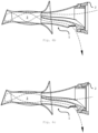
- Fig. 1a is a perspective view of this embodiment of the attachment 1 according to the invention without the ear funnel, which is optional in this embodiment.
- the attachment 1 comprises the connecting piece 4 for connecting the attachment 1 to a device 2 for generating an air flow, preferably a warm air flow, or for dispensing a fluid.
- the connecting piece 4 forms the section of the attachment 1 that ensures that the attachment 1 is held to the device 2.
- the attachment 1 comprises the tongue-like guide vane 5, which can be inserted into an external auditory canal 3 of an animal or human (hereinafter referred to as the user) for the purpose of drying the auditory canal 3 (see Fig. 6 ).
- the guide vane 5 enables a controlled guidance of the air flow and its controlled delivery to the external auditory canal 3.
- the guide vane 5 has a guide vane base 25 for guiding the air flow and can also comprise guide vane cheeks 26 in order to form a guide channel or part of a guide channel for the air flow.
- the essentially sleeve-shaped connecting piece 4 serves to connect the attachment 1 to the device 2 and allows the air flow from the device 2 to flow into the attachment 1.
- the geometry of the connecting piece 4 is based on the geometry of an outlet opening 15 of the device 2, through which outlet opening 15 the air flow flows out of the device 2.
- the tongue-shaped guide vane 5 protrudes from the connecting piece 4 in the illustrated embodiment and directs the air flow into the external auditory canal 3 of the user (see Fig. 6 ).
- Fig. 3a In order to be able to use the attachment 1 shown as intended for drying the external auditory canal 3, it can be inserted with the guide vane 5 - either in sections or completely - into the external auditory canal 3 of the user.
- the guide vane 5 is arranged such that the guide vane base 25 intersects the longitudinal axis 12 of the attachment 1.
- the longitudinal axis 12 of the attachment 1 runs through a center point of a normal to the Fig. 3a and 3b shown longitudinal section of the connecting piece 4.
- the cross section of the connecting piece 4 refers exclusively to the connecting piece 4 itself - in particular not to any sections of the guide vane 5 arranged within the connecting piece 4.
- the cross section of the connecting piece 4, through whose center the longitudinal axis 12 extends, is in Fig. 4c to see.
- This arrangement of the guide vane 5 directs the airflow into the user's external auditory canal 3 in such a way that a flow field is created in the external auditory canal 3 that is particularly advantageous for the desired drying effect. Furthermore, this ensures that the airflow exiting the attachment 1 is not directed directly onto the user's eardrum 31.
- the guide vane base 25 intersects the longitudinal axis 12 in a proximal end region of the attachment 1—that is, the end region closest to the user's eardrum 31.
- the guide vane base 25 has a curved longitudinal section which is normal to the Figures 4a and 4b
- the guide vane base 25 of a first section 5a of the guide vane 5 protruding from the connecting piece 4 has a longitudinal cross-sectional profile that is curved in a first direction
- the guide vane base 25 of a second section 5b of the guide vane 5 protruding from the connecting piece 4 has a longitudinal cross-sectional profile that is curved in a second direction, wherein the two curved sections 5a, 5b are curved in opposite directions.
- the second section 5b has a proximal end 7 of the guide vane 5.
- the guide vane 5 has at least a first vertex 13 and a second vertex 14.
- This special course of the guide vane 5 achieves a particularly favorable flow distribution of the air stream within the external auditory canal 3.
- particularly good drying results were achieved, especially in comparison with attachments comprising a guide vane 5 with a straight longitudinal cross-section. It is particularly advantageous if - viewed from the connecting piece 4 - the The gradient of a tangent applied to the guide vane base 25 decreases with the distance from the connecting piece 4 in the first section 5a of the guide vane base 25 and increases with the distance from the connecting piece 4 in the second section 5b of the guide vane base 25.
- the guide vane 5 has a section 5c running in the connecting piece 4, wherein the section 5c has a distal end 6 of the guide vane 5.
- the section 5c adjoins the section 5a of the guide vane 5.
- a flow cross-section for air flowing from the device 2 into the attachment 1 is limited by the section 5c of the guide vane 5 running in the connecting piece 4 and the connecting piece 4. This allows the portion of the total air flow to be adjusted which is to pass unhindered from the connecting piece 4 to the guide vane 5.
- the air flow can also be subjected to a flow cross-section constriction, which flow cross-section constriction can be less drastic in attachments for children, for example, than in attachments for adults.
- the section 5c of the guide vane 5 running in the connecting piece 4 also makes it possible to receive the air flow flowing from the device 2 into the attachment 1 already in the area of the connecting piece 4, so that the air flow can be directed accordingly immediately upon entry into the attachment 1.
- Two guide vane cheeks namely a first guide vane cheek 26 and a second guide vane cheek 27, protrude from the guide vane bottom 25 from the longitudinal edges 16 of the guide vane bottom 25 in order to form, together with the guide vane bottom 25, a guide channel 10 or part of a guide channel 10 for the air flow.
- the guide vane bottom 25 and the guide vane cheeks 26, 27 form part of the guide channel 10 if the guide vane cheeks 26, 27 protrude from the guide vane bottom 25 only in a longitudinal section of the guide vane 5, but not over its entire length.
- the guide channel 10 for the air flow formed by the guide vane base 25 and the guide vane cheeks 26, 27 is formed by the volume formed by the guide vane base 25, the first guide vane cheek 26 on the one hand, and the second guide vane cheek 27 on the other hand. is limited.
- the guide channel 10 can further improve the targeted and controlled guidance of the air flow within the attachment 1 as well as the controlled delivery of the air flow to the external auditory canal 3.
- ear funnels such as the first embodiment of the attachment 1 with ear funnel 18 according to Fig. 3b - by using the guide vane cheeks 26,27, any unwanted reflections of the air flow on an inner wall of the ear funnel 18 are avoided.
- Fig. 4a shows the cross section of the attachment 1 according to the invention according to section line AA from Fig. 3b .
- Fig. 4b shows the cross section according to section line BB from Fig. 3b In both cases, the cut runs through the ear funnel 18 and through the guide vane base 25 of the guide vane 5.
- Fig. 4c shows the cross section of the connecting piece 4 according to section line CC from Fig. 3b .
- the guide vane base 25 in the illustrated embodiment has a preferably U-shaped, curved cross-sectional profile.
- the cross section of the guide vane base 25 is curved over the entire length of the guide vane 5, slightly U-shaped.
- the curvature can increase or decrease from one end of the guide vane 5 to the other end of the guide vane 5.
- the cross section of the guide vane base 25 is not curved over the entire length of the guide vane 5, but only in a longitudinal section of the guide vane 5. Curvatures of the cross-sectional profile of the guide vane base 25 other than U-shaped are also conceivable.
- the attachment 1 according to the first embodiment can be inserted into the external auditory canal 3 either with or without ear funnel 18 to be used as intended for drying the external auditory canal 3.
- the perspectively shown ear funnel 18 gives the Fig. 2a, 2b and 3b illustrated attachment 1, namely the attachment 1 according to the first embodiment with ear funnel 18.
- the ear funnel 18 can be pushed onto the connecting piece 4 - or connected to it or the guide vane in some other way.
- the connecting piece 4 can be formed by an end section, preferably a distal end section - because it is located away from the user's eardrum 31 - of the ear funnel 18.
- the ear funnel 18 is detachably connectable to the connecting piece 4 and protrudes therefrom in such a way that the guide vane 5 is enclosed along its entire length by the ear funnel 18 and the adjoining connecting piece 4. It can also be provided that the ear funnel 18 and connecting piece 4 only enclose a longitudinal section of the guide vane 5, so that the guide vane 5 protrudes beyond the ear funnel 18.
- Fig. 1b In the present exemplary embodiment, the ear funnel 18 shown is rotationally symmetrical except for an outlet 24, wherein the longitudinal axis 12 of the attachment 1 forms the corresponding axis of rotation of the ear funnel 18.
- the proximal end 7 of the guide vane 5, or the proximal end 7a of the guide vane base 25, is arranged essentially flush with the proximal opening 19 of the ear funnel 18. Accordingly, the proximal end 7a of the guide vane base 25 is located within the proximal opening 19 of the ear funnel 18 and divides it into an outflow opening 22 for air flowing from the attachment into the external auditory canal 3, and an inflow opening 23, through which inflow opening 23 air can flow from the external auditory canal 3 back into the attachment 1.
- the guide vane 5 runs essentially over the entire length of the ear funnel 18.
- the air flow used for drying can be guided over the entire length of the ear funnel 18 and released into the external auditory canal in a very controlled manner without risking injury to the external auditory canal 3 and/or the eardrum.
- the outflow opening 22 can be smaller than the inflow opening 23.
- the outflow opening 22 can occupy one-third of the proximal opening 19 and the inflow opening 23 can occupy two-thirds of the proximal opening 19.
- proximal opening 19 of the ear funnel 18 is usually smaller than a distal opening 29 of the connecting piece 4
- drying by the air flow is further supported by increasing the exit velocity of the air flow from the attachment 1, ensuring a particularly rapid and complete escape of the moist air from the ear canal 3.
- the air flow from the device 2 flows into the attachment 1 via the distal opening of the connecting piece 4.
- an internal volume of the ear funnel 18 is defined by the guide vane base 25, and optionally the first guide vane cheek 26 and the second guide vane cheek 27, into an air supply duct 20 and an air exhaust duct 21.
- the longitudinal edges 16 of the guide vane base 25 or - if present - the adjoining guide vane cheeks 26, 27 can directly contact the ear funnel 18 either along their entire length or only in sections, or can be slightly spaced from the ear funnel 18.
- fluidic isolation can be achieved between the air supply duct 20 and the air exhaust duct 21.
- the supply air duct 20 connects the distal opening 29 of the connecting piece 4 with the outlet opening 22.
- the exhaust air duct 21 connects the inlet opening 23 of the ear funnel 18 with the outlet 24 of the attachment 1, which is formed as a recess in the housing on the underside of the ear funnel 18. Accordingly, the supply air duct 20 allows the air or fluid flow generated by the device 2 to flow into the user's external auditory canal 3, and the exhaust air duct 21 allows the air used to dry the external auditory canal 3 or the fluid used for cleaning or treatment to flow back out of the external auditory canal 3 into the atmosphere.
- the ear funnel 18 is rigid in comparison to the connecting piece 4 and/or the guide vane 5, preferably less flexible than the connecting piece 4 and/or the tongue 5.
- the ear funnel 18 protects, in particular, the guide vane 5 from any possible deformation.
- the ear funnel 18 can be made of polyethylene or polypropylene.
- connecting piece 4 and guide vane 5 can be made of thermoplastic elastomer or silicone.
- Fig. 3a shows the attachment 1 in a connection position in which the attachment 1 is connected to the device 2 (see also Fig. 5a, 5b and 5c ) is connected.
- the attachment 1 with the connecting piece 4 is inserted in sections into the outlet opening 15 for the air flow of the device 2.
- a locking projection 17 on a device-side end section of the connecting piece 4 engages with a retaining section 34 of the device 2 and thus prevents an unintentional release of the connection between the device 2 and the attachment 1 (see, for example, Fig. 6a or 9b .
- the air or fluid stream exiting the device 2 thus first flows through the connecting piece 4 of the attachment 1 when it flows into the attachment 1. This is also the case if the connecting piece 4 is not inserted into the outlet opening 15 but is connected to the device 2 in another way, for example, pushed onto it.
- a spacer 28 arranged circumferentially around the circumference of the connecting piece 4, at least in sections, is located on a housing of the device 2 and thus ensures that the connecting piece 4 cannot be inserted deeper than intended into the outlet opening 15.
- the ear funnel 18 can be pushed onto the connecting piece 4 for the purpose of connection and rest against the spacer 28.
- the connecting piece 4 and ear funnel 18 are connected to each other by frictional engagement, although other connection options are also possible - for example, by means of interlocking locking grooves and locking projections.
- Fig. 5a shows an ear drying device according to the invention, comprising the device 2 for generating an air flow and the attachment 1 according to the invention according to the first embodiment of the attachment according to the invention, wherein the ear funnel 18 has been removed from the one-piece unit consisting of connecting piece 4 and guide vane 5 and is therefore not visible.
- the device 2 is preferably designed specifically for the purpose of ear drying and can preferably be designed to be portable.
- Fig. 5b shows the ear drying device according to the invention comprising the device 2 for generating an air flow and the attachment 1 according to the invention with ear funnel 18.
- Fig. 5c shows the ear drying device according to the invention Fig. 5a or 5b .
- the attachment 1 is covered by a protective cap 30, which serves in particular to protect the attachment 1 during transport of the device 2.
- Fig. 6a is a schematic representation of the flow pattern of a device according to the invention caused by the attachment 1 in its operating state.
- the flow pattern depicted inside the external auditory canal 3 arises equally regardless of the specific embodiment of the attachment 1 according to the invention. Due to the comparatively high insertion depth of the attachment 1 into the external auditory canal 3, there is no reflection of the air flow exiting the attachment 1 on the side walls 8, 9; the air flow is swirled due to the guide vane 5 upon leaving the attachment 1, so that a vortex field favorable for drying is created inside the external auditory canal 3.
- Fig. 6b also shows the attachment 1 inserted into the ear canal 3, but with a lower insertion depth than in Fig. 6a This results in a different flow pattern inside the external auditory canal 3, which, however, is independent of the selected design of the attachment 1.
- the air flow exiting the attachment 1 is reflected on the side walls 8, 9 of the external auditory canal 3, so that a vortex field favorable for drying is created inside the external auditory canal 3.
- Fig. 6c shows the attachment 1 inserted into the ear canal 3, whereby the ear drying device is operated with different operating parameters, which results in a different exit angle of the air flow from the attachment 1. This results in a different flow pattern inside the external ear canal 3, which in turn is independent of the selected design of the attachment 1. In this case too, the air flow exiting the attachment 1 is reflected on the side walls 8, 9 of the external ear canal 3, so that a vortex field favorable for drying is created inside the external ear canal 3.
- FIGS. 7a, 7b, 7c and 7c are line representations of the Figures 1a, 1b, 2a and 2b .
- Fig. 8a, 8b, 8c and 8d show a fourth embodiment of the attachment 1 according to the invention. All of the statements made above in connection with the first, second, and third embodiments also apply to the fourth embodiment shown here.
- the connecting piece 4 of the attachment of the fourth embodiment has a plurality of recesses 32.
- the recesses are arranged in the device-side end section of the connecting piece 4, which end section also forms the locking projection 17.
- the recesses 32 have an angular spacing of 45°; accordingly, a total of eight recesses 32 are arranged in the end section of the connecting piece 4.
- the locking projection 17 of the connecting piece 4 which engages with the retaining section 34 of the device 2, prevents the inadvertent detachment of the attachment 1 from the device 2; however, the attachment 1 can be rotated as desired relative to the device 2, so that - depending on the rotational position - different orientations of the guide vane 5 can be realized.
- at least one locking lug 33 is provided on the device 2, preferably in the region of the outlet opening 15 (see Fig. 9a and 9b ), which locking lug 33 can be engaged with one of the recesses 32.
- the recesses 32 thus indicate preferred rotational positions of the attachment 1 on the device 2.
- Fig. 10a shows the attachment 1 before being connected to the device 2 for delivering a fluid, such as air, water, or other therapeutic or care liquid.
- a fluid such as air, water, or other therapeutic or care liquid.
- the attachment 1 can be pushed into the outlet opening 15 with its device-side end section.
- the retaining section 34 of the device 2 prevents the attachment 1 from being accidentally released from the device 2.
- the locking lug 33 can engage in the respective recess 32 at certain rotational positions of the attachment 1 corresponding to the recesses 32 in order to fix the attachment 1 in the corresponding rotational position. By rotating the attachment 1 out of this rotational position, the attachment 1 can be brought into another rotational position in which the locking lug 33 can engage in a different recess 32.
- Fig. 11a and 11b show a fifth embodiment of the attachment 1 according to the invention. All of the statements made above in connection with the first, second, third, and fourth embodiments also apply to the fifth embodiment shown here. Furthermore, two inflow elements 35 are arranged on the guide vane base 25 of the guide vane 5 of the attachment 1.
- Fig. 12a, 12b , 13a, 13b and 13c show a sixth embodiment of the attachment 1 according to the invention. All of the statements made above in connection with the first, second, third, fourth, and fifth embodiments also apply to the sixth embodiment shown here. Furthermore, the guide vane base 25 of this embodiment is not symmetrical, as is the case with the other embodiments described above, but rather asymmetrical.
- the second section 5b of the guide vane 25, which is curved in the second direction can be rotated relative to the first section 5a of the guide vane 25, which is curved in the first direction, as shown.
Landscapes
- Health & Medical Sciences (AREA)
- Life Sciences & Earth Sciences (AREA)
- Animal Behavior & Ethology (AREA)
- Veterinary Medicine (AREA)
- Public Health (AREA)
- General Health & Medical Sciences (AREA)
- Engineering & Computer Science (AREA)
- Biomedical Technology (AREA)
- Heart & Thoracic Surgery (AREA)
- Physics & Mathematics (AREA)
- Vascular Medicine (AREA)
- Psychology (AREA)
- Biophysics (AREA)
- Acoustics & Sound (AREA)
- Anesthesiology (AREA)
- Hematology (AREA)
- Thermal Sciences (AREA)
- Otolaryngology (AREA)
- Dental Tools And Instruments Or Auxiliary Dental Instruments (AREA)
- Structures Of Non-Positive Displacement Pumps (AREA)
- Headphones And Earphones (AREA)
- Nozzles (AREA)
- Respiratory Apparatuses And Protective Means (AREA)
- Massaging Devices (AREA)
- Professional, Industrial, Or Sporting Protective Garments (AREA)
Description
Die vorliegende Erfindung betrifft einen Aufsatz für eine Vorrichtung zur Generierung eines Luftstromes, vorzugsweise eines Warmluftstromes, oder zur Abgabe eines Fluids, welcher Aufsatz dazu eingerichtet ist, zumindest abschnittsweise in einen äußeren Gehörgang eines menschlichen oder tierischen Ohres eingeführt zu werden, um Feuchtigkeitsansammlungen in dem äußeren Gehörgang zu trocknen.The present invention relates to an attachment for a device for generating an air flow, preferably a warm air flow, or for dispensing a fluid, which attachment is designed to be inserted at least partially into an external auditory canal of a human or animal ear in order to dry moisture accumulation in the external auditory canal.
Des Weiteren betrifft die Erfindung ein Ohrentrocknungsgerät umfassend eine Vorrichtung zur Generierung eines Luftstromes sowie den erfindungsgemäßen Aufsatz.Furthermore, the invention relates to an ear drying device comprising a device for generating an air flow and the attachment according to the invention.
Darüber hinaus betrifft die Erfindung ein Gerät zur pflegenden oder therapeutischen Behandlung des äußeren Gehörgangs eines menschlichen oder tierischen Ohres.Furthermore, the invention relates to a device for the care or therapeutic treatment of the external auditory canal of a human or animal ear.
Patienten, die unter chronisch feuchten Gehörgängen leiden - sei es auf Grund einer Radikalhöhle, einer Trommelfellperforation oder einer anderen Erkrankung des äußeren Gehörgangs - oder auch Träger von Hörgeräten sind häufig mit dem Problem der effizienten Entfernung von Feuchtigkeit aus dem äußeren Gehörgang des Ohres konfrontiert. Zudem kann Wasser in der Badewanne, unter der Dusche oder beim Schwimmen in den Gehörgang gelangen, was zu einem verminderten Hörvermögen führen kann. Auch können Bakterien, Keime und Schmutz so leichter in den äußeren Gehörgang gelangen und dort Entzündungen hervorrufen, was eine rasche Entfernung dieser Flüssigkeitsansammlungen erforderlich macht.Patients suffering from chronically moist ear canals—whether due to a rhinoplasty, a perforated eardrum, or another condition of the external auditory canal—as well as hearing aid wearers, are often faced with the problem of efficiently removing moisture from the external auditory canal. Furthermore, water can enter the ear canal in the bathtub, shower, or while swimming, which can lead to reduced hearing. Bacteria, germs, and dirt can also more easily enter the external auditory canal and cause inflammation, necessitating the rapid removal of these fluid accumulations.
Aus dem Stand der Technik sind jedoch keine Vorrichtungen bekannt, mit Hilfe derer eine solche Entfernung auf gefahrlose und effiziente Weise möglich ist. Beispielsweise ist es bekannt, einen Luftstrom in den Gehörgang einzuleiten, durch den der äußere Gehörgang getrocknet werden soll. Ein in den äußeren Gehörgang einführbarer Aufsatz für eine Vorrichtung zur Generierung eines Luftstromes ist aus
In analoger Weise kann es bei der Befreiung des äußeren Gehörgangs von Cerumen mittels eines Fluids zu Verletzungen des Trommelfells kommen, wenn das Fluid direkt auf das Trommelfell geleitet wird. Zugleich können Cerumen-Rückstände im äußeren Gehörgang verbleiben und die Reinigung des äußeren Gehörgangs somit nur unzufrieden stellend betrieben werden, wenn das Fluid nicht den gesamten äußeren Gehörgang erreichen kann. Vorrichtungen zur Reinigung des äußeren Gehörgangs sind beispielsweise aus
Auch im Rahmen der Abgabe eines Fluids in den äußeren Gehörgang zum Zwecke der Pflege bzw. therapeutischen Behandlung des äußeren Gehörgangs kann es zu Verletzungen des Trommelfells kommen, wenn das Fluid direkt auf das Trommelfell geleitet wird. Der pflegende bzw. therapeutische Effekt einer solchen Behandlung des äußeren Gehörgangs mittels eines Fluids kann zudem nicht sein Maximum erreichen, wenn das Fluid nicht den gesamten äußeren Gehörgang erreichen kann.Even when administering a fluid into the external auditory canal for the purpose of caring for or therapeutically treating the external auditory canal, injuries to the eardrum can occur if the fluid is directed directly onto the eardrum. Furthermore, the caring or therapeutic effect of such a treatment of the external auditory canal using a fluid cannot be maximized if the fluid cannot reach the entire external auditory canal.
Daher ist es eine Aufgabe der vorliegenden Erfindung, einen Aufsatz für eine Vorrichtung zur Generierung eines Luftstromes, vorzugsweise eines Warmluftstromes, bereitzustellen, welcher Aufsatz eine rasche und effiziente Entfernung von Feuchtigkeit aus dem äußeren Gehörgang eines Menschen oder eines Tieres mittels eines Luftstromes ermöglicht, ohne dabei das Trommelfell der Gefahr einer Beschädigung auszusetzen.Therefore, it is an object of the present invention to provide an attachment for a device for generating an air flow, preferably a warm air flow, which attachment enables rapid and efficient removal of moisture from the external auditory canal of a human or an animal by means of an air flow, without exposing the eardrum to the risk of damage.
Außerdem soll der bereitgestellte Aufsatz auf unkomplizierte Weise an verschiedene Gehörgänge anpassbar sein, einen einfachen Aufbau aufweisen und in der Herstellung kostengünstig sein.In addition, the provided attachment should be easily adaptable to different ear canals, have a simple structure and be cost-effective to manufacture.
Die Effizienz von Ohrentrocknungsgeräten, welche den erfindungsgemäßen Aufsatz umfassen, soll zudem deutlich erhöht werden. Das erfindungsgemäße Ohrentrocknungsgerät soll ein merkbares Trocknungsergebnis bereits nach einer Anwendungsdauer von 15 Sekunden liefern. Eine vollständige Trocknung soll durch eine Anwendungsdauer von etwa 30 Sekunden oder weniger erreicht werden können.The efficiency of ear drying devices incorporating the attachment according to the invention is also intended to be significantly increased. The ear drying device according to the invention is intended to provide a noticeable drying result after only 15 seconds of use. Complete drying is intended to be achieved with an application time of approximately 30 seconds or less.
Zudem ist es eine Aufgabe der vorliegenden Erfindung, einen Aufsatz für eine Vorrichtung zur Abgabe eines Fluids bereitzustellen, welcher Aufsatz eine rasche und effiziente Entfernung von Cerumen aus dem äußeren Gehörgang eines Menschen oder eines Tieres mittels eines Fluids ermöglicht, ohne dabei das Trommelfell der Gefahr einer Beschädigung auszusetzen.Furthermore, it is an object of the present invention to provide an attachment for a device for dispensing a fluid, which attachment enables rapid and efficient removal of cerumen from the external auditory canal of a human or an animal by means of a fluid, without exposing the eardrum to the risk of damage.
Schließlich ist es eine Aufgabe der vorliegenden Erfindung, einen Aufsatz für eine Vorrichtung zur Abgabe eines Fluids bereitzustellen, welcher Aufsatz eine rasche und effiziente pflegende oder therapeutische Behandlung des äußeren Gehörgang eines Menschen oder eines Tieres mittels eines Fluids ermöglicht, ohne dabei das Trommelfell der Gefahr einer Beschädigung auszusetzen.Finally, it is an object of the present invention to provide an attachment for a device for dispensing a fluid, which attachment enables rapid and efficient care or therapeutic treatment of the external auditory canal of a human or animal by means of a fluid, without exposing the eardrum to the risk of damage.
Eine der Erfindung zugrunde liegende Aufgabe wird erfindungsgemäß durch einen Aufsatz für eine Vorrichtung zur Erzeugung eines Luftstromes, vorzugsweise eines Warmluftstromes, oder zur Abgabe eines Fluids gelöst, welcher Aufsatz dazu eingerichtet ist, zumindest abschnittsweise in einen äußeren Gehörgang eines menschlichen oder tierischen Ohres eingeführt zu werden, wobei der Aufsatz einen Verbindungsstutzen zur Anbindung an die Vorrichtung aufweist, wobei der Aufsatz eine von dem Verbindungsstutzen abstehende, zungenartig ausgebildete Leitschaufel zur Führung von aus der Vorrichtung ausströmender Luft oder von der Vorrichtung abgegebenem Fluid, mit einem Leitschaufelboden aufweist, und wobei die Leitschaufel dem Verbindungsstutzen in Strömungsrichtung des Luftstromes oder Fluids nachgeordnet ist, wobei, bei Betrachtung eines Längsquerschnitts des Aufsatzes, der Leitschaufelboden eine Längsachse des Aufsatzes schneidet, welche Längsachse durch den Mittelpunkt eines auf den Längsquerschnitt normal stehenden Querschnittes des Verbindungsstutzens verläuft, und wobei zumindest ein Anströmelement vorgesehen ist, welches Anströmelement von dem Leitschaufelboden abragt, um die aus der Vorrichtung ausströmende Luft oder das aus der Vorrichtung ausströmende Fluid zu verwirbeln. Der Verbindungsstutzen kann dabei unterschiedlich ausgestaltet sein. Er kann beispielsweise ein wesentliches Element des Aufsatzes ausbilden und diesem Stabilität verleihen. Er kann aber auch lediglich einen Abschnitt des Aufsatzes ausmachen, der die Anbindung des Aufsatzes an die Vorrichtung ermöglicht ohne dabei wesentlich zur Stabilität des Aufsatzes beizutragen.One object underlying the invention is achieved according to the invention by an attachment for a device for generating an air flow, preferably a warm air flow, or for delivering a fluid, which attachment is designed to be inserted at least partially into an external auditory canal of a human or animal ear, wherein the attachment has a connecting piece for connection to the device, wherein the attachment has a tongue-shaped guide vane projecting from the connecting piece for guiding air flowing out of the device or fluid delivered by the device, with a guide vane base, and wherein the guide vane is arranged downstream of the connecting piece in the flow direction of the air flow or fluid, wherein, when viewing a longitudinal cross-section of the attachment, the guide vane base intersects a longitudinal axis of the attachment, which longitudinal axis runs through the center of a cross-section of the connecting piece that is normal to the longitudinal cross-section, and wherein at least one inflow element is provided, which inflow element projects from the guide vane base in order to guide the air flowing out of the device or the fluid to swirl the fluid flowing out of the device. The connecting piece can be designed in different ways. For example, it can form an essential element of the attachment and provide stability. However, it can also simply constitute a section of the attachment that enables the attachment to be connected to the device without significantly contributing to the attachment's stability.
Die zungenartig ausgebildete Leitschaufel des Aufsatzes schneidet die durch den Mittelpunkt des Querschnittes des Verbindungsstutzens verlaufende Längsachse. Erfindungsgemäß setzt dies voraus, dass die Leitschaufel in einer Seitenansicht des Aufsatzes zumindest abschnittsweise schräg zu dieser Längsachse verläuft. Vorzugsweise kann die Leitschaufel über ihre Länge in Strömungsrichtung gesehen eine nicht verschwindende Steigung aufweisen. Erfindungsgemäß wird der Luftstrom oder Fluidstrom, welchen die Vorrichtung bereitstellt (im Folgenden wird der Einfachheit nur der Luftstrom genannt), über den erfindungsgemäßen Aufsatz in den äußeren Gehörgang eingeleitet und dabei durch die Leitschaufel so gelenkt, dass sich innerhalb des äußeren Gehörgangs eine für die erwünschte Trocknung besonders vorteilhafte Strömung einstellt. Der Luftstrom strömt dabei über den Verbindungsstutzen in den Aufsatz ein, durchströmt zunächst den Verbindungsstutzen und wird in weiterer Folge über den Leitschaufelboden der Leitschaufel in Richtung des äußeren Gehörgangs geführt. Dadurch, dass die Leitschaufel, insbesondere der Längsquerschnitt des Leitschaufelbodens, die Längsachse des Aufsatzes quer schneidet, wird der Luftstrom so gelenkt, dass er nicht direkt auf das Trommelfell des Anwenders auftrifft. Somit wird der Luftstrom durch den erfindungsgemäßen Aufsatz derart gelenkt, dass sich im Inneren des äußeren Gehörgangs näherungsweise ein Wirbelfeld ausbildet. Dieses Wirbelfeld kann sich - je nachdem, wie weit der Aufsatz in den äußeren Gehörgang des Anwenders eingeführt wird - entweder aufgrund eines Dralls ergeben, welchen der Luftstrom aufgrund der Leitschaufel erfährt, und/oder aufgrund von Reflexion des Luftstromes an zum Trommelfell führenden Seitenwänden des äußeren Gehörgangs ausbilden. Der Luftstrom kann dadurch nicht direkt auf das Trommelfell auftreffen, sondern nur auf die Seitenwände des äußeren Gehörgangs und an diesen Seitenwänden, vorzugsweise mehrmals, reflektiert werden, bevor er entlang des Trommelfells geleitet wird, so dass er an dessen Oberfläche entlang streicht. Beispielsweise kann der Luftstrom an einer oberen Seitenwand des Gehörgangs auftreffen, dort reflektiert werden und entlang des Trommelfells in Richtung einer unteren Seitenwand des äußeren Gehörgangs geleitet werden, wo der Luftstrom ein weiteres Mal reflektiert und schließlich in Richtung der Ohrmuschel gefördert wird. Es ist auch möglich, dass der Luftstrom mehrfach an den Seitenwänden des äußeren Gehörgangs reflektiert wird, bevor der Luftstrom das Trommelfell erreicht. Insbesondere können mittels des erfindungsgemäßen Aufsatzes Feuchtigkeitsansammlungen auch aus dem Recessus meatus acustici externi entfernt werden - also jener Mulde, welche sich unmittelbar vor dem Trommelfell zwischen dem schräg nach unten auf das Trommelfell zulaufenden Boden des äußeren Gehörgangs und dem diesen Boden überdachenden, schrägstehenden Trommelfell ergibt. Die Verwirbelung des Luftstromes, sei sie nun durch die Drallgebung und/oder durch Reflexion an den zum Trommelfell führenden Seitenwänden des äußeren Gehörgangs, führt dazu, dass der Luftstrom über das Trommelfell und den Recessus meatus acustici externi streicht, nicht aber frontal auf das Trommelfell auftrifft. Aufgrund des durch den erfindungsgemäßen Aufsatz bedingten Strömungsverlaufes des Luftstromes im Inneren des äußeren Gehörgangs kommt es zu besonders kurzen Anwendungszeiten, die für eine zufriedenstellende Trocknung erforderlich sind. Beispielsweise kann ein merkbarer Trocknungseffekt bereits nach 15 Sekunden verzeichnet werden, wenn ein erfindungsgemäßes Ohrtrocknungsgerät - wie es weiter unten beschrieben ist - mit dem erfindungsgemäßen Aufsatz zur Anwendung kommt. Um den äußeren Gehörgang vollständig zu trocknen - also den Feuchtegehalt im Gehörgang wieder auf das übliche Maß zu reduzieren, ist eine Anwendungsdauer von etwa 30 Sekunden oder weniger ausreichend.The tongue-shaped guide vane of the attachment intersects the longitudinal axis running through the center of the cross-section of the connecting piece. According to the invention, this requires that the guide vane, in a side view of the attachment, runs at least partially obliquely to this longitudinal axis. Preferably, the guide vane can have a non-zero gradient over its length in the direction of flow. According to the invention, the air flow or fluid flow provided by the device (hereinafter referred to simply as the air flow) is introduced into the external auditory canal via the attachment according to the invention and is guided by the guide vane in such a way that a particularly suitable drying area for the desired drying is created within the external auditory canal. advantageous flow is established. The air flow flows into the attachment via the connecting piece, initially flows through the connecting piece and is then guided via the guide vane base of the guide vane in the direction of the external auditory canal. Because the guide vane, in particular the longitudinal cross section of the guide vane base, intersects the longitudinal axis of the attachment transversely, the air flow is directed in such a way that it does not directly impact the user's eardrum. The air flow is thus directed by the attachment according to the invention in such a way that a vortex field is approximately formed inside the external auditory canal. This vortex field can - depending on how far the attachment is inserted into the user's external auditory canal - result either from a swirl which the air flow experiences due to the guide vane and/or from reflection of the air flow on the side walls of the external auditory canal leading to the eardrum. The airflow cannot therefore hit the eardrum directly, but only the side walls of the external auditory canal and be reflected by these side walls, preferably several times, before being directed along the eardrum, thus passing along its surface. For example, the airflow can hit an upper side wall of the eardrum, be reflected there, and be directed along the eardrum towards a lower side wall of the external auditory canal, where the airflow is reflected once more and finally directed towards the auricle. It is also possible for the airflow to be reflected several times by the side walls of the external auditory canal before reaching the eardrum. In particular, the attachment according to the invention can also be used to remove moisture accumulation from the external auditory meatus recess – that is, the depression that forms immediately in front of the eardrum between the floor of the external auditory canal, which slopes downwards towards the eardrum, and the slanted eardrum that covers this floor. The turbulence of the air stream, whether caused by swirling and/or reflection from the side walls of the external auditory canal leading to the eardrum, causes the air stream to sweep over the eardrum and the external auditory meatus recess, but not to hit the eardrum head-on. Due to the effect of the inventive attachment, The airflow pattern inside the external auditory canal results in particularly short application times, which are necessary for satisfactory drying. For example, a noticeable drying effect can be achieved after just 15 seconds when an ear-drying device according to the invention—as described below—is used with the attachment according to the invention. To completely dry the external auditory canal—that is, to reduce the moisture content in the auditory canal back to the normal level—an application time of approximately 30 seconds or less is sufficient.
Außerdem hat sich gezeigt, dass der erfindungsgemäße Aufsatz auch eine besonders schonende und zugleich effektive Entfernung von Cerumen aus dem äußeren Gehörgang ermöglicht, wenn der Aufsatz in Verbindung mit einer Vorrichtung zur Abgabe eines Fluids verwendet wird. Auf Grund der erfindungsgemäßen Leitschaufel bildet das Fluid, beispielsweise Wasser, im Inneren des äußeren Gehörgangs einen für die Reinigung besonders günstigen Strömungsverlauf aus. Analog zu dem oben beschriebenen Luftstrom wird auch das Fluid in ein näherungsweises Wirbelfeld gezwungen, wenn es in den äußeren Gehörgang einströmt, sodass einerseits ein direktes Auftreffen des Fluids auf das Trommelfell unterbunden wird und gleichzeitig durch die Verwirbelung und/oder Reflexion des Fluids an den Seitenwänden des äußeren Gehörgangs eine besonders effektive Entfernung von Cerumen aus dem äußeren Gehörgang, insbesondere von an den Seitenwänden ansitzendem Cerumen, sichergestellt ist.It has also been shown that the attachment according to the invention also enables particularly gentle and at the same time effective removal of cerumen from the external auditory canal when the attachment is used in conjunction with a device for dispensing a fluid. Due to the guide vane according to the invention, the fluid, for example water, forms a flow pattern inside the external auditory canal that is particularly favorable for cleaning. Analogous to the air flow described above, the fluid is also forced into an approximate vortex field when it flows into the external auditory canal, so that on the one hand a direct impact of the fluid on the eardrum is prevented and at the same time a particularly effective removal of cerumen from the external auditory canal, in particular cerumen adhering to the side walls, is ensured by the swirling and/or reflection of the fluid on the side walls of the external auditory canal.
Weiters hat sich herausgestellt, dass der erfindungsgemäße Aufsatz auch eine besonders schonende und zugleich effektive pflegende oder therapeutische Behandlung des äußeren Gehörgangs ermöglicht, wenn der Aufsatz in Verbindung mit einer Vorrichtung zur Abgabe eines Fluids verwendet wird. Auf Grund der erfindungsgemäßen Leitschaufel bildet das Fluid im Inneren des äußeren Gehörgangs einen für die pflegende oder therapeutische Behandlung des äußeren Gehörgangs besonders günstigen Strömungsverlauf aus. Dabei können Verletzungen des Trommelfells vermieden und eine Maximierung des pflegenden oder therapeutischen Effektes erzielt werden, da das zur pflegenden oder therapeutischen Behandlung verwendete Fluid nicht direkt auf das Trommelfell gelenkt wird und auf Grund der erfindungsgemäßen Verwirbelung und/oder Reflexion des Fluids die Seitenwände des äußeren Gehörgangs besonders gut erreichen kann.Furthermore, it has been found that the attachment according to the invention also enables a particularly gentle and at the same time effective care or therapeutic treatment of the external auditory canal when the attachment is used in conjunction with a device for dispensing a fluid. Due to the guide vane according to the invention, the fluid inside the external auditory canal forms a flow path that is particularly favorable for the care or therapeutic treatment of the external auditory canal. Injuries to the eardrum can be avoided and a maximization of the care or therapeutic effect can be achieved, since the fluid used for the care or therapeutic treatment is not directed directly onto the eardrum and due to the inventive Turbulence and/or reflection of the fluid can reach the side walls of the external auditory canal particularly well.
Während es zur Verwirklichung des oben beschriebenen, erfindungsgemäßen Effekts, der eine schonende Trocknung des Trommelfells ermöglicht, grundsätzlich ausreichend ist, die zungenartig ausgebildete Leitschaufel in den äußeren Gehörgang einzuführen und entweder die durch die Leitschaufel bewirkte Verwirbelung des Luftstroms oder die ebenfalls durch die Leitschaufel bewirkte Reflexion und/oder Verwirbelung an den Wänden des äußeren Gehörgangs ausnützt, kann es vorteilhaft sein, zusätzlich einen Ohrtrichter für den Aufsatz vorzusehen.While it is generally sufficient to achieve the above-described effect according to the invention, which enables gentle drying of the eardrum, to insert the tongue-like guide vane into the external auditory canal and to utilize either the turbulence of the air flow caused by the guide vane or the reflection and/or turbulence on the walls of the external auditory canal, which is also caused by the guide vane, it may be advantageous to additionally provide an ear funnel for the attachment.
Gemäß einer bevorzugten Ausführungsform des erfindungsgemäßen Aufsatzes ist es daher vorgesehen, dass der Aufsatz einen Ohrtrichter umfasst, welcher Ohrtrichter die zungenartig ausgebildete Leitschaufel zumindest abschnittsweise, vorzugsweise gänzlich, der Länge nach umhüllt und eine proximale Öffnung aufweist, mit welcher proximalen Öffnung der Aufsatz bei bestimmungsgemäßer Verwendung in den äußeren Gehörgang eingeführt oder angesetzt ist, sodass die proximale Öffnung die dem Trommelfell nächstgelegene Öffnung des Ohrtrichters darstellt, wobei der Ohrtrichter an den Verbindungsstutzen anschließt und von diesem absteht, oder der Verbindungsstutzen einen Endabschnitt des Ohrtrichters ausbildet.According to a preferred embodiment of the attachment according to the invention, it is therefore provided that the attachment comprises an ear funnel, which ear funnel encloses the tongue-like guide vane at least in sections, preferably completely, lengthwise and has a proximal opening, with which proximal opening the attachment is inserted or attached into the external auditory canal when used as intended, so that the proximal opening represents the opening of the ear funnel closest to the eardrum, wherein the ear funnel connects to the connecting piece and protrudes from it, or the connecting piece forms an end section of the ear funnel.
Der Ohrtrichter dient dabei als jener Teil des Aufsatzes, welcher in direkten Kontakt mit dem äußeren Gehörgang bzw. den Seitenwänden desselben gebracht wird, wenn der Aufsatz bestimmungsgemäß verwendet und in den äußeren Gehörgang des Anwenders eingeführt wird. Der Ohrtrichter kann an den Verbindungsstutzen des Aufsatzes anschließen und von diesem abstehen bzw. kann der Verbindungsstutzen einen Endabschnitt des Ohrtrichters ausbilden. Die Leitschaufel ist zumindest abschnittsweise innerhalb des, vorzugsweise hülsenförmigen, Ohrtrichters angeordnet. Vorzugsweise ragt die Leitschaufel nicht aus dem Ohrtrichter heraus. Der Ohrtrichter ermöglicht einerseits eine leichte Aufweitung und eine für die Trocknung vorteilhafte Positionierung - nämlich eine leichte Begradigung - des üblicherweise schräg verlaufenden äußeren Gehörgangs, wenn der Aufsatz mit dem Ohrtrichter in den äußeren Gehörgang eines Menschen oder eines Tieres eingeführt ist; andererseits erlaubt der Ohrtrichter aber auch eine einfache Anpassung des Aufsatzes an verschiedene Gegebenheiten, wie die Anwendung bei Erwachsenen oder Kindern - etwa durch entsprechende Wahl von Form und Größe des Ohrtrichters. Die Länge des Ohrtrichters kann auf den Längsverlauf der Leitschaufel abgestellt sein, um die Ausbildung der oben beschriebenen Verwirbelungen und Reflexionen im äußeren Gehörgang zu unterstützen.The ear funnel serves as the part of the attachment that comes into direct contact with the external auditory canal or its side walls when the attachment is used as intended and inserted into the user's external auditory canal. The ear funnel can be connected to the connecting piece of the attachment and protrude from it, or the connecting piece can form an end section of the ear funnel. The guide vane is arranged at least partially within the preferably sleeve-shaped ear funnel. Preferably, the guide vane does not protrude from the ear funnel. The ear funnel allows, on the one hand, a slight widening and a positioning advantageous for drying - namely, a slight straightening - of the usually slanted outer The ear canal, when the ear funnel attachment is inserted into the external auditory canal of a human or animal, is used. On the other hand, the ear funnel also allows for easy adaptation to different circumstances, such as use in adults or children, for example, by selecting the appropriate shape and size of the ear funnel. The length of the ear funnel can be adjusted to the longitudinal shape of the guide vane to support the formation of the turbulence and reflections in the external auditory canal described above.
Gemäß einer weiteren bevorzugten Ausführungsform des erfindungsgemäßen Aufsatzes ist es vorgesehen, dass, bei Betrachtung eines Längsquerschnitts des Aufsatzes, der Leitschaufelboden auch eine Längsachse des Ohrtrichters schneidet, welche Längsachse durch den Mittelpunkt der proximalen Öffnung des Ohrtrichters verläuft. Bei bestimmungsgemäßer Verwendung des Aufsatzes zur Trocknung des äußeren Gehörgangs ist der Aufsatz mit der proximalen Öffnung des Ohrtrichters in den äußeren Gehörgang des Anwenders eingeführt oder an diesen angesetzt. Der Begriff proximal bezieht sich dabei und im Folgenden auf die Lage eines bestimmten Elementes relativ zu dem Trommelfell des Anwenders. Konkret ist mit der proximalen Öffnung die dem Trommelfell des Anwenders nächstgelegene Öffnung des Ohrtrichters gemeint.According to a further preferred embodiment of the attachment according to the invention, it is provided that, when viewed in a longitudinal cross-section of the attachment, the guide vane base also intersects a longitudinal axis of the ear funnel, which longitudinal axis runs through the center of the proximal opening of the ear funnel. When the attachment is used as intended for drying the external auditory canal, the attachment is inserted into the user's external auditory canal with the proximal opening of the ear funnel or is attached to it. The term proximal refers here and below to the position of a specific element relative to the user's eardrum. Specifically, the proximal opening refers to the opening of the ear funnel closest to the user's eardrum.
Sofern der Ohrtrichter rotationssymmetrisch ist - was abgesehen von einer Auslassöffnung im Mantel des Ohrtrichters vorzugsweise der Fall ist - fällt die Längsachse des Ohrtrichters mit dessen Rotationsachse zusammen. Die Leitschaufel kann derart innerhalb des Ohrtrichters angeordnet sein, dass in einem Längsschnitt betrachtet, der Leitschaufelboden, die Längsachse des Ohrtrichters schneidet, wobei es sich als besonders effektiv für die zu erzielenden Verwirbelungen bzw. Reflexionen und damit für die zu erzielende Trocknung herausgestellt hat, wenn der Leitschaufelboden die Längsachse des Ohrtrichters in seinem proximalen Endbereich schneidet.If the ear funnel is rotationally symmetrical—which is preferably the case, except for an outlet opening in the ear funnel casing—the longitudinal axis of the ear funnel coincides with its axis of rotation. The guide vane can be arranged within the ear funnel such that, viewed in a longitudinal section, the guide vane base intersects the longitudinal axis of the ear funnel. It has proven particularly effective for the desired turbulence and reflections, and thus for the desired drying, if the guide vane base intersects the longitudinal axis of the ear funnel in its proximal end region.
Vorzugsweise fällt die Längsachse des Ohrtrichters mit der Längsachse des Aufsatzes zusammen.Preferably, the longitudinal axis of the ear funnel coincides with the longitudinal axis of the attachment.
Gemäß einer bevorzugten Ausführungsform des erfindungsgemäßen Aufsatzes ist es vorgesehen, dass der Leitschaufelboden eines ersten Abschnitts der Leitschaufel einen Längsquerschnittsverlauf aufweist, der in eine erste Richtung gekrümmt ist, und der Leitschaufelboden eines zweiten Abschnitts der Leitschaufel einen Längsquerschnittsverlauf aufweist, der in eine zweite Richtung gekrümmt ist, und die beiden gekrümmten Abschnitte (5a,5b) zu einander entgegengesetzt gekrümmt verlaufen.According to a preferred embodiment of the attachment according to the invention, it is provided that the guide vane base of a first section of the guide vane has a longitudinal cross-sectional profile which is curved in a first direction, and the guide vane base of a second section of the guide vane has a longitudinal cross-sectional profile which is curved in a second direction, and the two curved sections (5a, 5b) are curved in opposite directions to one another.
Durch diesen speziellen Verlauf der Leitschaufel bzw. des Leitschaufelbodens wird eine besonders günstige Strömungsverteilung des Luftstromes innerhalb des äußeren Gehörganges erzielt. Bei dieser Ausführungsform der Erfindung konnten besonders gute Ergebnisse bei der Trocknung erzielt werden, insbesondere im Vergleich mit Aufsätzen mit geradem Längsquerschnittsverlauf. Besonders vorteilhaft ist es, wenn - von dem Verbindungsstutzen aus betrachtet - die Steigung einer an den Leitschaufelboden angelegten Tangente im ersten Abschnitt des Leitschaufelbodens mit dem Abstand von dem Verbindungsstutzen abnimmt und im zweiten Abschnitt des Leitschaufelbodens mit dem Abstand von dem Verbindungsstutzen zunimmt.This special configuration of the guide vane or vane base results in a particularly favorable airflow distribution within the external auditory canal. This embodiment of the invention has achieved particularly good drying results, particularly compared to attachments with a straight longitudinal cross-section. It is particularly advantageous if—as viewed from the connecting piece—the gradient of a tangent to the guide vane base decreases with distance from the connecting piece in the first section of the guide vane base and increases with distance from the connecting piece in the second section of the guide vane base.
Gemäß einer weiteren bevorzugten Ausführungsform der Erfindung ist es vorgesehen, dass der erste Abschnitt und der zweite Abschnitt unmittelbar ineinander übergehen. Insbesondere ist es strömungstechnisch günstig, wenn der erste Abschnitt und der zweite Abschnitt des Leitschaufelbodens nicht durch eine Unstetigkeit voneinander getrennt sind sondern glatt ineinander übergehen.According to a further preferred embodiment of the invention, the first section and the second section merge directly into one another. In particular, it is advantageous from a flow perspective if the first section and the second section of the guide vane base are not separated by a discontinuity, but rather merge smoothly into one another.
Dies führt zu einem für die erwünschten Trocknungseffekte besonders günstigen Strömungsverlauf des zur Trocknung dienenden Luftstromes innerhalb des äußeren Gehörgangs.This leads to a flow pattern of the air stream used for drying within the external auditory canal that is particularly favorable for the desired drying effects.
Gemäß einer weiteren bevorzugten Ausführungsform des erfindungsgemäßen Aufsatzes ist es vorgesehen, dass die zungenartig ausgebildete Leitschaufel zwei von dem Leitschaufelboden abstehende Leitschaufelwangen, nämlich eine erste Leitschaufelwange und eine zweite Leitschaufelwange, aufweist, wobei Leitschaufelboden und Leitschaufelwangen einen Leitkanal oder einen Teil eines Leitkanals für die aus der Vorrichtung ausströmende Luft ausbilden.According to a further preferred embodiment of the attachment according to the invention, it is provided that the tongue-shaped guide vane has two guide vane cheeks projecting from the guide vane base, namely a first guide vane cheek and a second guide vane cheek, wherein the guide vane base and Guide vane cheeks form a guide channel or part of a guide channel for the air flowing out of the device.
Durch die Leitschaufelwangen kann eine gezielte und kontrollierte Führung des Luftstromes entlang der Leitschaufel sowie eine kontrollierte Abgabe des Luftstromes an den äußeren Gehörgang sichergestellt werden. Auch können, bei Ausführungsformen des Aufsatzes mit Ohrtrichter, etwaige ungewollte Reflexionen des Luftstromes an einer Innenwand des Ohrtrichters vermieden werden. Dabei können die Leitschaufelwangen den Ohrtrichter beispielsweise über die gesamte Länge des Leitschaufelbodens oder auch nur in einem oder mehreren Längsabschnitten des Leitschaufelbodens kontaktieren. Alternativ können die Leitschaufelwangen aber auch von dem Ohrtrichter beabstandet sein.The guide vane cheeks ensure targeted and controlled guidance of the airflow along the guide vane and controlled delivery of the airflow to the external auditory canal. In versions of the attachment with an ear funnel, any unwanted reflections of the airflow on the inner wall of the ear funnel can also be avoided. The guide vane cheeks can contact the ear funnel, for example, over the entire length of the guide vane base or only in one or more longitudinal sections of the guide vane base. Alternatively, the guide vane cheeks can also be spaced apart from the ear funnel.
Gemäß einer weiteren bevorzugten Ausführungsform ist es vorgesehen, dass die erste Leitschaufelwange von einem ersten längsseitigen Rand des Leitschaufelbodens absteht und die zweite Leitschaufelwange von einem dem ersten längsseitigen Rand gegenüberliegenden zweiten längsseitigen Rand des Leitschaufelbodens absteht. Alternativ kann es auch vorgesehen sein, dass die erste Leitschaufelwange durch den ersten längsseitigen Rand des Leitschaufelbodens und die zweite Leitschaufelwange durch den zweiten längsseitigen Rand des Leitschaufelbodens ausgebildet ist.According to a further preferred embodiment, the first guide vane cheek protrudes from a first longitudinal edge of the guide vane base, and the second guide vane cheek protrudes from a second longitudinal edge of the guide vane base opposite the first longitudinal edge. Alternatively, the first guide vane cheek may be formed by the first longitudinal edge of the guide vane base, and the second guide vane cheek may be formed by the second longitudinal edge of the guide vane base.
Dabei begrenzen die Leitschaufelwangen den Leitschaufelboden an dessen einander gegenüberliegenden Längsseiten und verhindern weitestgehend, dass der zur Trocknung dienende Luftstrom aus dem Leitkanal in andere Bereiche des Aufsatzes, beispielsweise in einen Abluftkanal, gelangen kann, bevor er zur bestimmungsgemäßen Trocknung in den äußeren Gehörgang gelangt. Wenn die Leitschaufelwangen hingegen über ihre gesamte Längserstreckung den Ohrtrichter kontaktieren, kann ein solches Überströmen von Luft aus dem Leitkanal in andere Bereiche, etwa den Abluftkanal, vollständig verhindert werden. So können Leitkanal und Abluftkanal durch die Leitschaufel fluidisch voneinander isoliert bzw. getrennt werden. Besonders vorteilhafte Trocknungseffekte lassen sich erzielen, wenn die Leitschaufelwangen über die gesamte Länge der Leitschaufel verlaufen. Die Leitschaufelwangen können auch einstückig mit dem Leitschaufelboden gefertigt sein und können durch den ersten längsseitigen Rand und den diesem gegenüberliegenden zweiten längsseitigen Rand des Leitschaufelbodens ausgebildet sein. Die Leitschaufelwangen können ein Querschnittsprofil mit im Vergleich zum zwischen den Leitschaufelwangen liegenden Leitschaufelboden unterschiedlicher Krümmung aufweisen. Der Übergang zwischen Leitschaufelboden und Leitschaufelwangen kann fließend sein und sich etwa lediglich durch eine Veränderung in der Steigung bzw. Krümmung des Querschnittsprofils des Leitschaufelbodens äußern. Dies kann eine eindeutige Unterscheidung zwischen Leitschaufelboden und Leitschaufelwangen erschweren. Beispielsweise können Leitschaufelboden und Leitschaufelwangen derart angeordnet sein, dass ein durch Leitschaufelboden und Leitschaufelwangen ausgebildeter Gesamtquerschnitt der Leitschaufel im Wesentlichen U-förmig ausgebildet ist.The guide vane cheeks limit the guide vane base on its opposite longitudinal sides and largely prevent the air flow from the guide channel, which is used for drying, from reaching other areas of the attachment, for example, an exhaust air duct, before it reaches the external auditory canal for its intended drying. If, however, the guide vane cheeks contact the ear funnel over their entire length, such an overflow of air from the guide channel into other areas, such as the exhaust air duct, can be completely prevented. In this way, the guide channel and exhaust air duct can be fluidically isolated or separated from one another by the guide vane. Particularly advantageous drying effects can be achieved if the guide vane cheeks run along the entire length of the guide vane. The guide vane cheeks can also be made integrally with the Guide vane base and can be formed by the first longitudinal edge and the second longitudinal edge of the guide vane base opposite it. The guide vane cheeks can have a cross-sectional profile with a different curvature than the guide vane base located between the guide vane cheeks. The transition between the guide vane base and the guide vane cheeks can be smooth and can be expressed, for example, only by a change in the gradient or curvature of the cross-sectional profile of the guide vane base. This can make it difficult to clearly distinguish between the guide vane base and the guide vane cheeks. For example, the guide vane base and the guide vane cheeks can be arranged such that an overall cross-section of the guide vane formed by the guide vane base and the guide vane cheeks is essentially U-shaped.
Gemäß einer weiteren bevorzugten Ausführungsform des erfindungsgemäßen Aufsatzes ist es vorgesehen, dass die zungenartig ausgebildete Leitschaufel einen im Verbindungsstutzen verlaufenden Abschnitt aufweist.According to a further preferred embodiment of the attachment according to the invention, it is provided that the tongue-shaped guide vane has a section running in the connecting piece.
Dies ist insbesondere dann von Vorteil, wenn der Aufsatz keinen oder einen abnehmbaren Ohrtrichter aufweist. Der Verbindungsstutzen dient in diesem Fall einerseits zur Anbindung an die Vorrichtung zur Erzeugung des Luftstroms, verleiht andererseits aber auch dem Aufsatz die erforderliche Stabilität, um die Leitschaufel zu tragen.This is particularly advantageous when the attachment has no ear funnel or a removable one. In this case, the connecting piece serves both as a connection to the airflow generation device and as a support for the guide vane.
Um Verletzungen des Trommelfells und/oder der Seitenwand des äußeren Gehörgangs zu vermeiden, ist es bei einer weiteren bevorzugten Ausführungsform des erfindungsgemäßen Aufsatzes vorgesehen, dass die zungenartig ausgebildete Leitschaufel vollständig innerhalb des Ohrtrichters und/oder des Verbindungsstutzens angeordnet ist.In order to avoid injuries to the eardrum and/or the side wall of the external auditory canal, a further preferred embodiment of the attachment according to the invention provides that the tongue-shaped guide vane is arranged completely within the ear funnel and/or the connecting piece.
Bei Aufsätzen gemäß dieser Ausführungsform der Erfindung kann die Gefahr von Verletzungen des Trommelfells und/oder der Seitenwände des äußeren Gehörgangs des Anwenders minimiert werden, da die gesamte Leitschaufel im Inneren des Aufsatzes verborgen ist. Insbesondere können erster und zweiter Abschnitt der Leitschaufel innerhalb des Ohrtrichters und der im Verbindungsstutzen verlaufende Abschnitt der Leitschaufel innerhalb des Verbindungsstutzens angeordnet sein.With attachments according to this embodiment of the invention, the risk of injury to the eardrum and/or the lateral walls of the external auditory canal of the user can be minimized, since the entire guide vane is concealed inside the attachment. In particular, the first and second sections of the guide vane can be concealed within the ear funnel and the connecting piece. Section of the guide vane must be arranged within the connecting piece.
Gemäß einer weiteren bevorzugten Ausführungsform des Aufsatzes gemäß dieser Erfindung ist es vorgesehen, dass sich der Ohrtrichter von dem Verbindungsstutzen hin zu einer proximalen Öffnung des Ohrtrichters verjüngt.According to a further preferred embodiment of the attachment according to this invention, it is provided that the ear funnel tapers from the connecting piece towards a proximal opening of the ear funnel.
Die proximale Öffnung hat vorzugsweise einen kreisrunden Umfang und einen Durchmesser von nicht mehr als 7 mm. Da somit die Form des Ohrtrichters zumindest in einem proximalen Abschnitt des Ohrtrichters, welcher in den Gehörgang eingeführt wird, an die Form des äußeren Gehörgangs angepasst ist, ermöglicht dies ein besonders einfaches und schmerzfreies Einführen des Aufsatzes in den äußeren Gehörgang. Der erfindungsgemäße Aufsatz kann somit bis auf etwa 15 mm, vorzugsweise 10 mm, weit an das Trommelfell des Anwenders herangeführt werden, wodurch die Ausbildung des weiter oben beschriebenen näherungsweisen Wirbelfeldes im äußeren Gehörgang unterstützt und eine Trocknung von Flüssigkeitsansammlungen im Recessus meatus acustici externi begünstigt werden kann. Die erzielbare minimale Entfernung vom Trommelfell kann je nach spezieller Eignung des Aufsatzes für die Verwendung an Männern, Frauen oder Kindern variieren.The proximal opening preferably has a circular circumference and a diameter of no more than 7 mm. Since the shape of the ear funnel is adapted to the shape of the external auditory canal, at least in a proximal section of the ear funnel, which is inserted into the auditory canal, this enables particularly simple and painless insertion of the attachment into the external auditory canal. The attachment according to the invention can thus be brought up to approximately 15 mm, preferably 10 mm, close to the user's eardrum, which supports the formation of the approximate vortex field described above in the external auditory canal and can promote the drying of fluid accumulations in the external auditory meatus recess. The achievable minimum distance from the eardrum can vary depending on the specific suitability of the attachment for use on men, women, or children.
Besonders bevorzugt ist ein proximales, dem Trommelfell nächstgelegenes Ende der Leitschaufel, vorzugsweise ein proximales Ende des Leitschaufelbodens, im Inneren der proximalen Öffnung des Ohrtrichters angeordnet.Particularly preferably, a proximal end of the guide vane closest to the eardrum, preferably a proximal end of the guide vane base, is arranged inside the proximal opening of the ear funnel.
Bei solchen Ausführungsformen der Erfindung schließt die Leitschaufel im Wesentlichen bündig mit dem Ohrtrichter ab. Dadurch kann der Luftstrom beim Austritt aus dem Aufsatz über die proximale Öffnung des Ohrtrichters in den äußeren Gehörgang besonders gut gelenkt werden. Sowohl ein Austrittswinkel, unter welchem der Luftstrom - bezogen auf die Längsachse des Ohrtrichters oder des Aufsatzes - aus dem Aufsatz ausströmt, als auch ein Drall, welcher dem Luftstrom bei Austritt aus dem Aufsatz mitgegeben werden soll, lassen sich bei dieser Ausführungsform besonders gut einstellen. Insbesondere kann so ein Einfallswinkel, unter welchem der Luftstrom auf die Seitenwände des äußeren Gehörgangs auftrifft, noch besser vorbestimmt werden.In such embodiments of the invention, the guide vane is essentially flush with the ear funnel. This allows the air flow to be directed particularly well as it exits the attachment via the proximal opening of the ear funnel into the external auditory canal. Both the exit angle at which the air flow exits the attachment - relative to the longitudinal axis of the ear funnel or the attachment - and the swirl that is to be imparted to the air flow as it exits the attachment can be adjusted particularly well in this embodiment. In particular, the angle of incidence at which the air flow impacts the lateral walls of the external auditory canal can be better determined.
Gemäß einer weiteren bevorzugten Ausführungsform des erfindungsgemäßen Aufsatzes ist es vorgesehen, dass das proximale Ende der Leitschaufel, vorzugsweise ein proximales Ende des Leitschaufelbodens, die proximale Öffnung des Ohrtrichters in eine Ausströmöffnung für aus dem Aufsatz in den Gehörgang ausströmende Luft sowie eine Einströmöffnung für aus dem Gehörgang in den Aufsatz einströmende Luft unterteilt.According to a further preferred embodiment of the attachment according to the invention, it is provided that the proximal end of the guide vane, preferably a proximal end of the guide vane base, divides the proximal opening of the ear funnel into an outflow opening for air flowing out of the attachment into the auditory canal and an inflow opening for air flowing into the attachment from the auditory canal.
Über die proximale Öffnung des Ohrtrichters strömt also einerseits der zur Trocknung dienende, trockene Luftstrom, vorzugsweise Warmluftstrom, aus dem Aufsatz in den äußeren Gehörgang ein - nämlich im Bereich der Ausströmöffnung; andererseits kann feuchte Luft aus dem äußeren Gehörgang über die proximale Öffnung aber auch wieder in den Aufsatz einströmen - nämlich im Bereich der Einströmöffnung. Somit ermöglicht der Ohrtrichter auch das Ausströmen der zur Trocknung verwendeten Luft aus dem Gehörgang und unterbindet die Entstehung eines Strömungsrückstaus innerhalb des Gehörgangs. Feuchte Luft kann den äußeren Gehörgang somit unmittelbar nach der Aufnahme von Feuchtigkeit und isoliert von den Seitenwänden des äußeren Gehörgangs wieder verlassen, was zu einem verbesserten Trocknungseffekt führt. Somit kann sichergestellt werden, dass der zur Trocknung verwendete Luftstrom im Bereich der proximalen Öffnung nicht mit feuchter Luft vermischt wird, bevor er in den äußeren Gehörgang eingeleitet wird. Das proximale Ende der Leitschaufel bzw. das proximale Ende des Leitschaufelbodens und/oder die Leitschaufelwangen kontaktieren in diesem Fall eine Innenseite des Ohrtrichters, um die Einströmöffnung und die Ausströmöffnung fluidisch voneinander zu trennen.On the one hand, the dry air stream, preferably warm air, used for drying purposes flows from the attachment into the external auditory canal via the proximal opening of the ear speculum – namely in the area of the outflow opening. On the other hand, moist air from the external auditory canal can flow back into the attachment via the proximal opening – namely in the area of the inflow opening. The ear speculum thus also allows the air used for drying to flow out of the ear canal and prevents the formation of a backflow within the ear canal. Moist air can therefore leave the external auditory canal immediately after absorbing moisture and isolated from the side walls of the external auditory canal, leading to an improved drying effect. This ensures that the air stream used for drying is not mixed with moist air in the area of the proximal opening before it is introduced into the external auditory canal. In this case, the proximal end of the guide vane or the proximal end of the guide vane base and/or the guide vane cheeks contact an inner side of the ear funnel in order to fluidically separate the inflow opening and the outflow opening.
Gemäß einer weiteren bevorzugten Ausführungsform der Erfindung ist es vorgesehen, dass die zungenartig ausgebildete Leitschaufel ein Innenvolumen des Ohrtrichters in einen Zuluftkanal für aus dem Aufsatz in den Gehörgang strömende Luft sowie einen Abluftkanal für aus dem Gehörgang in den Aufsatz strömende Luft unterteilt, wobei vorzugsweise der Zuluftkanal den Verbindungsstutzen mit der Ausströmöffnung verbindet und wobei vorzugsweise der Abluftkanal die Einströmöffnung mit einem Auslass des Aufsatzes verbindet.According to a further preferred embodiment of the invention, it is provided that the tongue-like guide vane divides an inner volume of the ear funnel into an air supply channel for air flowing from the attachment into the auditory canal and an exhaust air channel for air flowing from the auditory canal into the attachment, wherein preferably the air supply channel connects the connecting piece with the Outlet opening and wherein preferably the exhaust air duct connects the inlet opening with an outlet of the attachment.
Hierdurch können der trockene Luftstrom und die feuchte aus dem äußeren Gehörgang austretende Luft im Aufsatz weitestgehend separat voneinander geführt werden. Der trockene Luftstrom, vorzugsweise Warmluftstrom, wird dabei zunächst durch die Vorrichtung erzeugt, durch den Verbindungsstutzen und über die Leitschaufel über den Zuluftkanal des Ohrtrichters geführt und in den äußeren Gehörgang geleitet. Nach der Trocknung des äußeren Gehörgangs, insbesondere des Recessus meatus acustici externi, kann die feuchte Luft den äußeren Gehörgang über die Einströmöffnung verlassen und wird über den Abluftkanal zu dem Auslass des Ohrtrichters geführt, über welchen Auslass die feuchte Luft aus dem Aufsatz ausgestoßen wird. Innerhalb des Aufsatzes kommt es somit zu keiner oder nur in einem sehr geringen Maße zu einer Vermischung der im Zuluftkanal und im Abluftkanal geführten Luftmassen, was die Effizienz der Trocknung weiter erhöht.This allows the dry air stream and the moist air escaping from the external auditory canal to be guided largely separately from one another within the attachment. The dry air stream, preferably warm air, is first generated by the device, then guided through the connecting piece and over the guide vane via the supply air duct of the ear speculum and then into the external auditory canal. After the external auditory canal, in particular the external acoustic meatus recess, has been dried, the moist air can leave the external auditory canal through the inlet opening and is guided via the exhaust air duct to the outlet of the ear speculum, through which the moist air is expelled from the attachment. This means that there is little or no mixing of the air masses in the supply air duct and the exhaust air duct within the attachment, further increasing the drying efficiency.
Im Allgemeinen können der Leitschaufelboden oder die Leitschaufelwangen den Ohrtrichter, insbesondere die Innenseite des Ohrtrichters, entweder an keiner Stelle oder über die gesamte Länge des Ohrtrichters oder nur im Bereich der proximalen Öffnung des Ohrtrichters kontaktieren. Es sind auch Ausführungsvarianten denkbar, in denen der Leitschaufelboden oder die Leitschaufelwangen den Ohrtrichter abschnittsweise kontaktiert und abschnittweise von dem Ohrtrichter, nämlich dessen Innenseite, beabstandet ist bzw. sind.In general, the guide vane base or the guide vane cheeks can contact the ear funnel, in particular the inner side of the ear funnel, either at no point, or over the entire length of the ear funnel, or only in the area of the proximal opening of the ear funnel. Design variants are also conceivable in which the guide vane base or the guide vane cheeks contact the ear funnel in sections and are spaced apart from the ear funnel, namely its inner side, in sections.
Gemäß einer weiteren bevorzugten Ausführungsform ist es vorgesehen, dass ein Querschnitt des Zuluftkanals in Strömungsrichtung verlaufend abnimmt.According to a further preferred embodiment, it is provided that a cross section of the supply air duct decreases in the direction of flow.
Die Strömungsrichtung ist dabei jene Richtung, in welcher der Luftstrom den Zuluftkanal durchströmt, um in den äußeren Gehörgang zu gelangen. Durch diese Querschnittsverengung des Zuluftkanals, die vorzugsweise kontinuierlich ausgebildet ist, kann die Austrittsgeschwindigkeit, mit welcher der Luftstrom den Aufsatz verlässt, eingestellt und eine für den gewünschten Trocknungseffekt besonders vorteilhafte Austrittsgeschwindigkeit gewählt werden.The flow direction is the direction in which the airflow flows through the air supply channel to reach the external auditory canal. This cross-sectional narrowing of the air supply channel, which is preferably continuous, can reduce the exit speed with which the airflow leaves the attachment. leaves, and an exit speed particularly advantageous for the desired drying effect can be selected.
Der Aufsatz ist derart dimensioniert, dass der Auslass des Aufsatzes außerhalb des äußeren Gehörgangs zu liegen kommt. Dabei ist der Auslass besonders bevorzugt durch eine Öffnung in einer Gehäusewand des Ohrtrichters gebildet, vorzugsweise in einem dem Verbindungsstutzen unmittelbar vorgeordneten Abschnitt des Ohrtrichters.The attachment is dimensioned such that the outlet of the attachment is located outside the external auditory canal. The outlet is particularly preferably formed by an opening in a housing wall of the ear funnel, preferably in a section of the ear funnel immediately upstream of the connecting piece.
Die feuchte Luft, die bereits zur Trocknung verwendet wurde, wird also nicht mehr in den Verbindungsstutzen oder gar in die Vorrichtung eingeleitet, sondern verlässt den Aufsatz bereits im Bereich des Ohrtrichters. Dadurch ergibt sich eine weitere Vereinfachung des Aufbaus des Aufsatzes und auch der Vorrichtung. Insgesamt können durch diese Maßnahme die Herstellungskosten des Aufsatzes niedrig gehalten werden. Durch die Anordnung des Auslasses in dem dem Verbindungsstutzen vorgelagerten Abschnitt des Ohrtrichters kann der Auslass zudem auf besonders einfache Weise gefertigt werden. Dabei ist der Auslass in einem Abschnitt des Ohrtrichters angeordnet, welcher Abschnitt bei bestimmungsgemäßer Verwendung des Aufsatzes zumindest teilweise, vorzugsweise vollständig, auf dem äußeren Gehörgang des Anwenders ragt.The moist air that was already used for drying is no longer fed into the connecting piece or even into the device, but leaves the attachment in the area of the ear funnel. This further simplifies the design of the attachment and also the device. Overall, this measure helps keep the manufacturing costs of the attachment low. By arranging the outlet in the section of the ear funnel upstream of the connecting piece, the outlet can also be manufactured in a particularly simple manner. The outlet is located in a section of the ear funnel that, when the attachment is used as intended, protrudes at least partially, preferably completely, over the user's external auditory canal.
Erfindungsgemäß kann der Aufsatz weiters so ausgestaltet sein, dass
- der Verbindungsstutzen und die Leitschaufel miteinander einstückig ausgebildet sind, und vorzugsweise als Einheit mit dem Ohrtrichter verbindbar sind, oder dass
- der Ohrtrichter und die Leitschaufel miteinander einstückig ausgebildet sind, und vorzugsweise als Einheit mit dem Verbindungsstutzen verbindbar sind, oder dass
- der Verbindungsstutzen, die Leitschaufel und der Ohrtrichter miteinander einstückig ausgebildet sind.
- the connecting piece and the guide vane are formed integrally with each other and can preferably be connected as a unit with the ear funnel, or that
- the ear funnel and the guide vane are formed integrally with each other and can preferably be connected as a unit to the connecting piece, or that
- the connecting piece, the guide vane and the ear funnel are formed as one piece.
Im Falle der einstückigen Ausbildung von Verbindungsstutzen und Leitschaufel können unterschiedlich ausgebildete Ohrtrichter in Verbindung mit ein und derselben den Verbindungsstutzen und die Leitschaufel umfassenden Einheit verwendet werden, welche Einheit dann als separates Ersatzteil angeboten werden kann. Somit kann der Aufsatz an unterschiedliche Gehörgänge angepasst werden, ohne dafür den Verbindungsstutzen oder die Leitschaufel austauschen zu müssen. Dies ist insbesondere deshalb von Vorteil, da sich die Ausgestaltung des Verbindungsstutzens vor allem nach Größe und Form einer Auslassöffnung für den Luftstrom der Vorrichtung richtet und somit auf die jeweils verwendete Vorrichtung abgestimmt ist. Dadurch kann der Ohrtrichter unabhängig von den übrigen Bestandteilen des Aufsatzes speziell auf die jeweilige Anwendergruppe abgestimmt werden. Beispielsweise können Material, Größe und/oder Form des Ohrtrichters in Abhängigkeit davon gewählt werden, ob der Aufsatz von weilblichen oder männlichen Erwachsenen oder Kindern verwendet werden soll, während die übrigen Bestandteile des Aufsatzes auf die jeweilige Vorrichtung abgestimmt sind, in Verbindung mit welcher der Aufsatz zum Einsatz kommen soll. Somit ist der Ohrtrichter leicht auswechselbar und unabhängig von den anderen Bestandteilen des Aufsatzes nachrüstbar. Die Möglichkeit, den Ohrtrichter nach jeder erfolgten Behandlung des Ohres auszuwechseln, ist darüber hinaus auch aus hygienischer Sicht sehr günstig.In the case of a one-piece design of the connecting piece and guide vane, differently designed ear funnels can be used in conjunction with one and the same unit comprising the connecting piece and the guide vane, which unit can then be offered as a separate spare part. The attachment can be adapted to different ear canals without having to replace the connecting piece or the guide vane. This is particularly advantageous because the design of the connecting piece is primarily based on the size and shape of an outlet opening for the air flow of the device and is therefore tailored to the device in use. This means that the ear speculum can be specifically tailored to the respective user group, independent of the other components of the attachment. For example, the material, size and/or shape of the ear speculum can be selected depending on whether the attachment is to be used by female or male adults or children, while the other components of the attachment are tailored to the respective device in conjunction with which the attachment is to be used. This means that the ear speculum is easy to replace and can be retrofitted independently of the other components of the attachment. The option of replacing the ear speculum after each ear treatment is also very advantageous from a hygienic point of view.
Im Falle der einstückigen Ausbildung von Ohrtrichter und Leitschaufel können sämtliche Teile des Aufsatzes, die bei bestimmungsgemäßer Verwendung des Aufsatzes in Kontakt mit dem äußeren Gehörgang des Anwenders geraten (können), nämlich Ohrtrichter und Leitschaufel, als separates Ersatzteil angeboten und mit dem Verbindungsstutzen verbunden werden. Dies ermöglicht eine besonders hygienische Verwendung des erfindungsgemäßen Aufsatzes, da die den Ohrtrichter und die Leitschaufel umfassende Einheit nach jeder Anwendung getauscht werden kann.With the one-piece design of the ear funnel and guide vane, all parts of the attachment that (or could) come into contact with the user's external auditory canal during intended use—namely, the ear funnel and guide vane—can be offered as separate spare parts and connected to the connecting piece. This enables particularly hygienic use of the attachment according to the invention, since the unit comprising the ear funnel and guide vane can be replaced after each use.
Im Falle der einstückigen Ausbildung von Ohrtrichter, Leitschaufel und Verbindungsstutzen kann der gesamte Aufsatz als separates Ersatzteil angeboten und nach jeder Anwendung ausgetauscht werden. Diese Ausführungsform ist zudem sehr kostengünstig.With the one-piece design of the ear funnel, guide vane, and connecting piece, the entire attachment can be offered as a separate spare part and replaced after each use. This design is also very cost-effective.
Gemäß einer weiteren Ausführungsform ist es vorgesehen, dass der Verbindungsstutzen durch einen Endabschnitt des Ohrtrichters ausgebildet ist.According to a further embodiment, it is provided that the connecting piece is formed by an end portion of the ear funnel.
Insbesondere im Falle einer einstückigen Ausbildung von Ohrtrichter, Leitschaufel und Verbindungsstutzen kann durch den damit verbundenen Wegfall eines zusätzlichen separaten Bauteils der erfindungsgemäße Aufsatz kompakter gestaltet und kostengünstiger hergestellt werden.In particular, in the case of a one-piece design of ear funnel, guide vane and connecting piece, the attachment according to the invention can be made more compact and manufactured more cost-effectively due to the associated omission of an additional separate component.
Die der Erfindung zu Grunde liegende Aufgabe wird auch gelöst durch ein Ohrentrocknungsgerät umfassend eine Vorrichtung zur Generierung eines Luftstromes, vorzugsweise eines Warmluftstromes, sowie einen erfindungsgemäßen Aufsatz gemäß den vorhergehend beschriebenen Ausführungsformen.The object underlying the invention is also achieved by an ear drying device comprising a device for generating an air flow, preferably a warm air flow, and an attachment according to the invention according to the previously described embodiments.
In analoger Weise wird eine weitere, der Erfindung zu Grunde liegende Aufgabe gelöst durch ein Gerät zur pflegenden oder therapeutischen Behandlung des äußeren Gehörgangs eines menschlichen oder tierischen Ohres, umfassend eine Vorrichtung zur Abgabe eines Fluids sowie einen erfindungsgemäßen Aufsatz gemäß einer der vorhergehend beschriebenen Ausführungsformen.In an analogous manner, a further object underlying the invention is achieved by a device for the care or therapeutic treatment of the external auditory canal of a human or animal ear, comprising a device for dispensing a fluid and an attachment according to the invention according to one of the previously described embodiments.
Bei einer bevorzugten Ausführungsform des erfindungsgemäßen Aufsatzes ist es vorgesehen, dass der Verbindungsstutzen dazu eingerichtet ist, den Aufsatz verdrehbar an die Vorrichtung anzubinden.In a preferred embodiment of the attachment according to the invention, it is provided that the connecting piece is designed to connect the attachment to the device in a rotatable manner.
Die Orientierung des Aufsatzes und somit auch die Richtung, aus der die (Warm-) Luft oder das Fluid in den Gehörgang einströmt, kann somit je nach konkretem Anwendungsfall (Trocknung, Cerumen-Entfernung, Abgabe eines pflegenden oder therapeutischen Fluids in den Gehörgang) gewählt bzw. an die persönlichen Bedürfnisse des Anwenders angepasst werden.The orientation of the attachment and thus also the direction from which the (warm) air or fluid flows into the ear canal can be selected depending on the specific application (drying, cerumen removal, delivery of a caring or therapeutic fluid into the ear canal) or adapted to the personal needs of the user.
Dabei ist es besonders vorteilhaft, wenn der Verbindungsstutzen an einer äußeren Mantelfläche zumindest eine Vertiefung aufweist, welche Vertiefung mit zumindest einer Rastnase der Vorrichtung in Eingriff bringbar ist, um den Aufsatz in einer bestimmten Drehposition an der Vorrichtung zu arretieren.It is particularly advantageous if the connecting piece has at least one recess on an outer surface, which recess can be brought into engagement with at least one locking lug of the device in order to lock the attachment in a specific rotational position on the device.
Dadurch kann eine bestimmte Drehposition des Aufsatzes, die beispielsweise für die Trocknung des Gehörgangs optimal ist, vorgegeben werden; der Aufsatz kann weiterhin leicht in andere Drehpositionen gebracht werden, verrastet jedoch in der vorgegebenen Drehposition mit der Rastnase der Vorrichtung. Die Rastnase kann etwa an einer Innenseite der Vorrichtung im Bereich der Auslassöffnung der Vorrichtung für den Fluidstrom angeordnet sein.This allows a specific rotational position of the attachment to be specified, which is optimal for drying the ear canal, for example; the attachment can also be easily moved to other The device can be moved to different rotational positions, but locks into the specified rotational position with the locking lug of the device. The locking lug can be arranged, for example, on an inner side of the device in the area of the device's outlet opening for the fluid flow.
Besonders bevorzugt sind mehrere Vertiefungen voneinander beabstandet auf der äußeren Mantelfläche des Verbindungsstutzens angeordnet, um den Aufsatz in verschiedenen Drehpositionen an der Vorrichtung arretieren zu können.Particularly preferably, several recesses are arranged at a distance from one another on the outer surface of the connecting piece in order to be able to lock the attachment in different rotational positions on the device.
So können verschiedene Drehpositionen vorgegeben werden, von denen beispielsweise jeweils eine für einen bestimmten Anwendungsfall (Trocknung, Cerumen-Entfernung, Abgabe eines pflegenden oder therapeutischen Fluids in den Gehörgang) optimal ist.This allows different rotation positions to be specified, each of which is optimal for a specific application (drying, cerumen removal, delivery of a caring or therapeutic fluid into the ear canal).
Bevorzugt weisen die einzelnen Vertiefungen einen Winkelabstand von 180°, vorzugsweise von 90°, besonders bevorzugt von 45°, zueinander auf. Das bedeutet, dass bei einem Winkelabstand von 180° zwei, bei einem Winkelabstand von 90° vier, und bei einem Winkelabstand von 45° acht äquidistante Vertiefungen auf der äußeren Mantelfläche des Verbindungsstutzens angeordnet sein können.The individual recesses are preferably spaced at an angular distance of 180°, preferably 90°, and particularly preferably 45°, from one another. This means that at an angular distance of 180°, two equidistant recesses can be arranged on the outer surface of the connecting piece, four at an angular distance of 90°, and eight at an angular distance of 45°.
Dadurch kann der Aufsatz in unterschiedlichen, ausgezeichneten Drehstellungen an der Vorrichtung arretiert werden.This allows the attachment to be locked in different, excellent rotational positions on the device.
Um den (Warm-) Luft- bzw. Fluidstrom noch vorteilhafter in den äußeren Gehörgang des Anwenders einleiten zu können, ist beim erfindungsgemäßen Aufsatz vorgesehen, dass zumindest ein Anströmelement vorgesehen ist, welches Anströmelement von dem Leitschaufelboden abragt, um das aus der Vorrichtung ausströmende, den Aufsatz durchströmende Fluid zu verwirbeln.In order to be able to introduce the (warm) air or fluid flow even more advantageously into the external auditory canal of the user, the attachment according to the invention is provided with at least one inflow element, which inflow element protrudes from the guide vane base in order to swirl the fluid flowing out of the device and flowing through the attachment.
Ein solches Anströmelement dient somit als Strömungsstörer, durch welchen die im Wesentlichen anliegende Strömung des Fluids durch den Aufsatz verwirbelt wird; nach Passieren des Anströmelementes führt die Strömung eine drehende Bewegung aus (Vortex). Eine derart durch ein oder mehrere Anströmelemente modifizierte Strömung führt dazu, dass die oben beschriebenen vorteilhaften Trocknungs-, Säuberungs- und Behandlungswirkungen weiter verstärkt werden.Such an inflow element thus serves as a flow disruptor, causing the essentially constant flow of fluid through the attachment to swirl. After passing through the inflow element, the flow performs a rotating motion (vortex). A flow modified in this way by one or more inflow elements further enhances the advantageous drying, cleaning, and treatment effects described above.
Bevorzugt sind zumindest zwei, vorzugsweise flächig ausgebildete, Anströmelemente vorgesehen, welche einander gegenüberliegend auf dem Leitschaufelboden angeordnet sind. Dabei können die Anströmelemente näherungsweise in Strömungsrichtung des Fluids bzw. in Längsrichtung des Aufsatzes ausgerichtet sein.Preferably, at least two, preferably flat, inflow elements are provided, which are arranged opposite one another on the guide vane base. The inflow elements can be aligned approximately in the flow direction of the fluid or in the longitudinal direction of the attachment.
Der durch den Verbindungsstutzen in den Aufsatz einströmende Fluidstrom wird durch die Anströmelemente verwirbelt, wobei es durch die paarweise gegenüberliegende Anordnung in dem zwischen den Anströmelementen liegenden Bereich des Aufsatzes zu einer Verdichtung des Fluidstromes kommt, die vorteilhaft für die gewünschten Effekte im Zusammenhang mit der Trocknung, der Cerumen-Entfernung oder der Abgabe eines pflegenden oder therapeutischen Fluids in den Gehörgang ist.The fluid flow flowing into the attachment through the connecting piece is swirled by the flow elements, whereby the paired arrangement in the area of the attachment located between the flow elements results in a compression of the fluid flow, which is advantageous for the desired effects in connection with drying, cerumen removal or the delivery of a caring or therapeutic fluid into the ear canal.
Bei einer anderen bevorzugten Ausführungsform weisen die Anströmelemente die Form eines, vorzugsweise rechtwinkeligen, Dreiecks auf.In another preferred embodiment, the inflow elements have the shape of a, preferably right-angled, triangle.
Dabei können die Anströmelemente mit einer Kathete des Dreiecks so an dem Leitschaufelboden befestigt sein, sodass die andere Kathete dem proximalen Ende des Leitschaufelbodens zugewandt ist und der durch den Verbindungsstutzen in den Aufsatz einströmende Fluidstrom über die Hypotenuse des Dreiecks in eine turbulente Strömung bzw. eine Verwirbelung gezwungen wird.The inflow elements can be attached to the guide vane base with one leg of the triangle in such a way that the other leg faces the proximal end of the guide vane base and the fluid flow flowing into the attachment through the connecting piece is forced into a turbulent flow or swirl via the hypotenuse of the triangle.
Besonders bevorzugt verlaufen Anströmflächen der Anströmelemente, welche Anströmflächen dem Verbindungsstutzen zugewandt sind, schräg zueinander.Particularly preferably, the inflow surfaces of the inflow elements, which inflow surfaces face the connecting piece, run obliquely to one another.
Somit sind die Anströmflächen dem aus der Vorrichtung in den Aufsatz eintretenden Fluidstrom zugewandt. Durch Auftreffen des Fluidstroms auf die Anströmflächen kommt es zu einer besonders vorteilhaften Ablenkung des (zuvor näherungsweise an dem Leitschaufelboden anliegenden) Fluidstromes in dem Aufsatz.Thus, the inflow surfaces face the fluid flow entering the attachment from the device. The impact of the fluid flow on the inflow surfaces results in a particularly advantageous deflection of the fluid flow (previously approximately adjacent to the guide vane base) in the attachment.
Bei einer weiteren bevorzugten Ausführungsform des erfindungsgemäßen Aufsatzes ist es vorgesehen, dass, von dem Verbindungsstutzen aus betrachtet, ein Abstand zwischen gegenüberliegenden Anströmelementen in Längsrichtung des Aufsatzes abnimmt.In a further preferred embodiment of the attachment according to the invention, it is provided that, from the connecting piece viewed, a distance between opposite flow elements decreases in the longitudinal direction of the attachment.
Die durch derart ausgebildete Anströmelemente hervorgerufene Fluidströmung weist näherungsweise zwei Wirbelströmungen auf, wobei jeder dieser Wirbel durch eines der Anströmelemente hervorgerufen wird. Durch die Annäherung der paarweise gegenüberliegend angeordneten Anströmelemente in Längsrichtung des Aufsatzes - und somit in Strömungsrichtung des Fluids - kommt es im Gehörgang zu einer für die gewünschten Anwendungen besonders günstigen Strömungsverteilung.The fluid flow generated by these flow elements exhibits approximately two vortex flows, each of which is generated by one of the flow elements. The convergence of the flow elements, arranged in pairs opposite one another, in the longitudinal direction of the attachment—and thus in the direction of fluid flow—creates a flow distribution in the ear canal that is particularly favorable for the desired applications.
Bei einer anderen bevorzugten Ausführungsform des erfindungsgemäßen Aufsatzes ist der Leitschaufelboden zumindest im Bereich eines zweiten Längsabschnitts des Leitschaufelbodens, vorzugsweise seines zweiten Abschnitts, gegenüber einem ersten Längsabschnitt, vorzugsweise dem ersten Abschnitt, verdreht.In another preferred embodiment of the attachment according to the invention, the guide vane base is rotated at least in the region of a second longitudinal section of the guide vane base, preferably its second section, relative to a first longitudinal section, preferably the first section.
Beispielsweise kann der Leitschaufelboden ähnlich einer geometrischen Regel(hyper)fläche ausgebildet sein, sodass der zweite Längsabschnitt, vorzugsweise ein Scheitelpunkt des zweiten Längsabschnitts, gegenüber dem ersten Längsabschnitt, vorzugsweise einem Scheitelpunkt des ersten Längsabschnitts, entlang einer quer zur Längsachse des Aufsatzes verlaufenden Kurve verschoben ist und/oder die Orientierung des zweiten Längsabschnitts von jener des ersten Längsabschnitts abweicht.For example, the guide vane base can be designed similarly to a geometric rule (hyper)surface, so that the second longitudinal section, preferably a vertex of the second longitudinal section, is displaced relative to the first longitudinal section, preferably a vertex of the first longitudinal section, along a curve extending transversely to the longitudinal axis of the attachment and/or the orientation of the second longitudinal section deviates from that of the first longitudinal section.
Dadurch wird es möglich, dem in den Gehörgang eingeleiteten Fluidstrom gezielt einen Drall zu verleihen. Die dadurch entstehende Strömungsverteilung des Fluidstromes bewirkt eine besonders effektive Trocknung bzw. Säuberung des Gehörgangs. Auch kann pflegende oder therapeutische Flüssigkeit, die über den Aufsatz in den Gehörgang eingeleitet wird, besser im Gehörgang verteilt werden und so auch an Stellen gelangen, die bei bekannte Behandlungsmethoden nicht behandelt werden können.This makes it possible to impart a targeted swirl to the fluid stream introduced into the ear canal. The resulting flow distribution of the fluid stream ensures particularly effective drying or cleaning of the ear canal. Furthermore, caring or therapeutic fluids introduced into the ear canal via the attachment can be more effectively distributed throughout the ear canal, thus reaching areas that cannot be treated with conventional treatment methods.
Dabei kann es vorteilhaft sein, wenn die erste Leitschaufelwange und die zweite Leitschaufelwange, insbesondere gegenüberliegende Abschnitte der Leitschaufelwangen, jeweils eine unterschiedliche Höhe aufweisen.It may be advantageous if the first guide vane cheek and the second guide vane cheek, in particular opposite Sections of the guide vane cheeks each have a different height.
Obgleich die mit den vorstehend als bevorzugt bezeichneten Ausführungsformen einhergehenden vorteilhaften Effekte synergistisch mit der erfindungsgemäß ausgebildeten Leitschaufel zusammenwirken, können die entsprechenden Vorteile auch unabhängig von der speziellen Form der Leitschaufel bzw. des Leitschaufelbodens erreicht werden. Insbesondere sind die folgenden Ausführungsformen vom Erfindungsgedanken mitumfasst:
Aufsatz für eine Vorrichtung zur Generierung eines Luftstromes, vorzugsweise eines Warmluftstromes, oder zur Abgabe eines Fluids, welcher Aufsatz dazu eingerichtet ist, zumindest abschnittsweise in einen äußeren Gehörgang eines menschlichen oder tierischen Ohres eingeführt zu werden, wobei der Aufsatz einen Verbindungsstutzen zur Anbindung an die Vorrichtung, sowie eine zungenartig ausgebildete Leitschaufel mit einem Leitschaufelboden zur Führung eines aus der Vorrichtung ausströmenden Fluidstromes aufweist, und wobei der Verbindungsstutzen dazu eingerichtet ist, den Aufsatz verdrehbar an die Vorrichtung anzubinden, wobei vorzugsweise der Verbindungsstutzen an einer äußeren Mantelfläche zumindest eine Vertiefung aufweist, welche Vertiefung mit zumindest einer Rastnase der Vorrichtung in Eingriff bringbar ist, um den Aufsatz in einer bestimmten Drehposition an der Vorrichtung zu arretieren, wobei vorzugsweise mehrere Vertiefungen voneinander beabstandet auf der äußeren Mantelfläche des Verbindungsstutzens angeordnet sind, um den Aufsatz in verschiedenen Drehpositionen an der Vorrichtung arretieren zu können, wobei vorzugsweise die Vertiefungen einen Winkelabstand von 180°, vorzugsweise von 90°, besonders bevorzugt von 45°, zueinander aufweisen.Although the advantageous effects associated with the above-described preferred embodiments interact synergistically with the guide vane designed according to the invention, the corresponding advantages can also be achieved independently of the specific shape of the guide vane or the guide vane base. In particular, the following embodiments are encompassed by the inventive concept:
An attachment for a device for generating an air flow, preferably a warm air flow, or for dispensing a fluid, which attachment is designed to be inserted at least partially into an external auditory canal of a human or animal ear, wherein the attachment has a connecting piece for connection to the device, as well as a tongue-like guide vane with a guide vane base for guiding a fluid flow flowing out of the device, and wherein the connecting piece is designed to connect the attachment to the device in a rotatable manner, wherein the connecting piece preferably has at least one recess on an outer surface, which recess can be brought into engagement with at least one locking lug of the device in order to lock the attachment in a specific rotational position on the device, wherein preferably a plurality of recesses are arranged spaced apart from one another on the outer surface of the connecting piece in order to be able to lock the attachment in different rotational positions on the device, wherein the recesses preferably have an angular distance of 180°, preferably 90°, particularly preferably 45°, to each other.
Aufsatz für eine Vorrichtung zur Generierung eines Luftstromes, vorzugsweise eines Warmluftstromes, oder zur Abgabe eines Fluids, welcher Aufsatz dazu eingerichtet ist, zumindest abschnittsweise in einen äußeren Gehörgang eines menschlichen oder tierischen Ohres eingeführt zu werden, wobei der Aufsatz einen Verbindungsstutzen zur Anbindung an die Vorrichtung, sowie eine zungenartig ausgebildete Leitschaufel mit einem Leitschaufelboden zur Führung eines aus der Vorrichtung ausströmenden Fluidstromes aufweist, und wobei zumindest ein Anströmelement vorgesehen ist, welches Anströmelement von dem Leitschaufelboden abragt, um das aus der Vorrichtung ausströmende Fluid zu verwirbeln, wobei vorzugsweise zumindest zwei, vorzugsweise flächig ausgebildete, Anströmelemente vorgesehen sind, welche einander gegenüberliegend auf dem Leitschaufelboden angeordnet sind, wobei vorzugsweise die Anströmelemente die Form eines, vorzugsweise rechtwinkeligen, Dreiecks aufweisen, wobei vorzugsweise Anströmflächen der Anströmelemente, welche Anströmflächen dem Verbindungsstutzen zugewandt sind, schräg zueinander verlaufen, wobei vorzugsweise ein Abstand zwischen gegenüberliegenden Anströmelementen, von dem Verbindungsstutzen aus betrachtet, in Längsrichtung des Aufsatzes abnimmt.Attachment for a device for generating an air flow, preferably a warm air flow, or for dispensing a fluid, which attachment is designed to be inserted at least partially into an external auditory canal of a human or animal ear, wherein the attachment has a connecting piece for connection to the device, as well as a tongue-like guide vane with a guide vane base for guiding a fluid emerging from the Device has an outflowing fluid stream, and wherein at least one inflow element is provided, which inflow element protrudes from the guide vane base in order to swirl the fluid flowing out of the device, wherein preferably at least two, preferably flat, inflow elements are provided, which are arranged opposite one another on the guide vane base, wherein preferably the inflow elements have the shape of a, preferably right-angled, triangle, wherein preferably inflow surfaces of the inflow elements, which inflow surfaces face the connecting piece, run obliquely to one another, wherein preferably a distance between opposite inflow elements, viewed from the connecting piece, decreases in the longitudinal direction of the attachment.
Aufsatz für eine Vorrichtung zur Generierung eines Luftstromes, vorzugsweise eines Warmluftstromes, oder zur Abgabe eines Fluids, welcher Aufsatz dazu eingerichtet ist, zumindest abschnittsweise in einen äußeren Gehörgang eines menschlichen oder tierischen Ohres eingeführt zu werden, wobei der Aufsatz einen Verbindungsstutzen zur Anbindung an die Vorrichtung, sowie eine zungenartig ausgebildete Leitschaufel mit einem Leitschaufelboden zur Führung eines aus der Vorrichtung ausströmenden Fluidstromes aufweist, und wobei der Leitschaufelboden zumindest im Bereich eines zweiten Längsabschnitts gegenüber einem ersten Längsabschnitt verdreht ist, wobei vorzugsweise die erste Leitschaufelwange und die zweite Leitschaufelwange jeweils eine unterschiedliche Höhe aufweisen.Attachment for a device for generating an air flow, preferably a warm air flow, or for dispensing a fluid, which attachment is designed to be inserted at least in sections into an external auditory canal of a human or animal ear, wherein the attachment has a connecting piece for connection to the device, and a tongue-shaped guide vane with a guide vane base for guiding a fluid flow flowing out of the device, and wherein the guide vane base is rotated at least in the region of a second longitudinal section with respect to a first longitudinal section, wherein preferably the first guide vane cheek and the second guide vane cheek each have a different height.
Die Erfindung wird nun anhand von Ausführungsbeispielen näher erläutert. Die Figuren sind beispielhaft und sollen den Erfindungsgedanken zwar darlegen, ihn aber keinesfalls einengen oder gar abschließend wiedergeben. Dabei zeigt:
- Fig. 1a
- einen erfindungsgemäßen Aufsatz in einer ersten Ausführungsform
- Fig. 1b
- einen Ohrtrichter der ersten Ausführungsform des erfindungsgemäßen Aufsatzes
- Fig. 2a
- die erste Ausführungsform des Aufsatzes mit Ohrtrichter in einer ersten perspektivischen Ansicht
- Fig. 2b
- die erste Ausführungsform des Aufsatzes mit Ohrtrichter in einer zweiten perspektivischen Ansicht
- Fig. 3a
- einen Längsschnitt durch den Aufsatz aus
Fig. 2a und 2b , der an einer Vorrichtung zur Generierung eines Luftstromes oder zur Abgabe eines Fluids befestigt ist - Fig. 3b
- einen Längsschnitt durch den Aufsatz aus
Fig. 2a und 2b - Fig. 4a
- einen Querschnitt des Aufsatzes aus
Fig. 3b gemäß A-A - Fig. 4b
- einen Querschnitt des Aufsatzes aus
Fig. 3b gemäß B-B - Fig. 4c
- einen Querschnitt des Aufsatzes aus
Fig. 3b gemäß C-C - Fig. 5a
- ein erfindungsgemäßes Ohrentrocknungsgerät umfassend den Aufsatz gemäß der ersten Ausführungsform ohne Ohrtrichter
- Fig. 5b
- das erfindungsgemäße Ohrentrocknungsgerät umfassend den Aufsatz gemäß der ersten Ausführungsform mit Ohrtrichter
- Fig. 5c
- das erfindungsgemäße Ohrentrocknungsgerät mit einer Schutzkappe
- Fig. 6a
- einen ersten durch den erfindungsgemäßen Aufsatz hervorgerufenen Strömungsverlauf in einem äußeren Gehörgang
- Fig. 6b
- einen zweiten durch den erfindungsgemäßen Aufsatz hervorgerufenen Strömungsverlauf in einem äußeren Gehörgang
- Fig. 6c
- einen dritten durch den erfindungsgemäßen Aufsatz hervorgerufenen Strömungsverlauf in einem äußeren Gehörgang
- Fig. 7a
- eine Liniendarstellung der
Fig. 1a - Fig. 7b
- eine Liniendarstellung der
Fig. 1b - Fig. 7c
- eine Liniendarstellung der
Fig. 2a - Fig. 7d
- eine Liniendarstellung der
Fig. 2b - Fig. 8a
- eine perspektivische Ansicht einer Ausführungsform des erfindungsgemäßen Aufsatzes mit Vertiefungen
- Fig. 8b
- den Aufsatz aus
Fig. 8a in einer Seitenansicht - Fig. 8c
- den Aufsatz aus
Fig. 8a in Längsrichtung des Aufsatzes betrachtet - Fig. 8d
- Detail F aus
Fig. 8c - Fig. 9a
- eine Vorrichtung zur Abgabe eines Fluids im Bereich einer Auslassöffnung in einer Schnittdarstellung
- Fig. 9b
- Detail G aus
Fig. 9a - Fig. 10a
- eine Ausführungsform des erfindungsgemäßen Aufsatzes vor der Anbindung an eine Vorrichtung zur Abgabe eines Fluids
- Fig. 10b
- eine an eine Vorrichtung zur Abgabe eines Fluids angebundene Ausführungsform des erfindungsgemäßen Aufsatzes
- Fig. 11a
- eine Ausführungsform des erfindungsgemäßen Aufsatzes mit Anströmelementen in Längsrichtung des Aufsatzes betrachtet
- Fig. 11b
- den Aufsatz aus
Fig. 11a in einer perspektivischen Darstellung - Fig. 12a
- eine Ausführungsform des erfindungsgemäßen Aufsatzes mit asymmetrischer Leitschaufel in Längsrichtung des Aufsatzes betrachtet
- Fig. 12b
- den Aufsatz aus
Fig. 12a in entgegengesetzter Richtung betrachtet - Fig. 13a
- eine erste perspektivische Ansicht des Aufsatzes aus
Fig. 12a - Fig. 13b
- eine zweite perspektivische Ansicht des Aufsatzes aus
Fig. 12a - Fig. 13c
- eine dritte perspektivische Ansicht des Aufsatzes aus
Fig. 12a
- Fig. 1a
- an attachment according to the invention in a first embodiment
- Fig. 1b
- an ear funnel of the first embodiment of the attachment according to the invention
- Fig. 2a
- the first embodiment of the attachment with ear funnel in a first perspective view
- Fig. 2b
- the first embodiment of the attachment with ear funnel in a second perspective view
- Fig. 3a
- a longitudinal section through the attachment
Fig. 2a and 2b which is attached to a device for generating an air flow or for dispensing a fluid - Fig. 3b
- a longitudinal section through the attachment
Fig. 2a and 2b - Fig. 4a
- a cross-section of the attachment
Fig. 3b according to AA - Fig. 4b
- a cross-section of the attachment
Fig. 3b according to BB - Fig. 4c
- a cross-section of the attachment
Fig. 3b according to CC - Fig. 5a
- an ear drying device according to the invention comprising the attachment according to the first embodiment without ear funnel
- Fig. 5b
- the ear drying device according to the invention comprising the attachment according to the first embodiment with ear funnel
- Fig. 5c
- the ear drying device according to the invention with a protective cap
- Fig. 6a
- a first flow pattern in an external auditory canal caused by the attachment according to the invention
- Fig. 6b
- a second flow pattern in an external auditory canal caused by the attachment according to the invention
- Fig. 6c
- a third flow pattern in an external auditory canal caused by the attachment according to the invention
- Fig. 7a
- a line representation of the
Fig. 1a - Fig. 7b
- a line representation of the
Fig. 1b - Fig. 7c
- a line representation of the
Fig. 2a - Fig. 7d
- a line representation of the
Fig. 2b - Fig. 8a
- a perspective view of an embodiment of the attachment according to the invention with recesses
- Fig. 8b
- the essay
Fig. 8a in a side view - Fig. 8c
- the essay
Fig. 8a viewed in the longitudinal direction of the attachment - Fig. 8d
- Detail F from
Fig. 8c - Fig. 9a
- a device for dispensing a fluid in the region of an outlet opening in a sectional view
- Fig. 9b
- Detail G from
Fig. 9a - Fig. 10a
- an embodiment of the attachment according to the invention before connection to a device for dispensing a fluid
- Fig. 10b
- an embodiment of the attachment according to the invention connected to a device for dispensing a fluid
- Fig. 11a
- an embodiment of the attachment according to the invention with flow elements viewed in the longitudinal direction of the attachment
- Fig. 11b
- the essay
Fig. 11a in a perspective view - Fig. 12a
- an embodiment of the attachment according to the invention with asymmetric guide vane viewed in the longitudinal direction of the attachment
- Fig. 12b
- the essay
Fig. 12a viewed in the opposite direction - Fig. 13a
- a first perspective view of the essay from
Fig. 12a - Fig. 13b
- a second perspective view of the essay from
Fig. 12a - Fig. 13c
- a third perspective view of the essay from
Fig. 12a
In der nachfolgenden Beschreibung bezeichnet der Begriff "Längsschnitt" einen Schnitt durch einen erfindungsgemäßen Aufsatz 1, bei dem die Schnittebene parallel zur Zeichenebene der Figuren verläuft und eine Längsachse 12 des Aufsatzes 1 in der Schnittebene liegt. Des Weiteren bezeichnet der Begriff "Querschnitt" einen Schnitt durch den Aufsatz 1, bei dem die Schnittebene orthogonal zu dem Längsschnitt verläuft.In the following description, the term "longitudinal section" refers to a section through an attachment according to the
Grundsätzlich existiert eine Vielzahl denkbarer Ausführungsformen des erfindungsgemäßen Aufsatzes, wobei all diesen Ausführungsformen gemein ist, dass ein Luftstrom durch eine Leitschaufel verwirbelt wird und/oder aufgrund der Leitschaufelgeometrie an Seitenwänden eines äußeren Gehörgangs 3 eines Anwenders reflektiert wird, um im Inneren des äußeren Gehörgangs 3 einen optimalen Trocknungseffekt zu bewirken.In principle, there are a multitude of conceivable embodiments of the attachment according to the invention, wherein all of these embodiments have in common that an air flow is swirled by a guide vane and/or is reflected on the side walls of an external
In einer ersten Ausführungsform umfasst der erfindungsgemäße Aufsatz 1 einen Verbindungsstutzen 4 sowie eine zungenartig ausgebildete Leitschaufel 5, und kann darüber hinaus optional einen Ohrtrichter 18 umfassen, wobei der Verbindungsstutzen 4 und die Leitschaufel 5 miteinander einstückig ausgebildet und lösbar mit dem Ohrtrichter 18 verbindbar sind. Diese Ausführungsform zeichnet sich unter anderem dadurch aus, dass der Ohrtrichter 18 abnehmbar und der Aufsatz 1 mit oder ohne Ohrtrichter 18 nutzbar ist. Der Ohrtrichter 18, der bei dieser Ausführungsform nicht zwingend vorgesehen ist, ist - wenn vorhanden - leicht auswechselbar und unabhängig von dem Verbindungsstutzen 4 und der Leitschaufel 5 nachrüstbar. Die Möglichkeit, den Ohrtrichter 18 nach jedem Trocknungsvorgang auszuwechseln, ist darüber hinaus auch aus hygienischer Sicht sehr günstig.In a first embodiment, the
In einer zweiten Ausführungsform umfasst der erfindungsgemäße Aufsatz ebenfalls den Verbindungsstutzen, die Leitschaufel und den Ohrtrichter, wobei der Ohrtrichter und die Leitschaufel bei dieser Ausführungsform miteinander einstückig ausgebildet sind und die Einheit aus Ohrtrichter und Leitschaufel mit dem Verbindungsstutzen verbindbar ist. Dabei können sämtliche Teile des Aufsatzes, die bei bestimmungsgemäßer Verwendung des Aufsatzes in Kontakt mit dem äußeren Gehörgang 3 des Anwenders geraten (können), nämlich Ohrtrichter und Leitschaufel, als separates Ersatzteil angeboten und mit dem Verbindungsstutzen verbunden werden. Dies ermöglicht eine besonders hygienische Verwendung des erfindungsgemäßen Aufsatzes, da die den Ohrtrichter und die Leitschaufel umfassende Einheit nach jeder Anwendung getauscht werden kann.In a second embodiment, the attachment according to the invention also comprises the connecting piece, the guide vane, and the ear funnel. In this embodiment, the ear funnel and the guide vane are formed integrally with one another, and the unit comprising the ear funnel and guide vane can be connected to the connecting piece. All parts of the attachment that (may) come into contact with the user's external
In einer dritten Ausführungsform umfasst der erfindungsgemäße Aufsatz ebenfalls den Verbindungsstutzen, die Leitschaufel und den Ohrtrichter, wobei Verbindungsstutzen, Leitschaufel und Ohrtrichter bei dieser Ausführungsform miteinander einstückig ausgebildet sind. Dadurch kann der gesamte Aufsatz als separates Ersatzteil angeboten und nach jeder Anwendung ausgetauscht werden. Daraus ergibt sich eine besonders einfache und hygienische Handhabung des Aufsatzes gemäß der dritten Ausführungsform. Des Weiteren kann der Aufsatz durch seine einstückige Ausbildung besonders einfach und dadurch kostengünstig hergestellt werden.In a third embodiment, the attachment according to the invention also comprises the connecting piece, the guide vane, and the ear funnel, with the connecting piece, guide vane, and ear funnel being integrally formed in this embodiment. This allows the entire attachment to be offered as a separate spare part and replaced after each use. This results in particularly simple and hygienic handling of the attachment according to the third embodiment. Furthermore, its one-piece design allows the attachment to be manufactured particularly easily and therefore cost-effectively.
Ebenfalls vom Erfindungsgedanken mitumfasst sind Ausführungsformen des Aufsatzes, bei denen der Verbindungsstutzen, die Leitschaufel und der Ohrtrichter jeweils als separates Bauteil ausgebildet sind.Also included in the inventive concept are embodiments of the attachment in which the connecting piece, the guide vane and the ear funnel are each designed as a separate component.
Im Folgenden wird die Erfindung anhand der in den
Weiters umfasst der Aufsatz 1 die zungenartig ausgebildete Leitschaufel 5, welche in einen äußeren Gehörgang 3 eines Tieres oder Menschen (im Folgenden Anwender genannt) zwecks Trocknung des Gehörgangs 3 eingeführt werden kann (siehe
Der im Wesentlichen hülsenförmige Verbindungsstutzen 4 dient der Anbindung des Aufsatzes 1 an die Vorrichtung 2 und ermöglicht ein Einströmen des Luftstromes aus der Vorrichtung 2 in den Aufsatz 1. Die Geometrie des Verbindungsstutzens 4 richtet sich dabei nach der Geometrie einer Auslassöffnung 15 der Vorrichtung 2, durch welche Auslassöffnung 15 der Luftstrom aus der Vorrichtung 2 ausströmt. Die zungenartig ausgebildete Leitschaufel 5 steht im gezeigten Ausführungsbeispiel von dem Verbindungsstutzen 4 ab und lenkt den Luftstrom in den äußeren Gehörgang 3 des Anwenders (siehe
Um den in
Aus
Durch diese Anordnung der Leitschaufel 5 wird der Luftstrom derart in den äußeren Gehörgang 3 des Anwenders eingeleitet, sodass sich im äußeren Gehörgang 3 ein für den gewünschten Trocknungseffekt besonders vorteilhaftes Strömungsfeld einstellt. Zudem kann dadurch sichergestellt werden, dass der aus dem Aufsatz 1 austretende Luftstrom nicht direkt auf das Trommelfell 31 des Anwenders geleitet wird. Der Luftstrom wird nämlich, wenn er über ein proximales Ende 7a des Leitschaufelbodens 25 strömt und den Aufsatz 1 verlässt, verwirbelt und/oder derart in den äußeren Gehörgang 3 eingeleitet, dass der Luftstrom an den Seitenwänden des äußeren Gehörgangs 3 reflektiert wird, um im Inneren des äußeren Gehörgangs 3 einen optimalen Trocknungseffekt zu bewirken. Vorzugsweise schneidet der Leitschaufelboden 25 die Längsachse 12 in einem proximalen - weil dem Trommelfell 31 des Anwenders nächstgelegenen - Endbereich des Aufsatzes 1.This arrangement of the
Ebenfalls aus
Somit weist die Leitschaufel 5 zumindest einen ersten Scheitelpunkt 13 und einen zweiten Scheitelpunkt 14 auf. Durch diesen speziellen Verlauf der Leitschaufel 5 wird eine besonders günstige Strömungsverteilung des Luftstromes innerhalb des äußeren Gehörganges 3 erzielt. Bei dieser Ausführungsform der Erfindung konnten besonders gute Ergebnisse bei der Trocknung erzielt werden, insbesondere im Vergleich mit Aufsätzen umfassend eine Leitschaufel 5 mit geradem Längsquerschnittsverlauf. Besonders vorteilhaft ist es, wenn - von dem Verbindungsstutzen 4 aus betrachtet - die Steigung einer an den Leitschaufelboden 25 angelegten Tangente im ersten Abschnitt 5a des Leitschaufelbodens 25 mit dem Abstand von dem Verbindungsstutzen 4 abnimmt und im zweiten Abschnitt 5b des Leitschaufelbodens 25 mit dem Abstand von dem Verbindungsstutzen 4 zunimmt.Thus, the
Die Leitschaufel 5 weist einen im Verbindungsstutzen 4 verlaufenden Abschnitt 5c auf, wobei der Abschnitt 5c ein distales Ende 6 der Leitschaufel 5 aufweist. Der Abschnitt 5c schließt an den Abschnitt 5a der Leitschaufel 5 an. Ein Strömungsquerschnitt für aus der Vorrichtung 2 in den Aufsatz 1 strömende Luft ist durch den im Verbindungsstutzen 4 verlaufenden Abschnitt 5c der Leitschaufel 5 und den Verbindungsstutzen 4 begrenzt. Dadurch wird jener Anteil des gesamten Luftstromes einstellbar, welcher ungehindert von dem Verbindungsstutzen 4 auf die Leitschaufel 5 übergehen soll. Insbesondere kann der Luftstrom dadurch auch einer Strömungsquerschnittsverengung unterzogen werden, welche Strömungsquerschnittsverengung bei Aufsätzen für Kinder beispielsweise weniger drastisch ausfallen kann als bei Aufsätzen für Erwachsene. Der im Verbindungsstutzen 4 verlaufende Abschnitt 5c der Leitschaufel 5 ermöglicht es außerdem, den aus der Vorrichtung 2 in den Aufsatz 1 einströmenden Luftstrom bereits im Bereich des Verbindungsstutzens 4 aufzunehmen, sodass der Luftstrom bereits unmittelbar mit Eintritt in den Aufsatz 1 entsprechend gelenkt werden kann.The
Von längsseitigen Rändern 16 des Leitschaufelbodens 25 stehen zwei Leitschaufelwangen, nämlich eine erste Leitschaufelwange 26 und eine zweite Leitschaufelwange 27 von dem Leitschaufelboden 25, ab, um gemeinsam mit dem Leitschaufelboden 25 einen Leitkanal 10 oder einen Teil eines Leitkanals 10 für den Luftstrom auszubilden. Leitschaufelboden 25 und Leitschaufelwangen 26, 27 bilden dann einen Teil des Leitkanals 10 aus, wenn die Leitschaufelwangen 26, 27 nur in einem Längsabschnitt der Leitschaufel 5, nicht aber über deren gesamte Länge von dem Leitschaufelboden 25 abstehen. Der durch Leitschaufelboden 25 und Leitschaufelwangen 26, 27 ausgebildete Leitkanal 10 für den Luftstrom ist durch jenes Volumen ausgebildet, das von Leitschaufelboden 25, der ersten Leitschaufelwange 26 einerseits, und der zweiten Leitschaufelwange 27 andererseits begrenzt ist. Durch den Leitkanal 10 kann die gezielte und kontrollierte Führung des Luftstromes innerhalb des Aufsatzes 1 sowie die kontrollierte Abgabe des Luftstromes an den äußeren Gehörgang 3 noch weiter verbessert werden. Auch können - bei Ausführungsformen mit Ohrtrichter, etwa im Falle der ersten Ausführungsform des Aufsatzes 1 mit Ohrtrichter 18 gemäß
Wie in den
Der Aufsatz 1 gemäß der ersten Ausführungsform kann entweder ohne oder mit Ohrtrichter 18 in den äußeren Gehörgang 3 eingeführt werden, um bestimmungsgemäß zur Trocknung des äußeren Gehörgangs 3 verwendet zu werden.The
Durch lösbares Verbinden des in
Im Falle der ersten Ausführungsform des Aufsatzes 1 mit Ohrtrichter 18 ist der Ohrtrichter 18 lösbar mit dem Verbindungsstutzen 4 verbindbar und ragt von diesem in einer Weise ab, sodass die Leitschaufel 5 ihrer gesamten Länge nach von dem Ohrtrichter 18 und dem daran anschließenden Verbindungsstutzen 4 umhüllt ist. Es kann auch vorgesehen sein, dass Ohrtrichter 18 und Verbindungsstutzen 4 nur einen Längsabschnitt der Leitschaufel 5 umhüllen, sodass die Leitschaufel 5 über den Ohrtrichter 18 hinaus ragt. Der in
Aus
Das proximale Ende 7 der Leitschaufel 5, bzw. das proximales Ende 7a des Leitschaufelbodens 25, ist im Wesentlichen bündig mit der proximalen Öffnung 19 des Ohrtrichters 18 angeordnet. Demnach befindet sich das proximale Ende 7a des Leitschaufelbodens 25 innerhalb der proximalen Öffnung 19 des Ohrtrichters 18 und unterteilt diese in eine Ausströmöffnung 22 für aus dem Aufsatz in den äußeren Gehörgang 3 strömende Luft, sowie eine Einströmöffnung 23, durch welche Einströmöffnung 23 Luft aus dem äußeren Gehörgang 3 wieder in den Aufsatz 1 strömen kann.The
Bei Ausführungsformen des Aufsatzes mit Ohrtrichter, etwa im Falle der ersten Ausführungsform des Aufsatzes 1 mit Ohrtrichter 18, bei denen die Leitschaufel 5 von dem Verbindungsstutzen 4 des Aufsatzes 1 abragt oder daran anschließt, verläuft die Leitschaufel 5 im Wesentlichen über die gesamte Länge des Ohrtrichters 18. Dadurch kann der zur Trocknung dienende Luftstrom über die gesamte Länge des Ohrtrichter 18 geführt und sehr kontrolliert in den äußeren Gehörgang abgegeben werden, ohne eine Verletzung des äußeren Gehörganges 3 und/oder des Trommelfelles zu riskieren.In embodiments of the attachment with ear funnel, for example in the case of the first embodiment of the
Um die Effizienz der Trocknung noch weiter zu steigern, kann die Ausströmöffnung 22 kleiner als die Einströmöffnung 23 sein. Beispielsweise kann die Ausströmöffnung 22 ein Drittel der proximalen Öffnung 19 und die Einströmöffnung 23 zwei Drittel der proximalen Öffnung 19 einnehmen.To further increase the drying efficiency, the
Da die proximale Öffnung 19 des Ohrtrichters 18 üblicherweise kleiner ist als eine distale Öffnung 29 des Verbindungsstutzens 4, wird die Trocknung durch den Luftstrom durch eine Erhöhung der Austrittsgeschwindigkeit des Luftstromes aus dem Aufsatz 1 weiter unterstützt und ein besonders rasches und vollständiges Entweichen der feuchten Luft aus dem Gehörgang 3 sichergestellt. Über die distale Öffnung des Verbindungsstutzens 4 strömt der Luftstrom aus der Vorrichtung 2 in den Aufsatz 1 ein.Since the
Bei Ausführungsformen des Aufsatzes mit Ohrtrichter, etwa im Falle der ersten Ausführungsform des Aufsatzes 1 mit Ohrtrichter 18, ist ein Innenvolumen des Ohrtrichters 18 durch den Leitschaufelboden 25, und gegebenenfalls die erste Leitschaufelwange 26 und die zweite Leitschaufelwange 27, in einen Zuluftkanal 20 und einen Abluftkanal 21 unterteilt. Dazu können die längsseitigen Ränder 16 des Leitschaufelbodens 25 oder - falls vorhanden - die daran anschließenden Leitschaufelwangen 26, 27 den Ohrtrichter 18 entweder entlang ihrer gesamten Länge oder nur abschnittsweise direkt kontaktieren, oder aber von dem Ohrtrichter 18 geringfügig beabstandet sein. Im Falle einer Kontaktierung über die gesamte Länge der Leitschaufel 5 kann eine fluidische Isolierung zwischen Zuluftkanal 20 und Abluftkanal 21 erreicht werden. Im Falle einer nur teilweisen Kontaktierung oder einer Beabstandung zwischen Leitschaufel 5 und Ohrtrichter 18 kann zwar keine vollständige Isolierung garantiert, aber immerhin sichergestellt werden, dass eine Vermischung der im Zuluftkanal 20 geführten Luft mit der im Abluftkanal 21 geführten Luft weitestgehend unterbunden wird.In embodiments of the attachment with ear funnel, for example in the case of the first embodiment of the
Der Zuluftkanal 20 verbindet die distale Öffnung 29 des Verbindungsstutzens 4 mit der Ausströmöffnung 22. Der Abluftkanal 21 verbindet die Einströmöffnung 23 des Ohrtrichters 18 mit dem Auslass 24 des Aufsatzes 1, welcher an einer Unterseite des Ohrtrichters 18 als Ausnehmung in dessen Gehäuse ausgebildet ist. Demnach ermöglicht der Zuluftkanal 20 ein Einströmen des durch die Vorrichtung 2 erzeugten Luft- oder Fluidstromes in den äußeren Gehörgang 3 des Anwenders, und der Abluftkanal 21 ein Zurückströmen der zur Trocknung des äußeren Gehörgangs 3 verwendeten Luft bzw. des zur Säuberung oder Behandlung verwendeten Fluids aus dem äußeren Gehörgang 3 in die Atmosphäre.The
Um zu verhindern, dass sich die Leitschaufel 5 während der bestimmungsgemäßen Verwendung des erfindungsgemäßen Aufsatzes 1 verformt, wenn der Aufsatz 1 in den äußeren Gehörgang 3 eingeführt wird bzw. ist, kann es vorgesehen sein, dass der Ohrtrichter 18 im Vergleich zum Verbindungsstutzen 4 und/oder zur Leitschaufel 5 starr ausgebildet ist, vorzugsweise weniger flexibel als der Verbindungsstutzen 4 und/oder die Zunge 5 ausgebildet ist. Durch diese Maßnahme schützt der Ohrtrichter 18 insbesondere die Leitschaufel 5 vor einer etwaigen Verformung. Beispielsweise kann der Ohrtrichter 18 aus Polyethylen oder aus Polypropylen gefertigt sein, während Verbindungsstutzen 4 und Leitschaufel 5 aus Thermoplastischem Elastomer oder aus Silikon gefertigt sein kann.In order to prevent the
Zum Zwecke der Anbindung ist der Aufsatz 1 mit dem Verbindungsstutzen 4 abschnittweise in die Auslassöffnung 15 für den Luftstrom der Vorrichtung 2 eingeschoben. Ein Rastvorsprung 17 an einem vorrichtungsseitigen Endabschnitt des Verbindungsstutzens 4 steht in Eingriff mit einem Rückhalteabschnitt 34 der Vorrichtung 2 und verhindert so eine unabsichtliche Lösung der Verbindung zwischen der Vorrichtung 2 und dem Aufsatz 1 (siehe beispielsweise
Ein den Umfang des Verbindungsstutzens 4, zumindest abschnittsweise, umlaufend angeordneter Abstandhalter 28 steht an einem Gehäuse der Vorrichtung 2 an und sorgt so dafür, dass der Verbindungsstutzen 4 nicht tiefer als vorgesehen in die Auslassöffnung 15 eingeschoben werden kann. Bei Ausführungsformen des Aufsatzes mit Ohrtrichter, etwa im Falle der ersten Ausführungsform mit Ohrtrichter 18 gemäß
Die Vorrichtung 2 ist vorzugsweise speziell für die Zwecke der Ohrentrocknung konzipiert und kann vorzugsweise tragbar ausgebildet sein.The
Die
Wenn der Aufsatz 1 mit dem Endabschnitt des Verbindungsstutzens 4 in die Auslassöffnung 15 der Vorrichtung 2 eingeschoben ist, um den Aufsatz 1 mit der Vorrichtung 2 zu verbinden, verhindert zwar der mit dem Rückhalteabschnitt 34 der Vorrichtung 2 in Eingriff stehende Rastvorsprung 17 des Verbindungsstutzens 4 die unabsichtliche Lösung des Aufsatzes 1 von der Vorrichtung 2; allerdings kann der Aufsatz 1 beliebig gegen die Vorrichtung 2 verdreht werden, sodass - je nach Drehstellung - unterschiedliche Orientierungen der Leitschaufel 5 realisierbar sind. Um den Aufsatz 1 in einer bestimmten Drehposition an der Vorrichtung 2 zu arretieren, ist an der Vorrichtung 2, vorzugsweise im Bereich der Auslassöffnung 15, zumindest eine Rastnase 33 vorgesehen (siehe
Die Anströmelemente 35 haben dabei jeweils die Form eines rechtwinkeligen Dreiecks, wie aus
Dies kann dadurch erreicht werden, dass einander gegenüberliegende Abschnitte der Leitschaufelwangen 26, 27 jeweils eine unterschiedliche Höhe aufweisen, oder dass der Leitschaufelboden 25 im Bereich eines zweiten Längsabschnitts des Leitschaufelbodens 25 gegenüber einem ersten Längsabschnitt verschoben und/oder verdreht ist. Insbesondere kann der in die zweite Richtung gekrümmte zweite Abschnitt 5b der Leitschaufel 25 wie gezeigt gegenüber dem in die erste Richtung gekrümmten ersten Abschnitt 5a der Leitschaufel 25 verdreht sein.This can be achieved by having opposing sections of the
- 11
- AufsatzEssay
- 22
- Vorrichtung zur Generierung eines LuftstromesDevice for generating an air flow
- 33
- äußerer Gehörgangexternal auditory canal
- 44
- Verbindungsstutzenconnecting piece
- 55
- zungenartig ausgebildete Leitschaufeltongue-like guide vane
- 5a5a
- erster Abschnitt der Leitschaufelfirst section of the guide vane
- 5b5b
- zweiter Abschnitt der Leitschaufelsecond section of the guide vane
- 5c5c
- im Verbindungsstutzen verlaufender Abschnitt der Leitschaufelsection of the guide vane running in the connecting piece
- 66
- distales Ende der Leitschaufeldistal end of the guide vane
- 77
- proximales Ende der Leitschaufelproximal end of the guide vane
- 7a7a
- proximales Ende des Leitschaufelbodensproximal end of the guide vane base
- 88
- obere Seitenwand des Gehörgangsupper lateral wall of the ear canal
- 99
- untere Seitenwand des Gehörgangslower lateral wall of the ear canal
- 1010
- Leitkanalguide channel
- 1111
- Recessus meatus acustici externiRecessus meatus acoustici externi
- 1212
- LängsachseLongitudinal axis
- 1313
- erster Scheitelpunktfirst vertex
- 1414
- zweiter Scheitelpunktsecond vertex
- 1515
- AuslassöffnungOutlet opening
- 1616
- längsseitiger Randlong edge
- 1717
- Rastvorsprunglocking projection
- 1818
- Ohrtrichterear funnel
- 1919
- proximale Öffnungproximal opening
- 2020
- Zuluftkanalsupply air duct
- 2121
- AbluftkanalExhaust air duct
- 2222
- AusströmöffnungOutlet opening
- 2323
- EinströmöffnungInlet opening
- 2424
- AuslassOutlet
- 2525
- LeitschaufelbodenGuide vane base
- 2626
- erste Leitschaufelwangefirst guide vane cheek
- 2727
- zweite Leitschaufelwangesecond guide vane cheek
- 2828
- Abstandhalterspacers
- 2929
- distale Öffnung des Verbindungsstutzensdistal opening of the connecting piece
- 3030
- Schutzkappeprotective cap
- 3131
- Trommelfelleardrum
- 3232
- VertiefungDeepening
- 3333
- Rastnaselocking lug
- 3434
- RückhalteabschnittRetention section
- 3535
- AnströmelementInflow element
- 3636
- Wirbelvortex
Claims (15)
- Attachment (1) for a device (2) for generating an air flow, preferably a warm air flow, or for dispensing a fluid, which attachment (1) is designed to be inserted at least in sections into an external auditory canal (3) of a human or animal ear, wherein the attachment (1) has a connecting piece (4) for connection to the device (2), wherein the attachment (1) comprises a tongue-shaped guide vane (5) protruding from the connecting piece (4) for guiding air flowing out of the device (2) or fluid discharged from the device (2), with a guide vane base (25) and wherein the guide vane (5) is arranged downstream of the connecting piece (4) in the flow direction of the air flow or fluid, wherein, when viewing a longitudinal cross-section of the attachment (1), the guide vane base (25) intersects a longitudinal axis (12) of the attachment (1), which longitudinal axis (12) runs through the center of a cross-section of the connecting piece (4) that is normal to the longitudinal cross-section, characterized in that at least one flow element (35) is provided, which flow element (35) protrudes from the guide vane base (25) in order to swirl the air flowing out of the device (2) or the fluid flowing out of the device (2).
- Attachment (1) according to claim 1, wherein the attachment (1) comprises an ear funnel (18), which ear funnel (18) envelops the tongue-like guide vane (5) at least in sections, preferably completely, lengthwise and has a proximal opening (19), with which proximal opening (19) the attachment (1) can be inserted or attached into the external auditory canal (3) when used as intended, so that the proximal opening (19) represents the opening of the ear funnel (18) closest to the eardrum (31), wherein the ear funnel (18) adjoins the connecting piece (4) and protrudes from it, or the connecting piece (4) forms an end section of the ear funnel (18).
- Attachment (1) according to claim 2, wherein the connecting piece (4) and the guide vane (5) are formed in one piece and can preferably be connected as a unit to the ear funnel (18), or that the ear funnel (18) and the guide vane (5) are formed in one piece and can preferably be connected as a unit to the connecting piece (4), or that the connecting piece (4), the guide vane (5) and the ear funnel (18) are formed in one piece.
- Attachment (1) according to one of claims 1 to 3, wherein the connecting piece (4) is designed to connect the attachment (1) to the device (2) in a rotatable manner, wherein the connecting piece (4) has at least one recess (32) on an outer surface, which recess (32) can be brought into engagement with at least one locking lug (33) of the device (2) in order to lock the attachment (1) in a specific rotational position on the device (2).
- Attachment (1) according to claim 4, wherein a plurality of recesses (32) are arranged at a distance from one another on the outer surface of the connecting piece (4) in order to be able to lock the attachment (1) in different rotational positions on the device (2).
- Attachment (1) according to claim 5, wherein the recesses (32) have an angular distance of 180°, preferably of 90°, particularly preferably of 45°, from one another.
- Attachment (1) according to one of claims 1 to 6, wherein at least two, preferably flat, flow elements (35) are provided, which are arranged opposite one another on the guide vane base (25).
- Attachment (1) according to one of claims 1 to 7, wherein the flow elements (35) have the shape of a, preferably right-angled, triangle.
- Attachment (1) according to one of claims 7 or 8, wherein flow surfaces of the flow elements (35), which flow surfaces face the connecting piece, run obliquely to one another.
- Attachment (1) according to one of claims 7 to 9, wherein, viewed from the connecting piece (4), a distance between opposite flow elements (35) decreases in the longitudinal direction of the attachment (1).
- Attachment (1) according to one of claims 1 to 10, wherein the guide vane base (25) is rotated at least in the region of a second longitudinal section of the guide vane (5) relative to a first longitudinal section of the guide vane (5).
- Attachment (1) according to claim 11, wherein the guide vane base (25) of a first section (5a) of the guide vane (5) has a longitudinal cross-sectional profile which is curved in a first direction, and the guide vane base (25) of a second section (5b) of the guide vane (5) has a longitudinal cross-sectional profile which is curved in a second direction, and the two curved sections (5a, 5b) are curved in opposite directions to one another, and that the guide vane base (25) is twisted relative to the first section (5a) at least in the region of its second section (5b).
- Attachment (1) according to one of claims 1 to 12, wherein the tongue-like guide vane (5) has two guide vane cheeks protruding from the guide vane base (25), namely a first guide vane cheek (26) and a second guide vane cheek (27), wherein the guide vane base (25) and the guide vane cheeks (26, 27) form a guide channel or part of a guide channel for the air flowing out of the device (2) for generating an air flow, and that the first guide vane cheek (26) and the second guide vane cheek (27) each have a different height.
- Ear drying device comprising a device (2) for generating an air flow and an attachment (1) according to one of the preceding claims.
- Device for the care or therapeutic treatment of the external auditory canal of a human or animal ear, comprising a device (2) for dispensing a fluid and an attachment (1) according to one of the preceding claims.
Applications Claiming Priority (3)
| Application Number | Priority Date | Filing Date | Title |
|---|---|---|---|
| EP18183434.2A EP3593768A1 (en) | 2018-07-13 | 2018-07-13 | Spray head for a device for producing a stream of air in the outer ear |
| EP19746443.1A EP3799564B1 (en) | 2018-07-13 | 2019-07-12 | Spray head for a device for producing a stream of air in the outer ear |
| PCT/EP2019/068917 WO2020012030A1 (en) | 2018-07-13 | 2019-07-12 | Attachment for a device for generating an air flow into the external auditory canal |
Related Parent Applications (2)
| Application Number | Title | Priority Date | Filing Date |
|---|---|---|---|
| EP19746443.1A Division-Into EP3799564B1 (en) | 2018-07-13 | 2019-07-12 | Spray head for a device for producing a stream of air in the outer ear |
| EP19746443.1A Division EP3799564B1 (en) | 2018-07-13 | 2019-07-12 | Spray head for a device for producing a stream of air in the outer ear |
Publications (3)
| Publication Number | Publication Date |
|---|---|
| EP4169544A1 EP4169544A1 (en) | 2023-04-26 |
| EP4169544C0 EP4169544C0 (en) | 2025-03-19 |
| EP4169544B1 true EP4169544B1 (en) | 2025-03-19 |
Family
ID=63079730
Family Applications (4)
| Application Number | Title | Priority Date | Filing Date |
|---|---|---|---|
| EP18183434.2A Withdrawn EP3593768A1 (en) | 2018-07-13 | 2018-07-13 | Spray head for a device for producing a stream of air in the outer ear |
| EP21206311.9A Active EP4091590B1 (en) | 2018-07-13 | 2018-07-13 | Attachment for a device for dispensing a fluid into the outer auditory canal |
| EP22211527.1A Active EP4169544B1 (en) | 2018-07-13 | 2019-07-12 | Attachment for a device for generating an air flow or for delivering a fluid into the external auditory canal |
| EP19746443.1A Active EP3799564B1 (en) | 2018-07-13 | 2019-07-12 | Spray head for a device for producing a stream of air in the outer ear |
Family Applications Before (2)
| Application Number | Title | Priority Date | Filing Date |
|---|---|---|---|
| EP18183434.2A Withdrawn EP3593768A1 (en) | 2018-07-13 | 2018-07-13 | Spray head for a device for producing a stream of air in the outer ear |
| EP21206311.9A Active EP4091590B1 (en) | 2018-07-13 | 2018-07-13 | Attachment for a device for dispensing a fluid into the outer auditory canal |
Family Applications After (1)
| Application Number | Title | Priority Date | Filing Date |
|---|---|---|---|
| EP19746443.1A Active EP3799564B1 (en) | 2018-07-13 | 2019-07-12 | Spray head for a device for producing a stream of air in the outer ear |
Country Status (10)
| Country | Link |
|---|---|
| EP (4) | EP3593768A1 (en) |
| DK (1) | DK3799564T3 (en) |
| ES (1) | ES2940486T3 (en) |
| FI (1) | FI3799564T3 (en) |
| HR (1) | HRP20230151T1 (en) |
| HU (1) | HUE061562T2 (en) |
| PL (1) | PL3799564T3 (en) |
| PT (1) | PT3799564T (en) |
| SI (1) | SI3799564T1 (en) |
| WO (1) | WO2020012030A1 (en) |
Families Citing this family (1)
| Publication number | Priority date | Publication date | Assignee | Title |
|---|---|---|---|---|
| CN112998948B (en) * | 2021-02-25 | 2023-08-08 | 姚仁才 | Ear canal drying and cleaning device |
Family Cites Families (7)
| Publication number | Priority date | Publication date | Assignee | Title |
|---|---|---|---|---|
| FR2597331A1 (en) * | 1986-04-21 | 1987-10-23 | Denis Alain | HYGIENIC DEVICE FOR THE CLEANING OF EARS BY PRESSURIZED INSTILLATION OF LIQUID PRODUCTS AND EXTRACTION OF CERUMEN CAPS. |
| IT1251542B (en) * | 1991-03-06 | 1995-05-17 | D D S R L | DEVICE FOR THERAPEUTIC OR HYGIENE WASHING OF INTERNAL HUMAN OR ANIMAL BODIES, WHICH ALLOWS THE DRAINAGE OF WASHING LIQUID |
| US5979072A (en) | 1998-02-18 | 1999-11-09 | Collins, Ii; Hamilton P. | External auditory canal drying apparatus |
| US20110099832A1 (en) * | 2009-11-02 | 2011-05-05 | Bikhazi Henry B | Ear dryer |
| US8585659B2 (en) * | 2011-05-31 | 2013-11-19 | Mystic Pharmaceuticals, Inc. | Piercing device for drug delivery systems |
| US9578854B2 (en) * | 2012-03-08 | 2017-02-28 | Louis J. Kokenis | EZ ears |
| US11576567B2 (en) * | 2015-06-25 | 2023-02-14 | Wisconsin Alumni Research Foundation | Otoscope providing low obstruction electronic display |
-
2018
- 2018-07-13 EP EP18183434.2A patent/EP3593768A1/en not_active Withdrawn
- 2018-07-13 EP EP21206311.9A patent/EP4091590B1/en active Active
-
2019
- 2019-07-12 EP EP22211527.1A patent/EP4169544B1/en active Active
- 2019-07-12 EP EP19746443.1A patent/EP3799564B1/en active Active
- 2019-07-12 PT PT197464431T patent/PT3799564T/en unknown
- 2019-07-12 ES ES19746443T patent/ES2940486T3/en active Active
- 2019-07-12 FI FIEP19746443.1T patent/FI3799564T3/en active
- 2019-07-12 SI SI201930480T patent/SI3799564T1/en unknown
- 2019-07-12 PL PL19746443.1T patent/PL3799564T3/en unknown
- 2019-07-12 HR HRP20230151TT patent/HRP20230151T1/en unknown
- 2019-07-12 WO PCT/EP2019/068917 patent/WO2020012030A1/en not_active Ceased
- 2019-07-12 HU HUE19746443A patent/HUE061562T2/en unknown
- 2019-07-12 DK DK19746443.1T patent/DK3799564T3/en active
Also Published As
| Publication number | Publication date |
|---|---|
| EP4091590B1 (en) | 2025-05-21 |
| EP3593768A1 (en) | 2020-01-15 |
| EP4169544C0 (en) | 2025-03-19 |
| EP3799564B1 (en) | 2023-01-11 |
| PT3799564T (en) | 2023-02-21 |
| DK3799564T3 (en) | 2023-03-20 |
| PL3799564T3 (en) | 2023-06-26 |
| FI3799564T3 (en) | 2023-03-16 |
| SI3799564T1 (en) | 2023-04-28 |
| HRP20230151T1 (en) | 2023-03-31 |
| ES2940486T3 (en) | 2023-05-08 |
| EP4091590A1 (en) | 2022-11-23 |
| EP4091590C0 (en) | 2025-05-21 |
| HUE061562T2 (en) | 2023-07-28 |
| EP4169544A1 (en) | 2023-04-26 |
| EP3799564A1 (en) | 2021-04-07 |
| WO2020012030A1 (en) | 2020-01-16 |
Similar Documents
| Publication | Publication Date | Title |
|---|---|---|
| EP3799563B1 (en) | Spray head for a device for producing a stream of air in the outer ear | |
| EP3849642B1 (en) | Nasal cannula having improved and asymmetrical flow control | |
| DE10331583B3 (en) | Nozzle piece for a dental powder stream device has several nozzle openings formed in the casing surface of the front end of a tubular partial length of the nozzle piece | |
| DE102009049838A1 (en) | Air apparatus i.e. hair drying apparatus, for blow-drying of infants and small children with air, has protection unit preventing passing of fluid towards components guiding current into interior of housing by fluid jet | |
| DE102011109501B3 (en) | aerator | |
| EP3690154A1 (en) | Beam controller | |
| DE7924612U1 (en) | INHALATION DEVICE FOR DELIVERING A POWDERED MEDICINE | |
| EP4146121B1 (en) | Cheek retractor | |
| DE102005041717B4 (en) | Breathing mask with flow guide structures | |
| EP4169544B1 (en) | Attachment for a device for generating an air flow or for delivering a fluid into the external auditory canal | |
| EP3013289B1 (en) | Device for cutting tissue | |
| EP3799565B1 (en) | Spray head for a device for producing a stream of air in the outer ear | |
| EP3714837A1 (en) | Two-part suction cannula for dental treatment | |
| AT510823B1 (en) | DEVICE FOR CLEANING THE EXTERNAL HEARING | |
| DE112022000738B4 (en) | Easily removable medical suction device for one mouth opening | |
| DE10315430B4 (en) | Cutting knife and shaving head for a nose hair trimmer | |
| DE102014014684A1 (en) | Compact atomizer, usable in the nose | |
| DE102009028230A1 (en) | olfactory pin | |
| EP1903956A1 (en) | Surgical device for removal of tissue from a biological structure | |
| DE29909787U1 (en) | Polishing cannula | |
| CH700707B1 (en) | Body opening i.e. auditory canal, cleaning and maintaining apparatus for e.g. human, has flexible body that is formed in shape of spindle, and axial hole formed in body, where rear part of apparatus includes rotary handle | |
| DE29920064U1 (en) | Tube for ventilation of the middle ear | |
| WO2003035150A1 (en) | Mouthpiece comprising a mouthpiece socket for aerosol therapy appliances | |
| DE202018107110U1 (en) | A nasal spray nozzle assembly for use with a medicament | |
| DE29812780U1 (en) | Surgical knife |
Legal Events
| Date | Code | Title | Description |
|---|---|---|---|
| PUAI | Public reference made under article 153(3) epc to a published international application that has entered the european phase |
Free format text: ORIGINAL CODE: 0009012 |
|
| STAA | Information on the status of an ep patent application or granted ep patent |
Free format text: STATUS: THE APPLICATION HAS BEEN PUBLISHED |
|
| AC | Divisional application: reference to earlier application |
Ref document number: 3799564 Country of ref document: EP Kind code of ref document: P |
|
| AK | Designated contracting states |
Kind code of ref document: A1 Designated state(s): AL AT BE BG CH CY CZ DE DK EE ES FI FR GB GR HR HU IE IS IT LI LT LU LV MC MK MT NL NO PL PT RO RS SE SI SK SM TR |
|
| STAA | Information on the status of an ep patent application or granted ep patent |
Free format text: STATUS: REQUEST FOR EXAMINATION WAS MADE |
|
| 17P | Request for examination filed |
Effective date: 20231026 |
|
| RBV | Designated contracting states (corrected) |
Designated state(s): AL AT BE BG CH CY CZ DE DK EE ES FI FR GB GR HR HU IE IS IT LI LT LU LV MC MK MT NL NO PL PT RO RS SE SI SK SM TR |
|
| REG | Reference to a national code |
Ref country code: DE Ref legal event code: R079 Free format text: PREVIOUS MAIN CLASS: A61M0003020000 Ipc: A61F0011000000 Ref country code: DE Ref legal event code: R079 Ref document number: 502019013094 Country of ref document: DE Free format text: PREVIOUS MAIN CLASS: A61M0003020000 Ipc: A61F0011000000 |
|
| GRAP | Despatch of communication of intention to grant a patent |
Free format text: ORIGINAL CODE: EPIDOSNIGR1 |
|
| STAA | Information on the status of an ep patent application or granted ep patent |
Free format text: STATUS: GRANT OF PATENT IS INTENDED |
|
| RIC1 | Information provided on ipc code assigned before grant |
Ipc: A61F 7/12 20060101ALI20241212BHEP Ipc: A61M 3/02 20060101ALI20241212BHEP Ipc: A61F 11/00 20220101AFI20241212BHEP |
|
| INTG | Intention to grant announced |
Effective date: 20241220 |
|
| GRAS | Grant fee paid |
Free format text: ORIGINAL CODE: EPIDOSNIGR3 |
|
| GRAA | (expected) grant |
Free format text: ORIGINAL CODE: 0009210 |
|
| STAA | Information on the status of an ep patent application or granted ep patent |
Free format text: STATUS: THE PATENT HAS BEEN GRANTED |
|
| AC | Divisional application: reference to earlier application |
Ref document number: 3799564 Country of ref document: EP Kind code of ref document: P |
|
| AK | Designated contracting states |
Kind code of ref document: B1 Designated state(s): AL AT BE BG CH CY CZ DE DK EE ES FI FR GB GR HR HU IE IS IT LI LT LU LV MC MK MT NL NO PL PT RO RS SE SI SK SM TR |
|
| REG | Reference to a national code |
Ref country code: GB Ref legal event code: FG4D Free format text: NOT ENGLISH |
|
| REG | Reference to a national code |
Ref country code: CH Ref legal event code: EP |
|
| REG | Reference to a national code |
Ref country code: DE Ref legal event code: R096 Ref document number: 502019013094 Country of ref document: DE |
|
| REG | Reference to a national code |
Ref country code: IE Ref legal event code: FG4D Free format text: LANGUAGE OF EP DOCUMENT: GERMAN |
|
| U01 | Request for unitary effect filed |
Effective date: 20250414 |
|
| U07 | Unitary effect registered |
Designated state(s): AT BE BG DE DK EE FI FR IT LT LU LV MT NL PT RO SE SI Effective date: 20250422 |
|
| PG25 | Lapsed in a contracting state [announced via postgrant information from national office to epo] |
Ref country code: RS Free format text: LAPSE BECAUSE OF FAILURE TO SUBMIT A TRANSLATION OF THE DESCRIPTION OR TO PAY THE FEE WITHIN THE PRESCRIBED TIME-LIMIT Effective date: 20250619 |
|
| PG25 | Lapsed in a contracting state [announced via postgrant information from national office to epo] |
Ref country code: NO Free format text: LAPSE BECAUSE OF FAILURE TO SUBMIT A TRANSLATION OF THE DESCRIPTION OR TO PAY THE FEE WITHIN THE PRESCRIBED TIME-LIMIT Effective date: 20250619 |
|
| PG25 | Lapsed in a contracting state [announced via postgrant information from national office to epo] |
Ref country code: HR Free format text: LAPSE BECAUSE OF FAILURE TO SUBMIT A TRANSLATION OF THE DESCRIPTION OR TO PAY THE FEE WITHIN THE PRESCRIBED TIME-LIMIT Effective date: 20250319 |
|
| PG25 | Lapsed in a contracting state [announced via postgrant information from national office to epo] |
Ref country code: GR Free format text: LAPSE BECAUSE OF FAILURE TO SUBMIT A TRANSLATION OF THE DESCRIPTION OR TO PAY THE FEE WITHIN THE PRESCRIBED TIME-LIMIT Effective date: 20250620 |
|
| U20 | Renewal fee for the european patent with unitary effect paid |
Year of fee payment: 7 Effective date: 20250731 |
|
| PG25 | Lapsed in a contracting state [announced via postgrant information from national office to epo] |
Ref country code: SM Free format text: LAPSE BECAUSE OF FAILURE TO SUBMIT A TRANSLATION OF THE DESCRIPTION OR TO PAY THE FEE WITHIN THE PRESCRIBED TIME-LIMIT Effective date: 20250319 |
|
| PG25 | Lapsed in a contracting state [announced via postgrant information from national office to epo] |
Ref country code: ES Free format text: LAPSE BECAUSE OF FAILURE TO SUBMIT A TRANSLATION OF THE DESCRIPTION OR TO PAY THE FEE WITHIN THE PRESCRIBED TIME-LIMIT Effective date: 20250319 |
|
| PG25 | Lapsed in a contracting state [announced via postgrant information from national office to epo] |
Ref country code: PL Free format text: LAPSE BECAUSE OF FAILURE TO SUBMIT A TRANSLATION OF THE DESCRIPTION OR TO PAY THE FEE WITHIN THE PRESCRIBED TIME-LIMIT Effective date: 20250319 |
|
| PG25 | Lapsed in a contracting state [announced via postgrant information from national office to epo] |
Ref country code: CZ Free format text: LAPSE BECAUSE OF FAILURE TO SUBMIT A TRANSLATION OF THE DESCRIPTION OR TO PAY THE FEE WITHIN THE PRESCRIBED TIME-LIMIT Effective date: 20250319 |
|
| PG25 | Lapsed in a contracting state [announced via postgrant information from national office to epo] |
Ref country code: SK Free format text: LAPSE BECAUSE OF FAILURE TO SUBMIT A TRANSLATION OF THE DESCRIPTION OR TO PAY THE FEE WITHIN THE PRESCRIBED TIME-LIMIT Effective date: 20250319 |
|
| PG25 | Lapsed in a contracting state [announced via postgrant information from national office to epo] |
Ref country code: IS Free format text: LAPSE BECAUSE OF FAILURE TO SUBMIT A TRANSLATION OF THE DESCRIPTION OR TO PAY THE FEE WITHIN THE PRESCRIBED TIME-LIMIT Effective date: 20250719 |
|
| PLBE | No opposition filed within time limit |
Free format text: ORIGINAL CODE: 0009261 |
|
| STAA | Information on the status of an ep patent application or granted ep patent |
Free format text: STATUS: NO OPPOSITION FILED WITHIN TIME LIMIT |
|
| REG | Reference to a national code |
Ref country code: CH Ref legal event code: L10 Free format text: ST27 STATUS EVENT CODE: U-0-0-L10-L00 (AS PROVIDED BY THE NATIONAL OFFICE) Effective date: 20260128 |
|
| REG | Reference to a national code |
Ref country code: CH Ref legal event code: H13 Free format text: ST27 STATUS EVENT CODE: U-0-0-H10-H13 (AS PROVIDED BY THE NATIONAL OFFICE) Effective date: 20260224 |
|
| 26N | No opposition filed |
Effective date: 20251222 |
|
| GBPC | Gb: european patent ceased through non-payment of renewal fee |
Effective date: 20250712 |
|
| PG25 | Lapsed in a contracting state [announced via postgrant information from national office to epo] |
Ref country code: GB Free format text: LAPSE BECAUSE OF NON-PAYMENT OF DUE FEES Effective date: 20250712 |