EP4045385B1 - High-level lateral assistance controller suitable for 4ws vehicles - Google Patents
High-level lateral assistance controller suitable for 4ws vehicles Download PDFInfo
- Publication number
- EP4045385B1 EP4045385B1 EP20781552.3A EP20781552A EP4045385B1 EP 4045385 B1 EP4045385 B1 EP 4045385B1 EP 20781552 A EP20781552 A EP 20781552A EP 4045385 B1 EP4045385 B1 EP 4045385B1
- Authority
- EP
- European Patent Office
- Prior art keywords
- vehicle
- steering
- correction
- angle
- wheels
- Prior art date
- Legal status (The legal status is an assumption and is not a legal conclusion. Google has not performed a legal analysis and makes no representation as to the accuracy of the status listed.)
- Active
Links
Images


Classifications
-
- B—PERFORMING OPERATIONS; TRANSPORTING
- B62—LAND VEHICLES FOR TRAVELLING OTHERWISE THAN ON RAILS
- B62D—MOTOR VEHICLES; TRAILERS
- B62D7/00—Steering linkage; Stub axles or their mountings
- B62D7/06—Steering linkage; Stub axles or their mountings for individually-pivoted wheels, e.g. on king-pins
- B62D7/14—Steering linkage; Stub axles or their mountings for individually-pivoted wheels, e.g. on king-pins the pivotal axes being situated in more than one plane transverse to the longitudinal centre line of the vehicle, e.g. all-wheel steering
- B62D7/15—Steering linkage; Stub axles or their mountings for individually-pivoted wheels, e.g. on king-pins the pivotal axes being situated in more than one plane transverse to the longitudinal centre line of the vehicle, e.g. all-wheel steering characterised by means varying the ratio between the steering angles of the steered wheels
- B62D7/159—Steering linkage; Stub axles or their mountings for individually-pivoted wheels, e.g. on king-pins the pivotal axes being situated in more than one plane transverse to the longitudinal centre line of the vehicle, e.g. all-wheel steering characterised by means varying the ratio between the steering angles of the steered wheels characterised by computing methods or stabilisation processes or systems, e.g. responding to yaw rate, lateral wind, load, road condition
-
- B—PERFORMING OPERATIONS; TRANSPORTING
- B60—VEHICLES IN GENERAL
- B60W—CONJOINT CONTROL OF VEHICLE SUB-UNITS OF DIFFERENT TYPE OR DIFFERENT FUNCTION; CONTROL SYSTEMS SPECIALLY ADAPTED FOR HYBRID VEHICLES; ROAD VEHICLE DRIVE CONTROL SYSTEMS FOR PURPOSES NOT RELATED TO THE CONTROL OF A PARTICULAR SUB-UNIT
- B60W30/00—Purposes of road vehicle drive control systems not related to the control of a particular sub-unit, e.g. of systems using conjoint control of vehicle sub-units
- B60W30/02—Control of vehicle driving stability
-
- B—PERFORMING OPERATIONS; TRANSPORTING
- B60—VEHICLES IN GENERAL
- B60W—CONJOINT CONTROL OF VEHICLE SUB-UNITS OF DIFFERENT TYPE OR DIFFERENT FUNCTION; CONTROL SYSTEMS SPECIALLY ADAPTED FOR HYBRID VEHICLES; ROAD VEHICLE DRIVE CONTROL SYSTEMS FOR PURPOSES NOT RELATED TO THE CONTROL OF A PARTICULAR SUB-UNIT
- B60W40/00—Estimation or calculation of non-directly measurable driving parameters for road vehicle drive control systems not related to the control of a particular sub unit, e.g. by using mathematical models
- B60W40/10—Estimation or calculation of non-directly measurable driving parameters for road vehicle drive control systems not related to the control of a particular sub unit, e.g. by using mathematical models related to vehicle motion
-
- B—PERFORMING OPERATIONS; TRANSPORTING
- B62—LAND VEHICLES FOR TRAVELLING OTHERWISE THAN ON RAILS
- B62D—MOTOR VEHICLES; TRAILERS
- B62D6/00—Arrangements for automatically controlling steering depending on driving conditions sensed and responded to, e.g. control circuits
- B62D6/002—Arrangements for automatically controlling steering depending on driving conditions sensed and responded to, e.g. control circuits computing target steering angles for front or rear wheels
- B62D6/003—Arrangements for automatically controlling steering depending on driving conditions sensed and responded to, e.g. control circuits computing target steering angles for front or rear wheels in order to control vehicle yaw movement, i.e. around a vertical axis
-
- B—PERFORMING OPERATIONS; TRANSPORTING
- B62—LAND VEHICLES FOR TRAVELLING OTHERWISE THAN ON RAILS
- B62D—MOTOR VEHICLES; TRAILERS
- B62D6/00—Arrangements for automatically controlling steering depending on driving conditions sensed and responded to, e.g. control circuits
- B62D6/04—Arrangements for automatically controlling steering depending on driving conditions sensed and responded to, e.g. control circuits responsive only to forces disturbing the intended course of the vehicle, e.g. forces acting transversely to the direction of vehicle travel
-
- B—PERFORMING OPERATIONS; TRANSPORTING
- B60—VEHICLES IN GENERAL
- B60W—CONJOINT CONTROL OF VEHICLE SUB-UNITS OF DIFFERENT TYPE OR DIFFERENT FUNCTION; CONTROL SYSTEMS SPECIALLY ADAPTED FOR HYBRID VEHICLES; ROAD VEHICLE DRIVE CONTROL SYSTEMS FOR PURPOSES NOT RELATED TO THE CONTROL OF A PARTICULAR SUB-UNIT
- B60W2710/00—Output or target parameters relating to a particular sub-units
- B60W2710/20—Steering systems
- B60W2710/207—Steering angle of wheels
Definitions
- the present invention relates to techniques for assisting in driving a motor vehicle.
- the invention relates to a method for assisting a driver in driving a motor vehicle equipped with a steering wheel, a steering control system, and four steered wheels decoupled from the steering wheel and controlled by the steering control system.
- the present invention relates more particularly to a method of controlling lateral assistance for vehicles equipped with four steering wheels.
- Our invention relates to a method for assisting the steering control of a vehicle equipped with four steering wheels, in particular a method for returning a vehicle to its lane.
- a motor vehicle equipped with four steering wheels comprises two systems for controlling the steering of the front wheels and the rear wheels.
- a first system provides assistance with controlling the steering of the front wheels based on different measurements including measurements of the steering wheel angle and the speed of the vehicle.
- a second control system provides steering of the rear wheels based on measurements which also include the speed of the vehicle and the steering angle of the front wheels.
- a vehicle re-alignment system is added to the steering assistance. Said system allows said vehicle to be brought back into a trajectory in accordance with the provisions of the road.
- the vehicle is thus equipped with a steering system that includes a control computer to enable the control of an actuator capable of acting on the steering of the vehicle, to provide assistance in following the traffic lane, and capable of indicating to the driver a deviation from the normal traffic lane, in particular in cases of lack of vigilance, drowsiness or discomfort.
- a steering system that includes a control computer to enable the control of an actuator capable of acting on the steering of the vehicle, to provide assistance in following the traffic lane, and capable of indicating to the driver a deviation from the normal traffic lane, in particular in cases of lack of vigilance, drowsiness or discomfort.
- LKA Lane Keeping Assist
- the performance of these functions is based in particular on measuring the position of the vehicle in relation to its lane and, in particular, on measuring the gap lateral deviation of the vehicle relative to side markings on the ground delimiting the lane on which the vehicle is traveling and on the measurement of the relative heading angle of the vehicle.
- these measurements are carried out using a camera on board the front of the vehicle and by means of image processing algorithms associated with the camera, capable of detecting the white lines on the ground and providing the lateral deviation of the vehicle relative to these white lines and the relative heading angle of the vehicle.
- Another factor of difficulty concerns vehicles with four-wheel steering. Indeed, these vehicles can have two steering control assistance systems, one for the front wheels and a second for the rear wheels. Said systems are generally independent of each other for safety reasons. Thus for the front wheel control assistance system, it is necessary to control the influence of the steering of the rear wheels, in particular during the sequence of returning the vehicle to the driving axis.
- EP1790512 presents a lane departure avoidance system based solely on differential braking of the wheels. This action is limited by tire saturation and cannot ensure continuous lane keeping. In addition, no indication of passenger comfort during the correction is given.
- Publication ITB0960552 proposes a system that allows the rear wheels of a vehicle to self-steer when reversing. To do this, the rear wheels of the vehicle are connected to a hydraulic circuit that allows the rear wheels to pivot proportional to the steering angle of the front wheels when in reverse. This reduces the turning radius and reduces tire wear.
- JPS62113651-A presents a system for a vehicle equipped with 4-wheel steering that takes into account the characteristics of the vehicle's suspension, said system is capable of modifying the ratio between the steering wheel angle and the wheels to follow the trajectory desired by the driver according to the modifications of the characteristics of the suspension of a vehicle in order to reduce the risks of oversteering or understeering in the trajectory of the vehicle.
- the document does not propose taking into account the steering angle of the rear wheels to correct the steering assistance of the front wheels.
- the publication JP2010179800-A proposes to reduce the yaw movement that a 4-wheel steer vehicle may encounter when the wheel control system rear wheel fails.
- the yaw movement is due to the friction of the wheels with the road surface. It is therefore proposed to analyze the effect of the failure of the control system and then use the power steering system to compensate for the vehicle's trajectory.
- a drawback of this document is the lack of knowledge of the steering angle of the rear wheels to correct the steering assistance of the front wheels, in particular to keep the vehicle in the lane, the steering angle profile setpoint generated at the front wheels no longer allowing the vehicle to return correctly to its lane during a correction that includes steering the rear wheels.
- the publication FR3062359-A1 proposes a driving assistance method for a motor vehicle in which a steering angle of the vehicle's steered wheels is calculated so as to keep the vehicle in a traffic lane.
- the steering angle is calculated from a dynamic model of the vehicle and from parameters relating to the behavior of the vehicle and meeting driver safety and comfort criteria.
- the method does not take into account the steering of the rear wheels actuated by an independent device and control system.
- the document JP 2013 086672 A shows a method with the technical characteristics of the preamble of claim 1.
- a disadvantage of the teachings presented above is that the steering angle of the rear wheels is not taken into account in the control of the assistance of the front wheels, in particular for the systems for putting the vehicles back into line.
- the assistance control systems of the front wheels and the rear wheels may be different and/or independent and a steering angle of the rear wheels may constitute a disturbance in the control of the steering assistance of the front wheels as well as for putting the vehicle back into line.
- the aim of the invention is to remedy these problems and one of the objects of the invention is a driving assistance method for a motor vehicle, in which a steering angle of the front steered wheels of the vehicle is calculated so as to keep the vehicle in a traffic lane, from a dynamic model of the vehicle and from parameters relating to the behavior of the vehicle and respecting safety and comfort criteria for the driver and on the steering angle of the rear wheels.
- the present invention relates more particularly to a driving assistance method for a motor vehicle, in which a steering angle of the front steered wheels of the vehicle is calculated so as to keep the vehicle in a traffic lane from a dynamic model of the vehicle and from parameters relating to the behavior of the vehicle and to a measurement of the steering angle of the rear wheels.
- the method comprises a measurement of the steering angle of the rear wheels which can be obtained by an independent rear wheel steering assistance system, this value is taken into account in calculating the value of the steering angle of the front wheels in order to keep the motor vehicle in a traffic lane and in particular to rectify lateral driving deviations.
- the determination of the steering angle of the front wheels comprises a first step of determining transverse correction factors as a function of the driving safety and driver comfort parameters, said step being independent of the steering angle of the rear wheels, which facilitates the calculation, and a second step of determining the correction dependent on the steering angle of the rear wheels.
- the first step has as constraints criteria of safety and driver comfort.
- the steering angle of the rear wheels does not influence the determination of the transverse correction factors of the first step.
- the first calculation step is performed from a dynamic model of the vehicle based on a bicycle model.
- the correction varies linearly with the steering angle of the rear wheels.
- the correction due to the steering angle of the rear wheels is a function of two correction gain values, said gain values being calculated in the first step independently of the steering angle of the rear wheels.
- the invention also relates to a device for assisting in keeping in the lane of a motor vehicle with four steering wheels capable of defining steering commands for the front wheels and comprising at least one input for receiving at least one quantity representative of one or more deviations between a reference trajectory and an actual trajectory of the vehicle, and on the other hand at least one output for producing in real time at least one steering instruction applicable to at least one front wheel of the vehicle so as to maintain and/or return said vehicle to its reference trajectory, characterized in that it comprises a module for correcting in real time said steering instruction for the front wheels, which varies with the measurement of the steering angle of the rear wheel.
- Motor vehicles may be equipped with driving assistance devices. Some of these devices are designed in such a way that they assist the driver in keeping the vehicle in the lane delimited by lines printed on the roadway. They act on the steering of the vehicle by modifying the steering angle of the vehicle's steered wheels. Determining the steering angle adapted to the vehicle's situation is based on a control algorithm contained in the driving assistance device. It implements a control law and uses a dynamic model of the vehicle. The control law may be of the lane keeping assist (LKA) type.
- LKA lane keeping assist
- the motor vehicle 10 is a vehicle equipped with four steered wheels. It comprises a chassis 10', two steered front wheels 11 and 12 and two steered rear wheels 21 and 22, the wheels being connected to the chassis 10' by a suspension mechanism.
- the vehicle comprises a first steering system arranged between the front wheels 11 and 12, a steering actuator 14 capable of steering the front wheels 11 and 12.
- the vehicle also includes various known means for measuring the spatial position and movement of the vehicle.
- Said means may be spatial position sensors, speed and acceleration sensors, wheel steering angle measurement sensors, cameras preferably positioned at the front of the vehicle to recognize the road.
- These various sensors make it possible to have values for the position of the vehicle relative to the axis of the traffic lane, longitudinal and transverse speeds of the vehicle and yaw, i.e. rotation about an axis perpendicular to the plane of the vehicle, steering angle of the front and rear wheels and profile of the traffic lane.
- the position sensors 31 and speed sensors 32 may be of different types, optical or magnetic
- the steering angle measurement sensors 33 may be integrated into a steering actuator 14
- the yaw sensor may be a gyroscope.
- the front camera 34 is capable of providing information or data for coat the road profile and in particular the lateral distance of the vehicle from the traffic lane.
- Some data are characteristic values of the vehicle and are therefore known and stored in memory.
- the vehicle also includes a second rear wheel steering control system, and an actuator 23 for steering said rear wheels 21 and 22 as well as sensors for the steering angle of the rear wheels.
- the vehicle comprises a device 100 for maintaining the vehicle in its lane of travel, the purpose of which is to maintain or return the vehicle 10 to said lane of travel.
- the purpose of the vehicle maintenance device 100 is to keep the vehicle 10 in its current lane of travel when a voluntary or involuntary lane departure is detected.
- figure 2 schematically represents the vehicle 10 in circulation and in a curve.
- the circulation axis X is therefore curved and we can see the different circulation variables of the vehicle defined in table 1. Taking The decision on when to apply a lateral correction is made by a supervision module based on data from perception sensors, for example the front camera 34. Once the system is activated, the electric power steering is controlled in torque, including the driver and the environment in the control loop, with the aim of bringing the vehicle back towards the center of the lane.
- the device 100 comprises the measurement and actuation means described above.
- the device 100 comprises a first control unit 50 capable of determining a steering angle of the front wheels upon receipt of deviations on a state vector X comprising 4 state variables relating to the slip or drift angle ⁇ , the yaw rate r , the relative heading angle ⁇ L and the lateral deviation y L.
- the yaw rate being the time derivative of the vehicle's effective heading angle, it is defined by the formula:
- the control unit 50 is capable of providing control values for returning the vehicle along the driving axis. Said values relate to spatial values which will then be translated into force values according to a known method which is not described here.
- a second control unit 51 can determine the steering angle of the rear wheels.
- the first 50 and the second unit 51 can work indifferently from each other. Determining the steering angle of the rear wheels is not within the scope of the invention.
- the determination of the steering command can be based on a bicycle model that represents the vehicle dynamics with vehicle dynamics parameters that are the state variables ⁇ , r, ⁇ L , and y L
- the bicycle model assimilates the vehicle 10 to a filiform bar which passes through the center of gravity CG of the vehicle and which has the same moment of inertia around an axis perpendicular to the plane of the figure passing through the center of gravity, and the same mass M as the vehicle.
- CG center of gravity
- M mass M as the vehicle.
- the reference trajectory 30 is represented in an orthonormal absolute frame. At each instant, the position of the vehicle is located relative to a point O t of the trajectory which constitutes the origin of a relative kinematic frame ⁇ O t , X t , Y t ⁇ in which the axis of circulation X t is tangent to the trajectory at point O t .
- the axis X t makes an angle ⁇ d with the axis X a of the absolute reference frame.
- the angle ⁇ d is generally called the target heading angle in the technical field to which the invention belongs.
- the center of gravity CG constitutes the origin of a relative reference frame linked ⁇ CG, X CG , Y CG ⁇ to the vehicle in which the X CG axis is collinear with the bar to which the vehicle is assimilated in the bicycle model.
- the relative reference frame linked ⁇ CG, X CG , Y CG ⁇ makes an angle ⁇ L with the relative kinematic reference frame ⁇ O t , X t , Y t ⁇ .
- the value of the angle ⁇ L is zero in the ideal case where the vehicle is directed along the tangent to the trajectory 30. Otherwise, a non-zero value of the angle ⁇ L constitutes a trajectory deviation.
- the center of gravity CG moves at a speed V CG whose vector, expressed in the related relative reference frame ⁇ O t , X CG , Y CG ⁇ makes an angle ⁇ with the X CG axis.
- the speed u corresponds to a transverse skidding speed of the vehicle.
- the speed v corresponds to a longitudinal speed of the vehicle equal to the speed V CG in the absence of skidding.
- the angle ⁇ is generally called the drift angle.
- the front wheels 11 and 12 are represented by a single front wheel which makes an angle ⁇ f with the X axis CG at a distance 1 f from the center of gravity CG, a distance not shown in the figure for the sake of clarity.
- the single front wheel has a drift stiffness equal to the sum of the drift stiffnesses C f of each of the wheels 11 and 12, generally of identical characteristic values known to the tire supplier of the wheels or by means of circuit rolling tests.
- the rear wheels 21 and 22 are represented by a single rear wheel which makes an angle ⁇ r with the X axis CG at a distance L r from the center of gravity CG, a distance here again not shown in the figure for the sake of clarity.
- the front wheel control algorithm hosted in the first unit 50, can compensate for the steering effect of the rear wheels ⁇ r controlled by the second unit, so as not to create a conflict of objectives between the two control units.
- the first control unit 50 executes a method 60 comprising a state feedback control 26 coupled with several feedforward (FFD) correction terms which slightly amplify the steering angle setpoint of the front wheels to take into account, for example in the trajectory correction, the curvature of the road ⁇ ref or its natural slope ⁇ r and according to the invention, the steering angle ⁇ r of the rear wheels.
- FFD feedforward
- a transverse position setpoint value Y c is provided as input and results in a value Y at the output of said system.
- Said setpoint value passes along a main branch 61 through a corrector 23, an actuator 63 and the vehicle system 64; the loop is completed with a return branch 65 comprising a deviation measuring means 66.
- Perturbations 67 are input into the vehicle system 64.
- Said disturbances include the bank angle ⁇ r of the road and the curvature angle ⁇ ref of the road as well as the steering angle ⁇ r of the rear wheels.
- the actuator is considered to bring no additional disturbances. It can be considered perfect.
- the position sensor is also considered perfect.
- the main control loop is reduced to the corrector and the system of the vehicle.
- the input deviation setpoint of the system is naturally zero. Indeed, the objective is for the car to remain in the center of its lane, that is to say with zero lateral deviation from the intended target, a zero relative heading angle.
- the setpoint value is transformed into a reference value for the steering angle of the front wheels. Said reference value is passed as input to the vehicle system as shown in figure 4 .
- ⁇ is the drift angle
- r is the yaw rate
- ⁇ L is the relative heading angle between the vehicle axis and the tangent to the reference trajectory
- y L is the lateral deviation between the vehicle center of gravity and the track axis
- ⁇ ref is the road curvature
- ⁇ f is the front wheel steering angle.
- C f is the front wheel drift stiffness
- C r is the rear wheel drift stiffness
- l f is the distance from the center of gravity to the front axle
- l r is the distance from the center of gravity to the rear axle
- m is the total mass of the vehicle
- V is the vehicle speed
- J is the vehicle inertia about a vertical axis passing through its center of gravity
- l S is the aiming distance.
- the bicycle model considered according to the invention is therefore the following:
- the operator a denotes the derivative with respect to time of the variable a.
- the matrix C is in this case an identity matrix for and the matrix D a zero matrix because the measured output depends only on the states of the system.
- the subject of the invention concerns the corrector of the closed loop system. It is composed of a state feedback module and several FFD compensation modules.
- the corrector is assimilated to a gain vector K which is capable of being parameterized.
- the gain K is defined according to the four states of a state vector which concern the movements of slip, yaw, heading and lateral deviation.
- the gain vector K is of dimension equal to that of the state vector x; it is therefore composed of four gain values which successively concern the slip angle, the yaw rate, the relative heading angle and the transverse deviation.
- the state return angle ⁇ f is obtained by performing the scalar product of the gain vector K by the state vector x.
- ⁇ Stfck is the closed-loop state feedback angle.
- the equation corresponds well to a classical state feedback.
- control values in particular the gain values
- a first safety criterion concerns the maximum lateral deviation of the vehicle limited to a fixed threshold value established in advance.
- can be defined as the distance between the center of gravity of the vehicle and the center of the traffic lane. We will take the absolute value of the value
- the said threshold value is a function of the width of the road which is likely to vary depending on the vehicle's route.
- the first criterion is transposed into the following equation: y L ⁇ ⁇ max
- the threshold value ⁇ max is a function of the road width. Driver safety is therefore ensured by maintaining lateral deviation values below said threshold.
- a first comfort criterion concerns the lateral speed of the vehicle, the amplitude of which is limited by a speed threshold guaranteeing an acceptable level of comfort perceived by the driver.
- the said first comfort criterion is transposed into the following inequality: y ⁇ L ⁇ ⁇ max
- ⁇ max the lateral speed threshold ensuring driver comfort.
- a second comfort criterion concerns lateral acceleration and the derivative of the yaw rate or jerk which must be bounded.
- lateral acceleration and jerk which are respectively proportional to the yaw rate and its derivative for a constant vehicle speed, must be bounded.
- the set of safety, comfort and convergence criteria of the calculations produce a set of equations or inequalities to be solved leading to determining the values of the gain vector K offline.
- An example of resolution is defined in the document FR3062359-A1 . These values are then fed into the equations to determine the spatial position values of the vehicle.
- the second term then represents the correction due to the steering of the rear wheels.
- the correction is therefore a function of two gain factors which are the gain factors according to the relative heading angle ⁇ L and according to the slip angle ⁇ .
- said correction varies in the same direction as the gain according to the relative heading angle and in the opposite direction to the variation of the gain associated with the slip angle.
- the correction is proportional to the steering angle of the rear wheels.
- the determination of the front wheel steering angle is corrected by adding a term due to the rear wheel steering angle. This correction varies linearly with the rear wheel steering angle.
- the proportionality factor is a function of two gain factors that are calculated in a known offline manner with safety, driver comfort and convergence criteria of real-time algorithms.
Landscapes
- Engineering & Computer Science (AREA)
- Transportation (AREA)
- Mechanical Engineering (AREA)
- Physics & Mathematics (AREA)
- Mathematical Physics (AREA)
- Chemical & Material Sciences (AREA)
- Combustion & Propulsion (AREA)
- Automation & Control Theory (AREA)
- Theoretical Computer Science (AREA)
- Steering Control In Accordance With Driving Conditions (AREA)
Description
La présente invention concerne les techniques d'assistance à la conduite d'un véhicule automobile.The present invention relates to techniques for assisting in driving a motor vehicle.
Plus précisément, l'invention concerne un procédé d'assistance d'un conducteur à la conduite d'un véhicule automobile équipé d'un volant de direction, d'un système de commande de direction, et de quatre roues directrices découplées du volant et pilotées par le système de commande de direction.More specifically, the invention relates to a method for assisting a driver in driving a motor vehicle equipped with a steering wheel, a steering control system, and four steered wheels decoupled from the steering wheel and controlled by the steering control system.
La présente invention concerne plus particulièrement un procédé de contrôle d'une assistance latérale pour des véhicules équipés de quatre roues directrices.The present invention relates more particularly to a method of controlling lateral assistance for vehicles equipped with four steering wheels.
Notre invention concerne un procédé d'assistance de contrôle de direction d'un véhicule équipé de quatre roues directrices, notamment un procédé pour ramener un véhicule dans sa voie de circulation.Our invention relates to a method for assisting the steering control of a vehicle equipped with four steering wheels, in particular a method for returning a vehicle to its lane.
De manière connue, un véhicule automobile équipé de quatre roues directrices comprend deux systèmes de contrôle de braquage des roues avant et des roues arrière. Un premier système permet une assistance de contrôle de direction des roues avant à partir de différentes mesures comprenant des mesures de l'angle au volant et de la vitesse du véhicule. Un second système de contrôle permet le braquage des roues arrière en fonction de mesures qui comprennent également la vitesse du véhicule et l'angle de braquage des roues avant.As is known, a motor vehicle equipped with four steering wheels comprises two systems for controlling the steering of the front wheels and the rear wheels. A first system provides assistance with controlling the steering of the front wheels based on different measurements including measurements of the steering wheel angle and the speed of the vehicle. A second control system provides steering of the rear wheels based on measurements which also include the speed of the vehicle and the steering angle of the front wheels.
Il est aussi connu que pour assurer une sécurité des occupants du véhicule, un système de remise en ligne du véhicule est rajouté à l'assistance de direction. Ledit système permet de ramener ledit véhicule dans une trajectoire conforme aux dispositions de la route.It is also known that to ensure the safety of the vehicle occupants, a vehicle re-alignment system is added to the steering assistance. Said system allows said vehicle to be brought back into a trajectory in accordance with the provisions of the road.
Le véhicule est ainsi doté d'un système de direction qui comporte un calculateur de contrôle pour permettre le pilotage d'un actionneur apte à agir sur la direction du véhicule, pour réaliser une aide au suivi de la voie de circulation, et susceptible d'indiquer au conducteur un écart par rapport à la voie normale de circulation, en particulier dans des cas de manque de vigilance, d'endormissement ou malaise. Ces fonctions d'aide à la conduite sont connues sous la terminologie « Lane Departure Avoidance » ou « Lane Keeping Assist » (LKA).The vehicle is thus equipped with a steering system that includes a control computer to enable the control of an actuator capable of acting on the steering of the vehicle, to provide assistance in following the traffic lane, and capable of indicating to the driver a deviation from the normal traffic lane, in particular in cases of lack of vigilance, drowsiness or discomfort. These driving assistance functions are known under the terminology "Lane Departure Avoidance" or "Lane Keeping Assist" (LKA).
La réalisation de ces fonctions repose notamment sur la mesure de la position du véhicule par rapport à sa voie de circulation et, en particulier sur la mesure de l'écart latéral du véhicule par rapport à des marquages latéraux au sol délimitant la voie sur laquelle circule le véhicule et sur la mesure de l'angle de cap relatif du véhicule. Typiquement, ces mesures sont réalisées à l'aide d'une caméra embarquée à l'avant du véhicule et au moyen d'algorithmes de traitement d'image associés à la caméra, capables de détecter les lignes blanches au sol et de fournir l'écart latéral du véhicule par rapport à ces lignes blanches et l'angle de cap relatif du véhicule. On connait un problème important pour réaliser les fonctions actives de « Lane Keeping Assist » et « Lane Departure Avoidance » qui est d'assurer une bonne réponse dynamique du véhicule compte tenu de la variation de la vitesse ou de la courbure de la route qui peuvent être significatives, ou encore que l'erreur initiale par rapport à la trajectoire cible peut être importante.The performance of these functions is based in particular on measuring the position of the vehicle in relation to its lane and, in particular, on measuring the gap lateral deviation of the vehicle relative to side markings on the ground delimiting the lane on which the vehicle is traveling and on the measurement of the relative heading angle of the vehicle. Typically, these measurements are carried out using a camera on board the front of the vehicle and by means of image processing algorithms associated with the camera, capable of detecting the white lines on the ground and providing the lateral deviation of the vehicle relative to these white lines and the relative heading angle of the vehicle. A significant problem is known for realizing the active functions of "Lane Keeping Assist" and "Lane Departure Avoidance" which is to ensure a good dynamic response of the vehicle taking into account the variation in speed or curvature of the road which can be significant, or even that the initial error relative to the target trajectory can be significant.
Un autre facteur de difficultés concerne les véhicules comportant quatre roues directrices. En effet, ces véhicules peuvent comporter deux systèmes d'assistance de contrôle de direction dont un pour les roues avant et un second pour les roues arrière. Lesdits systèmes sont généralement indépendants l'un de l'autre pour des raisons de sécurité. Ainsi pour le système d'assistance de contrôle des roues avant, Il convient de maitriser l'influence du braquage des roues arrière, notamment lors de la séquence de ramener le véhicule selon l'axe de conduite.Another factor of difficulty concerns vehicles with four-wheel steering. Indeed, these vehicles can have two steering control assistance systems, one for the front wheels and a second for the rear wheels. Said systems are generally independent of each other for safety reasons. Thus for the front wheel control assistance system, it is necessary to control the influence of the steering of the rear wheels, in particular during the sequence of returning the vehicle to the driving axis.
La publication
La publication ITB0960552 propose un système qui permet aux roues arrière d'un véhicule de s'auto-diriger lors d'une manoeuvre en marche arrière. Pour se faire, les roues arrière du véhicule sont reliées à un circuit hydraulique qui autorise un pivotement des roues arrière proportionnel à l'angle de braquage des roues avant lorsqu'il est en marche arrière. Ceci permet de réduire le rayon de braquage et réduire l'usure des pneus.Publication ITB0960552 proposes a system that allows the rear wheels of a vehicle to self-steer when reversing. To do this, the rear wheels of the vehicle are connected to a hydraulic circuit that allows the rear wheels to pivot proportional to the steering angle of the front wheels when in reverse. This reduces the turning radius and reduces tire wear.
Le document de brevet
La publication
La publication
Le document
Un inconvénient des enseignements présentés ci-avant est que l'on ne prend pas en compte l'angle de braquage des roues arrière dans le contrôle d'assistance des roues avant notamment pour les systèmes de remise en ligne des véhicules. En effet, les systèmes de contrôle d'assistance des roues avant et des roues arrière peuvent être différents et/ou indépendants et un angle de braquage des roues arrière peut constituer une perturbation dans le contrôle d'assistance de direction des roues avant ainsi que pour la remise en ligne du véhicule.A disadvantage of the teachings presented above is that the steering angle of the rear wheels is not taken into account in the control of the assistance of the front wheels, in particular for the systems for putting the vehicles back into line. Indeed, the assistance control systems of the front wheels and the rear wheels may be different and/or independent and a steering angle of the rear wheels may constitute a disturbance in the control of the steering assistance of the front wheels as well as for putting the vehicle back into line.
Le but de l'invention est de remédier à ces problèmes et un des objets de l'invention est un procédé d'aide à la conduite pour véhicule automobile, dans lequel on calcule un angle de braquage de roues directrices avant du véhicule de manière à maintenir le véhicule dans une voie de circulation, à partir d'un modèle dynamique du véhicule et à partir de paramètres portant sur le comportement du véhicule et respectant des critères de sécurité et de confort du conducteur et sur l'angle de braquage des roues arrière.The aim of the invention is to remedy these problems and one of the objects of the invention is a driving assistance method for a motor vehicle, in which a steering angle of the front steered wheels of the vehicle is calculated so as to keep the vehicle in a traffic lane, from a dynamic model of the vehicle and from parameters relating to the behavior of the vehicle and respecting safety and comfort criteria for the driver and on the steering angle of the rear wheels.
La présente invention concerne plus particulièrement un procédé d'aide à la conduite pour véhicule automobile, dans lequel on calcule un angle de braquage de roues directrices avant du véhicule de manière à maintenir le véhicule dans une voie de circulation à partir d'un modèle dynamique du véhicule et à partir de paramètres portant sur le comportement du véhicule et sur une mesure de l'angle de braquage des roues arrière.The present invention relates more particularly to a driving assistance method for a motor vehicle, in which a steering angle of the front steered wheels of the vehicle is calculated so as to keep the vehicle in a traffic lane from a dynamic model of the vehicle and from parameters relating to the behavior of the vehicle and to a measurement of the steering angle of the rear wheels.
Plus particulièrement, la présente invention concerne un procédé d'aide à la conduite pour véhicule automobile comportant un système de contrôle d'assistance des roues avant et des roues arrière, dans lequel on calcule un angle de braquage de roues directrices avant du véhicule de manière à maintenir le véhicule dans une voie de circulation à partir d'un modèle dynamique du véhicule, caractérisé en ce que le procédé comporte une correction due au braquage des roues arrière comprenant les étapes successives suivantes :
- une étape de mesures de paramètres de conduite comportant une mesure d'angle de braquage des roues arrière,
- une étape de détermination de facteurs de gain à appliquer à des valeurs mesurées de paramètres de dynamique du véhicule, ladite détermination des valeurs de gain étant effectuée hors ligne avec des contraintes de confort et de sécurité du conducteur.
- une étape de détermination d'une correction de l'angle de braquage des roues avant due au braquage des roues arrière et des facteurs de correction de braquage des roues avant issus des étapes précédentes.
- a driving parameter measurement step including a measurement of the steering angle of the rear wheels,
- a step of determining gain factors to be applied to measured values of vehicle dynamics parameters, said determination of the gain values being carried out offline with driver comfort and safety constraints.
- a step of determining a correction of the front wheel steering angle due to the rear wheel steering and the front wheel steering correction factors from the previous steps.
De manière avantageuse, le procédé comprend une mesure de l'angle de braquage des roues arrière qui peut être obtenue par un système d'assistance de direction des roues arrière indépendant, cette valeur est prise en compte dans le calcul la valeur de l'angle de braquage des roues avant afin de maintenir le véhicule automobile dans une voie de circulation et notamment de rectifier les écarts latéraux de conduite.Advantageously, the method comprises a measurement of the steering angle of the rear wheels which can be obtained by an independent rear wheel steering assistance system, this value is taken into account in calculating the value of the steering angle of the front wheels in order to keep the motor vehicle in a traffic lane and in particular to rectify lateral driving deviations.
De manière avantageuse, la détermination de l'angle de braquage des roues avant comprend une première étape de détermination de facteurs de correction transversale en fonction des paramètres de sécurité de conduite et de confort du conducteur, ladite étape étant indépendante de l'angle de braquage des roues arrière, ce qui facilite le calcul, et une deuxième étape de détermination de la correction dépendante de l'angle de braquage des roues arrière. La première étape a en contraintes des critères de sécurité et de confort du conducteur. L'angle de braquage des roues arrière n'influe pas sur la détermination des facteurs de correction transversale de la première étape.Advantageously, the determination of the steering angle of the front wheels comprises a first step of determining transverse correction factors as a function of the driving safety and driver comfort parameters, said step being independent of the steering angle of the rear wheels, which facilitates the calculation, and a second step of determining the correction dependent on the steering angle of the rear wheels. The first step has as constraints criteria of safety and driver comfort. The steering angle of the rear wheels does not influence the determination of the transverse correction factors of the first step.
La première étape de calcul est effectuée depuis un modèle dynamique du véhicule basé sur un modèle bicyclette.The first calculation step is performed from a dynamic model of the vehicle based on a bicycle model.
La correction varie linéairement avec l'angle de braquage des roues arrière.The correction varies linearly with the steering angle of the rear wheels.
La correction de l'angle de braquage due au braquage des roues arrière est proportionnelle audit angle de braquage des roues arrière ce qui simplifie le calcul et la détermination de la correction à apporter.
- la correction est fonction de deux valeurs de gain.
- the correction is a function of two gain values.
De manière avantageuse, la correction due à l'angle de braquage des roues arrière est fonction de deux valeurs de gain de correction, lesdites valeurs de gain sont calculées dans la première étape indépendamment de l'angle de braquage des roues arrière.Advantageously, the correction due to the steering angle of the rear wheels is a function of two correction gain values, said gain values being calculated in the first step independently of the steering angle of the rear wheels.
La correction due à l'angle de braquage des roues arrière est fonction de deux valeurs de gain déterminées dans l'étape précédente et de la valeur de l'angle de braquage des roues arrière ce qui facilite la détermination de ladite correction.
- la correction due à l'angle de braquage des roues arrière est fonction de la valeur du gain de tenue de glissement.
- the correction due to the steering angle of the rear wheels is a function of the value of the slip resistance gain.
De manière avantageuse, la correction est fonction du gain de tenue de glissement et notamment la correction varie en sens opposé de la variation du gain de tenue de glissement.
- la correction due à l'angle de braquage des roues arrière est fonction de la valeur du gain de tenue de cap.
- the correction due to the steering angle of the rear wheels is a function of the value of the directional gain.
De manière avantageuse, la correction est fonction du gain de tenue de cap et notamment la correction varie dans le même sens que la variation du gain de tenue de cap.
- les critères de sécurité du conducteur comprennent un critère imposant qu'en régime permanent l'erreur de l'écart de la position latérale entre le centre de gravité du véhicule et le centre de la voie converge vers une erreur latérale nulle, et un critère imposant que pour un ensemble de conditions initiales prédéfinies la valeur de cet écart est inférieure à une valeur fixe prédéfinie.
- les critères de confort du conducteur comprennent un critère qui impose que la vitesse latérale du véhicule soit bornée par une valeur garantissant un niveau acceptable de confort perçu par le conducteur, un second critère qui impose que l'accélération latérale et la dérivée de la vitesse de lacet soient bornées, et un troisième critère qui impose que les vitesses minimale et maximale de convergence en boucle fermée soient bornées.
- the driver safety criteria include a criterion requiring that in steady state the error in the lateral position deviation between the vehicle's centre of gravity and the centre of the lane converges to a zero lateral error, and a criterion requiring that for a set of predefined initial conditions the value of this deviation is less than a predefined fixed value.
- The driver comfort criteria include a criterion that requires that the lateral speed of the vehicle be bounded by a value ensuring an acceptable level of comfort perceived by the driver, a second criterion that requires that the lateral acceleration and the yaw rate derivative be bounded, and a third criterion that requires that the minimum and maximum closed-loop convergence speeds be bounded.
L'invention concerne également un dispositif d'aide au maintien dans la voie d'un véhicule automobile à quatre roues directrices apte à définir des commandes de braquage des roues avant et comprenant au moins une entrée de réception d'au moins une grandeur représentative d'un ou plusieurs écarts entre une trajectoire de référence et une trajectoire effective du véhicule, et d'autre part au moins une sortie de production en temps réel d'au moins une consigne de braquage applicable à au moins une roue avant du véhicule de manière à maintenir et/ou ramener ledit véhicule sur sa trajectoire de référence, caractérisé en ce qu'il comprend un module de correction en temps réel de ladite consigne de braquage des roues avant, qui varie avec la mesure d'angle de braquage de la roue arrièreThe invention also relates to a device for assisting in keeping in the lane of a motor vehicle with four steering wheels capable of defining steering commands for the front wheels and comprising at least one input for receiving at least one quantity representative of one or more deviations between a reference trajectory and an actual trajectory of the vehicle, and on the other hand at least one output for producing in real time at least one steering instruction applicable to at least one front wheel of the vehicle so as to maintain and/or return said vehicle to its reference trajectory, characterized in that it comprises a module for correcting in real time said steering instruction for the front wheels, which varies with the measurement of the steering angle of the rear wheel.
D'autres caractéristiques et avantages de l'invention apparaîtront à la lecture de la description qui suit de modes particuliers de réalisation de l'invention donnés à titre d'exemples non limitatifs et représentés sur les dessins annexés, dans lesquels :
- [
fig.1 ] est une vue schématique de véhicule automobile avec 4 roues directrices - [
fig.2 ] est un schéma de modélisation de parcours du véhicule avec 4 roues directrices. - [
fig.3 ] est un schéma de système de contrôle en boucle fermée. - [
fig.4 ] est schéma du système de contrôle selon l'invention. - [
fig.5 ] est un schéma de prise en compte de perturbations dans la détermination de l'angle de braquage des roues avant selon l'invention.
- [
fig.1 ] is a schematic view of a motor vehicle with 4 steering wheels - [
fig.2 ] is a modeling diagram of the vehicle path with 4 steering wheels. - [
fig.3 ] is a closed-loop control system diagram. - [
fig.4 ] is a diagram of the control system according to the invention. - [
fig.5 ] is a diagram for taking into account disturbances in determining the steering angle of the front wheels according to the invention.
Dans la description qui va suivre, des chiffres de référence identiques désignent des pièces identiques ou ayant des fonctions similaires.In the following description, like reference numbers designate identical parts or parts having similar functions.
Les véhicules automobiles peuvent être équipés de dispositifs d'aide à la conduite. Certains de ces dispositifs sont conçus de telle sorte qu'ils permettent d'assister le conducteur pour maintenir le véhicule dans la voie de circulation délimitée par des lignes imprimées sur la chaussée. Ils agissent sur la direction du véhicule en modifiant l'angle de braquage des roues directrices du véhicule. La détermination de l'angle de braquage adaptée à la situation du véhicule repose sur un algorithme de commande contenu dans le dispositif d'aide à la conduite. Il met en oeuvre une loi de commande et utilise un modèle dynamique du véhicule. La loi de commande peut être du type aide au maintien dans la voie, LKA (en anglais Lane Keeping Assist).Motor vehicles may be equipped with driving assistance devices. Some of these devices are designed in such a way that they assist the driver in keeping the vehicle in the lane delimited by lines printed on the roadway. They act on the steering of the vehicle by modifying the steering angle of the vehicle's steered wheels. Determining the steering angle adapted to the vehicle's situation is based on a control algorithm contained in the driving assistance device. It implements a control law and uses a dynamic model of the vehicle. The control law may be of the lane keeping assist (LKA) type.
Selon la
Le véhicule comprend un premier système de direction disposé entre les roues avant 11 et 12, un actionneur de braquage 14 apte à orienter les roues avant 11 et 12.The vehicle comprises a first steering system arranged between the
Le véhicule comporte aussi différents moyens connus de mesures de position spatiale et de déplacement du véhicule. Lesdits moyens peuvent être des capteurs de position spatiale, de vitesses et d'accélérations, de mesure d'angle de braquage des roues, de caméra de manière préférentielle positionnée à l'avant du véhicule pour reconnaitre la route. Ces différents capteurs permettent d'avoir des valeurs de la position du véhicule par rapport à l'axe de la voie de circulation, de vitesses longitudinale, transversale du véhicule et de lacet c'est-à-dire de rotation autour d'un axe perpendiculaire au plan du véhicule, d'angle de braquage des roues avant et arrière et de profil de la voie de circulation. Par exemple, les capteurs de position 31 et de vitesses 32 peuvent être de type différent, optique ou magnétique, les capteurs de mesure d'angle de braquage 33 peuvent être intégrés à un actionneur de braquage 14, le capteur de lacet peut être un gyroscope. La caméra frontale 34 est apte à fournir des informations ou données pour enduire le profil de la route et notamment l'écart latéral du véhicule par rapport à la voie de circulation.The vehicle also includes various known means for measuring the spatial position and movement of the vehicle. Said means may be spatial position sensors, speed and acceleration sensors, wheel steering angle measurement sensors, cameras preferably positioned at the front of the vehicle to recognize the road. These various sensors make it possible to have values for the position of the vehicle relative to the axis of the traffic lane, longitudinal and transverse speeds of the vehicle and yaw, i.e. rotation about an axis perpendicular to the plane of the vehicle, steering angle of the front and rear wheels and profile of the traffic lane. For example, the
Lesdites données sont inscrites dans le tableau ci-dessous :
Certaines données sont des valeurs caractéristiques du véhicule et sont donc connues et mises en mémoire.Some data are characteristic values of the vehicle and are therefore known and stored in memory.
Le véhicule comporte aussi un second système de commande de braquage des roues arrière, et un actionneur 23 permettant d'orienter lesdites roues arrière 21 et 22 ainsi que des capteurs de l'angle de braquage des roues arrière.The vehicle also includes a second rear wheel steering control system, and an
Le véhicule comprend un dispositif 100 de maintien du véhicule dans sa voie de circulation dont l'objet est de maintenir ou de ramener le véhicule 10 dans ladite voie de circulation.The vehicle comprises a device 100 for maintaining the vehicle in its lane of travel, the purpose of which is to maintain or return the
L'objectif du dispositif de maintien 100 du véhicule est de maintenir le véhicule 10 dans sa voie de circulation courante lorsqu'une sortie de voie volontaire ou involontaire est détectée. La
Le dispositif 100 comprend les moyens de mesures et d'actionnement décrits précédemment.The device 100 comprises the measurement and actuation means described above.
Le dispositif 100 comprend une première unité de commande 50 apte à déterminer un angle de braquage des roues avant à réception d'écarts sur un vecteur d'état X comprenant 4 variables d'état portant sur l'angle de glissement ou de dérive β, la vitesse de lacet r, l'angle de cap relatif ψ L et l'écart latéral y L The device 100 comprises a
On rappelle que dans le domaine technique considéré, la vitesse de rotation du véhicule autour d'un axe Z perpendiculaire au plan du véhicule passant par exemple par les deux essieux de roues du véhicule, est nommée vitesse de lacet.It should be remembered that in the technical field considered, the speed of rotation of the vehicle around a Z axis perpendicular to the plane of the vehicle passing for example through the two wheel axles of the vehicle, is called yaw speed.
La vitesse de lacet étant la dérivée par rapport au temps de l'angle de cap effectif du véhicule, elle est définie par la formule :

L'unité de commande 50 est apte à fournir des valeurs de commande pour ramener le véhicule selon l'axe de conduite. Lesdites valeurs concernent des valeurs spatiales qui seront traduites ensuite par des valeurs d'efforts selon une méthode connue qui n'est pas décrite ici.The
Une deuxième unité de commande 51 peut déterminer l'angle de braquage des roues arrière. La première 50 et la deuxième unité 51 peuvent travailler indifféremment l'une de l'autre. La détermination de l'angle de braquage des roues arrière n'entre pas dans le cadre de l'invention.A
La détermination de la commande de braquage peut être basée sur un modèle bicyclette qui représente la dynamique du véhicule avec des paramètres de dynamique du véhicule qui sont les variables d'état β, r,ψ L, et y L The determination of the steering command can be based on a bicycle model that represents the vehicle dynamics with vehicle dynamics parameters that are the state variables β , r,ψ L , and y L
De manière connue, le modèle bicyclette assimile le véhicule 10 à une barre filiforme qui passe par le centre de gravité CG du véhicule et qui comporte le même moment d'inertie autour d'un axe perpendiculaire au plan de la figure passant par le centre de gravité, et la même masse M que le véhicule. On se réfère à un repère plan orthonormé (Oa, Xa, Ya)As is known, the bicycle model assimilates the
La trajectoire 30 de référence est représentée dans un repère absolu orthonormé. A chaque instant, la position du véhicule est repérée par rapport à un point Ot de la trajectoire qui constitue l'origine d'un repère relatif cinématique {Ot, Xt, Yt } dans lequel l'axe de circulation Xt est tangent à la trajectoire au point Ot. L'axe Xt fait un angle ψ d avec l'axe Xa du repère absolu. L'angle ψd est généralement nommé angle de cap visé dans le domaine technique auquel appartient l'invention.The
Lorsque le véhicule suit parfaitement sa trajectoire à l'instant t, le centre de gravité CG est confondu avec le point Ot de la trajectoire. Ce n'est pas le cas lorsque le centre de gravité CG est déporté sur l'axe Yt qui est perpendiculaire à l'axe Xt dans le plan de la
Le centre de gravité CG constitue l'origine d'un repère relatif lié {CG, XCG, YCG} au véhicule dans lequel l'axe XCG est colinéaire à la barre à laquelle le véhicule est assimilé dans le modèle bicyclette. Le repère relatif lié {CG, XCG, YCG} fait un angle ψ L avec le repère relatif cinématique {Ot, Xt, Yt }. La valeur de l'angle ψ L est nulle dans le cas idéal où le véhicule est dirigé selon la tangente à la trajectoire 30. Dans le cas contraire, une valeur non nulle de l'angle ψ L constitue un écart de trajectoire.The center of gravity CG constitutes the origin of a relative reference frame linked {CG, X CG , Y CG } to the vehicle in which the X CG axis is collinear with the bar to which the vehicle is assimilated in the bicycle model. The relative reference frame linked {CG, X CG , Y CG } makes an angle ψ L with the relative kinematic reference frame {O t , X t , Y t }. The value of the angle ψ L is zero in the ideal case where the vehicle is directed along the tangent to the
Par rapport au repère absolu {0a, Xa, Ya}, le centre de gravité CG se déplace à une vitesse VCG dont le vecteur, exprimé dans le repère relatif lié {Ot, XCG, YCG} fait un angle β avec l'axe XCG. Le vecteur de vitesse au centre de gravité comporte alors une composante v = VCG•cos β selon l'axe XCG et une composante u = VCG•sin β selon l'axe YCG. La vitesse u correspond à une vitesse de ripage transversale au véhicule. La vitesse v correspond à une vitesse longitudinale du véhicule égale à la vitesse VCG en absence de ripage. L'angle β est généralement nommé angle de dérive.Relative to the absolute reference frame {0 a , X a , Y a }, the center of gravity CG moves at a speed V CG whose vector, expressed in the related relative reference frame {O t , X CG , Y CG } makes an angle β with the X CG axis. The speed vector at the center of gravity then has a component v = V CG •cos β along the X CG axis and a component u = V CG •sin β along the Y CG axis. The speed u corresponds to a transverse skidding speed of the vehicle. The speed v corresponds to a longitudinal speed of the vehicle equal to the speed V CG in the absence of skidding. The angle β is generally called the drift angle.
Sur le modèle bicyclette représenté dans la
De même, les roues arrière 21 et 22 sont représentées par une roue unique arrière qui fait un angle δr avec l'axe XCG à une distance Lr du centre de gravité CG, distance ici encore non reportée sur la figure par souci de clarté.Similarly, the
Pour ramener le véhicule dans sa voie de circulation, selon l'état de l'art, Il est connu de définir une commande de braquage et de compenser par des corrections portant sur la courbure ρref de la route selon l'équation ci-dessous :

Cependant il est également nécessaire que l'algorithme de contrôle des roues avant, hébergé dans la première unité 50, puisse compenser l'effet de braquage des roues δr arrière contrôlées par la seconde unité, de manière à ne pas créer de conflit d'objectifs entre les deux unités de contrôle.However, it is also necessary that the front wheel control algorithm, hosted in the
Le fonctionnement d'un système de contrôle ou de régulation est représenté en
- Un
premier contrôleur 101 appelé contrôleur haut niveau et dénommé Hi-Ctrl a pour objectif de générer une référence d'angle de braquage δrefdes roues avant. Cette référence est générée de manière à ce que la voiture se retrouve au centre de sa voie de circulation après le dépassement d'une ligne. Les paramètres dynamiques du véhicule comprennent l'angle de dérive β, la vitesse de lacet r, l'angle de cap ψ L , la position latérale entre l'axe du véhicule et la trajectoire en avant du véhicule y L . On calcule δrefà l'aide des paramètres d'état β, r, ψ L , et y L décrivant la dynamique du véhicule. - Un
second contrôleur 102 appelé contrôleur bas niveau et dénommé Lo-Ctrl a pour objectif de piloter la direction assistée électrique ou DAE en couple de manière à ce que l'angle des roues avant de la voiture suive l'angle de référence fourni par le contrôleur haut niveau Hi-Ctrl. Un couple de correction généré sera calculé depuis la différence entre l'angle des roues mesuré et l'angle δref. - Un actionneur 103 de la loi de commande représente le comportement dynamique de la DAE. Il prend en entrée un couple moteur et sort un angle de braquage des roues avant.
- Un processus 104 de la loi de commande est basé sur un modèle bicyclette. Le modèle bicyclette représente la dynamique de la voiture en générant par exemple l'écart latéral y L par rapport au centre de la voie depuis un angle de braquage des roues en entrée. Le modèle bicyclette est un modèle très utilisé pour décrire le comportement d'un véhicule.
- Une boucle principale 105 de commande ou OUTER LOOP est une boucle de contrôle appelée également boucle externe ou boucle de haut niveau, liée au contrôleur de haut niveau. Ladite boucle principale fixe la direction à suivre pour que la voiture revienne au centre de sa voie après un dépassement de ligne.
Une boucle secondaire 106 d'actionnement ou INNER LOOP est la boucle de contrôle et également appelée boucle interne ou boucle de bas niveau, liée au contrôleur de bas niveau. C'est elle qui fait en sorte que la voiture suive la direction fixée par le contrôleur de haut niveau.
- A
first controller 101 called high-level controller and called Hi-Ctrl has the objective of generating a steering angle reference δ ref of the front wheels. This reference is generated so that the car ends up in the center of its lane after passing a line. The dynamic parameters of the vehicle include the drift angle β, the yaw rate r, the heading angle ψ L , the lateral position between the vehicle axis and the forward trajectory of the vehicle y L . δ ref is calculated using the state parameters β, r, ψ L , and y L describing the dynamics of the vehicle. - A
second controller 102 called low level controller and called Lo-Ctrl has the objective of controlling the electric power steering or DAE in torque so that the angle of the front wheels of the car follows the reference angle provided by the high level controller Hi-Ctrl. A correction torque generated will be calculated from the difference between the measured wheel angle and the angle δ ref . - An
actuator 103 of the control law represents the dynamic behavior of the DAE. It takes an engine torque as input and outputs a steering angle of the front wheels. - A
process 104 of the control law is based on a bicycle model. The bicycle model represents the dynamics of the car by generating for example the lateral deviation y L from the center of the lane from an input wheel steering angle. The bicycle model is a widely used model to describe the behavior of a vehicle. - A
main control loop 105 or OUTER LOOP is a control loop also called an outer loop or high-level loop, linked to the high-level controller. Said main loop sets the direction to follow so that the car returns to the center of its lane after crossing the line. - A
secondary loop 106 of actuation or INNER LOOP is the control loop and also called inner loop or low level loop, linked to the low level controller. It is this which makes the car follow the direction set by the high level controller.
Selon la
Selon l'invention, le procédé 60 comprend :
- une étape de mesure de l'angle de braquage des roues arrière,
- une étape de détermination de facteurs de gain K à appliquer à des valeurs mesurées de paramètres de dynamique du véhicule, ladite détermination de K étant effectuée hors ligne avec des contraintes de confort et de sécurité du conducteur.
- une étape de détermination d'une correction de l'angle de braquage des roues avant due au braquage des roues arrière et des facteurs de correction de braquage des roues avant issus des étapes précédentes.
- a step of measuring the steering angle of the rear wheels,
- a step of determining gain factors K to be applied to measured values of vehicle dynamics parameters, said determination of K being carried out offline with constraints of driver comfort and safety.
- a step of determining a correction of the front wheel steering angle due to the rear wheel steering and the front wheel steering correction factors from the previous steps.
Le fonctionnement d'un système de commandes de braquage des roues avant en boucle fermée est représenté en
Des perturbations 67 sont entrées dans le système 64 du véhicule. Lesdites perturbations comprennent l'angle de devers ϕr de la route et l'angle de courbure ρref de la route ainsi que l'angle de braquage δr des roues arrière.Perturbations 67 are input into the vehicle system 64. Said disturbances include the bank angle ϕ r of the road and the curvature angle ρ ref of the road as well as the steering angle δ r of the rear wheels.
Pour déterminer les efforts pour ramener le véhicule sur son axe X de circulation, il convient de retenir seulement l'écart selon l'axe transversal Y, de la position du véhicule par rapport à l'axe de circulation.To determine the efforts to return the vehicle to its X axis of circulation, it is appropriate to retain only the deviation along the transverse Y axis, of the position of the vehicle in relation to the axis of circulation.
On considère que l'actionneur n'amène pas de perturbations supplémentaires. Il peut être considéré comme parfait. Le capteur de position est également considéré comme parfait. La boucle principale de commandes est réduite au correcteur et au système du véhicule.The actuator is considered to bring no additional disturbances. It can be considered perfect. The position sensor is also considered perfect. The main control loop is reduced to the corrector and the system of the vehicle.
La valeur de consigne d'écart en entrée du système est naturellement nulle. En effet l'objectif est que la voiture reste au centre de sa voie, c'est-à-dire avec un écart latéral nul vis-à-vis de la cible visée, un angle de cap relatif nul.The input deviation setpoint of the system is naturally zero. Indeed, the objective is for the car to remain in the center of its lane, that is to say with zero lateral deviation from the intended target, a zero relative heading angle.
Suivant la branche principale au passage du correcteur 1a valeur de consigne est transformée en une valeur de référence d'angle de braquage des roues avant. Ladite valeur de référence est passée en entrée dans le système du véhicule comme représenté en
On arrive à l'égalité suivante :

Les paramètres considérés dans le modèle sont les suivants :The parameters considered in the model are as follows:
Cf est la rigidité de dérive des roues avant, Cr est la rigidité de dérive des roues arrière, lf est la distance du centre de gravité à l'essieu avant, lr est la distance du centre de gravité à l'essieu arrière, m est la masse totale du véhicule, V est la vitesse du véhicule, J est l'inertie du véhicule autour d'un axe vertical passant par son centre de gravité et lS est la distance de visée.C f is the front wheel drift stiffness, C r is the rear wheel drift stiffness, l f is the distance from the center of gravity to the front axle, l r is the distance from the center of gravity to the rear axle, m is the total mass of the vehicle, V is the vehicle speed, J is the vehicle inertia about a vertical axis passing through its center of gravity and l S is the aiming distance.
Nous considérons pour la suite de la description qu'une stratégie spécifique pour compenser l'effet de devers existe déjà et nous ne tiendrons pas compte du dernier terme ![]()
![]()
Le modèle bicyclette considéré selon l'invention est donc le suivant :

De la forme

Avec
![]()
![]()
L'opérateur a désigne la dérivée par rapport au temps de la variable a.The operator a denotes the derivative with respect to time of the variable a.
Selon l'invention, on considère que tous les états du système sont mesurés, La matrice C est dans ce cas-là une matrice identité pour et la matrice D une matrice nulle car la sortie mesurée dépend uniquement des états du système.According to the invention, it is considered that all the states of the system are measured. The matrix C is in this case an identity matrix for and the matrix D a zero matrix because the measured output depends only on the states of the system.
On a donc:

L'objet de l'invention concerne le correcteur du système en boucle fermée. Il est composé d'un module de retour d'état et de plusieurs modules de compensation FFD.The subject of the invention concerns the corrector of the closed loop system. It is composed of a state feedback module and several FFD compensation modules.
Le correcteur est assimilé à un vecteur de gain K qui est susceptible d'être paramétré. Le gain K est défini selon les quatre états d'un vecteur d'état qui concernent les mouvements de glissement, de lacet, de cap et d'écart latéral. Le vecteur de gain K est de dimension égale à celle du vecteur d'état x ; il est donc composé de quatre valeurs de gain qui concernent selon successivement l'angle de glissement, la vitesse de lacet, l'angle de cap relatif et l'écart transversal.

L'angle de retour d'état δf est obtenu en effectuant le produit scalaire du vecteur de gain K par le vecteur d'état x.

δStfck est l'angle de retour d'état en boucle fermée. L'équation correspond bien à un retour d'état classique.δ Stfck is the closed-loop state feedback angle. The equation corresponds well to a classical state feedback.
Les déterminations des valeurs de commande, notamment des valeurs de gain suivent des critères concernant la sécurité et le confort du conducteur.The determination of the control values, in particular the gain values, follows criteria concerning the safety and comfort of the driver.
La sécurité du conducteur est assurée en limitant les mouvements latéraux du véhicule.Driver safety is ensured by limiting lateral movements of the vehicle.
Un premier critère de sécurité concerne l'écart latéral maximal du véhicule limité à une valeur seuil fixe établie en avance. L'écart latéral |yL |peut être défini comme la distance entre le centre de gravité du véhicule et le centre de la voie de circulation. On prendra la valeur absolue de la valeur |yL |.A first safety criterion concerns the maximum lateral deviation of the vehicle limited to a fixed threshold value established in advance. The lateral deviation | y L | can be defined as the distance between the center of gravity of the vehicle and the center of the traffic lane. We will take the absolute value of the value | y L |.
Ladite valeur seuil est fonction de la largeur de la route qui est susceptible de varier selon le parcours du véhicule.The said threshold value is a function of the width of the road which is likely to vary depending on the vehicle's route.
Naturellement, l'objectif étant de ramener le véhicule dans sa voie de circulation, en régime permanent l'écart latéral |yL | est nul ou tend vers une valeur nulle.Naturally, the objective being to bring the vehicle back into its lane, in steady state the lateral deviation | y L | is zero or tends towards a zero value.
Le premier critère est transposé dans l'équation suivante :
![]()
![]()
La valeur seuil Δmax est fonction de la largeur de la route. La sécurité du conducteur est donc assurée en maintenant des valeurs d'écart latéral inférieures audit seuil.The threshold value Δmax is a function of the road width. Driver safety is therefore ensured by maintaining lateral deviation values below said threshold.
Le confort du conducteur est sauvegardé en assurant des mouvements non brusques du véhicule.Driver comfort is safeguarded by ensuring smooth vehicle movements.
Un premier critère de confort concerne la vitesse latérale du véhicule dont l'amplitude est limitée par un seuil de vitesse garantissant un niveau acceptable de confort perçu par le conducteur.A first comfort criterion concerns the lateral speed of the vehicle, the amplitude of which is limited by a speed threshold guaranteeing an acceptable level of comfort perceived by the driver.
Ledit premier critère de confort est transposé dans l'inéquation suivante :
![]()
![]()
Avec ∇max étant le seuil de vitesse latérale garantissant le confort du conducteur.With ∇max being the lateral speed threshold ensuring driver comfort.
Un deuxième critère de confort concerne l'accélération latérale et la dérivée de la vitesse de lacet ou jerk qui doivent être bornées.A second comfort criterion concerns lateral acceleration and the derivative of the yaw rate or jerk which must be bounded.
En effet, pour le confort du conducteur, l'accélération latérale et le jerk, qui sont respectivement proportionnels à la vitesse de lacet et sa dérivée pour une vitesse de véhicule constante, doivent être bornés.Indeed, for driver comfort, lateral acceleration and jerk, which are respectively proportional to the yaw rate and its derivative for a constant vehicle speed, must be bounded.
La détermination des valeurs de commande doit suivre des critères de convergence de calculs pour des algorithmes temps réel.The determination of the control values must follow calculation convergence criteria for real-time algorithms.
On posera deux critères de convergence de calculs qui sont :
- L'écart latéral doit converger vers une erreur latérale nulle d'une manière robuste.
- Les vitesses minimale et maximale de convergence du système en boucle fermée doivent être bornées.
- The lateral deviation must converge to zero lateral error in a robust manner.
- The minimum and maximum convergence speeds of the closed-loop system must be bounded.
L'ensemble des critères de sécurité, de confort et de convergence des calculs produisent un ensemble d'équations ou d'inéquations à résoudre conduisant à déterminer les valeurs du vecteur de gain K hors ligne. Un exemple de résolution est défini dans le document
En boucle fermée, l'angle de référence de braquage δref des roues avant est la somme de l'angle de retour d'état et des angles issues des corrections dues aux perturbations

Pour faciliter la compréhension, on regroupe les valeurs issues de perturbations

L'équation se réduit alors :

En reprenant l'équation 2 d'état avec ces valeurs d'angles de braquage, on obtient :


En posant :

avec
![]()
with
![]()
L'équation 2 peut s'écrire en boucle fermée :

en régime permanent les dérivées sont nulles ce qui entraine l'équation suivante.
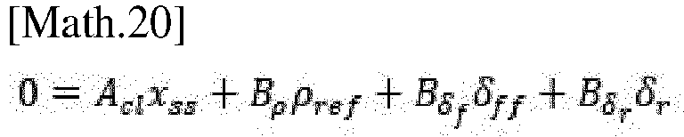
in steady state the derivatives are zero which leads to the following equation.
Avec xss le vecteur d'état associé au régime permanent.With x ss the state vector associated with the steady state.
Ledit vecteur d'état s'exprime donc :

Avec

Donc

On en déduit les valeurs du vecteur d'état :

Avec

En régime permanent l'écart transversal doit être nul.

On en déduit la valeur de

Le deuxième terme de représente alors la correction due au braquage des roues arrière.The second term then represents the correction due to the steering of the rear wheels.
La correction est donc fonction de deux facteurs de gain qui sont les facteurs de gain selon l'angle de cap relatif ψ L et selon l'angle de glissement β.The correction is therefore a function of two gain factors which are the gain factors according to the relative heading angle ψ L and according to the slip angle β .
Plus précisément, ladite correction varie dans le même sens que le gain selon l'angle de cap relatif et dans le sens opposé à la variation du gain associé à l'angle de glissement.More precisely, said correction varies in the same direction as the gain according to the relative heading angle and in the opposite direction to the variation of the gain associated with the slip angle.
La correction est proportionnelle à l'angle de braquage des roues arrière.The correction is proportional to the steering angle of the rear wheels.
La détermination de l'angle de braquage des roues avant est corrigé en ajoutant un terme due à l'angle de braquage arrière. Cette correction varie de façon linéaire avec l'angle de braquage des roues arrière. Le facteur de proportionnalité est fonction de deux facteurs de gain qui sont calculés de manière connue hors ligne avec des critères de sécurité, de confort du conducteur et de convergence des algorithmes temps réel.The determination of the front wheel steering angle is corrected by adding a term due to the rear wheel steering angle. This correction varies linearly with the rear wheel steering angle. The proportionality factor is a function of two gain factors that are calculated in a known offline manner with safety, driver comfort and convergence criteria of real-time algorithms.
Comme il va de soi, l'invention ne se limite pas aux seules formes d'exécution de cette prise, décrites ci-dessus à titre d'exemples, elle en embrasse au contraire toutes les variantes.It goes without saying that the invention is not limited to the embodiments of this socket described above as examples; on the contrary, it encompasses all variants thereof.
Claims (8)
- Advanced driver-assistance method (60) for assisting with driving a motor vehicle comprising an assistance system for controlling the front wheels and rear wheels and means for measuring the spatial position and movement of the vehicle, wherein a steering angle (δ ref) of front steered wheels of the vehicle is computed so as to keep the vehicle in a traffic lane based on a dynamic model of the vehicle, characterized in that the method comprises a correction due to steering of the rear wheels comprising the following successive steps:- a step of taking measurements of driving parameters comprising a measurement of the steering angle (δr ) of the rear wheels,- a step of determining transverse correction gain factors (K) off-line depending on driving safety criteria and on driver comfort criteria and that regard angle of friction, yaw rate, angle of relative heading and transverse deviation,- a step of determining a correction (δ 4RD ) of the steering angle of the front wheels due to steering of the rear wheels (δr), the correction being determined with the measurement of the steering angle of the rear wheels and steering correction factors (K) of the front wheels generated in the preceding step, characterized in that the correction (δ 4RD ) is dependent on the value of a slip holding gain (Kβ ), and/or a heading holding gain (Kψ L ).
- Method (60) according to Claim 1, characterized in that the correction (δ 4RD ) varies linearly with the steering angle (δ r) of the rear wheels.
- Method (60) according to either of Claims 1 and 2, characterized in that the correction (δ 4RD ) is dependent on two correction gain values (K).
- Method according to any one of Claims 1 to 5, wherein determination of the gain factors complies with driver safety criteria comprising a criterion requiring that in the steady state the error in the deviation in lateral position (YL) between the centre of gravity of the vehicle and the centre of the lane converges to a lateral error of zero, and a criterion requiring that for a set of predefined initial conditions the value of this deviation is less than a predefined set value (Δmax).
- Method (60) according to any one of Claims 1 to 6, wherein determination of the gain factors complies with driver comfort criteria comprising a criterion that requires the lateral speed of the vehicle (ẏL ) to be bounded by a value (Vmax) guaranteeing an acceptable level of comfort as perceived by the driver, and a second criterion requiring the lateral acceleration and the derivative of the yaw rate be bounded.
- Method (60) according to any one of Claims 1 to 7, wherein determination of the gain factors (K) complies with computation convergence criteria that require the minimum and maximum closed-loop convergence rates to be bounded.
- Device (100) for assisting with keeping in its lane a motor vehicle with four steered wheels comprising on the one hand at least one input for receiving at least one quantity representative of a transverse deviation (YL) between a reference path and an actual path of the vehicle, and on the other hand at least one output for producing in real time at least one steering setpoint applicable to at least one front wheel of the vehicle (1) so as to keep and/or return said vehicle to its reference path, characterized in that it comprises a module for correcting in real time said steering setpoint of the front wheels, which varies with the measurement of the steering angle of the rear wheel according to a method (60) according to Claims 1 to 8.
- Motor vehicle comprising a lane-keeping-assist device according to Claim 9.
Applications Claiming Priority (2)
| Application Number | Priority Date | Filing Date | Title |
|---|---|---|---|
| FR1911396A FR3101832B1 (en) | 2019-10-14 | 2019-10-14 | High level controller of side assistance suitable for 4WD vehicles |
| PCT/EP2020/077865 WO2021073925A1 (en) | 2019-10-14 | 2020-10-05 | High-level lateral assistance controller suitable for 4ws vehicles |
Publications (2)
| Publication Number | Publication Date |
|---|---|
| EP4045385A1 EP4045385A1 (en) | 2022-08-24 |
| EP4045385B1 true EP4045385B1 (en) | 2024-11-20 |
Family
ID=71784083
Family Applications (1)
| Application Number | Title | Priority Date | Filing Date |
|---|---|---|---|
| EP20781552.3A Active EP4045385B1 (en) | 2019-10-14 | 2020-10-05 | High-level lateral assistance controller suitable for 4ws vehicles |
Country Status (3)
| Country | Link |
|---|---|
| EP (1) | EP4045385B1 (en) |
| FR (1) | FR3101832B1 (en) |
| WO (1) | WO2021073925A1 (en) |
Families Citing this family (5)
| Publication number | Priority date | Publication date | Assignee | Title |
|---|---|---|---|---|
| CN113581176A (en) * | 2021-08-30 | 2021-11-02 | 恒大恒驰新能源汽车研究院(上海)有限公司 | Method and device for assisting vehicle in running |
| CN114394153B (en) * | 2022-01-06 | 2023-04-07 | 苏州挚途科技有限公司 | Steering wheel dummy bit state determination method and device and electronic equipment |
| CN115675636B (en) * | 2022-11-16 | 2024-11-29 | 长城汽车股份有限公司 | Front and rear wheel control method, system, electronic device, storage medium and vehicle |
| CN116803808A (en) * | 2023-06-29 | 2023-09-26 | 上海科博达智能科技有限公司 | Vehicle steering control method and device |
| CN116588193B (en) * | 2023-06-30 | 2026-01-09 | 北京易航远智科技有限公司 | Lateral control methods, devices, electronic equipment, and storage media for four-wheel steering vehicles |
Citations (3)
| Publication number | Priority date | Publication date | Assignee | Title |
|---|---|---|---|---|
| JP2013086672A (en) * | 2011-10-19 | 2013-05-13 | Nissan Motor Co Ltd | Front and rear wheel steering control device for vehicle |
| US20130261898A1 (en) * | 2010-12-20 | 2013-10-03 | Yoshitaka Fujita | Vehicle steering control apparatus |
| WO2018173317A1 (en) * | 2017-03-24 | 2018-09-27 | アイシン精機株式会社 | Vehicle |
Family Cites Families (5)
| Publication number | Priority date | Publication date | Assignee | Title |
|---|---|---|---|---|
| IT960552B (en) | 1972-04-17 | 1973-11-30 | Rocco M | SYSTEM FOR WHOLE GRAIN RECOVERY IN COMBINE HARVESTERS AND THRESHERS |
| JPS62113651A (en) | 1985-11-13 | 1987-05-25 | Nissan Motor Co Ltd | Four-wheel steering vehicle |
| DE202005018612U1 (en) | 2005-11-28 | 2007-04-12 | Wagon Automotive Gmbh | Side impact beam for a motor vehicle door |
| JP5313714B2 (en) | 2009-02-06 | 2013-10-09 | 本田技研工業株式会社 | Electric power steering device |
| FR3062359B1 (en) | 2017-02-01 | 2019-06-07 | Renault S.A.S | METHOD AND DEVICE FOR DRIVING ASSISTANCE FOR MOTOR VEHICLE |
-
2019
- 2019-10-14 FR FR1911396A patent/FR3101832B1/en active Active
-
2020
- 2020-10-05 EP EP20781552.3A patent/EP4045385B1/en active Active
- 2020-10-05 WO PCT/EP2020/077865 patent/WO2021073925A1/en not_active Ceased
Patent Citations (3)
| Publication number | Priority date | Publication date | Assignee | Title |
|---|---|---|---|---|
| US20130261898A1 (en) * | 2010-12-20 | 2013-10-03 | Yoshitaka Fujita | Vehicle steering control apparatus |
| JP2013086672A (en) * | 2011-10-19 | 2013-05-13 | Nissan Motor Co Ltd | Front and rear wheel steering control device for vehicle |
| WO2018173317A1 (en) * | 2017-03-24 | 2018-09-27 | アイシン精機株式会社 | Vehicle |
Also Published As
| Publication number | Publication date |
|---|---|
| EP4045385A1 (en) | 2022-08-24 |
| FR3101832A1 (en) | 2021-04-16 |
| WO2021073925A1 (en) | 2021-04-22 |
| FR3101832B1 (en) | 2024-08-09 |
Similar Documents
| Publication | Publication Date | Title |
|---|---|---|
| EP4045385B1 (en) | High-level lateral assistance controller suitable for 4ws vehicles | |
| EP3938260B1 (en) | Method for generating a setpoint for the combined control of a wheel-steering system and of a differential braking system of a motor vehicle | |
| EP4037947B1 (en) | Control device for a self-driving motor vehicle | |
| EP1304270B1 (en) | Vehicle stability control method using tyre lateral forces and taking into account inertia of the vehicle | |
| EP3344506B1 (en) | Device and method for correcting the direction of travel of a motor vehicle | |
| EP3947076B1 (en) | Anticipating module, associated device and method for controlling path in real time | |
| WO2021079004A1 (en) | Method for controlling a wheeled vehicle in low-grip conditions | |
| EP2043901B1 (en) | Device and method for monitoring the turn command to a steered rear wheel | |
| FR3055286A1 (en) | METHOD OF STABILIZATION BY DAMPING A CONVEYOR OF VEHICLES | |
| EP1209053B1 (en) | Active drive assist method for motor vehicle in case of a split-mu braking | |
| EP4444600B1 (en) | Train of vehicles and steering control system for such a train | |
| WO2018036723A1 (en) | Method of stabilization by orientation of a convoy of vehicles | |
| EP1544080B1 (en) | Rear wheel steering angle control system and method and corresponding vehicle | |
| EP3990324B1 (en) | Method for regulating the lateral position of a vehicle | |
| FR2915447A1 (en) | Reference yaw rate determining method for motor vehicle, involves operating bicycle model derivative of yaw rate depending on yaw torque subjected by vehicle and corrective action depending on lateral speed of vehicle | |
| EP2141036A1 (en) | Roll correction method and system for an automobile | |
| EP2032415B1 (en) | Method and system for controlling the steering of a steered rear wheel and corresponding vehicle | |
| FR2813576A1 (en) | Method of detecting wheel adhesion loss for motor vehicle with power steering involves using steering angle and servo output values to predict slippage | |
| WO2024104837A1 (en) | Method for driving a motor vehicle in the centre of its traffic lane | |
| FR2888810A1 (en) | METHOD FOR CONTROLLING THE DIRECTIONAL ORIENTATION OF A VEHICLE | |
| EP1541435A1 (en) | Vehicle deceleration control method using braking torques distributed in a limited asymmetric way | |
| FR2900369A1 (en) | METHOD AND DEVICE FOR CONTROLLING AN ACTIVE ANTI-ROLL SYSTEM OF A MOTOR VEHICLE | |
| EP1706307B1 (en) | Rear wheel steering angle control system and method and corresponding vehicle | |
| EP1738991B1 (en) | System and method to control the steering of the rear wheels of a motor vehicle with four-wheel steering | |
| FR3142422A1 (en) | Method of assisting the piloting of a motor vehicle to realign it parallel to an ideal trajectory, associated device and vehicle. |
Legal Events
| Date | Code | Title | Description |
|---|---|---|---|
| STAA | Information on the status of an ep patent application or granted ep patent |
Free format text: STATUS: UNKNOWN |
|
| STAA | Information on the status of an ep patent application or granted ep patent |
Free format text: STATUS: THE INTERNATIONAL PUBLICATION HAS BEEN MADE |
|
| PUAI | Public reference made under article 153(3) epc to a published international application that has entered the european phase |
Free format text: ORIGINAL CODE: 0009012 |
|
| STAA | Information on the status of an ep patent application or granted ep patent |
Free format text: STATUS: REQUEST FOR EXAMINATION WAS MADE |
|
| 17P | Request for examination filed |
Effective date: 20220413 |
|
| AK | Designated contracting states |
Kind code of ref document: A1 Designated state(s): AL AT BE BG CH CY CZ DE DK EE ES FI FR GB GR HR HU IE IS IT LI LT LU LV MC MK MT NL NO PL PT RO RS SE SI SK SM TR |
|
| DAV | Request for validation of the european patent (deleted) | ||
| DAX | Request for extension of the european patent (deleted) | ||
| P01 | Opt-out of the competence of the unified patent court (upc) registered |
Effective date: 20230608 |
|
| RAP1 | Party data changed (applicant data changed or rights of an application transferred) |
Owner name: AMPERE SAS |
|
| GRAP | Despatch of communication of intention to grant a patent |
Free format text: ORIGINAL CODE: EPIDOSNIGR1 |
|
| GRAP | Despatch of communication of intention to grant a patent |
Free format text: ORIGINAL CODE: EPIDOSNIGR1 |
|
| STAA | Information on the status of an ep patent application or granted ep patent |
Free format text: STATUS: GRANT OF PATENT IS INTENDED |
|
| INTG | Intention to grant announced |
Effective date: 20240614 |
|
| RIC1 | Information provided on ipc code assigned before grant |
Ipc: B60W 40/10 20120101ALI20240603BHEP Ipc: B62D 7/15 20060101ALI20240603BHEP Ipc: B62D 6/04 20060101ALI20240603BHEP Ipc: B60W 30/02 20120101ALI20240603BHEP Ipc: B62D 6/00 20060101AFI20240603BHEP |
|
| GRAS | Grant fee paid |
Free format text: ORIGINAL CODE: EPIDOSNIGR3 |
|
| GRAA | (expected) grant |
Free format text: ORIGINAL CODE: 0009210 |
|
| STAA | Information on the status of an ep patent application or granted ep patent |
Free format text: STATUS: THE PATENT HAS BEEN GRANTED |
|
| AK | Designated contracting states |
Kind code of ref document: B1 Designated state(s): AL AT BE BG CH CY CZ DE DK EE ES FI FR GB GR HR HU IE IS IT LI LT LU LV MC MK MT NL NO PL PT RO RS SE SI SK SM TR |
|
| REG | Reference to a national code |
Ref country code: GB Ref legal event code: FG4D Free format text: NOT ENGLISH |
|
| REG | Reference to a national code |
Ref country code: CH Ref legal event code: EP |
|
| REG | Reference to a national code |
Ref country code: DE Ref legal event code: R096 Ref document number: 602020041727 Country of ref document: DE |
|
| REG | Reference to a national code |
Ref country code: IE Ref legal event code: FG4D Free format text: LANGUAGE OF EP DOCUMENT: FRENCH |
|
| REG | Reference to a national code |
Ref country code: LT Ref legal event code: MG9D |
|
| REG | Reference to a national code |
Ref country code: NL Ref legal event code: MP Effective date: 20241120 |
|
| PG25 | Lapsed in a contracting state [announced via postgrant information from national office to epo] |
Ref country code: PT Free format text: LAPSE BECAUSE OF FAILURE TO SUBMIT A TRANSLATION OF THE DESCRIPTION OR TO PAY THE FEE WITHIN THE PRESCRIBED TIME-LIMIT Effective date: 20250320 Ref country code: IS Free format text: LAPSE BECAUSE OF FAILURE TO SUBMIT A TRANSLATION OF THE DESCRIPTION OR TO PAY THE FEE WITHIN THE PRESCRIBED TIME-LIMIT Effective date: 20250320 Ref country code: HR Free format text: LAPSE BECAUSE OF FAILURE TO SUBMIT A TRANSLATION OF THE DESCRIPTION OR TO PAY THE FEE WITHIN THE PRESCRIBED TIME-LIMIT Effective date: 20241120 |
|
| PG25 | Lapsed in a contracting state [announced via postgrant information from national office to epo] |
Ref country code: NL Free format text: LAPSE BECAUSE OF FAILURE TO SUBMIT A TRANSLATION OF THE DESCRIPTION OR TO PAY THE FEE WITHIN THE PRESCRIBED TIME-LIMIT Effective date: 20241120 Ref country code: FI Free format text: LAPSE BECAUSE OF FAILURE TO SUBMIT A TRANSLATION OF THE DESCRIPTION OR TO PAY THE FEE WITHIN THE PRESCRIBED TIME-LIMIT Effective date: 20241120 |
|
| REG | Reference to a national code |
Ref country code: AT Ref legal event code: MK05 Ref document number: 1743350 Country of ref document: AT Kind code of ref document: T Effective date: 20241120 |
|
| PG25 | Lapsed in a contracting state [announced via postgrant information from national office to epo] |
Ref country code: BG Free format text: LAPSE BECAUSE OF FAILURE TO SUBMIT A TRANSLATION OF THE DESCRIPTION OR TO PAY THE FEE WITHIN THE PRESCRIBED TIME-LIMIT Effective date: 20241120 |
|
| PG25 | Lapsed in a contracting state [announced via postgrant information from national office to epo] |
Ref country code: ES Free format text: LAPSE BECAUSE OF FAILURE TO SUBMIT A TRANSLATION OF THE DESCRIPTION OR TO PAY THE FEE WITHIN THE PRESCRIBED TIME-LIMIT Effective date: 20241120 |
|
| PG25 | Lapsed in a contracting state [announced via postgrant information from national office to epo] |
Ref country code: NO Free format text: LAPSE BECAUSE OF FAILURE TO SUBMIT A TRANSLATION OF THE DESCRIPTION OR TO PAY THE FEE WITHIN THE PRESCRIBED TIME-LIMIT Effective date: 20250220 |
|
| PG25 | Lapsed in a contracting state [announced via postgrant information from national office to epo] |
Ref country code: LV Free format text: LAPSE BECAUSE OF FAILURE TO SUBMIT A TRANSLATION OF THE DESCRIPTION OR TO PAY THE FEE WITHIN THE PRESCRIBED TIME-LIMIT Effective date: 20241120 Ref country code: GR Free format text: LAPSE BECAUSE OF FAILURE TO SUBMIT A TRANSLATION OF THE DESCRIPTION OR TO PAY THE FEE WITHIN THE PRESCRIBED TIME-LIMIT Effective date: 20250221 Ref country code: AT Free format text: LAPSE BECAUSE OF FAILURE TO SUBMIT A TRANSLATION OF THE DESCRIPTION OR TO PAY THE FEE WITHIN THE PRESCRIBED TIME-LIMIT Effective date: 20241120 |
|
| PG25 | Lapsed in a contracting state [announced via postgrant information from national office to epo] |
Ref country code: PL Free format text: LAPSE BECAUSE OF FAILURE TO SUBMIT A TRANSLATION OF THE DESCRIPTION OR TO PAY THE FEE WITHIN THE PRESCRIBED TIME-LIMIT Effective date: 20241120 |
|
| PG25 | Lapsed in a contracting state [announced via postgrant information from national office to epo] |
Ref country code: RS Free format text: LAPSE BECAUSE OF FAILURE TO SUBMIT A TRANSLATION OF THE DESCRIPTION OR TO PAY THE FEE WITHIN THE PRESCRIBED TIME-LIMIT Effective date: 20250220 |
|
| PG25 | Lapsed in a contracting state [announced via postgrant information from national office to epo] |
Ref country code: SM Free format text: LAPSE BECAUSE OF FAILURE TO SUBMIT A TRANSLATION OF THE DESCRIPTION OR TO PAY THE FEE WITHIN THE PRESCRIBED TIME-LIMIT Effective date: 20241120 |
|
| PG25 | Lapsed in a contracting state [announced via postgrant information from national office to epo] |
Ref country code: DK Free format text: LAPSE BECAUSE OF FAILURE TO SUBMIT A TRANSLATION OF THE DESCRIPTION OR TO PAY THE FEE WITHIN THE PRESCRIBED TIME-LIMIT Effective date: 20241120 |
|
| PG25 | Lapsed in a contracting state [announced via postgrant information from national office to epo] |
Ref country code: EE Free format text: LAPSE BECAUSE OF FAILURE TO SUBMIT A TRANSLATION OF THE DESCRIPTION OR TO PAY THE FEE WITHIN THE PRESCRIBED TIME-LIMIT Effective date: 20241120 |
|
| PG25 | Lapsed in a contracting state [announced via postgrant information from national office to epo] |
Ref country code: RO Free format text: LAPSE BECAUSE OF FAILURE TO SUBMIT A TRANSLATION OF THE DESCRIPTION OR TO PAY THE FEE WITHIN THE PRESCRIBED TIME-LIMIT Effective date: 20241120 |
|
| PG25 | Lapsed in a contracting state [announced via postgrant information from national office to epo] |
Ref country code: SK Free format text: LAPSE BECAUSE OF FAILURE TO SUBMIT A TRANSLATION OF THE DESCRIPTION OR TO PAY THE FEE WITHIN THE PRESCRIBED TIME-LIMIT Effective date: 20241120 |
|
| PG25 | Lapsed in a contracting state [announced via postgrant information from national office to epo] |
Ref country code: CZ Free format text: LAPSE BECAUSE OF FAILURE TO SUBMIT A TRANSLATION OF THE DESCRIPTION OR TO PAY THE FEE WITHIN THE PRESCRIBED TIME-LIMIT Effective date: 20241120 |
|
| PG25 | Lapsed in a contracting state [announced via postgrant information from national office to epo] |
Ref country code: IT Free format text: LAPSE BECAUSE OF FAILURE TO SUBMIT A TRANSLATION OF THE DESCRIPTION OR TO PAY THE FEE WITHIN THE PRESCRIBED TIME-LIMIT Effective date: 20241120 |
|
| REG | Reference to a national code |
Ref country code: DE Ref legal event code: R097 Ref document number: 602020041727 Country of ref document: DE |
|
| PG25 | Lapsed in a contracting state [announced via postgrant information from national office to epo] |
Ref country code: SE Free format text: LAPSE BECAUSE OF FAILURE TO SUBMIT A TRANSLATION OF THE DESCRIPTION OR TO PAY THE FEE WITHIN THE PRESCRIBED TIME-LIMIT Effective date: 20241120 |
|
| PLBE | No opposition filed within time limit |
Free format text: ORIGINAL CODE: 0009261 |
|
| STAA | Information on the status of an ep patent application or granted ep patent |
Free format text: STATUS: NO OPPOSITION FILED WITHIN TIME LIMIT |
|
| 26N | No opposition filed |
Effective date: 20250821 |
|
| PGFP | Annual fee paid to national office [announced via postgrant information from national office to epo] |
Ref country code: DE Payment date: 20251021 Year of fee payment: 6 |
|
| PGFP | Annual fee paid to national office [announced via postgrant information from national office to epo] |
Ref country code: FR Payment date: 20251030 Year of fee payment: 6 |