EP2714308B1 - Machine tool - Google Patents
Machine tool Download PDFInfo
- Publication number
- EP2714308B1 EP2714308B1 EP12721853.5A EP12721853A EP2714308B1 EP 2714308 B1 EP2714308 B1 EP 2714308B1 EP 12721853 A EP12721853 A EP 12721853A EP 2714308 B1 EP2714308 B1 EP 2714308B1
- Authority
- EP
- European Patent Office
- Prior art keywords
- tool
- carrier
- spindle
- tool carrier
- machine
- Prior art date
- Legal status (The legal status is an assumption and is not a legal conclusion. Google has not performed a legal analysis and makes no representation as to the accuracy of the status listed.)
- Active
Links
- 238000003754 machining Methods 0.000 claims description 20
- 101100317264 Caenorhabditis elegans wts-1 gene Proteins 0.000 claims description 14
- 239000000969 carrier Substances 0.000 claims description 9
- 238000010276 construction Methods 0.000 description 8
- 238000005553 drilling Methods 0.000 description 2
- 238000000034 method Methods 0.000 description 2
- 238000003801 milling Methods 0.000 description 2
- 238000012800 visualization Methods 0.000 description 2
- 230000001419 dependent effect Effects 0.000 description 1
- 238000007373 indentation Methods 0.000 description 1
- 230000001681 protective effect Effects 0.000 description 1
Images


Classifications
-
- B—PERFORMING OPERATIONS; TRANSPORTING
- B23—MACHINE TOOLS; METAL-WORKING NOT OTHERWISE PROVIDED FOR
- B23B—TURNING; BORING
- B23B29/00—Holders for non-rotary cutting tools; Boring bars or boring heads; Accessories for tool holders
- B23B29/24—Tool holders for a plurality of cutting tools, e.g. turrets
- B23B29/242—Turrets, without description of the angular positioning device
-
- B—PERFORMING OPERATIONS; TRANSPORTING
- B23—MACHINE TOOLS; METAL-WORKING NOT OTHERWISE PROVIDED FOR
- B23B—TURNING; BORING
- B23B3/00—General-purpose turning-machines or devices, e.g. centre lathes with feed rod and lead screw; Sets of turning-machines
- B23B3/16—Turret lathes for turning individually-chucked workpieces
- B23B3/167—Turret lathes for turning individually-chucked workpieces lathe with two or more toolslides carrying turrets
- B23B3/168—Arrangements for performing other machining operations, e.g. milling, drilling
-
- B—PERFORMING OPERATIONS; TRANSPORTING
- B23—MACHINE TOOLS; METAL-WORKING NOT OTHERWISE PROVIDED FOR
- B23B—TURNING; BORING
- B23B3/00—General-purpose turning-machines or devices, e.g. centre lathes with feed rod and lead screw; Sets of turning-machines
- B23B3/30—Turning-machines with two or more working-spindles, e.g. in fixed arrangement
-
- B—PERFORMING OPERATIONS; TRANSPORTING
- B23—MACHINE TOOLS; METAL-WORKING NOT OTHERWISE PROVIDED FOR
- B23Q—DETAILS, COMPONENTS, OR ACCESSORIES FOR MACHINE TOOLS, e.g. ARRANGEMENTS FOR COPYING OR CONTROLLING; MACHINE TOOLS IN GENERAL CHARACTERISED BY THE CONSTRUCTION OF PARTICULAR DETAILS OR COMPONENTS; COMBINATIONS OR ASSOCIATIONS OF METAL-WORKING MACHINES, NOT DIRECTED TO A PARTICULAR RESULT
- B23Q39/00—Metal-working machines incorporating a plurality of sub-assemblies, each capable of performing a metal-working operation
- B23Q39/02—Metal-working machines incorporating a plurality of sub-assemblies, each capable of performing a metal-working operation the sub-assemblies being capable of being brought to act at a single operating station
- B23Q39/021—Metal-working machines incorporating a plurality of sub-assemblies, each capable of performing a metal-working operation the sub-assemblies being capable of being brought to act at a single operating station with a plurality of toolheads per workholder, whereby the toolhead is a main spindle, a multispindle, a revolver or the like
- B23Q39/025—Metal-working machines incorporating a plurality of sub-assemblies, each capable of performing a metal-working operation the sub-assemblies being capable of being brought to act at a single operating station with a plurality of toolheads per workholder, whereby the toolhead is a main spindle, a multispindle, a revolver or the like with different working directions of toolheads on same workholder
- B23Q39/026—Metal-working machines incorporating a plurality of sub-assemblies, each capable of performing a metal-working operation the sub-assemblies being capable of being brought to act at a single operating station with a plurality of toolheads per workholder, whereby the toolhead is a main spindle, a multispindle, a revolver or the like with different working directions of toolheads on same workholder simultaneous working of toolheads
-
- B—PERFORMING OPERATIONS; TRANSPORTING
- B23—MACHINE TOOLS; METAL-WORKING NOT OTHERWISE PROVIDED FOR
- B23B—TURNING; BORING
- B23B2270/00—Details of turning, boring or drilling machines, processes or tools not otherwise provided for
- B23B2270/14—Constructions comprising exactly two similar components
-
- B—PERFORMING OPERATIONS; TRANSPORTING
- B23—MACHINE TOOLS; METAL-WORKING NOT OTHERWISE PROVIDED FOR
- B23Q—DETAILS, COMPONENTS, OR ACCESSORIES FOR MACHINE TOOLS, e.g. ARRANGEMENTS FOR COPYING OR CONTROLLING; MACHINE TOOLS IN GENERAL CHARACTERISED BY THE CONSTRUCTION OF PARTICULAR DETAILS OR COMPONENTS; COMBINATIONS OR ASSOCIATIONS OF METAL-WORKING MACHINES, NOT DIRECTED TO A PARTICULAR RESULT
- B23Q39/00—Metal-working machines incorporating a plurality of sub-assemblies, each capable of performing a metal-working operation
- B23Q2039/002—Machines with twin spindles
-
- B—PERFORMING OPERATIONS; TRANSPORTING
- B23—MACHINE TOOLS; METAL-WORKING NOT OTHERWISE PROVIDED FOR
- B23Q—DETAILS, COMPONENTS, OR ACCESSORIES FOR MACHINE TOOLS, e.g. ARRANGEMENTS FOR COPYING OR CONTROLLING; MACHINE TOOLS IN GENERAL CHARACTERISED BY THE CONSTRUCTION OF PARTICULAR DETAILS OR COMPONENTS; COMBINATIONS OR ASSOCIATIONS OF METAL-WORKING MACHINES, NOT DIRECTED TO A PARTICULAR RESULT
- B23Q39/00—Metal-working machines incorporating a plurality of sub-assemblies, each capable of performing a metal-working operation
- B23Q2039/004—Machines with tool turrets
-
- B—PERFORMING OPERATIONS; TRANSPORTING
- B23—MACHINE TOOLS; METAL-WORKING NOT OTHERWISE PROVIDED FOR
- B23Q—DETAILS, COMPONENTS, OR ACCESSORIES FOR MACHINE TOOLS, e.g. ARRANGEMENTS FOR COPYING OR CONTROLLING; MACHINE TOOLS IN GENERAL CHARACTERISED BY THE CONSTRUCTION OF PARTICULAR DETAILS OR COMPONENTS; COMBINATIONS OR ASSOCIATIONS OF METAL-WORKING MACHINES, NOT DIRECTED TO A PARTICULAR RESULT
- B23Q39/00—Metal-working machines incorporating a plurality of sub-assemblies, each capable of performing a metal-working operation
- B23Q2039/008—Machines of the lathe type
-
- Y—GENERAL TAGGING OF NEW TECHNOLOGICAL DEVELOPMENTS; GENERAL TAGGING OF CROSS-SECTIONAL TECHNOLOGIES SPANNING OVER SEVERAL SECTIONS OF THE IPC; TECHNICAL SUBJECTS COVERED BY FORMER USPC CROSS-REFERENCE ART COLLECTIONS [XRACs] AND DIGESTS
- Y10—TECHNICAL SUBJECTS COVERED BY FORMER USPC
- Y10T—TECHNICAL SUBJECTS COVERED BY FORMER US CLASSIFICATION
- Y10T82/00—Turning
- Y10T82/25—Lathe
- Y10T82/2508—Lathe with tool turret
-
- Y—GENERAL TAGGING OF NEW TECHNOLOGICAL DEVELOPMENTS; GENERAL TAGGING OF CROSS-SECTIONAL TECHNOLOGIES SPANNING OVER SEVERAL SECTIONS OF THE IPC; TECHNICAL SUBJECTS COVERED BY FORMER USPC CROSS-REFERENCE ART COLLECTIONS [XRACs] AND DIGESTS
- Y10—TECHNICAL SUBJECTS COVERED BY FORMER USPC
- Y10T—TECHNICAL SUBJECTS COVERED BY FORMER US CLASSIFICATION
- Y10T82/00—Turning
- Y10T82/25—Lathe
- Y10T82/2524—Multiple
Definitions
- the present invention relates to a machine tool, in particular a lathe, comprising a machine frame, a first work spindle arranged on a first support section of the machine frame for receiving a first workpiece, a second work spindle facing the first work spindle and arranged on a second support section of the machine frame for receiving a second workpiece , wherein the spindle axis of the second work spindle is aligned parallel, in particular coaxially, to the spindle axis of the first work spindle, and at least two movable tool carrier slide, on each of which a tool-carrying tool carrier is arranged.
- Generic machine tools comprise a machine frame on which at least two mutually facing, rotatably mounted work spindles are provided with parallel or coaxial spindle axes, wherein on the work spindles in each case workpieces can be received for processing on the machine tool.
- At least two tool carriers are provided for the provision of the tools for machining, which are arranged on the machine frame, movable tool slide, in particular cross slide, and can be moved by means of one or more linear axes relative to the work spindles (eg in X, Y or Z-direction movable).
- Such generic machine tools are eg from the DD 279 429 A1 or even the EP 0 999 002 A1 known.
- the invention is therefore an object of the invention to improve a machine tool of the generic type such that efficient processing of workpieces with as many as possible simultaneously usable tools with the greatest possible flexibility with respect to the control of the relative movements between the tools and recorded in the work spindles Tools is possible, while compact and cost-effective design of the machine tool and with as possible for the operator or operator of the machine tool viewable processing space.
- US 5,127,140 relates to a numerically controlled lathe with two spindles and three tool holders, wherein two headstocks are arranged opposite each other, and wherein each of the tool holders is movable in two directions.
- EP 1897 640 A1 relates to a numerically controlled lathe with two spindles and three tool holders formed as a turret, wherein two headstocks are arranged opposite each other.
- a machine tool in particular a lathe, which comprises a machine frame with a first tool carrier side having a first support portion, a second tool carrier side having second support portion and a disposed between the first and second support portion central portion having a third tool carrier side.
- the first tool carrier side of the first carrier portion and the second tool carrier side of the second carrier portion are arranged on a same first side of the machine frame, and the third tool carrier side of the central portion is arranged on a second side of the machine frame.
- the machine tool comprises a first work spindle arranged on the first support section for receiving a first workpiece and a second work spindle facing the first work spindle and arranged on the second support section for receiving a second workpiece.
- the spindle axis of the second Working spindle parallel, in particular coaxial, aligned with the spindle axis of the first work spindle.
- the machine tool further comprises a first tool carrier carriage arranged on the first tool carrier side of the first carrier section, on which a first tool carrier is arranged, a second tool carrier carriage arranged on the second tool carrier side of the second carrier section, on which a second tool carrier is arranged, and arranged on the third tool carrier side of the central portion third horrachschlitten on which a third tool carrier is arranged.
- the third tool carriage is transversely movable in a first direction, in particular perpendicular, to the spindle axes of the first and second work spindles, and the third tool carrier is arranged between the first work spindle and the second work spindle.
- the invention is thus based on the idea to form a geometry of a machine frame of the machine tool so advantageous that a plurality of tool carriage with tool carriers and two coaxial, in particular parallel, arranged work spindles can be arranged compact by a first support portion of the machine frame both a first Carrier carrying first tool carriage as well as a first work spindle carries, a second support portion of the machine frame carries both a second tool carrier carrying a second tool carriage and a second work spindle, and a third tool carrier carrying third tool carriage at a disposed between the first and the second support portion third Carrier portion of the machine frame is arranged, such that the third tool carrier is disposed between the work spindles.
- the machine tool according to the invention permits efficient machining of the workpieces with as many as possible tools that can be used at the same time, since three tool carriers for machining the workpieces on the work spindles are available in a compact manner, with extremely high flexibility with regard to the control of the three separately controllable tool slides Relative movements between the tools and recorded in the spindles tools is made possible.
- an extremely compact and cost-effective design of the machine tool can be provided with a processing space which is very clearly visible to the processor or operator of the machine tool.
- the first and / or second work spindle in the direction of the spindle axes is movable. This advantageously allows workpieces to be transferred from one spindle to another, e.g. in successive execution of front and back side machining of the same workpiece on the two work spindles.
- the first tool carrier side of the first carrier section and the second tool carrier side of the second carrier section essentially clamp a first plane and the third tool carrier side of the central section essentially spans a second plane oriented obliquely to the first plane.
- a special functional design of the machine frame are provided with two perpendicular or oblique planes, in which each of the levels can be used as a tool carrier side to arrange tool carrier carrying tool carriage.
- the side of the machine frame of the one level on the first and second support sections may optionally be used as the spindle carrier side, and the side of the machine frame of the other plane on the first and second support sections can be used as the tool carrier side for the first and / or third tool carrier carriages.
- the main body of the machine frame have exactly planar sides that span said planes. Rather, the above-mentioned levels can be understood more abstractly than geometric planes that essentially correspond to the sides of the machine frame or are essentially spanned by the respective sides of the machine frame, or at least in which the travel planes of the carriages lie, for example by guide rails of the carriages Trays are trained or clamped.
- the second plane is engaged relative to the arranged on the second side of the machine frame sides of the first and second support portion to the machine frame out.
- a machine frame construction or a machine frame structure can be provided in which the third tool carriage for the third tool carrier can be arranged compactly in a depression between the work spindles or between the support sections of the machine frame.
- a clearly visible, opened in the direction of disclosure or unilaterally open processing space can be created. This processing space can be particularly advantageously limited to three sides in each case from the sides of the first, middle and second carrier section.
- a particularly expedient fall path for chips underneath the work spindles and the tool carrier can furthermore be created in this design.
- a side of the first carrier section facing the second carrier section, the third tool carrier side of the central section and a side of the second carrier section facing the first carrier section preferably form the processing space in the machine frame.
- the first work spindle is arranged on the first tool carrier side of the first carrier section and / or the second work spindle is arranged on the second tool carrier side of the first carrier portion.
- the first work spindle is arranged on a first spindle carrier side of the first carrier section and / or the second work spindle is arranged on a second spindle carrier side of the second carrier section.
- the first spindle carrier side and the second spindle carrier side may preferably be arranged on the same second side of the machine frame as the third tool carrier side.
- the first spindle carrier side of the first carrier section and the second spindle carrier side of the second carrier section essentially span a third plane, such that the first plane is aligned substantially perpendicularly or obliquely to the third plane.
- a machine frame construction or a machine frame structure can be provided in a particularly expedient and compact manner, in which the third tool carriage for the third tool carrier is compactly defined in a recess (which optionally may define a processing space in the machine frame as described above) between the two tool carriers Working spindles or between the support portions of the machine frame can be arranged.
- the third tool carriage is guided on guides, in particular guide rails, which are arranged or fastened on the third tool carrier side of the middle section of the machine frame and are aligned in the first direction.
- the first and / or second horritten parallel or transverse, in particular perpendicular, movable to the spindle axes.
- the first and / or the second tool carrier carriage can in this case preferably as a cross slide with two partial carriage or double cross slide may be formed with three partial carriages.
- the first and / or second tool carrier is movable transversely to the spindle axes in the first direction, movable in a second direction transversely to the first direction and transversely to the spindle axes and / or movable in a third direction parallel to the spindle axes.
- the first and / or the second tool carrier carriage may in this case preferably be designed as a cross slide with two partial carriages or double cross slides with three partial carriages.
- the first and / or second tool carrier is preferably designed as a tool turret, which comprises a tool-carrying turret rotatably mounted about a turret axis oriented parallel to the spindle axes.
- the third tool carrier preferably comprises at least one tool turret. Since each turret is adapted to provide a plurality of tools, tooling on the machine tool can be further improved thereby.
- the first and second tool carrier are arranged substantially on a same side of the spindle axes.
- the construction of the machine tool can be further advantageously provided even more compact.
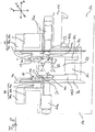
- Fig. 1 shows by way of example a schematic representation of a perspective view of the machine frame structure of the machine tool according to a preferred embodiment of the present invention.
- the first carrier section 1a has, for example, a first front side VS1 and a first tool carrier side WTS1, which lie essentially in mutually perpendicular planes.
- the second carrier section 1 b has, analogously to the first carrier section 1 a, a second front side VS 2 and a second tool carrier side WTS 2, which lie essentially in mutually perpendicular planes.
- the first tool carrier side WTS1 of the first carrier section 1a and the second tool carrier side WTS2 of the second carrier section 1b substantially span a first plane
- the first front side VS1 of the first carrier section 1a and the second front side VS2 of the second carrier section 1b span substantially a second plane wherein the first plane is oriented, for example, substantially perpendicular to the second plane.
- the first plane may also be aligned obliquely to the second plane in other embodiments.
- the first tool support side WTS1 of the first support portion 1a and the second tool support side WTS2 of the second support portion 1b are arranged on the upper side of the machine frame 1, and the first front side VS1 of the first support portion 1a and the second front support side VS2 of the second support portion 1b are on the front side of the machine frame 1 is arranged.
- the machine frame On the lower side, the machine frame has a machine base section MB, which has a footprint for the machine tool.
- the machine frame can also be oriented differently, for example, such that the tool carrier sides WTS1 and WTS2 are arranged on the front or rear side of the frame 1.
- the middle section 1c of the machine frame 1 arranged between the support sections 1a and 1b has a third tool carrier side WTS3.
- the third tool carrier side WTS3 of the central portion 1c substantially biases a third plane parallel to the second plane of the first and second front sides VS1 and VS2, the third plane being engaged with the machine frame 1 relative to the second plane of the first and second front sides VS1 and VS2 ie in particular parallel to the machine frame 1 out.
- the first tool carrier side WTS1 of the first carrier section 1a and the second tool carrier side WTS2 of the second carrier section 1b are arranged, for example, on the upper side of the machine frame 1, and the first front side VS1 of the first carrier section 1a, the second front side VS2 of the second support portion 1b and the third tool support side WTS3 of the center portion 1c are arranged, for example, on the front side of the machine frame 1, from which the operator looks into the processing space.
- the processing space is defined by the middle support portion 1c being engaged between the first and second support portions 1a and 1b toward the machine frame 1 so as to provide a processing space opened forward (in the direction transverse to the second plane).
- respective machining space sides BS1 and BS2 extend (see, eg, page BS1 in FIG Fig. 1 ; see also Fig. 2 ), which are aligned, for example, perpendicular to the first plane of the first and second tool carrier sides WTS1 and WTS2 of the carrier sections 1a and 1b and transversely, in particular perpendicular, to the second plane of the first and second front sides VS1 and VS2 of the carrier sections 1a and 1b.
- the support portions 1a to 1c are interconnected, and may be provided separately from each other.
- Fig. 2 by way of example shows a schematic representation of a front view of a machine tool according to a first embodiment of the present invention.
- the machine tool according to Fig. 1 is a lathe with a machine frame 1 having a first support portion 1a, a second support portion 1b, and a middle portion 1c interposed between the first and second support portions 1a and 1b as shown in FIG Fig. 1 shown schematically.
- the spindles 21 and 22 are arranged, for example, respectively on the tool carriage sides WTS1 and WTS2 of the first and second support portions 1a and 1b.
- the spindles 21 and 22 can also be arranged on the front sides VS1 and VS2.
- the machine tool according to Fig. 2 includes a first held on the first tool carriage side WTS1 of the first support portion 1a, held on a spindle housing 21a first Work spindle 21 for receiving a first workpiece W1 and one of the first work spindle 21 facing, on the second tool carriage side WTS2 of the second support portion 1b arranged second work spindle 22 for receiving a second workpiece W2.
- the second work spindle 22 is held on a spindle housing 22a.
- the spindle axis of the second work spindle 22 is aligned coaxially with the spindle axis of the first work spindle 21 in this embodiment, but may also be parallel, but not coaxially aligned, or be aligned in parallel and be coaxially alignable by methods.
- the first work spindle 21 is arranged in the spindle housing 21a on a run on guides 21b spindle slide 21c and in the direction Z (Z MS , MS for "Main Spindle” or main spindle) parallel to the spindle axes and also the second work spindle 22, which is guided in the spindle housing 22a on a guided by guides 22b spindle slide 22c, in the direction Z (Zcs, CS for "Counter Spindle” or counterspindle) parallel to the spindle axes movable.
- Z MS Main Spindle
- CS Counter Spindle
- the guides 21b and 22b respectively run on the first tool carriage side WTS1 of the first carrier section 1a and on the second tool carriage side WTS2 of the second carrier section 1b, but can alternatively also be arranged on the front sides VS1 or VS2 or on projection sections of the machine frame 1 be, which can be arranged on the front sides VS1 and VS2.
- the machine tool further comprises a first tool carrier carriage 51 arranged on the first tool carrier side WTS1 of the first carrier section 1a, on which a first tool carrier 61 is arranged, and a second tool carrier carriage 53 arranged on the second tool carrier side WTS2 of the second carrier section 1b, on which a second tool carrier 63 is arranged.
- the first and the second tool carrier 61 and 63 are formed in this embodiment as a tool turret, each comprising a rotatably mounted about a parallel to the spindle axes turret axis, tool-carrying turret.
- a tool turret instead of a tool turret, it is also possible, for example, to provide a milling / drilling spindle with a tool holder for the first and / or second tool carrier 61, 63.
- a third tool carrier slide 52 arranged on the third tool carrier side WTS3 of the middle section 1c is provided, on which a third tool carrier 62 is arranged.
- the third tool carrier carriage 52 is in the vertical direction X2 in Fig. 2 and in particular perpendicular to the spindle axes of the first and second working spindles 21 and 22 movable.
- WTS3 guides 72a are arranged, which are aligned transversely to the spindle axes in the vertical direction X2.
- the third tool carrier 62 is also movable in a further direction Y2 transverse to the spindle axes and transverse to the direction X2.
- the third tool carrier 62 is configured to include two tool turrets having respective turrets 62A and 62B disposed between the first work spindle 21 and the second work spindle 22.
- Each of the turrets 62A and 62B is rotatably mounted on the tool carrier 62 about a respective turret axis.
- the turret axes of the turrets 62A and 62B are coaxially aligned, by way of example, in this embodiment.
- the housing 52a comprises a Drehachsantrieb a rotational axis B, by means of which the third tool carrier 62 is rotatable about an axis which is aligned transversely to the spindle axes and parallel to the direction Y2 and transverse to the direction X2.
- the turrets 62A and 62B are arranged in this case such that the turret axes are aligned transversely to the axis of rotation B.
- the turrets 62A and 62B are disposed on respective sides opposite to the rotation axis B on the third tool carrier 62.
- Fig. 3 shows by way of example a schematic representation of a plan view of the machine tool according to the first preferred embodiment of the present invention Fig. 2 , Here, in particular, the construction of the tool carrier carriages 51 and 52 is shown.
- the first tool carrier carriage 51 is designed as a double cross slide comprising three partial carriages 51d, 51a and 51b, wherein the partial carriage 51d is arranged on the first carrier section 1a of the machine frame 1 and guided on guides 71a which are parallel to the spindle axes on the first tool carrier side WTS1 of the first carrier portion 1a are arranged.
- the partial carriage 51d is thus in a direction ZI (see also Fig . 2 ) movable.
- guides 71b are arranged, which extend transversely to the spindle axes and on which the partial carriage 51a in the direction Y1 (see also Fig. 2 ) is guided movably.
- guides 71c are arranged, which are transverse to the spindle axes and transverse to Direction Y1 of the guides 71b and on which the partial carriage 51b in the direction X1 (see also Fig. 2 ) is guided movably.
- a housing 51c which extends parallel to the spindle axes into the processing space and at the end of which the first tool carrier 61 is held, is held on the partial carriage 51b. Due to this construction, the first tool carrier 61 can be moved in three orthogonal directions X1, Y1 and Z1.
- the second tool carrier carriage 53 is executed according to this embodiment as a double cross slide comprising three sub-slides 53d, 53a and 53b, wherein the sub-carriage 53d is disposed on the second support portion 1b of the machine frame 1 and guided on guides 73a, which are parallel to the spindle axes the second tool carrier side WTS2 of the second carrier portion 1b are arranged.
- the partial carriage 53d is thus in a direction Z3 (see also Fig. 2 ) movable.
- guides 73b are arranged, which extend transversely to the spindle axes and on which the partial carriage 53a in the direction Y3 (see also Fig. 2 ) is guided movably.
- Fig. 4 shows by way of example a schematic representation of a detailed view of the processing space of the machine tool according to the first preferred embodiment of the present invention Figs. 2 and 3 ,
- the first and second tool carriers in this exemplary embodiment are designed as tool turrets with respective turrets 61 and 63.
- the turrets 61 and 63 are in this case aligned such that the turret axes are aligned parallel to each other and parallel to the spindle axes.
- the respective tool holders 61a By rotating the turret 61 about the turret axis, the respective tool holders 61a can be aligned with the first work spindle 21 to machine a workpiece W1 held therein.
- a drive of the tool turret may be arranged in the housing 51c.
- the turret 63 of the second tool carrier circumferentially around the turret axis a plurality of tool holders 63 a arranged, which are each adapted to hold tools T for machining a workpiece.
- the respective tool holder 63a By rotation of the Turret 63 about the turret axis, the respective tool holder 63a can be aligned with the second work spindle 22 to machine a held therein workpiece W2.
- a drive of the tool turret may be arranged in the housing 53c.
- a plurality of tool holders 62a which are each adapted to hold tools T for machining a workpiece.
- the respective tool holders 62a can be aligned with the first work spindle 21 (or also with the second work spindle 22) to machine a workpiece W1 or W2 held therein.
- a tool of the tool turret 62A is aligned with the first work spindle 21, so that the workpiece W1 held therein can be processed both by a tool of the tool turret 62A and at the same time by a tool of the tool turret 61.
- a workpiece W2 held on the second work spindle 22 can be machined by means of a tool of the tool turret 63.
- a plurality of tool holders 62b are arranged circumferentially around the turret axis, each being adapted to hold tools T for machining a workpiece.
- the respective tool holders 62b can be aligned with the second work spindle 22 (or also with the first work spindle 21) to machine a workpiece W2 or W1 held therein.
- both the first tool carrier 61 and the first work spindle 21 and the second tool carrier 63 and the second work spindle 22 are each independently movable in the direction parallel to the spindle axes (see for example the two arrows in FIG Fig. 4 for spindle 21 and tool carrier 61, or directions Z MS and ZI or Zcs and Z3 in Fig . 2 ).
- the relative position in the direction of the spindle axes between workpiece W1 on the first work spindle 21 and a tool on the turret 62A of the third Tool carrier 62 can be controlled by means of the Z MS operability of the spindle 21, wherein the relative position in the direction of the spindle axes between the workpiece W1 on the first work spindle 21 and a tool on the first tool carrier 61 by means of the Z1 traversability of the first tool carrier 61 can be controlled.
- the relative position in the direction of the spindle axes between the workpiece W2 on the second work spindle 22 and a tool on the turret 62B of the third tool carrier 62 can be controlled by means of the Zcs traversability of the spindle 22, wherein the relative position in the direction of the spindle axes between workpiece W2 the second work spindle 22 and a tool on the second tool carrier 63 can be controlled by means of the Z3 movability of the second tool carrier 63.
- Fig. 5 shows by way of example a further schematic representation of a detailed view of the processing space of the machine tool according to the first preferred embodiment of the present invention Fig. 2 ,
- a workpiece W is simultaneously received on both work spindles 21 and 22, and a tool of the first tool carrier 61 can be used to divide the workpiece W into workpieces W1 and W2, which then respectively on the first and second work spindle 21st or 22 are recorded and can be processed independently, for example, according to the constellation Figure 4 ,
- optional additional covers 51a and 53e are shown which can be used to cover and protect the tool carrier carriages 51 and 53 from chips.
- Figs. 6A to 6D show by way of example further schematic representations of a detailed view of the processing space of the machine tool according to the first preferred embodiment of the present invention Fig. 2 for visualization of the orientability of the third tool carrier 62.
- the turret axis of the turrets 62A and 62B can be rotated relative to the orientation of the spindle axes, so that a radial machining of the workpiece W1 according to Fig. 6A by means of a tool T of the turret 62A almost continuously in an axial machining of the workpiece W1 according to Fig. 6E can be transferred by means of a tool T1 of the turret 62B.
- FIG. 6A 0 °
- Fig. 6B 15 °
- Fig. 6C 45 °
- Fig. 6D 75 °
- Fig. 6E 90 °.
- FIG. 6C and Fig. 6D were here, for example, switched from a machining with a tool of the tool turret 62A to a machining with a tool of the tool turret 62B by moving the tool carrier in the direction X2 down to give the tool carriers 61 and 63 more space for processing. Otherwise they would have to be moved upwards in the direction X1 or X3 and could no longer participate in the machining of the workpieces W1 and W2.
- FIG. 6E The embodiment of the third tool carrier 62 according to which the turret axis of the workpiece turret 62B (or 62A) can be aligned transversely to the spindle axes offers the further advantage that the workpieces W1 and W2 held on the two working spindles 21 and 22 continue to do so in the axial direction can be simultaneously processed by tools T1 and T2 of the turret 62B of the third tool carrier 62 (similar to the second embodiment described later).
- a first constellation can be provided, in which the turret axes of the tool turrets 62A and 62B are aligned parallel to the spindle axes of the work spindles 21 and 22 and the workpiece W1 received on the first work spindle 21 can be radially machined with a tool of the tool turret 62A while at the same time workpiece W2 received on the second work spindle 22 can be radially machined with a tool of the tool turret 62B, and further according to FIG Fig.
- a second constellation can be provided, in which the turret axes of the tool turrets 62A and 62B are aligned transversely to the spindle axes of the work spindles 21 and 22 and the workpiece W1 received on the first work spindle 21 can be machined with a tool T1 of the tool turret 62B, while at the same time On the second work spindle 22 recorded workpiece W2 with a tool T2 of the tool turret 62B, which is arranged on the tool turret 62B on a position opposite to the tool T1, can be edited.
- Fig. 7 shows by way of example a further schematic representation of a detailed view of the processing space of the machine tool according to the first preferred embodiment of the present invention Fig. 2 in connection with a tailstock application.
- a tailstock 62C with a centering tip is arranged on a receptacle of the tool turret 62A, by means of which an elongated workpiece W1, which is received on the first work spindle 21, is centered and held so as not to be under the pressure generated by the machining tool T1 of first tool carrier 61 is applied to be bent.
- a further workpiece W2 can advantageously also be machined on the second work spindle 22 by means of a tool of the second tool carrier 63 in this constellation.
- the workpiece W2 continue to be processed simultaneously also additionally by a tool of the tool turret 62B.
- Fig. 8 shows by way of example a schematic representation of a front view of a machine tool according to the second embodiment of the present invention.
- the machine tool according to Fig. 8 is a lathe with a machine frame 1 having a first support portion 1a, a second support portion 1b, and a middle portion 1c interposed between the first and second support portions 1a and 1b as shown in FIG Fig. 1 shown schematically.
- the spindles 21 and 22 are arranged, for example, respectively on the front sides VS1 and VS2 of the first and second support portions 1a and 1b.
- the first front side VS1 of the first support portion 1a will be referred to as the first spindle support side
- the second front side VS2 of the second support portion 1b will be referred to as the second spindle support side.
- the machine tool according to Fig. 8 comprises a first work spindle 21 arranged on the first spindle carrier side VS1 of the first carrier section 1a and held on a spindle housing 21a for receiving a first workpiece W1 and a second work spindle 22 arranged on the second spindle carrier side VS2 of the second carrier section 1b facing the first work spindle 21 for receiving a second workpiece W2.
- the second work spindle 22 is held on a spindle housing 22a.
- the spindle axis of the second work spindle 22 is aligned coaxially with the spindle axis of the first work spindle 21 in this embodiment, but may also be parallel, but not coaxially aligned, or be aligned in parallel and be coaxially alignable by methods.
- the second work spindle 22 is arranged on a guided on guides spindle slide and movable in the direction Z parallel to the spindle axes.
- the guides (not shown) extend in this embodiment, for example, on the spindle carrier side VS2 of the second support portion 1b, but may alternatively be arranged on a projection portion 1d of the machine frame 1, which may be arranged on the spindle carrier side VS2 of the second support portion 1b.
- Analog embodiments can also be provided, in which the first spindle 21 or both working spindles 21 and 22 are movable in the direction of the spindle axes.
- the machine tool further comprises a first tool carrier carriage 51 arranged on the first tool carrier side WTS1 of the first carrier section 1a, on which a first tool carrier 61 is arranged, and a second tool carrier carriage 53 arranged on the second tool carrier side WTS2 of the second carrier section 1b, on which a second tool carrier 63 is arranged.
- the first and the second tool carrier 61 and 63 are formed in this embodiment as a tool turret, each comprising a rotatably mounted about a parallel to the spindle axes turret axis, tool-carrying turret.
- a tool turret instead of a tool turret, it is also possible, e.g. to provide a milling / drilling spindle with a tool holder for the first and / or second tool carrier 61, 63.
- a third tool carrier slide 52 arranged on the third tool carrier side WTS3 of the middle section 1c is provided, on which a third tool carrier 62 is arranged.
- the third tool carrier carriage 52 is in the vertical direction Y in Fig. 8 and in particular perpendicular to the spindle axes of the first and second working spindles 21 and 22 movable.
- the third tool carrier 62 is designed as a tool turret, which is arranged between the first work spindle 21 and the second work spindle 22, and a rotatably mounted about a turret axis, tool-carrying turret 62 includes.
- the turret axis of the turret 62 is aligned in the X direction and thus perpendicular to the spindle axes of the first and second work spindles 21 and 22, and further the turret axis of the turret 62 is oriented perpendicular to the vertical direction Y, in which the third tool carrier carriage 52 is movable ,
- the turret 62 has a plurality of receptacles 3a, 3a 'and 3a "(see, eg Fig. 10 ) for receiving tool-holding tool holders 62a, which in turn each have tools T hold.
- the turret 62 is designed as a radial turret, the receptacles 3a, 3a 'and 3a "being arranged peripherally on the turret 62.
- the turret is adapted to receive a receptacle 3a by rotating the turret 62 about the turret axis with one of the work spindles 21 or 22 to align the tool T held by the tool holder 62a received on the receptacle 3a with one of the work spindles 21 and 22, respectively.
- the receptacles 3a, 3a 'of the turret 62 are arranged in pairs on opposite sides of the turret 62, so that the tool holder 62a are arranged in pairs on opposite sides of the turret 62, in such a way that in each case a first receptacle 3a' with Tool holder 62a received therein is aligned with the second work spindle 22 when another, opposite, second receptacle 3a with tool holder 62a received therein is aligned with the first work spindle 21.
- a tool T1 for machining is aligned with the workpiece W1 received in the first work spindle 21, and an opposing tool T2 is aligned with the workpiece W2 received in the second work spindle 22 for machining.
- the workpieces T1 and T2 can thus be processed in a particularly expedient and advantageous manner by means of the tool turret 62 at the same time.
- the processing walls 7a and 7b advantageously form a processing space between the carrier sections 1a and 1b of the machine frame 1. Furthermore, the processing walls 7a and 7b extend vertically upward and horizontally forward beyond the machine frame body.
- the processing walls 7a and 7b have openings to the processing space, through which the first and second work spindles 21 and 22, the first tool carrier 61 and the second tool carrier 63 extend into the processing space.
- Fig. 9 shows by way of example a schematic representation of a plan view of the machine tool according to the second embodiment of the present invention Fig. 8 , In Fig. 9 It is shown that the first and second tool carrier carriages 51 and 53 are formed as cross slides in this embodiment, wherein a first respective partial carriage 51a or 53a in the Z direction of the spindle axes movable on the respective tool carrier side WTS1 or WTS2 of the respective support section 1a and 1b is arranged.
- respective movable partial carriages 51b and 53b are again arranged, on which the tool revolvers are respectively rotatably mounted on housings 51c and 53c about turret axes which extend parallel to the spindle axes.
- the housings 51c and 53c may in this case comprise drives for controlling the turrets and furthermore serve to extend from the partial carriages arranged next to the spindle housings 21a and 22a (seen relative to the spindle axes) into the processing space such that the tool carriers 61 and 63 in the processing room next to the spindles 21a and 22a can be arranged (relative to the spindle axes seen).
- the second partial carriages 51b and 53b are movable perpendicular to the spindle axes, in particular in the same direction Y as the second tool carrier carriage 52, i. for example, in the vertical direction in this embodiment.
- Fig. 10 shows by way of example a schematic representation of a detailed view of the processing space of the machine tool according to the second embodiment of the present invention Fig. 8 ,
- the tool turret 62 is designed as a double turret head, wherein each side of the turret 62 has at least two seats 3a 'and 3a ", which are each arranged side by side in the direction X of the turret axis.
- the turret 62 is movable according to this embodiment for the alignment of the tools T in coaxial spindles in the direction X of the turret axis, such that the tool turret is adapted to, by moving the turret 62 in the direction X of the turret axis, a first or a second receptacle 3a ' or 3a "to align one side of the turret with one of the working spindles 21 and 22.
- one on the Tool carrier carriage 52a arranged telescopic axle 52b be provided, such that the turret 62 by means of the Teleskopachstechnik 52b in the direction X is movable (see Fig . 9 ).
- the present invention makes it possible to improve a machine tool of the generic type such that efficient machining of the workpieces with as many as possible simultaneously usable tools with the greatest possible flexibility with respect to the control of the relative movements between the tools and the recorded in the spindles tools simultaneous compact design of the machine tool and with as possible for the operator as well visible processing space is made possible.
Landscapes
- Engineering & Computer Science (AREA)
- Mechanical Engineering (AREA)
- Turning (AREA)
- Cutting Tools, Boring Holders, And Turrets (AREA)
- Machine Tool Units (AREA)
Description
Die vorliegende Erfindung betrifft eine Werkzeugmaschine, insbesondere Drehmaschine, mit einem Maschinengestell, einer auf einem ersten Trägerabschnitt des Maschinengestells angeordneten ersten Arbeitsspindel zur Aufnahme eines ersten Werkstücks, einer der ersten Arbeitsspindel zugewandten, auf einem zweiten Trägerabschnitt des Maschinengestells angeordneten zweiten Arbeitsspindel zur Aufnahme eines zweiten Werkstücks, wobei die Spindelachse der zweiten Arbeitsspindel parallel, insbesondere koaxial, zu der Spindelachse der ersten Arbeitsspindel ausgerichtet ist, und zumindest zwei verfahrbaren Werkzeugträgerschlitten, auf denen jeweils ein werkzeugtragender Werkzeugträger angeordnet ist.The present invention relates to a machine tool, in particular a lathe, comprising a machine frame, a first work spindle arranged on a first support section of the machine frame for receiving a first workpiece, a second work spindle facing the first work spindle and arranged on a second support section of the machine frame for receiving a second workpiece , wherein the spindle axis of the second work spindle is aligned parallel, in particular coaxially, to the spindle axis of the first work spindle, and at least two movable tool carrier slide, on each of which a tool-carrying tool carrier is arranged.
Gattungsgemäße Werkzeugmaschinen umfassen ein Maschinengestell, an dem zumindest zwei zueinander zugewandte, drehbar gelagerte Arbeitsspindeln mit parallelen bzw. koaxialen Spindelachsen vorgesehen sind, wobei an den Arbeitsspindeln jeweils Werkstücke zur Bearbeitung an der Werkzeugmaschine aufgenommen werden können. Für die Bereitstellung der Werkzeuge zur Bearbeitung werden zumindest zwei Werkzeugträger vorgesehen, die auf an dem Maschinengestell angeordneten, verfahrbaren Werkzeugschlitten, insbesondere Kreuzschlitten, bereitgestellt sind und mittels einer oder mehrerer Linearachsen relativ zu den Arbeitsspindeln verfahren werden können (z.B. in X-, Y- oder Z-Richtung verfahrbar). Derartige gattungsgemäße Werkzeugmaschinen sind z.B. aus der
Generell besteht bei derartigen gattungsgemäßen Werkzeugmaschinen die Anforderung, die Werkzeugmaschine derart bereitzustellen, dass eine effiziente Bearbeitung der Werkstücke mit möglichst vielen, möglichst gleichzeitig einsetzbaren Werkzeugen bei möglichst hoher Flexibilität bezüglich der Steuerung der relativen Bewegungen zwischen den Werkzeugen und den in den Arbeitsspindeln aufgenommenen Werkzeugen ermöglicht wird, bei gleichzeitiger kompakter und kostengünstiger Bauweise der Werkzeugmaschine und mit für den Bearbeiter bzw. Bediener der Werkzeugmaschine möglichst gut einsehbarem Bearbeitungsraum.In general, such generic machine tools require that the machine tool be provided in such a way that efficient machining of the workpieces is made possible with as many as possible simultaneously usable tools with the greatest possible flexibility with regard to controlling the relative movements between the tools and the tools received in the work spindles , At the same time compact and inexpensive construction of the machine tool and with as possible for the operator or operator of the machine tool viewable processing space.
Der Erfindung liegt somit die Aufgabe zugrunde, eine Werkzeugmaschine der gattungsgemäßen Art derart zu verbessern, dass eine effiziente Bearbeitung der Werkstücke mit möglichst vielen, möglichst gleichzeitig einsetzbaren Werkzeugen bei möglichst hoher Flexibilität bezüglich der Steuerung der relativen Bewegungen zwischen den Werkzeugen und den in den Arbeitsspindeln aufgenommenen Werkzeugen ermöglicht wird, bei gleichzeitiger kompakter und kostengünstiger Bauweise der Werkzeugmaschine und mit für den Bearbeiter bzw. Bediener der Werkzeugmaschine möglichst gut einsehbarem Bearbeitungsraum.The invention is therefore an object of the invention to improve a machine tool of the generic type such that efficient processing of workpieces with as many as possible simultaneously usable tools with the greatest possible flexibility with respect to the control of the relative movements between the tools and recorded in the work spindles Tools is possible, while compact and cost-effective design of the machine tool and with as possible for the operator or operator of the machine tool viewable processing space.
Zur Lösung der vorstehend genannten Aufgabe wird gemäß der vorliegenden Erfindung eine Werkzeugmaschine gemäß des unabhängigen Anspruchs 1 vorgeschlagen. Abhängige Ansprüche betreffen bevorzugte Ausgestaltungen der Werkzeugmaschine gemäß der vorliegenden Erfindung.To achieve the above object, a machine tool according to the
Erfindungsgemäß wird eine Werkzeugmaschine, insbesondere Drehmaschine, vorgeschlagen, die ein Maschinengestell mit einem eine erste Werkzeugträgerseite aufweisenden ersten Trägerabschnitt, einem eine zweite Werkzeugträgerseite aufweisenden zweiten Trägerabschnitt und einem zwischen dem ersten und dem zweiten Trägerabschnitt angeordneten Mittelabschnitt, der eine dritte Werkzeugträgerseite aufweist, umfasst. Die erste Werkzeugträgerseite des ersten Trägerabschnitts und die zweite Werkzeugträgerseite des zweiten Trägerabschnitts sind auf einer gleichen ersten Seite des Maschinengestells angeordnet, und die dritte Werkzeugträgerseite des Mittelabschnitts ist auf einer zweiten Seite des Maschinengestells angeordnet.According to the invention, a machine tool, in particular a lathe, is proposed, which comprises a machine frame with a first tool carrier side having a first support portion, a second tool carrier side having second support portion and a disposed between the first and second support portion central portion having a third tool carrier side. The first tool carrier side of the first carrier portion and the second tool carrier side of the second carrier portion are arranged on a same first side of the machine frame, and the third tool carrier side of the central portion is arranged on a second side of the machine frame.
Weiterhin umfasst die Werkzeugmaschine erfindungsgemäß eine an dem ersten Trägerabschnitt angeordnete erste Arbeitsspindel zur Aufnahme eines ersten Werkstücks und eine der ersten Arbeitsspindel zugewandte, an dem zweiten Trägerabschnitt angeordnete zweite Arbeitsspindel zur Aufnahme eines zweiten Werkstücks. Hierbei ist die Spindelachse der zweiten Arbeitsspindel parallel, insbesondere koaxial, zu der Spindelachse der ersten Arbeitsspindel ausgerichtet.Furthermore, the machine tool according to the invention comprises a first work spindle arranged on the first support section for receiving a first workpiece and a second work spindle facing the first work spindle and arranged on the second support section for receiving a second workpiece. Here, the spindle axis of the second Working spindle parallel, in particular coaxial, aligned with the spindle axis of the first work spindle.
Gemäß der vorliegenden Erfindung umfasst die Werkzeugmaschine weiterhin einen auf der ersten Werkzeugträgerseite des ersten Trägerabschnitts angeordneten ersten Werkzeugträgerschlitten, auf dem ein erster Werkzeugträger angeordnet ist, einen auf der zweiten Werkzeugträgerseite des zweiten Trägerabschnitts angeordneten zweiten Werkzeugträgerschlitten, auf dem ein zweiter Werkzeugträger angeordnet ist, und einen auf der dritten Werkzeugträgerseite des Mittelabschnitts angeordneten dritten Werkzeugträgerschlitten, auf dem ein dritter Werkzeugträger angeordnet ist.According to the present invention, the machine tool further comprises a first tool carrier carriage arranged on the first tool carrier side of the first carrier section, on which a first tool carrier is arranged, a second tool carrier carriage arranged on the second tool carrier side of the second carrier section, on which a second tool carrier is arranged, and arranged on the third tool carrier side of the central portion third Werkzeugträgerschlitten on which a third tool carrier is arranged.
Der dritte Werkzeugträgerschlitten ist in einer ersten Richtung quer, insbesondere senkrecht, zu den Spindelachsen der ersten und zweiten Arbeitsspindeln verfahrbar, und der dritte Werkzeugträger ist zwischen der ersten Arbeitsspindel und der zweiten Arbeitsspindel angeordnet.The third tool carriage is transversely movable in a first direction, in particular perpendicular, to the spindle axes of the first and second work spindles, and the third tool carrier is arranged between the first work spindle and the second work spindle.
Der Erfindung liegt hierbei somit die Idee zugrunde, eine Geometrie eines Maschinengestells der Werkzeugmaschine derart vorteilhaft auszubilden, dass eine Mehrzahl von Werkzeugschlitten mit Werkzeugträgern und zwei koaxial, insbesondere parallel, angeordnete Arbeitsspindeln kompakt angeordnet werden können, indem ein erster Trägerabschnitt des Maschinengestells sowohl einen einen ersten Werkzeugträger tragenden ersten Werkzeugschlitten als auch eine erste Arbeitsspindel trägt, ein zweiter Trägerabschnitt des Maschinengestells sowohl einen einen zweiten Werkzeugträger tragenden zweiten Werkzeugschlitten als auch eine zweite Arbeitsspindel trägt, und ein einen dritten Werkzeugträger tragenden dritter Werkzeugschlitten an einem zwischen dem ersten und dem zweiten Trägerabschnitt angeordneten dritten Trägerabschnitt des Maschinengestells angeordnet ist, derart, dass der dritte Werkzeugträger zwischen den Arbeitsspindeln angeordnet ist.The invention is thus based on the idea to form a geometry of a machine frame of the machine tool so advantageous that a plurality of tool carriage with tool carriers and two coaxial, in particular parallel, arranged work spindles can be arranged compact by a first support portion of the machine frame both a first Carrier carrying first tool carriage as well as a first work spindle carries, a second support portion of the machine frame carries both a second tool carrier carrying a second tool carriage and a second work spindle, and a third tool carrier carrying third tool carriage at a disposed between the first and the second support portion third Carrier portion of the machine frame is arranged, such that the third tool carrier is disposed between the work spindles.
Die erfindungsgemäße Werkzeugmaschine erlaubt folglich eine effiziente Bearbeitung der Werkstücke mit möglichst vielen, möglichst gleichzeitig einsetzbaren Werkzeugen, da auf kompakte Weise drei Werkzeugträger zur Bearbeitung der Werkstücke an den Arbeitsspindeln zur Verfügung stehen, wobei durch drei separat steuerbare Werkzeugschlitten eine äußerst hohe Flexibilität bezüglich der Steuerung der relativen Bewegungen zwischen den Werkzeugen und den in den Arbeitsspindeln aufgenommenen Werkzeugen ermöglicht wird. Zudem kann eine äußerst kompakte und kostengünstige Bauweise der Werkzeugmaschine bereitgestellt werden mit für den Bearbeiter bzw. Bediener der Werkzeugmaschine sehr gut einsehbarem Bearbeitungsraum.Consequently, the machine tool according to the invention permits efficient machining of the workpieces with as many as possible tools that can be used at the same time, since three tool carriers for machining the workpieces on the work spindles are available in a compact manner, with extremely high flexibility with regard to the control of the three separately controllable tool slides Relative movements between the tools and recorded in the spindles tools is made possible. In addition, an extremely compact and cost-effective design of the machine tool can be provided with a processing space which is very clearly visible to the processor or operator of the machine tool.
Vorzugsweise ist die erste und/oder zweite Arbeitsspindel in Richtung der Spindelachsen verfahrbar. Dies ermöglicht es vorteilhaft, dass Werkstücke von einer zur anderen Spindel übergeben werden können, z.B. bei Hintereinanderausführung von Front- und Rückseitenbearbeitung desselben Werkstücks an den beiden Arbeitsspindeln.Preferably, the first and / or second work spindle in the direction of the spindle axes is movable. This advantageously allows workpieces to be transferred from one spindle to another, e.g. in successive execution of front and back side machining of the same workpiece on the two work spindles.
Erfindungsgemäß spannen die erste Werkzeugträgerseite des ersten Trägerabschnitts und die zweite Werkzeugträgerseite des zweiten Trägerabschnitts im Wesentlichen eine erste Ebene auf und die dritte Werkzeugträgerseite des Mittelabschnitts spannt im Wesentlichen eine zur ersten Ebene schräg ausgerichtete zweite Ebene auf. Somit kann eine besonders zweckmäßige Bauweise des Maschinengestells bereitgestellt werden mit zwei senkrecht oder schräg zueinander stehenden Ebenen, bei der jede der Ebenen als Werkzeugträgerseite genutzt werden kann, um Werkzeugträger tragende Werkzeugschlitten anzuordnen. Hierbei kann zum Beispiel die Seite des Maschinengestells der einen Ebene an den ersten und zweiten Trägerabschnitten gegebenenfalls als Spindelträgerseite genutzt werden und die Seite des Maschinengestells der anderen Ebene an den ersten und zweiten Trägerabschnitten kann als Werkzeugträgerseite für den ersten und/oder dritten Werkzeugträgerschlitten genutzt werden. Es ist nicht notwendigerweise erforderlich, dass der Grundkörper des Maschinengestells genau ebenflächige Seiten aufweist, die die genannten Ebenen aufspannen. Vielmehr können die vorstehend genannten Ebenen abstrakter verstanden werden als geometrische Ebenen, die im Wesentlichen den Seiten des Maschinengestells entsprechen bzw. im Wesentlichen von den jeweiligen Seiten des Maschinengestells aufgespannt werden, oder die zumindest in denen die Verfahrebenen der Schlitten liegen, die z.B. durch Führungsschienen der Schlitten ausgebildet bzw. aufgespannt werden.According to the invention, the first tool carrier side of the first carrier section and the second tool carrier side of the second carrier section essentially clamp a first plane and the third tool carrier side of the central section essentially spans a second plane oriented obliquely to the first plane. Thus, a special functional design of the machine frame are provided with two perpendicular or oblique planes, in which each of the levels can be used as a tool carrier side to arrange tool carrier carrying tool carriage. In this case, for example, the side of the machine frame of the one level on the first and second support sections may optionally be used as the spindle carrier side, and the side of the machine frame of the other plane on the first and second support sections can be used as the tool carrier side for the first and / or third tool carrier carriages. It is not necessarily required that the main body of the machine frame have exactly planar sides that span said planes. Rather, the above-mentioned levels can be understood more abstractly than geometric planes that essentially correspond to the sides of the machine frame or are essentially spanned by the respective sides of the machine frame, or at least in which the travel planes of the carriages lie, for example by guide rails of the carriages Trays are trained or clamped.
Gemäß einer besonders zweckmäßigen Ausgestaltung ist die zweite Ebene relativ zu auf der zweiten Seite des Maschinengestells angeordneten Seiten des ersten und zweiten Trägerabschnitts zum Maschinengestell hin eingerückt. Somit kann auf besonders zweckmäßige und kompakte Weise eine Maschinengestellkonstruktion bzw. ein Maschinengestellaufbau bereitgestellt werden, bei der der dritte Werkzeugschlitten für den dritten Werkzeugträger kompakt in einer Vertiefung zwischen den Arbeitsspindeln bzw. zwischen den Trägerabschnitten des Maschinengestells angeordnet werden kann. Zudem kann zwischen den Trägerabschnitten auf einfache und kompakte Weise ein gut einsehbarer, in Einsehrichtung geöffneter bzw. einseitig geöffneter Bearbeitungsraum geschaffen werden. Dieser Bearbeitungsraum kann besonders vorteilhaft zu drei Seiten jeweils von Seiten des ersten, mittleren und zweiten Trägerabschnitts begrenzt werden. Bei vertikaler Ausrichtung der Trägerabschnitte, bei der die Spindelachsen horizontal ausgerichtet sind und die erste Richtung im Wesentlichen vertikal zwischen den Trägerabschnitten verläuft, kann weiterhin bei dieser Bauweise eine besonders zweckmäßige Fallschneise für Späne unterhalb der Arbeitsspindeln und der Werkzeugträger geschaffen werden. Vorzugsweise bilden hierbei eine dem zweiten Trägerabschnitt zugewandte Seite des ersten Trägerabschnitts, die dritte Werkzeugträgerseite des Mittelabschnitts und eine dem ersten Trägerabschnitt zugewandte Seite des zweiten Trägerabschnitts den Bearbeitungsraum im Maschinengestell aus. Somit kann zwischen den Trägerabschnitten auf einfache und kompakte Weise ein gut einsehbarer, in Einsehrichtung geöffneter bzw. einseitig geöffneter Bearbeitungsraum geschaffen werden.According to a particularly expedient embodiment, the second plane is engaged relative to the arranged on the second side of the machine frame sides of the first and second support portion to the machine frame out. Thus, in a particularly expedient and compact manner, a machine frame construction or a machine frame structure can be provided in which the third tool carriage for the third tool carrier can be arranged compactly in a depression between the work spindles or between the support sections of the machine frame. In addition, between the support sections in a simple and compact manner, a clearly visible, opened in the direction of disclosure or unilaterally open processing space can be created. This processing space can be particularly advantageously limited to three sides in each case from the sides of the first, middle and second carrier section. In the case of vertical alignment of the carrier sections, in which the spindle axes are aligned horizontally and the first direction runs substantially vertically between the carrier sections, a particularly expedient fall path for chips underneath the work spindles and the tool carrier can furthermore be created in this design. Preferably, a side of the first carrier section facing the second carrier section, the third tool carrier side of the central section and a side of the second carrier section facing the first carrier section preferably form the processing space in the machine frame. Thus, between the support sections in a simple and compact manner a well-visible, open in the direction of disclosure or unilaterally open processing space can be created.
In einem bevorzugten Ausführungsbeispiel ist die erste Arbeitsspindel auf der ersten Werkzeugträgerseite des ersten Trägerabschnitts angeordnet und/oder die zweite Arbeitsspindel ist auf der zweiten Werkzeugträgerseite des ersten Trägerabschnitts angeordnet. Gemäß einem alternativen bevorzugten Ausführungsbeispiel ist die erste Arbeitsspindel auf einer ersten Spindelträgerseite des ersten Trägerabschnitts angeordnet und/oder die zweite Arbeitsspindel ist auf einer zweiten Spindelträgerseite des zweiten Trägerabschnitts angeordnet. Gemäß diesem alternativen bevorzugten Ausführungsbeispiel können die erste Spindelträgerseite und die zweite Spindelträgerseite vorzugsweise auf der gleichen zweiten Seite des Maschinengestells angeordnet werden, wie die dritte Werkzeugträgerseite.In a preferred embodiment, the first work spindle is arranged on the first tool carrier side of the first carrier section and / or the second work spindle is arranged on the second tool carrier side of the first carrier portion. According to an alternative preferred embodiment, the first work spindle is arranged on a first spindle carrier side of the first carrier section and / or the second work spindle is arranged on a second spindle carrier side of the second carrier section. According to this alternative preferred embodiment, the first spindle carrier side and the second spindle carrier side may preferably be arranged on the same second side of the machine frame as the third tool carrier side.
Vorzugsweise spannen die erste Spindelträgerseite des ersten Trägerabschnitts und die zweite Spindelträgerseite des zweiten Trägerabschnitts in diesem Ausführungsbeispiel im Wesentlichen eine dritte Ebene auf, derart, dass die erste Ebene im Wesentlichen senkrecht oder schräg zur dritten Ebene ausgerichtet ist. In diesem Fall ist es dann zweckmäßig, eine Maschinengestellbauweise bereitzustellen, bei der die zweite Ebene im Wesentlichen parallel zu der dritten Ebene ausgerichtet ist, wobei die zweite Ebene relativ zur dritten Ebene zum Maschinengestell hin eingerückt ist. Somit kann auf besonders zweckmäßige und kompakte Weise eine Maschinengestellkonstruktion bzw. ein Maschinengestellaufbau bereitgestellt werden, bei der der dritte Werkzeugschlitten für den dritten Werkzeugträger kompakt in einer Vertiefung bzw. Einbuchtung (die ggf. wie vorstehend beschrieben vorteilhaft einen Bearbeitungsraum im Maschinengestell definieren kann) zwischen den Arbeitsspindeln bzw. zwischen den Trägerabschnitten des Maschinengestells angeordnet werden kann.Preferably, in this exemplary embodiment, the first spindle carrier side of the first carrier section and the second spindle carrier side of the second carrier section essentially span a third plane, such that the first plane is aligned substantially perpendicularly or obliquely to the third plane. In this case, it is then appropriate to provide a machine frame construction in which the second plane is oriented substantially parallel to the third plane, the second plane being engaged relative to the third plane towards the machine frame. Thus, a machine frame construction or a machine frame structure can be provided in a particularly expedient and compact manner, in which the third tool carriage for the third tool carrier is compactly defined in a recess (which optionally may define a processing space in the machine frame as described above) between the two tool carriers Working spindles or between the support portions of the machine frame can be arranged.
Zudem kann zwischen den Trägerabschnitten auf einfache und kompakte Weise ein gut einsehbarer, in Einsehrichtung geöffneter bzw. einseitig geöffneter Bearbeitungsraum geschaffen werden. Bei vertikaler Ausrichtung der Trägerabschnitte, bei der die Spindelachsen horizontal ausgerichtet sind und die erste Richtung im Wesentlichen vertikal zwischen den Trägerabschnitten verläuft, kann weiterhin bei dieser Bauweise eine besonders zweckmäßige Fallschneise für Späne unterhalb der Arbeitsspindeln und der Werkzeugträger geschaffen werden.In addition, between the support sections in a simple and compact manner, a clearly visible, opened in the direction of disclosure or unilaterally open processing space can be created. In the case of vertical alignment of the carrier sections, in which the spindle axes are aligned horizontally and the first direction runs substantially vertically between the carrier sections, a particularly expedient fall path for chips underneath the work spindles and the tool carrier can furthermore be created in this design.
In weiteren zweckmäßigen Ausführungsbeispielen der vorliegenden Erfindung wird der dritte Werkzeugträgerschlitten auf Führungen, insbesondere Führungsschienen, geführt, die auf der dritten Werkzeugträgerseite des Mittelabschnitts des Maschinengestells angeordnet oder befestigt sind und in der ersten Richtung ausgerichtet sind.In further expedient embodiments of the present invention, the third tool carriage is guided on guides, in particular guide rails, which are arranged or fastened on the third tool carrier side of the middle section of the machine frame and are aligned in the first direction.
Vorzugsweise ist der erste und/oder zweite Werkzeugträgerschlitten parallel oder quer, insbesondere senkrecht, zu den Spindelachsen verfahrbar. Somit können die relativen steuerbaren Bewegungsmöglichkeiten zwischen Werkzeugen und Werkstücken weiter verbessert werden. Der erste und/oder der zweite Werkzeugträgerschlitten kann hierbei vorzugsweise als Kreuzschlitten mit zwei Teilschlitten bzw. Doppel-Kreuzschlitten mit drei Teilschlitten ausgebildet sein.Preferably, the first and / or second Werkzeugträgerschlitten parallel or transverse, in particular perpendicular, movable to the spindle axes. Thus, the relative controllable movement possibilities between tools and workpieces can be further improved. The first and / or the second tool carrier carriage can in this case preferably as a cross slide with two partial carriage or double cross slide may be formed with three partial carriages.
Vorzugsweise ist der erste und/oder zweite Werkzeugträger in der ersten Richtung quer zu den Spindelachsen verfahrbar, in einer zweiten Richtung quer zu der ersten Richtung und quer zu den Spindelachsen verfahrbar und/oder in einer dritten Richtung parallel zu den Spindelachsen verfahrbar. Somit können die relativen steuerbaren Bewegungsmöglichkeiten zwischen Werkzeugen und Werkstücken noch weiter verbessert werden. Der erste und/oder der zweite Werkzeugträgerschlitten kann hierbei vorzugsweise als Kreuzschlitten mit zwei Teilschlitten bzw. Doppel-Kreuzschlitten mit drei Teilschlitten ausgebildet sein.Preferably, the first and / or second tool carrier is movable transversely to the spindle axes in the first direction, movable in a second direction transversely to the first direction and transversely to the spindle axes and / or movable in a third direction parallel to the spindle axes. Thus, the relative controllable movement possibilities between tools and workpieces can be further improved. The first and / or the second tool carrier carriage may in this case preferably be designed as a cross slide with two partial carriages or double cross slides with three partial carriages.
Vorzugsweise ist der erste und/oder zweite Werkzeugträger als Werkzeugrevolver ausgebildet, der einen um eine parallel zu den Spindelachsen ausgerichtete Revolverachse drehbar gelagerten, werkzeugtragenden Revolverkopf umfasst. Alternativ oder zusätzlich umfasst der dritte Werkzeugträger vorzugsweise zumindest einen Werkzeugrevolver. Da jeder Revolver dazu eingerichtet ist, eine Mehrzahl von Werkzeugen bereitzustellen, kann die Werkzeugbereitstellung an der Werkzeugmaschine hierdurch noch weiter verbessert werden.The first and / or second tool carrier is preferably designed as a tool turret, which comprises a tool-carrying turret rotatably mounted about a turret axis oriented parallel to the spindle axes. Alternatively or additionally, the third tool carrier preferably comprises at least one tool turret. Since each turret is adapted to provide a plurality of tools, tooling on the machine tool can be further improved thereby.
Vorzugsweise sind der erste und zweite Werkzeugträger im Wesentlichen auf einer gleichen Seite der Spindelachsen angeordnet. Somit kann die Bauweise der Werkzeugmaschine weiterhin vorteilhaft noch kompakter bereitgestellt werden.Preferably, the first and second tool carrier are arranged substantially on a same side of the spindle axes. Thus, the construction of the machine tool can be further advantageously provided even more compact.
-
Fig.1 zeigt beispielhaft eine schematische Darstellung einer Perspektivansicht des Maschinengestellaufbaus einer Werkzeugmaschine gemäß einem bevorzugten Ausführungsbeispiel der vorliegenden Erfindung.Fig.1 shows by way of example a schematic representation of a perspective view of the machine frame structure of a machine tool according to a preferred embodiment of the present invention. -
Fig. 2 zeigt beispielhaft eine schematische Darstellung einer Vorderansicht einer Werkzeugmaschine gemäß einer ersten bevorzugten Ausführungsform der vorliegenden Erfindung.Fig. 2 shows by way of example a schematic representation of a front view of a machine tool according to a first preferred embodiment of the present invention. -
Fig. 3 zeigt beispielhaft eine schematische Darstellung einer Draufsicht der Werkzeugmaschine gemäß der ersten bevorzugten Ausführungsform der vorliegenden Erfindung ausFig. 2 .Fig. 3 shows by way of example a schematic representation of a plan view of the machine tool according to the first preferred embodiment of the present inventionFig. 2 , -
Fig. 4 zeigt beispielhaft eine schematische Darstellung einer Detailansicht des Bearbeitungsraums der Werkzeugmaschine gemäß der ersten bevorzugten Ausführungsform der vorliegenden Erfindung ausFig. 2 .Fig. 4 shows by way of example a schematic representation of a detailed view of the processing space of the machine tool according to the first preferred embodiment of the present inventionFig. 2 , -
Fig. 5 zeigt beispielhaft eine weitere schematische Darstellung einer Detailansicht des Bearbeitungsraums der Werkzeugmaschine gemäß der ersten bevorzugten Ausführungsform der vorliegenden Erfindung ausFig. 2 .Fig. 5 shows by way of example a further schematic representation of a detailed view of the processing space of the machine tool according to the first preferred embodiment of the present inventionFig. 2 , -
Figs. 6A bis 6E zeigen beispielhaft weitere schematische Darstellungen einer Detailansicht des Bearbeitungsraums der Werkzeugmaschine gemäß der ersten bevorzugten Ausführungsform der vorliegenden Erfindung ausFig. 2 zur Visualisierung der Orientierbarkeit des dritten Werkzeugträgers.Figs. 6A to 6E show by way of example further schematic representations of a detailed view of the processing space of the machine tool according to the first preferred embodiment of the present inventionFig. 2 for visualization of the orientability of the third tool carrier. -
Fig. 7 zeigt beispielhaft eine weitere schematische Darstellung einer Detailansicht des Bearbeitungsraums der Werkzeugmaschine gemäß der ersten bevorzugten Ausführungsform der vorliegenden Erfindung ausFig. 2 im Zusammenhang mit einer Reitstock-Anwendung.Fig. 7 shows by way of example a further schematic representation of a detailed view of the processing space of the machine tool according to the first preferred embodiment of the present inventionFig. 2 in connection with a tailstock application. -
Fig. 8 zeigt beispielhaft eine schematische Darstellung einer Vorderansicht einer Werkzeugmaschine gemäß einer zweiten bevorzugten Ausführungsform der vorliegenden Erfindung.Fig. 8 shows by way of example a schematic representation of a front view of a machine tool according to a second preferred embodiment of the present invention. -
Fig. 9 zeigt beispielhaft eine schematische Darstellung einer Draufsicht der Werkzeugmaschine gemäß der zweiten bevorzugten Ausführungsform der vorliegenden Erfindung ausFig. 8 .Fig. 9 shows by way of example a schematic representation of a plan view of the machine tool according to the second preferred embodiment of the present inventionFig. 8 , -
Fig. 10 zeigt beispielhaft eine schematische Darstellung einer Detailansicht des Bearbeitungsraums der Werkzeugmaschine gemäß der zweiten bevorzugten Ausführungsform der vorliegenden Erfindung ausFig. 8 .Fig. 10 shows by way of example a schematic representation of a detailed view of the processing space of the machine tool according to the second preferred embodiment of the present inventionFig. 8 ,
Im Folgenden werden bevorzugte Ausführungsbeispiele der vorliegenden Erfindung unter Bezugnahme auf die beigefügten Figuren detailliert beschrieben. Die vorliegende Erfindung ist jedoch nicht auf die beschriebenen Ausführungsbeispiele beschränkt. Die vorliegende Erfindung ist durch den Umfang der Patentansprüche definiert. Gleiche bzw. ähnliche Merkmale der Ausführungsbeispiele werden in den Figuren mit gleichen Bezugsziffern gekennzeichnet.Hereinafter, preferred embodiments of the present invention will be described in detail with reference to the accompanying drawings. However, the present invention is not limited to the described embodiments. The present invention is defined by the scope of the claims. The same or similar features of the embodiments are identified in the figures with the same reference numerals.
Gemäß
Gemäß der Ausführung nach
Der zwischen den Trägerabschnitten 1a und 1b angeordnete Mittelabschnitt 1c des Maschinengestells 1 weist eine dritte Werkzeugträgerseite WTS3 auf. Die dritte Werkzeugträgerseite WTS3 des Mittelabschnitts 1c spannt im Wesentlichen eine zur zweiten Ebene der ersten und zweiten Vorderseiten VS1 und VS2 parallel ausgerichtete dritte Ebene auf, wobei die dritte Ebene relativ zur zweiten Ebene der ersten und zweiten Vorderseiten VS1 und VS2 zum Maschinengestell 1 hin eingerückt ist, d.h. zum Maschinengestell 1 hin insbesondere parallelverschoben ist.The
Die erste Werkzeugträgerseite WTS1 des ersten Trägerabschnitts 1a und die zweite Werkzeugträgerseite WTS2 des zweiten Trägerabschnitts 1b sind beispielhaft auf der oberen Seite des Maschinengestells 1 angeordnet, und die erste Vorderseite VS1 des ersten Trägerabschnitts 1a, die zweite Vorderseite VS2 des zweiten Trägerabschnitts 1b und die dritte Werkzeugträgerseite WTS3 des Mittelabschnitts 1c sind beispielhaft auf der vorderen Seite des Maschinengestells 1 angeordnet, von der der Bearbeiter in den Bearbeitungsraum einsieht. Der Bearbeitungsraum wird dadurch definiert, dass der mittlere Trägerabschnitt 1c zwischen den ersten und zweiten Trägerabschnitten 1a und 1b zum Maschinengestell 1 hin eingerückt ist, derart dass ein nach vorne (in Richtung quer zur zweiten Ebene) geöffneter Bearbeitungsraum geschaffen wird.The first tool carrier side WTS1 of the
Zwischen den ersten und zweiten Vorderseiten VS1 und VS2 der Trägerabschnitte 1a und 1b und der dritten Werkzeugträgerseite WTS3 des Mittelabschnitts 1c erstrecken sich jeweilige Bearbeitungsraumseiten BS1 und BS2 (siehe z.B. Seite BS1 in
In diesem Ausführungsbeispiel gemäß
Die Werkzeugmaschine gemäß
Die Spindelachse der zweiten Arbeitsspindel 22 ist in diesem Ausführungsbeispiel koaxial zu der Spindelachse der ersten Arbeitsspindel 21 ausgerichtet, kann jedoch auch parallel, jedoch nicht koaxial ausgerichtet sein, oder parallel ausgerichtet sein und durch Verfahren koaxial ausrichtbar sein.The spindle axis of the
In diesem Ausführungsbeispiel ist die erste Arbeitsspindel 21 im Spindelgehäuse 21a auf einem auf Führungen 21b geführten Spindelschlitten 21c angeordnet und in Richtung Z (ZMS, MS für "Main Spindle" bzw. Hauptspindel) parallel zu den Spindelachsen verfahrbar und auch die zweite Arbeitsspindel 22, die im Spindelgehäuse 22a auf einem von Führungen 22b geführten Spindelschlitten 22c geführt wird, ist in Richtung Z (Zcs, CS für "Counter Spindle" bzw. Gegenspindel) parallel zu den Spindelachsen verfahrbar. In weiteren Ausführungsbeispielen kann auch nur die erste oder die zweite Arbeitsspindel in Z-Richtung verfahrbar sein.In this embodiment, the
Die Führungen 21b bzw. 22b verlaufen in diesem Ausführungsbeispiel beispielhaft an der ersten Werkzeugschlittenseite WTS1 des ersten Trägerabschnitts 1a bzw. an der zweiten Werkzeugschlittenseite WTS2 des zweiten Trägerabschnitts 1b, können jedoch alternativ auch auf den Vorderseiten VS1 bzw. VS2 oder an Vorsprungabschnitten des Maschinengestells 1 angeordnet sein, die an den Vorderseiten VS1 bzw. VS2 angeordnet sein können.In this exemplary embodiment, the
Die Werkzeugmaschine umfasst weiterhin einen auf der ersten Werkzeugträgerseite WTS1 des ersten Trägerabschnitts 1a angeordneten ersten Werkzeugträgerschlitten 51, auf dem ein erster Werkzeugträger 61 angeordnet ist, und einen auf der zweiten Werkzeugträgerseite WTS2 des zweiten Trägerabschnitts 1b angeordneten zweiten Werkzeugträgerschlitten 53, auf dem ein zweiter Werkzeugträger 63 angeordnet ist.The machine tool further comprises a first
Der erste und der zweite Werkzeugträger 61 und 63 sind in diesem Ausführungsbeispiel als Werkzeugrevolver ausgebildet, die jeweils einen um eine parallel zu den Spindelachsen ausgerichtete Revolverachse drehbar gelagerten, werkzeugtragenden Revolverkopf umfassen. Anstelle eines Werkzeugrevolvers ist es jedoch auch möglich, z.B. eine Fräs-/Bohrspindel mit einer Werkzeugaufnahme für den ersten und/oder zweiten Werkzeugträger 61, 63 vorzusehen.The first and the
Erfindungsgemäß ist in dem Ausführungsbeispiel gemäß
Insbesondere ist der dritte Werkzeugträger 62 derart ausgebildet, dass er zwei Werkzeugrevolver mit jeweiligen Revolverköpfen 62A und 62B umfasst, die zwischen der ersten Arbeitsspindel 21 und der zweiten Arbeitsspindel 22 angeordnet sind. Jeder der Revolverköpfe 62A und 62B ist an dem Werkzeugträger 62 um eine jeweilige Revolverachse drehbar gelagert. Die Revolverachsen der Revolverköpfe 62A und 62B sind in diesem Ausführurigsbeispiel beispielhaft koaxial ausgerichtet.In particular, the
Weiterhin umfasst das Gehäuse 52a einen Drehachsantrieb einer Drehachse B, mittels der der dritte Werkzeugträger 62 rotierbar ist um eine Achse, die quer zu den Spindelachsen und parallel zu der Richtung Y2 bzw. quer zur Richtung X2 ausgerichtet ist. Die Revolverköpfe 62A und 62B sind hierbei derart angeordnet, dass die Revolverachsen quer zur Drehachse B ausgerichtet sind. Weiterhin sind die Revolverköpfe 62A und 62B auf jeweilig relativ zur Drehachse B gegenüberliegenden Seiten am dritten Werkzeugträger 62 angeordnet.Furthermore, the
Der erste Werkzeugträgerschlitten 51 ist als Doppel-Kreuzschlitten ausgeführt umfassend drei Teilschlitten 51d, 51a und 51b, wobei der Teilschlitten 51d auf dem ersten Trägerabschnitt 1a des Maschinengestells 1 angeordnet ist und auf Führungen 71a geführt wird, die parallel zu den Spindelachsen auf der ersten Werkzeugträgerseite WTS1 des ersten Trägerabschnitts 1a angeordnet sind. Der Teilschlitten 51d ist somit in einer Richtung ZI (siehe auch
Auch der zweite Werkzeugträgerschlitten 53 ist gemäß diesem Ausführungsbeispiel als Doppel-Kreuzschlitten ausgeführt umfassend drei Teilschlitten 53d, 53a und 53b, wobei der Teilschlitten 53d auf dem zweiten Trägerabschnitt 1b des Maschinengestells 1 angeordnet ist und auf Führungen 73a geführt wird, die parallel zu den Spindelachsen auf der zweiten Werkzeugträgerseite WTS2 des zweiten Trägerabschnitts 1b angeordnet sind. Der Teilschlitten 53d ist somit in einer Richtung Z3 (siehe auch
Wie bereits vorstehend beschrieben sind der erste und zweite Werkzeugträger in diesem Ausführungsbeispiel als Werkzeugrevolver mit jeweiligen Revolverköpfen 61 und 63 ausgebildet. Die Revolverköpfe 61 und 63 sind hierbei derart ausgerichtet, dass die Revolverachsen parallel zueinander und parallel zu den Spindelachsen ausgerichtet sind. Am Revolverkopf 61 des ersten Werkzeugträgers sind umfänglich um die Revolverachse eine Mehrzahl von Werkzeughaltern 61a angeordnet, die jeweils dazu eingerichtet sind, Werkzeuge T zur Bearbeitung eines Werkstücks zu halten. Durch Rotation des Revolverkopfs 61 um die Revolverachse können die jeweiligen Werkzeughalter 61a mit der ersten Arbeitsspindel 21 ausgerichtet werden, um ein in dieser gehaltenes Werkstück W1 zu bearbeiten. Ein Antrieb des Werkzeugrevolvers kann in dem Gehäuse 51c angeordnet sein. Analog sind am Revolverkopf 63 des zweiten Werkzeugträgers umfänglich um die Revolverachse eine Mehrzahl von Werkzeughaltern 63a angeordnet, die jeweils dazu eingerichtet sind, Werkzeuge T zur Bearbeitung eines Werkstücks zu halten. Durch Rotation des Revolverkopfs 63 um die Revolverachse können die jeweiligen Werkzeughalter 63a mit der zweiten Arbeitsspindel 22 ausgerichtet werden, um ein in dieser gehaltenes Werkstück W2 zu bearbeiten. Ein Antrieb des Werkzeugrevolvers kann in dem Gehäuse 53c angeordnet sein.As already described above, the first and second tool carriers in this exemplary embodiment are designed as tool turrets with
Am Revolverkopf 62A des dritten Werkzeugträgers 62 sind umfänglich um die Revolverachse eine Mehrzahl von Werkzeughaltern 62a angeordnet, die jeweils dazu eingerichtet sind, Werkzeuge T zur Bearbeitung eines Werkstücks zu halten. Durch Rotation des Revolverkopfs 62A um die Revolverachse können die jeweiligen Werkzeughalter 62a mit der ersten Arbeitsspindel 21 (oder auch mit der zweiten Arbeitsspindel 22) ausgerichtet werden, um ein in diesen gehaltenes Werkstück W1 oder W2 zu bearbeiten. In
Am Revolverkopf 62B des dritten Werkzeugträgers 62 sind umfänglich um die Revolverachse eine Mehrzahl von Werkzeughaltern 62b angeordnet, die jeweils dazu eingerichtet sind, Werkzeuge T zur Bearbeitung eines Werkstücks zu halten. Durch Rotation des Revolverkopfs 62B um die Revolverachse können die jeweiligen Werkzeughalter 62b mit der zweiten Arbeitsspindel 22 (oder auch mit der ersten Arbeitsspindel 21) ausgerichtet werden, um ein in diesen gehaltenes Werkstück W2 oder W1 zu bearbeiten. Beispielsweise kann die zweite Arbeitsspindel 22 in
Hierfür ist dieses Ausführungsbeispiel auch gerade deshalb derart zweckmäßig und vorteilhaft, da pro Spindel ein jeweiliger doppelter Verfahrbarkeitsfreiheitsgrad parallel zu den Spindelachsen bereitgestellt wird. Speziell sind sowohl der erste Werkzeugträger 61 und die erste Arbeitsspindel 21 als auch der zweite Werkzeugträger 63 und die zweite Arbeitsspindel 22 jeweils unabhängig voneinander in Richtung parallel zu den Spindelachsen verfahrbar (siehe beispielhaft die beiden Pfeile in
Hierbei zeigt sich die besonders zweckmäßige Ausgestaltung des dritten Werkzeugträgers 62 in diesem Ausführungsbeispiel der vorliegenden Erfindung. Die Konstellation gemäß
Aufgrund der vorteilhaften Ausgestaltung des Werkzeugträgers 62 mit zwei koaxial angeordneten Revolverköpfen 62A und 62B auf gegenüberliegenden Seiten der Drehachse B des Werkzeugträgers 62 kann die Revolverachse der Revolverköpfen 62A und 62B relativ zu der Ausrichtung der Spindelachsen rotiert werden, so dass von einer radialen Bearbeitung des Werkstücks W1 gemäß
Hierbei ist die Orientierung der Revolverachsen der Revolver 62A und 62B zu den Spindelachsen beispielhaft in
Weiterhin ist in
Gemäß dieses besonders zweckmäßigen Ausführungsbeispiels kann also gemäß
Hierbei ist an einer Aufnahme des Werkzeugrevolvers 62A ein Reitstock 62C mit einer Zentrierspitze angeordnet, mittels der ein längliches Werkstück W1, das an der ersten Arbeitsspindel 21 aufgenommen ist, zentriert und gehalten wird, um nicht unter dem Druck, der durch das bearbeitende Werkzeug T1 des ersten Werkzeugträgers 61 aufgebracht wird, gebogen zu werden.Here, a
Gleichzeitig kann auch in dieser Konstellation vorteilhaft ein weiteres Werkstück W2 an der zweiten Arbeitsspindel 22 mittels eines Werkzeugs des zweiten Werkzeugträgers 63 bearbeitet werden. Durch weiteres Einfahren der Spindel 22 und des Werkzeugträgers 63 in den Bearbeitungsraum kann das Werkstück W2 weiterhin gleichzeitig auch noch zusätzlich durch ein Werkzeug des Werkzeugrevolvers 62B bearbeitet werden.At the same time, a further workpiece W2 can advantageously also be machined on the
Die Werkzeugmaschine gemäß
Die Spindelachse der zweiten Arbeitsspindel 22 ist in diesem Ausführungsbeispiel koaxial zu der Spindelachse der ersten Arbeitsspindel 21 ausgerichtet, kann jedoch auch parallel, jedoch nicht koaxial ausgerichtet sein, oder parallel ausgerichtet sein und durch Verfahren koaxial ausrichtbar sein.The spindle axis of the
In diesem Ausführungsbeispiel ist die zweite Arbeitsspindel 22 auf einem auf Führungen geführten Spindelschlitten angeordnet und in Richtung Z parallel zu den Spindelachsen verfahrbar. Die Führungen (nicht dargestellt) verlaufen in diesem Ausführungsbeispiel beispielhaft an der Spindelträgerseite VS2 des zweiten Trägerabschnitts 1b, können jedoch alternativ auch auf einem Vorsprungabschnitt 1d des Maschinengestells 1 angeordnet sein, der an der Spindelträgerseite VS2 des zweiten Trägerabschnitts 1b angeordnet sein kann. Analog können auch Ausführungsbeispiele vorgesehen werden, bei denen die erste Spindel 21 oder beide Arbeitsspindeln 21 und 22 in Richtung der Spindelachsen verfahrbar sind.In this embodiment, the
Die Werkzeugmaschine umfasst weiterhin einen auf der ersten Werkzeugträgerseite WTS1 des ersten Trägerabschnitts 1a angeordneten ersten Werkzeugträgerschlitten 51, auf dem ein erster Werkzeugträger 61 angeordnet ist, und einen auf der zweiten Werkzeugträgerseite WTS2 des zweiten Trägerabschnitts 1b angeordneten zweiten Werkzeugträgerschlitten 53, auf dem ein zweiter Werkzeugträger 63 angeordnet ist.The machine tool further comprises a first
Der erste und der zweite Werkzeugträger 61 und 63 sind in diesem Ausführungsbeispiel als Werkzeugrevolver ausgebildet, die jeweils einen um eine parallel zu den Spindelachsen ausgerichtete Revolverachse drehbar gelagerten, werkzeugtragenden Revolverkopf umfassen. Anstelle eines Werkzeugrevolvers ist es jedoch auch möglich, z.B. eine Fräs-/Bohrspindel mit einer Werkzeugaufnahme für den ersten und/oder zweiten Werkzeugträger 61, 63 vorzusehen.The first and the
Erfindungsgemäß ist in dem Ausführungsbeispiel gemäß
Insbesondere ist der dritte Werkzeugträger 62 als Werkzeugrevolver ausgebildet, der zwischen der ersten Arbeitsspindel 21 und der zweiten Arbeitsspindel 22 angeordnet ist, und einen um eine Revolverachse drehbar gelagerten, werkzeugtragenden Revolverkopf 62 umfasst. Die Revolverachse des Revolverkopfs 62 ist in X-Richtung und somit senkrecht zu den Spindelachsen der ersten und zweiten Arbeitsspindeln 21 und 22 ausgerichtet, und weiterhin ist die Revolverachse des Revolverkopfs 62 senkrecht zu der vertikalen Richtung Y ausgerichtet, in der der dritte Werkzeugträgerschlitten 52 verfahrbar ist.In particular, the
Der Revolverkopf 62 weist eine Mehrzahl von Aufnahmen 3a, 3a' und 3a" (siehe z.B.
Wie in
Dies ermöglicht eine vorteilhafte gleichzeitige Ausrichtung von Werkzeugen T auf beide Arbeitsspindeln 21 und 22 bereits nur mit dem einen Werkzeugrevolver mit Revolverkopf 62. In
Weiterhin sind bei der Werkzeugmaschine gemäß
Die Bearbeitungswände 7a und 7b bilden vorteilhaft einen Bearbeitungsraum zwischen den Trägerabschnitten 1a und 1b des Maschinengestells 1 aus. Weiterhin erstrecken sich die Bearbeitungswände 7a und 7b vertikal nach oben und horizontal nach vorne über den Maschinengestellkörper hinaus.The
Hierbei weisen die Bearbeitungswände 7a und 7b Öffnungen zum Bearbeitungsraum auf, durch die sich die ersten und zweiten Arbeitsspindeln 21 und 22, der erste Werkzeugträger 61 und der zweite Werkzeugträger 63 in den Bearbeitungsraum hinein erstrecken. Dies ermöglicht es vorteilhaft, die Gehäuse 21a und 22a der Arbeitsspindeln und den ersten und zweiten Werkzeugträgerschlitten 51 und 53 vor Spänen aus dem Bearbeitungsraum zu schützen, ohne aufwendige Schutzabdeckungen für die Schlitten und Gehäuse zu benötigen.In this case, the
Auf dem ersten jeweiligen Teilschlitten 51a bzw. 53a sind wiederum jeweilige verfahrbare Teilschlitten 51b bzw. 53b angeordnet, an denen die Werkzeugrevolver jeweils an Gehäusen 51c und 53c drehbar gelagert sind um Revolverachsen, die sich parallel zu den Spindelachsen erstrecken. Die Gehäuse 51c und 53c können hierbei Antriebe zum Steuern der Revolver umfassen und dienen weiterhin dazu, sich von den neben den Spindelgehäusen 21a und 22a angeordneten (relativ zu den Spindelachsen gesehen) Teilschlitten in den Bearbeitungsraum hinein zu erstrecken, derart dass die Werkzeugträger 61 und 63 im Bearbeitungsraum neben den Spindeln 21a und 22a angeordnet werden können (relativ zu den Spindelachsen gesehen).On the first respective
In diesem Ausführungsbeispiel sind die zweiten Teilschlitten 51b bzw. 53b senkrecht zu den Spindelachsen verfahrbar, insbesondere in der gleichen Richtung Y, wie der zweite Werkzeugträgerschlitten 52, d.h. beispielsweise in vertikaler Richtung in dieser Ausführungsform.In this embodiment, the second
In
Der Revolverkopf 62 ist gemäß dieser Ausführungsform für die Ausrichtung der Werkzeuge T bei koaxialen Arbeitsspindeln in Richtung X der Revolverachse verfahrbar, derart, dass der Werkzeugrevolver dazu eingerichtet ist, durch Verfahren des Revolverkopfs 62 in Richtung X der Revolverachse eine erste oder eine zweite Aufnahme 3a' bzw. 3a" einer Seite des Revolverkopfes mit einer der Arbeitsspindeln 21 bzw. 22 auszurichten. Hierbei kann eine auf dem Werkzeugträgerschlitten 52a angeordnete Teleskopachseinheit 52b vorgesehen sein, derart, dass der Revolverkopf 62 mittels der Teleskopachseinheit 52b in Richtung X verfahrbar ist (siehe
Zusammenfassend ermöglicht es die vorliegende Erfindung eine Werkzeugmaschine der gattungsgemäßen Art derart zu verbessern, dass eine effiziente Bearbeitung der Werkstücke mit möglichst vielen, möglichst gleichzeitig einsetzbaren Werkzeugen bei möglichst hoher Flexibilität bezüglich der Steuerung der relativen Bewegungen zwischen den Werkzeugen und den in den Arbeitsspindeln aufgenommenen Werkzeugen bei gleichzeitiger kompakter Bauweise der Werkzeugmaschine und mit für den Bearbeiter möglichst gut einsehbarem Bearbeitungsraum ermöglicht wird.In summary, the present invention makes it possible to improve a machine tool of the generic type such that efficient machining of the workpieces with as many as possible simultaneously usable tools with the greatest possible flexibility with respect to the control of the relative movements between the tools and the recorded in the spindles tools simultaneous compact design of the machine tool and with as possible for the operator as well visible processing space is made possible.
Claims (14)
- A machine tool comprising:- a machine frame (1) comprising a first carrier portion (1a) halving a first tool carrier side (WTS1), a second carrier portion (1b) halving a second tool carrier side (WTS2), and a middle portion (1c) arranged between said first and said second carrier portion and having a third tool carrier side (WTS3),
wherein said first tool carrier side (WTS 1) of said first carrier portion (1a) and said second tool carrier side (WTS2) of said second carrier portion (1b) are arranged on a same first side of said machine frame (1), and said third tool carrier side (WTS3) of said middle portion (1c) is arranged on a second side of said machine frame (1);- a first work spindle (21) arranged on said first carrier portion (1a) for receiving a first workpiece (W1) and a second work spindle (22), facing said first work spindle (21) and arranged on said second carrier portion (1b), for receiving a second workpiece (W2), wherein the spindle axis of said second work spindle (22) is parallel or coaxial to the spindle axis of said first work spindle (21);- a first tool carrier slide (51), which is arranged on said first tool carrier side (WTS1) of said first carrier portion (1a) and on which a first tool carrier (61) is arranged, and a second tool carrier slide (53), which is arranged on said second tool carrier side (WTS2) of said second carrier portion (1b) and on which a second tool carrier (63) is arranged; and- a third tool carrier slide (52), which is arranged on said third tool carrier side (WTS3) of said middle portion (1c) and on which a third tool carrier (62) is arranged,wherein said third tool carrier slide (52) is movable in a first direction (X2, Y) transverse or perpendicular to the spindle axes of said first work spindle and second work spindle (21, 22), and
wherein said third tool carrier (62) is arranged between said first work spindle (21) and said second work spindle (22),
characterized in that
said first tool carrier side (WTS1) of said first carrier portion (1a) supporting said first tool carrier slide (51) and said second tool carrier side (WTS2) of said second carrier portion (1b) supporting said second tool carrier slide (53) substantially span a first plane, which is inclined with respect to a second plane, which is substantially spanned by said third tool carrier side (WTS3) of said middle portion (1c) supporting said third tool carrier slide (52), - The machine tool according to claim 1 characterized in that
said first and/or second work spindles (21, 22) are movable in the direction (Z) of the spindle axes. - The machine tool according to claim 1 or claim 2 characterized in that
said second plane is indented towards said machine frame (1) with respect to sides of said first and second carrier portions (1a, 1b) arranged on the second side of said machine frame. - The machine tool according to one of the preceding claims characterized in that
a side (BS1) of said first carrier portion (1a) facing said second carrier portion (1b), said third tool carrier side (WTS3) of said middle portion (1c), and a side (BS2) of said second carrier portion (1c) facing said first carrier portion (1a) form a machining space in said machine frame (1). - The machine tool according to one of the preceding claims characterized in that
said first work spindle (21) is arranged on said first tool carrier side (WTS2) of said first carrier portion (1a) and/or said second work spindle (22) is arranged on said second tool carrier side (WTS2) of said first carrier portion (1b). - The machine tool of one according to claims 1 to 4 characterized in that
said first work spindle (21) is arranged on a first spindle carrier side (VS1) of said first carrier portion (1a) and/or said second work spindle (22) is arranged on a second spindle carrier side (VS2) of said second carrier portion (1b), said first spindle carrier side (VS1) and said second spindle carrier side (VS2) being arranged on the same second side of said machine frame (1) as said third tool carrier side (WTS3). - The machine tool according to claim 6 characterized in that
said first spindle carrier side (VS1) of said first carrier portion (1a) and said second spindle carrier side (VS2) of said second carrier portion (1b) substantially span a third plane, said first plane being substantially perpendicular or inclined with respect to said third plane. - The machine tool according to claim 7 characterized in that
said second plane is substantially parallel to said third plane, said second plane being indented towards said machine frame (1) with respect to said third plane. - The machine tool according to one of the preceding claims characterized in that
said third tool carrier slide (52) is guided on guideways (72a) which are fixed on said third tool carrier side (WTS3) of said middle portion (1c) of said machine frame (1) and are oriented in the first direction (X2, Y). - The machine tool according to one of the preceding claims characterized in that
said first and/or second tool carrier slides (51, 53) are movable in parallel, perpendicularly or transversely to the spindle axes. - The machine tool of at least one of the preceding claims characterized in that
said first and/or second tool carrier (61, 63) is movable in the first direction (X1, X3, Y) transverse to the spindle axes, in a second direction (Y1, Y3, X) transverse to the first direction (X2, Y) of said third tool carrier (62) and transverse to the spindle axes, and/or in a third direction (Z1, Z3, Z) parallel to the spindle axes. - The machine tool according to one of the preceding claims characterized in that
said first and/or second tool carrier (61, 63) is configured as a tool turret, which comprises a tool-carrying turret head mounted rotatably about a turret axis parallel to the spindle axes. - The machine tool of at least one of the preceding claims characterized in that
said third tool carrier (62) comprises at least one tool turret (62, 62A, 62B). - The machine tool according to one of the preceding claims characterized in that
said first and second tool carriers (61, 63) are arranged substantially on the same side of the spindle axes.
Applications Claiming Priority (2)
| Application Number | Priority Date | Filing Date | Title |
|---|---|---|---|
| DE102011076834A DE102011076834A1 (en) | 2011-05-31 | 2011-05-31 | MACHINE TOOL |
| PCT/EP2012/059284 WO2012163698A1 (en) | 2011-05-31 | 2012-05-18 | Machine tool |
Publications (2)
| Publication Number | Publication Date |
|---|---|
| EP2714308A1 EP2714308A1 (en) | 2014-04-09 |
| EP2714308B1 true EP2714308B1 (en) | 2017-01-18 |
Family
ID=46124364
Family Applications (1)
| Application Number | Title | Priority Date | Filing Date |
|---|---|---|---|
| EP12721853.5A Active EP2714308B1 (en) | 2011-05-31 | 2012-05-18 | Machine tool |
Country Status (7)
| Country | Link |
|---|---|
| US (1) | US9421616B2 (en) |
| EP (1) | EP2714308B1 (en) |
| JP (1) | JP6081991B2 (en) |
| CN (1) | CN103747899B (en) |
| DE (1) | DE102011076834A1 (en) |
| ES (1) | ES2616096T3 (en) |
| WO (1) | WO2012163698A1 (en) |
Cited By (2)
| Publication number | Priority date | Publication date | Assignee | Title |
|---|---|---|---|---|
| EP3616832A1 (en) | 2018-08-29 | 2020-03-04 | Gildemeister Italiana S.p.A. | Machine tool, in particular lathe |
| EP3871812A1 (en) | 2020-02-28 | 2021-09-01 | Gildemeister Italiana S.r.l. | Turret unit with b-axis and machine tool, in particular lathe |
Families Citing this family (9)
| Publication number | Priority date | Publication date | Assignee | Title |
|---|---|---|---|---|
| DE102011076835A1 (en) | 2011-05-31 | 2012-12-06 | Gildemeister Italiana S.P.A. | Tool carrier and machine tool with a tool carrier |
| CN103764321B (en) | 2011-05-31 | 2017-03-01 | 吉特迈意大利公司 | Lathe |
| DE102011076834A1 (en) | 2011-05-31 | 2012-12-06 | Gildemeister Italiana S.P.A. | MACHINE TOOL |
| DE102011076837A1 (en) | 2011-05-31 | 2012-12-06 | Gildemeister Italiana S.P.A. | machine tool |
| USD735253S1 (en) * | 2011-12-23 | 2015-07-28 | Giesecke & Devrient, Gmbh | Working machine |
| TWM515440U (en) * | 2015-09-09 | 2016-01-11 | Welltech Machinery Co Ltd | CNC turning and milling machining center |
| CN109475991B (en) * | 2016-06-20 | 2021-02-09 | Etxe-Tar有限公司 | Machine for machining workpieces |
| CN106964791A (en) * | 2017-04-28 | 2017-07-21 | 盐城工业职业技术学院 | Adjustable double tool rest |
| US11660677B2 (en) | 2018-05-30 | 2023-05-30 | Amera-Seiki Direct, Llc | Tooling assemblies for lathe machines, CNC threading lathes, and methods of milling threads in tubular workpieces |
Family Cites Families (28)
| Publication number | Priority date | Publication date | Assignee | Title |
|---|---|---|---|---|
| US4612832A (en) * | 1984-04-27 | 1986-09-23 | Kabushiki Kaisha Miyano Tekkosho | Multiple-function machine tool with two spindles |
| US5117544A (en) * | 1988-04-19 | 1992-06-02 | Nakamura-Tome Precision Ind. Co., Ltd. | Two-spindle opposed type cnc lathe |
| DD279429A1 (en) | 1989-01-10 | 1990-06-06 | Werkzeugmaschinenbau Fz | TURNING MACHINE WITH TWO COAXIAL ARRANGED MAIN SPINDLES |
| JPH0811321B2 (en) * | 1989-12-18 | 1996-02-07 | 日立精機株式会社 | Numerical control compound lathe |
| US5127140A (en) * | 1989-12-18 | 1992-07-07 | Hitachi Seiki Co., Ltd. | Numerically-controlled lathe, numerically-controlled device therefor and processing procedure thereby |
| ES2070399T3 (en) * | 1991-10-19 | 1995-06-01 | Index Werke Kg Hahn & Tessky | TURNSTILE. |
| DE19528404C2 (en) | 1995-08-02 | 1999-04-22 | Spinner Werkzeugmaschinenfabri | Process for simultaneously machining two workpieces and machine tool for carrying out the process |
| DE19851228A1 (en) | 1998-11-06 | 2000-05-11 | Gildemeister Drehmaschinen Gmb | Lathe with counter spindle |
| WO2001030522A1 (en) * | 1999-10-28 | 2001-05-03 | Nakamura-Tome Precision Industry Co., Ltd. | Combined nc lathe |
| DE19959961A1 (en) * | 1999-12-13 | 2001-06-28 | Index Werke Kg Hahn & Tessky | Duplex lathe with two workpiece spindles, stand of which has two machine beds |
| EP1160052B1 (en) * | 2000-05-31 | 2003-10-08 | Index-Werke Gmbh & Co. Kg Hahn & Tessky | Lathe |
| JP3737938B2 (en) * | 2000-08-18 | 2006-01-25 | 株式会社森精機製作所 | Machine Tools |
| DE10048291A1 (en) * | 2000-09-29 | 2002-05-02 | Traub Drehmaschinen Gmbh | lathe |
| DE10116994A1 (en) * | 2001-04-05 | 2002-10-17 | Index Werke Kg Hahn & Tessky | machine tool |
| JP2005028482A (en) * | 2003-07-09 | 2005-02-03 | Mori Seiki Co Ltd | lathe |
| JP2005125482A (en) * | 2003-10-03 | 2005-05-19 | Tsugami Corp | lathe |
| JP4473165B2 (en) | 2005-03-24 | 2010-06-02 | 株式会社森精機製作所 | Machine Tools |
| DE102006015078B4 (en) | 2005-04-01 | 2014-08-07 | Dmg Mori Seiki Co., Ltd. | Composite lathe |
| DE102006026184A1 (en) | 2006-05-30 | 2007-12-06 | Index-Werke Gmbh & Co. Kg Hahn & Tessky | Turning machining center |
| JP5372320B2 (en) * | 2006-08-04 | 2013-12-18 | シチズンホールディングス株式会社 | Work machine control program and work machine control apparatus for executing the control program |
| CN101500738B (en) * | 2006-08-04 | 2013-05-22 | 西铁城控股株式会社 | Composite processing lathe and its tool holder |
| JP4171507B2 (en) * | 2006-09-08 | 2008-10-22 | 株式会社森精機製作所 | Machine Tools |
| US8074543B2 (en) * | 2007-03-01 | 2011-12-13 | Mori Seiki Usa, Inc. | Machine tool with cooling nozzle and method for applying cooling fluid |
| JP4958300B2 (en) * | 2007-11-08 | 2012-06-20 | 株式会社森精機製作所 | Machine Tools |
| CN201220279Y (en) * | 2008-05-23 | 2009-04-15 | 深圳市今日标准精密机器有限公司 | Opposite double main spindle numerically controlled lathe |
| JP5375500B2 (en) * | 2009-10-02 | 2013-12-25 | 村田機械株式会社 | Machine Tools |
| DE102011076834A1 (en) | 2011-05-31 | 2012-12-06 | Gildemeister Italiana S.P.A. | MACHINE TOOL |
| CN103764321B (en) * | 2011-05-31 | 2017-03-01 | 吉特迈意大利公司 | Lathe |
-
2011
- 2011-05-31 DE DE102011076834A patent/DE102011076834A1/en not_active Ceased
-
2012
- 2012-05-18 EP EP12721853.5A patent/EP2714308B1/en active Active
- 2012-05-18 WO PCT/EP2012/059284 patent/WO2012163698A1/en not_active Ceased
- 2012-05-18 JP JP2014513112A patent/JP6081991B2/en not_active Expired - Fee Related
- 2012-05-18 CN CN201280027054.6A patent/CN103747899B/en active Active
- 2012-05-18 ES ES12721853.5T patent/ES2616096T3/en active Active
- 2012-05-18 US US14/122,969 patent/US9421616B2/en not_active Expired - Fee Related
Non-Patent Citations (1)
| Title |
|---|
| None * |
Cited By (4)
| Publication number | Priority date | Publication date | Assignee | Title |
|---|---|---|---|---|
| EP3616832A1 (en) | 2018-08-29 | 2020-03-04 | Gildemeister Italiana S.p.A. | Machine tool, in particular lathe |
| US11167354B2 (en) | 2018-08-29 | 2021-11-09 | Gildemeister Italiana S.P.A. | Machine tool, in particular lathe |
| EP3871812A1 (en) | 2020-02-28 | 2021-09-01 | Gildemeister Italiana S.r.l. | Turret unit with b-axis and machine tool, in particular lathe |
| WO2021170396A1 (en) | 2020-02-28 | 2021-09-02 | Gildemeister Italiana S.R.L. | Turret unit with b-axis and machine tool, in particular lathe |
Also Published As
| Publication number | Publication date |
|---|---|
| DE102011076834A1 (en) | 2012-12-06 |
| CN103747899B (en) | 2016-08-17 |
| EP2714308A1 (en) | 2014-04-09 |
| CN103747899A (en) | 2014-04-23 |
| US9421616B2 (en) | 2016-08-23 |
| ES2616096T3 (en) | 2017-06-09 |
| JP2014515994A (en) | 2014-07-07 |
| WO2012163698A1 (en) | 2012-12-06 |
| JP6081991B2 (en) | 2017-02-15 |
| US20140245870A1 (en) | 2014-09-04 |
Similar Documents
| Publication | Publication Date | Title |
|---|---|---|
| EP2714308B1 (en) | Machine tool | |
| EP2714307B1 (en) | Machine tool | |
| EP2714310B1 (en) | Machine tool | |
| EP2714309B1 (en) | Machine tool | |
| EP2255907B1 (en) | Machine tool and method for machining workpieces, in particular metal workpieces | |
| DE60303672T2 (en) | MACHINE TOOL | |
| CH666432A5 (en) | MACHINE TOOL WITH TWO SPINDLES. | |
| DE102013012633A1 (en) | Machine tool with a workpiece changing device | |
| EP1118428B1 (en) | Lathe | |
| EP1409182B1 (en) | Machine tool | |
| EP2344301B1 (en) | Machine tool | |
| DE102011077571B4 (en) | MACHINE TOOL | |
| EP1574273B1 (en) | Lathe | |
| EP1281475B1 (en) | Machine tool with two workpiece spindles and two tool carriers | |
| EP1074333B1 (en) | Lathe with two tool carrier systems | |
| EP1752241B1 (en) | Turning machine | |
| DE102007043421A1 (en) | Machine tool e.g. boring tool, for cutting processing of workpiece, has row of workpiece spindles provided with units for removing workpiece from workpiece magazine and for inserting workpiece into magazine | |
| DE102014113204A1 (en) | machine tool | |
| EP4559618B1 (en) | MACHINE TOOL AND METHOD FOR OPERATING SUCH A MACHINE TOOL | |
| EP2848366B1 (en) | Lathe and method | |
| DE102017107036A1 (en) | Multi-spindle lathe with main spindles and spindles |
Legal Events
| Date | Code | Title | Description |
|---|---|---|---|
| PUAI | Public reference made under article 153(3) epc to a published international application that has entered the european phase |
Free format text: ORIGINAL CODE: 0009012 |
|
| 17P | Request for examination filed |
Effective date: 20140102 |
|
| AK | Designated contracting states |
Kind code of ref document: A1 Designated state(s): AL AT BE BG CH CY CZ DE DK EE ES FI FR GB GR HR HU IE IS IT LI LT LU LV MC MK MT NL NO PL PT RO RS SE SI SK SM TR |
|
| DAX | Request for extension of the european patent (deleted) | ||
| 17Q | First examination report despatched |
Effective date: 20150601 |
|
| GRAP | Despatch of communication of intention to grant a patent |
Free format text: ORIGINAL CODE: EPIDOSNIGR1 |
|
| RIC1 | Information provided on ipc code assigned before grant |
Ipc: B23Q 39/02 20060101ALI20160712BHEP Ipc: B23Q 39/00 20060101ALI20160712BHEP Ipc: B23B 3/16 20060101ALI20160712BHEP Ipc: B23B 3/30 20060101AFI20160712BHEP |
|
| INTG | Intention to grant announced |
Effective date: 20160729 |
|
| GRAS | Grant fee paid |
Free format text: ORIGINAL CODE: EPIDOSNIGR3 |
|
| STAA | Information on the status of an ep patent application or granted ep patent |
Free format text: STATUS: GRANT OF PATENT IS INTENDED |
|
| GRAA | (expected) grant |
Free format text: ORIGINAL CODE: 0009210 |
|
| STAA | Information on the status of an ep patent application or granted ep patent |
Free format text: STATUS: THE PATENT HAS BEEN GRANTED |
|
| AK | Designated contracting states |
Kind code of ref document: B1 Designated state(s): AL AT BE BG CH CY CZ DE DK EE ES FI FR GB GR HR HU IE IS IT LI LT LU LV MC MK MT NL NO PL PT RO RS SE SI SK SM TR |
|
| REG | Reference to a national code |
Ref country code: GB Ref legal event code: FG4D Free format text: NOT ENGLISH |
|
| REG | Reference to a national code |
Ref country code: CH Ref legal event code: EP |
|
| REG | Reference to a national code |
Ref country code: AT Ref legal event code: REF Ref document number: 862605 Country of ref document: AT Kind code of ref document: T Effective date: 20170215 |
|
| REG | Reference to a national code |
Ref country code: IE Ref legal event code: FG4D Free format text: LANGUAGE OF EP DOCUMENT: GERMAN |
|
| REG | Reference to a national code |
Ref country code: DE Ref legal event code: R096 Ref document number: 502012009369 Country of ref document: DE |
|
| REG | Reference to a national code |
Ref country code: FR Ref legal event code: PLFP Year of fee payment: 6 |
|
| REG | Reference to a national code |
Ref country code: NL Ref legal event code: MP Effective date: 20170118 |
|
| REG | Reference to a national code |
Ref country code: LT Ref legal event code: MG4D |
|
| REG | Reference to a national code |
Ref country code: ES Ref legal event code: FG2A Ref document number: 2616096 Country of ref document: ES Kind code of ref document: T3 Effective date: 20170609 |
|
| PG25 | Lapsed in a contracting state [announced via postgrant information from national office to epo] |
Ref country code: NL Free format text: LAPSE BECAUSE OF FAILURE TO SUBMIT A TRANSLATION OF THE DESCRIPTION OR TO PAY THE FEE WITHIN THE PRESCRIBED TIME-LIMIT Effective date: 20170118 |
|
| PG25 | Lapsed in a contracting state [announced via postgrant information from national office to epo] |
Ref country code: FI Free format text: LAPSE BECAUSE OF FAILURE TO SUBMIT A TRANSLATION OF THE DESCRIPTION OR TO PAY THE FEE WITHIN THE PRESCRIBED TIME-LIMIT Effective date: 20170118 Ref country code: GR Free format text: LAPSE BECAUSE OF FAILURE TO SUBMIT A TRANSLATION OF THE DESCRIPTION OR TO PAY THE FEE WITHIN THE PRESCRIBED TIME-LIMIT Effective date: 20170419 Ref country code: HR Free format text: LAPSE BECAUSE OF FAILURE TO SUBMIT A TRANSLATION OF THE DESCRIPTION OR TO PAY THE FEE WITHIN THE PRESCRIBED TIME-LIMIT Effective date: 20170118 Ref country code: IS Free format text: LAPSE BECAUSE OF FAILURE TO SUBMIT A TRANSLATION OF THE DESCRIPTION OR TO PAY THE FEE WITHIN THE PRESCRIBED TIME-LIMIT Effective date: 20170518 Ref country code: LT Free format text: LAPSE BECAUSE OF FAILURE TO SUBMIT A TRANSLATION OF THE DESCRIPTION OR TO PAY THE FEE WITHIN THE PRESCRIBED TIME-LIMIT Effective date: 20170118 Ref country code: NO Free format text: LAPSE BECAUSE OF FAILURE TO SUBMIT A TRANSLATION OF THE DESCRIPTION OR TO PAY THE FEE WITHIN THE PRESCRIBED TIME-LIMIT Effective date: 20170418 |
|
| PG25 | Lapsed in a contracting state [announced via postgrant information from national office to epo] |
Ref country code: SE Free format text: LAPSE BECAUSE OF FAILURE TO SUBMIT A TRANSLATION OF THE DESCRIPTION OR TO PAY THE FEE WITHIN THE PRESCRIBED TIME-LIMIT Effective date: 20170118 Ref country code: PT Free format text: LAPSE BECAUSE OF FAILURE TO SUBMIT A TRANSLATION OF THE DESCRIPTION OR TO PAY THE FEE WITHIN THE PRESCRIBED TIME-LIMIT Effective date: 20170518 Ref country code: RS Free format text: LAPSE BECAUSE OF FAILURE TO SUBMIT A TRANSLATION OF THE DESCRIPTION OR TO PAY THE FEE WITHIN THE PRESCRIBED TIME-LIMIT Effective date: 20170118 Ref country code: LU Free format text: LAPSE BECAUSE OF NON-PAYMENT OF DUE FEES Effective date: 20170531 Ref country code: BG Free format text: LAPSE BECAUSE OF FAILURE TO SUBMIT A TRANSLATION OF THE DESCRIPTION OR TO PAY THE FEE WITHIN THE PRESCRIBED TIME-LIMIT Effective date: 20170418 Ref country code: LV Free format text: LAPSE BECAUSE OF FAILURE TO SUBMIT A TRANSLATION OF THE DESCRIPTION OR TO PAY THE FEE WITHIN THE PRESCRIBED TIME-LIMIT Effective date: 20170118 Ref country code: PL Free format text: LAPSE BECAUSE OF FAILURE TO SUBMIT A TRANSLATION OF THE DESCRIPTION OR TO PAY THE FEE WITHIN THE PRESCRIBED TIME-LIMIT Effective date: 20170118 |
|
| REG | Reference to a national code |
Ref country code: DE Ref legal event code: R097 Ref document number: 502012009369 Country of ref document: DE |
|
| PG25 | Lapsed in a contracting state [announced via postgrant information from national office to epo] |
Ref country code: SK Free format text: LAPSE BECAUSE OF FAILURE TO SUBMIT A TRANSLATION OF THE DESCRIPTION OR TO PAY THE FEE WITHIN THE PRESCRIBED TIME-LIMIT Effective date: 20170118 Ref country code: EE Free format text: LAPSE BECAUSE OF FAILURE TO SUBMIT A TRANSLATION OF THE DESCRIPTION OR TO PAY THE FEE WITHIN THE PRESCRIBED TIME-LIMIT Effective date: 20170118 Ref country code: CZ Free format text: LAPSE BECAUSE OF FAILURE TO SUBMIT A TRANSLATION OF THE DESCRIPTION OR TO PAY THE FEE WITHIN THE PRESCRIBED TIME-LIMIT Effective date: 20170118 Ref country code: RO Free format text: LAPSE BECAUSE OF FAILURE TO SUBMIT A TRANSLATION OF THE DESCRIPTION OR TO PAY THE FEE WITHIN THE PRESCRIBED TIME-LIMIT Effective date: 20170118 |
|
| PLBE | No opposition filed within time limit |
Free format text: ORIGINAL CODE: 0009261 |
|
| STAA | Information on the status of an ep patent application or granted ep patent |
Free format text: STATUS: NO OPPOSITION FILED WITHIN TIME LIMIT |
|
| PG25 | Lapsed in a contracting state [announced via postgrant information from national office to epo] |
Ref country code: SM Free format text: LAPSE BECAUSE OF FAILURE TO SUBMIT A TRANSLATION OF THE DESCRIPTION OR TO PAY THE FEE WITHIN THE PRESCRIBED TIME-LIMIT Effective date: 20170118 Ref country code: DK Free format text: LAPSE BECAUSE OF FAILURE TO SUBMIT A TRANSLATION OF THE DESCRIPTION OR TO PAY THE FEE WITHIN THE PRESCRIBED TIME-LIMIT Effective date: 20170118 |
|
| 26N | No opposition filed |
Effective date: 20171019 |
|
| PG25 | Lapsed in a contracting state [announced via postgrant information from national office to epo] |
Ref country code: MC Free format text: LAPSE BECAUSE OF FAILURE TO SUBMIT A TRANSLATION OF THE DESCRIPTION OR TO PAY THE FEE WITHIN THE PRESCRIBED TIME-LIMIT Effective date: 20170118 |
|
| REG | Reference to a national code |
Ref country code: IE Ref legal event code: MM4A |
|
| PG25 | Lapsed in a contracting state [announced via postgrant information from national office to epo] |
Ref country code: SI Free format text: LAPSE BECAUSE OF FAILURE TO SUBMIT A TRANSLATION OF THE DESCRIPTION OR TO PAY THE FEE WITHIN THE PRESCRIBED TIME-LIMIT Effective date: 20170118 |
|
| PG25 | Lapsed in a contracting state [announced via postgrant information from national office to epo] |
Ref country code: LU Free format text: LAPSE BECAUSE OF NON-PAYMENT OF DUE FEES Effective date: 20170518 |
|
| REG | Reference to a national code |
Ref country code: BE Ref legal event code: MM Effective date: 20170531 |
|
| PG25 | Lapsed in a contracting state [announced via postgrant information from national office to epo] |
Ref country code: IE Free format text: LAPSE BECAUSE OF NON-PAYMENT OF DUE FEES Effective date: 20170518 |
|
| REG | Reference to a national code |
Ref country code: FR Ref legal event code: PLFP Year of fee payment: 7 |
|
| REG | Reference to a national code |
Ref country code: AT Ref legal event code: MM01 Ref document number: 862605 Country of ref document: AT Kind code of ref document: T Effective date: 20170518 |
|
| PG25 | Lapsed in a contracting state [announced via postgrant information from national office to epo] |
Ref country code: BE Free format text: LAPSE BECAUSE OF NON-PAYMENT OF DUE FEES Effective date: 20170531 Ref country code: AT Free format text: LAPSE BECAUSE OF NON-PAYMENT OF DUE FEES Effective date: 20170518 |
|
| PG25 | Lapsed in a contracting state [announced via postgrant information from national office to epo] |
Ref country code: MT Free format text: LAPSE BECAUSE OF FAILURE TO SUBMIT A TRANSLATION OF THE DESCRIPTION OR TO PAY THE FEE WITHIN THE PRESCRIBED TIME-LIMIT Effective date: 20170118 |
|
| PG25 | Lapsed in a contracting state [announced via postgrant information from national office to epo] |
Ref country code: HU Free format text: LAPSE BECAUSE OF FAILURE TO SUBMIT A TRANSLATION OF THE DESCRIPTION OR TO PAY THE FEE WITHIN THE PRESCRIBED TIME-LIMIT; INVALID AB INITIO Effective date: 20120518 |
|
| PG25 | Lapsed in a contracting state [announced via postgrant information from national office to epo] |
Ref country code: CY Free format text: LAPSE BECAUSE OF NON-PAYMENT OF DUE FEES Effective date: 20170118 |
|
| PG25 | Lapsed in a contracting state [announced via postgrant information from national office to epo] |
Ref country code: MK Free format text: LAPSE BECAUSE OF FAILURE TO SUBMIT A TRANSLATION OF THE DESCRIPTION OR TO PAY THE FEE WITHIN THE PRESCRIBED TIME-LIMIT Effective date: 20170118 |
|
| PG25 | Lapsed in a contracting state [announced via postgrant information from national office to epo] |
Ref country code: TR Free format text: LAPSE BECAUSE OF FAILURE TO SUBMIT A TRANSLATION OF THE DESCRIPTION OR TO PAY THE FEE WITHIN THE PRESCRIBED TIME-LIMIT Effective date: 20170118 |
|
| PG25 | Lapsed in a contracting state [announced via postgrant information from national office to epo] |
Ref country code: AL Free format text: LAPSE BECAUSE OF FAILURE TO SUBMIT A TRANSLATION OF THE DESCRIPTION OR TO PAY THE FEE WITHIN THE PRESCRIBED TIME-LIMIT Effective date: 20170118 |
|
| PGFP | Annual fee paid to national office [announced via postgrant information from national office to epo] |
Ref country code: GB Payment date: 20210526 Year of fee payment: 10 Ref country code: ES Payment date: 20210618 Year of fee payment: 10 |
|
| GBPC | Gb: european patent ceased through non-payment of renewal fee |
Effective date: 20220518 |
|
| PG25 | Lapsed in a contracting state [announced via postgrant information from national office to epo] |
Ref country code: GB Free format text: LAPSE BECAUSE OF NON-PAYMENT OF DUE FEES Effective date: 20220518 |
|
| REG | Reference to a national code |
Ref country code: ES Ref legal event code: FD2A Effective date: 20230727 |
|
| PGFP | Annual fee paid to national office [announced via postgrant information from national office to epo] |
Ref country code: IT Payment date: 20230531 Year of fee payment: 12 Ref country code: FR Payment date: 20230517 Year of fee payment: 12 Ref country code: DE Payment date: 20230531 Year of fee payment: 12 Ref country code: CH Payment date: 20230605 Year of fee payment: 12 |
|
| PG25 | Lapsed in a contracting state [announced via postgrant information from national office to epo] |
Ref country code: ES Free format text: LAPSE BECAUSE OF NON-PAYMENT OF DUE FEES Effective date: 20220519 |
|
| REG | Reference to a national code |
Ref country code: DE Ref legal event code: R119 Ref document number: 502012009369 Country of ref document: DE |
|
| REG | Reference to a national code |
Ref country code: CH Ref legal event code: PL |
|
| PG25 | Lapsed in a contracting state [announced via postgrant information from national office to epo] |
Ref country code: CH Free format text: LAPSE BECAUSE OF NON-PAYMENT OF DUE FEES Effective date: 20240531 |
|
| PG25 | Lapsed in a contracting state [announced via postgrant information from national office to epo] |
Ref country code: DE Free format text: LAPSE BECAUSE OF NON-PAYMENT OF DUE FEES Effective date: 20241203 |
|
| PG25 | Lapsed in a contracting state [announced via postgrant information from national office to epo] |
Ref country code: FR Free format text: LAPSE BECAUSE OF NON-PAYMENT OF DUE FEES Effective date: 20240531 |
|
| PG25 | Lapsed in a contracting state [announced via postgrant information from national office to epo] |
Ref country code: IT Free format text: LAPSE BECAUSE OF NON-PAYMENT OF DUE FEES Effective date: 20240518 |