EP1882109B1 - Antifriction bearing race, particularly for highly stressed antifriction bearings in aircraft power units and methods for the production thereof - Google Patents
Antifriction bearing race, particularly for highly stressed antifriction bearings in aircraft power units and methods for the production thereof Download PDFInfo
- Publication number
- EP1882109B1 EP1882109B1 EP06722842A EP06722842A EP1882109B1 EP 1882109 B1 EP1882109 B1 EP 1882109B1 EP 06722842 A EP06722842 A EP 06722842A EP 06722842 A EP06722842 A EP 06722842A EP 1882109 B1 EP1882109 B1 EP 1882109B1
- Authority
- EP
- European Patent Office
- Prior art keywords
- bearing ring
- rolling bearing
- steel
- raceway
- rolling
- Prior art date
- Legal status (The legal status is an assumption and is not a legal conclusion. Google has not performed a legal analysis and makes no representation as to the accuracy of the status listed.)
- Not-in-force
Links
- 238000004519 manufacturing process Methods 0.000 title claims description 25
- 238000000034 method Methods 0.000 title claims description 12
- 238000005096 rolling process Methods 0.000 claims description 94
- 239000000463 material Substances 0.000 claims description 66
- 229910000831 Steel Inorganic materials 0.000 claims description 54
- 239000010959 steel Substances 0.000 claims description 54
- 239000002131 composite material Substances 0.000 claims description 29
- OKTJSMMVPCPJKN-UHFFFAOYSA-N Carbon Chemical compound [C] OKTJSMMVPCPJKN-UHFFFAOYSA-N 0.000 claims description 14
- 229910052799 carbon Inorganic materials 0.000 claims description 14
- 239000002775 capsule Substances 0.000 claims description 12
- 229910052751 metal Inorganic materials 0.000 claims description 11
- 239000002184 metal Substances 0.000 claims description 11
- 229910000997 High-speed steel Inorganic materials 0.000 claims description 9
- 238000009792 diffusion process Methods 0.000 claims description 9
- 239000000843 powder Substances 0.000 claims description 9
- 229910052804 chromium Inorganic materials 0.000 claims description 8
- 229910045601 alloy Inorganic materials 0.000 claims description 7
- 239000000956 alloy Substances 0.000 claims description 7
- 238000003754 machining Methods 0.000 claims description 7
- 238000003466 welding Methods 0.000 claims description 7
- 229910052750 molybdenum Inorganic materials 0.000 claims description 6
- 238000005245 sintering Methods 0.000 claims description 6
- 229910052721 tungsten Inorganic materials 0.000 claims description 6
- 229910052720 vanadium Inorganic materials 0.000 claims description 6
- 238000001513 hot isostatic pressing Methods 0.000 claims description 5
- 238000000227 grinding Methods 0.000 claims description 4
- 239000007769 metal material Substances 0.000 claims description 3
- 238000011049 filling Methods 0.000 claims description 2
- 239000000470 constituent Substances 0.000 claims 2
- 238000005520 cutting process Methods 0.000 claims 2
- 239000011162 core material Substances 0.000 description 26
- 239000011651 chromium Substances 0.000 description 6
- 238000005275 alloying Methods 0.000 description 5
- 238000001816 cooling Methods 0.000 description 3
- 239000007787 solid Substances 0.000 description 3
- 239000007858 starting material Substances 0.000 description 3
- VYZAMTAEIAYCRO-UHFFFAOYSA-N Chromium Chemical compound [Cr] VYZAMTAEIAYCRO-UHFFFAOYSA-N 0.000 description 2
- 230000006835 compression Effects 0.000 description 2
- 238000007906 compression Methods 0.000 description 2
- 230000007423 decrease Effects 0.000 description 2
- 238000005516 engineering process Methods 0.000 description 2
- 238000005242 forging Methods 0.000 description 2
- 239000000203 mixture Substances 0.000 description 2
- 238000004663 powder metallurgy Methods 0.000 description 2
- 230000007704 transition Effects 0.000 description 2
- FGUUSXIOTUKUDN-IBGZPJMESA-N C1(=CC=CC=C1)N1C2=C(NC([C@H](C1)NC=1OC(=NN=1)C1=CC=CC=C1)=O)C=CC=C2 Chemical compound C1(=CC=CC=C1)N1C2=C(NC([C@H](C1)NC=1OC(=NN=1)C1=CC=CC=C1)=O)C=CC=C2 FGUUSXIOTUKUDN-IBGZPJMESA-N 0.000 description 1
- 229910015202 MoCr Inorganic materials 0.000 description 1
- 229910001315 Tool steel Inorganic materials 0.000 description 1
- 230000015572 biosynthetic process Effects 0.000 description 1
- 238000005255 carburizing Methods 0.000 description 1
- 238000005097 cold rolling Methods 0.000 description 1
- 238000011161 development Methods 0.000 description 1
- 230000018109 developmental process Effects 0.000 description 1
- 238000010586 diagram Methods 0.000 description 1
- 238000005553 drilling Methods 0.000 description 1
- 238000010438 heat treatment Methods 0.000 description 1
- 238000010348 incorporation Methods 0.000 description 1
- 150000001247 metal acetylides Chemical class 0.000 description 1
- 238000002360 preparation method Methods 0.000 description 1
- 238000004080 punching Methods 0.000 description 1
- 239000010935 stainless steel Substances 0.000 description 1
- 238000007669 thermal treatment Methods 0.000 description 1
- 238000007514 turning Methods 0.000 description 1
Images


Classifications
-
- F—MECHANICAL ENGINEERING; LIGHTING; HEATING; WEAPONS; BLASTING
- F16—ENGINEERING ELEMENTS AND UNITS; GENERAL MEASURES FOR PRODUCING AND MAINTAINING EFFECTIVE FUNCTIONING OF MACHINES OR INSTALLATIONS; THERMAL INSULATION IN GENERAL
- F16C—SHAFTS; FLEXIBLE SHAFTS; ELEMENTS OR CRANKSHAFT MECHANISMS; ROTARY BODIES OTHER THAN GEARING ELEMENTS; BEARINGS
- F16C33/00—Parts of bearings; Special methods for making bearings or parts thereof
- F16C33/30—Parts of ball or roller bearings
- F16C33/58—Raceways; Race rings
- F16C33/64—Special methods of manufacture
-
- F—MECHANICAL ENGINEERING; LIGHTING; HEATING; WEAPONS; BLASTING
- F16—ENGINEERING ELEMENTS AND UNITS; GENERAL MEASURES FOR PRODUCING AND MAINTAINING EFFECTIVE FUNCTIONING OF MACHINES OR INSTALLATIONS; THERMAL INSULATION IN GENERAL
- F16C—SHAFTS; FLEXIBLE SHAFTS; ELEMENTS OR CRANKSHAFT MECHANISMS; ROTARY BODIES OTHER THAN GEARING ELEMENTS; BEARINGS
- F16C33/00—Parts of bearings; Special methods for making bearings or parts thereof
- F16C33/30—Parts of ball or roller bearings
- F16C33/58—Raceways; Race rings
- F16C33/60—Raceways; Race rings divided or split, e.g. comprising two juxtaposed rings
-
- F—MECHANICAL ENGINEERING; LIGHTING; HEATING; WEAPONS; BLASTING
- F16—ENGINEERING ELEMENTS AND UNITS; GENERAL MEASURES FOR PRODUCING AND MAINTAINING EFFECTIVE FUNCTIONING OF MACHINES OR INSTALLATIONS; THERMAL INSULATION IN GENERAL
- F16C—SHAFTS; FLEXIBLE SHAFTS; ELEMENTS OR CRANKSHAFT MECHANISMS; ROTARY BODIES OTHER THAN GEARING ELEMENTS; BEARINGS
- F16C33/00—Parts of bearings; Special methods for making bearings or parts thereof
- F16C33/30—Parts of ball or roller bearings
- F16C33/58—Raceways; Race rings
- F16C33/62—Selection of substances
-
- F—MECHANICAL ENGINEERING; LIGHTING; HEATING; WEAPONS; BLASTING
- F16—ENGINEERING ELEMENTS AND UNITS; GENERAL MEASURES FOR PRODUCING AND MAINTAINING EFFECTIVE FUNCTIONING OF MACHINES OR INSTALLATIONS; THERMAL INSULATION IN GENERAL
- F16C—SHAFTS; FLEXIBLE SHAFTS; ELEMENTS OR CRANKSHAFT MECHANISMS; ROTARY BODIES OTHER THAN GEARING ELEMENTS; BEARINGS
- F16C19/00—Bearings with rolling contact, for exclusively rotary movement
- F16C19/02—Bearings with rolling contact, for exclusively rotary movement with bearing balls essentially of the same size in one or more circular rows
- F16C19/04—Bearings with rolling contact, for exclusively rotary movement with bearing balls essentially of the same size in one or more circular rows for radial load mainly
- F16C19/06—Bearings with rolling contact, for exclusively rotary movement with bearing balls essentially of the same size in one or more circular rows for radial load mainly with a single row or balls
-
- F—MECHANICAL ENGINEERING; LIGHTING; HEATING; WEAPONS; BLASTING
- F16—ENGINEERING ELEMENTS AND UNITS; GENERAL MEASURES FOR PRODUCING AND MAINTAINING EFFECTIVE FUNCTIONING OF MACHINES OR INSTALLATIONS; THERMAL INSULATION IN GENERAL
- F16C—SHAFTS; FLEXIBLE SHAFTS; ELEMENTS OR CRANKSHAFT MECHANISMS; ROTARY BODIES OTHER THAN GEARING ELEMENTS; BEARINGS
- F16C2226/00—Joining parts; Fastening; Assembling or mounting parts
- F16C2226/30—Material joints
- F16C2226/36—Material joints by welding
-
- Y—GENERAL TAGGING OF NEW TECHNOLOGICAL DEVELOPMENTS; GENERAL TAGGING OF CROSS-SECTIONAL TECHNOLOGIES SPANNING OVER SEVERAL SECTIONS OF THE IPC; TECHNICAL SUBJECTS COVERED BY FORMER USPC CROSS-REFERENCE ART COLLECTIONS [XRACs] AND DIGESTS
- Y10—TECHNICAL SUBJECTS COVERED BY FORMER USPC
- Y10T—TECHNICAL SUBJECTS COVERED BY FORMER US CLASSIFICATION
- Y10T29/00—Metal working
- Y10T29/49—Method of mechanical manufacture
- Y10T29/49636—Process for making bearing or component thereof
- Y10T29/49643—Rotary bearing
- Y10T29/49679—Anti-friction bearing or component thereof
- Y10T29/49689—Race making
Definitions
- the invention relates to a rolling bearing ring according to the preamble forming features of claim 1, which is particularly suitable for highly stressed rolling bearings in aircraft engines, and a method for producing such a rolling bearing ring.
- the rolling bearing rings each consist of a solid composite of two layers of different metallic materials, that is, the range of the raceway for the rolling elements of a steel with very high hardness and wear resistance and the core portion of the rolling bearing ring of a steel with high toughness form.
- Such a rolling bearing ring of a Vebundtechnikstoff is for example from the DE 27 45 527 A1 previously known.
- This rolling bearing ring consists of a raceway for the rolling elements forming the first ring of a chromium alloyed bearing steel and a core of the rolling bearing ring forming second ring of a corrosion-resistant steel with a low carbon content.
- These two volumes exactly to each other formed rings are plugged into each other for connection with each other concentrically and radially deformed until filling a chamber corresponding to the dimensions of the bearing ring with simultaneous formation of the raceways for the rolling elements by roll forming.
- the rings are subjected to a thermal treatment and firmly joined together by shrinking and finally finished by over-turning and grinding.
- a disadvantage of this rolling bearing of a composite material is that the two rings of different materials together tangentially, radially and axially deformed by rollers and connected together. From practice, however, it is known that in particular the cold rolling of high-temperature resistant and wear-resistant materials is limited feasible is because these materials usually have a different Aufweitgen. As a result, a permanent connection of the two rings is problematic, so that even with the subsequent shrinking only in exceptional cases, a solid bond between the rings is achieved. Likewise, over the width of the career variable, adapted to the particular application of the rolling bearing thickness of the layers of both materials with the described production method is not feasible.
- a rolling bearing ring made of a composite material is further by the DE 29 38 812 A1 disclosed.
- the rolling bearing ring described in this document consists of the raceway for the rolling elements forming the first ring also made of a chromium alloyed bearing steel, which is made by punching and pulling a corresponding metal strip.
- the second ring forming the core region of the rolling bearing ring consists of a metal powder which, for connection to the first ring, is filled together with the latter into a mold and compacted under pressure and at temperatures between 300 ° C. and 700 ° C. in a press.
- the resulting blank is sintered in an oven at temperatures between 1100 ° C and 1200 ° C and cooled in an oxygen-free atmosphere at 950 ° C to 1000 ° C and finally formed by die forging or rolling the raceway for the rolling elements in the bearing ring.
- the two rings of the composite materials are indeed material by the sintering process connected to each other, but here, too, by the use of a stamped sheet metal part for the track area, the layer thickness of this track is largely constant and can not be varied in their strength in a desirable manner across the width of the track.
- the final joint rolling or forging of the heat-resistant and wear-resistant material for the core region and for the raceway region can only be implemented with great difficulty in terms of manufacturing technology.
- the invention is therefore based on the object to design a rolling bearing ring, in particular for highly stressed rolling bearings in aircraft engines, consisting of a durable composite of two layers of a steel with very high hardness and wear resistance consists of a high-strength steel for its core area and is formed with a largely variable layer thickness of the career over the raceway width and which is characterized by a cost-effective production.
- this object is achieved in a rolling bearing ring according to the preamble of claim 1 such that as a material for the raceway of the rolling elements a powder metallurgy high-speed steel with high content is provided on carbide-forming alloying elements and a high carbon content, while the material for the core portion of the rolling bearing ring made of a hot work steel with a low carbide-forming alloy content and low carbon content compared to the raceway material, and that both materials are bonded together by diffusion bonding.
- the invention is therefore based on the finding that wear-resistant composite materials can be produced with high hot hardness by diffusion welding, which almost perfectly meet the different requirements for the career and the core area of a highly loaded roller bearing.
- a powder-metallurgical high-speed steel as a material for the raceway of the rolling elements has, after suitable heat treatment by the high content of hard phases (carbides) a much better wear resistance compared to the carburized case steel M50 NiL. Because of the very fine homogeneous microstructure, the rollover resistance of the raceway area is very high despite the high carbide content.
- a subsequent compression of the composite is not necessary because materials are produced without residual porosity by the simultaneous action of high temperature and high pressure.
- the hot working steel for the core region of the rolling bearing ring can also be tuned in terms of its composition deviating from the raceway material to high toughness, but must be adjusted in terms of its hardness behavior of the hardening process for the raceway material.
- the material for the raceway of the rolling elements is preferably formed by the high-speed steel S 10-2-5-8 PM having more than 5% alloying components Cr, Mo, W and V, and whose carbon content is greater than 0.8%, while the material for the core portion of the rolling bearing ring is preferably by the hot-work tool steel X40CrMoV5-1 is formed, which has less than 12% alloying components Cr, Mo, W and V and whose carbon content is less than 0.5%.
- the object is also achieved by an inventive method for producing a rolling bearing ring having the described features, which is described below using the example of the production of a roller bearing inner ring or a roller bearing outer ring:
- a rod-shaped steel cylinder of the hot-working steel X40CrMoV5-1 is preferably used as starting material for the core region, while the starting material for the production of rolling bearing outer rings is preferably formed by a thick-walled steel tube made of the same material.
- a thin-walled cylindrical steel capsule of the height of the steel cylinder or of the steel tube is required as an auxiliary tool, in which case the steel tube is used concentrically on the inner side of the steel capsule in the case of the production of rolling bearing inner rings of the steel cylinder centric or in the case of manufacturing Wälzlagerau jointen , Subsequently, the space between the steel cylinder and the inside of the steel capsule or the cavity of the steel pipe is filled with the present in powder form high-speed steel S 10-2-5-8 PM of the career material and compacted manually.
- the thus prepared steel capsule is then closed at its open end and optionally evacuated and simultaneously exposed in a suitable oven to a pressure of about 1000 bar and a temperature of 1000 ° C to 1200 ° C.
- a suitable oven to a pressure of about 1000 bar and a temperature of 1000 ° C to 1200 ° C.
- the composite blank is then provided on a lathe with a central bore and simultaneously machined into individual composite rings.
- the bore is thereby incorporated into the material of the core region, while this is incorporated in the production of rolling bearing outer rings in the material of the raceway.
- a raceway groove is incorporated into the raceway material of the composite ring produced by the machining by rolling between two profile rollers, the rolling in of this raceway channel having the task of creating an optimal layer thickness of the raceway material throughout the entire range of the later raceway or over its entire width.
- the hardening of the rolling bearing ring is preferably carried out at a temperature between 1000 ° C and 1200 ° C, so that the raceway material has a hardness of at least 750 HV and the core material has a hardness of at least 500 HV.
- the rolling bearing ring produced according to the invention and thus designed according to the invention thus has the advantage over the rolling bearing rings known from the prior art that it consists of a durable composite of two layers of a steel with very high hardness and wear resistance for the region of its raceway and of a steel With high toughness for its core area and can be formed by a targeted profile rolling process with a largely variable layer thickness of the track over the track width.
- the powder-metallurgical high-speed steel for the raceway area is sintered by the diffusion welding by means of hot isostatic pressing but also achieved a material connection to the material of the core region, through which the rolling bearing ring produced In any case, meet the high demands on bearings in aircraft engines. Due to relatively inexpensive starting materials, simple auxiliary devices and moderate production costs, the inventively formed according to the rolling bearing ring is characterized in spite of individual machining steps in total by a cost-effective production.
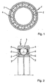
- FIG. 1 indicated that at least the inner roller bearing ring 2 of the rolling bearing 1 consists of a solid composite of two layers of different metallic materials, wherein the region of the raceway 6 for the rolling elements 4 of a steel with very high hardness and wear resistance and the core portion 7 of the rolling bearing ring 2 from a steel with high toughness is formed.
- a material for the raceway 6 of the rolling elements 4 is a powder metallurgy high-speed steel with a high content of carbide-forming Alloy elements and a high carbon content provided, while the material for the core portion 7 of the rolling bearing ring 2 made of a hot-work steel with a low content compared to the raceway material 11 carbide-forming alloying elements and low carbon content.
- both materials are bonded to one another by diffusion bonding, the material for the raceway 6 of the rolling elements 4 being formed by the high-speed steel S 10-2-5-8 PM, which contains more than 5% of the alloying components Cr, Mo, W and V and more as 0.8% carbon content, while the material for the core portion 7 of the rolling bearing ring 2 is formed by the hot work tool X40CrMoV5-1 having less than 12% alloy components Cr, Mo, W and V and less than 0.5% carbon content.
- FIG. 3 It is apparent here that first a steel cylinder 8 made of the material of the core region 7 of the rolling bearing ring 2 is inserted into a thin-walled cylindrical steel capsule 9 and then the cavity 10 between the steel cylinder 8 and the steel capsule 9 is filled with the metal powder of the raceway material 11 and compacted manually. Thereafter, with the thus prepared steel capsule 9, the sintering of the raceway material 11 and the simultaneous material connection of the same with the steel cylinder 8 by diffusion welding by means of hot isostatic pressing.
- the steel capsule 9 is a high, in FIG.
Landscapes
- Engineering & Computer Science (AREA)
- General Engineering & Computer Science (AREA)
- Mechanical Engineering (AREA)
- Manufacturing & Machinery (AREA)
- Rolling Contact Bearings (AREA)
- Medicines That Contain Protein Lipid Enzymes And Other Medicines (AREA)
Description
Die Erfindung betrifft einen Wälzlagerring nach den oberbegriffsbildenden Merkmalen des Patentanspruchs 1, der insbesondere geeignet ist für hochbeanspruchte Wälzlager in Flugzeugtriebwerken, sowie ein Verfahren zur Herstellung eines solchen Wälzlagerrings.The invention relates to a rolling bearing ring according to the preamble forming features of claim 1, which is particularly suitable for highly stressed rolling bearings in aircraft engines, and a method for producing such a rolling bearing ring.
Dem Fachmann in der Triebwerktechnik von Flugzeugen ist es allgemein bekannt, dass für die Lagerringe von hoch beanspruchten Wälzlagern, wie beispielsweise die Hauptwellenlager von Flugzeugtriebwerken, wegen der hohen Betriebstemperaturen vor allem warmfeste Lagerwerkstoffe wie M50 (80 MoCr V 42-16, 1.3551) oder auch warmfeste Einsatzstähle wie M50 NiL (13MoCrNi 42-16-14, 1.3555) eingesetzt werden. Diese Werkstoffe weisen nach der Aufkohlung und Härtung im Bereich der Laufbahn eine hohe Härte und im nicht aufgekohlten Kernbereich des Lagerrings eine hohe Zähigkeit auf. Die Zusammensetzung dieser Werkstoffe ist aber bis auf den Kohlenstoffgehalt über den gesamten Querschnitt des Lagerrings konstant. Daher sind die unterschiedlichen Anforderungen an die Laufbahnen der Lagerringe, wie hohe Überrollfestigkeit und Verschleißfestigkeit, sowie an die Kernbereiche der Lagerringe, wie hohe Zähigkeit, nur in begrenztem Umfang zu verwirklichen.The person skilled in the engine technology of aircraft, it is well known that for the bearing rings of high-stress rolling bearings, such as the main shaft bearings of aircraft engines, because of the high operating temperatures especially heat-resistant bearing materials such as M50 (80 MoCr V 42-16, 1.3551) or heat resistant case hardening steels such as M50 NiL (13MoCrNi 42-16-14, 1.3555) are used. These materials have a high hardness after carburizing and hardening in the area of the track and im not carburized core portion of the bearing ring to a high toughness. The composition of these materials, however, is constant over the entire cross section of the bearing ring except for the carbon content. Therefore, the different requirements on the raceways of the bearing rings, such as high rollover resistance and wear resistance, as well as to the core areas of the bearing rings, such as high toughness, can be realized only to a limited extent.
Eine Möglichkeit, den hohen Anforderungen an Wälzlager in Flugzeugtriebwerken noch besser gerecht zu werden, ist es daher, die Wälzlagerringe jeweils aus einem festen Verbund zweier Schichten aus verschiedenen metallischen Werkstoffen herzustellen, das heißt, den Bereich der Laufbahn für die Wälzkörper aus einem Stahl mit sehr hoher Härte und Verschleißfestigkeit und der Kernbereich des Wälzlagerrings aus einem Stahl mit hoher Zähigkeit auszubilden.One way to meet the high demands on rolling bearings in aircraft engines even better, it is therefore to produce the rolling bearing rings each consist of a solid composite of two layers of different metallic materials, that is, the range of the raceway for the rolling elements of a steel with very high hardness and wear resistance and the core portion of the rolling bearing ring of a steel with high toughness form.
Ein solcher Wälzlagerring aus einem Vebundwerkstoff ist beispielsweise aus der
Nachteilig bei diesem Wälzlagerring aus einem Verbundwerkstoff ist es, dass die beiden Ringe aus verschiedenen Werkstoffen gemeinsam gleichzeitig tangential, radial und axial durch Walzen verformt und miteinander verbunden werden. Aus der Praxis ist es jedoch bekannt, dass insbesondere das Kaltwalzen von hochwarmfesten und verschleißfesten Werkstoffen nur begrenzt durchführbar ist, da diese Werkstoffe in der Regel über ein unterschiedliches Aufweitvermögen verfügen. Dadurch wird eine dauerhafte Verbindung der beiden Ringe problematisch, so dass auch mit dem anschließenden Schrumpfen nur in Ausnahmefällen ein fester Verbund zwischen den Ringen erreicht wird. Ebenso ist eine über die Breite der Laufbahn veränderliche, an den jeweiligen Einsatzfall des Wälzlagers angepasste Dicke der Schichten beider Werkstoffe mit der beschriebenen Herstellungsweise nicht realisierbar. Da die Ringe nicht stofflich direkt miteinander verbunden sind, hat sich somit ein solcher Verbund hinsichtlich seiner Dauerfestigkeit als nicht ausreichend erwiesen, um den hohen Anforderungen an Wälzlager in Flugzeugtriebwerken gerecht zu werden. Darüber hinaus sind zur Umsetzung des Herstellungsverfahrens für einen solchen Lagerring eine Vielzahl von Fertigungsschritten und Werkzeugen sowie mehrere geteilte Werkzeugformen notwendig, durch die relativ hohe Herstellungskosten für ein mit solchen Lagerringen ausgebildetes Wälzlager entstehen.A disadvantage of this rolling bearing of a composite material is that the two rings of different materials together tangentially, radially and axially deformed by rollers and connected together. From practice, however, it is known that in particular the cold rolling of high-temperature resistant and wear-resistant materials is limited feasible is because these materials usually have a different Aufweitvermögen. As a result, a permanent connection of the two rings is problematic, so that even with the subsequent shrinking only in exceptional cases, a solid bond between the rings is achieved. Likewise, over the width of the career variable, adapted to the particular application of the rolling bearing thickness of the layers of both materials with the described production method is not feasible. Since the rings are not materially connected directly to each other, such a composite has thus not proven sufficient in terms of fatigue strength to meet the high demands on roller bearings in aircraft engines. In addition, to implement the manufacturing process for such a bearing ring a variety of manufacturing steps and tools and several shared tool shapes necessary to arise through the relatively high production costs for such a bearing rings designed rolling bearing.
Eine weitere Möglichkeit zur Herstellung eines Wälzlagerrings aus einem Verbundwerkstoff wird darüber hinaus durch die
Bei einem nach diesem Verfahren hergestellten Wälzlagerring sind die beiden Ringe des Werkstoffverbundes zwar durch den Sintervorgang auch stofflich miteinander verbunden, jedoch ist auch hier durch die Verwendung eines gestanzten Blechteils für den Laufbahnbereich die Schichtdicke dieser Laufbahn weitgehend konstant und kann nicht in wünschenswerter Weise in ihrer Stärke über die Breite der Laufbahn variiert werden. Ebenso ist auch bei diesem Werkstoffverbund das abschließende gemeinsame Walzen oder Schmieden des warmfesten und des verschleißfesten Werkstoffes für den Kernbereich und für den Laufbahnbereich fertigungstechnisch nur sehr aufwändig umsetzbar. Darüber hinaus hat sich der Aufwand für die Herstellung eines solchen Werkstoffverbundes in der Praxis als unwirtschaftlich erwiesen, insbesondere deshalb, da für jeden einzelnen Lagerring eine gesonderte Form zum Verdichten und zum Sintern des Metallpulvers zur Verfügung stehen muss sowie durch den aufwändigen Verdichtungs- und Abkühlungsprozess des Sintermetalls.In a rolling bearing ring produced by this method, the two rings of the composite materials are indeed material by the sintering process connected to each other, but here, too, by the use of a stamped sheet metal part for the track area, the layer thickness of this track is largely constant and can not be varied in their strength in a desirable manner across the width of the track. Likewise, in the case of this material composite, the final joint rolling or forging of the heat-resistant and wear-resistant material for the core region and for the raceway region can only be implemented with great difficulty in terms of manufacturing technology. In addition, the effort for the production of such a composite material has proven in practice to be uneconomical, especially because for each bearing ring a separate mold for compacting and sintering of the metal powder must be available and by the complex compression and cooling process of the sintered metal.
Ausgehend von den dargelegten Nachteilen der Lösungen des bekannten Standes der Technik liegt der Erfindung deshalb die Aufgabe zu Grunde, einen Wälzlagerring, insbesondere für hochbeanspruchte Wälzlager in Flugzeugtriebwerken, zu konzipieren, der aus einem dauerfesten Verbund zweier Schichten aus einem Stahl mit sehr hoher Härte und Verschleißfestigkeit für den Bereich seiner Laufbahn und aus einem Stahl mit hoher Zähigkeit für seinen Kernbereich besteht und dabei mit einer weitestgehend variablen Schichtstärke der Laufbahn über die Laufbahnbreite ausgebildet ist und welcher sich durch eine kostengünstige Herstellung auszeichnet.Based on the stated disadvantages of the solutions of the known prior art, the invention is therefore based on the object to design a rolling bearing ring, in particular for highly stressed rolling bearings in aircraft engines, consisting of a durable composite of two layers of a steel with very high hardness and wear resistance consists of a high-strength steel for its core area and is formed with a largely variable layer thickness of the career over the raceway width and which is characterized by a cost-effective production.
Erfindungsgemäß wird diese Aufgabe bei einem Wälzlagerring nach dem Oberbegriff des Anspruchs 1 derart gelöst, dass als Werkstoff für die Laufbahn der Wälzkörper ein pulvermetallurgischer Schnellarbeitsstahl mit hohem Gehalt an karbidbildenden Legierungselementen und einem hohen Kohlenstoffgehalt vorgesehen ist, während der Werkstoff für den Kernbereich des Wälzlagerrings aus einem Warmarbeitsstahl mit im Vergleich zum Laufbahnwerkstoff niedrigem Gehalt an karbidbildenden Legierungselementen und niedrigem Kohlenstoffgehalt besteht, und dass beide Werkstoffe durch Diffusionsschweißen stoffschlüssig miteinander verbunden sind.According to the invention this object is achieved in a rolling bearing ring according to the preamble of claim 1 such that as a material for the raceway of the rolling elements a powder metallurgy high-speed steel with high content is provided on carbide-forming alloying elements and a high carbon content, while the material for the core portion of the rolling bearing ring made of a hot work steel with a low carbide-forming alloy content and low carbon content compared to the raceway material, and that both materials are bonded together by diffusion bonding.
Der Erfindung liegt somit die Erkenntnis zu Grunde, dass durch Diffusionsschweißen verschleißfeste Werkstoffverbunde mit hoher Warmhärte hergestellt werden können, die den unterschiedlichen Anforderungen an die Laufbahn und den Kernbereich eines hochbelasteten Wälzlagers nahezu optimal gerecht werden. Ein pulvermetallurgischer Schnellarbeitsstahl als Werkstoff für die Laufbahn der Wälzkörper weist nach geeigneter Wärmebehandlung durch den hohen Gehalt an Hartphasen (Karbide) eine im Vergleich zum aufgekohlten Einsatzstahl M50 NiL wesentlich bessere Verschleißfestigkeit auf. Wegen der sehr feinen homogenen Mikrostruktur ist dabei trotz des hohen Karbidgehaltes die Überrollfestigkeit des Laufbahnbereiches sehr hoch. Auch eine nachträgliche Verdichtung des Verbundes ist nicht notwendig, da durch die simultane Einwirkung von hoher Temperatur und hohem Druck Werkstoffe ohne Restporösität erzeugt werden. Der Warmarbeitsstahl für den Kernbereich des Wälzlagerrings lässt sich darüber hinaus bezüglich seiner Zusammensetzung abweichend vom Laufbahnwerkstoff auf hohe Zähigkeit abstimmen, muss aber bezüglich seines Härteverhaltens an den Härteprozess für den Laufbahnwerkstoff angepasst werden.The invention is therefore based on the finding that wear-resistant composite materials can be produced with high hot hardness by diffusion welding, which almost perfectly meet the different requirements for the career and the core area of a highly loaded roller bearing. A powder-metallurgical high-speed steel as a material for the raceway of the rolling elements has, after suitable heat treatment by the high content of hard phases (carbides) a much better wear resistance compared to the carburized case steel M50 NiL. Because of the very fine homogeneous microstructure, the rollover resistance of the raceway area is very high despite the high carbide content. A subsequent compression of the composite is not necessary because materials are produced without residual porosity by the simultaneous action of high temperature and high pressure. The hot working steel for the core region of the rolling bearing ring can also be tuned in terms of its composition deviating from the raceway material to high toughness, but must be adjusted in terms of its hardness behavior of the hardening process for the raceway material.
Bevorzugte Ausgestaltungen und Weiterbildungen des erfindungsgemäß ausgebildeten Wälzlagerrings werden in den Unteransprüchen beschrieben.Preferred embodiments and further developments of the inventively embodied rolling bearing ring are described in the subclaims.
Danach ist es gemäß der Ansprüche 2 und 3 vorgesehen, dass der Werkstoff für die Laufbahn der Wälzkörper bevorzugt durch den Schnellarbeitsstahl S 10-2-5-8 PM gebildet wird, der mehrr als 5 % Legierungsbestandteile Cr, Mo, W und V aufweist und dessen Kohlenstoffgehalt größer als 0,8 % ist, während der Werkstoff für den Kernbereich des Wälzlagerrings bevorzugt durch den Warmarbeitsstahl X40CrMoV5-1 gebildet wird, der weniger als 12 % Legierungsbestandteile Cr, Mo, W und V aufweist und dessen Kohlenstoffgehalt kleiner als 0,5 % ist.Thereafter, it is provided according to
Die gestellte Aufgabe wird darüber hinaus auch durch ein erfindungsgemäßes Verfahren zur Herstellung eines Wälzlagerrings mit den beschriebenen Merkmalen gelöst, welches nachfolgend am Beispiel der Herstellung eines Wälzlagerinnenrings bzw. eines Wälzlageraußenrings beschrieben wird:The object is also achieved by an inventive method for producing a rolling bearing ring having the described features, which is described below using the example of the production of a roller bearing inner ring or a roller bearing outer ring:
Für die Herstellung von Wälzlagerinnenringen wird als Ausgangsmaterial für den Kernbereich bevorzugt ein stangenförmiger Stahlzylinder aus dem Warmarbeitsstahl X40CrMoV5-1 verwendet, während das Ausgangsmaterial für die Herstellung von Wälzlageraußenringen bevorzugt durch ein dickwandiges Stahlrohr aus dem gleichen Material gebildet wird. Als Hilfswerkzeug wird darüber hinaus eine dünnwandige zylindrische Stahlkapsel von der Höhe des Stahlzylinders bzw. des Stahlrohres benötigt, in die im Fall der Herstellung von Wälzlagerinnenringen der Stahlzylinder zentrisch bzw. im Fall der Herstellung von Wälzlageraußenringen das Stahlrohr konzentrisch an der Innenseite der Stahlkapsel anliegend eingesetzt wird. Anschließend wird der Raum zwischen dem Stahlzylinder und der Innenseite der Stahlkapsel bzw. der Hohlraum des Stahlrohres mit dem in Pulverform vorliegenden Schnellarbeitsstahl S 10-2-5-8 PM des Laufbahnwerkstoffs befüllt und manuell verdichtet.For the production of rolling bearing inner rings, a rod-shaped steel cylinder of the hot-working steel X40CrMoV5-1 is preferably used as starting material for the core region, while the starting material for the production of rolling bearing outer rings is preferably formed by a thick-walled steel tube made of the same material. In addition, a thin-walled cylindrical steel capsule of the height of the steel cylinder or of the steel tube is required as an auxiliary tool, in which case the steel tube is used concentrically on the inner side of the steel capsule in the case of the production of rolling bearing inner rings of the steel cylinder centric or in the case of manufacturing Wälzlageraußenringen , Subsequently, the space between the steel cylinder and the inside of the steel capsule or the cavity of the steel pipe is filled with the present in powder form high-speed steel S 10-2-5-8 PM of the career material and compacted manually.
Die so vorbereitete Stahlkapsel wird dann an ihrem offenen Ende verschlossen und gegebenenfalls evakuiert und in einem geeigneten Ofen gleichzeitig einem Druck von ca. 1000 bar und einer Temperatur von 1000°C bis 1200°C ausgesetzt. Durch diesen als Diffusionsschweißen mittels heißtisostatischem Pressen bezeichneten Vorgang erfolgt das Sintern des Metallpulvers des Laufbahnwerkstoffs zu einem dichten Material sowie gleichzeitig eine stofflich Verbindung des gesinterten Metalls mit dem Stahlzylinder oder dem Stahlrohr des Kernbereichs.The thus prepared steel capsule is then closed at its open end and optionally evacuated and simultaneously exposed in a suitable oven to a pressure of about 1000 bar and a temperature of 1000 ° C to 1200 ° C. By this process, called diffusion welding by means of hot isostatic pressing, the sintering of the metal powder of the raceway material into a dense material and, at the same time, a material connection of the sintered metal with the steel cylinder or the steel tube of the core region takes place.
Nach der Abkühlung des entstandenen Verbundrohlings auf Raumtemperatur und der Entfernung der Stahlkapsel wird der Verbundrohling dann auf einem Drehautomaten mit einer zentrischen Bohrung versehen und gleichzeitig in einzelne Verbundringe zerspant. Bei der Herstellung von Wälzlagerinnenringen wird die Bohrung dabei in den Werkstoff des Kernbereichs eingearbeitet, während diese bei der Herstellung von Wälzlageraußenringen in den Werkstoff der Laufbahn eingearbeitet wird.After the cooling of the resulting composite blank to room temperature and the removal of the steel capsule, the composite blank is then provided on a lathe with a central bore and simultaneously machined into individual composite rings. In the production of rolling bearing inner rings, the bore is thereby incorporated into the material of the core region, while this is incorporated in the production of rolling bearing outer rings in the material of the raceway.
Anschließend wird in den Laufbahnwerkstoff des durch die Zerspanung entstandenen Verbundrings durch Walzen zwischen zwei Profilwalzen eine Laufbahnrinne eingearbeitet, wobei das Einwalzen dieser Laufbahnrinne die Aufgabe hat, im gesamten Bereich der späteren Laufbahn bzw. über deren gesamte Breite eine optimale Schichtstärke des Laufbahnwerkstoffes zu schaffen.Subsequently, a raceway groove is incorporated into the raceway material of the composite ring produced by the machining by rolling between two profile rollers, the rolling in of this raceway channel having the task of creating an optimal layer thickness of the raceway material throughout the entire range of the later raceway or over its entire width.
Danach erfolgt dann die Herstellung der annähernden Außenkontur des Wälzlagerringes durch Zerspanen des Verbundrings mit abschließendem Härten und Schleifen auf endgültige Lagerringabmessungen. Das Härten des Wälzlagerrings erfolgt dabei bevorzugt bei einer Temperatur zwischen 1000°C und 1200°C, so dass der Laufbahnwerkstoff eine Härte von mindestens 750 HV und der Kernwerkstoff eine Härte von mindestens 500 HV aufweist.Thereafter, then the production of the approximate outer contour of the rolling bearing ring by machining the composite ring with final hardening and grinding takes place on final bearing ring dimensions. The hardening of the rolling bearing ring is preferably carried out at a temperature between 1000 ° C and 1200 ° C, so that the raceway material has a hardness of at least 750 HV and the core material has a hardness of at least 500 HV.
Der nach diesem Verfahren hergestellte, erfindungsgemäß ausgebildete Wälzlagerring weist somit gegenüber den aus dem Stand der Technik bekannten Wälzlagerringen den Vorteil auf, dass er aus einem dauerfesten Verbund zweier Schichten aus einem Stahl mit sehr hoher Härte und Verschleißfestigkeit für den Bereich seiner Laufbahn und aus einem Stahl mit hoher Zähigkeit für seinen Kernbereich besteht und durch einen gezielten Profilwalzvorgang mit einer weitestgehend variablen Schichtstärke der Laufbahn über die Laufbahnbreite ausgebildet werden kann. Dabei wird durch das Diffusionsschweißen mittels heißisostatischem Pressen nicht nur der pulvermetallurgischer Schnellarbeitsstahl für den Laufbahnbereich gesintert sondern gleichzeitig eine stoffliche Verbindung zum Werkstoff des Kernbereichs erreicht, durch die der hergestellte Wälzlagerring auf jeden Fall den hohen Anforderungen an Wälzlager in Flugzeugtriebwerken gerecht wird. Durch relativ kostengünstige Ausgangsmaterialien, einfache Hilfsvorrichtungen und mäßigen Fertigungsaufwand zeichnet sich der erfin-dungsgemäß ausgebildete Wälzlagerring trotz einzelner spanabhebender Fertigungsschritte insgesamt auch durch eine kostengünstige Herstellung aus.The rolling bearing ring produced according to the invention and thus designed according to the invention thus has the advantage over the rolling bearing rings known from the prior art that it consists of a durable composite of two layers of a steel with very high hardness and wear resistance for the region of its raceway and of a steel With high toughness for its core area and can be formed by a targeted profile rolling process with a largely variable layer thickness of the track over the track width. In this case, not only the powder-metallurgical high-speed steel for the raceway area is sintered by the diffusion welding by means of hot isostatic pressing but also achieved a material connection to the material of the core region, through which the rolling bearing ring produced In any case, meet the high demands on bearings in aircraft engines. Due to relatively inexpensive starting materials, simple auxiliary devices and moderate production costs, the inventively formed according to the rolling bearing ring is characterized in spite of individual machining steps in total by a cost-effective production.
Eine bevorzugte Ausführungsform eines erfindungsgemäß ausgebildeten Wälzlagerrings sowie des Verfahrens zu dessen Herstellung wird nachfolgend unter Bezugnahme auf die beigefügten Zeichnungen näher erläutert. Dabei zeigen:
- Figur 1
- einen Längsschnitt durch ein als Dreipunkt-Kugellager ausgebildetes Hauptwellenlager eines Flugzeugtriebwerkes;
Figur 2- eine vergrößerte Darstellung eines Querschnittes durch das Dreipunkt-Kugellager nach
Figur 1 ; Figur 3- eine schematische Darstellung der Verfahrensschritte a) bis c) zur Herstellung eines erfindungsgemäß ausgebildeten inneren Wälzlagerrings für das Dreipunkt-Kugellager nach
Figur 1 ; Figur 4- eine schematische Darstellung des Verfahrensschritts d) zur Herstellung eines erfindungsgemäß ausgebildeten inneren Wälzlagerrings für das Dreipunkt-Kugellager nach
Figur 1 ; Figur 5- eine schematische Darstellung des Verfahrensschritts e) zur Herstellung eines erfindungsgemäß ausgebildeten inneren Wälzlagerrings für das Dreipunkt-Kugellager nach
Figur 1 ; Figur 6- eine schematische Darstellung des Verfahrensschritts f) zur Herstellung eines erfindungsgemäß ausgebildeten inneren Wälziagerrings für das Dreipunkt-Kugellager nach
Figur 1 ; Figur 7- eine vergrößerte Darstellung eines Querschnittes durch einen fertig bearbeiteten, erfindungsgemäß ausgebildeten inneren Wälzlagerring für das Dreipunkt-Kugellager nach
Figur 1 ; Figur 8- eine graphische Darstellung des Härteverlaufs durch einen erfindungsgemäß ausgebildeten inneren Wälzlagerring für das Dreipunkt-Kugellager nach
Figur 1 .
- FIG. 1
- a longitudinal section through a designed as a three-point ball bearing main shaft bearing of an aircraft engine;
- FIG. 2
- an enlarged view of a cross section through the three-point ball bearing
FIG. 1 ; - FIG. 3
- a schematic representation of the process steps a) to c) for producing an inventively designed inner rolling bearing ring for the three-point ball bearing according to
FIG. 1 ; - FIG. 4
- a schematic representation of the process step d) for producing an inventively designed inner rolling bearing ring for the three-point ball bearing according to
FIG. 1 ; - FIG. 5
- a schematic representation of the process step e) for producing an inventively designed inner rolling bearing ring for the three-point ball bearing according to
FIG. 1 ; - FIG. 6
- a schematic representation of the process step f) for producing an inventively designed inner Wälziagerrings for the three-point ball bearing according to
FIG. 1 ; - FIG. 7
- an enlarged view of a cross section through a finished, inventively designed inner rolling bearing ring for the three-point ball bearing
FIG. 1 ; - FIG. 8
- a graphic representation of the hardness curve by an inventively designed inner roller bearing ring for the three-point ball bearing after
FIG. 1 ,
Aus den
Um den hohen Anforderungen an einen solchen Wälzlagerring 2 hinsichtlich Temperaturbeständigkeit, Verschleißfestigkeit und Zähigkeit gerecht zu werden, ist dabei erfindungsgemäß als Werkstoff für die Laufbahn 6 der Wälzkörper 4 ein pulvermetallurgischer Schnellarbeitsstahl mit hohem Gehalt an karbidbildenden Legierungselementen und einem hohen Kohlenstoffgehalt vorgesehen, während der Werkstoff für den Kernbereich 7 des Wälzlagerrings 2 aus einem Warmarbeitsstahl mit im Vergleich zum Laufbahnwerkstoff 11 niedrigem Gehalt an karbidbildenden Legierungselementen und niedrigem Kohlenstoffgehalt besteht. Beide Werkstoffe sind erfindungsgemäß durch Diffusionsschweißen stoffschlüssig miteinander verbunden, wobei der Werkstoff für die Laufbahn 6 der Wälzkörper 4 durch den Schnellarbeitsstahl S 10-2-5-8 PM gebildet wird, der mehr als 5 % Legierungsbestandteile Cr, Mo, W und V und mehr als 0,8 % Kohlenstoffgehalt aufweist, während der Werkstoff für den Kernbereich 7 des Wälzlagerrings 2 durch den Warmarbeitsstahl X40CrMoV5-1 gebildet wird, der weniger als 12 % Legierungsbestandteile Cr, Mo, W und V und weniger als 0,5 % Kohlenstoffgehalt aufweist.In order to meet the high demands on such a
Anhand der
Aus
Nach der Abkühlung des entstandenen Verbundrohlings erfolgt dann auf einem Drehautomaten das Einarbeiten einer zentrischen Bohrung 12 in den Werkstoff des Kernbereichs 7 und die Zerspanung des Verbundrohlings in einzelne Verbundringe 13, von denen ein Verbundring 13 beispielhaft in
Abschließend erfolgt dann die Herstellung der annähernden Außenkontur des in
- 11
- Wälzlagerroller bearing
- 22
- innerer Wälzlagerringinner rolling bearing ring
- 33
- äußerer Wälzlagerringouter rolling bearing ring
- 44
- Wälzkörperrolling elements
- 55
- Lagerkäfigbearing cage
- 66
- Laufbahncareer
- 77
- Kernbereichcore area
- 88th
- Stahlzylindersteel cylinder
- 99
- Stahlkapselsteel capsule
- 1010
- Hohlraumcavity
- 1111
- LaufbahnwerkstoffRaceway material
- 1212
- Bohrungdrilling
- 1313
- Verbundringcomposite ring
- 1414
- Walzeroller
- 1515
- Walzeroller
- 1616
- LaufbahnrinneRaceway groove
Claims (6)
- Rolling bearing ring, in particular for highly-loaded rolling bearings in aircraft power plants, which rolling bearing ring is composed of a fixed composite of two layers composed of different metallic materials, with the region of the raceways (6) for the rolling bodies (4) being composed of a steel with a very high level of hardness and wear resistance, and the core region (7) of the rolling bearing ring (2) being composed of a steel with a high level of ductility, characterized in that a powder metallurgical high-speed steel with a high content of carbide-forming alloy elements and a high carbon content is provided as a material for the raceway (6) of the rolling bodies (4), while the material for the core region (7) of the rolling bearing ring (2) is composed of a hot-work steel with a lower content of carbide-forming alloy elements, and a lower carbon content, than the raceway material (11), and in that the two materials are cohesively connected to one another by means of diffusion welding.
- Rolling bearing ring according to Claim 1,
characterized in that the material for the raceway (6) of the rolling bodies (4) is preferably formed by the high-speed steel S 10-2-5-8 PM which has more than 5% alloy constituents Cr, Mo, W and V and whose carbon content is greater than 0.8%. - Rolling bearing ring according to Claim 1,
characterized in that the material for the core region (7) of the rolling bearing ring (2) is preferably formed by the hot-work steel X40CrMoV5-1 which has less than 12% alloy constituents Cr, Mo, W and V and whose carbon content is less than 0.5%. - Method for producing a rolling bearing ring having the features of Claim 1, characterized by the following method steps:a) centrally inserting a steel cylinder (8) or concentrically inserting a steel tube composed of the material of the core region (7) of the rolling bearing ring (2) into a thin-walled cylindrical steel capsule (8);b) filling the cavity (10) between the steel cylinder (8) and the steel capsule (9) or the cavity of the steel tube with the metal powder of the raceway material (11) and compressing said metal powder;c) sintering the raceway material (11) and simultaneously connecting the latter to the steel cylinder (8) or to the steel tube of the core region (7) by means of diffusion welding by means of hot isostatic pressing;d) machining a central bore (12) into the material of the core region (7) or into the raceway material and cutting the composite blank into individual composite rings (13);e) machining a raceway groove (16) into the raceway material while simultaneously deepening the layer thickness of the latter by rolling the composite ring (13) between two profile rollers (14, 15);f) producing the approximate outer contour of the rolling bearing ring (2) by cutting the composite ring (13) with subsequent hardening and grinding to the final bearing ring dimensions.
- Method for producing a rolling bearing ring according to Claim 4, characterized in that the sintering and simultaneous diffusion welding of the two materials for the raceway (6) and for the core region (7) of the rolling bearing ring (2) by means of hot isostatic pressing preferably takes place at a pressure of approximately 1000 bar and at a temperature of 1000°C to 1200°C.
- Method for producing a rolling bearing ring according to Claim 4, characterized in that the subsequent hardening of the rolling bearing ring (2) preferably takes place at a temperature between 1000°C and 1200°C, so that the raceway material (11) has a hardness of at least 750 HV and the material of the core region (7) has a hardness of at least 500 HV.
Applications Claiming Priority (2)
| Application Number | Priority Date | Filing Date | Title |
|---|---|---|---|
| DE102005022730A DE102005022730A1 (en) | 2005-05-18 | 2005-05-18 | Rolling bearing ring, in particular for highly stressed roller bearings in aircraft engines, and method for its production |
| PCT/DE2006/000784 WO2006122518A2 (en) | 2005-05-18 | 2006-05-06 | Antifriction bearing race, particularly for highly stressed antifriction bearings in aircraft power units and methods for the production thereof |
Publications (2)
| Publication Number | Publication Date |
|---|---|
| EP1882109A2 EP1882109A2 (en) | 2008-01-30 |
| EP1882109B1 true EP1882109B1 (en) | 2009-04-15 |
Family
ID=37037013
Family Applications (1)
| Application Number | Title | Priority Date | Filing Date |
|---|---|---|---|
| EP06722842A Not-in-force EP1882109B1 (en) | 2005-05-18 | 2006-05-06 | Antifriction bearing race, particularly for highly stressed antifriction bearings in aircraft power units and methods for the production thereof |
Country Status (6)
| Country | Link |
|---|---|
| US (1) | US7857518B2 (en) |
| EP (1) | EP1882109B1 (en) |
| JP (1) | JP2008540982A (en) |
| CA (1) | CA2615882C (en) |
| DE (2) | DE102005022730A1 (en) |
| WO (1) | WO2006122518A2 (en) |
Cited By (1)
| Publication number | Priority date | Publication date | Assignee | Title |
|---|---|---|---|---|
| US9555501B2 (en) | 2013-04-09 | 2017-01-31 | Aktiebolaget Skf | Process for obtaining a mechanical component |
Families Citing this family (14)
| Publication number | Priority date | Publication date | Assignee | Title |
|---|---|---|---|---|
| JP5429730B2 (en) * | 2007-11-30 | 2014-02-26 | Ntn株式会社 | Manufacturing method of machine parts and machine parts |
| US20110311362A1 (en) * | 2008-12-04 | 2011-12-22 | Jochen Corts | Compound Steel Bearings and Methods of Manufacturing |
| JP5310338B2 (en) * | 2009-07-15 | 2013-10-09 | 株式会社ジェイテクト | Rolling bearing mounting structure |
| DE102010014960A1 (en) | 2010-04-14 | 2011-10-20 | Schaeffler Technologies Gmbh & Co. Kg | Rolling elements, in particular in machine tool spindles and method for its production |
| DE102010019587B4 (en) | 2010-05-05 | 2022-02-03 | Schaeffler Technologies AG & Co. KG | roller bearing |
| WO2013088201A1 (en) * | 2011-12-14 | 2013-06-20 | AMSC Austria GmbH | Bearing, wind energy converter and method of manufacturing a bearing |
| FR3000149B1 (en) * | 2012-12-21 | 2015-01-16 | Skf Aerospace France | METHOD FOR MANUFACTURING A BALL BEARING, IN PARTICULAR FOR A BUTTERFLY VALVE IN AERONAUTICAL ENVIRONMENT |
| DE102013100580A1 (en) * | 2013-01-21 | 2014-07-24 | Deutsche Edelstahlwerke Gmbh | A method of producing a metallic composite flat product, flat steel product and use of a flat steel product |
| CN105264245B (en) * | 2013-04-09 | 2018-07-06 | 斯凯孚公司 | Parts of bearings and its manufacturing method |
| SE537381C2 (en) * | 2013-04-09 | 2015-04-14 | Skf Ab | Bearing component part, bearing component and process for manufacturing a bearing component |
| SE536978C2 (en) * | 2013-04-12 | 2014-11-18 | Skf Ab | Bearing component part and a method of forming a bearing component |
| DE102016114895A1 (en) * | 2016-08-11 | 2018-02-15 | Thyssenkrupp Ag | Method for hardening a rolling body raceway of a rolling bearing ring and rolling bearing ring |
| CN108916242A (en) * | 2017-01-04 | 2018-11-30 | 宁波高新区起兴机电有限公司 | A kind of novel high speed motor bearing of washing machine |
| DE102019218794A1 (en) * | 2019-12-03 | 2021-06-10 | Thyssenkrupp Ag | Process for increasing the load-bearing capacity and rolling device for hard rolling a surface-hardened roller bearing raceway |
Family Cites Families (21)
| Publication number | Priority date | Publication date | Assignee | Title |
|---|---|---|---|---|
| DE200923C (en) * | 1906-08-03 | |||
| US2845311A (en) * | 1954-04-26 | 1958-07-29 | Gen Motors Corp | Antifriction bearing |
| US3409966A (en) * | 1966-04-22 | 1968-11-12 | Bethlehem Steel Corp | Method of producing bi-metal bearing sleeve |
| FR1561481A (en) * | 1968-02-16 | 1969-03-28 | ||
| US3665585A (en) * | 1970-12-04 | 1972-05-30 | Federal Mogul Corp | Composite heavy-duty mechanism element and method of making the same |
| US3791706A (en) * | 1971-06-09 | 1974-02-12 | Formmet Corp | Forged ring structure of multiple cast metals |
| US3770332A (en) * | 1971-06-14 | 1973-11-06 | Federal Mogul Corp | Composite heavy-duty bushing and method of making the same |
| US3762881A (en) * | 1971-06-14 | 1973-10-02 | Federal Mogul Corp | Composite high strength machine element and method of making the same |
| US3772935A (en) * | 1972-03-20 | 1973-11-20 | W Dunn | Composite heavy-duty sintered powdered machine element |
| FR2372348A1 (en) * | 1976-10-26 | 1978-06-23 | Roulements Soc Nouvelle | COMPOSITE RING FOR BEARING AND ITS MANUFACTURING PROCESS |
| FR2436642A1 (en) * | 1978-09-25 | 1980-04-18 | Roulements Soc Nouvelle | PROCESS FOR MANUFACTURING A COMPOSITE BEARING RING |
| JPS56163821A (en) | 1980-05-19 | 1981-12-16 | Ntn Toyo Bearing Co Ltd | Manufacture of annular material |
| JPS58137621A (en) * | 1982-02-10 | 1983-08-16 | Fuji Seikou Kk | Bearing |
| JPS58163821A (en) * | 1982-03-19 | 1983-09-28 | Fuji Seikou Kk | Bearing |
| JPS58178804A (en) * | 1982-04-14 | 1983-10-19 | Hitachi Ltd | steam turbine rotor shaft |
| DE3919199A1 (en) * | 1989-06-13 | 1990-12-20 | Skf Gmbh | METHOD FOR THE PRODUCTION OF ROTOR BEARING ELEMENTS |
| JPH0469406A (en) * | 1990-07-05 | 1992-03-04 | Ube Ind Ltd | Ball bearing |
| JPH06341443A (en) * | 1993-06-03 | 1994-12-13 | Nippon Thompson Co Ltd | Non-magnetic raceway track body and manufacture thereof |
| DE59609657D1 (en) * | 1996-06-17 | 2002-10-17 | Hau Hanspeter | PM hot work steel and process for its production |
| US20030019106A1 (en) * | 2001-04-22 | 2003-01-30 | Diamicron, Inc. | Methods for making bearings, races and components thereof having diamond and other superhard surfaces |
| DE10343782A1 (en) * | 2003-09-22 | 2005-04-14 | Mtu Aero Engines Gmbh | Process for the production of components |
-
2005
- 2005-05-18 DE DE102005022730A patent/DE102005022730A1/en not_active Withdrawn
-
2006
- 2006-05-06 DE DE502006003454T patent/DE502006003454D1/en active Active
- 2006-05-06 EP EP06722842A patent/EP1882109B1/en not_active Not-in-force
- 2006-05-06 JP JP2008515037A patent/JP2008540982A/en active Pending
- 2006-05-06 WO PCT/DE2006/000784 patent/WO2006122518A2/en not_active Ceased
- 2006-05-06 CA CA2615882A patent/CA2615882C/en not_active Expired - Fee Related
- 2006-05-06 US US11/914,616 patent/US7857518B2/en not_active Expired - Fee Related
Cited By (1)
| Publication number | Priority date | Publication date | Assignee | Title |
|---|---|---|---|---|
| US9555501B2 (en) | 2013-04-09 | 2017-01-31 | Aktiebolaget Skf | Process for obtaining a mechanical component |
Also Published As
| Publication number | Publication date |
|---|---|
| US7857518B2 (en) | 2010-12-28 |
| WO2006122518A3 (en) | 2007-01-04 |
| WO2006122518A2 (en) | 2006-11-23 |
| US20080212911A1 (en) | 2008-09-04 |
| CA2615882A1 (en) | 2006-11-23 |
| JP2008540982A (en) | 2008-11-20 |
| DE502006003454D1 (en) | 2009-05-28 |
| DE102005022730A1 (en) | 2006-11-23 |
| EP1882109A2 (en) | 2008-01-30 |
| CA2615882C (en) | 2014-02-25 |
Similar Documents
| Publication | Publication Date | Title |
|---|---|---|
| DE19630115C2 (en) | Method of manufacturing a bevel gear and combined press device | |
| EP1882109B1 (en) | Antifriction bearing race, particularly for highly stressed antifriction bearings in aircraft power units and methods for the production thereof | |
| EP1276915A1 (en) | Rolling bearing component | |
| DE2310536A1 (en) | PROCESS FOR MANUFACTURING COMPOSITE METAL OBJECTS | |
| DE2352578B2 (en) | Sintered metal rolling bearing ring and process for its manufacture | |
| EP3428300B1 (en) | Roller for a grinding or/and pressing device, in particular compression roller for a press for the production of pellets, and method of manufacturing the roller | |
| DE112013001748T5 (en) | Sintered component, gear for starter, and production method thereof | |
| EP4160032B1 (en) | Method for manufacturing rolling bearing element | |
| DE112007003622B4 (en) | Method of obtaining a gear with varying case hardness depth | |
| EP2725208B1 (en) | Multiple cams | |
| DE102005019482A1 (en) | Tapered roller bearing in particular for area with low requirements at stability, comprising hollow space formed by inner as well as by outer ring | |
| EP2024654A2 (en) | Rolling bearing component, and method for the production thereof | |
| AT512939A4 (en) | Process for making a composite roll and composite roll made therewith | |
| EP2364800A1 (en) | Hot isostatic pressed composite body, method for its manufacture and application | |
| DE102016103752A1 (en) | Process for producing a brass or bronze composite component by means of sintered fit | |
| DE112014001906B4 (en) | Bearing part and method of manufacturing a bearing part | |
| EP1778991B1 (en) | Anti-friction bearing comprising at least one precision deep-drawn component with a running or guide surface for rolling bodies and method for producing a component of this type | |
| DE4307560A1 (en) | Method for the powder-metallurgical production of a machine part subject in certain areas to different types of loading | |
| DE102012203110A1 (en) | Method for producing a bearing component | |
| EP1753887B1 (en) | Heavy-duty engine component | |
| WO2009143829A2 (en) | Method for producing a corrosion-resistant roller bearing | |
| DE112005002568T5 (en) | Sintered alloys for cam lobes and other high wear items | |
| DE1179720B (en) | Process for the powder metallurgical production of the components of rolling bearings that absorb the operational loads | |
| WO2003012262A1 (en) | Method for producing cams and camshafts | |
| DE112020001888T5 (en) | Diffusion-variable carburizing process |
Legal Events
| Date | Code | Title | Description |
|---|---|---|---|
| PUAI | Public reference made under article 153(3) epc to a published international application that has entered the european phase |
Free format text: ORIGINAL CODE: 0009012 |
|
| 17P | Request for examination filed |
Effective date: 20071031 |
|
| AK | Designated contracting states |
Kind code of ref document: A2 Designated state(s): DE FR GB IT SE |
|
| RBV | Designated contracting states (corrected) |
Designated state(s): DE FR GB IT SE |
|
| DAX | Request for extension of the european patent (deleted) | ||
| GRAP | Despatch of communication of intention to grant a patent |
Free format text: ORIGINAL CODE: EPIDOSNIGR1 |
|
| GRAP | Despatch of communication of intention to grant a patent |
Free format text: ORIGINAL CODE: EPIDOSNIGR1 |
|
| GRAS | Grant fee paid |
Free format text: ORIGINAL CODE: EPIDOSNIGR3 |
|
| GRAA | (expected) grant |
Free format text: ORIGINAL CODE: 0009210 |
|
| AK | Designated contracting states |
Kind code of ref document: B1 Designated state(s): DE FR GB IT SE |
|
| REG | Reference to a national code |
Ref country code: GB Ref legal event code: FG4D Free format text: NOT ENGLISH |
|
| REF | Corresponds to: |
Ref document number: 502006003454 Country of ref document: DE Date of ref document: 20090528 Kind code of ref document: P |
|
| REG | Reference to a national code |
Ref country code: SE Ref legal event code: TRGR |
|
| PLBE | No opposition filed within time limit |
Free format text: ORIGINAL CODE: 0009261 |
|
| STAA | Information on the status of an ep patent application or granted ep patent |
Free format text: STATUS: NO OPPOSITION FILED WITHIN TIME LIMIT |
|
| 26N | No opposition filed |
Effective date: 20100118 |
|
| REG | Reference to a national code |
Ref country code: GB Ref legal event code: 732E Free format text: REGISTERED BETWEEN 20110407 AND 20110413 |
|
| REG | Reference to a national code |
Ref country code: FR Ref legal event code: PLFP Year of fee payment: 11 |
|
| REG | Reference to a national code |
Ref country code: FR Ref legal event code: PLFP Year of fee payment: 12 |
|
| PGFP | Annual fee paid to national office [announced via postgrant information from national office to epo] |
Ref country code: DE Payment date: 20170731 Year of fee payment: 12 |
|
| REG | Reference to a national code |
Ref country code: FR Ref legal event code: PLFP Year of fee payment: 13 |
|
| PGFP | Annual fee paid to national office [announced via postgrant information from national office to epo] |
Ref country code: IT Payment date: 20180524 Year of fee payment: 13 Ref country code: FR Payment date: 20180525 Year of fee payment: 13 |
|
| PGFP | Annual fee paid to national office [announced via postgrant information from national office to epo] |
Ref country code: SE Payment date: 20180524 Year of fee payment: 13 |
|
| PGFP | Annual fee paid to national office [announced via postgrant information from national office to epo] |
Ref country code: GB Payment date: 20180530 Year of fee payment: 13 |
|
| REG | Reference to a national code |
Ref country code: DE Ref legal event code: R119 Ref document number: 502006003454 Country of ref document: DE |
|
| PG25 | Lapsed in a contracting state [announced via postgrant information from national office to epo] |
Ref country code: DE Free format text: LAPSE BECAUSE OF NON-PAYMENT OF DUE FEES Effective date: 20181201 |
|
| REG | Reference to a national code |
Ref country code: DE Ref legal event code: R081 Ref document number: 502006003454 Country of ref document: DE Owner name: SCHAEFFLER TECHNOLOGIES AG & CO. KG, DE Free format text: FORMER OWNER: SCHAEFFLER KG, 97421 SCHWEINFURT, DE |
|
| GBPC | Gb: european patent ceased through non-payment of renewal fee |
Effective date: 20190506 |
|
| PG25 | Lapsed in a contracting state [announced via postgrant information from national office to epo] |
Ref country code: SE Free format text: LAPSE BECAUSE OF NON-PAYMENT OF DUE FEES Effective date: 20190507 |
|
| PG25 | Lapsed in a contracting state [announced via postgrant information from national office to epo] |
Ref country code: GB Free format text: LAPSE BECAUSE OF NON-PAYMENT OF DUE FEES Effective date: 20190506 Ref country code: IT Free format text: LAPSE BECAUSE OF NON-PAYMENT OF DUE FEES Effective date: 20190506 |
|
| REG | Reference to a national code |
Ref country code: SE Ref legal event code: EUG |
|
| PG25 | Lapsed in a contracting state [announced via postgrant information from national office to epo] |
Ref country code: FR Free format text: LAPSE BECAUSE OF NON-PAYMENT OF DUE FEES Effective date: 20190531 |
|
| P01 | Opt-out of the competence of the unified patent court (upc) registered |
Effective date: 20230523 |