EP1581086B1 - Kitchen appliance comprising a lid - Google Patents
Kitchen appliance comprising a lid Download PDFInfo
- Publication number
- EP1581086B1 EP1581086B1 EP03795914A EP03795914A EP1581086B1 EP 1581086 B1 EP1581086 B1 EP 1581086B1 EP 03795914 A EP03795914 A EP 03795914A EP 03795914 A EP03795914 A EP 03795914A EP 1581086 B1 EP1581086 B1 EP 1581086B1
- Authority
- EP
- European Patent Office
- Prior art keywords
- housing
- coupling
- beaker
- kitchen appliance
- appliance according
- Prior art date
- Legal status (The legal status is an assumption and is not a legal conclusion. Google has not performed a legal analysis and makes no representation as to the accuracy of the status listed.)
- Expired - Lifetime
Links
- 230000008878 coupling Effects 0.000 claims abstract description 54
- 238000010168 coupling process Methods 0.000 claims abstract description 54
- 238000005859 coupling reaction Methods 0.000 claims abstract description 54
- 238000001816 cooling Methods 0.000 claims abstract description 34
- 238000010276 construction Methods 0.000 claims 1
- 208000027418 Wounds and injury Diseases 0.000 description 3
- 230000006378 damage Effects 0.000 description 3
- 208000014674 injury Diseases 0.000 description 3
- 230000002035 prolonged effect Effects 0.000 description 3
- 238000011161 development Methods 0.000 description 2
- 230000018109 developmental process Effects 0.000 description 2
- 238000010438 heat treatment Methods 0.000 description 2
- 230000001419 dependent effect Effects 0.000 description 1
- 238000006073 displacement reaction Methods 0.000 description 1
- 238000005538 encapsulation Methods 0.000 description 1
- 230000017525 heat dissipation Effects 0.000 description 1
- 238000003780 insertion Methods 0.000 description 1
- 230000037431 insertion Effects 0.000 description 1
- 230000003993 interaction Effects 0.000 description 1
- 230000013011 mating Effects 0.000 description 1
- 230000007246 mechanism Effects 0.000 description 1
- 238000005192 partition Methods 0.000 description 1
- 230000035515 penetration Effects 0.000 description 1
- 238000007789 sealing Methods 0.000 description 1
- 230000007704 transition Effects 0.000 description 1
- 238000009423 ventilation Methods 0.000 description 1
- 238000010792 warming Methods 0.000 description 1
Images


Classifications
-
- A—HUMAN NECESSITIES
- A47—FURNITURE; DOMESTIC ARTICLES OR APPLIANCES; COFFEE MILLS; SPICE MILLS; SUCTION CLEANERS IN GENERAL
- A47J—KITCHEN EQUIPMENT; COFFEE MILLS; SPICE MILLS; APPARATUS FOR MAKING BEVERAGES
- A47J43/00—Implements for preparing or holding food, not provided for in other groups of this subclass
- A47J43/04—Machines for domestic use not covered elsewhere, e.g. for grinding, mixing, stirring, kneading, emulsifying, whipping or beating foodstuffs, e.g. power-driven
- A47J43/07—Parts or details, e.g. mixing tools, whipping tools
Definitions
- the invention relates to a kitchen appliance with the features mentioned in the preamble of patent claim 1.
- Kitchen appliances often require a cooling device.
- an air cooling means of a cooling air flow in question which can be generated in a simple manner by a fan operated by the drive motor.
- Effective cooling air routing requires an air inlet and outlet that are typically located on opposite sides of a housing.
- An example of such a powered kitchen appliance is a household mixing mixer. This typically has a motor housing with an electric drive motor and a cup which can be placed on an upper side of the housing, in the lower region of which a tool shaft can rotate about a vertical axis.
- the cup which is open at the bottom, can normally be removed from the casing together with a cup carrier, in order to be able to empty the previously comminuted and / or finely mixed contents into a container.
- DE 17 78 820 C3 shows a generic mixing and comminution device for the household, which has a housing with a drive motor arranged therein and a driven by this, rotating vertically within a container blade shaft.
- a lower stub shaft of the motor is provided with a fan blade, which leads the loss of heat generated in the housing through openings in the housing bottom to the outside.
- a cover which can take an open position in which the opening is open, and which can assume a closed position in which the opening is closed is, and that the cover can be brought by the engagement of the drive clutch with the output clutch in the open position.
- a shaft bearing and / or a coupling arranged between the tool shaft and the output shaft of the drive motor is additionally cooled in the device according to the invention. Since such axially separable coupling normally has a certain material-related elasticity, created by flexing heat, which affect the life and can be effectively dissipated by a targeted air flow.
- the inventive targeted air cooling and this storage their life can be increased.
- the invention provides that the air inlet is closable on the upper side of the housing. This can be done, in particular, by a mechanism which, with the tool shaft removed, closes an upper housing opening between the bearing of the tool shaft and the drive motor. As a result, the penetration of dirt and / or moisture is prevented by the upper air inlet with the cup removed.
- An embodiment of the invention provides that the cover is held biased by a spring in the closed position. This can ensure that the cover is kept closed by the spring force as soon as the tool shaft is removed from the housing.
- the drive coupling can be brought into a disengaged from the output coupling position by the force of the spring. This can ensure that the tool shaft can not rotate as soon as it is removed from the housing.
- the cover In the closed position, the cover provides a cover for the output coupling, so that no foreign bodies, dirt or moisture can penetrate into the housing.
- An embodiment of the invention provides that the opening is arranged adjacent to the output coupling. This can be achieved that the coupling is exposed directly to the cooling air flow as soon as the tool shaft rotates.
- a further embodiment of the invention provides that a fan is arranged on the drive motor, which generates a cooling air flow through the cooling air duct.
- the fan may advantageously be coupled directly to the motor shaft.
- it can be placed on a stub shaft of the output shaft, so that the fan blade rotates at the engine speed and can provide effective cooling.
- the design of the wings and their number and size can define the air flow at a known engine speed.
- a preferred position of the fan blade may be on a blade shaft opposite the lower side of the drive motor, where it can be accommodated in a space-saving manner.
- the lower stub shaft is led out of the engine anyway and provided with a bearing, so that the fan blades can be easily accommodated between the engine and housing mounting.
- the cooling air passage has a gap between a bottom portion of the cup and the casing, and an additional opening in the casing remote from the opening.
- the cooling air preferably enters the gap, is guided past the shaft bearing and on the coupling, enters the interior of the housing via the opening, flows through the drive motor and exits the housing via the additional opening. This ensures effective cooling of all parts of the kitchen appliance that are warming during operation.
- the cup has a cup carrier and a shaft bearing bearing bearing plate, wherein the cup carrier via a closure device, preferably a Bayonet lock can be mounted on the housing.
- the bearing plate can thus be easily fixed, so that the tool shaft mounted therein is stably supported in the housing.
- the cup on the cup carrier via a connecting device preferably a thread
- a connecting device preferably a thread
- the cup on the cup carrier via a connecting device can be mounted and is arranged in mounted on the cup carrier cup between the cup and the cup carrier of the bearing plate.
- the bearing plate and thus the tool shaft are thus stably supported.
- An embodiment of the invention provides that when mounted on the housing cup carrier and not mounted on the cup carrier mug the bearing plate with bearing shaft and the drive coupling is moved by means of biased cover such that the drive coupling is decoupled from the output coupling.
- the bearing plate with bearing shaft and the drive coupling is moved by means of biased cover such that the drive coupling is decoupled from the output coupling.
- an annular gap is formed between the housing and the output coupling.
- the cover is annular and is linearly reciprocable in the annular gap coaxial with the output coupling from the closed position to the open position.
- the cover has a stop in the closed position and is positioned flush with the adjacent housing portion and / or the end of the driven output coupling. The cover thus ensures with the removed cup and / or cup carrier for closing the gap and that no dirt or moisture can penetrate.
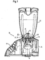
- FIG. 1 shows a kitchen appliance 10 in a schematic sectional view.
- the kitchen appliance 10 is a so-called. Mischzerklein ceremoniessvoriques, which is also referred to below with the reference numeral 10.
- the mixing crushing device 10 has a rotating tool shaft 12 and comprises a housing 14 with a drive device, preferably an electric drive motor 16, and an operating element 18 for operating the functions of the kitchen appliance 10.
- the tool shaft 12 with knives 20 arranged thereon has a vertical axis of rotation and projects into a cup 22 which is placed and locked in a receptacle 15 on an upper side of the housing 14 and can be removed if necessary.
- the cup 22 has an open bottom portion 24 with an annular collar 26 which has a cylindrical outer surface with an external thread or a bayonet fitting or the like thereon. This corresponds to a corresponding internal thread or a counter-fit of a bayonet lock a cup carrier 28.
- the cup carrier 28 can be removed together with the cup 22 from the housing 14 and seals in this case, the open bottom portion 24 of the cup 22 from.
- the cup 22 is against the cup carrier 28 by means of an annular Seal 58 sealed (see Figure 2).
- annular Seal 58 sealed (see Figure 2).
- the cup carrier 28 can preferably be locked in the receptacle 15 by means of a bayonet closure 29.
- FIG. 2 and 5 illustrate the structure and the interaction of the essential elements of a start-up protection of the kitchen appliance 10 in a detail section.
- the tool shaft 12 is free with the knives 20 anchored thereto (see FIG.
- the drive motor 16 is decoupled from the tool shaft 12.
- a coupling 32 is provided between an output shaft 34 of the drive motor and the tool shaft 12, which interrupts the adhesion at an axial displacement of the tool shaft 12 upwards.
- a concentrically arranged around the clutch 32 spring 36 is supported on the one hand on a housing shoulder 38 and on the other hand on an axially movable cover 40, which is connected via a sleeve 42 with the bearing plate 30 in connection.
- the spring 36 presses the cover 40 up to an upper stop 44 which is part of a bell housing 45 of the housing 14. Seated on the cover 40 sleeve 42 pushes the bearing plate 30 so far up that the clutch 32 is separated and the tool shaft 12 is brought out of engagement with the output shaft 34 of the drive motor 16.
- a between the bell housing 45 in the receptacle 15 and the cover 40 remaining space serves as a closable opening 43, which is closed with removed cup carrier 28 and with the cup 22 removed.
- the opening 43 serves to ventilate the drive motor 16, which would be subject to excessive heating in a closed housing 14 and prolonged operation.
- the heat loss can be dissipated by a ventilation device, which ensures an air supply through the opening 43 and a downward discharge of the air (see Figure 4).
- the circular bearing plate 30 has a roof-shaped contour with an inner, tubular portion 46, in the partially cylindrical inner lateral surface of an elongated sliding bearing is used as a shaft bearing 50, which forms an axial and radial bearing for the tool shaft 12.
- the bearing plate 30 has an adjoining bowl-shaped central portion 48, on the underside of the sleeve 42 abuts.
- a subsequent annular outer portion 52 of the bearing plate 30 is stepped, so that a transition of the bowl-shaped central portion 48 is formed into a short hollow cylindrical portion 54.
- At its upper edge sets with a small radius of the outer edge of the central portion 48 at.
- a disc-shaped ring 56 is attached, which forms a support for the seal 58.
- the cup 22 of the bearing plate 30 When placing the cup 22 of the bearing plate 30 is centered in the cup carrier 28 at the same time. This is preferably done by a fit of the inner circumferential surface of the hollow cylindrical portion 54 on a centering collar 64 which projects upwardly at the inner radius of the annular groove 62 and ensures a proper fit of the bearing plate 30. However, the centering can also take place between the outer circumference of the ring 56 and the internal thread 60 of the cup carrier 28. At the same time, the annular groove 62 forms a stop in the axial direction.
- FIG. 3 shows a detailed view of the open receptacle 15 for insertion of the receptacle 15 Cup carrier 28, in which for better clarity, the cover 40 is located at its lower stop. This makes it clear that 40 parts of a cylindrical outer circumferential surface of the output clutch 35 would be freely accessible without the upwardly pressing cover.
- the arranged thereon engagement elements which can be brought into engagement with a drive coupling 37 of the tool shaft 12 in the axial direction, are exposed and may result in a rotation of the output shaft 34 may cause injury.
- the engagement elements arranged on the cylindrical outer circumference of the output coupling 35 can in particular consist of rounded webs which can engage in grooves mating therewith in the inner lateral surface of the drive coupling 37.
- the webs or grooves are preferably located exclusively on the lateral surface of the respective couplings, so that in particular the front side of the output coupling 35 has no paragraphs or projections o. The like., Which can lead to injury in case of accidental contact.
- the inventive arrangement is characterized by a compact design, since the concentrically arranged around the output shaft 34 spring 36 and the enclosing bell housing 45 need no additional space. The few moving parts ensure reliable and largely trouble-free operation.
- Figure 7 illustrates the relatively smooth-surfaced and visually appealing design of the receptacle 15 with removed cup carrier 28th
- FIG. 4 illustrates a cooling air flow 80 through the kitchen appliance 10, which first passes through the shaft bearing 50 of the tool shaft 12, the coupling 32 and then the drive motor 16 before it exits downwards through an air outlet or an additional opening 72.
- the cooling air flow 80 is effected by a fan 66 which is arranged on a lower stub shaft 78 of the motor shaft.
- the fan 66 causes a deflection of an axial into a radial flow by sucking the air from the motor 16 axially and leak in the radial direction.
- a gap 70 is provided as an air inlet, through which the air is sucked.
- the air flows under the bearing plate 30 which carries the shaft bearing 50 for the tool shaft 12 and ensures sufficient heat dissipation from this sliding bearing.
- an annular opening 43 is arranged, which forms a cooling air passage to the drive motor 16. Through this opening 43, the cooling air flow enters and cools while passing the clutch 32, which makes a flexing work due to their elasticity and is heated. The still relatively cool air then flows through the drive motor 16, wherein the cooling air flow 80, if necessary, divides between existing gaps, for example.
- the air-sucking fan 66 which presses the air in the radial direction to the outside and through an additional opening 72.
- the additional opening 72 is designed as a bottom opening in the housing bottom 68. Possibly.
- the additional opening 72 can be provided with a sieve or grid (not shown), so that no foreign bodies can penetrate into the lower housing area and collide with the fan 66.
- a partition wall 74 seals off the lower housing area from the uppermost area and prevents a flow of cooling air past the drive motor 16, since otherwise parts of the air flowing through the opening 43 could be sucked directly by the fan 66, without the gaps between the rotor 17 and Stator 19 to pass.
- the opening 43 in the area around the coupling 32 can be closed.
- Figures 5 and 6 illustrate the closeability of the opening 43 with removed cup carrier 28.
- the opening 43 With the voltage applied to the upper stop 44 cover 40, the opening 43 is closed, so that the inside of the housing is reliably protected against the ingress of dirt and / or moisture.
- an annular gap 41 is formed between the housing 14 and the output coupling 35.
- the cover 40 is annular and is linearly reciprocally movable in the annular gap 41 coaxial with the output coupling 35 from the closed position to the open position.
- the mixer comminution device 10 is also suitable for continuous operation and heavy duty due to the effective cooling of all parts which are heated during operation.
- Both the shaft bearing 50 of the tool shaft 12 and the typically made of elastic plastic coupling 32 is subject to heavy operating conditions and thus a significant heating depending on the operating conditions. This heat development can be removed from the housing 14 by means of the cooling air flow 80 running in accordance with FIG.
Landscapes
- Engineering & Computer Science (AREA)
- Mechanical Engineering (AREA)
- Food Science & Technology (AREA)
- Food-Manufacturing Devices (AREA)
- Closures For Containers (AREA)
- Table Devices Or Equipment (AREA)
- Cookers (AREA)
- Motor Or Generator Frames (AREA)
Abstract
Description
Die Erfindung betrifft ein Küchengerät mit den im Oberbegriff des Patentanspruchs 1 genannten Merkmalen.The invention relates to a kitchen appliance with the features mentioned in the preamble of patent claim 1.
Küchengeräte benötigen oftmals eine Kühleinrichtung. Für kleinere Geräte kommt vorwiegend eine Luftkühlung mittels einer Kühlluftströmung in Frage, die auf einfache Weise durch einen vom Antriebsmotor betriebenen Ventilator erzeugt werden kann. Für eine effektive Kühlluftführung ist ein Lufteinlass und ein Luftauslass notwendig, die typischerweise jeweils an gegenüber liegenden Seiten eines Gehäuses angeordnet sind. Ein Beispiel für ein derartiges motorbetriebenes Küchengerät ist eine Mischzerkleinerungsvorrichtung für den Haushalt. Diese weist typischerweise ein Motorgehäuse mit einem elektrischen Antriebsmotor und einen auf eine Oberseite des Gehäuses aufsetzbaren Becher auf, in dessen unterem Bereich eine Werkzeugwelle um eine vertikale Achse rotieren kann. Der unten offene Becher kann normalerweise mitsamt einem Becherträger vom Gehäuse abgenommen werden, um den darin zuvor zerkleinerten und/oder fein durchmischten Inhalt in ein Gefäß entleeren zu können.Kitchen appliances often require a cooling device. For smaller devices is mainly an air cooling means of a cooling air flow in question, which can be generated in a simple manner by a fan operated by the drive motor. Effective cooling air routing requires an air inlet and outlet that are typically located on opposite sides of a housing. An example of such a powered kitchen appliance is a household mixing mixer. This typically has a motor housing with an electric drive motor and a cup which can be placed on an upper side of the housing, in the lower region of which a tool shaft can rotate about a vertical axis. The cup, which is open at the bottom, can normally be removed from the casing together with a cup carrier, in order to be able to empty the previously comminuted and / or finely mixed contents into a container.
Es sind Kühleinrichtungen bekannt, um die im Antriebsmotor einer Mischzerkleinerungsvorrichtung bei länger andauerndem Betrieb entstehende Verlustwärme abzuführen. So zeigt die DE 17 78 820 C3 eine gattungsgemäße Misch- und Zerkleinerungsvorrichtung für den Haushalt, die ein Gehäuse mit einem darin angeordneten Antriebsmotor und einer von diesem betriebenen, vertikal innerhalb eines Behälters rotierenden Messerwelle aufweist. Ein unterer Wellenstumpf des Motors ist mit einem Lüfterflügel versehen, der die im Gehäuse entstehende Verlustwärme durch Öffnungen im Gehäuseboden nach außen führt.Cooling devices are known in order to dissipate the heat loss arising in the drive motor of a mixing crushing device during prolonged operation. Thus,
Eine Aufgabe der vorliegenden Erfindung besteht darin, bei einem motorbetriebenem elektrischen Gerät, insbesondere bei einer gattungsgemäßen Mischzerkleinerungsvorrichtung die Kühlung von sich im Betrieb erwärmenden Geräteteilen zu verbessern.It is an object of the present invention to improve the cooling of device parts which heat up during operation in a motor-driven electrical device, in particular in a generic mixing / crushing device.
Diese Aufgabe wird bei einem elektrischen Gerät mit den im Patentanspruch 1 genannten Merkmalen dadurch gelöst, dass eine Abdeckung vorgesehen ist, die eine offene Stellung einnehmen kann, in der die Öffnung offen ist, und die eine geschlossene Stellung einnehmen kann, in der die Öffnung geschlossen ist, und dass die Abdeckung durch das in Einkuppeln der Antriebskupplung mit der Abtriebskupplung in die offene Stellung bringbar ist. Gegenüber herkömmlichen luftgekühlten elektrischen Geräten mit reiner Motorkühlung wird bei dem erfindungsgemäßen Gerät zusätzlich eine Wellenlagerung und/oder eine zwischen Werkzeugwelle und Abtriebswelle des Antriebsmotors angeordnete Kupplung gekühlt. Da eine solche axial trennbare Kupplung normalerweise eine gewisse materialbedingte Elastizität aufweist, entsteht durch Walkarbeit Wärme, welche die Lebensdauer beeinträchtigen und die durch eine gezielte Luftführung effektiv abgeführt werden kann. Ebenso kann sich bei einer gleitgelagerten Werkzeugwelle bei länger dauerndem Betrieb Wärme entwickeln, die durch die einseitige Kapselung der Lagerung relativ schlecht abgeführt werden kann. Durch die erfindungsgemäße gezielte Luftkühlung auch dieser Lagerung kann deren Lebensdauer erhöht werden. Die Erfindung sieht vor, dass der Lufteinlass an der Gehäuseoberseite verschließbar ist. Dies kann insbesondere durch einen Mechanismus erfolgen, der bei abgenommener Werkzeugwelle eine obere Gehäuseöffnung zwischen Lagerung der Werkzeugwelle und Antriebsmotor verschließt. Hierdurch wird bei abgenommenem Becher das Eindringen von Schmutz und/oder Feuchtigkeit durch den oberen Lufteinlass verhindert.This object is achieved in an electrical device with the features mentioned in claim 1 in that a cover is provided which can take an open position in which the opening is open, and which can assume a closed position in which the opening is closed is, and that the cover can be brought by the engagement of the drive clutch with the output clutch in the open position. Compared to conventional air-cooled electrical devices with pure engine cooling, a shaft bearing and / or a coupling arranged between the tool shaft and the output shaft of the drive motor is additionally cooled in the device according to the invention. Since such axially separable coupling normally has a certain material-related elasticity, created by flexing heat, which affect the life and can be effectively dissipated by a targeted air flow. Likewise, heat can develop in a slide-mounted tool shaft during prolonged operation, which can be dissipated by the one-sided encapsulation of storage relatively poor. The inventive targeted air cooling and this storage their life can be increased. The invention provides that the air inlet is closable on the upper side of the housing. This can be done, in particular, by a mechanism which, with the tool shaft removed, closes an upper housing opening between the bearing of the tool shaft and the drive motor. As a result, the penetration of dirt and / or moisture is prevented by the upper air inlet with the cup removed.
Eine Ausführungsform der Erfindung sieht vor, dass die Abdeckung durch eine Feder in der geschlossenen Stellung vorgespannt gehalten wird. Hierdurch kann sichergestellt werden, dass die Abdeckung durch die Federkraft geschlossen gehalten wird, sobald die Werkzeugwelle vom Gehäuse abgenommen ist.An embodiment of the invention provides that the cover is held biased by a spring in the closed position. This can ensure that the cover is kept closed by the spring force as soon as the tool shaft is removed from the housing.
Vorzugsweise ist durch die Kraft der Feder die Antriebskupplung in eine gegenüber der Abtriebskupplung ausgekuppelte Stellung bringbar. Dadurch kann sichergestellt werden, dass die Werkzeugwelle sich nicht mehr drehen kann, sobald sie vom Gehäuse abgenommen ist.Preferably, the drive coupling can be brought into a disengaged from the output coupling position by the force of the spring. This can ensure that the tool shaft can not rotate as soon as it is removed from the housing.
Die Abdeckung sorgt in der geschlossenen Stellung für eine Abdeckung der Abtriebskupplung, so dass keine Fremdkörper, Schmutz oder Feuchtigkeit in das Gehäuse eindringen können.In the closed position, the cover provides a cover for the output coupling, so that no foreign bodies, dirt or moisture can penetrate into the housing.
Weiterhin kann vorgesehen sein, dass in geöffneter Stellung der Abdeckung der Kühlluftkanal zum Leiten von Kühlluft für den Antriebsmotor und/oder die Kupplung und /oder die Wellenlagerung freigegeben wird, so dass die genannten Teile während des Betriebs optimal gekühlt werden können.Furthermore, it can be provided that in the open position of the cover of the cooling air passage for guiding cooling air for the drive motor and / or the clutch and / or the shaft bearing is released, so that said parts can be optimally cooled during operation.
Eine Ausgestaltung der Erfindung sieht vor, dass die Öffnung benachbart zur Abtriebskupplung angeordnet ist. Damit kann erreicht werden, dass die Kupplung unmittelbar dem Kühlluftstrom ausgesetzt ist, sobald sich die Werkzeugwelle dreht.An embodiment of the invention provides that the opening is arranged adjacent to the output coupling. This can be achieved that the coupling is exposed directly to the cooling air flow as soon as the tool shaft rotates.
Eine weitere Ausführungsform der Erfindung sieht vor, dass am Antriebsmotor ein Ventilator angeordnet ist, der einen Kühlluftstrom durch den Kühlluftkanal erzeugt. Hierzu kann der Ventilator in vorteilhafter Weise direkt mit der Motorwelle gekoppelt sein. Insbesondere kann er auf einen Wellenstumpf der Abtriebswelle aufgesetzt sein, so dass der Lüfterflügel mit der Motordrehzahl rotiert und für eine effektive Kühlung sorgen kann. Die Ausgestaltung der Flügel sowie deren Anzahl und Größe kann den Luftdurchsatz bei bekannter Motordrehzahl definieren. Eine bevorzugte Position des Lüfterflügels kann auf einer der Messerwelle gegenüber liegenden unteren Seite des Antriebsmotors sein, wo er in Platz sparender Weise untergebracht werden kann. Typischerweise ist der untere Wellenstumpf ohnehin aus dem Motor herausgeführt und mit einem Lager versehen, so dass der Lüfterflügel problemlos zwischen Motor und Gehäuselagerung untergebracht werden kann.A further embodiment of the invention provides that a fan is arranged on the drive motor, which generates a cooling air flow through the cooling air duct. For this purpose, the fan may advantageously be coupled directly to the motor shaft. In particular, it can be placed on a stub shaft of the output shaft, so that the fan blade rotates at the engine speed and can provide effective cooling. The design of the wings and their number and size can define the air flow at a known engine speed. A preferred position of the fan blade may be on a blade shaft opposite the lower side of the drive motor, where it can be accommodated in a space-saving manner. Typically, the lower stub shaft is led out of the engine anyway and provided with a bearing, so that the fan blades can be easily accommodated between the engine and housing mounting.
Vorzugsweise hat der Kühlluftkanal einen Spalt zwischen einem Bodenabschnitt des Bechers und Gehäuse, und eine zur Öffnung entfernte zusätzliche Öffnung im Gehäuse. Die Kühlluft tritt vorzugsweise am Spalt ein, wird am Wellenlager und an der Kupplung vorbeigeführt, tritt über die Öffnung ins Innere des Gehäuses ein, strömt durch den Antriebsmotor und tritt über die zusätzliche Öffnung wieder aus dem Gehäuse aus. Damit wird eine effektive Kühlung aller sich im Betrieb erwärmenden Teile des Küchengeräts sichergestellt.Preferably, the cooling air passage has a gap between a bottom portion of the cup and the casing, and an additional opening in the casing remote from the opening. The cooling air preferably enters the gap, is guided past the shaft bearing and on the coupling, enters the interior of the housing via the opening, flows through the drive motor and exits the housing via the additional opening. This ensures effective cooling of all parts of the kitchen appliance that are warming during operation.
Vorzugsweise hat der Becher einen Becherträger und einen das Wellenlager tragenden Lagerschild, wobei der Becherträger über eine Verschlusseinrichtung, bevorzugt einen Bajonettverschluss am Gehäuse montierbar ist. Der Lagerschild kann somit einfach fixiert werden, so dass die darin gelagerte Werkzeugwelle stabil im Gehäuse gelagert ist.Preferably, the cup has a cup carrier and a shaft bearing bearing bearing plate, wherein the cup carrier via a closure device, preferably a Bayonet lock can be mounted on the housing. The bearing plate can thus be easily fixed, so that the tool shaft mounted therein is stably supported in the housing.
Weiterhin kann vorgesehen sein, dass der Becher am Becherträger über eine Verbindungseinrichtung, bevorzugt ein Gewinde, montierbar ist und bei auf dem Becherträger montiertem Becher zwischen dem Becher und dem Becherträger der Lagerschild angeordnet ist. Der Lagerschild und damit die Werkzeugwelle sind somit stabil gelagert.Furthermore, it can be provided that the cup on the cup carrier via a connecting device, preferably a thread, can be mounted and is arranged in mounted on the cup carrier cup between the cup and the cup carrier of the bearing plate. The bearing plate and thus the tool shaft are thus stably supported.
Eine Ausgestaltung der Erfindung sieht vor, dass bei am Gehäuse montiertem Becherträger und nicht am Becherträger montiertem Becher der Lagerschild mit Lagerwelle und der Antriebskupplung mittels der vorgespannten Abdeckung derart bewegt wird, dass die Antriebskupplung von der Abtriebskupplung entkuppelt wird. Somit sorgt das Abnehmen des Bechers vom Becherträger für ein Öffnen der Kupplung und dafür, dass sich die frei liegende Werkzeugwelle nicht drehen kann.An embodiment of the invention provides that when mounted on the housing cup carrier and not mounted on the cup carrier mug the bearing plate with bearing shaft and the drive coupling is moved by means of biased cover such that the drive coupling is decoupled from the output coupling. Thus, removing the cup from the cup carrier will open the coupling and prevent the exposed tool shaft from rotating.
Vorzugsweise ist zwischen dem Gehäuse und der Abtriebskupplung ein ringförmiger Spalt ausgebildet. Vorzugsweise ist die Abdeckung ringförmig ausgebildet und in dem ringförmigen Spalt koaxial zur Abtriebskupplung von der geschlossenen Stellung in die geöffnete Stellung linear hin und her beweglich. Vorzugsweise ist weiterhin vorgesehen, dass die Abdeckung in der geschlossenen Stellung einen Anschlag hat und bündig zum benachbarten Gehäuseabschnitt und/oder zum stimseitigen Ende der Abtriebskupplung positioniert ist. Die Abdeckung sorgt somit bei abgenommenem Becher und/oder Becherträger für ein Verschließen des Spalts und dafür, dass kein Schmutz oder Feuchtigkeit eindringen können.Preferably, an annular gap is formed between the housing and the output coupling. Preferably, the cover is annular and is linearly reciprocable in the annular gap coaxial with the output coupling from the closed position to the open position. Preferably, it is further provided that the cover has a stop in the closed position and is positioned flush with the adjacent housing portion and / or the end of the driven output coupling. The cover thus ensures with the removed cup and / or cup carrier for closing the gap and that no dirt or moisture can penetrate.
Weitere Aspekte und vorteilhafte Weiterbildungen der Erfindung ergeben sich aus den abhängigen Ansprüchen sowie aus der nachfolgenden Figurenbeschreibung.Further aspects and advantageous developments of the invention will become apparent from the dependent claims and from the following description of the figures.
Nachstehend wird die Erfindung anhand eines Ausführungsbeispiel unter Bezugnahme auf die beiliegenden Zeichnungen näher erläutert. Dabei zeigt:
- Figur 1
- eine schematische Schnittdarstellung eines beispielhaften Küchengeräts,
- Figur 2
- einen Detailschnitt des Küchengeräts entsprechend Figur 1 mit aufgesetztem Becher,
- Figur 3
- eine Detailansicht einer Aufnahme für einen Becherträger des Bechers mit freiliegender Abtriebswelle,
- Figur 4
- einen Detailschnitt eines Gehäuses des Geräts mit darin verlaufender Kühlluftströmung,
- Figur 5
- einen Detailschnitt entsprechend Figur 2 mit abgenommenem Becher,
- Figur 6
- einen weiteren Detailschnitt eines oberen Bereichs des Küchengeräts mit verschlossenen oberen Lufteinlässen und
- Figur 7
- eine weitere Detailansicht der Aufnahme für den Becherträger mit weitgehend bündig abgeschirmter Abtriebswelle.
- FIG. 1
- a schematic sectional view of an exemplary kitchen appliance,
- FIG. 2
- a detail section of the kitchen appliance according to Figure 1 with attached cup,
- FIG. 3
- a detailed view of a receptacle for a cup carrier of the cup with exposed output shaft,
- FIG. 4
- a detail section of a housing of the device with cooling air flow extending therein,
- FIG. 5
- a detail section corresponding to Figure 2 with removed cup,
- FIG. 6
- a further detail section of an upper portion of the kitchen appliance with sealed upper air inlets and
- FIG. 7
- another detail view of the receptacle for the cup carrier with a largely flush shielded output shaft.
Figur 1 zeigt ein Küchengerät 10 in einer schematischen Schnittdarstellung. Im gezeigten Ausführungsbeispiel ist das Küchengerät 10 eine sog. Mischzerkleinerungsvorrichtung, die im Folgenden ebenfalls mit der Bezugsziffer 10 bezeichnet wird. Die Mischzerkleinerungsvorrichtung 10 weist eine rotierende Werkzeugwelle 12 auf und umfasst ein Gehäuse 14 mit einer darin angeordneten Antriebsvorrichtung, vorzugsweise einem elektrischen Antriebsmotor 16, sowie einem Bedienelement 18 zur Bedienung der Funktionen des Küchengeräts 10. Die Werkzeugwelle 12 mit daran angeordneten Messern 20 weist eine vertikale Drehachse auf und ragt in einen Becher 22, der in eine Aufnahme 15 auf einer Oberseite des Gehäuses 14 aufgesetzt und verriegelt ist und bei Bedarf hiervon abgenommen werden kann. Der Becher 22 weist einen offenen Bodenabschnitt 24 mit einem ringförmigen Bund 26 auf, der eine zylindrische Außenmantelfläche mit einem darauf befindlichen Außengewinde oder einer Bajonettpassung o. dgl. aufweist. Diese korrespondiert mit einem entsprechenden Innengewinde bzw. einer Gegenpassung einer Bajonettverriegelung eines Becherträgers 28. Der Becherträger 28 kann gemeinsam mit dem Becher 22 vom Gehäuse 14 abgenommen werden und dichtet in diesem Fall den offenen Bodenabschnitt 24 des Bechers 22 ab. Der Becher 22 ist gegen den Becherträger 28 mittels einer ringförmigen Dichtung 58 abgedichtet (vgl. Figur 2). Bei fest mit dem Becherträger 28 verbundenem Becher 22 bleibt die Werkzeugwelle 12 auch bei abgenommenem Becher 22 mit diesem verbunden, da die Werkzeugwelle 12 in einem Lagerschild 30 gelagert ist, der zwischen Becher 22 und Becherträger 28 fixiert ist. Der Becherträger 28 kann vorzugsweise mittels eines Bajonettverschlusses 29 in der Aufnahme 15 verriegelt werden.Figure 1 shows a
Die Figuren 2 und 5 verdeutlichen den Aufbau und das Zusammenwirken der wesentlichen Elemente einer Anlaufsicherung des Küchengeräts 10 in einem Detailschnitt. Sobald der Becher 22 vom Becherträger 28 abgenommen ist, liegt die Werkzeugwelle 12 mit den daran verankerten Messern 20 frei (vgl. Figur 5). Um zu verhindern, dass die rotierenden Messer 20 bei einer Berührung zu Verletzungen führen können, ist in diesem Fall der Antriebsmotor 16 von der Werkzeugwelle 12 entkoppelt. Zu diesem Zweck ist eine Kupplung 32 zwischen einer Abtriebswelle 34 des Antriebsmotors und der Werkzeugwelle 12 vorgesehen, die bei einer axialen Verschiebung der Werkzeugwelle 12 nach oben den Kraftschluss unterbricht. Eine konzentrisch um die Kupplung 32 angeordnete Feder 36 stützt sich einerseits an einem Gehäuseabsatz 38 und andererseits an einer axial beweglichen Abdeckung 40 ab, die über eine Hülse 42 mit dem Lagerschild 30 in Verbindung steht. Bei abgenommenem Becher 22 drückt die Feder 36 die Abdeckung 40 bis zu einem oberen Anschlag 44 nach oben, der Teil einer Gehäuseglocke 45 des Gehäuses 14 ist. Die auf der Abdeckung 40 aufsitzende Hülse 42 drückt den Lagerschild 30 so weit nach oben, dass die Kupplung 32 getrennt und die Werkzeugwelle 12 aus ihrem Eingriff mit der Abtriebswelle 34 des Antriebsmotors 16 gebracht ist.Figures 2 and 5 illustrate the structure and the interaction of the essential elements of a start-up protection of the
Ein zwischen der Gehäuseglocke 45 in der Aufnahme 15 und der Abdeckung 40 verbleibender Zwischenraum dient als verschließbare Öffnung 43, die bei abgenommenem Becherträger 28 bzw. bei abgenommenem Becher 22 verschlossen wird. Die Öffnung 43 dient zur Belüftung des Antriebsmotors 16, der bei einem geschlossenen Gehäuse 14 und länger andauerndem Betrieb einer zu starken Erwärmung unterliegen würde. Die Verlustwärme kann durch eine Ventilationseinrichtung abgeführt werden, die für eine Luftzufuhr durch die Öffnung 43 und eine Abfuhr der Luft nach unten (vgl. Figur 4) sorgt.A between the
Der kreisrunde Lagerschild 30 weist eine dachförmige Kontur mit einem inneren, rohrförmigen Abschnitt 46 auf, in dessen abschnittsweise zylindrische Innenmantelfläche ein längliches Gleitlager als Wellenlager 50 eingesetzt ist, das eine axiale und radiale Lagerung für die Werkzeugwelle 12 bildet. Der Lagerschild 30 weist einen daran anschließenden schüsselförmigen mittleren Abschnitt 48 auf, an dessen Unterseite die Hülse 42 anliegt. Ein hieran anschließender ringförmiger äußerer Abschnitt 52 des Lagerschilds 30 ist gestuft ausgebildet, so dass ein Übergang des schüsselförmigen mittleren Abschnitts 48 zu einem kurzen hohlzylindrischen Abschnitt 54 gebildet ist. An dessen oberem Rand setzt mit kleinem Radius der äußere Rand des mittleren Abschnitts 48 an. Am unteren Rand des hohlzylindrischen Abschnitts 54 ist ein scheibenförmiger Ring 56 angesetzt, der eine Auflage für die Dichtung 58 bildet.The
Bei auf den Becherträger 28 aufgesetztem Becher 22 ist dessen, mit einem Außengewinde versehener Bund 26 mit dem Innengewinde 60 des Becherträgers 28 verschraubt (Figur 2). Hierbei drückt die untere ringförmige Kante am Bund 26 des Bechers 22 den Ring 56 des Lagerschilds 30 gegen die Rückstellkraft der Feder 36 nach unten, bis der Ring 56 auf einem Grund einer Ringnut 62 des Schüsselträgers 28 aufliegt. Die ringförmige Dichtung 58 sorgt hierbei für die Abdichtung des Bechers 22 gegen den nach unten geschlossenen Becherträger 28.When mounted on the
Beim Aufsetzen des Bechers 22 wird gleichzeitig der Lagerschild 30 im Becherträger 28 zentriert. Dies erfolgt vorzugsweise durch eine Passung der Innenmantelfläche des hohlzylindrischen Abschnitts 54 auf einem Zentrierbund 64, der am inneren Radius der Ringnut 62 nach oben ragt und für einen passenden Sitz des Lagerschilds 30 sorgt. Die Zentrierung kann jedoch auch zwischen dem äußeren Umfang des Rings 56 und dem Innengewinde 60 des Becherträgers 28 erfolgen. Gleichzeitig bildet die Ringnut 62 einen Anschlag in axialer Richtung.When placing the
Um zu verhindern, dass bei abgenommenem Becher 22 Teile der Abtriebswelle 34 frei liegen und berührt werden können, drückt die Feder 36 die Abdeckung 40 zumindest so weit nach oben gegen den Anschlag 44 der Gehäuseglocke 45, dass eine mit der Abtriebswelle 34 des Antriebsmotors 16 verbundene Abtriebskupplung 35 nur noch stirnseitig frei liegt. Dieser Zustand ist anhand der Figuren 6 und 7 verdeutlicht. Figur 3 zeigt eine Detailansicht der offen liegenden Aufnahme 15 zum Einsetzen des Becherträger 28, bei der zur besseren Verdeutlichung die Abdeckung 40 an ihrem unteren Anschlag liegt. Hierdurch wird deutlich, dass ohne die nach oben drückende Abdeckung 40 Teile einer zylindrischen Außenmantelfläche der Abtriebskupplung 35 frei zugänglich wären. Die daran angeordneten Eingriffselemente, die mit einer Antriebskupplung 37 der Werkzeugwelle 12 in axialer Richtung in Eingriff gebracht werden können, liegen frei und können bei einer Rotation der Abtriebswelle 34 unter Umständen zu Verletzungen führen.In order to prevent 22 parts of the
Wie anhand der Figur 3 deutlich gemacht wird, können die am zylindrischen Außenumfang der Abtriebskupplung 35 angeordneten Eingriffselemente insbesondere aus abgerundeten Stegen bestehen, die in hierzu passende Nuten in der Innenmantelfläche der Antriebskupplung 37 eingreifen können. Die Stege bzw. Nuten befinden sich vorzugsweise ausschließlich an den Mantelfläche der jeweiligen Kupplungen, so dass insbesondere die Stirnseite der Abtriebskupplung 35 keine Absätze oder Vorsprünge o. dgl. aufweist, die bei einer versehentlichen Berührung zu Verletzungen führen können.As is made clear with reference to FIG. 3, the engagement elements arranged on the cylindrical outer circumference of the
Die erfindungsgemäße Anordnung zeichnet sich durch eine kompakte Bauweise aus, da die konzentrisch um die Abtriebswelle 34 angeordnete Feder 36 und die umhüllende Gehäuseglocke 45 keinen zusätzlichen Bauraum benötigen. Die wenigen bewegten Teile stellen eine zuverlässige und weitgehend störungsfreie Funktion sicher.The inventive arrangement is characterized by a compact design, since the concentrically arranged around the
Durch die geschlossene Öffnung 43 kann keine Feuchtigkeit oder Schmutz in das Geräteinnere dringen. Zudem verdeutlicht die Figur 7 die relativ glattflächige und optisch ansprechende Gestaltung der Aufnahme 15 bei abgenommenem Becherträger 28.Through the
Figur 4 verdeutlicht einen Kühlluftstrom 80 durch das Küchengerät 10, der zunächst das Wellenlager 50 der Werkzeugwelle 12, die Kupplung 32 und anschließend den Antriebsmotor 16 durchstreicht, bevor sie nach unten durch einen Luftauslass bzw. eine zusätzliche Öffnung 72 austritt. Der Kühlluftstrom 80 wird durch einen Ventilator 66 bewirkt, der auf einem unteren Wellenstumpf 78 der Motorwelle angeordnet ist. Der Ventilator 66 bewirkt eine Umlenkung einer axialen in eine radiale Strömung, indem er die Luft aus dem Motor 16 axial ansaugt und in radialer Richtung austreten lässt.FIG. 4 illustrates a cooling
Zwischen Gehäusedeckel 76 und Schüsselträger 28 ist ein Spalt 70 als Lufteinlass vorgesehen, durch den die Luft angesaugt wird. Die Luft strömt unter den Lagerschild 30, der das Wellenlager 50 für die Werkzeugwelle 12 trägt und sorgt für eine ausreichende Wärmeabfuhr von diesem Gleitlager. Konzentrisch um die Kupplung 32 ist eine ringförmige Öffnung 43 angeordnet, die einen Kühlluftkanal zum Antriebsmotor 16 bildet. Durch diese Öffnung 43 tritt der Kühlluftstrom ein und kühlt dabei beim Vorbeistreichen die Kupplung 32, die aufgrund ihrer Elastizität eine Walkarbeit leistet und dabei erwärmt wird. Die immer noch relativ kühle Luft durchströmt anschließend den Antriebsmotor 16, wobei sich der Kühlluftstrom 80 ggf. zwischen vorhandenen Spalten, bspw. zwischen Stator 19 und Rotor 17 aufteilt, wie dies in Figur 4 angedeutet ist.Between
Unmittelbar unterhalb des Motors 16 sitzt der die Luft ansaugende Ventilator 66, der die Luft in radialer Richtung nach außen und durch eine zusätzliche Öffnung 72 drückt. Im gezeigten Ausführungsbeispiel ist die zusätzliche Öffnung 72 als Bodenöffnung im Gehäuseboden 68 ausgestaltet. Ggf. kann die zusätzliche Öffnung 72 mit einem Sieb oder Gitter (nicht dargestellt) versehen sein, damit keine Fremdkörper in den unteren Gehäusebereich eindringen und mit dem Ventilator 66 kollidieren können. Eine Trennwand 74 schottet den unteren Gehäusebereich gegen den weiter oben liegenden Bereich ab und verhindert eine Strömung der Kühlluft am Antriebsmotor 16 vorbei, da ansonsten Teile der durch die Öffnung 43 strömenden Luft unmittelbar vom Ventilator 66 angesaugt werden könnten, ohne die Spalten zwischen Rotor 17 und Stator 19 zu passieren.Immediately below the
Um zu verhindern, dass bei abgenommenem Becher 22 bzw. bei aus der Aufnahme 15 abgenommenem Becherträger 28 Fremdkörper in das Motorinnere gelangen können, ist die Öffnung 43 im Bereich um die Kupplung 32 verschließbar ausgestaltet. Die Figuren 5 und 6 verdeutlichen die Verschließbarkeit der Öffnung 43 bei abgenommenem Becherträger 28. Mit der am oberen Anschlag 44 anliegenden Abdeckung 40 wird die Öffnung 43 verschlossen, so dass das Gehäuseinnere zuverlässig gegen das Eindringen von Schmutz und/oder Feuchtigkeit geschützt ist. Zwischen dem Gehäuse 14 und der Abtriebskupplung 35 ist ein ringförmiger Spalt 41 ausgebildet. Auch die Abdeckung 40 ist ringförmig ausgebildet und in dem ringförmigen Spalt 41 koaxial zur Abtriebskupplung 35 von der geschlossenen Stellung in die geöffnete Stellung linear hin und her beweglich ist.In order to prevent foreign matter from entering the interior of the engine when the
Die erfindungsgemäße Mischerzerkleinerungsvorrichtung 10 ist aufgrund der effektiven Kühlung aller sich im Betrieb erwärmenden Teile auch für einen Dauerbetrieb und eine harte Beanspruchung geeignet. Sowohl das Wellenlager 50 der Werkzeugwelle 12 als auch die typischerweise aus elastischem Kunststoff bestehende Kupplung 32 unterliegt je nach Betriebsbedingungen einer starken Beanspruchung und damit einer deutlichen Erwärmung. Diese Wärmeentwicklung kann mittels des entsprechend Figur 4 verlaufenden Kühlluftstroms 80 aus dem Gehäuse 14 abgeführt werden.The
Claims (14)
- Kitchen appliance with a housing (14) and a beaker (22) removable from the housing (14), a drive motor (16) disposed in the housing (14), a tool shaft (12), which is arranged in the beaker (22) and mounted by way of a shaft bearing (50), of a coupling (32), which has a driven coupling (35) arranged at the drive motor (16) and a drive coupling (37) arranged at the tool shaft (12) and adapted to the driven coupling (35), and a cooling air channel with an opening (43) provided at the housing (14), characterised in that a cover (40) is provided, which can adopt an open setting in which the opening (43) is open and can adopt a closed setting in which the opening (43) is closed, and that the cover (40) can be brought into the open setting by coupling the drive coupling (37) with the driven coupling (35).
- Kitchen appliance according to claim 1, characterised in that the cover (40) is held by a spring (36) to be biased into the closed setting.
- Kitchen appliance according to claim 1 or 2, characterised in that the drive coupling (27) can be brought by the force of the spring (26) into the setting uncoupled relative to the driven coupling (35).
- Kitchen appliance according to one of claims 1 to 3, characterised in that the cover (40) in the closed setting covers the driven coupling (25).
- Kitchen appliance according to one of the preceding claims, characterised in that in the opened setting of the cover (40) the cooling air channel is freed for guidance of cooling air for the drive motor (16) and/or the coupling (32) and/or the shaft bearing (50).
- Kitchen appliance according to one of the preceding claims, characterised in that the opening (43) is arranged adjacent to the driven coupling (35).
- Kitchen appliance according to one of the preceding claims, characterised in that a fan (66) producing a cooling air flow (80) through the cooling air channel [is arranged] at the drive motor (16).
- Kitchen appliance according to one of the preceding claims, characterised in that the cooling air channel has a gap (70) between a base section (24) of the beaker (22) and housing (14) and an additional opening (72), which is spaced from the opening (43), in the housing (14).
- Kitchen appliance according to one of the preceding claims, characterised in that the cooling air enters the gap (70), is led past the shaft bearing (50) and the coupling (22), enters the interior of the housing (14) by way of the opening (43), flows through the drive motor (16) and again exits the housing (14) by way of the additional opening (72).
- Kitchen appliance according to one of the preceding claims, characterised in that the beaker (22) has a beaker carrier (28) and a bearing plate (30) carrying the shaft bearing (50), wherein the beaker carrier (28) can be mounted on the housing (14) by way of a locking device, preferably a bayonet lock.
- Kitchen appliance according to one of the preceding claims, characterised in that the beaker (22) can be mounted on the beaker carrier (28) by way of a connecting device, preferably a thread, and when the beaker (22) is mounted on the beaker carrier (28) the bearing plate (30) is arranged between the beaker (22) and the beaker carrier (28).
- Kitchen appliance according to one of the preceding claims, characterised in that when the beaker carrier (28) is mounted at the housing (14) and the beaker (22) is not mounted on the beaker carrier (28) the bearing plate (30) together with the bearing shaft (12) and the drive coupling (37) is moved by means of the biased cover (40) in such a manner that the drive coupling (37) is uncoupled from the driven coupling (35).
- Kitchen appliance according to one of the preceding claims, characterised in that an annular gap (41) is formed between the housing (14) and the driven coupling (25) and that the cover (40) is of annular construction and is linearly movable back and forth in the annular gap (41) coaxially with respect to the driven coupling (35) from the closed setting to the opened setting.
- Kitchen appliance according to one of the preceding claims, characterised in that the cover (40) in the closed setting has an abutment and is positioned flushly with respect to the adjacent housing section and/or with respect to the end of the driven coupling (25) at the end face.
Applications Claiming Priority (3)
| Application Number | Priority Date | Filing Date | Title |
|---|---|---|---|
| DE10261370 | 2002-12-30 | ||
| DE10261370A DE10261370A1 (en) | 2002-12-30 | 2002-12-30 | kitchen appliance |
| PCT/EP2003/014468 WO2004058022A1 (en) | 2002-12-30 | 2003-12-18 | Kitchen appliance comprising a lid |
Publications (2)
| Publication Number | Publication Date |
|---|---|
| EP1581086A1 EP1581086A1 (en) | 2005-10-05 |
| EP1581086B1 true EP1581086B1 (en) | 2006-07-26 |
Family
ID=32478048
Family Applications (1)
| Application Number | Title | Priority Date | Filing Date |
|---|---|---|---|
| EP03795914A Expired - Lifetime EP1581086B1 (en) | 2002-12-30 | 2003-12-18 | Kitchen appliance comprising a lid |
Country Status (11)
| Country | Link |
|---|---|
| US (1) | US20060123996A1 (en) |
| EP (1) | EP1581086B1 (en) |
| CN (1) | CN100518604C (en) |
| AT (1) | ATE333825T1 (en) |
| AU (1) | AU2003298200A1 (en) |
| DE (2) | DE10261370A1 (en) |
| ES (1) | ES2268479T3 (en) |
| PL (1) | PL205661B1 (en) |
| PT (1) | PT1581086E (en) |
| RU (1) | RU2327407C2 (en) |
| WO (1) | WO2004058022A1 (en) |
Families Citing this family (13)
| Publication number | Priority date | Publication date | Assignee | Title |
|---|---|---|---|---|
| DE102005040546A1 (en) * | 2005-08-26 | 2007-03-01 | BSH Bosch und Siemens Hausgeräte GmbH | Electric motor for an electromotive kitchen appliance with improved air cooling |
| US8529120B2 (en) * | 2008-03-18 | 2013-09-10 | Vita-Mix Corporation | Blender container and cover |
| DE102011081047A1 (en) * | 2011-08-16 | 2013-02-21 | BSH Bosch und Siemens Hausgeräte GmbH | Motor-operated kitchen appliance and tool for a motor-driven kitchen appliance |
| AU2012321044B2 (en) * | 2011-10-05 | 2016-04-21 | Breville Pty Limited | Blade and bearing assembly |
| CN202820897U (en) * | 2012-10-31 | 2013-03-27 | 惠阳亚伦塑胶电器实业有限公司 | Cooking mixer |
| CN107105942A (en) * | 2014-11-11 | 2017-08-29 | 光达家电用品公司 | Utensil with integrated agitator assembly |
| US10058217B2 (en) * | 2015-03-05 | 2018-08-28 | Foshan City Shunde Jutian Electric Appliance Co., Ltd. | Method for controlling mixer, controller and mixer |
| CN105326411B (en) * | 2015-12-11 | 2017-10-10 | 佛山市顺德区巨天电器有限公司 | A kind of control method of mixer, controller and mixer |
| US10221865B2 (en) | 2015-05-29 | 2019-03-05 | Ametek, Inc. | Reduced noise appliance |
| DE102016216097A1 (en) * | 2016-08-26 | 2018-03-01 | BSH Hausgeräte GmbH | Knife holder for easy attachment |
| CN112315346B (en) * | 2019-08-05 | 2022-12-09 | 广东美的生活电器制造有限公司 | Food processor |
| CN112401690B (en) * | 2019-08-23 | 2022-11-25 | 广东美的生活电器制造有限公司 | Food processing device |
| WO2023191663A1 (en) * | 2022-03-29 | 2023-10-05 | Общество С Ограниченной Ответственностью "Шейкер Технолоджи" | Blender and blender impeller for automatically preparing beverages |
Family Cites Families (18)
| Publication number | Priority date | Publication date | Assignee | Title |
|---|---|---|---|---|
| DE970577C (en) * | 1952-05-26 | 1958-10-02 | Bosch Gmbh Robert | Carrying and driving device for optional attachable or connectable kitchen appliances |
| US2744203A (en) * | 1953-08-31 | 1956-05-01 | Collura Francesco | Blender motor support |
| DE1696106U (en) * | 1954-02-03 | 1955-04-07 | Siemens Ag | CUTTER MIXER. |
| US2861785A (en) * | 1955-03-11 | 1958-11-25 | Dynamics Corp America | Blender for materials |
| US3064949A (en) * | 1957-02-27 | 1962-11-20 | Henry A Dewenter | Mixer |
| US3175594A (en) * | 1961-10-23 | 1965-03-30 | Sunbeam Corp | Disintegrator and mixer |
| US3518523A (en) * | 1967-06-12 | 1970-06-30 | Oster Mfg Co John | Control means for blender or the like |
| US3493214A (en) * | 1968-03-25 | 1970-02-03 | Oster Mfg Co John | Electric blender |
| DE1945286B2 (en) * | 1969-09-06 | 1972-01-20 | Fa Robert Krups, 5650 Solingen Wald | ELECTRIC MOTOR DRIVEN HOUSEHOLD APPLIANCE FOR CRUSHING MIXING OR DGL |
| US3738616A (en) * | 1969-10-30 | 1973-06-12 | Sunbeam Corp | Motor driven appliance |
| US3901484A (en) * | 1973-12-26 | 1975-08-26 | Oster Corp | Electric food blender |
| DE3225591C1 (en) * | 1982-07-08 | 1983-10-20 | Siemens AG, 1000 Berlin und 8000 München | Shredder |
| DE4115471A1 (en) * | 1991-05-11 | 1992-11-12 | Braun Ag | ELECTRICALLY OPERATED KITCHEN MACHINE |
| RU2033741C1 (en) * | 1992-01-22 | 1995-04-30 | Ларюшкин Евгений Ильич | Mixer attachment for grinding food products |
| US5273358A (en) * | 1992-04-13 | 1993-12-28 | Vita-Mix Corporation | Quiet and efficient motor cooling fan assembly for a blender |
| FR2759273B1 (en) * | 1997-02-11 | 1999-04-23 | Moulinex Sa | KITCHEN ROBOT WITH TWO RECEIVING OUTPUTS OF REMOVABLE WORK ACCESSORIES |
| CN2330288Y (en) * | 1998-06-26 | 1999-07-28 | 徐景贤 | Stirrer |
| ATE255841T1 (en) * | 2000-06-22 | 2003-12-15 | Arno Sa | KITCHEN MACHINE WITH DEVICE FOR STORING TOOLS |
-
2002
- 2002-12-30 DE DE10261370A patent/DE10261370A1/en not_active Withdrawn
-
2003
- 2003-12-18 CN CNB2003801100581A patent/CN100518604C/en not_active Expired - Fee Related
- 2003-12-18 AT AT03795914T patent/ATE333825T1/en not_active IP Right Cessation
- 2003-12-18 AU AU2003298200A patent/AU2003298200A1/en not_active Abandoned
- 2003-12-18 EP EP03795914A patent/EP1581086B1/en not_active Expired - Lifetime
- 2003-12-18 US US10/541,117 patent/US20060123996A1/en not_active Abandoned
- 2003-12-18 DE DE50304401T patent/DE50304401D1/en not_active Expired - Lifetime
- 2003-12-18 PL PL376090A patent/PL205661B1/en unknown
- 2003-12-18 RU RU2005120174/12A patent/RU2327407C2/en not_active IP Right Cessation
- 2003-12-18 WO PCT/EP2003/014468 patent/WO2004058022A1/en not_active Ceased
- 2003-12-18 PT PT03795914T patent/PT1581086E/en unknown
- 2003-12-18 ES ES03795914T patent/ES2268479T3/en not_active Expired - Lifetime
Also Published As
| Publication number | Publication date |
|---|---|
| AU2003298200A1 (en) | 2004-07-22 |
| PL376090A1 (en) | 2005-12-12 |
| DE50304401D1 (en) | 2006-09-07 |
| EP1581086A1 (en) | 2005-10-05 |
| ES2268479T3 (en) | 2007-03-16 |
| ATE333825T1 (en) | 2006-08-15 |
| US20060123996A1 (en) | 2006-06-15 |
| DE10261370A1 (en) | 2004-07-08 |
| CN100518604C (en) | 2009-07-29 |
| RU2005120174A (en) | 2006-02-20 |
| RU2327407C2 (en) | 2008-06-27 |
| PT1581086E (en) | 2006-10-31 |
| WO2004058022A1 (en) | 2004-07-15 |
| PL205661B1 (en) | 2010-05-31 |
| CN1756502A (en) | 2006-04-05 |
Similar Documents
| Publication | Publication Date | Title |
|---|---|---|
| EP1581086B1 (en) | Kitchen appliance comprising a lid | |
| EP0809456B1 (en) | Hand blender for blending or grinding foodstuffs | |
| DE3874814T2 (en) | PORTABLE ELECTRIC BLOWER. | |
| EP0529287B1 (en) | Comminuting device for an electrical kitchen appliance | |
| EP2146820B2 (en) | Machine tool, particularly hand machine tool | |
| EP1032299A1 (en) | Appliance for stirring or reducing foods, especially a hand blender | |
| DE20307684U1 (en) | Stirrable bottle for muddy spices, condiments and the like. | |
| EP3075453B1 (en) | Device for grinding material, in particular of medical waste material | |
| DE4238564A1 (en) | Electric power-driven tool cooled by suction of air through motor - is switched off automatically by disconnection of vacuum hose or insufficiency of vacuum in cooling-air extn. tube | |
| EP1998709A1 (en) | Suction machine | |
| EP0679356A1 (en) | Electrically operated hand mixer with an accessory appliance | |
| EP3831494B1 (en) | Cutting mill for cutting down samples | |
| EP3584011A1 (en) | Cutting mill for cutting down samples | |
| EP1581085B1 (en) | Kitchen appliance | |
| EP2877069A1 (en) | Disk grater | |
| WO2012113667A1 (en) | Tool and drive device for a motor driven kitchen appliance | |
| EP1923978A2 (en) | Eccentric portable grinder with brushless motor | |
| DE4202195A1 (en) | MOTORIZED HAND TOOL WITH INTEGRATED DUST EXTRACTION | |
| EP2484254B1 (en) | Device for processing food with a braking device | |
| EP0136395A2 (en) | Safety lock for granulators | |
| DE10033032C1 (en) | Blade cover for electric hand blender; has annular wall and cover element to form processing space for blade, where processing space has lower suction opening and several upper exit openings | |
| DE3532038C1 (en) | Kitchen utensil operated by electric motor | |
| EP1236865A1 (en) | Pneumatic tool | |
| DE29606962U1 (en) | Device for homogenizing and / or dispersing a flowable material | |
| EP2559362B1 (en) | Motor-powered kitchen device |
Legal Events
| Date | Code | Title | Description |
|---|---|---|---|
| PUAI | Public reference made under article 153(3) epc to a published international application that has entered the european phase |
Free format text: ORIGINAL CODE: 0009012 |
|
| 17P | Request for examination filed |
Effective date: 20050801 |
|
| AK | Designated contracting states |
Kind code of ref document: A1 Designated state(s): AT BE BG CH CY CZ DE DK EE ES FI FR GB GR HU IE IT LI LU MC NL PT RO SE SI SK TR |
|
| AX | Request for extension of the european patent |
Extension state: AL LT LV MK |
|
| GRAP | Despatch of communication of intention to grant a patent |
Free format text: ORIGINAL CODE: EPIDOSNIGR1 |
|
| DAX | Request for extension of the european patent (deleted) | ||
| GRAS | Grant fee paid |
Free format text: ORIGINAL CODE: EPIDOSNIGR3 |
|
| GRAA | (expected) grant |
Free format text: ORIGINAL CODE: 0009210 |
|
| AK | Designated contracting states |
Kind code of ref document: B1 Designated state(s): AT BE BG CH CY CZ DE DK EE ES FI FR GB GR HU IE IT LI LU MC NL PT RO SE SI SK TR |
|
| PG25 | Lapsed in a contracting state [announced via postgrant information from national office to epo] |
Ref country code: SI Free format text: LAPSE BECAUSE OF FAILURE TO SUBMIT A TRANSLATION OF THE DESCRIPTION OR TO PAY THE FEE WITHIN THE PRESCRIBED TIME-LIMIT Effective date: 20060726 Ref country code: FI Free format text: LAPSE BECAUSE OF FAILURE TO SUBMIT A TRANSLATION OF THE DESCRIPTION OR TO PAY THE FEE WITHIN THE PRESCRIBED TIME-LIMIT Effective date: 20060726 Ref country code: SK Free format text: LAPSE BECAUSE OF FAILURE TO SUBMIT A TRANSLATION OF THE DESCRIPTION OR TO PAY THE FEE WITHIN THE PRESCRIBED TIME-LIMIT Effective date: 20060726 Ref country code: GB Free format text: LAPSE BECAUSE OF FAILURE TO SUBMIT A TRANSLATION OF THE DESCRIPTION OR TO PAY THE FEE WITHIN THE PRESCRIBED TIME-LIMIT Effective date: 20060726 Ref country code: CZ Free format text: LAPSE BECAUSE OF FAILURE TO SUBMIT A TRANSLATION OF THE DESCRIPTION OR TO PAY THE FEE WITHIN THE PRESCRIBED TIME-LIMIT Effective date: 20060726 Ref country code: RO Free format text: LAPSE BECAUSE OF FAILURE TO SUBMIT A TRANSLATION OF THE DESCRIPTION OR TO PAY THE FEE WITHIN THE PRESCRIBED TIME-LIMIT Effective date: 20060726 Ref country code: NL Free format text: LAPSE BECAUSE OF FAILURE TO SUBMIT A TRANSLATION OF THE DESCRIPTION OR TO PAY THE FEE WITHIN THE PRESCRIBED TIME-LIMIT Effective date: 20060726 Ref country code: IE Free format text: LAPSE BECAUSE OF FAILURE TO SUBMIT A TRANSLATION OF THE DESCRIPTION OR TO PAY THE FEE WITHIN THE PRESCRIBED TIME-LIMIT Effective date: 20060726 |
|
| REG | Reference to a national code |
Ref country code: GB Ref legal event code: FG4D Free format text: NOT ENGLISH |
|
| REG | Reference to a national code |
Ref country code: CH Ref legal event code: EP |
|
| REG | Reference to a national code |
Ref country code: IE Ref legal event code: FG4D Free format text: LANGUAGE OF EP DOCUMENT: GERMAN |
|
| REF | Corresponds to: |
Ref document number: 50304401 Country of ref document: DE Date of ref document: 20060907 Kind code of ref document: P |
|
| PG25 | Lapsed in a contracting state [announced via postgrant information from national office to epo] |
Ref country code: BG Free format text: LAPSE BECAUSE OF FAILURE TO SUBMIT A TRANSLATION OF THE DESCRIPTION OR TO PAY THE FEE WITHIN THE PRESCRIBED TIME-LIMIT Effective date: 20061026 Ref country code: SE Free format text: LAPSE BECAUSE OF FAILURE TO SUBMIT A TRANSLATION OF THE DESCRIPTION OR TO PAY THE FEE WITHIN THE PRESCRIBED TIME-LIMIT Effective date: 20061026 Ref country code: DK Free format text: LAPSE BECAUSE OF FAILURE TO SUBMIT A TRANSLATION OF THE DESCRIPTION OR TO PAY THE FEE WITHIN THE PRESCRIBED TIME-LIMIT Effective date: 20061026 |
|
| REG | Reference to a national code |
Ref country code: PT Ref legal event code: SC4A Effective date: 20060904 |
|
| ET | Fr: translation filed | ||
| PG25 | Lapsed in a contracting state [announced via postgrant information from national office to epo] |
Ref country code: MC Free format text: LAPSE BECAUSE OF NON-PAYMENT OF DUE FEES Effective date: 20061231 Ref country code: BE Free format text: LAPSE BECAUSE OF NON-PAYMENT OF DUE FEES Effective date: 20061231 |
|
| NLV1 | Nl: lapsed or annulled due to failure to fulfill the requirements of art. 29p and 29m of the patents act | ||
| GBV | Gb: ep patent (uk) treated as always having been void in accordance with gb section 77(7)/1977 [no translation filed] |
Effective date: 20060726 |
|
| REG | Reference to a national code |
Ref country code: IE Ref legal event code: FD4D |
|
| REG | Reference to a national code |
Ref country code: ES Ref legal event code: FG2A Ref document number: 2268479 Country of ref document: ES Kind code of ref document: T3 |
|
| PLBE | No opposition filed within time limit |
Free format text: ORIGINAL CODE: 0009261 |
|
| STAA | Information on the status of an ep patent application or granted ep patent |
Free format text: STATUS: NO OPPOSITION FILED WITHIN TIME LIMIT |
|
| 26N | No opposition filed |
Effective date: 20070427 |
|
| BERE | Be: lapsed |
Owner name: BSH BOSCH UND SIEMENS HAUSGERATE G.M.B.H. Effective date: 20061231 |
|
| PG25 | Lapsed in a contracting state [announced via postgrant information from national office to epo] |
Ref country code: AT Free format text: LAPSE BECAUSE OF NON-PAYMENT OF DUE FEES Effective date: 20061218 |
|
| PG25 | Lapsed in a contracting state [announced via postgrant information from national office to epo] |
Ref country code: GR Free format text: LAPSE BECAUSE OF FAILURE TO SUBMIT A TRANSLATION OF THE DESCRIPTION OR TO PAY THE FEE WITHIN THE PRESCRIBED TIME-LIMIT Effective date: 20061027 |
|
| PG25 | Lapsed in a contracting state [announced via postgrant information from national office to epo] |
Ref country code: EE Free format text: LAPSE BECAUSE OF FAILURE TO SUBMIT A TRANSLATION OF THE DESCRIPTION OR TO PAY THE FEE WITHIN THE PRESCRIBED TIME-LIMIT Effective date: 20060726 |
|
| PG25 | Lapsed in a contracting state [announced via postgrant information from national office to epo] |
Ref country code: HU Free format text: LAPSE BECAUSE OF FAILURE TO SUBMIT A TRANSLATION OF THE DESCRIPTION OR TO PAY THE FEE WITHIN THE PRESCRIBED TIME-LIMIT Effective date: 20070127 Ref country code: LU Free format text: LAPSE BECAUSE OF NON-PAYMENT OF DUE FEES Effective date: 20061218 |
|
| REG | Reference to a national code |
Ref country code: CH Ref legal event code: PL |
|
| PG25 | Lapsed in a contracting state [announced via postgrant information from national office to epo] |
Ref country code: CH Free format text: LAPSE BECAUSE OF NON-PAYMENT OF DUE FEES Effective date: 20071231 Ref country code: LI Free format text: LAPSE BECAUSE OF NON-PAYMENT OF DUE FEES Effective date: 20071231 |
|
| PG25 | Lapsed in a contracting state [announced via postgrant information from national office to epo] |
Ref country code: CY Free format text: LAPSE BECAUSE OF FAILURE TO SUBMIT A TRANSLATION OF THE DESCRIPTION OR TO PAY THE FEE WITHIN THE PRESCRIBED TIME-LIMIT Effective date: 20060726 |
|
| PGFP | Annual fee paid to national office [announced via postgrant information from national office to epo] |
Ref country code: PT Payment date: 20121211 Year of fee payment: 10 Ref country code: ES Payment date: 20121217 Year of fee payment: 10 |
|
| REG | Reference to a national code |
Ref country code: PT Ref legal event code: MM4A Free format text: LAPSE DUE TO NON-PAYMENT OF FEES Effective date: 20140618 |
|
| PG25 | Lapsed in a contracting state [announced via postgrant information from national office to epo] |
Ref country code: PT Free format text: LAPSE BECAUSE OF NON-PAYMENT OF DUE FEES Effective date: 20140618 |
|
| REG | Reference to a national code |
Ref country code: ES Ref legal event code: FD2A Effective date: 20150327 |
|
| PG25 | Lapsed in a contracting state [announced via postgrant information from national office to epo] |
Ref country code: ES Free format text: LAPSE BECAUSE OF NON-PAYMENT OF DUE FEES Effective date: 20131219 |
|
| REG | Reference to a national code |
Ref country code: DE Ref legal event code: R081 Ref document number: 50304401 Country of ref document: DE Owner name: BSH HAUSGERAETE GMBH, DE Free format text: FORMER OWNER: BSH BOSCH UND SIEMENS HAUSGERAETE GMBH, 81739 MUENCHEN, DE Effective date: 20150407 |
|
| REG | Reference to a national code |
Ref country code: FR Ref legal event code: CD Owner name: BSH HAUSGERATE GMBH Effective date: 20151022 |
|
| REG | Reference to a national code |
Ref country code: FR Ref legal event code: PLFP Year of fee payment: 13 |
|
| REG | Reference to a national code |
Ref country code: FR Ref legal event code: PLFP Year of fee payment: 14 |
|
| REG | Reference to a national code |
Ref country code: FR Ref legal event code: PLFP Year of fee payment: 15 |
|
| PGFP | Annual fee paid to national office [announced via postgrant information from national office to epo] |
Ref country code: TR Payment date: 20171218 Year of fee payment: 15 |
|
| PGFP | Annual fee paid to national office [announced via postgrant information from national office to epo] |
Ref country code: IT Payment date: 20181218 Year of fee payment: 16 Ref country code: FR Payment date: 20181218 Year of fee payment: 16 |
|
| PG25 | Lapsed in a contracting state [announced via postgrant information from national office to epo] |
Ref country code: FR Free format text: LAPSE BECAUSE OF NON-PAYMENT OF DUE FEES Effective date: 20191231 Ref country code: IT Free format text: LAPSE BECAUSE OF NON-PAYMENT OF DUE FEES Effective date: 20191218 |
|
| PG25 | Lapsed in a contracting state [announced via postgrant information from national office to epo] |
Ref country code: TR Free format text: LAPSE BECAUSE OF NON-PAYMENT OF DUE FEES Effective date: 20191218 |
|
| PGFP | Annual fee paid to national office [announced via postgrant information from national office to epo] |
Ref country code: DE Payment date: 20221231 Year of fee payment: 20 |
|
| REG | Reference to a national code |
Ref country code: DE Ref legal event code: R071 Ref document number: 50304401 Country of ref document: DE |