EP1308819B1 - Lever handle type haptic input apparatus equipped with electromagnetic brake - Google Patents
Lever handle type haptic input apparatus equipped with electromagnetic brake Download PDFInfo
- Publication number
- EP1308819B1 EP1308819B1 EP02024124A EP02024124A EP1308819B1 EP 1308819 B1 EP1308819 B1 EP 1308819B1 EP 02024124 A EP02024124 A EP 02024124A EP 02024124 A EP02024124 A EP 02024124A EP 1308819 B1 EP1308819 B1 EP 1308819B1
- Authority
- EP
- European Patent Office
- Prior art keywords
- lever handle
- input apparatus
- haptic input
- rocking
- rotation
- Prior art date
- Legal status (The legal status is an assumption and is not a legal conclusion. Google has not performed a legal analysis and makes no representation as to the accuracy of the status listed.)
- Expired - Lifetime
Links
- 238000001514 detection method Methods 0.000 claims description 23
- 230000003287 optical effect Effects 0.000 claims description 6
- 239000000463 material Substances 0.000 claims description 5
- 230000001678 irradiating effect Effects 0.000 claims description 2
- 230000008878 coupling Effects 0.000 description 5
- 238000010168 coupling process Methods 0.000 description 5
- 238000005859 coupling reaction Methods 0.000 description 5
- 230000000694 effects Effects 0.000 description 3
- 238000011109 contamination Methods 0.000 description 1
- 230000005307 ferromagnetism Effects 0.000 description 1
- 239000000696 magnetic material Substances 0.000 description 1
Images


Classifications
-
- G—PHYSICS
- G05—CONTROLLING; REGULATING
- G05G—CONTROL DEVICES OR SYSTEMS INSOFAR AS CHARACTERISED BY MECHANICAL FEATURES ONLY
- G05G9/00—Manually-actuated control mechanisms provided with one single controlling member co-operating with two or more controlled members, e.g. selectively, simultaneously
- G05G9/02—Manually-actuated control mechanisms provided with one single controlling member co-operating with two or more controlled members, e.g. selectively, simultaneously the controlling member being movable in different independent ways, movement in each individual way actuating one controlled member only
- G05G9/04—Manually-actuated control mechanisms provided with one single controlling member co-operating with two or more controlled members, e.g. selectively, simultaneously the controlling member being movable in different independent ways, movement in each individual way actuating one controlled member only in which movement in two or more ways can occur simultaneously
- G05G9/047—Manually-actuated control mechanisms provided with one single controlling member co-operating with two or more controlled members, e.g. selectively, simultaneously the controlling member being movable in different independent ways, movement in each individual way actuating one controlled member only in which movement in two or more ways can occur simultaneously the controlling member being movable by hand about orthogonal axes, e.g. joysticks
- G05G2009/04766—Manually-actuated control mechanisms provided with one single controlling member co-operating with two or more controlled members, e.g. selectively, simultaneously the controlling member being movable in different independent ways, movement in each individual way actuating one controlled member only in which movement in two or more ways can occur simultaneously the controlling member being movable by hand about orthogonal axes, e.g. joysticks providing feel, e.g. indexing means, means to create counterforce
-
- G—PHYSICS
- G05—CONTROLLING; REGULATING
- G05G—CONTROL DEVICES OR SYSTEMS INSOFAR AS CHARACTERISED BY MECHANICAL FEATURES ONLY
- G05G9/00—Manually-actuated control mechanisms provided with one single controlling member co-operating with two or more controlled members, e.g. selectively, simultaneously
- G05G9/02—Manually-actuated control mechanisms provided with one single controlling member co-operating with two or more controlled members, e.g. selectively, simultaneously the controlling member being movable in different independent ways, movement in each individual way actuating one controlled member only
- G05G9/04—Manually-actuated control mechanisms provided with one single controlling member co-operating with two or more controlled members, e.g. selectively, simultaneously the controlling member being movable in different independent ways, movement in each individual way actuating one controlled member only in which movement in two or more ways can occur simultaneously
- G05G9/047—Manually-actuated control mechanisms provided with one single controlling member co-operating with two or more controlled members, e.g. selectively, simultaneously the controlling member being movable in different independent ways, movement in each individual way actuating one controlled member only in which movement in two or more ways can occur simultaneously the controlling member being movable by hand about orthogonal axes, e.g. joysticks
- G05G2009/04781—Manually-actuated control mechanisms provided with one single controlling member co-operating with two or more controlled members, e.g. selectively, simultaneously the controlling member being movable in different independent ways, movement in each individual way actuating one controlled member only in which movement in two or more ways can occur simultaneously the controlling member being movable by hand about orthogonal axes, e.g. joysticks with additional rotation of the controlling member
-
- Y—GENERAL TAGGING OF NEW TECHNOLOGICAL DEVELOPMENTS; GENERAL TAGGING OF CROSS-SECTIONAL TECHNOLOGIES SPANNING OVER SEVERAL SECTIONS OF THE IPC; TECHNICAL SUBJECTS COVERED BY FORMER USPC CROSS-REFERENCE ART COLLECTIONS [XRACs] AND DIGESTS
- Y10—TECHNICAL SUBJECTS COVERED BY FORMER USPC
- Y10T—TECHNICAL SUBJECTS COVERED BY FORMER US CLASSIFICATION
- Y10T74/00—Machine element or mechanism
- Y10T74/20—Control lever and linkage systems
- Y10T74/20012—Multiple controlled elements
- Y10T74/20201—Control moves in two planes
Definitions
- An embodiment of the haptic input apparatus according to the present invention is constructed such that as the actuator, there is used an off-brake type electromagnetic brake for applying an external force to the lever handle during non-energization.
- the haptic input apparatus according to the present embodiment has similar effects to the haptic input apparatus according to the first embodiment, and in addition, since there has been provided the elastic member 14 for returning to the center, the lever handle 4 can be automatically returned to the center position by means of the elastic force of the elastic member 14 when the operator moves his hands off the lever handle 4. It is possible to obtain a haptic input apparatus with a center returning function in a simple structure.
Landscapes
- Physics & Mathematics (AREA)
- General Physics & Mathematics (AREA)
- Engineering & Computer Science (AREA)
- Automation & Control Theory (AREA)
- Mechanical Control Devices (AREA)
- Position Input By Displaying (AREA)
- User Interface Of Digital Computer (AREA)
Description
- The present invention relates to a haptic input apparatus with an operating feeling imparting function, and more particularly to operating feeling imparting means for a lever handle type haptic input apparatus.
- Conventionally, there has been proposed a haptic input apparatus which remote-controls an automotive steering system and a gear shift unit, and electric equipment such as an air conditioner, a radio, a television, a CD player and a car navigation system which are mounted onto the automobile by operating a knob arranged in the driver's cab. Also, as this sort of haptic input apparatus, in order to be able to reliably operate the knob in operating a desired device or electric equipment, there has also been conventionally proposed an apparatus which imparts a peculiar operating feeling to the knob in accordance with a direction of operating the knob or the operating position.
- As the knob, there have conventionally been used, in addition to a rotary knob for rotationally operating a rotation shaft, a lever handle for exclusive use in rocking for only rocking a rocking shaft, a rocking lever handle with a rotation function for rotationally operating the rocking shaft as well as rocking it, and the like. In the present specification, the lever handle for exclusive use in rocking and the rocking lever handle with a rotation function are collectively called "lever handle".
- As the haptic input apparatus with an operating feeling imparting function equipped with a lever handle, there is proposed a haptic input apparatus, including: as exemplified in
Fig. 5A , arotation shaft 102 rotatively supported by a supportingmember 101; alever handle 103 fixed to therotation shaft 102; a rotary motor (actuator) 104 whose main spindle is directly coupled to therotation shaft 102; and an encoder (detection means) 105 whose main spindle is directly coupled to the main spindle of therotary motor 104, wherein a rocking motion of thelever handle 103 is converted into a rotary motion of therotation shaft 102 to detect an amount of rocking and a rocking direction of thelever handle 103 by means of theencoder 105, a driving signal corresponding to the amount of rocking and the rocking direction thus detected drives therotary motor 104 to impart a desired operating feeling to thelever handle 103 . In this respect, inFig. 5A , the description has been made of a structure in which thelever handle 103 is made rockable only in one direction as an example, but as regards a type in which thelever handle 103 is made rockable in any direction, two sets of supportingmembers 101 and arotation shaft 102 are required. - Also, as exemplified in
Fig. 5B , there has been proposed a haptic input apparatus, including: alever handle 103 rockably supported by a supportingmember 101; a solenoid (actuator) 106; a variable resistor (detection means) 107; alink 108 whose both ends are pin-connected to main spindles of thelever handle 103 and thesolenoid 106 respectively; and acoupling member 109 for coupling thelever handle 103 with the operating unit of thevariable resistor 107, wherein a rocking motion of thelever handle 103 is converted into a linear motion of thecoupling member 109 to detect an amount of rocking and a rocking direction of thelever handle 103 by means of thevariable resistor 107, a driving signal corresponding to the amount of rocking and the rocking direction thus detected drives thesolenoid 106 to impart a desired operating feeling to thelever handle 103. In this respect, inFig. 5B , the description has been made of a structure in which thelever handle 103 is made rockable only in one direction as an example, but as regards a type in which thelever handle 103 is made rockable in any direction, two sets ofvariable resistors 107 and thecoupling members 109 are required. - As described above, since the conventional haptic input apparatus with an operating feeling imparting function equipped with a lever handle requires, as indispensable components, the
rotation shaft 102 for converting the rocking motion of thelever handle 103 into the rotary motion and thelink 108 and thecoupling member 109 for converting the rocking motion of thelever handle 103 into the linear motion, there is a disadvantage that the structure becomes more complicated than the haptic input apparatus with an operating feeling imparting function equipped with a rotary knob, and the haptic input apparatus becomes large in size and the cost is increased. - In accordance with the preamble of claim 1,
EP-A-0 628 976 discloses a haptic input apparatus, in which a contact-free electromagnetic means is provide. A lower end of the lever handle is formed as a spherical member and is disposed at a certain distance from an electromagnetic structure. - The present invention has been achieved in order to eliminate such defectiveness of the prior art, and is aimed to provide a small-sized and low-priced haptic input apparatus with an operating feeling imparting function equipped with a lever handle.
- In order to solve the problem, there is provided a haptic input apparatus according to the present invention, including the features of claim 1.
- When there is provided an actuator arranged opposite to the end surface of the lever handle for directly applying an external force to the lever handle as described above, it is possible to omit a rotation shaft for converting the rocking motion of the lever handle into the rotary motion and a link and the like for converting the rocking motion of the lever handle into the linear motion. Therefore, it is possible to simplify the structure of the haptic input apparatus with an operating feeling imparting function equipped with the lever handle, and to miniaturize this sort of haptic input apparatus at low cost.
- An embodiment of the haptic input apparatus according to the present invention is constructed such that an amount of rocking and a rocking direction of the lever handle with respect to the support and an amount of rotation and a direction of rotation of the lever handle with respect to the support are detected by the detection means, and on the basis of an output signal from the detection means corresponding to the amount of rocking and the rocking direction of the lever handle and the amount of rotation and the direction of rotation, driving of the actuator is controlled.
- When both the amount of rocking and rocking direction of the lever handle for the support and the amount of rotation and direction of rotation of the lever handle for the support are detected by the detection means as described above, as well as on the basis of an output signal from the detection means corresponding to the amount of rocking and rocking direction of the lever handle and the amount of rotation and direction of rotation, the driving of the actuator is controlled, it is possible, by operating one lever handle, to obtain a control signal of an unit to be operated corresponding to the amount of rocking and rocking direction of the lever handle and a control signal of the unit to be operated corresponding to the amount of rotation and direction of rotation of the lever handle. Therefore, it is possible to provide multifunction to the haptic input apparatus with an operating feeling imparting function equipped with a lever handle.
- An embodiment of the haptic input apparatus according to the present invention is constructed such that between the support and the lever handle, there is provided an elastic member for automatically returning the lever handle to the center position set in the support.
- If between the support and the lever handle, there is provided an elastic member for returning to the center as described above, the lever handle can be automatically returned to the center position by means of the elastic force of the elastic member when the operator moves his hands off the lever handle. Therefore, it is possible to obtain a haptic input apparatus with a center returning function in a simple structure.
- When as the actuator, there is used an electromagnetic brake as described above, an external force can be directly applied to the lever handle only by arranging an electromagnetic coil opposite to the end surface of the lever handle with ferromagnetism imparted. Therefore, it is possible to simplify the structure of the haptic input apparatus with an operating feeling imparting function equipped with a lever handle, and to miniaturize this sort of haptic input apparatus at low cost.
- An embodiment of the haptic input apparatus according to the present invention is constructed such that as the actuator, there is used an off-brake type electromagnetic brake for applying an external force to the lever handle during non-energization.
- When there is used an off-brake type electromagnetic brake in which an external force is applied to the lever handle during non-energization as described above, it is possible to reduce the power consumption of the haptic input apparatus because the electromagnetic brake-can be energized only when the lever handle is operated.
- An embodiment of the haptic input apparatus according to the present invention is constructed such that as the detection means, there is used a non-contact type optical position sensor for irradiating the end surface of the lever handle with detection light to detect reflected light from the end surface of the lever handle, and for detecting an operating position and an operating direction of the lever handle, and that the non-contact type optical position sensor is arranged opposite to the end surface of the lever handle.
- When as detection means for detecting the amount of rocking and rocking direction of the lever handle and the amount of rotation and direction of rotation, the non-contact type optical position sensor is used as described above, a mechanism for converting the rocking motion of the lever handle into the rotary motion or linear motion is not required as in the case where an encoder or a variable resistor is used. Therefore, the structure of the haptic input apparatus with an operating feeling imparting function equipped with a lever handle can be further simplified.
-
-
Fig. 1 is a structural view showing a haptic input apparatus according to a first embodiment; -
Fig. 2 is a waveform view exemplifying an external force to be applied to a lever handle of the haptic input apparatus according to the first embodiment; -
Fig. 3 is a structural view showing a haptic input apparatus according to a second embodiment; -
Fig. 4 is a structural view showing a haptic input apparatus according to a third embodiment; and -
Fig. 5 is a structural view showing a haptic input apparatus according to the prior art; - Hereinafter, with reference to
Figs. 1 and2 , the description will be made of a first embodiment of a haptic input apparatus according to the present invention.Fig. 1 is a structural view showing a haptic input apparatus according to the first embodiment, andFig. 2 is a waveform view exemplifying an external force to be applied to the lever handle. - As shown in
Fig. 1 , a haptic input apparatus according to the present embodiment includes: a supportingmember 2 having a spherical bearing 1; a lever handle 4 having aspherical portion 3 to be supported by the spherical bearing 1; anelectromagnetic coil 5 arranged opposite to the lower end surface of the lever handle 4; detection means 6 for detecting an operating state of the lever handle 4; and control means 7 for taking in an output signal a from the detection means 6 to output a driving signal b of theelectromagnetic coil 5 based on the output signal a. When this haptic input apparatus is applied as remote control for an automotive steering system or a gear shift unit or various kinds of electric equipment mounted on the automobile, the supportingmember 2 is set up inside apanel 8 constituting an automotive dash board, console box and the like, and agrasp portion 9 formed in the upper part of the lever handle 4 is set up outside of thepanel 8. - The
spherical portion 3 is formed in the substantially central portion of the lever handle 4, and thespherical portion 3 is supported by the spherical bearing 1, whereby the lever handle 4 is rockably and rotationally mounted to the supportingmember 2. Also, at the lower end portion of the lever handle 4, there is formed a substantially hemispherical externalforce receiving portion 10, and on aspherical surface 10a, which is a lower end surface of the externalforce receiving portion 10, there is provided amagnetic plate 11 through aleaf spring 10b. - The
electromagnetic coil 5 andlining material 12 provided on the upper surface thereof cooperate with themagnetic plate 11 provided on thespherical surface 10a to constitute anelectromagnetic brake 13 for applying an external force to the lever handle 4. - As the detection means 6, any well-known position sensor can be used. Since, however, the amount of rocking and rocking direction of the lever handle 4 and the amount of rotation and direction of rotation can be detected without contact, there is less variation with time in characteristics due to contamination and wear, and a mechanism for converting the rocking motion of the lever handle 4 into the rotary motion or linear motion is not required as in the case where an encoder or a variable resistor is used, it is particularly preferable to use a non-contact type optical position sensor which irradiates the surface of the
lining material 12 with detection light to detect reflected light from the surface of thelining material 12 for detecting the operating position and the direction of operation of the lever handle 4. - The control means 7 includes: as shown in
Fig. 1 , aninput unit 71 for inputting an output signal a from the detection means 6; afirst storage 72 in which a control signal c of theelectromagnetic coil 5 corresponding to the output signal a has been stored in the form of a table; asecond storage 73 in which a control signal d of an unit to be operated corresponding to the output signal a has been stored in the form of a table; aCPU 74 for reading out a control signal c of theelectromagnetic coil 5 corresponding to the output signal a from the detection means 6 inputted into theinput unit 71 and a control signal d of the unit to be operated from thefirst storage 72 and thesecond storage 73 respectively for outputting; afirst driver circuit 75 for D/A converting the control signal c outputted from theCPU 74 for amplifying to generate a driving signal b of theelectromagnetic coil 5; asecond driver circuit 76 for D/A converting a control signal d outputted from theCPU 74 for amplifying to generate a driving signal e of the unit to be operated; and anoutput unit 77 for outputting a driving signal b of theelectromagnetic coil 5 and a driving signal e of the unit to be operated. - The
first storage 72 is capable of storing any external force table in accordance with a type of the unit to be operated through the use of the lever handle 4 and a type of a function to be adjusted.Fig. 2A is a view exemplifying an external force to be applied to the lever handle 4 when the lever handle 4 is rock-operated from a center position (position at which the lever handle 4 is in an upright position) to four directions: +X, -X, +Y, and -Y, exemplifying a case where different click feelings are given to the lever handle 4 in accordance with each of the rocking directions. Also,Fig. 2B is a view exemplifying the external force to be applied to the lever handle 4 when the lever handle 4 is rotationally operated around the axis A-A of the lever handle 4, exemplifying a case where a feeling of resistance that varies in intensity depending upon the amount of rotation is applied to the lever handle 4. The operator perceives this feeling of click or feeling of resistance, whereby the operator can learn by blind touch whether or not the lever handle 4 is being rock-operated in an intended direction, or whether or not the lever handle 4 has been rotationally operated by the intended amount of rotation. Therefore, it is possible to improve the operability of the haptic input apparatus. In this respect, when the lever handle 4 is rock-operated in any oblique direction other than the +X direction, -X direction, +Y direction, and -Y direction, it is possible not to output a driving signal b to theelectromagnetic coil 5, not to apply any external force to the lever handle 4, or possible to output a driving signal b to theelectromagnetic coil 5 applying an external force to lock the lever handle 4. - In a haptic input apparatus according to the present embodiment, as an actuator for applying an external force to the lever handle 4, there is provided an
electromagnetic brake 13 made up of amagnetic plate 11 provided on the lower end surface of the lever handle 4, alining material 12 arranged opposite to themagnetic plate 11, and anelectromagnetic coil 5 so as to apply an external force to the lever handle 4 through aleaf spring 10b andmagnetic material 11. Therefore, it is possible to omit the rotation shaft for converting the rocking motion of the lever handle into the rotary motion and the link and the like for converting the rocking motion of the lever handle into the linear motion, to simplify the structure of the haptic input apparatus with an operating feeling imparting function equipped with the lever handle 4, and to miniaturize this sort of haptic input apparatus at low cost. Also, in the haptic input apparatus according to the present embodiment, since both the amount of rocking and rocking direction of the lever handle 4 for the supportingmember 2 and the amount of rotation and direction of rotation of the lever handle 4 for the supportingmember 2 are detected by the detection means 6, as well as on the basis of an output signal from the detection means corresponding to the amount of rocking and rocking direction of the lever handle 4 and the amount of rotation and direction of rotation, the driving of theelectromagnetic coil 5 is controlled, it is possible, by operating one lever handle 4, to obtain a control signal of an unit to be operated corresponding to the amount of rocking and rocking direction of the lever handle 4 and a control signal of the unit to be operated corresponding to the amount of rotation and direction of rotation of the lever handle 4. Therefore, it is possible to provide multifunction to the haptic input apparatus with an operating feeling imparting function equipped with the lever handle 4. - Next, with reference to
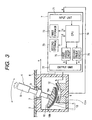
Fig. 3 , the description will be made of a haptic input apparatus according to a second embodiment of the present invention.Fig. 3 is a structural view showing a haptic input apparatus according to the second embodiment. - As shown in
Fig. 3 , the haptic input apparatus according to the present embodiment is characterized by the fact that theelectromagnetic brake 13 is formed of anelectromagnetic coil 5, a permanent magnet 13b arranged below theelectromagnetic coil 5, and amagnetic plate 11 mounted to thespherical portion 3, and that when theelectromagnetic coil 5 is not energized, themagnetic plate 11 is attracted under the action of the permanent magnet 13b and an off-brake type electromagnetic brake for applying an external force to the lever handle 4 is used. As regards other portions, since they are the same as in the haptic input apparatus according to the first embodiment, corresponding portions are designated by the identical reference numerals, and description thereof will be omitted. - The haptic input apparatus according to the present embodiment has similar effects to the haptic input apparatus according to the first embodiment, and in addition, as the
electromagnetic brake 13, an off-brake type electromagnetic brake which applies an external force to the lever handle 4 when not energized has been used. Therefore, only when the lever handle 4 is operated, the electromagnetic coil 13a can be energized, and this leads to the effect that the power consumption of the haptic input apparatus can be reduced. - Next, with reference to
Fig. 4 , the description will be made of a haptic input apparatus according to a third embodiment of the present invention.Fig. 4 is a structural view showing a haptic input apparatus according to the third embodiment. - As shown in
Fig. 4 , the haptic input apparatus according to the present embodiment is characterized by the fact that between the supportingmember 2 and the lever handle 4 of the haptic input apparatus according to the first embodiment, there is provided anelastic member 14 for automatically returning the lever handle 4 to the center position. As regards other portions, since they are the same as in the haptic input apparatus according to the first embodiment, corresponding portions are designated by the identical reference numerals, and description thereof will be omitted. - The haptic input apparatus according to the present embodiment has similar effects to the haptic input apparatus according to the first embodiment, and in addition, since there has been provided the
elastic member 14 for returning to the center, the lever handle 4 can be automatically returned to the center position by means of the elastic force of theelastic member 14 when the operator moves his hands off the lever handle 4. It is possible to obtain a haptic input apparatus with a center returning function in a simple structure. - In this respect, in each of the above-described embodiments, the description has been made of a case where the haptic input apparatus is applied as remote control for an automotive steering system, a gear shift unit, or on-board electric equipment as an example, but the gist of the present invention is not limited thereto and can be applied as remote control for any other unit to be operated.
- As described above, in the haptic input apparatus according to the present invention, since as the actuator, there has been provided a device which is arranged opposite to the end surface of the lever handle and directly applies an external force to the lever handle, it is possible to omit a rotation shaft for converting the rocking motion of the lever handle into the rotary motion, and the link and the like for converting the rocking motion of the lever handle into the linear motion, to simplify the structure of the haptic input apparatus with an operating feeling imparting function equipped with the lever handle, and to miniaturize this sort of haptic input apparatus at low cost.
Claims (5)
- A haptic input apparatus, comprising: a lever handle (4) for an operator to operate manually; a support (2) of the lever handle (4); an actuator (5, 13) arranged opposite to an end surface of the lever handle (4) for directly applying an external force to the lever handle (4); detection means (6) detecting an operating state of the lever handle (4); and control means (7) controlling driving of the actuator (5, 13) on the basis of an output signal from the detection means (6), characterized in that the actuator is an electromagnetic brake (13) made up of a magnetic plate (11) provided on the lower end surface of the lever handle (4), a lining material (12) arranged opposite to the magnetic plate (11), and an electromagnetic coil (5) so as to apply a force to the level handle (4) through the magnetic plate (11).
- The haptic input apparatus according to Claim 1, wherein an amount of rocking and a rocking direction of the lever handle (4) with respect to the support (2) and an amount of rotation and a direction of rotation of the lever handle (4) with respect to the support (2) are detected by the detection means (6), and wherein on the basis of an output signal from the detection means (6) corresponding to the amount of rocking and the rocking direction of the lever handle (4) and the amount of rotation and the direction of rotation, driving of the actuator (5, 13) is controlled.
- The haptic input apparatus according to Claim 1 or 2, wherein between the support (2) and the lever handle (4) there is provided an elastic member (14) for automatically returning the lever handle (4) to a center position set in the support.
- The haptic input apparatus according to any of Claims 1 to 3, wherein as the actuator, there is used an off-brake type electromagnetic brake for applying an external force to the lever handle during non-energization.
- The haptic input apparatus according to any of Claims 1 to 4, wherein as the detection means, there is used a non-contact type optical position sensor for irradiating an end surface of the lever handle with detection light to detect reflected light from the end surface of the lever handle, and for detecting an operating position and an operating direction of the lever handle, and wherein the non-contact type optical position sensor is arranged opposite to the end surface of the lever handle.
Applications Claiming Priority (2)
| Application Number | Priority Date | Filing Date | Title |
|---|---|---|---|
| JP2001332822A JP3934394B2 (en) | 2001-10-30 | 2001-10-30 | Haptic input device |
| JP2001332822 | 2001-10-30 |
Publications (2)
| Publication Number | Publication Date |
|---|---|
| EP1308819A1 EP1308819A1 (en) | 2003-05-07 |
| EP1308819B1 true EP1308819B1 (en) | 2008-10-01 |
Family
ID=19148186
Family Applications (1)
| Application Number | Title | Priority Date | Filing Date |
|---|---|---|---|
| EP02024124A Expired - Lifetime EP1308819B1 (en) | 2001-10-30 | 2002-10-29 | Lever handle type haptic input apparatus equipped with electromagnetic brake |
Country Status (4)
| Country | Link |
|---|---|
| US (1) | US7176892B2 (en) |
| EP (1) | EP1308819B1 (en) |
| JP (1) | JP3934394B2 (en) |
| DE (1) | DE60229101D1 (en) |
Families Citing this family (57)
| Publication number | Priority date | Publication date | Assignee | Title |
|---|---|---|---|---|
| US7084854B1 (en) * | 2000-09-28 | 2006-08-01 | Immersion Corporation | Actuator for providing tactile sensations and device for directional tactile sensations |
| US20040040800A1 (en) * | 2002-07-31 | 2004-03-04 | George Anastas | System and method for providing passive haptic feedback |
| WO2004109488A2 (en) * | 2003-05-30 | 2004-12-16 | Immersion Corporation | System and method for low power haptic feedback |
| JP2004355500A (en) * | 2003-05-30 | 2004-12-16 | Alps Electric Co Ltd | Haptic force feedback input device |
| DE10341466B4 (en) * | 2003-09-05 | 2009-12-03 | Zf Friedrichshafen Ag | ball pin |
| WO2005050846A1 (en) * | 2003-11-20 | 2005-06-02 | Preh Gmbh | Control element |
| US7522152B2 (en) * | 2004-05-27 | 2009-04-21 | Immersion Corporation | Products and processes for providing haptic feedback in resistive interface devices |
| US7198137B2 (en) * | 2004-07-29 | 2007-04-03 | Immersion Corporation | Systems and methods for providing haptic feedback with position sensing |
| US8441433B2 (en) * | 2004-08-11 | 2013-05-14 | Immersion Corporation | Systems and methods for providing friction in a haptic feedback device |
| US9495009B2 (en) * | 2004-08-20 | 2016-11-15 | Immersion Corporation | Systems and methods for providing haptic effects |
| US8013847B2 (en) * | 2004-08-24 | 2011-09-06 | Immersion Corporation | Magnetic actuator for providing haptic feedback |
| US8803796B2 (en) | 2004-08-26 | 2014-08-12 | Immersion Corporation | Products and processes for providing haptic feedback in a user interface |
| US20060049010A1 (en) * | 2004-09-03 | 2006-03-09 | Olien Neil T | Device and method for providing resistive and vibrotactile effects |
| US8002089B2 (en) * | 2004-09-10 | 2011-08-23 | Immersion Corporation | Systems and methods for providing a haptic device |
| US9046922B2 (en) * | 2004-09-20 | 2015-06-02 | Immersion Corporation | Products and processes for providing multimodal feedback in a user interface device |
| US7764268B2 (en) * | 2004-09-24 | 2010-07-27 | Immersion Corporation | Systems and methods for providing a haptic device |
| US7429975B2 (en) * | 2004-11-26 | 2008-09-30 | Sunrex Technology Corp. | Magnetic oscillation metric controller |
| US20100312129A1 (en) | 2005-01-26 | 2010-12-09 | Schecter Stuart O | Cardiovascular haptic handle system |
| US7628700B2 (en) * | 2005-04-13 | 2009-12-08 | Microsoft Corporation | Game controller link mechanism joining a user-activated control and an analogue input device |
| JP4684794B2 (en) * | 2005-08-04 | 2011-05-18 | 富士通コンポーネント株式会社 | Operation device, electronic book apparatus, and electronic apparatus |
| JP4472656B2 (en) * | 2006-03-29 | 2010-06-02 | 国立大学法人静岡大学 | Presentation direction indicator |
| JP4758322B2 (en) * | 2006-06-09 | 2011-08-24 | 株式会社東海理化電機製作所 | Switch device |
| TW200807287A (en) * | 2006-07-21 | 2008-02-01 | Kye Systems Corp | Optical operation input device |
| JP5028931B2 (en) * | 2006-09-28 | 2012-09-19 | ヤマハ株式会社 | Parameter setting device |
| JP4327838B2 (en) * | 2006-12-04 | 2009-09-09 | アルプス電気株式会社 | Combined operation type input device |
| DE102006059822A1 (en) * | 2006-12-11 | 2008-06-12 | Integrated Electronic Systems !Sys Consulting Gmbh | Electric control device |
| JP4499763B2 (en) * | 2007-05-11 | 2010-07-07 | 株式会社コナミデジタルエンタテインメント | Lever unit and game machine |
| US20090195416A1 (en) * | 2008-02-01 | 2009-08-06 | Michael Goren | Input assembly and technique for improved data entry |
| JP5155725B2 (en) * | 2008-04-15 | 2013-03-06 | アルプス電気株式会社 | Multi-directional input device |
| FR2938489B1 (en) * | 2008-11-14 | 2011-08-12 | Peugeot Citroen Automobiles Sa | DEVICE FOR AIDING THE DRIVING OF A VEHICLE |
| DE102009015991A1 (en) * | 2009-04-02 | 2010-10-07 | Pi Ceramic Gmbh Keramische Technologien Und Bauelemente | Device for generating a haptic feedback of a keyless input unit |
| US8542105B2 (en) | 2009-11-24 | 2013-09-24 | Immersion Corporation | Handheld computer interface with haptic feedback |
| JP5471393B2 (en) * | 2009-12-11 | 2014-04-16 | 株式会社日本自動車部品総合研究所 | Input device |
| FR2955679B1 (en) * | 2010-01-25 | 2012-04-06 | Sagem Defense Securite | DEVICE FOR CONTROLLING AN INBOARD EQUIPMENT |
| JP5550433B2 (en) * | 2010-04-22 | 2014-07-16 | 任天堂株式会社 | Operating device and information processing system |
| KR101186483B1 (en) * | 2010-07-12 | 2012-09-27 | 경창산업주식회사 | Shift Lever Assembly Capable of In-Situ Rotation and Linear Movement |
| WO2012080093A1 (en) * | 2010-12-13 | 2012-06-21 | Preh Gmbh | Haptics generation for a push-tilt button |
| US8942828B1 (en) | 2011-04-13 | 2015-01-27 | Stuart Schecter, LLC | Minimally invasive cardiovascular support system with true haptic coupling |
| DE102011082142A1 (en) * | 2011-09-05 | 2013-03-07 | Continental Automotive Gmbh | operating device |
| KR101836499B1 (en) * | 2011-12-02 | 2018-03-09 | 현대자동차주식회사 | Robot handle system of haptic type |
| US10013082B2 (en) | 2012-06-05 | 2018-07-03 | Stuart Schecter, LLC | Operating system with haptic interface for minimally invasive, hand-held surgical instrument |
| WO2014120984A2 (en) * | 2013-01-30 | 2014-08-07 | David Paul Smith | Operator controlled electrical output signal device with variable feel and hold feedback and automated calibration and learnable performance optimization |
| JP5952243B2 (en) * | 2013-09-06 | 2016-07-13 | 株式会社神戸製鋼所 | Force sense operating device |
| KR101511561B1 (en) * | 2013-12-18 | 2015-04-13 | 현대자동차주식회사 | Smart Touch Type Electronic Auto Shift Lever |
| US9242624B2 (en) | 2014-02-11 | 2016-01-26 | Ford Global Technologies, Llc | Electronic parking brake system |
| WO2016079986A1 (en) * | 2014-11-19 | 2016-05-26 | パナソニックIpマネジメント株式会社 | Input/output operation device |
| CN107003725B (en) * | 2014-11-19 | 2020-04-14 | 松下知识产权经营株式会社 | I/O operating device |
| KR101706764B1 (en) * | 2015-02-26 | 2017-02-17 | 주식회사 일진 | Smart Ball Joint |
| KR101774250B1 (en) * | 2016-03-25 | 2017-09-19 | 재단법인 실감교류인체감응솔루션연구단 | Haptic actuator for linear and rotational motion |
| JP6731302B2 (en) * | 2016-07-21 | 2020-07-29 | 川崎重工業株式会社 | Operating device |
| US11609655B2 (en) | 2017-05-24 | 2023-03-21 | Murata Manufacturing Co., Ltd. | Stimulus transmission device |
| DE102017215999A1 (en) * | 2017-09-11 | 2019-03-14 | Continental Automotive Gmbh | Operating device with a tiltable in several directions handle with haptic feedback |
| US20190138046A1 (en) * | 2017-11-07 | 2019-05-09 | Patrick A. McFadden | Array for hemispherical actuation |
| FR3105170B1 (en) * | 2019-12-20 | 2021-11-26 | Safran Electronics & Defense | Cockpit of an aircraft comprising an improved overall reduction ratio and method of using such a handle |
| CN111214827B (en) | 2019-12-30 | 2025-07-22 | 歌尔科技有限公司 | Operating device |
| CN111084982A (en) * | 2019-12-30 | 2020-05-01 | 歌尔科技有限公司 | a manipulation device |
| FR3160389A1 (en) * | 2024-03-25 | 2025-09-26 | Safran Electronics & Defense | Control device, in particular for an aircraft, comprising an integrated force feedback device |
Citations (1)
| Publication number | Priority date | Publication date | Assignee | Title |
|---|---|---|---|---|
| DE19501439A1 (en) * | 1995-01-19 | 1996-09-05 | Meins Juergen Prof Dr Ing | Electromechanical detector of rotation angle for control of vehicle, aircraft or computer input |
Family Cites Families (35)
| Publication number | Priority date | Publication date | Assignee | Title |
|---|---|---|---|---|
| JPS6139425A (en) * | 1984-07-26 | 1986-02-25 | ア−ノルド バ−ド | Steering rod controller |
| FR2575845B1 (en) | 1985-01-07 | 1987-03-27 | Saf Chainette | SHOCK RESISTANT CONTROL MANIPULATOR |
| JPS61198322A (en) * | 1985-02-27 | 1986-09-02 | Nidetsuku:Kk | Joy stick mechanism |
| US4652805A (en) * | 1985-11-04 | 1987-03-24 | Allen-Bradley Company, Inc. | Tactile feedback apparatus for rotary manual input |
| US4777981A (en) * | 1987-05-18 | 1988-10-18 | Commercial Shearing, Inc. | Magnetic detent joy stick and stack remote control valves |
| JPH01288638A (en) * | 1988-05-13 | 1989-11-20 | Hitachi Ltd | Transfer device having emergency brake |
| JPH0615119U (en) * | 1992-07-30 | 1994-02-25 | 栄通信工業株式会社 | Damage prevention structure during operation of the converter |
| JPH0683469A (en) * | 1992-08-29 | 1994-03-25 | Namco Ltd | Operating lever device |
| JPH06200963A (en) * | 1993-01-07 | 1994-07-19 | Hitachi Ltd | Control device for electromagnetic brake |
| US5421694A (en) * | 1993-05-20 | 1995-06-06 | Caterpillar Inc. | Non-contacting joystick |
| US5513100A (en) * | 1993-06-10 | 1996-04-30 | The University Of British Columbia | Velocity controller with force feedback stiffness control |
| US5470615A (en) * | 1994-03-11 | 1995-11-28 | Axis Usa, Inc. | Bonding and coating methods and apparatus for th coils of dynamo-electric machine parts |
| US5532476A (en) * | 1994-12-21 | 1996-07-02 | Mikan; Peter J. | Redundant indicator for detecting neutral position of joystick member |
| US5882206A (en) * | 1995-03-29 | 1999-03-16 | Gillio; Robert G. | Virtual surgery system |
| US5687080A (en) * | 1995-06-20 | 1997-11-11 | Ziba Design, Inc. | Multiple axis data input apparatus and method |
| US6104382A (en) * | 1997-10-31 | 2000-08-15 | Immersion Corporation | Force feedback transmission mechanisms |
| US6437770B1 (en) * | 1998-01-26 | 2002-08-20 | University Of Washington | Flat-coil actuator having coil embedded in linkage |
| JPH11273509A (en) * | 1998-03-25 | 1999-10-08 | Sanwa Denshi Kk | Compound switch |
| US6563487B2 (en) * | 1998-06-23 | 2003-05-13 | Immersion Corporation | Haptic feedback for directional control pads |
| US7038667B1 (en) * | 1998-10-26 | 2006-05-02 | Immersion Corporation | Mechanisms for control knobs and other interface devices |
| US6339419B1 (en) * | 1998-11-10 | 2002-01-15 | Lord Corporation | Magnetically-controllable, semi-active haptic interface system and apparatus |
| US6664666B2 (en) * | 1998-12-23 | 2003-12-16 | Engineering Matters, Inc. | Motor assembly allowing output in multiple degrees of freedom |
| US6781569B1 (en) * | 1999-06-11 | 2004-08-24 | Immersion Corporation | Hand controller |
| JP2000339051A (en) * | 1999-05-26 | 2000-12-08 | Tokai Rika Co Ltd | Joy stick and screen operation system for vehicle |
| US6501458B2 (en) * | 1999-06-30 | 2002-12-31 | Caterpillar Inc | Magnetically coupled input device |
| JP2001175347A (en) * | 1999-12-20 | 2001-06-29 | Mitsumi Electric Co Ltd | Joystick |
| US6822635B2 (en) * | 2000-01-19 | 2004-11-23 | Immersion Corporation | Haptic interface for laptop computers and other portable devices |
| JP2001290594A (en) * | 2000-02-02 | 2001-10-19 | Next:Kk | Lever type operation device |
| US6429849B1 (en) * | 2000-02-29 | 2002-08-06 | Microsoft Corporation | Haptic feedback joystick |
| US6483499B1 (en) * | 2000-04-21 | 2002-11-19 | Hong Kong Productivity Council | 3D sculpturing input device |
| US6641480B2 (en) * | 2001-01-29 | 2003-11-04 | Microsoft Corporation | Force feedback mechanism for gamepad device |
| US6876129B2 (en) * | 2001-09-26 | 2005-04-05 | Mitsuba Corporation | Rotary actuator and method of controlling an actuator |
| JP4589007B2 (en) * | 2002-04-12 | 2010-12-01 | ヘンリー ケイ. オバーマイヤー, | Multi-axis joystick and transducer means therefor |
| US7124648B2 (en) * | 2003-05-19 | 2006-10-24 | Alps Electric Co., Ltd. | Force feedback input device |
| US7319374B2 (en) * | 2004-04-14 | 2008-01-15 | Immersion Corporation | Moving magnet actuator |
-
2001
- 2001-10-30 JP JP2001332822A patent/JP3934394B2/en not_active Expired - Fee Related
-
2002
- 2002-10-29 EP EP02024124A patent/EP1308819B1/en not_active Expired - Lifetime
- 2002-10-29 DE DE60229101T patent/DE60229101D1/en not_active Expired - Fee Related
- 2002-10-29 US US10/283,593 patent/US7176892B2/en not_active Expired - Fee Related
Patent Citations (1)
| Publication number | Priority date | Publication date | Assignee | Title |
|---|---|---|---|---|
| DE19501439A1 (en) * | 1995-01-19 | 1996-09-05 | Meins Juergen Prof Dr Ing | Electromechanical detector of rotation angle for control of vehicle, aircraft or computer input |
Also Published As
| Publication number | Publication date |
|---|---|
| JP3934394B2 (en) | 2007-06-20 |
| US7176892B2 (en) | 2007-02-13 |
| US20030080939A1 (en) | 2003-05-01 |
| DE60229101D1 (en) | 2008-11-13 |
| JP2003140757A (en) | 2003-05-16 |
| EP1308819A1 (en) | 2003-05-07 |
Similar Documents
| Publication | Publication Date | Title |
|---|---|---|
| EP1308819B1 (en) | Lever handle type haptic input apparatus equipped with electromagnetic brake | |
| KR100416717B1 (en) | Input device mounted on vehicle | |
| US6859198B2 (en) | Force feedback functioning manual input device and onboard instrument control system having it | |
| EP1471551B1 (en) | Stalk switch | |
| JP5144621B2 (en) | Haptic transmission | |
| US6591175B2 (en) | Manual input device with force feedback function and vehicle-mounted equipment controller using same | |
| US6694236B2 (en) | Vehicle-mounted device control unit | |
| US6987508B2 (en) | Manual input device which provides its control knob with plural modes of operation feeling, and car-mounted apparatus controller based thereon | |
| EP1220073A2 (en) | Manual input device improved in operatability and multifunctionality, and vehicle-mounted control device using it | |
| JP2002062944A (en) | On-vehicle input device | |
| KR100349212B1 (en) | Input device mounted on vehicle | |
| JP2002189556A (en) | Manual input device and on-vehicle equipment controller using the same | |
| JP2002189560A (en) | Manual input device and on-vehicle equipment controller using the same | |
| JP2001028221A (en) | On-vehicle input device | |
| JP3814104B2 (en) | In-vehicle input device | |
| JP4624973B2 (en) | Shift device | |
| JP2002196866A (en) | Manual input device and on-vehicle equipment controller using the manual input device | |
| JP2000149719A (en) | On-vehicle input device | |
| US6937927B2 (en) | Method and apparatus for human vehicle interface | |
| CN101189418A (en) | Throttle control method and device |
Legal Events
| Date | Code | Title | Description |
|---|---|---|---|
| PUAI | Public reference made under article 153(3) epc to a published international application that has entered the european phase |
Free format text: ORIGINAL CODE: 0009012 |
|
| AK | Designated contracting states |
Designated state(s): AT BE BG CH CY CZ DE DK EE ES FI FR GB GR IE IT LI LU MC NL PT SE SK TR |
|
| AX | Request for extension of the european patent |
Extension state: AL LT LV MK RO SI |
|
| 17P | Request for examination filed |
Effective date: 20030516 |
|
| AKX | Designation fees paid |
Designated state(s): DE FR GB |
|
| GRAP | Despatch of communication of intention to grant a patent |
Free format text: ORIGINAL CODE: EPIDOSNIGR1 |
|
| GRAS | Grant fee paid |
Free format text: ORIGINAL CODE: EPIDOSNIGR3 |
|
| GRAA | (expected) grant |
Free format text: ORIGINAL CODE: 0009210 |
|
| AK | Designated contracting states |
Kind code of ref document: B1 Designated state(s): DE FR GB |
|
| REG | Reference to a national code |
Ref country code: GB Ref legal event code: FG4D |
|
| REF | Corresponds to: |
Ref document number: 60229101 Country of ref document: DE Date of ref document: 20081113 Kind code of ref document: P |
|
| PGFP | Annual fee paid to national office [announced via postgrant information from national office to epo] |
Ref country code: DE Payment date: 20081127 Year of fee payment: 7 |
|
| PLBE | No opposition filed within time limit |
Free format text: ORIGINAL CODE: 0009261 |
|
| STAA | Information on the status of an ep patent application or granted ep patent |
Free format text: STATUS: NO OPPOSITION FILED WITHIN TIME LIMIT |
|
| 26N | No opposition filed |
Effective date: 20090702 |
|
| GBPC | Gb: european patent ceased through non-payment of renewal fee |
Effective date: 20090101 |
|
| REG | Reference to a national code |
Ref country code: FR Ref legal event code: ST Effective date: 20090831 |
|
| PG25 | Lapsed in a contracting state [announced via postgrant information from national office to epo] |
Ref country code: GB Free format text: LAPSE BECAUSE OF NON-PAYMENT OF DUE FEES Effective date: 20090101 |
|
| PG25 | Lapsed in a contracting state [announced via postgrant information from national office to epo] |
Ref country code: DE Free format text: LAPSE BECAUSE OF NON-PAYMENT OF DUE FEES Effective date: 20100501 |
|
| PG25 | Lapsed in a contracting state [announced via postgrant information from national office to epo] |
Ref country code: FR Free format text: LAPSE BECAUSE OF NON-PAYMENT OF DUE FEES Effective date: 20081031 |