EP0914561B1 - Piston pump with a pipe segment as a bushing - Google Patents
Piston pump with a pipe segment as a bushing Download PDFInfo
- Publication number
- EP0914561B1 EP0914561B1 EP98919061A EP98919061A EP0914561B1 EP 0914561 B1 EP0914561 B1 EP 0914561B1 EP 98919061 A EP98919061 A EP 98919061A EP 98919061 A EP98919061 A EP 98919061A EP 0914561 B1 EP0914561 B1 EP 0914561B1
- Authority
- EP
- European Patent Office
- Prior art keywords
- bushing
- piston pump
- cylinder bore
- piston
- liner
- Prior art date
- Legal status (The legal status is an assumption and is not a legal conclusion. Google has not performed a legal analysis and makes no representation as to the accuracy of the status listed.)
- Expired - Lifetime
Links
- 238000007789 sealing Methods 0.000 claims description 30
- 238000006073 displacement reaction Methods 0.000 claims description 12
- 230000000295 complement effect Effects 0.000 claims description 6
- 230000002093 peripheral effect Effects 0.000 claims 3
- 239000011324 bead Substances 0.000 description 4
- 238000003825 pressing Methods 0.000 description 4
- 239000012530 fluid Substances 0.000 description 3
- 239000000463 material Substances 0.000 description 3
- 230000001154 acute effect Effects 0.000 description 2
- 238000000034 method Methods 0.000 description 2
- 229910000831 Steel Inorganic materials 0.000 description 1
- 230000001133 acceleration Effects 0.000 description 1
- 239000000853 adhesive Substances 0.000 description 1
- 230000001070 adhesive effect Effects 0.000 description 1
- 229910052782 aluminium Inorganic materials 0.000 description 1
- XAGFODPZIPBFFR-UHFFFAOYSA-N aluminium Chemical compound [Al] XAGFODPZIPBFFR-UHFFFAOYSA-N 0.000 description 1
- 230000000994 depressogenic effect Effects 0.000 description 1
- 238000011161 development Methods 0.000 description 1
- 230000018109 developmental process Effects 0.000 description 1
- 238000005516 engineering process Methods 0.000 description 1
- 239000012634 fragment Substances 0.000 description 1
- 238000003780 insertion Methods 0.000 description 1
- 230000037431 insertion Effects 0.000 description 1
- 238000003754 machining Methods 0.000 description 1
- 238000004519 manufacturing process Methods 0.000 description 1
- 229910052751 metal Inorganic materials 0.000 description 1
- 239000002184 metal Substances 0.000 description 1
- 239000000565 sealant Substances 0.000 description 1
- 238000000926 separation method Methods 0.000 description 1
- 238000009987 spinning Methods 0.000 description 1
- 239000010959 steel Substances 0.000 description 1
- 238000007514 turning Methods 0.000 description 1
Images


Classifications
-
- F—MECHANICAL ENGINEERING; LIGHTING; HEATING; WEAPONS; BLASTING
- F04—POSITIVE - DISPLACEMENT MACHINES FOR LIQUIDS; PUMPS FOR LIQUIDS OR ELASTIC FLUIDS
- F04B—POSITIVE-DISPLACEMENT MACHINES FOR LIQUIDS; PUMPS
- F04B53/00—Component parts, details or accessories not provided for in, or of interest apart from, groups F04B1/00 - F04B23/00 or F04B39/00 - F04B47/00
- F04B53/16—Casings; Cylinders; Cylinder liners or heads; Fluid connections
-
- B—PERFORMING OPERATIONS; TRANSPORTING
- B60—VEHICLES IN GENERAL
- B60T—VEHICLE BRAKE CONTROL SYSTEMS OR PARTS THEREOF; BRAKE CONTROL SYSTEMS OR PARTS THEREOF, IN GENERAL; ARRANGEMENT OF BRAKING ELEMENTS ON VEHICLES IN GENERAL; PORTABLE DEVICES FOR PREVENTING UNWANTED MOVEMENT OF VEHICLES; VEHICLE MODIFICATIONS TO FACILITATE COOLING OF BRAKES
- B60T8/00—Arrangements for adjusting wheel-braking force to meet varying vehicular or ground-surface conditions, e.g. limiting or varying distribution of braking force
- B60T8/32—Arrangements for adjusting wheel-braking force to meet varying vehicular or ground-surface conditions, e.g. limiting or varying distribution of braking force responsive to a speed condition, e.g. acceleration or deceleration
- B60T8/34—Arrangements for adjusting wheel-braking force to meet varying vehicular or ground-surface conditions, e.g. limiting or varying distribution of braking force responsive to a speed condition, e.g. acceleration or deceleration having a fluid pressure regulator responsive to a speed condition
- B60T8/40—Arrangements for adjusting wheel-braking force to meet varying vehicular or ground-surface conditions, e.g. limiting or varying distribution of braking force responsive to a speed condition, e.g. acceleration or deceleration having a fluid pressure regulator responsive to a speed condition comprising an additional fluid circuit including fluid pressurising means for modifying the pressure of the braking fluid, e.g. including wheel driven pumps for detecting a speed condition, or pumps which are controlled by means independent of the braking system
- B60T8/4031—Pump units characterised by their construction or mounting
-
- F—MECHANICAL ENGINEERING; LIGHTING; HEATING; WEAPONS; BLASTING
- F04—POSITIVE - DISPLACEMENT MACHINES FOR LIQUIDS; PUMPS FOR LIQUIDS OR ELASTIC FLUIDS
- F04B—POSITIVE-DISPLACEMENT MACHINES FOR LIQUIDS; PUMPS
- F04B53/00—Component parts, details or accessories not provided for in, or of interest apart from, groups F04B1/00 - F04B23/00 or F04B39/00 - F04B47/00
- F04B53/16—Casings; Cylinders; Cylinder liners or heads; Fluid connections
- F04B53/162—Adaptations of cylinders
- F04B53/166—Cylinder liners
- F04B53/168—Mounting of cylinder liners in cylinders
Definitions
- the invention relates to a piston pump with the features of the preamble of claim 1.
- Piston pump Such a piston pump is already known for example from US 1,592,266 A.
- This well-known Piston pump comprises a piston which can be driven to a reciprocating stroke movement and which is in a tubular liner is axially slidably received.
- the liner is at a radial distance in anchored to a cylinder. This is done axially on the outer circumference of the liner preloadable holding element.
- the holding element fixes the liner in the cylinder and causes on the other hand, a seal between the outside of the liner and the inside of the cylinder wall.
- the two The ends of the liner are open to separate pressure chambers.
- Piston pumps in particular for use as pumps for a vehicle brake system with a Anti-lock, traction, driving dynamics control device and / or for a power brake system of a motor vehicle are provided, for example, from DE 40 27 794 A1 and from DE 44 07 978 A1 known.
- These piston pumps have a pump housing into which a liner is immovable is used, in which a piston is axially displaceably received.
- This liner of the well-known Piston pumps have a blind hole in the form of a stepped bore for receiving a piston and one Exhaust valve on. An outside of the liner is with a number of grooves, undercuts and steps, for example for inserting sealing rings or as a stop surface.
- the Liner is a turned part, the production of which is complex and expensive due to its inner and outer shape is in the making. Another disadvantage is that the liner after machining must be hardened to keep their wear and tear when operating the piston pump low and to achieve a sufficient service life in this way.
- the piston pump according to the invention with the features of claim 1 has a Closing the cylinder bore outwards and projecting into the interior of the liner Element on. This element simultaneously fixes the liner in position Closure of the cylinder bore and separation of the suction side from the pressure side of the Piston pump realized. Because of the transfer of these different functions to one The only element is that components and assembly effort are saved.
- the object on which the present invention is based is accordingly that of a To create a piston pump with fewer components.
- a piston pump solves this task the features of claim 1.
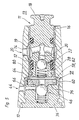
- FIG. 1 shows an axial section of a piston pump according to the invention
- Figure 2 shows a detail of a modified embodiment of the invention according to Arrow II in Figure 1
- Figure 3 shows an axial section of a second embodiment of the invention
- Figure 4 shows a detail according to arrow IV in Figure 3
- Figure 5 shows an axial section of a third embodiment of the invention
- Figure 6 is a detail view according to arrow VI in Figure 5 on a larger scale
- Figure 7 is a detail view according to arrow VII in Figure 6 on a larger scale.
- the piston pump according to the invention shown in FIG. 1 is in particular as a return pump in a brake system Vehicle provided with a wheel slip control.
- Wheel slip control can, for example, block the Wheels of the vehicle during a braking process and / or a Spinning the driven wheels of the vehicle in strong Acceleration can be prevented.
- the piston pump according to the invention has a pump housing 10 a hydraulic block, in which other than the piston pump Return pump for a slip-controlled vehicle brake system other hydraulic components, not shown, for Slip control used and hydraulic with each other and are connected to the piston pump. From which the Pump housing 10 forming hydraulic block is in the Drawing only one of the essential parts of the invention Shown piston pump-showing fragment.
- the Piston pump comprises one or more, preferably two, in the pump housing 10 received pump elements 11. Der For the sake of clarity, there is only one pump element 11 shown.
- the pump housing 10 encloses an interior 13, in which an eccentric drive, not shown, is provided is.
- graduated cylinder bore 12 of the pump housing 10 is a piece of pipe as Liner 14 used, in which a piston 16 axially is slidably received.
- an inner diameter of cylinder bore 12 larger than an outer diameter of the liner 14, so that in this area between the liner 14 and the Pump housing 10 a radial distance 19 remains free.
- the piston pump has a pump inlet 20.
- the pump inlet 20 essentially belong in the pump housing 10 attached inlet channel 20a, the radial distance 19, a through the wall of the liner 14 transverse bore 20b, , a recess 20c provided on the outer circumference of the piston 16 and at least one recess 20c with one in the piston 16 attached, connecting axial step bore 20e Cross hole 20d.
- Stepped bore 20e of the piston 16 is a spring-loaded Ball check valve used as an inlet valve 22, the Valve closing spring 24 is supported on a sheet metal cap 26, the end face facing a displacement space 28 the piston 16 is attached and fastened by flanging.
- this can Inlet valve 22 instead of in the piston 16 also in the inlet channel 20a of the pump housing 10 may be provided.
- a leadership gap between the displaceable piston 16 and the liner 14 is sealed with two O-rings as sealing rings 30, 31.
- One of the two sealing rings 30 separates the pump inlet 20 from the displacement space 28, the other sealing ring 31 separates the Pump inlet 20 from the interior 13 of the pump housing 10.
- Liner 14 has a conical widening 32 which a complementary extension 34 of the cylinder bore 12 is applied.
- the liner 14 is with its conical widening as a deep-drawn part similar to a cup or the like manufactured. It can be hardened after deep drawing.
- the plug shows a circumferential, outwardly projecting radial flange 35 with a sharp-edged cross section on the piston 16 facing away from outside.
- This radial flange 35 from Steel deformed by turning the sealing plug that of softer material, for example Die-cast aluminum, existing pump housing 10 plastically in a circumferential annular groove 37 of the sealing plug into it directly on a side facing the piston 16 the radial flange 35 connects when the plug with sufficient force axially against it Pump housing is pressed.
- the plastic deformation of the Material of the pump housing 10 in the annular groove 37 of the Sealing plug ensures a secure seal between the plug and pump housing 10 and a large one Holding force.
- the plug forms a fastener 36 for the liner 14. It has a 32 for expansion Liner 14 complementary cone 38 in the Expansion 32 lies and this outwards against the Extension 34 of the cylinder bore 12 presses. This is the Liner 14 fixed in the pump housing 10 and on her the Displacement 28 enclosing end against both Pump housing 10 and against the fastener 36 sealed.
- the cone 38 of the Fastener 36 an axial ring step 39 and the Extension 34 of the cylinder bore 12 a complementary Counter stage in which the ring stage 39 of the fastener the expansion 32 of the liner 14 elastic / plastic into deformed.
- the piston pump has a pump outlet 44.
- the pump outlet 44 essentially includes one in fastener 36 made coaxial blind bore 44a, one on the outer circumference of the fastening element 36 provided circumferential recess 44c, at least one the blind bore 44a with the recess 44c connecting transverse bore 44b and one in the pump housing 10 provided, from the recess 44c to a not shown High pressure connection leading outlet duct 44d.
- the pump housing has on the side of the head 18 of the piston 16 10 one or more, preferably two rotating, flat and wide, protruding into the cylinder bore 12 Seal shafts 42.
- Seal shafts 42 In these sealing shafts 42 Bushing 14 used sealingly by a press fit. Due to the interference fit between the radially inward protruding shaft tips of the sealing shafts 42 and the The outer circumference of the liner 14 becomes an inadmissible Leakage connection for the pumped by the piston pump Fluid between the pump inlet 20 and the interior 13 prevented.
- the cylinder bore 12 has a clearance fit to the liner 14 on, d. H. in the middle area of the liner 14 between the liner 14 and the pump housing 10 of the Radial distance 19, so that the liner 14 with less Force to insert into the cylinder bore 12 what in particular damage to the liner 14 when inserted avoids. Because the pressure between the crests of the Sealing shafts 42 and the outer circumference of the liner 14, in Viewed in the longitudinal direction of the pump element 11, only very briefly is, the insertion of the liner 14 in the pump housing 10 by the pressure in the area of the sealing shafts 42 only marginally disabled.
- the fastening element 36 has the coaxial blind bore 44a on, which connects to the displacement space 28.
- a spring-loaded ball check valve used as an outlet valve 46.
- An annular valve seat body 48 of the outlet valve 46 is in a mouth of the Blind bore 44a inserted and by caulking (reference number 50) attached.
- Piston pump has a cylindrical expansion 52 its end enclosing the displacement space 28, into the the fastener 36 with a molded cylindrical portion 54 engages.
- the diameter of the cylindrical portion 54, the wall thickness of the liner 14th and a diameter of the cylinder bore 12 are so on top of each other voted that an interference fit between the cylindrical portion 54 and the cylindrical expansion 52 and between the cylindrical expansion 52 and the There is a cylindrical bore 12 in the pump housing 10, i.e. the cylindrical portion 54 of the fastener 36 presses the liner 14 against its cylindrical expansion 52 against a wall of the cylinder bore 12.
- the liner 14 is first on the Fastener 36 pressed, the cylindrical Widening 52 of the liner 14 is elastically expanded.
- the elastically widened expansion 52 of the liner 14 has an interference fit causing the press fit Cylinder bore 12.
- This liner 14 in Pump housing 10 fixed and there is a seal between the liner 14 and the pump housing 10 and the Fastener 36 causes.
- the cylindrical portion 54 of the fastener 36 points before inserting the fastener 36 into the Cylinder bore 12 has a circumferential sealing bead 40 (FIG 4) which when pressing the cylinder section 54 into the Widening 52 of the liner 14 elastic and / or plastic is deformed. Since the liner 14 outside the cylinder bore 12 is pressed onto the fastening element 36, the sealing bead 40 expands the bush 14 or is from the liner 14 depressed while the liner 14 together with the fastener 36 in the Cylinder bore 12 is installed so that it is not sheared off becomes.
- a piece of pipe can be hollow cylindrical Cross-section, i.e. without expansion, as a liner 14 Find the use with the fastener 36 in the same manner as described above and in FIG. 3 shown fixed in the pump housing 10 in the axial direction and is sealed (not shown).
- Piston pump goes to the displacement space 28 enclosing end with a ring step 58 in one cylindrical expansion 60 over.
- valve seat part 64 takes place on a circumferential outer edge 74 of the Valve seat part 64, with which the valve seat part 64 on a The inside of the ring step 58 of the liner 14 rests.
- valve seat part 64 lies in a cylindrical recess 76 in an end face of the piston 16 Fastener 36. Since the fastener 36 the Valve seat part 64 in the axial direction against the ring step 58 the liner 14 presses, the valve seat member 64 is in the Recess 76 of the fastener 36 fixed without it a caulking (see reference number 50 in Figure 1) or another fastening measure is required.
- valve seat part 64 A seal between valve seat part 64 and fastener 36 takes place on a circumferential outer edge 78 of the Valve seat part 64, with which this on a base 80 of Recess 76 abuts ( Figure 6).
- the base 80 gives way to the Recess 76 of the fastener 36 and / or one of the Base 80 facing end face 82 of the valve seat part 64 by an acute angle ⁇ from an imaginary radial surface from.
- FIG. 5 is according to the invention Piston pump consistent with that shown in Figure 1 Piston pump built and works in the same way. It In this respect, reference is made to the corresponding statements relating to FIG. 1 directed.
Landscapes
- Engineering & Computer Science (AREA)
- Mechanical Engineering (AREA)
- Physics & Mathematics (AREA)
- Fluid Mechanics (AREA)
- General Engineering & Computer Science (AREA)
- Transportation (AREA)
- Details Of Reciprocating Pumps (AREA)
- Reciprocating Pumps (AREA)
Description
Die Erfindung betrifft eine Kolbenpumpe mit den Merkmalen des Oberbegriffs des Anspruchs 1.The invention relates to a piston pump with the features of the preamble of claim 1.
Eine derartige Kolbenpumpe ist beispielsweise aus der US 1,592,266 A bereits bekannt. Diese bekannte Kolbenpumpe umfasst einen zu einer hin- und hergehenden Hubbewegung antreibbaren Kolben, der in einer rohrförmigen Laufbuchse axial verschieblich aufgenommen ist. Die Laufbuchse ist mit radialem Abstand in einem Zylinder verankert. Dazu dient ein am Außenumfang der Laufbuchse angeordnetes, axial vorspannbares Haltelement. Das Haltelement fixiert zum einen die Laufbuchse im Zylinder und bewirkt zum anderen eine Abdichtung zwischen Laufbuchsenaußenseite und Zylinderwandinnenseite. Die beiden Enden der Laufbuchse sind zu getrennten Druckkammern hin offen.Such a piston pump is already known for example from US 1,592,266 A. This well-known Piston pump comprises a piston which can be driven to a reciprocating stroke movement and which is in a tubular liner is axially slidably received. The liner is at a radial distance in anchored to a cylinder. This is done axially on the outer circumference of the liner preloadable holding element. The holding element fixes the liner in the cylinder and causes on the other hand, a seal between the outside of the liner and the inside of the cylinder wall. The two The ends of the liner are open to separate pressure chambers.
Kolbenpumpen, die insbesondere zur Verwendung als Pumpen für eine Fahrzeugbremsanlage mit einer
Blockierschutz-, Antriebsschlupf-, Fahrdynamikregeleinrichtung und/oder für eine Fremdkraftbremsanlage
eines Kraftfahrzeugs vorgesehen sind, sind beispielhaft aus der DE 40 27 794 A1 und aus der DE 44 07 978
A1 bekannt. Diese Kolbenpumpen weisen ein Pumpengehäuse auf, in das eine Laufbuchse unbeweglich
eingesetzt ist, in der ein Kolben axial verschieblich aufgenommen ist. Diese Laufbuchse der bekannten
Kolbenpumpen weist ein Sackloch in Form einer Stufenbohrung zur Aufnahme eines Kolbens und eines
Auslassventils auf. Eine Außenseite der Laufbuchse ist mit einer Anzahl von Nuten, Hinterschneidungen
und Stufen, beispielsweise zum Einlegen von Dichtringen oder als Anschlagfläche, vorgesehen. Die
Laufbuchse ist ein Drehteil, dessen Herstellung aufgrund seiner Innen- und Außenform aufwändig und teuer
in der Herstellung ist. Weiterer Nachteil ist, dass die Laufbuchse nach der spanenden Bearbeitung
gehärtet werden muss, um ihren Verschleiß beim Betrieb der Kolbenpumpe niedrig zu halten
und auf diese Weise eine ausreichende Standzeit zu erzielen.Piston pumps, in particular for use as pumps for a vehicle brake system with a
Anti-lock, traction, driving dynamics control device and / or for a power brake system
of a motor vehicle are provided, for example, from
Die erfindungsgemäße Kolbenpumpe mit den Merkmalen des Anspruchs 1 weist ein die Zylinderbohrung nach außen verschließendes und in das Innere der Laufbuchse hineinragendes Element auf. Mit diesem Element wird gleichzeitig eine Lagefixierung der Laufbuchse, ein Verschluss der Zylinderbohrung und eine Trennung der Saugseite von der Druckseite der Kolbenpumpe realisiert. Aufgrund der Übertragung dieser unterschiedlichen Funktionen auf ein einziges Element werden Bauteile und Montageaufwand eingespart.The piston pump according to the invention with the features of claim 1 has a Closing the cylinder bore outwards and projecting into the interior of the liner Element on. This element simultaneously fixes the liner in position Closure of the cylinder bore and separation of the suction side from the pressure side of the Piston pump realized. Because of the transfer of these different functions to one The only element is that components and assembly effort are saved.
Die der vorliegenden Erfindung zugrundeliegende Aufgabe besteht demnach darin, eine Kolbenpumpe mit weniger Bauteilen zu schaffen. Diese Aufgabe löst eine Kolbenpumpe mit den Merkmalen des Anspruchs 1.The object on which the present invention is based is accordingly that of a To create a piston pump with fewer components. A piston pump solves this task the features of claim 1.
Die Unteransprüche haben vorteilhafte Ausgestaltungen und Weiterbildungen der erfindungsgemäßen Kolbenpumpe zum Gegenstand.The subclaims have advantageous refinements and developments of Piston pump according to the invention.
Die Erfindung wird nachfolgend anhand in der Zeichnung dargestellter Ausführungsbeispiele näher erläutert. Es zeigen Figur 1 einen Achsschnitt einer erfindungsgemäßen Kolbenpumpe, Figur 2 eine Einzelheitdarstellung einer abgewandelten Ausführungsform der Erfindung gemäß Pfeil II in Figur 1, Figur 3 einen Achsschnitt einer zweiten Ausführungsform der Erfindung, Figur 4 eine Einzelheitdarstellung gemäß Pfeil IV in Figur 3, Figur 5 einen Achsschnitt einer dritten Ausführungsform der Erfindung, Figur 6 eine Einzelheitdarstellung gemäß Pfeil VI in Figur 5 in größerem Maßstab und Figur 7 eine Einzelheitdarstellung gemäß Pfeil VII in Figur 6 in größerem Maßstab. The invention is described below with reference to exemplary embodiments shown in the drawing explained in more detail. 1 shows an axial section of a piston pump according to the invention, Figure 2 shows a detail of a modified embodiment of the invention according to Arrow II in Figure 1, Figure 3 shows an axial section of a second embodiment of the invention, Figure 4 shows a detail according to arrow IV in Figure 3, Figure 5 shows an axial section of a third embodiment of the invention, Figure 6 is a detail view according to arrow VI in Figure 5 on a larger scale and Figure 7 is a detail view according to arrow VII in Figure 6 on a larger scale.
Die in Figur 1 dargestellte, erfindungsgemäße Kolbenpumpe ist insbesondere als Rückförderpumpe in einer Bremsanlage eines Fahrzeugs mit einer Radschlupfregelung vorgesehen. Mit der Radschlupfregelung kann beispielsweise ein Blockieren der Räder des Fahrzeugs während eines Bremsvorgans und/oder ein Durchdrehen der angetriebenen Räder des Fahrzeugs bei starkem Beschleunigen verhindert werden.The piston pump according to the invention shown in FIG. 1 is in particular as a return pump in a brake system Vehicle provided with a wheel slip control. With the Wheel slip control can, for example, block the Wheels of the vehicle during a braking process and / or a Spinning the driven wheels of the vehicle in strong Acceleration can be prevented.
Die erfindungsgemäße Kolbenpumpe weist als Pumpengehäuse 10
einen Hydraulikblock auf, in den außer der Kolbenpumpe als
Rückförderpumpe für eine schlupfgeregelte Fahrzeugbremsanlage
weitere, nicht dargestellte hydraulische Baukomponenten zur
Schlupfregelung eingesetzt und hydraulisch miteinander und
mit der Kolbenpumpe verschaltet sind. Von dem das
Pumpengehäuse 10 bildenden Hydraulikblock ist in der
Zeichnung nur ein die wesentlichen Teile der erfindungsgemäßen
Kolbenpumpe zeigendes Bruchstück dargestellt. Die
Kolbenpumpe umfaßt ein oder mehrere, vorzugsweise zwei, in
dem Pumpengehäuse 10 aufgenommene Pumpenelemente 11. Der
besseren Übersichtlichkeit wegen ist nur ein Pumpenelement 11
dargestellt. Das Pumpengehäuse 10 umschließt einen Innenraum
13, in dem ein nicht dargestellter Exzenterantrieb vorgesehen
ist.The piston pump according to the invention has a pump housing 10
a hydraulic block, in which other than the piston pump
Return pump for a slip-controlled vehicle brake system
other hydraulic components, not shown, for
Slip control used and hydraulic with each other and
are connected to the piston pump. From which the
Pump housing 10 forming hydraulic block is in the
Drawing only one of the essential parts of the invention
Shown piston pump-showing fragment. The
Piston pump comprises one or more, preferably two, in
the
In eine von einer Außenseite des Pumpengehäuses 10 bis in den
Innenraum 13 verlaufende, abgestuft ausgeführte Zylinderbohrung
12 des Pumpengehäuses 10 ist ein Rohrstück als
Laufbuchse 14 eingesetzt, in der ein Kolben 16 axial
verschieblich aufgenommen ist. Ein Kopf 18 des Kolbens 16,
der zum Antreiben des Kolbens 16 zu einer hin- und
hergehenden Hubbewegung in an sich bekannter Weise mittels
des nicht dargestellten Exzenterantriebs vorgesehen ist,
steht auf einer Seite in den Innenraum 13 des Pumpengehäuses
10 vor. In einem Bereich zwischen den beiden Enden der
Laufbuchse 14 ist ein Innendurchmesser der Zylinderbohrung 12
größer als ein Außendurchmesser der Laufbuchse 14, so daß in
diesem Bereich zwischen der Laufbuchse 14 und dem
Pumpengehäuse 10 ein Radialabstand 19 frei bleibt.In one of an outside of the
Die Kolbenpumpe hat einen Pumpeneinlaß 20. Zum Pumpeneinlaß
20 gehören im wesentlichen ein in dem Pumpengehäuse 10
angebrachter Einlaßkanal 20a, der Radialabstand 19, eine
durch die Wandung der Laufbuchse 14 führende Querbohrung 20b,
. ein am Außenumfang des Kolbens 16 vorgesehener Einstich 20c
und mindestens eine den Einsich 20c mit einer im Kolben 16
angebrachten, axialen Stufenbohrung 20e verbindende
Querbohrung 20d. In die zum Pumpeneinlaß 20 gehörende axiale
Stufenbohrung 20e des Kolbens 16 ist ein federbelastetes
Kugelrückschlagventil als Einlaßventil 22 eingesetzt, dessen
Ventilschließfeder 24 sich an einer Blechkappe 26 abstützt,
die auf eine einem Verdrängungsraum 28 zugewandte Stirnseite
des Kolbens 16 aufgesetzt und durch Umbördeln befestigt ist.The piston pump has a
In Abweichung zum dargestellten Ausführungsbeispiel kann das
Einlaßventil 22 anstatt im Kolben 16 auch in dem Einlaßkanal
20a des Pumpengehäuses 10 vorgesehen sein. Ein Führungsspalt
zwischen dem verschiebbaren Kolben 16 und der Laufbuchse 14
ist mit zwei O-Ringen als Dichtringe 30, 31 abgedichtet.
Einer der beiden Dichtringe 30 trennt den Pumpeneinlaß 20 von
dem Verdrängungsraum 28, der andere Dichtring 31 trennt den
Pumpeneinlaß 20 vom Innenraum 13 des Pumpengehäuses 10.In deviation from the illustrated embodiment, this can
Ein die Verdrängungskammer 28 umschließendes Ende der
Laufbuchse 14 weist eine konische Aufweitung 32 auf, die an
einer komplementären Erweiterung 34 der Zylinderbohrung 12
anliegt. Die Laufbuchse 14 mit ihrer konischen Aufweitung ist
als Tiefziehteil ähnlich wie ein Becher oder dgl.
hergestellt. Sie kann nach dem Tiefziehen gehärtet werden.An end enclosing the
Zum Verschluß der Zylinderbohrung 12 auf der Seite des
Verdrängungsraums 28 ist ein Verschlußstopfen in sog. Self-Clinch-Technik
in die Zylinderbohrung 12 fest eingesetzt.
Self-Clinch bedeutet ein durch Einpressen des Verschlußstopfens
bewirktes Verstemmen: Der Verschlußstopfen weist
einen umlaufenden, nach außen überstehenden Radialflansch 35
mit scharfkantigem Querschnitt an seiner dem Kolben 16
abgewandten Außenseite auf. Dieser Radialflansch 35 des aus
Stahl durch Drehen hergestellten Verschlußstopfens verformt
das aus weicherem Werkstoff, beispielsweise
Aluminiumdruckguß, bestehende Pumpengehäuse 10 plastisch in
eine umlaufende Ringnut 37 des Verschlußstopfens hinein, die
sich auf einer dem Kolben 16 zugewandten Seite unmittelbar an
den Radialflansch 35 anschließt, wenn der Verschlußstopfen
mit ausreichend großer Kraft axial gegen das
Pumpengehäuse gedrückt wird. Die plastische Verformung des
Werkstoffs des Pumpengehäuses 10 in die Ringnut 37 des
Verschlußstopfens hinein bewirkt eine sichere Abdichtung
zwischen Verschlußstopfen und Pumpengehäuse 10 und eine große
Haltekraft.To close the cylinder bore 12 on the side of the
Der Verschlußstopfen bildet ein Befestigungselement 36 für
die Laufbuchse 14. Er weist einen zur Aufweitung 32 der
Laufbuchse 14 komplementären Konus 38 auf, der in der
Aufweitung 32 einliegt und diese nach außen gegen die
Erweiterung 34 der Zylinderbohrung 12 drückt. Dadurch ist die
Laufbuchse 14 im Pumpengehäuse 10 fixiert und an ihrem den
Verdrängungsraum 28 umschließenden Ende sowohl gegen das
Pumpengehäuse 10 als auch gegen das Befestigungselement 36
abgedichtet. Zur sicheren Abdichtung weist der Konus 38 des
Befestigungselements 36 eine axiale Ringstufe 39 und die
Erweiterung 34 der Zylinderbohrung 12 eine komplementäre
Gegenstufe auf, in die die Ringstufe 39 des Befestigungselements
die Aufweitung 32 der Laufbuchse 14 elastisch/plastisch
hineinverformt.The plug forms a
Eine weitere Möglichkeit zur sicheren Abdichtung ist den
Konus 38 des Befestigungselements 36 mit einem umlaufenden
Dichtwulst 40 vorzusehen, wie er in Figur 2 dargestellt ist,
der sich beim Einsetzen des Befestigungselements 36 in die
Zylinderbohrung 12 durch Andrücken an die Aufweitung 32 der
Zylinderbuchse 14 elastisch und/oder plastisch verformt. Die
Werkstoffe von Laufbuchse 14 und Befestigungselement 36 haben
in etwa die gleiche Härte. Another option for secure sealing is the
Die Kolbenpumpe hat einen Pumpenauslaß 44. Der Pumpenauslaß
44 umfaßt im wesentlichen eine in dem Befestigungselement 36
angebrachte koaxiale Sackbohrung 44a, einen am Außenumfang
des Befestigungselements 36 vorgesehenen umlaufenden Einstich
44c, mindestens eine die Sackbohrung 44a mit dem Einstich 44c
verbindende Querbohrung 44b und einen im Pumpengehäuse 10
vorgesehenen, vom Einstich 44c zu einem nicht dargestellten
Hochdruckanschluß führenden Auslaßkanal 44d.The piston pump has a
Auf der Seite des Kopfes 18 des Kolbens 16 weist das Pumpengehäuse
10 eine oder mehrere, vorzugsweise zwei umlaufende,
flache und breite, in die Zylinderbohrung 12 hineinstehende
Dichtwellen 42 auf. In diese Dichtwellen 42 ist die
Laufbuchse 14 durch eine Preßpassung abdichtend eingesetzt.
Durch die Preßpassung zwischen den radial nach innen
vorstehenden Wellenkuppen der Dichtwellen 42 und dem
Außenumfang der Laufbuchse 14 wird eine unzulässige
Leckageverbindung für das von der Kolbenpumpe geförderte
Fluid zwischen dem Pumpeneinlaß 20 und dem Innenraum 13
verhindert.The pump housing has on the side of the
Im Mittelbereich der Laufbuchse 14 zwischen ihrer konischen
Aufweitung 32 und den Dichtwellen 42 des Pumpengehäuses 10
weist die Zylinderbohrung 12 eine Spielpassung zur Laufbuchse
14 auf, d. h. im mittleren Bereich der Laufbuchse 14 besteht
zwischen der Laufbuchse 14 und dem Pumpengehäuse 10 der
Radialabstand 19, so daß sich die Laufbuchse 14 mit geringer
Kraft in die Zylinderbohrung 12 einsetzen läßt, was
insbesondere Beschädigungen der Laufbuchse 14 beim Einsetzen
vermeidet. Weil die Pressung zwischen den Wellenkuppen der
Dichtwellen 42 und dem Außenumfang der Laufbuchse 14, in
Längsrichtung des Pumpenelements 11 betrachtet, nur sehr kurz
ist, wird das Einsetzen der Laufbuchse 14 in das Pumpengehäuse
10 durch die Pressung im Bereich der Dichtwellen 42
nur unwesentlich behindert. Trotzdem wird eine sichere
Abdichtung zwischen den beiden Enden der Laufbuchse 14 und
dem Pumpengehäuse 10 erreicht, an dessen Dichtwellen 42 die
Laufbuchse 14 mit ihrem einen Ende und an deren Erweiterung
34 sie mit der Aufweitung 32 an ihrem anderen Ende anliegt.
Bei der erfindungsgemäß ausgeführten Kolbenpumpe mit dem
Pumpenelement 11 in dem Pumpnengehäuse 10 ist ohne großen
Aufwand der Pumpeneinlaß 20 gegen den Innenraum 13 einerseits
und gegen den Pumpenauslaß 44 andererseits abgedichtet.In the middle region of the
Zwischen die Laufbuchse 14 und das Pumpengehäuse 10
eingesetzte Dichtringe zum Abdichten der Laufbuchse 14 gegen
das Pumpengehäuse 10 sind nicht notwendig. Dies hat den
Vorteil einer Verringerung der Einzelteile der
erfindungsgemäßen Kolbenpumpe, die Anzahl der Arbeitsgänge
zum Montieren der Kolbenpumpe verringert.sich und die
Laufbuchse 14 ist steifer im Pumpengehäuse 10 aufgenommen.
Des weiteren verringert sich ein erforderlicher Bauraum der
erfindungsgemäßen Kolbenpumpe durch die im Vergleich mit
bekannten Laufbuchsen dünnwandige Laufbuchse 14.Between the
Das Befestigungselement 36 weist die koaxiale Sackbohrung 44a
auf, die sich an den Verdrängüngsraum 28 anschließt. In diese
Sackbohrung 44a ist ein federbelastetes Kugelrückschlagventil
als Auslaßventil 46 eingesetzt. Ein ringförmiger Ventilsitzkörper
48 des Auslaßventils 46 ist in eine Mündung der
Sackbohrung 44a eingesetzt und durch Verstemmen (Bezugszahl
50) befestigt.The
Wird der Kolben 16 durch den in dem Innenraum 13 des
Pumpengehäuses 10 vorgesehenen Exzenterantrieb zu axialen
hin- und hergehenden Hubbewegungen angetrieben, dann fördert
das Pumpenelement 11 ein Fluid, vorzugsweise Bremsflüssigkeit,
aus dem Pumpeneinlaß 20 durch das Einlaßventil 22 in
den Verdrängungsraum 28 und von dort durch das Auslaßventil
46 in den Pumpenauslaß 44.Is the
Die Laufbuchse 14 der in Figur 3 dargestellten, erfindungsgemäßen
Kolbenpumpe weist eine zylindrische Aufweitung 52 an
ihrem den Verdrängungsraum 28 umschließenden Ende auf, in das
das Befestigungselement 36 mit einem angeformten
zylindrischen Abschnitt 54 eingreift. Der Durchmesser des
zylindrischen Abschnitts 54, die Wandstärke der Laufbuchse 14
und ein Durchmesser der Zylinderbohrung 12 sind so aufeinander
abgestimmt, daß eine Presspassung zwischen dem
zylindrischen Abschnitt 54 und der zylindrischen Aufweitung
52 sowie zwischen der zylindrischen Aufweitung 52 und der
Zylinderbohrung 12 des Pumpengehäuses 10 besteht, d.h. der
zylindrische Abschnitt 54 des Befestigungselements 36 drückt
die Laufbuchse 14 an deren zylindrischer Aufweitung 52 gegen
eine Wandung der Zylinderbohrung 12.The
Zur Montage wird zunächst die Laufbuchse 14 auf das
Befestigungselement 36 aufgepreßt, wobei die zylindrische
Aufweitung 52 der Laufbuchse 14 elastisch aufgeweitet wird.
Die elastisch aufgeweitete Aufweitung 52 der Laufbuchse 14
hat ein die Presspassung bewirkendes Übermaß in Bezug auf die
Zylinderbohrung 12. Dadurch ist die Laufbuchse 14 im
Pumpengehäuse 10 fixiert und es wird eine Abdichtung zwischen
der Laufbuchse 14 und dem Pumpengehäuse 10 sowie dem
Befestigungselement 36 bewirkt.For assembly, the
Der zylindrische Abschnitt 54 des Befestigungselements 36
weist vor dem Einsetzen des Befestigungselements 36 in die
Zylinderbohrung 12 einen umlaufenden Dichtwulst 40 auf (Figur
4), der beim Einpressen des Zylinderabschnitts 54 in die
Aufweitung 52 der Laufbuchse 14 elastisch und/oder plastisch
verformt wird. Da die Laufbuchse 14 außerhalb der Zylinderbohrung
12 auf das Befestigungselement 36 aufgepreßt wird,
weitet der Dichtwulst 40 die Laufbuchse 14 auf bzw. wird von
der Laufbuchse 14 niedergedrückt, während die Laufbuchse 14
zusammen mit dem Befestigungselement 36 in die
Zylinderbohrung 12 eingebaut wird, so daß er nicht abgeschert
wird.The
Im einfachsten Fall kann ein Rohrstück hohlzylindrischen
Querschnitts, also ohne Aufweitung, als Laufbuchse 14
Verwendung finden, das mit dem Befestigungselement 36 in
derselben Weise wie vorstehend beschrieben und in Figur 3
dargestellt im Pumpengehäuse 10 in axialer Richtung fixiert
und abgedichtet wird (nicht dargestellt).In the simplest case, a piece of pipe can be hollow cylindrical
Cross-section, i.e. without expansion, as a
Auf der Seite des Kopfs 18 des Kolbens 16 erfolgt eine
Abdichtung zwischen der Laufbuchse 14 und dem Pumpengehäuse
10 der in Figur 3 dargestellten Kolbenpumpe mit einem O-Ring
56 als Dichtring, der in eine in die Zylinderbohrung 12 des
Pumpengehäuses 10 eingestochene Nut eingelegt ist. Die
Abdichtung kann auch mit einer Dichtmasse oder mit Klebstoff
erfolgen.One takes place on the side of the
Im übrigen ist die in Figur 3 dargestellte Kolbenpumpe übereinstimmend mit der in Figur 1 dargestellten Kolbenpumpe aufgebaut und funktioniert in derselben Weise. Für gleiche Bauteile sind gleiche Bezugszahlen verwendet. Zur Vermeidung von Wiederholungen wird auf die entsprechenden Ausführungen zu Figur 1 verwiesen.Otherwise, the piston pump shown in Figure 3 consistent with the piston pump shown in Figure 1 built and works in the same way. For the same Components have the same reference numbers. To avoid of repetitions is made on the appropriate remarks referred to Figure 1.
Die Laufbuchse 14 der in Figur 5 dargestellten, erfindungsgemäßen
Kolbenpumpe geht an ihrem den Verdrängungsraum 28
umschließenden Ende mit einer Ringstufe 58 in eine
zylindrische Aufweitung 60 über. Eine Ringscheibenfläche 62,
mit der die Laufbuchse 14 an ihrer Ringstufe 58 in die
Aufweitung 60 übergeht, verläuft in einem spitzen Winkel zu
einer gedachten Radialfläche, sie bildet einen flachen,
stumpfwinkligen Konus.The
Das in Self-Clinch-Technik in das dem Kolben 16 abgewandte
Ende der Zylinderbohrung 12 eingesetzte Befestigungselement
36 drückt über ein Ventilsitzteil 64 die Laufbuchse 14 an
ihrer Ringstufe 58 in axialer Richtung gegen eine komplementäre
Ringstufe 66 der Zylinderbohrung 12 und fixiert dadurch
die Laufbuchse 14 in axialer Richtung. Eine Abdichtung der
Laufbuchse 14 gegen das Pumpengehäuse 10 erfolgt an einer
umlaufenden Dichtstufe 68, die an einer einen Grund der
Ringstufe 66 der Zylinderbohrung 12 bildenden radialen
Ringscheibenfläche 70 ausgebildet ist (Figur 6). Durch das
axiale Andrücken der Laufbuchse 14 mit ihrer Ringstufe 58
gegen die umlaufende Dichtkante 68 des Pumpengehäuses 10
verformt sich die Dichtkante 68 elastisch und/oder plastisch
unter Bildung eines radial nach innen gerichteten Wulstes 72,
wie in Figur 7 dargestellt, wodurch sich eine zuverlässige
Abdichtung zwischen Laufbuchse 14 und Pumpengehäuse 10
ergibt.That in self-clinch technology in that facing away from the
Die Abdichtung zwischen dem Ventilsitzteil 64 und der
Laufbuchse 14 erfolgt an einer umlaufenden Außenkante 74 des
Ventilsitzteils 64, mit der das Ventilsitzteil 64 an einer
Innenseite der Ringstufe 58 der Laufbuchse 14 anliegt.The seal between the
Das Ventilsitzteil 64 liegt in einer zylindrischen Ausnehmung
76 in einer dem Kolben 16 zugewandten Stirnseite des
Befestigungselements 36. Da das Befestigungselement 36 das
Ventilsitzteil 64 in axialer Richtung gegen die Ringstufe 58
der Laufbuchse 14 drückt, ist das Ventilsitzteil 64 in der
Ausnehmung 76 des Befestigungselements 36 fixiert, ohne daß
es einer Verstemmung (vgl. Bezugszahl 50 in Figur 1) oder
einer anderen Befestigungsmaßnahme bedarf.The
Eine Abdichtung zwischen Ventilsitzteil 64 und Befestigungselement
36 erfolgt an einer umlaufenden Außenkante 78 des
Ventilsitzteils 64, mit dem dieses an einem Grund 80 der
Ausnehmung 76 anliegt (Figur 6). Um diese Außenkante 78 als
Dichtkante auszubilden, weicht die Grundfläche 80 der
Ausnehmung 76 des Befestigungselements 36 und/oder eine der
Grundfläche 80 zugewandte Stirnfläche 82 des Ventilsitzteils
64 um einen spitzen Winkel β von einer gedachten Radialfläche
ab.A seal between
Im übrigen ist die in Figur 5 dargestellte, erfindungsgemäße Kolbenpumpe übereinstimmend mit der in Figur 1 dargestellten Kolbenpumpe aufgebaut und funktioniert in derselben Weise. Es wird insoweit auf die entsprechenden Ausführungen zu Figur 1 verwiesen.Otherwise, the one shown in FIG. 5 is according to the invention Piston pump consistent with that shown in Figure 1 Piston pump built and works in the same way. It In this respect, reference is made to the corresponding statements relating to FIG. 1 directed.
Claims (8)
- Piston pump, in particular pump for a vehicle brake system, with a piston which can be driven in a reciprocating lifting movement and which is received axially displaceably in a bushing, the bushing being inserted into a cylinder bore of a pump casing, characterized in that the bushing (14) is a pipe segment with substantially constant wall thickness, and in that an element (36) closing the cylinder bore (12) outwardly and projecting partially into the interior of the bushing (14) presses the bushing (14), at the end of the latter located in the region of the displacement space (28) of the piston pump, against the wall of the cylinder bore (12) sealingly and so as to fix the bushing (14) in the axial direction.
- Piston pump according to Claim 1, characterized in that the bushing (14) is thin-walled.
- Piston pump according to Claim 1, characterized in that the bushing (14) bears, in the region of at least one of its ends, sealingly against the cylinder bore (12) and, in its middle region, has play in the pump casing (10).
- Piston pump according to Claim 3, characterized in that the bushing (14) has, at its end located in the region of the displacement space (28) of the piston pump, a widening (32; 52; 60) which is pressed by the element (36) inserted into the cylinder bore (12) against a complementary widening (34; 66) of the cylinder bore (12) sealingly and so as to fix the bushing (14) in the axial direction.
- Piston pump according to Claim 4, characterized in that the bushing (14) has, as a widening, an annular step (58) which is seated in a complementary annular step (66) as a widening of the cylinder bore (12) and which is pressed in the axial direction by the element (36) inserted into the cylinder bore (12) against a peripheral sealing edge (68) which is formed on a radial annular disc surface (70) of the annular step (66) of the cylinder bore (12).
- Piston pump according to Claim 5, characterized in that the piston pump has a non-return valve (46) which is arranged opposite the piston (16) in the displacement space (28) and which has a valve-seat part (64) which is seated between the element (36) inserted in the cylinder bore (12) and the annular step (58) of the bushing (14) and this is pressed in the axial direction against this annular step (58) by the element (36).
- Piston pump according to Claim 6, characterized in that the valve-seat part (54) has a peripheral sealing edge (74) with which it bears against the annular step (58) of the bushing (14).
- Piston pump according to Claim 6, characterized in that the valve-seat part (64) has a peripheral sealing edge (78) with which it bears against the element (36).
Applications Claiming Priority (3)
| Application Number | Priority Date | Filing Date | Title |
|---|---|---|---|
| DE19721227A DE19721227A1 (en) | 1997-05-21 | 1997-05-21 | Piston pump |
| DE19721227 | 1997-05-21 | ||
| PCT/DE1998/000686 WO1998053209A1 (en) | 1997-05-21 | 1998-03-07 | Piston pump with a pipe segment as a bushing |
Publications (2)
| Publication Number | Publication Date |
|---|---|
| EP0914561A1 EP0914561A1 (en) | 1999-05-12 |
| EP0914561B1 true EP0914561B1 (en) | 2004-10-13 |
Family
ID=7830071
Family Applications (1)
| Application Number | Title | Priority Date | Filing Date |
|---|---|---|---|
| EP98919061A Expired - Lifetime EP0914561B1 (en) | 1997-05-21 | 1998-03-07 | Piston pump with a pipe segment as a bushing |
Country Status (6)
| Country | Link |
|---|---|
| US (1) | US6193481B1 (en) |
| EP (1) | EP0914561B1 (en) |
| JP (1) | JP2000515607A (en) |
| KR (1) | KR100525579B1 (en) |
| DE (2) | DE19721227A1 (en) |
| WO (1) | WO1998053209A1 (en) |
Families Citing this family (17)
| Publication number | Priority date | Publication date | Assignee | Title |
|---|---|---|---|---|
| DE19732792A1 (en) * | 1997-07-30 | 1999-02-04 | Bosch Gmbh Robert | Piston pump |
| DE19854719B4 (en) * | 1998-11-26 | 2008-10-16 | Continental Teves Ag & Co. Ohg | piston pump |
| DE19928164A1 (en) * | 1999-06-19 | 2000-12-21 | Continental Teves Ag & Co Ohg | Reciprocating piston pump for electronically-regulating braking system has stepped piston with its larger diameter section displaced within pump capsule incorporating radial pressure valve |
| US6792968B1 (en) * | 2000-05-30 | 2004-09-21 | Robert H. Breeden | Pump assembly and method |
| DE102004063074B4 (en) * | 2004-12-28 | 2013-03-07 | Robert Bosch Gmbh | Piston pump, in particular high-pressure fuel pump for an internal combustion engine |
| WO2008131430A1 (en) * | 2007-04-23 | 2008-10-30 | National Oilwell Varco, L.P. | A reciprocating pump having a piston assembly |
| US20090057345A1 (en) * | 2007-08-31 | 2009-03-05 | Dukes Stephen A | Fluid dispenser |
| USD592899S1 (en) | 2008-04-25 | 2009-05-26 | Impact Products Llc | Soap dispenser |
| US7966993B2 (en) * | 2008-09-30 | 2011-06-28 | Caterpillar Inc. | Fuel injection pump having a barrel expansion control sleeve |
| DE102009046313A1 (en) * | 2009-11-03 | 2011-05-05 | Robert Bosch Gmbh | Piston arrangement for piston pump of vehicle brake system, comprises piston, return spring, which is linked in axial direction of piston, and spring seat arranged at piston for return spring |
| DE102009054520A1 (en) * | 2009-12-10 | 2011-06-16 | Robert Bosch Gmbh | piston pump |
| DE102010040701A1 (en) * | 2010-09-14 | 2012-03-15 | Robert Bosch Gmbh | Pump with a pump cylinder |
| DE102011004131A1 (en) * | 2011-02-15 | 2012-08-16 | Robert Bosch Gmbh | Pump, in particular a vehicle brake system |
| US10422330B2 (en) * | 2011-11-30 | 2019-09-24 | Hitachi Automotive Systems, Ltd. | High pressure fuel pump |
| DE102011089603B4 (en) | 2011-12-22 | 2022-08-04 | Robert Bosch Gmbh | Piston pump for a hydraulic unit of a vehicle brake system, method for producing an assembly of a piston pump and use of a piston pump |
| DE102012219820A1 (en) * | 2012-10-30 | 2014-04-30 | Robert Bosch Gmbh | Cylinder for piston pump of hydraulic vehicle brake system, has control valve, which is designed as assembly, which comprises all sections of control valve and hold all sections together so that it is handled as individual part |
| TWI875339B (en) * | 2023-11-27 | 2025-03-01 | 大陸商良豪科技(惠州)有限公司 | Oil pump base structure for oil replenishment |
Family Cites Families (13)
| Publication number | Priority date | Publication date | Assignee | Title |
|---|---|---|---|---|
| DE395400C (en) * | 1924-05-08 | Siemens & Halske Akt Ges | Cylinder for high pressures | |
| US1592266A (en) * | 1925-03-10 | 1926-07-13 | Leland S Hamer | Pump |
| US3848325A (en) * | 1972-05-01 | 1974-11-19 | C Bimba | Method for assembling body and end sections for fluid power cylinder |
| US4184411A (en) * | 1977-02-07 | 1980-01-22 | Wheatley Company | Seal ring for cylinder head of piston pumps |
| US5235899A (en) * | 1992-03-02 | 1993-08-17 | General Motors Corporation | Self-contained envelope for vehicular transmission servo control unit |
| AT401677B (en) * | 1992-09-02 | 1996-11-25 | Hoerbiger Ventilwerke Ag | HYDRAULIC CYLINDER |
| DE4301124C2 (en) * | 1993-01-18 | 1996-10-17 | Danfoss As | Method of connecting a cylinder liner to a base body |
| US5511463A (en) * | 1994-10-19 | 1996-04-30 | Stockton; Elmer A. | Structure for mounting and sealing a piston sleeve within an actuator body |
| JPH08144937A (en) * | 1994-11-18 | 1996-06-04 | Hitachi Constr Mach Co Ltd | Hydraulic pump / motor |
| WO1996028661A1 (en) * | 1995-03-11 | 1996-09-19 | Itt Automotive Europe Gmbh | Piston pump |
| DE19530012A1 (en) * | 1995-08-16 | 1997-02-20 | Bosch Gmbh Robert | Hydraulic housing block with a piston pump |
| US6000764A (en) * | 1996-12-30 | 1999-12-14 | Kelsey Hayes Company | Hydraulic pump assembly and method of making same |
| JP3794157B2 (en) * | 1998-03-20 | 2006-07-05 | 株式会社ショーワ | Hydraulic cylinder unit |
-
1997
- 1997-05-21 DE DE19721227A patent/DE19721227A1/en not_active Ceased
-
1998
- 1998-03-07 DE DE1998512112 patent/DE59812112D1/en not_active Expired - Lifetime
- 1998-03-07 JP JP10549770A patent/JP2000515607A/en active Pending
- 1998-03-07 KR KR10-1999-7000422A patent/KR100525579B1/en not_active Expired - Fee Related
- 1998-03-07 EP EP98919061A patent/EP0914561B1/en not_active Expired - Lifetime
- 1998-03-07 WO PCT/DE1998/000686 patent/WO1998053209A1/en not_active Ceased
- 1998-03-07 US US09/230,165 patent/US6193481B1/en not_active Expired - Fee Related
Also Published As
| Publication number | Publication date |
|---|---|
| DE59812112D1 (en) | 2004-11-18 |
| US6193481B1 (en) | 2001-02-27 |
| KR100525579B1 (en) | 2005-11-03 |
| JP2000515607A (en) | 2000-11-21 |
| WO1998053209A1 (en) | 1998-11-26 |
| DE19721227A1 (en) | 1998-11-26 |
| EP0914561A1 (en) | 1999-05-12 |
| KR20000029454A (en) | 2000-05-25 |
Similar Documents
| Publication | Publication Date | Title |
|---|---|---|
| EP0935719B1 (en) | Non-return valve, especially for a piston pump | |
| EP0914561B1 (en) | Piston pump with a pipe segment as a bushing | |
| EP0961882B1 (en) | Piston pump | |
| DE19752545B4 (en) | piston pump | |
| DE19732817B4 (en) | piston pump | |
| EP0932762B1 (en) | Tubular piston produced by cold forming and closure plug for pump with radial pistons | |
| EP1185794B1 (en) | Piston pump | |
| EP0761967B1 (en) | Hydraulic housing block with piston pump | |
| EP0931218A1 (en) | Piston pump | |
| EP2205865B1 (en) | Piston pump for conveying a fluid and associated braking system | |
| DE19924774A1 (en) | Piston pump | |
| DE19750851A1 (en) | Piston pump | |
| DE4329211A1 (en) | Reciprocating pump with a housing block and at least one reciprocating pump element | |
| EP0928894A2 (en) | Plastic piston for a piston pump in a vehicle hydraulic brake system | |
| EP0935711A1 (en) | Valve cap for the reduction of the clearance volume in radial piston pumps for motor vehicle brake systems | |
| DE19732818A1 (en) | Piston pump | |
| DE19918124A1 (en) | Piston pump for hydraulic motor vehicle brake systems has piston seal forming back pressure valve to control fluid flow direction | |
| DE19831450A1 (en) | Piston pump | |
| DE19732770A1 (en) | Piston pump | |
| DE19800499A1 (en) | Piston pump | |
| EP2655881A1 (en) | Piston pump having a cylinder barrel | |
| DE19905790A1 (en) | Piston pump for hydraulic motor vehicle brake systems has permanent magnet to hold piston in engagement on engagement on eccentric jacket | |
| DE19732748A1 (en) | Piston driven hydraulic pump | |
| DE19833840A1 (en) | Piston pump | |
| DE19937893A1 (en) | Piston pump for a vehicle hydraulic non-skid braking system has a spring as a wire spring clip for the valve closure body with an axial spring section and a radial holder section to the valve cartridge for low cost and easy installation |
Legal Events
| Date | Code | Title | Description |
|---|---|---|---|
| PUAI | Public reference made under article 153(3) epc to a published international application that has entered the european phase |
Free format text: ORIGINAL CODE: 0009012 |
|
| AK | Designated contracting states |
Kind code of ref document: A1 Designated state(s): DE FR GB IT |
|
| 17P | Request for examination filed |
Effective date: 19990526 |
|
| 17Q | First examination report despatched |
Effective date: 20021220 |
|
| GRAP | Despatch of communication of intention to grant a patent |
Free format text: ORIGINAL CODE: EPIDOSNIGR1 |
|
| GRAS | Grant fee paid |
Free format text: ORIGINAL CODE: EPIDOSNIGR3 |
|
| GRAA | (expected) grant |
Free format text: ORIGINAL CODE: 0009210 |
|
| AK | Designated contracting states |
Kind code of ref document: B1 Designated state(s): DE FR GB IT |
|
| PG25 | Lapsed in a contracting state [announced via postgrant information from national office to epo] |
Ref country code: IT Free format text: LAPSE BECAUSE OF FAILURE TO SUBMIT A TRANSLATION OF THE DESCRIPTION OR TO PAY THE FEE WITHIN THE PRESCRIBED TIME-LIMIT;WARNING: LAPSES OF ITALIAN PATENTS WITH EFFECTIVE DATE BEFORE 2007 MAY HAVE OCCURRED AT ANY TIME BEFORE 2007. THE CORRECT EFFECTIVE DATE MAY BE DIFFERENT FROM THE ONE RECORDED. Effective date: 20041013 Ref country code: GB Free format text: LAPSE BECAUSE OF FAILURE TO SUBMIT A TRANSLATION OF THE DESCRIPTION OR TO PAY THE FEE WITHIN THE PRESCRIBED TIME-LIMIT Effective date: 20041013 Ref country code: FR Free format text: LAPSE BECAUSE OF FAILURE TO SUBMIT A TRANSLATION OF THE DESCRIPTION OR TO PAY THE FEE WITHIN THE PRESCRIBED TIME-LIMIT Effective date: 20041013 |
|
| REG | Reference to a national code |
Ref country code: GB Ref legal event code: FG4D Free format text: NOT ENGLISH |
|
| REF | Corresponds to: |
Ref document number: 59812112 Country of ref document: DE Date of ref document: 20041118 Kind code of ref document: P |
|
| GBV | Gb: ep patent (uk) treated as always having been void in accordance with gb section 77(7)/1977 [no translation filed] |
Effective date: 20041013 |
|
| PLBE | No opposition filed within time limit |
Free format text: ORIGINAL CODE: 0009261 |
|
| STAA | Information on the status of an ep patent application or granted ep patent |
Free format text: STATUS: NO OPPOSITION FILED WITHIN TIME LIMIT |
|
| 26N | No opposition filed |
Effective date: 20050714 |
|
| EN | Fr: translation not filed | ||
| PGFP | Annual fee paid to national office [announced via postgrant information from national office to epo] |
Ref country code: DE Payment date: 20140523 Year of fee payment: 17 |
|
| REG | Reference to a national code |
Ref country code: DE Ref legal event code: R119 Ref document number: 59812112 Country of ref document: DE |
|
| PG25 | Lapsed in a contracting state [announced via postgrant information from national office to epo] |
Ref country code: DE Free format text: LAPSE BECAUSE OF NON-PAYMENT OF DUE FEES Effective date: 20151001 |