EP0607370B2 - Piston with central valve for hydraulic braking systems - Google Patents
Piston with central valve for hydraulic braking systems Download PDFInfo
- Publication number
- EP0607370B2 EP0607370B2 EP93911474A EP93911474A EP0607370B2 EP 0607370 B2 EP0607370 B2 EP 0607370B2 EP 93911474 A EP93911474 A EP 93911474A EP 93911474 A EP93911474 A EP 93911474A EP 0607370 B2 EP0607370 B2 EP 0607370B2
- Authority
- EP
- European Patent Office
- Prior art keywords
- valve
- piston
- central
- insert
- valve seat
- Prior art date
- Legal status (The legal status is an assumption and is not a legal conclusion. Google has not performed a legal analysis and makes no representation as to the accuracy of the status listed.)
- Expired - Lifetime
Links
- 229910000831 Steel Inorganic materials 0.000 claims description 6
- 239000010959 steel Substances 0.000 claims description 6
- 229910052782 aluminium Inorganic materials 0.000 claims description 5
- XAGFODPZIPBFFR-UHFFFAOYSA-N aluminium Chemical compound [Al] XAGFODPZIPBFFR-UHFFFAOYSA-N 0.000 claims description 5
- 229910052751 metal Inorganic materials 0.000 claims description 3
- 239000002184 metal Substances 0.000 claims description 3
- 238000011144 upstream manufacturing Methods 0.000 claims description 3
- 239000013013 elastic material Substances 0.000 claims description 2
- 230000002093 peripheral effect Effects 0.000 claims 2
- 230000008878 coupling Effects 0.000 claims 1
- 238000010168 coupling process Methods 0.000 claims 1
- 238000005859 coupling reaction Methods 0.000 claims 1
- 239000012530 fluid Substances 0.000 claims 1
- 238000007789 sealing Methods 0.000 description 14
- 230000001681 protective effect Effects 0.000 description 8
- 238000004519 manufacturing process Methods 0.000 description 7
- 239000011324 bead Substances 0.000 description 5
- 238000000034 method Methods 0.000 description 4
- 238000005266 casting Methods 0.000 description 3
- 230000006378 damage Effects 0.000 description 3
- 238000013461 design Methods 0.000 description 3
- 230000000694 effects Effects 0.000 description 3
- 210000003746 feather Anatomy 0.000 description 3
- 239000000463 material Substances 0.000 description 3
- 230000001070 adhesive effect Effects 0.000 description 2
- 238000013459 approach Methods 0.000 description 2
- 238000011161 development Methods 0.000 description 2
- 230000018109 developmental process Effects 0.000 description 2
- 238000006073 displacement reaction Methods 0.000 description 2
- 239000000853 adhesive Substances 0.000 description 1
- 238000004026 adhesive bonding Methods 0.000 description 1
- 230000002411 adverse Effects 0.000 description 1
- 230000009286 beneficial effect Effects 0.000 description 1
- 239000011248 coating agent Substances 0.000 description 1
- 238000000576 coating method Methods 0.000 description 1
- 238000004512 die casting Methods 0.000 description 1
- 238000005246 galvanizing Methods 0.000 description 1
- 238000005259 measurement Methods 0.000 description 1
- 238000007747 plating Methods 0.000 description 1
- 238000012805 post-processing Methods 0.000 description 1
- 238000003825 pressing Methods 0.000 description 1
- 239000003566 sealing material Substances 0.000 description 1
- 238000003860 storage Methods 0.000 description 1
- 238000012549 training Methods 0.000 description 1
- 238000009423 ventilation Methods 0.000 description 1
Images

Classifications
-
- B—PERFORMING OPERATIONS; TRANSPORTING
- B60—VEHICLES IN GENERAL
- B60T—VEHICLE BRAKE CONTROL SYSTEMS OR PARTS THEREOF; BRAKE CONTROL SYSTEMS OR PARTS THEREOF, IN GENERAL; ARRANGEMENT OF BRAKING ELEMENTS ON VEHICLES IN GENERAL; PORTABLE DEVICES FOR PREVENTING UNWANTED MOVEMENT OF VEHICLES; VEHICLE MODIFICATIONS TO FACILITATE COOLING OF BRAKES
- B60T11/00—Transmitting braking action from initiating means to ultimate brake actuator without power assistance or drive or where such assistance or drive is irrelevant
- B60T11/10—Transmitting braking action from initiating means to ultimate brake actuator without power assistance or drive or where such assistance or drive is irrelevant transmitting by fluid means, e.g. hydraulic
- B60T11/16—Master control, e.g. master cylinders
- B60T11/232—Recuperation valves
Definitions
- the invention relates to a piston resulting from the General term of the genus resulting in the main claim.
- Such pistons are from DE-OS 39 32 248 known.
- valve insert i.e. the combination of valve seat and support insert
- special care must be taken. Is the Valve pin with the support insert, for example by Vulcanizing or gluing, not particularly reliable connected, it can happen that when inserting of the entire valve insert is the valve seat due to the lateral friction on the mounting hole in the The piston releases from the support insert. This is because against an axial displacement of the two inserts can only counteract the forces caused by Friction or the adhesive effect of the adhesive are.
- WO-A-9206875 shows one of two individual valves existing central valve of a master brake cylinder an anti-lock hydraulic Brake system. These single valves are in a tiered Bore a piston of the master brake cylinder arranged one behind the other.
- One of the valves has a metallic valve seat and an elastic sealing body, while in the other valve, which is before the first valve closes or opens after this, a metal-on-metal seal is realized. This ensures protection of the elastic sealing body from destruction, the could occur during anti-lock control.
- the tight fit of the second Valve as a metallic, arranged in the bore Insert piece trained.
- the elastic sealing body is attached to the valve body of the first valve. The production such a valve is therefore relatively expensive.
- DE-C1-38 10 447 is an elastic sealing element known, which on the outer surface of a tubular, flanged on one side Is partially molded.
- the elastic sealing element is there on the side facing away from the flange of the tubular Some something beyond this.
- Approaches Valve element the elastic sealing element, so this first deformed elastically until the valve element comes into contact with the tubular parts.
- the relatively large production effort in particular for attachment by means of a securing element, determine.
- the invention is therefore based on a piston genus mentioned at the beginning and has the task asked to further simplify this piston by especially easier to manufacture and assemble can.
- valve seat is not in axial relation to the support insert Can shift direction.
- the diameter of an axial bore of the valve insert larger than the diameter of a subsequent axial bore of the central valve channel in the piston.
- valve insert protrudes with an annular End in a stepped bore of the piston.
- spiral Ventilation grooves necessary and with regard to Valve insert is usually an undesirable result double centering. The necessary for this exact manufacturing tolerances are difficult produce.
- this valve insert at the same time to true to size Guide of the valve lifter can be used. applies you apply this principle to the existing valve seat, so the plunger would have to be aligned by two Holes are performed. This could result in Difficulties arise by the combination of features according to claim 1 can be eliminated.
- the valve lifter is therefore only guided in the axial bore of the piston, so that the Walls of the axial channel simultaneously as guide surfaces serve.
- valve insert is designed symmetrically, so is recommended in improving the invention the use of the features of claim 4. Since at symmetrical structure of the valve insert each of the two End faces of the valve seat with an annular Is provided, provides the annular receiving recess one way is dimensional accuracy to improve the valve insert compared to the piston. In addition, possible axial forces of the ring-shaped pressed in at the bottom of the bore could lead from the valve insert femproof.
- valve seat To the undercut according to the invention can be reached between the valve seat and the support insert a whole range of shapes of the support insert possible.
- a particularly simple and reliable looking Forming describes the combination of features according to claim 6.
- a support insert shaped in this way is particularly easy to do by casting or win pressing process.
- Claim 7 describes a further possibility Design of the support insert through which a increased strength, especially in the axial direction can be achieved.
- Pistons according to the invention are in master brake cylinders with central valve for anti-lock, hydraulic braking systems (ABS) required.
- ABS hydraulic braking systems
- These Braking systems face the difficulty that the central valve must also be opened under pressure. hereby there is a risk that the relatively soft elastic material existing valve seat through the occurring flow forces at the opening Valve is damaged.
- the related existing problems are detailed in DE-OS 40 40 271. Furthermore, in the DE-OS 40 32 873 a solution was given in which two Valves were connected in series. Another in related proposal (DE-A-42 23 353, published on 01/20/94) goes there, the function of the second valve protecting the central valve by a simple or controllable via differential pressure Panel to replace.
- Another object of the invention is the structure of the central valve including the associated one protective devices explained above both in terms of reliability and speed improve the operation of the central valve as well as the central valve when opening against high To better protect pressure in the working chamber.
- the generic central valve with individual the features described above or their Combination.
- the invention consists in Principle in it, for the generic central valve to provide a protective device which via the central valve, especially when pressure in the Working cylinder, maximum flow of pressure medium limited.
- controlling protective device as a fixed Aperture, but also designed as a dynamic aperture his. Details on this can be found in P 42 23 353 explained.
- the drawing shows a valve insert 6 to which a valve seat 7 and a support insert 8 belongs.
- the valve seat 7 is vulcanized onto the support insert 8 or cast.
- To absorb axial forces between To improve valve seat and support insert 8 is the Support insert 8 with an annular collar 9A, 9B Mistake.
- the drawing shows the federal government two versions that can be used optionally.
- On the right side of the drawing is a covenant 9A with a rectangular cross section, which is preferred is applied.
- Another possibility consists of the fret 9B as on the left side of the Drawing shown with an essentially conical Form provided in a rectangular shape Section merges.
- the valve insert 6 is transverse to the longitudinal axis the central plane lying hole 3 symmetrical built up so that it is installed in both positions can be.
- the axial bore 10 of the support insert 8 has a larger diameter than the central channel 5. At both ends of the axial bore 10 is this provided with two annular recesses 11 and 12, which prevent in the manufacture of the valve insert 6 should have the bore 10 at its ends tapered in the manufacturing process.
- the valve seat 7 carries at least one of its two End faces 15,16 an annular projection 13, which for improved sealing against one Valve body 17 is used.
- On the right side of the drawing is a symmetrical design in terms of of the annular projection, so that the Valve seat 7 in this case the annular projections 13 and 14.
- the piston 1 at the bottom of the second bore section 4 a corresponding annular receptacle 18 is a smooth contact surface for the end face 16 to create at the bottom of the bore section.
- the valve seat an annular projection 13 only on one side has. A perfect symmetry of the valve insert 6 is no longer given in this case.
- the valve body 17 is provided with a tappet 19.
- the diameter of the axial bore 10 is so much larger than the diameter of the central channel 5 chosen that the plunger 19 on the lateral surface of the central Channel 5 is guided. Because the channel 5 at the same time the plunger is also used as a pressure medium channel 19 only with the help of preferably three webs 20 to the Bore walls.
- the webs 20 run in the longitudinal direction the axis of the stepped bore 2 and are evenly distributed over the circumference of the ram.
- the valve body 17 is by means of a spiral spring 21 biased against the valve seat 7, the Spring 21 on the piston by means of a support ring 22nd supports that caulked with the piston 1 or in one is permanently fixed in another way.
- the support ring 22 can also be snapped into a corresponding groove to simplify the removal of the central valve.
- piston 1 and support insert 8 made of aluminum, while the valve body 17 pressed from steel, for example forged or is beaten.
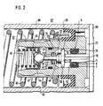
- FIG. 2 An embodiment of the invention with a protective device is subsequently based on FIG. 2 explained. It is based on the central valve the description of Fig. 1 and in terms of design the protection valve referred to DE-OS 40 32 873.
- the master brake cylinder 67 consists of a Housing 68 with a blind bore 63 in which a piston 1 is sealed.
- a spring 60 is between one, not shown Secondary piston and the piston 1 arranged
- a central valve 6, 38 is arranged in the piston 1. A more detailed description of the central valves takes place below.
- a plunger 19 extends in the axis of the piston 1 and, as will be explained below, serves as Actuation for the central valve 6.38.
- the plunger 19 is located on a cross pin 59 only partially shown and keeps the central valve 6.38 open.
- the piston 1 delimits a working chamber 62 which with the brake circuits and with the output of the pump connected is.
- the plunger 19 is in a narrow longitudinal bore led, the same time the pressure medium exchange between the working chamber 62 on the one hand and one Storage container on the other hand serves. So that one undisturbed pressure medium compensation can take place
- Compensating bore 23 is provided in the piston 1 be, which is essentially transverse to the longitudinal axis of the Alternatively, the plunger 19 can also extend the piston be provided with longitudinal grooves.
- the piston 1 has a multi-step longitudinal bore 31 provided, which is from the front side, the Working space 62 limited to the compensating bore 23 extends.
- the largest step of the longitudinal bore can be found in direct connection to the front side of the work area 62.
- This section ends at level 32 a cylindrical insert 33 is supported.
- the insert 33 is provided with a seal 34, which seals the insert on the outer jacket, with what only a pressure medium flow through the central channel of insert 33 is allowed.
- the insert 33 can also seal due to a special outer contour be pressed into the hole.
- the central one The channel is at its working space 62 Provide end with a hardened valve seat 35. from Insert 33 extends from another Piece of the longitudinal bore 31 to a second stage 36, which has an annular surface.
- a final channel 5 in which the actuating plunger 19 is guided. From channel 5 branches off the compensating bore 23. this makes possible it, the channel 5 very narrow at least in some areas execute so that it acts as a guide for the plunger 19th can serve.
- a closing body 38 is arranged, to which the plunger 19 is molded.
- the diameter of the closing body 38 corresponds essentially to that Diameter of this section of the longitudinal bore 31, so that guidance is given.
- a pressure medium flow on Closing body 38 is passed through openings 39 on Realized the outer edge of the closing body 38.
- the central valve has a movable seat Closing body 38 made of steel, between an actuating pin 43 and the plunger 19 is inserted.
- This movable closing body 38 acts with a valve insert 6 together, in the second stage 36 of the longitudinal bore 31 is used
- the stationary one Valve insert 6 essentially from an annular Valve seat 7, which is applied to a support insert 8. Further details on this are explained in relation to FIG. 1.
- the Support insert 8 also forms a stop for the movable closing body 38.
- a ring shaped in Bead extending towards the closing body 38 53 provides the necessary sealing for the central valve 6.38 in its closed state.
- the distance between the bead 53 and the closing surface of the Closing body 38 is designated B.
- the actuating pin 43 protrudes through the central one Channel of the insert 33 and lies on one Valve ball 44 on, which cooperates with the valve seat 35.
- the valve ball 44 is held by one Guide element 45 on which a spring 46 is supported is.
- This spring 46 is supported on its other side from a sleeve 47, which is placed on the piston 1. It should also be noted that between the insert 33 and the closing body 38, a spring 49 is supported which, like the spring 46, ensures that the each valve closes securely.
- connection of the valve body 38 to the actuating pin 43 is tuned so that in the basic position the first valve, formed from the central valve Valve ball 44 and valve seat 35 a first opening distance A while the second valve, formed from the valve seat 7 or the bead 53 and the Closing body 38, a second opening distance B having.
- the first opening distance A is smaller than that second opening distance B.
- the piston 1 of the master cylinder works like follows: The figure shows an unactuated state of the Master brake cylinder i.e. the central valve is located in an open state. The piston 1 is located in its basic position, the plunger 19 lies on the associated one Cross pin 59 so that the formed on the piston 1 Valve seat 35 is at a distance from valve ball 44 located. There is a pressure medium connection between the working chamber 62 and the reservoir. If the brake pedal is now operated, it shifts the push rod piston 1 under the influence of the pedal force to the left in the drawing and takes over the spring 60 with a secondary piston, not shown.
- valve seat 38 approaches the bead 53.
- the central valve 6,38 also closes. This happens depressurized, because in the space between the two Individual valves no pressure is built up. So it happens no damage to the rubber or any other suitable sealing material existing valve seat 7th
Landscapes
- Engineering & Computer Science (AREA)
- Transportation (AREA)
- Mechanical Engineering (AREA)
- Transmission Of Braking Force In Braking Systems (AREA)
- Valves And Accessory Devices For Braking Systems (AREA)
- Braking Arrangements (AREA)
Description
Die Erfindung betrifft einen Kolben der sich aus dem Oberbegriff des Hauptanspruchs ergebenden Gattung. Derartige Kolben sind aus der DE-OS 39 32 248 bekannt.The invention relates to a piston resulting from the General term of the genus resulting in the main claim. Such pistons are from DE-OS 39 32 248 known.
Als nachteilig bei dem verwendeten Zentralventil wird empfunden, daß bei dem Einbau des Ventileinsatzes, also der Kombination aus Ventilsitz und Stützeinsatz, besondere Sorgfalt verwendetwerden muß. Ist der Ventilstift mit dem Stützeinsatz, beispielsweise durch Vulkanisieren oder Verkleben, nicht besonders zuverlässig verbunden, so kann es geschehen, daß beim Einfügen des gesamten Ventileinsatzes sich der Ventilsitz durch die seitliche Reibung an der Aufnahmebohrung im Kolben vom Stützeinsatz löst. Das kommt daher, daß gegenüber einer axialen Verschiebung der beiden Einsätze nur die Kräfte entgegenwirken können, die durch Reibschluß bzw. die Haftwirkung des Klebers gegeben sind.As a disadvantage with the central valve used it is felt that when installing the valve insert, i.e. the combination of valve seat and support insert, special care must be taken. Is the Valve pin with the support insert, for example by Vulcanizing or gluing, not particularly reliable connected, it can happen that when inserting of the entire valve insert is the valve seat due to the lateral friction on the mounting hole in the The piston releases from the support insert. This is because against an axial displacement of the two inserts can only counteract the forces caused by Friction or the adhesive effect of the adhesive are.
Die WO-A-9206875 zeigt ein aus zwei Einzelventilen bestehendes Zentralventil eines Hauptbremszylinders einer blockiergeschützten hydraulischen Bremsanlage. Diese Einzelventile sind in einer gestuften Bohrung eines Kolbens des Hauptbremszylinders hintereinander angeordnet.WO-A-9206875 shows one of two individual valves existing central valve of a master brake cylinder an anti-lock hydraulic Brake system. These single valves are in a tiered Bore a piston of the master brake cylinder arranged one behind the other.
Eines der Ventile weist einen metallischen Ventilsitz und einen elastischen Dichtkörper auf, während bei dem anderen Ventil, welches zeitlich vor dem ersten Ventil schließt bzw. nach diesem öffnet, eine Metall-auf-Metall-Dichtung realisiert ist. Dies gewährleistet einen Schutz des elastischen Dichtkörpers vor Zerstörung, die während einer Blockierschutzregelung auftreten könnte. Um die beiden Einzelventile in der Bohrung hintereinander anordnen zu können, ist der Dichtsitz des zweiten Ventils als metallisches, in der Bohrung angeordnetes Einsatzstück ausgebildet. Der elastische Dichtkörper ist am Ventilkörper des ersten Ventils befestigt. Die Herstellung eines derartigen Ventils ist daher relativ aufwendig.One of the valves has a metallic valve seat and an elastic sealing body, while in the other valve, which is before the first valve closes or opens after this, a metal-on-metal seal is realized. This ensures protection of the elastic sealing body from destruction, the could occur during anti-lock control. Around the two individual valves in the bore in a row to be able to arrange is the tight fit of the second Valve as a metallic, arranged in the bore Insert piece trained. The elastic sealing body is attached to the valve body of the first valve. The production such a valve is therefore relatively expensive.
Aus der DE-C1-38 10 447 ist ein elastisches Dichtelement bekannt, welches an die Außenfläche eines rohrförmigen, einseitig mit einem Flansch versehenen Teils angeformt ist. Dabei steht das elastische Dichtelement auf der dem Flansch abgewandten Seite des rohrförmigen Teils etwas über dieses hinaus. Nähert sich ein Ventilelement dem elastischen Dichtelement, so wird dieses zunächst elastisch verformt, bis das Ventilelement am rohrförmigen Teile zur Anlage kommt. Auch hier ist der verhältnismäßig große Produktionsaufwand, insbesondere zur Befestigung mittels eines Sicherungselements, festzustellen.DE-C1-38 10 447 is an elastic sealing element known, which on the outer surface of a tubular, flanged on one side Is partially molded. The elastic sealing element is there on the side facing away from the flange of the tubular Some something beyond this. Approaches Valve element the elastic sealing element, so this first deformed elastically until the valve element comes into contact with the tubular parts. Here too is the relatively large production effort, in particular for attachment by means of a securing element, determine.
Die Erfindung geht daher aus von einem Kolben der eingangs genannten Gattung und hat sich zur Aufgabe gestellt, diesen Kolben weiter zu vereinfachen, indem er insbesondere leichter hergestellt und montiert werden kann.The invention is therefore based on a piston genus mentioned at the beginning and has the task asked to further simplify this piston by especially easier to manufacture and assemble can.
Diese Aufgabe wird durch die sich aus dem kennzeichnenden Teil des Hauptanspruchs ergebenden Merkmale gelöst. Die Erfindung besteht im Prinzip also darin, die Kombination aus Ventilsitz und Stützeinsatz mit in axialer Richtung hinreichenden Hinterschneidungen zu versehen, die die bei der Montage, aber auch während des Betriebs auftretenden axialen Kräfte ohne Schwierigkeiten aufzunehmen vermögen, so daß sich der Ventilsitz gegenüber dem Stützeinsatz nicht in axialer Richtung verschieben kann.This task is characterized by the distinctive Part of the main claim Features solved. In principle, the invention therefore exists in it, the combination of valve seat and support insert with sufficient undercuts in the axial direction to be provided, which during assembly, but also axial forces occurring during operation without Able to absorb difficulties, so that the valve seat is not in axial relation to the support insert Can shift direction.
Ferner ist der Durchmesser einer Axialbohrung des Ventileinsatzes größer als der Durchmesser einer sich anschließenden axialen Bohrung des Zentralventil Kanals im Kolben.Furthermore, the diameter of an axial bore of the valve insert larger than the diameter of a subsequent axial bore of the central valve channel in the piston.
Bei dem vorbekannten Ventileinsatz gemäß der DE-OS 39 32 248 ragt der Stützeinsatz mit einem ringförmigen Ende in eine gestufte Bohrung des Kolbens. Um den Ventileinsatz daher montieren zu können, sind spiralförmige Entlüftungsnuten notwendig und hinsichtlich des Ventileinsatzes ergibt sich eine in der Regel unerwünschte doppelte Zentrierung. Die hierfür notwendigen genauen Fertigungstoleranzen lassen sich nur schwer herstellen. Andererseits soll dieser Ventileinsatz gleichzeitig zur maßhaltigen Führung des Ventilstößels verwendet werden. Wendet man dieses Prinzip auf den vorliegenden Ventilsitz an, so müßte der Stößel durch zwei miteinander fluchtende Bohrungen geführt werden. Hierdurch könnten sich Schwierigkeiten ergeben, die durch die Merkmalskombination gemäß Anspruch 1 beseitigt werden. Der Ventilstößel wird somit nur in der Axialbohrung des Kolbens geführt, so daß die Wände des axialen Kanals gleichzeitig als Führungsflächen dienen.In the previously known valve insert according to DE-OS 39 32 248 the support insert protrudes with an annular End in a stepped bore of the piston. To the The ability to mount the valve insert is therefore spiral Ventilation grooves necessary and with regard to Valve insert is usually an undesirable result double centering. The necessary for this exact manufacturing tolerances are difficult produce. On the other hand, should this valve insert at the same time to true to size Guide of the valve lifter can be used. applies you apply this principle to the existing valve seat, so the plunger would have to be aligned by two Holes are performed. This could result in Difficulties arise by the combination of features according to claim 1 can be eliminated. The valve lifter is therefore only guided in the axial bore of the piston, so that the Walls of the axial channel simultaneously as guide surfaces serve.
Um weitere Vereinfachungen zu schaffen, empfiehlt sich die
Anwendung der in Anspruch 2 aufgeführten Merkmalskombination.
Mit anderen Worten bedeutet dies, daß
auf den ringförmigen Ansatz am Stützeinsatz und damit
auf eine durchgehende Führung des Ventilstößels innerhalb
dieses Stützeinsatzes verzichtet wird, wodurch der
Ventileinsatz in beiden axialen Lagen verbaubar wird.
Hinzukommt, daß die Dichtwirkung des Ventileinsatzes
gegenüber der Kolbenbohrung noch erhöht wird, da
durch die beidseitige Dichtfläche auch die Stirnfläche
des Ventileinsatzes zur Abdichtung gegenüber der Kolbenbohrung
am Boden dieser Bohrung beiträgt. Der
Ventileinsatz wird durch die genannte Maßnahme auch
einfacher hergestellt, da die Lage des Stützeinsatzes
während der Verbindung mit dem Ventilsitz gleichgültig
ist.To create further simplifications, the
Application of the combination of features listed in
Bei dem bekannten Zentralventil gemäß DE-OS 39
32 248 ist der Ventilkörper mit einem ringförmigen Vorsprung
versehen, um die Dichtwirkung zu erhöhen.
Nachteile können dabei sein, daß durch die starren
Kanten des Ventilkörpers der Dichtsitz des Ventilsitzes
unter Umständen verletzt werden kann. Als nachteilig
wird weiterhin angesehen, daß der ringförmige Vorsprung
sehr genau gefertigt werden muß, so daß hier in
der Regel eine Nachbearbeitung notwendig sein wird.
Zwar ließe sich hier durch besonders maßgenaue
Gießverfahren, wie beispielsweise Aluminium-Druckguß,
Abhilfe schaffen, für derartige Verfahren sind aber
die Herstellungskosten hoch. Als Abhilfe hierzu wird in
Verbesserung der Erfindung die Merkmalskombination
nach Anspruch 3 vorgeschlagen. Die erhöhte Dichtwirkung
wird also hier durch Angießen eines ringförmigen
Vorsprungs an den Ventilsitz erreicht. Durch diese
Maßnahme ist es möglich, den Ventilkörper in einfacher
Weise als geschlagenes Stahiteil auszuführen und auf
ein Gußverfahren zu verzichten.In the known central valve according to DE-OS 39
32 248 is the valve body with an annular projection
provided to increase the sealing effect.
Disadvantages can be that the rigid
Edges of the valve body the sealing seat of the valve seat
can possibly be injured. As a disadvantage
it is further considered that the annular projection
must be manufactured very precisely, so that here in
usually post-processing will be necessary.
It is true that this could be achieved through particularly precise measurements
Casting processes, such as aluminum die casting,
To remedy the situation, but for such procedures
the manufacturing cost high. As a remedy for this, in
Improvement of the invention the combination of features
proposed according to
Wird hierbei der Ventileinsatz symmetrisch ausgeführt, so empfiehlt sich in Verbesserung der Erfindung die Verwendung der Merkmale nach Anspruch 4. Da bei symmetrischem Aufbau des Ventileinsatzes jede der beiden Stirnflächen des Ventilsitzes mit einem ringförmigen Vorsprung versehen ist, stellt die ringförmige Aufnahmeausnehmung eine Möglichkeit dar, die Maßhaltigkeit des Ventileinsatzes gegenüber dem Kolben zu verbessern. Außerdem werden mögliche Axialkräfte, die von dem am Boden der Bohrung eingepreßten ringförmigen Vorsprung ausgehen könnten, von dem Ventileinsatz femgehalten.If the valve insert is designed symmetrically, so is recommended in improving the invention the use of the features of claim 4. Since at symmetrical structure of the valve insert each of the two End faces of the valve seat with an annular Is provided, provides the annular receiving recess one way is dimensional accuracy to improve the valve insert compared to the piston. In addition, possible axial forces of the ring-shaped pressed in at the bottom of the bore Could lead from the valve insert femgehalten.
Beim Angießen des Ventilsitzes an den Stützeinsatz muß dieser zuvor in eine Form eingespannt werden. Um hierbei die axiale Bohrung des Stützeinsatzes nicht zu verletzen, wird die Anwendung der Merkmale nach Anspruch 5 empfohlen.When pouring the valve seat onto the support insert this must first be clamped in a form. Around the axial bore of the support insert is not closed violate, the application of the features according to claim 5 recommended.
Um die erfindungsgemäße Hinterschneidung
zwischen Ventilsitz und Stützeinsatz zu erreichen, sind
eine ganze Reihe von Ausformungen des Stützeinsatzes
möglich. Eine besonders einfache und zuverlässig wirkende
Ausformung beschreibt die Merkmalskombination
nach Anspruch 6. Ein derart ausgeformter Stützeinsatz
läßt sich besonders einfach durch ein Gußvedahren
oder Preßverfahren gewinnen.To the undercut according to the invention
can be reached between the valve seat and the support insert
a whole range of shapes of the support insert
possible. A particularly simple and reliable looking
Forming describes the combination of features
according to
Anspruch 7 beschreibt eine weitere Möglichkeit zur Ausgestaltung des Stützeinsatzes, durch den sich eine erhöhte Festigkeit, insbesondere in axialer Richtung erreichen läßt.Claim 7 describes a further possibility Design of the support insert through which a increased strength, especially in the axial direction can be achieved.
Als Materialkombination hat sich die Verwendung von Aluminium sowohl für den Stützeinsatz, als auch den Kolben selbst bewährt. Dabei ist der Aufbau der Einzelteile zueinander so gewählt, daß durch den aus einem anderen Material, nämlich vorzugsweise Stahl, gefertigten Ventilkörper keine nachteiligen Folgen entstehen. Hilfsweise kann es sich empfehlen, die aufeinander gleitenden Flächen unterschiedlichen Metalls durch Beschichtung voneinander zu isolieren, was beispielsweise durch Vernickein, durch Verzinken o.ä. geschehen kann.The use has become a material combination of aluminum for both the support insert and the Piston proven itself. The structure of the Items chosen to each other so that from the another material, namely preferably steel, manufactured valve body no adverse consequences arise. Alternatively, it can be recommended that sliding surfaces of different metal isolate from each other by coating what for example by nickel-plating, by galvanizing or the like. can happen.
Erfindungsgemäße Kolben werden in Hauptbremszylindern mit Zentralventil für blockiergeschützte, hydraulische Bremsanlagen (ABS) benötigt. Bei diesen Bremsanlagen besteht die Schwierigkeit, daß das Zentralventil auch unter Druck geöffnet werden muß. Hierdurch besteht die Gefahr, daß der aus relativ weichem elastischen Material bestehende Ventilsitz durch die auftretenden Strömungskräfte an dem sich öffnenden Ventil beschädigt wird. Die in diesem Zusammenhang bestehende Problematik ist ausführlich in der DE-OS 40 40 271 beschrieben worden. Weiterhin ist in der DE-OS 40 32 873 eine Lösung angegeben worden, bei der zwei Ventile in Reihe geschaltet wurden. Ein anderer in diesem Zusammenhang gemachter Vorschlag (DE-A-42 23 353, veröffentlicht am 20.01.94) geht dahin, die Funktion des das Zentralventil schützenden zweiten Ventils durch eine einfache oder über Differenzdruck steuerbare Blende zu ersetzen.Pistons according to the invention are in master brake cylinders with central valve for anti-lock, hydraulic braking systems (ABS) required. With these Braking systems face the difficulty that the central valve must also be opened under pressure. hereby there is a risk that the relatively soft elastic material existing valve seat through the occurring flow forces at the opening Valve is damaged. The related existing problems are detailed in DE-OS 40 40 271. Furthermore, in the DE-OS 40 32 873 a solution was given in which two Valves were connected in series. Another in related proposal (DE-A-42 23 353, published on 01/20/94) goes there, the function of the second valve protecting the central valve by a simple or controllable via differential pressure Panel to replace.
Eine weitere Aufgabe der Erfindung besteht darin, den Aufbau des Zentralventils einschließlich der zugehörigen weiter oben erläuterten Schutzeinrichtungen sowohl hinsichtlich der Zuverlässigkeit und Geschwindigkeit der Arbeitsweise des Zentralventils zu verbessern als auch das Zentralventil beim Öffnen gegen hohen Druck in der Arbeitskammer besser zu schützen. Dabei kann das gattungsgemäße Zentralventil mit einzelnen der weiter oben beschriebenen Merkmale oder deren Kombination versehen sein.Another object of the invention is the structure of the central valve including the associated one protective devices explained above both in terms of reliability and speed improve the operation of the central valve as well as the central valve when opening against high To better protect pressure in the working chamber. there can the generic central valve with individual the features described above or their Combination.
Diese Aufgabe wird durch die sich aus dem kennzeichnenden
Teil des Anspruchs 9 ergebende Merkmalskombination
gelöst. Die Erfindung besteht im
Prinzip also darin, für das gattungsgemäße Zentralventil
eine steuernde Schutzeinrichtung vorzusehen, welche
die über das Zentralventil, insbesondere beim Druck im
Arbeitszylinder, maximal fließende Druckmittelmenge
begrenzt.This task is characterized by the distinctive
Combination of features resulting in part of
Dabei kann nach vorteilhaften Weiterbildungen der Erfindung die steuernde Schutzeinrichtung als feststehende Blende, aber auch als dynamische Blende ausgeführt sein. Einzelheiten hierzu sind näher in der P 42 23 353 erläutert.According to advantageous developments of the Invention the controlling protective device as a fixed Aperture, but also designed as a dynamic aperture his. Details on this can be found in P 42 23 353 explained.
Eine andere vorteilhafte Weiterbildung der Erfindung
kann in der Anwendung eines vorgeschalteten
Schutzventils bestehen, wie es im Prinzip beispielsweise
in der DE-OS 40 32 873 erörtert ist. Zusätzliche vorteilhafte
Weiterbildungen sind hierzu in den Unteransprüchen
13 bis 22 aufgeführtAnother advantageous development of the invention
can in the application of an upstream
Protection valve exist, as in principle for example
is discussed in DE-OS 40 32 873. Additional beneficial
Further training is in the
Zwei Ausführungsbeispiele der Erfindung werden nachfolgend anhand der Abbildungen beschrieben.Two embodiments of the invention will be described below using the illustrations.
Dabei zeigen:
- Fig. 1
- einen erfindungsgemäßen Kolben mit Zentralventil
- Fig. 2
- einen erfindungsgemäßen Kolben mit zusätzlichem Schutzventil
- Fig. 1
- a piston according to the invention with a central valve
- Fig. 2
- a piston according to the invention with an additional protective valve
Der in abgeschnittener Darstellung gezeigte Kolben
1, der beispielsweise der Druckstangenkolben oder der
Sekundärkolben eines Tandem-Hauptzylinders sein
kann, ist mit einer Stufenbohrung 2 versehen, die sich
aus einem ersten Bohrungsabschnitt großen
Durchmessers (Hohlraum 3) und einem hierzu gestuften
zweiten Bohrungsabschnitt 4 mit geringfügig vermindertem
Durchmesser und einem dritten Bohrungsabschnitt
(zentraler Kanal 5) stark verminderten Durchmessers
zusammensetzt.The piston shown in a cutaway view
1, for example the push rod piston or the
Secondary piston of a tandem master cylinder
can, is provided with a stepped
Die Zeichnung zeigt einen Ventileinsatz 6, zu dem
ein Ventilsitz 7 sowie ein Stützeinsatz 8 gehört. Der Ventilsitz
7 ist auf den Stützeinsatz 8 vulkanisiert bzw.
gegossen. Um die Aufnahme axialer Kräfte zwischen
Ventilsitz und Stützeinsatz 8 zu verbessern, ist der
Stützeinsatz 8 mit einem ringförmigen Bund 9A, 9B
versehen. Die Zeichnung zeigt hinsichtlich des Bundes
zwei Versionen, die wahlweise verwendet werden können.
Auf der rechten Seite der Zeichnung ist ein Bund
9A mit rechteckförmigem Querschnitt gezeigt, der vorzugsweise
angewendet wird. Eine andere Möglichkeit
besteht darin, den Bund 9B, wie auf der linken Seite der
Zeichnung gezeigt, mit einer im wesentlichen konischen
Form zu versehen, die in einen rechteckförmigen
Abschnitt übergeht.The drawing shows a
Der Ventileinsatz 6 ist zu seiner quer zur Längsachse
der Bohrung 3 liegenden Mittelebene hin symmetrisch
aufgebaut, so daß er in beiden Lagen verbaut
werden kann. Die Axialbohrung 10 des Stützeinsatzes 8
hat einen größeren Durchmesser als der zentrale Kanal
5. An den beiden Enden der Axialbohrung 10 ist diese
mit zwei ringförmigen Ausnehmungen 11 und 12 versehen,
die bei der Herstellung des Ventileinsatzes 6 verhindern
sollen, daß die Bohrung 10 sich an ihren Enden
beim Fertigungsprozeß verjüngt.The
Der Ventilsitz 7 trägt zumindest an einer seiner beiden
Stirnflächen 15,16 einen ringförmigen Vorsprung
13, der zur verbesserten Abdichtung gegenüber einem
Ventilkörper 17 dient. Auf der rechten Seite der Zeichnung
ist eine symmetrische Ausgestaltung hinsichtlich
des ringförmigen Vorsprungs dargestellt, so daß der
Ventilsitz 7 in diesem Falle die ringförmigen Vorsprünge
13 und 14 besitzt. Dabei ist es vorteilhaft, wenn der Kolben
1 am Boden des zweiten Bohrungsabschnittes 4 mit
einer entsprechenden ringförmigen Aufnahme 18 versehen
ist, um für die Stirnfläche 16 eine glatte Anlagefläche
am Boden des Bohrungsabschnittes zu schaffen. Es ist
aber auch möglich, entsprechend der linken Seite der
Zeichnung auf die ringförmige Aufnahme 18 zu verzichten.
In diesem Falle ist es auch vorteilhaft, wenn der Ventilsitz
nur einseitig einen ringförmigen Vorsprung 13
besitzt. Eine vollkommene Symmetrie des Ventileinsatzes
6 ist in diesem Falle nicht mehr gegeben.The valve seat 7 carries at least one of its two
End faces 15,16 an
Der Ventilkörper 17 ist mit einem Stößel 19 versehen.
Dabei ist der Durchmesser der Axialbohrung 10 so
viel größer als der Durchmesser des zentralen Kanals 5
gewählt, daß der Stößel 19 an der Mantelfläche des zentralen
Kanals 5 geführt ist. Da der Kanal 5 gleichzeitig
auch als Druckmittelkanal dient, stützt sich der Stößel
19 nur mit Hilfe von vorzugsweise drei Stegen 20 an den
Bohrungswänden ab. Die Stege 20 verlaufen in Längsrichtung
der Achse der Stufenbohrung 2 und sind
gleichmaßig auf dem Umfang des Stößels verteilt.The
Der Ventilkörper 17 ist mittels einer Spiralfeder 21
gegenüber dem Ventilsitz 7 vorgespannt, wobei die
Feder 21 sich an dem Kolben mittels eines Stützrings 22
abstützt, der mit dem Kolben 1 verstemmt oder in einer
anderen Weise dauerhaft fixiert ist. Der Stützring 22
kann aber auch in eine entsprechende Nut eingerastet
sein, um den Ausbau des Zentralventils zu vereinfachen.The
Hinsichtlich der Materialien besteht der Kolben 1
und Stützeinsatz 8 aus Aluminium, während der Ventilkörper
17 aus Stahl gepreßt, beispielsweisegeschmiedet
oder geschlagen ist.With regard to the materials, there is piston 1
and
Ein Ausführungsbeispiel der Erfindung mit Schutzeinrichtung wird nachfolgend anhand der Fig. 2 erläutert. Dabei wird hinsichtlich des Zentralventils auf die Beschreibung zu Fig. 1 und hinsichtlich der Ausgestaltung des Schutzventils auf die DE-OS 40 32 873 verwiesen.An embodiment of the invention with a protective device is subsequently based on FIG. 2 explained. It is based on the central valve the description of Fig. 1 and in terms of design the protection valve referred to DE-OS 40 32 873.
Der Hauptbremszylinder 67 besteht aus einem
Gehäuse 68 mit einer Sackbohrung 63, in der ein Kolben
1 dichtend geführt ist.The
Eine Feder 60 ist zwischen einem nicht dargestellten
Sekundärkolben und dem Kolben 1 angeordnetA
In dem Kolben 1 ist ein Zentralventil 6,38 angeordnet.
Eine genauere Beschreibung der Zentralventile
erfolgt weiter unten.A
Ein Stößel 19 erstreckt sich in der Achse des Kolbens
1 und dient, wie weiter unten erläutert wird, als
Betätigung für das Zentralventil 6,38. Der Stößel 19 liegt
an einem nur teilweise dargestellten Querstift 59 an und
hält das Zentralventil 6,38 offen.A
Der Kolben 1 begrenzt eine Arbeitskammer 62, die mit den Bremskreisen und mit dem Ausgang der Pumpe verbunden ist.The piston 1 delimits a working chamber 62 which with the brake circuits and with the output of the pump connected is.
Der Stößel 19 ist in einer engen Längsbohrung
geführt, die gleichzeitig dem Druckmittelaustausch
zwischen der Arbeitskammer 62 einerseits und einem
Vorratsbehälter andererseits dient. Damit ein
ungestörter Druckmittelausgleich stattfindet, kann eine
Ausgleichsbohrung 23 in dem Kolben 1 vorgesehen
sein, die sich im wesentlichen quer zur Längsachse des
Kolbens erstreckt Ersatzweise kann auch der Stößel 19
mit Längsnuten versehen werden.The
Der Kolben 1 ist mit einer mehrfach gestuften Längsbohrung
31 versehen, die sich von der Stirnseite, die den
Arbeitsraum 62 begrenzt, bis zur Ausgleichsbohrung 23
erstreckt. Die größte Stufe der Längsbohrung findet sich
im unmittelbaren Anschluß an die Stirnseite zum Arbeitsraum
62. Dieser Abschnitt endet an einer Stufe 32, an
der ein zylinderförmiges Einsatzstück 33 abgestützt ist.
Das Einsatzstück 33 ist mit einer Dichtung 34 versehen,
die das Einsatzstück am Außenmantel abdichtet, womit
lediglich ein Druckmittelfluß durch den zentralen Kanal
des Einsatzstücks 33 erlaubt ist. Das Einsatzstück 33
kann auch auf Grund einer speziellen Außenkontur dichtend
in die Bohrung eingedrückt werden. Der zentrale
Kanal ist an seinen dem Arbeitsraum 62 zugewandten
Ende mit einem gehärteten Ventilsitz 35 versehen. Vom
Einsatzstück 33 ausgehend erstreckt sich ein weiteres
Stück der Längsbohrung 31 bis zu einer zweiten Stufe
36, die eine ringförmige Fläche aufweist. An die zweite
Stufe 36 schließt sich ein abschließender Kanal 5 an, in
dem der Betätigungsstößel 19 geführt ist. Vom Kanal 5
zweigt auch die Ausgleichsbohrung 23 ab. Dies ermöglicht
es, den Kanal 5 zumindest in Teilbereichen sehr eng
auszuführen, so daß er als Führung für den Stößel 19
dienen kann.The piston 1 has a multi-step
Im Raum zwischen der ersten Stufe 32 und der
zweiten Stufe 36 ist ein Schließkörper 38 angeordnet,
an den der Stößel 19 angeformt ist. Der Durchmesser
des SchlieBkörpers 38 entspricht im wesentlichen dem
Durchmesser dieses Teilstückes der Längsbohrung 31,
so daß eine Führung gegeben ist. Ein Druckmittelfluß am
Schließkörper 38 vorbei wird durch Durchlässe 39 am
Außenrand des Schließkörpers 38 realisiert.In the space between the
Das Zentralventil besitzt als beweglichen Sitz den
Schließkörper 38 aus Stahl, der zwischen einen Betätigungsstift
43 und den Stößel 19 eingefügt ist. Dieser
bewegliche Schließkörper 38 wirkt mit einem Ventileinsatz
6 zusammen, der in die zweite Stufe 36 der Längsbohrung
31 eingesetzt ist Dabei besteht der ortsfeste
Ventileinsatz 6 im wesentlichen aus einem ringförmigen
Ventilsitz 7, der auf einem Stützeinsatz 8 aufgebracht ist.
Nähere Einzelheiten hierzu sind zu Fig. 1 erläutert. Der
Stützeinsatz 8 bildet gleichzeitig einen Anschlag für den
beweglichen Schließkörper 38. Eine ringförmig sich in
Richtung zu dem Schließkörper 38 erstreckende Wulst
53 sorgt für die notwendige Dichtung des Zentraiventils
6,38 in dessen geschlossenem Zustand. Der Abstand
zwischen dem Wulst 53 und der Schließfläche des
Schließkörpers 38 wird mit B bezeichnet.The central valve has a movable
Der Betätigungsstift 43 ragt durch den zentralen
Kanal des Einsatzstückes 33 hindurch und liegt an einer
Ventilkugel 44 an, die mit dem Ventilsitz 35 zusammenwirkt.
Die Ventilkugel 44 wird gehalten von einem
Führungselement 45, an dem eine Feder 46 abgestützt
ist. Diese Feder 46 stützt sich auf ihrer anderen Seite an
einer Hülse 47 ab, die auf den Kolben 1 aufgesetzt ist.
Anzumerken ist auch, daß zwischen dem Einsatzstück
33 und dem Schließkörper 38 eine Feder 49 abgestützt
ist, die ebenso wie die Feder 46 dafür sorgt, daß das
jeweilige Ventil sicher schließt.The
Die Verbindung des Ventilkörpers 38 mit dem Betätigungsstift
43 ist so abgestimmt, daß in der Grundstellung
des Zentralventils das erste Ventil, gebildet aus
Ventilkugel 44 und Ventilsitz 35 einen ersten Öffnungsabstand
A aufweist, während das zweite Ventil,
gebildet aus dem Ventilsitz 7 bzw. dem Wulst 53 und dem
Schließkörper 38, einen zweiten Öffnungsabstand B
aufweist. Der erste Öffnungsabstand A ist kleiner als der
zweite Öffnungsabstand B.The connection of the
Der Kolben 1 des Hauptbremszylinders arbeitet wie
folgt: Die Figur zeigt einen unbetätigten Zustand des
Hauptbremszylinder d.h. das Zentralventil befindet sich
in einem geöffneten Zustand. Der Kolben 1 befindet sich
in seiner Grundposition, der Stößel 19 liegt am zugehörigen
Querstift 59 an, so daß der am Kolben 1 ausgebildete
Ventilsitz 35 sich im Abstand zur Ventilkugel 44
befindet. Es besteht eine Druckmittelverbindung
zwischen der Arbeitskammer 62 und dem Vorratsbehälter.
Wird nun das Bremspedal betätigt, so verschiebt sich
der Druckstangenkolben 1 unter Einfluß der Pedalkraft
in der Zeichnung nach links und nimmt über die Feder
60 einen nicht gezeigten Sekundärkolben mit. Die Kolben
werden also relativ zum Gehäuse 68 verschoben,
während der Stößel 11, der Schließkörper 38, der Betätigungsstift
43 und die Ventilkugel 44 relativ zum
Gehäuse des Hauptbremszylinders nicht verschoben
werden. Die Federn halten die Ventilkörper in ihrer Position.
Sobald der Kolben 1 den ersten Öffnungsabstand
A zurückgelegt hat, legt sich der Ventilsitz 35 an die Ventilkugel
44 an, so daß die obengenannte Verbindung
Zwischen der Arbeitskammer 62 auf der einen Seite und
dem Vorratsbehälter auf der anderen Seite unterbrochen
wird. In der Arbeitskammer 62 kann nun bei weiterer Verschiebung
des Kolbens ein Druck aufgebaut werden.The piston 1 of the master cylinder works like
follows: The figure shows an unactuated state of the
Master brake cylinder i.e. the central valve is located
in an open state. The piston 1 is located
in its basic position, the
Wird der Kolben 1 weiter nach links bewegt, so löst
sich der Betätigungsstift 43 von der Ventilkugel 44, und
der Ventilsitz 38 nähert sich dem Wulst 53. Sobald der
Kolben 1 den zweiten Öffnungsabstand B zurückgelegt
hat, schließt auch das Zentralventil 6,38. Dies geschieht
drucklos, da in dem Zwischenraum zwischen den beiden
Einzelventilen kein Druck aufgebaut ist. Es erfolgt somit
keine Beschädigung des aus Gummi oder einem
anderen geeigneten Dichtmaterial bestehenden Ventilsitzes
7.If piston 1 is moved further to the left, it releases
the
Solange das erste Schutzventil 44,35 sicher schließt, ist das Verhalten des Zentralventils 6,38 ohne Bedeutung.As long as the first protection valve 44.35 is safe closes, the behavior of the central valve is 6.38 without Importance.
In einem Regelvorgang, wenn von der Pumpe
Druckmittel in die Arbeitskammer 62 gefördert wird, wird
der Kolben 1 zurück auf seine Grundposition geschoben.
Dann öffnet zunächst wieder das Zentralventil 6,38 und
als nächstes das Schutzventil 44,35. Nun kann Druckmittel
über das sich öffnende Schutzventil 44,35 und an
dem offenen Zentralventil 6,38 - der Öffnungsspalt
beträgt B minus A - vorbeifließen. Wegen des zunächst
noch geschlossenen Schutzventils 44,35 ist die über das
Zentralventil 6,38 abfließende Druckmittelmenge
begrenzt, so daß eine Zerstörung der Gummidichtung
(Ventilsitz 7) vermieden wird. Der sich einstellende
kleine Druckabbau in der Arbeitskammer 62 führt dazu,
daß der Arbeitskolben 1 wiederum nach links geschoben
wird und das Schutzventil 44,35 schließt. Infolgedessen
läuft ein Regelvorgang ab, der aus schnell aufeinanderfolgenden
Öffnungs- und Schließvorgängen des Schutzventils
44,35 besteht. Dann kann letztlich soviel Druckmittel
über das Ventil abfließen, wie von der Pumpe in
den Hauptzylinder gefördert wird. Der Hauptzylinderdruck
entspricht dabei dem Pedaldruck.In one control process, if from the pump
Pressure medium is pumped into the working chamber 62
the piston 1 is pushed back to its basic position.
Then the
- 11
- Kolbenpiston
- 22
- Stufenbohrungstepped bore
- 33
- Hohlraumcavity
- 44
- Bohrungsabschnittbore section
- 55
- zentraler Kanal central channel
- 66
- Ventileinsatzvalve core
- 77
- Ventilsitzvalve seat
- 88th
- Stützeinsatzsupport insert
- 9A9A
- ringförmiger Bundring-shaped waistband
- 9B9B
- ringförmiger Bundring-shaped waistband
- 1010
- axiale Bohrungaxial bore
- 1111
- ringförmige Ausnehmungannular recess
- 1212
- ringförmige Ausnehmungannular recess
- 1313
- ringförmiger Vorsprungannular projection
- 1414
- ringförmiger Vorsprungannular projection
- 1515
- Stirnflächeface
- 1616
- Stirnflächeface
- 1717
- VenfilkörperVenfilkörper
- 1818
- ringförmige Aufnahmering-shaped receptacle
- 1919
- Stößeltappet
- 2020
- Stegweb
- 2121
- Spiralfederspiral spring
- 2222
- Stützringsupport ring
- 2323
- Ausgleichsbohrungcompensating bore
- 2929
- Zwischenraumgap
- 3131
- LänasbohrungLänasbohrung
- 3232
- Stufestep
- 3333
- Einsatzstückinsert
- 3434
- Dichtungpoetry
- 3535
- Ventilsitzvalve seat
- 3636
- Stufestep
- 3838
- Schließkörperclosing body
- 3939
- DurchlaßPassage
- 4343
- Betätigungsstiftactuating pin
- 4444
- Ventilkugelvalve ball
- 4545
- Führungselementguide element
- 4646
- Federfeather
- 4747
- Hülseshell
- 4848
- --
- 4949
- Federfeather
- 5353
- ringförmiger Wulstring-shaped bead
- 5959
- Querstiftcross pin
- 6060
- Federfeather
- 6262
- Arbeitskammerworking chamber
- 6363
- Sackbohrungblind hole
- 6767
- HauptbremszylinderMaster Cylinder
- 6868
- Gehäusecasing
Claims (22)
- Piston (1) with a central valve (6, 17) for use in hydraulic vehicle brake systems, comprising a cavity (3) formed in the piston (1) and open at one piston end, a central duct (5) passing through from the cavity (3) in the direction of the other piston end, a valve case (6) inserted at the beginning of the central duct (5) and having a rigid supporting insert (8) and an annular elastic valve seat (7) which abuts at least on the peripheral surface of an annular collar (9A or 9B, respectively) of the supporting insert (8),
characterized in that the two end surfaces of the collar (9A or 9B, respectively) are enclosed completely by the valve seat (7), and in that the diameter of an axial bore (10) of the valve case (6) is larger than the diameter of a subsequent axial bore (5) of the central duct in the piston (1), and in that a tappet (19) of a valve member (17) of the central valve is guided in the subsequent central bore (5) in the piston. - Piston as claimed in claim 1,
characterized in that the valve case (6) is designed symmetrically relative to a median plane of the collar (9) which extends transversely to the axis of the central duct. - Piston as claimed in claim 1 or 2,
characterized in that, at least at its end surface (15) showing to the valve member (17), the valve seat (7) includes an annular projection (13) showing to the valve member's direction. - Piston as claimed in claim 2 and 3,
characterized in that an annular receptacle (18) for receiving the annular projection (14) is provided on the bottom of a stepped bore (4) which accommodates valve case (6). - Piston as claimed in any one of the preceding claims,
characterized in that the axial bore (10) of the supporting insert (8) includes at its ends annular recesses (11, 12). - Piston as claimed in any one of the preceding claims,
characterized in that the annular collar (9A) has a rectangular cross-section. - Piston as claimed in any one of the preceding claims,
characterized in that the peripheral surface of the supporting insert (8) tapers conically towards the end surface between the collar (9B) and the end surfaces (15, 16). - Piston as claimed in any one of the preceding claims,
characterized in that the supporting insert (8) is made of aluminum, the valve member (17) is made of steel, and the piston (1) is made of aluminum. - Piston as claimed in any one of the preceding claims,
characterized in that a protection device (35, 44) for governing the quantity of pressure fluid flowing to the central valve (6, 38) is connected upstream of the central valve (6, 38) in the direction from a working chamber (62) at the open piston end to the central duct. - Piston as claimed in claim 9,
characterized in that a restrictor is provided as the controlling protection device. - Piston as claimed in claim 10,
characterized in that the restrictor is a dynamic restrictor. - Piston as claimed in claim 9,
characterized in that a protection valve (35, 44) connected upstream of the central valve is provided as the controlling device. - Piston as claimed in claim 12,
characterized in that the protection valve governs a connection between a working chamber (62) and an interspace (29) and closes before the second valve (central valve 6, 38). - Piston as claimed in claim 13,
characterized in that the protection valve (35, 44) comprises a valve seat (35) and a valve closure member (44), both parts being made of metal, and in that the second valve (6, 38) also comprises a valve seat (6) and a valve member (38), and at least the valve seat (6) comprises a seal (7) made of a soft-elastic material. - Piston as claimed in any one of the claims 12 to 14,
characterized in that both valves (6, 38 and 25, 44) are designed in the working piston (1), and the valve seats (6, 35) of both valves are parts of the working piston (1). - Piston as claimed in claim 15,
characterized in that the valve seat (35) of the first valve (35, 44) is provided on an insert member (33) which is rigidly coupled to the working piston (1). - Piston as claimed in any one of the claims 12 to 16,
characterized in that a transverse pin (59) is inserted to extend through a blind-end bore (63) of a master brake cylinder (67), and an actuating tappet (19) for the valves is movable into abutment on said pin. - Piston as claimed in claim 17,
characterized in that the closing member (38) of the second valve is provided on a valve carrier (19, 43) whereat the actuating tappet (19) is shaped which is movable into abutment on the transverse pin (59). - Piston as claimed in any one of the claims 12 to 18,
characterized in that the valve carrier (19, 43) for the second valve (6, 38) is connected with an actuating pin (43) for the first valve (35, 44). - Piston as claimed in any one of the claims 12 to 19,
characterized in that the actuating pin (43) for the first valve (35, 44) and the valve carrier (19, 43) are adapted to be coupled to each other so as to be immovable, and in that prior to their coupling they are movable relative to each other for adjustment purposes. - Piston as claimed in claim 12,
characterized in that, in the basic position of the central valve (6, 38), the valve member (44) of the first valve has a distance A to its valve seat (35) and the valve member (38) of the second valve has a distance B to the valve seat (6, 53), the distance A being smaller than the distance B. - Piston as claimed in any one of the claims 12 to 21,
characterized in that the valve member (44) of the first valve (35, 44) comprises a valve ball (44), and in that the closing member (38) of the second valve (6, 38) comprises a steel cylinder.
Applications Claiming Priority (5)
| Application Number | Priority Date | Filing Date | Title |
|---|---|---|---|
| DE19924215079 DE4215079A1 (en) | 1992-05-07 | 1992-05-07 | Piston with central valve - is for vehicle hydraulic brake system and has ring-shaped union totally enclosed by valve insert body |
| DE4215079 | 1992-05-07 | ||
| DE4224328 | 1992-07-23 | ||
| DE4224328A DE4224328A1 (en) | 1992-05-07 | 1992-07-23 | Master brake cylinder with central valve and additional device controlling the pressure medium quantity |
| PCT/EP1993/000924 WO1993022170A1 (en) | 1992-05-07 | 1993-04-16 | Piston with central valve for hydraulic braking systems |
Publications (3)
| Publication Number | Publication Date |
|---|---|
| EP0607370A1 EP0607370A1 (en) | 1994-07-27 |
| EP0607370B1 EP0607370B1 (en) | 1996-01-24 |
| EP0607370B2 true EP0607370B2 (en) | 2002-02-13 |
Family
ID=25914616
Family Applications (1)
| Application Number | Title | Priority Date | Filing Date |
|---|---|---|---|
| EP93911474A Expired - Lifetime EP0607370B2 (en) | 1992-05-07 | 1993-04-16 | Piston with central valve for hydraulic braking systems |
Country Status (9)
| Country | Link |
|---|---|
| US (1) | US5473896A (en) |
| EP (1) | EP0607370B2 (en) |
| JP (1) | JP3162395B2 (en) |
| KR (1) | KR100313614B1 (en) |
| CN (1) | CN1085171A (en) |
| BR (1) | BR9305512A (en) |
| DE (2) | DE4224328A1 (en) |
| ES (1) | ES2082645T3 (en) |
| WO (1) | WO1993022170A1 (en) |
Cited By (2)
| Publication number | Priority date | Publication date | Assignee | Title |
|---|---|---|---|---|
| DE10258790A1 (en) * | 2002-12-16 | 2004-07-08 | Lucas Automotive Gmbh | Piston for a hydraulic brake system and master cylinder equipped with it |
| DE102005062062A1 (en) * | 2005-12-22 | 2007-06-28 | Gustav Magenwirth Gmbh & Co. Kg | Operating fitting for brakes and/or clutch has piston containing cavity serving as equalizing cavity and/or storage container |
Families Citing this family (14)
| Publication number | Priority date | Publication date | Assignee | Title |
|---|---|---|---|---|
| DE4425403A1 (en) * | 1994-07-19 | 1996-01-25 | Teves Gmbh Alfred | Central valve for piston of hydraulic brake unit |
| DE19504586A1 (en) * | 1995-02-11 | 1996-08-14 | Teves Gmbh Alfred | Controllable non-return valve, esp. for brake master cylinder |
| US5788341A (en) | 1995-06-06 | 1998-08-04 | Itt Automotive Electrical Systems, Inc. | Vehicle brake |
| JP3375907B2 (en) | 1998-12-02 | 2003-02-10 | 神鋼電機株式会社 | Ceiling traveling transfer device |
| FR2817522B1 (en) * | 2000-12-06 | 2003-04-04 | Bosch Gmbh Robert | MASTER CYLINDER PISTON AND DEVICE FOR MOUNTING A VALVE IN THE PISTON |
| US7121094B2 (en) * | 2003-09-10 | 2006-10-17 | Advics Co., Ltd. | Center valve for master cylinder |
| FR2859965B1 (en) * | 2003-09-23 | 2006-12-15 | Bosch Gmbh Robert | MASTER CYLINDER FOR BRAKING CIRCUIT |
| KR101015209B1 (en) * | 2005-11-17 | 2011-02-18 | 주식회사 만도 | Hydraulic Control Valve for Brake System |
| WO2008042316A2 (en) * | 2006-10-02 | 2008-04-10 | Latchtool Group Llc | Fluid operated device with improved seal valve |
| US8234784B2 (en) * | 2008-02-13 | 2012-08-07 | Younger Steven W | Valve piston repositioning apparatus and method |
| US8864106B2 (en) | 2008-12-03 | 2014-10-21 | Emerson Process Management Regulator Technologies, Inc. | Valve seat apparatus having positive retention for use with fluid control devices |
| US8943924B2 (en) | 2010-11-24 | 2015-02-03 | Hb Performance Systems, Inc. | System and method for an adjustable lever assembly |
| USD641670S1 (en) | 2010-11-24 | 2011-07-19 | Hb Performance Systems, Inc. | Brake pad |
| CN104471286B (en) * | 2012-05-02 | 2016-11-16 | 光洋轴承北美有限责任公司 | Plugs for Planetary Pin Assemblies |
Family Cites Families (19)
| Publication number | Priority date | Publication date | Assignee | Title |
|---|---|---|---|---|
| DE2753949A1 (en) * | 1977-12-03 | 1979-06-13 | Teves Gmbh Alfred | Vehicle dual circuit brake pressure control valve - has two coaxial valves, one movable on operating shaft to allow equal outlet pressures from unit |
| DE2909685A1 (en) * | 1979-03-12 | 1980-09-25 | Teves Gmbh Alfred | HYDRAULIC POWER AMPLIFIER |
| DE2913265A1 (en) * | 1979-04-03 | 1980-10-30 | Wabco Fahrzeugbremsen Gmbh | COMBINED BRAKE CONTROL DEVICE IN MOTOR VEHICLE BRAKE SYSTEMS |
| US4237770A (en) * | 1979-08-02 | 1980-12-09 | Tne Bendix Corporation | Poppet member for a control valve |
| DE3235032A1 (en) * | 1982-09-22 | 1984-03-22 | Alfred Teves Gmbh, 6000 Frankfurt | BRAKE DELAY-RELATED BRAKE PRESSURE REDUCER |
| DE3336114A1 (en) * | 1983-10-05 | 1985-05-02 | Daimler-Benz Ag, 7000 Stuttgart | HYDRAULIC HIGH PERFORMANCE BRAKE SYSTEM FOR MOTOR VEHICLES |
| DE3438112A1 (en) * | 1984-10-18 | 1986-04-24 | Alfred Teves Gmbh, 6000 Frankfurt | Hydraulic power amplifier |
| DE3712040C1 (en) * | 1987-04-09 | 1988-09-29 | Bosch Gmbh Robert | Valve for a vehicle brake system |
| DE3715567A1 (en) * | 1987-05-09 | 1988-11-24 | Bosch Gmbh Robert | BRAKE POWER AMPLIFIER |
| DE3804851A1 (en) * | 1987-10-17 | 1989-04-27 | Teves Gmbh Alfred | HYDRAULIC AMPLIFIER AND PRESSURE SOURCE FOR A HYDRAULIC AMPLIFIER |
| DE3810447C1 (en) * | 1988-03-26 | 1989-11-02 | Robert Bosch Gmbh, 7000 Stuttgart, De | Valve for a vehicle brake system |
| JPH01161166U (en) * | 1988-04-30 | 1989-11-09 | ||
| DE8812281U1 (en) * | 1988-09-28 | 1990-01-25 | Lucas Industries P.L.C., Birmingham, West Midlands | Piston with central valve for hydraulic vehicle braking systems |
| DE3902566A1 (en) * | 1989-01-28 | 1990-08-02 | Teves Gmbh Alfred | Hydraulic booster, particularly for motor-vehicle brake systems |
| GB2242947B (en) * | 1990-04-12 | 1994-03-23 | Teves Gmbh Alfred | Method of setting closure travel in valve mechanisms |
| EP0504357B1 (en) * | 1990-10-17 | 1996-01-24 | ITT Automotive Europe GmbH | Brake master cylinder for an anti-lock hydraulic braking system |
| DE4032873A1 (en) * | 1990-10-17 | 1992-04-23 | Teves Gmbh Alfred | Master cylinder for anti-lock braking system - has two valves mounted one behind other in inner housing |
| DE4040271A1 (en) * | 1990-12-17 | 1992-06-25 | Teves Gmbh Alfred | MAIN CYLINDER |
| US5214917A (en) * | 1992-09-14 | 1993-06-01 | Allied-Signal Inc. | Center valve master cylinder with self-adjusting compensation center valve |
-
1992
- 1992-07-23 DE DE4224328A patent/DE4224328A1/en not_active Withdrawn
-
1993
- 1993-04-16 BR BR9305512A patent/BR9305512A/en not_active IP Right Cessation
- 1993-04-16 KR KR1019940700034A patent/KR100313614B1/en not_active Expired - Fee Related
- 1993-04-16 US US08/178,273 patent/US5473896A/en not_active Expired - Lifetime
- 1993-04-16 JP JP51887093A patent/JP3162395B2/en not_active Expired - Fee Related
- 1993-04-16 DE DE59301511T patent/DE59301511D1/en not_active Expired - Lifetime
- 1993-04-16 EP EP93911474A patent/EP0607370B2/en not_active Expired - Lifetime
- 1993-04-16 WO PCT/EP1993/000924 patent/WO1993022170A1/en not_active Ceased
- 1993-04-16 ES ES93911474T patent/ES2082645T3/en not_active Expired - Lifetime
- 1993-05-06 CN CN93105095A patent/CN1085171A/en active Pending
Cited By (5)
| Publication number | Priority date | Publication date | Assignee | Title |
|---|---|---|---|---|
| DE10258790A1 (en) * | 2002-12-16 | 2004-07-08 | Lucas Automotive Gmbh | Piston for a hydraulic brake system and master cylinder equipped with it |
| DE10258790B4 (en) * | 2002-12-16 | 2006-02-02 | Lucas Automotive Gmbh | Piston for a hydraulic brake system and thus equipped master cylinder |
| DE102005062062A1 (en) * | 2005-12-22 | 2007-06-28 | Gustav Magenwirth Gmbh & Co. Kg | Operating fitting for brakes and/or clutch has piston containing cavity serving as equalizing cavity and/or storage container |
| DE202006021065U1 (en) | 2005-12-22 | 2012-03-16 | Gustav Magenwirth Gmbh & Co. Kg | actuation valve |
| DE202006021109U1 (en) | 2005-12-22 | 2012-11-20 | Gustav Magenwirth Gmbh & Co. Kg | actuation valve |
Also Published As
| Publication number | Publication date |
|---|---|
| EP0607370A1 (en) | 1994-07-27 |
| JPH07500298A (en) | 1995-01-12 |
| JP3162395B2 (en) | 2001-04-25 |
| WO1993022170A1 (en) | 1993-11-11 |
| BR9305512A (en) | 1994-08-02 |
| DE4224328A1 (en) | 1994-01-27 |
| CN1085171A (en) | 1994-04-13 |
| EP0607370B1 (en) | 1996-01-24 |
| DE59301511D1 (en) | 1996-03-07 |
| US5473896A (en) | 1995-12-12 |
| KR100313614B1 (en) | 2002-02-28 |
| ES2082645T3 (en) | 1996-03-16 |
Similar Documents
| Publication | Publication Date | Title |
|---|---|---|
| EP0951412B1 (en) | Magnetic valve | |
| EP1194322B1 (en) | Solenoid valve, especially for hydraulic brake systems with slip control | |
| DE4329211B4 (en) | Reciprocating pump with a housing block and at least one Hubkolbenpumpenelement | |
| EP0607370B2 (en) | Piston with central valve for hydraulic braking systems | |
| DE19936711A1 (en) | Solenoid valve, especially for hydraulic brake systems with slip control | |
| EP0442993B1 (en) | Valve, especially for slip-controlled hydraulic brake systems | |
| EP0504357B1 (en) | Brake master cylinder for an anti-lock hydraulic braking system | |
| DE2404333A1 (en) | DISC BRAKE WITH A MECHANICAL CONTROL DEVICE | |
| DE69413722T2 (en) | Hydraulic master cylinder | |
| EP0334924A1 (en) | Lockable hydraulic cylinder | |
| DE2926499A1 (en) | BRAKE PRESSURE CONTROL UNIT FOR VEHICLE BRAKE SYSTEMS | |
| EP1109707B2 (en) | Master cylinder | |
| DE19615157A1 (en) | Annular sealing element | |
| DE19610834C1 (en) | Master cylinder for hydraulic brake system of motor vehicle | |
| DE69611891T2 (en) | Hydraulic motor vehicle clutch actuation incorporating a cylinder with a metallic piston | |
| DE69806493T2 (en) | MAIN CYLINDERS WITH VALVES WITH REDUCED OPERATION BOB | |
| EP0807042A1 (en) | Master cylinder | |
| DE2836453C2 (en) | Pressure control valve for a hydraulic vehicle brake system | |
| DE3023027C2 (en) | Hydraulic valve device which is not pressure balanced, in particular for motor vehicle brake systems | |
| DE3601833A1 (en) | VALVE UNIT FOR BRAKE PRESSURE CONTROL | |
| DE60304044T2 (en) | MAIN BRAKE CYLINDER FOR A MOTOR BRAKE SYSTEM | |
| DE68913901T2 (en) | Hydraulic pressure control valve. | |
| DE2421329B2 (en) | Hydraulic booster for a vehicle braking system | |
| DE4215079A1 (en) | Piston with central valve - is for vehicle hydraulic brake system and has ring-shaped union totally enclosed by valve insert body | |
| DE19703759A1 (en) | Multi-way control valve |
Legal Events
| Date | Code | Title | Description |
|---|---|---|---|
| PUAI | Public reference made under article 153(3) epc to a published international application that has entered the european phase |
Free format text: ORIGINAL CODE: 0009012 |
|
| 17P | Request for examination filed |
Effective date: 19931214 |
|
| AK | Designated contracting states |
Kind code of ref document: A1 Designated state(s): DE ES FR GB IT |
|
| 17Q | First examination report despatched |
Effective date: 19950320 |
|
| ITF | It: translation for a ep patent filed | ||
| GRAA | (expected) grant |
Free format text: ORIGINAL CODE: 0009210 |
|
| AK | Designated contracting states |
Kind code of ref document: B1 Designated state(s): DE ES FR GB IT |
|
| REF | Corresponds to: |
Ref document number: 59301511 Country of ref document: DE Date of ref document: 19960307 |
|
| REG | Reference to a national code |
Ref country code: ES Ref legal event code: FG2A Ref document number: 2082645 Country of ref document: ES Kind code of ref document: T3 |
|
| GBT | Gb: translation of ep patent filed (gb section 77(6)(a)/1977) |
Effective date: 19960220 |
|
| ET | Fr: translation filed | ||
| PLBQ | Unpublished change to opponent data |
Free format text: ORIGINAL CODE: EPIDOS OPPO |
|
| PLBI | Opposition filed |
Free format text: ORIGINAL CODE: 0009260 |
|
| PLBF | Reply of patent proprietor to notice(s) of opposition |
Free format text: ORIGINAL CODE: EPIDOS OBSO |
|
| 26 | Opposition filed |
Opponent name: LUCAS INDUSTRIES PLC Effective date: 19961024 |
|
| PLBF | Reply of patent proprietor to notice(s) of opposition |
Free format text: ORIGINAL CODE: EPIDOS OBSO |
|
| PLBO | Opposition rejected |
Free format text: ORIGINAL CODE: EPIDOS REJO |
|
| APAC | Appeal dossier modified |
Free format text: ORIGINAL CODE: EPIDOS NOAPO |
|
| APAE | Appeal reference modified |
Free format text: ORIGINAL CODE: EPIDOS REFNO |
|
| RAP2 | Party data changed (patent owner data changed or rights of a patent transferred) |
Owner name: FREUDENBERG, CARL Owner name: CONTINENTAL TEVES AG & CO. OHG |
|
| RAP2 | Party data changed (patent owner data changed or rights of a patent transferred) |
Owner name: CONTINENTAL TEVES AG & CO. OHG |
|
| PGFP | Annual fee paid to national office [announced via postgrant information from national office to epo] |
Ref country code: GB Payment date: 20000323 Year of fee payment: 8 |
|
| PGFP | Annual fee paid to national office [announced via postgrant information from national office to epo] |
Ref country code: ES Payment date: 20000405 Year of fee payment: 8 |
|
| PLAB | Opposition data, opponent's data or that of the opponent's representative modified |
Free format text: ORIGINAL CODE: 0009299OPPO |
|
| R26 | Opposition filed (corrected) |
Opponent name: LUCAS INDUSTRIES LIMITED Effective date: 19961024 |
|
| PG25 | Lapsed in a contracting state [announced via postgrant information from national office to epo] |
Ref country code: GB Free format text: LAPSE BECAUSE OF NON-PAYMENT OF DUE FEES Effective date: 20010416 |
|
| PG25 | Lapsed in a contracting state [announced via postgrant information from national office to epo] |
Ref country code: ES Free format text: LAPSE BECAUSE OF NON-PAYMENT OF DUE FEES Effective date: 20010417 |
|
| APAC | Appeal dossier modified |
Free format text: ORIGINAL CODE: EPIDOS NOAPO |
|
| PLAW | Interlocutory decision in opposition |
Free format text: ORIGINAL CODE: EPIDOS IDOP |
|
| GBPC | Gb: european patent ceased through non-payment of renewal fee |
Effective date: 20010416 |
|
| PUAH | Patent maintained in amended form |
Free format text: ORIGINAL CODE: 0009272 |
|
| STAA | Information on the status of an ep patent application or granted ep patent |
Free format text: STATUS: PATENT MAINTAINED AS AMENDED |
|
| 27A | Patent maintained in amended form |
Effective date: 20020213 |
|
| AK | Designated contracting states |
Kind code of ref document: B2 Designated state(s): DE ES FR GB IT |
|
| ET3 | Fr: translation filed ** decision concerning opposition | ||
| REG | Reference to a national code |
Ref country code: ES Ref legal event code: FD2A Effective date: 20030203 |
|
| PG25 | Lapsed in a contracting state [announced via postgrant information from national office to epo] |
Ref country code: IT Free format text: LAPSE BECAUSE OF NON-PAYMENT OF DUE FEES;WARNING: LAPSES OF ITALIAN PATENTS WITH EFFECTIVE DATE BEFORE 2007 MAY HAVE OCCURRED AT ANY TIME BEFORE 2007. THE CORRECT EFFECTIVE DATE MAY BE DIFFERENT FROM THE ONE RECORDED. Effective date: 20050416 |
|
| APAH | Appeal reference modified |
Free format text: ORIGINAL CODE: EPIDOSCREFNO |
|
| PGFP | Annual fee paid to national office [announced via postgrant information from national office to epo] |
Ref country code: DE Payment date: 20120430 Year of fee payment: 20 |
|
| PGFP | Annual fee paid to national office [announced via postgrant information from national office to epo] |
Ref country code: FR Payment date: 20120510 Year of fee payment: 20 |
|
| REG | Reference to a national code |
Ref country code: DE Ref legal event code: R071 Ref document number: 59301511 Country of ref document: DE |
|
| REG | Reference to a national code |
Ref country code: DE Ref legal event code: R071 Ref document number: 59301511 Country of ref document: DE |
|
| PG25 | Lapsed in a contracting state [announced via postgrant information from national office to epo] |
Ref country code: DE Free format text: LAPSE BECAUSE OF EXPIRATION OF PROTECTION Effective date: 20130417 |