DE69934472T2 - Determining the position of the optical axis of a camera - Google Patents
Determining the position of the optical axis of a camera Download PDFInfo
- Publication number
- DE69934472T2 DE69934472T2 DE1999634472 DE69934472T DE69934472T2 DE 69934472 T2 DE69934472 T2 DE 69934472T2 DE 1999634472 DE1999634472 DE 1999634472 DE 69934472 T DE69934472 T DE 69934472T DE 69934472 T2 DE69934472 T2 DE 69934472T2
- Authority
- DE
- Germany
- Prior art keywords
- coordinate system
- mirror
- camera
- visible
- observation
- Prior art date
- Legal status (The legal status is an assumption and is not a legal conclusion. Google has not performed a legal analysis and makes no representation as to the accuracy of the status listed.)
- Expired - Lifetime
Links
Classifications
-
- G—PHYSICS
- G01—MEASURING; TESTING
- G01C—MEASURING DISTANCES, LEVELS OR BEARINGS; SURVEYING; NAVIGATION; GYROSCOPIC INSTRUMENTS; PHOTOGRAMMETRY OR VIDEOGRAMMETRY
- G01C11/00—Photogrammetry or videogrammetry, e.g. stereogrammetry; Photographic surveying
-
- G—PHYSICS
- G01—MEASURING; TESTING
- G01B—MEASURING LENGTH, THICKNESS OR SIMILAR LINEAR DIMENSIONS; MEASURING ANGLES; MEASURING AREAS; MEASURING IRREGULARITIES OF SURFACES OR CONTOURS
- G01B11/00—Measuring arrangements characterised by the use of optical techniques
- G01B11/26—Measuring arrangements characterised by the use of optical techniques for measuring angles or tapers; for testing the alignment of axes
- G01B11/275—Measuring arrangements characterised by the use of optical techniques for measuring angles or tapers; for testing the alignment of axes for testing wheel alignment
- G01B11/2755—Measuring arrangements characterised by the use of optical techniques for measuring angles or tapers; for testing the alignment of axes for testing wheel alignment using photoelectric detection means
-
- G—PHYSICS
- G03—PHOTOGRAPHY; CINEMATOGRAPHY; ANALOGOUS TECHNIQUES USING WAVES OTHER THAN OPTICAL WAVES; ELECTROGRAPHY; HOLOGRAPHY
- G03B—APPARATUS OR ARRANGEMENTS FOR TAKING PHOTOGRAPHS OR FOR PROJECTING OR VIEWING THEM; APPARATUS OR ARRANGEMENTS EMPLOYING ANALOGOUS TECHNIQUES USING WAVES OTHER THAN OPTICAL WAVES; ACCESSORIES THEREFOR
- G03B43/00—Testing correct operation of photographic apparatus or parts thereof
-
- G—PHYSICS
- G01—MEASURING; TESTING
- G01B—MEASURING LENGTH, THICKNESS OR SIMILAR LINEAR DIMENSIONS; MEASURING ANGLES; MEASURING AREAS; MEASURING IRREGULARITIES OF SURFACES OR CONTOURS
- G01B2210/00—Aspects not specifically covered by any group under G01B, e.g. of wheel alignment, caliper-like sensors
- G01B2210/10—Wheel alignment
- G01B2210/12—Method or fixture for calibrating the wheel aligner
-
- G—PHYSICS
- G01—MEASURING; TESTING
- G01B—MEASURING LENGTH, THICKNESS OR SIMILAR LINEAR DIMENSIONS; MEASURING ANGLES; MEASURING AREAS; MEASURING IRREGULARITIES OF SURFACES OR CONTOURS
- G01B2210/00—Aspects not specifically covered by any group under G01B, e.g. of wheel alignment, caliper-like sensors
- G01B2210/10—Wheel alignment
- G01B2210/14—One or more cameras or other optical devices capable of acquiring a two-dimensional image
- G01B2210/143—One or more cameras on each side of a vehicle in the main embodiment
-
- G—PHYSICS
- G01—MEASURING; TESTING
- G01B—MEASURING LENGTH, THICKNESS OR SIMILAR LINEAR DIMENSIONS; MEASURING ANGLES; MEASURING AREAS; MEASURING IRREGULARITIES OF SURFACES OR CONTOURS
- G01B2210/00—Aspects not specifically covered by any group under G01B, e.g. of wheel alignment, caliper-like sensors
- G01B2210/10—Wheel alignment
- G01B2210/30—Reference markings, reflector, scale or other passive device
- G01B2210/303—Reference markings, reflector, scale or other passive device fixed to the ground or to the measuring station
Landscapes
- Physics & Mathematics (AREA)
- General Physics & Mathematics (AREA)
- Engineering & Computer Science (AREA)
- Multimedia (AREA)
- Radar, Positioning & Navigation (AREA)
- Remote Sensing (AREA)
- Length Measuring Devices By Optical Means (AREA)
Description
Die vorliegende Erfindung betrifft ein Verfahren und eine Anordnung für die Ermittlung der Position eines Beobachtungskoordinatensystems, das mit einem Bildaufnahmeorgan einer Kamera verbunden ist, in Bezug zu einem sichtbaren Koordinatensystem, das mit der Kamera fest verbunden ist.The The present invention relates to a method and an arrangement for the Determining the position of an observation coordinate system, the connected to an image pickup member of a camera with respect to to a visible coordinate system that is firmly connected to the camera is.
Wenn eine Videokamera in einer Vorrichtung für die Ermittlung der räumlichen Position eines Gegenstandes eingesetzt wird, ist es notwendig, das geometrische Beobachtungs-Koordinatensystem genau zu kennen, das dem Bildaufnahmeorgan der Kamera zugeordnet ist. Tatsächlich ist dieses Beobachtungs-Koordinatensystem wegen den Fertigungstoleranzen der Kamera im Allgemeinen gegenüber dem sichtbaren Koordinatensystem, das dem mechanischen Aufbau der Kamera zugeordnet ist, verschoben.If a video camera in a device for determining the spatial Position of an object is used, it is necessary that Exactly knowing the geometric observation coordinate system associated with the image pickup organ of the camera. Actually this observation coordinate system because of the manufacturing tolerances the camera in general opposite the visible coordinate system corresponding to the mechanical structure of the Camera is assigned, moved.
Zwecks Vermeidung der Positionierungsfehler der Gegenstände ist es notwendig, diese Verschiebung in Betracht zu ziehen und somit die genaue Position des Beobachtungs-Koordinatensystems in Bezug zu dem mit dem Aufbau der Kamera verbundenen sichtbaren Koordinatensystem zu ermitteln oder mit jedem anderen mit dem Aufbau der Kamera verbundenen Koordinatensystem.For the purpose of Avoiding the positioning errors of the items it is necessary to do this To consider displacement and thus the exact position of the observation coordinate system relative to that with the construction determine the visible coordinate system connected to the camera or any other coordinate system associated with the construction of the camera.
Diese Ermittlung ist im Allgemeinen kompliziert.These Discovery is generally complicated.
Die Erfindung hat die Aufgabe, ein einfaches Verfahren für die Ermittlung der Position des Beobachtungs-Koordinatensystems einer Kamera in Bezug zu einem sichtbaren Koordinatensystem anzugeben, das mit dieser Kamera fest verbunden ist.The Invention has the task of a simple method for the determination the position of the observation coordinate system of a camera in Reference to a visible coordinate system to be used with this Camera is firmly connected.
Zu diesem Zweck hat die Erfindung als Gegenstand ein Verfahren zur Bestimmung der Position des Beobachtungs-Koordinatensystems in Bezug zu einem mit dem Aufbau der Kamera verbundenen sichtbaren Koordinatensystems, da durch gekennzeichnet, dass es folgende Schritte aufweist:
- a) es wird gegenüber der Kamera ein Spiegel aufgestellt, der eine Bezugspunktanordnung mit bekannter geometrischer Konfiguration aufweist, wobei der Spiegel so orientiert ist, dass die Reflexion des sichtbaren Koordinatensystems durch die Kamera beobachtet werden kann,
- b) ausgehend von der Kamera wird ein Bild des Spiegels erstellt, in dem das reflektierte Bild des sichtbaren Koordinatensystems und die Bezugspunktanordnung erscheinen; und
- c) es wird die Position des Beobachtungs-Koordinatensystems der Kamera in Bezug zum sichtbaren Koordinatensystem ermittelt, ausgehend von der Auswertung des Bildes, das durch die Reflexion des sichtbaren Koordinatensystems im Spiegel und der Bezugspunktanordnung erhalten wurde.
- a) a mirror is placed opposite the camera, having a reference point arrangement of known geometric configuration, the mirror being oriented so that the reflection of the visible coordinate system can be observed by the camera,
- b) from the camera, an image of the mirror is made, in which the reflected image of the visible coordinate system and the reference point arrangement appear; and
- c) the position of the observation coordinate system of the camera with respect to the visible coordinate system is determined, based on the evaluation of the image obtained by the reflection of the visible coordinate system in the mirror and the reference point arrangement.
Entsprechend den unterschiedlichen Einsatzmöglichkeiten weist das Verfahren eine oder mehrere der folgenden Merkmale auf:
- – in
Schritt c), um die Position des Beobachtungs-Koordinatensystems
in Bezug zu dem sichtbaren Koordinatensystem herzuleiten:
c') man bestimmt die
Position des Spiegels in Bezug zum Beobachtungs-Koordinatensystem
der Kamera, ausgehend von der Auswertung des Bildes der Bezugspunktanordnung;
c'') man bestimmt die Position des Bildes,
das durch die Reflexion des sichtbaren Koordinatensystems im Spiegel
(
50 ) in Bezug zum Beobachtungs-Koordinatensystem der Kamera erhalten wurde; und c'') man bestimmt durch Berechnung die relative Position des Beobachtungs-Koordinatensystems in Bezug zum sichtbaren Koordinatensystem.
- In step c) to derive the position of the observation coordinate system with respect to the visible coordinate system: c ') determining the position of the mirror with respect to the camera's observation coordinate system based on the evaluation of the image of the reference point array; c '') one determines the position of the image, which is determined by the reflection of the visible coordinate system in the mirror (
50 ) with respect to the observation coordinate system of the camera; and c '') one determines by calculation the relative position of the observation coordinate system with respect to the visible coordinate system.
Die Erfindung betrifft ferner ein Verfahren zur Ermittlung der Position eines Beobachtungs-Koordinatensystems, das dem Bildaufnahmeorgan einer Kamera zugeordnet ist, in Bezug zu einer räumlichen Richtung, definiert durch eine bekannte Gerade, wobei die Kamera mit einem an ihr befestigten sichtbaren Koordinatensystem ausgerüstet ist, dadurch gekennzeichnet, dass:
- A) man bestimmt die Position des Beobachtungs-Koordinatensystems in Bezug zu dem sichtbaren Koordinatensystem durch ein Verfahren, wie weiter oben definiert;
- B) man erzeugt zwei Bilder desselben Spiegels, auf denen das sichtbare Koordinatensystem erscheint, in zwei unterschiedlichen Positionen des Spiegels in einem Winkel um die Gerade verschoben;
- C) man leitet die Position des Beobachtungs-Koordinatensystems in Bezug zu der Gerade her, die dem Schnitt der zwei Ebenen des Spiegels in den zwei unterschiedlichen Positionen entspricht, ausgehend von der Auswertung der durch Reflexion des sichtbaren Koordinatensystems in dem Spiegel erhaltenen Bilder und von der bestimmten Position des Beobachtungs-Koordinatensystems in Bezug zu dem sichtbaren Koordinatensystem.
- A) determining the position of the observation coordinate system with respect to the visible coordinate system by a method as defined above;
- B) two images of the same mirror, on which the visible coordinate system appears, are shifted in two different positions of the mirror at an angle around the straight line;
- C) one derives the position of the observation coordinate system in relation to the line corresponding to the intersection of the two planes of the mirror in the two different positions, starting from the evaluation of the images obtained by reflection of the visible coordinate system in the mirror and of the certain position of the observation coordinate system with respect to the visible coordinate system.
Gemäß den bevorzugten Ausführungsformen:
- – wird der Schritt A) der Bestimmung der Position des Beobachtungs-Koordinatensystems in Bezug zu dem sichtbaren Koordinatensystem ausgeführt, ausgehend von einem der in Schritt B) erzeugten Bilder für die Bestimmung der Position des Beobachtungs-Koordinatensystems in Bezug zu der Geraden; und
- – der Spiegel wird aufgehängt und erstreckt sich senkrecht unter der Wirkung seines Eigengewichtes und dadurch, dass die zwei unterschiedlichen Positionen des Spiegels, in denen die Bilder erzeugt werden, beide solche Positionen sind, in welchen der Spiegel frei aufgehängt ist und im Winkel zwischen den zwei Positionen in der waagerechten Ebene versetzt ist, wobei die genannte Gerade durch die vertikale Drehachse des Spiegels definiert wird.
- The step A) of determining the position of the observation coordinate system with respect to the visible coordinate system is carried out starting from one of the images generated in step B) for determining the position of the observation coordinate system with respect to the line; and
- The mirror is suspended and extends vertically under the effect of its own weight and in that the two different positions of the mirror in which the images are produced are both such positions in which the mirror is freely suspended and at an angle between the two Positions in the horizontal plane is offset, said straight line is defined by the vertical axis of rotation of the mirror.
Die Erfindung betrifft ferner eine Vorrichtung zur Bestimmung der Position eines Beobachtungs-Koordinatensystems, das mit dem Bildaufnahmeorgan einer Kamera verbunden ist, in Bezug zu einem sichtbaren Koordinatensystem, das an dieser Kamera angebracht ist, dadurch gekennzeichnet, dass:
- a) sie im Blickfeld der Kamera einen Spiegel aufweist, der eine Bezugspunktanordnung mit bekannter geometrischer Konfiguration aufweist, wobei der Spiegel derart orientiert ist, dass die Reflexion des sichtbaren Koordinatensystems in dem Spiegel durch die Kamera beobachtbar ist;
- b) sie Mittel für die Erzeugung, ausgehend von der Kamera, eines Bildes des Spiegels aufweist, auf dem das Bild des sichtbaren Koordinatensystems und die Bezugspunktanordnung erscheinen; und
- c) sie Mittel zur Herleitung der Position des Beobachtungs-Koordinatensystems der Kamera in Bezug zu dem sichtbaren Koordinatensystem, ausgehend von der Auswertung des im Spiegel durch Reflexion erhaltenen Bildes des sichtbaren Koordinatensystems und der Bezugspunktanordnung, aufweist.
- a) it has in the field of view of the camera a mirror having a reference point arrangement of known geometric configuration, wherein the mirror is oriented such that the reflection of the visible coordinate system in the mirror is observable by the camera;
- b) having means for generating, starting from the camera, an image of the mirror on which the image of the visible coordinate system and the reference point arrangement appear; and
- c) it has means for deriving the position of the observation coordinate system of the camera with respect to the visible coordinate system, based on the evaluation of the image obtained in the mirror by reflection of the visible coordinate system and the reference point arrangement.
Insbesondere weisen die genannten Mittel zur Herleitung der Position des Beobachtungs-Koordinatensystems in Bezug zu dem sichtbaren Koordinatensystem folgendes auf:
- c') Mittel zum Bestimmen der Position des Spiegels in Bezug zu dem Beobachtungs-Koordinatensystem der Kamera, ausgehend von der Auswertung des Bildes der Bezugspunktanordnung;
- c'') Mittel zum Bestimmen der Position des Bildes, das durch Reflexion in dem Spiegel des sichtbaren Koordinatensystems in Bezug zum Beobachtungs-Koordinatensystem der Kamera erhalten worden ist; und
- c''') Mittel für die Berechnung der relativen Position des Beobachtungs-Koordinatensystems in Bezug zum sichtbaren Koordinatensystem.
- c ') means for determining the position of the mirror with respect to the observation coordinate system of the camera, based on the evaluation of the image of the reference point arrangement;
- c '') means for determining the position of the image obtained by reflection in the mirror of the visible coordinate system relative to the observation coordinate system of the camera; and
- c ''') means for calculating the relative position of the observation coordinate system with respect to the visible coordinate system.
Die Erfindung wird besser verstanden durch das Lesen der nachfolgenden Beschreibung, die ausschließlich beispielhaft und mit Beziehung auf die Zeichnungen angegeben wird, wobei:The Invention will be better understood by reading the following Description exclusively by way of example and with reference to the drawings, in which:
Die
in
Die
Anordnung weist vier optische Systeme
Die
optischen Systeme
Das
optische System
Das
optische System
Hingegen
sind die optischen Systeme
Als
Variante haben die optischen Systeme
Wie
in
Dieser
Punkt individualisiert die Scheibe
Die
Zielscheibe
Die Achsen Oz, Oy, Oz und der Punkt O definieren das sichtbare Koordinatensystem A12.The Axes Oz, Oy, Oz and the point O define the visible coordinate system A12.
Die
Zielscheibe
Dieses ist in einer Position befestigt, die gegenüber dem Beobachtungs-Koordinatensystem C12 der Kamera bestimmt werden kann.This is mounted in a position opposite to the observation coordinate system C12 of the camera can be determined.
Wie
in
Die
geometrische Konfiguration der Bezugspunktanordnung der Zielscheibe
Die
Datenverarbeitungseinheit
Im Hinblick auf die Verwendung solcher Algorithmen wird es bevorzugt, im Voraus geeichte Kameras zu verwenden, um die Fehler auszugleichen, die von den Unvollkommenheiten der Kamera und des Sensors, die sie aufweist, herrühren.in the With regard to the use of such algorithms, it is preferred to use pre-calibrated cameras to compensate for the errors those from the imperfections of the camera and the sensor they use resulting.
Zu diesem Zweck werden für jede Kamera deren innere Eigenschaften (Beobachtungs-Koordinatensystem, Brennpunkt, Größe des Bildelements oder der Pixel, Radialverzerrung, Tangentialverzerrung) und äußere Eigenschaften (Verfahr- und Drehmatrixen und die, an dem beobachteten Gegenstand angewendet, ein absolut identisches Bild zu dem von der Kamera beobachteten und von seinen Verzerrungen befreiten Bild darstellen. Es werden somit durch bekannte Verfahren die Korrekturen bestimmt, bevor diese auf die aufgenommenen Bildern angewendet werden, um die korrekte räumliche Position eines Gegenstandes zu ermitteln.To this purpose will be for each camera its internal properties (observation coordinate system, Focus, size of picture element or the pixel, radial distortion, tangential distortion) and external properties (Traversing and rotating matrixes and the, on the observed object applied, an absolutely identical picture to that observed by the camera and depict his distorted image. It will Thus, by known methods, the corrections determined before this applied to the captured images to the correct spatial Position of an object.
Für den Einsatz
des Verfahrens gemäß der Erfindung
ist es notwendig, für
jedes optische Referenzsystem
In
Gemäß diesem
Verfahren ist das optische System
Der
Spiegel
In
Die
Zielscheibe
Somit
erhält
die Kamera
Da
die Kamera
Gleichfalls
bestimmt die Datenverarbeitungseinheit
Das
sichtbare virtuelle Koordinatensystem (O'',
x''y''z'') ist die virtuelle Abbildung des sichtbaren
Koordinatensystems (O, xyz), das durch Reflexion im Spiegel
Ausgehend
von den relativen Positionen des Beobachtungs-Koordinatensystems
(O', x'y'z')
in Bezug zu dem Koordinatensystem des Spiegels (Om,
xmymzm)
einerseits und dem virtuellen sichtbaren Koordinatensystem (O'', x''y''z'') in Bezug zu dem Beobachtungs-Koordinatensystem
(O', x'y'z')
andererseits bestimmt die zentrale Datenverarbeitungseinheit
Zu
diesem Zweck geht die Datenverarbeitungseinheit
Durch
den von der Einheit
Diese
Positionierung ermöglicht
die Bestimmung einer Übergangsmatrix
M0-v zwischen dem virtuellen Koordinatensystem
(O'', x''y''z''),
verbunden mit dem virtuellen Bild und dem Beobachtungs-Koordinatensystem
(O', x'y'z').
Diese Koordinatensystem-Änderung
drückt
sich als Matrix folgenderweise aus: 
T eine 1 × 3-Translationssubmatrix
ist;
(x'', y'', z'') die Koordinaten
eines Punktes M in dem sichtbaren virtuellen Koordinatensystem (O'', x''y''z'') sind; und
(x', y',
z') die Koordinaten
des Punktes M in dem Beobachtungs-Koordinatensystem (O', x'y'z')
sind.This positioning makes it possible to determine a transition matrix M 0 -v between the virtual coordinate system (O ", x" y "z") connected to the virtual image and the observation coordinate system (O ', x'y'z '). This coordinate system change is expressed as a matrix as follows:
T is a 1 x 3 translation submatrix;
(x '', y '', z '') are the coordinates of a point M in the visible virtual coordinate system (O '', x''y''z ''); and
(x ', y', z ') are the coordinates of the point M in the observation coordinate system (O', x'y'z ').
Durch
einen Algorithmus derselben Art bestimmt die Datenverarbeitungseinheit
Eine Übergangsmatrix
Mm zwischen dem Beobachtungs-Koordinatensystem
(O', x'y'z')
und dem Koordinatensystem (Om, xmymzm)
des Spiegels ist somit bestimmt. Die Koordinaten des gleichen Punktes
M in den zwei Koordinatensystemen sind folglich durch die Beziehung 
Tm eine 1 × 3-Translationssubmatrix ist;
und
(xm, ym,
zm) die Koordinaten des Punktes M des Koordinatensystems
des Spiegels (Om, xmymzm) sind.A transition matrix M m between the observation coordinate system (O ', x'y'z') and the coordinate system (O m , x m y m z m ) of the mirror is thus determined. The coordinates of the same point M in the two coordinate systems are therefore by the relationship
T m is a 1 x 3 translation submatrix; and
(x m , y m , z m ) are the coordinates of the point M of the coordinate system of the mirror (O m , x m y m z m ).
Hieraus
wird abgeleitet: 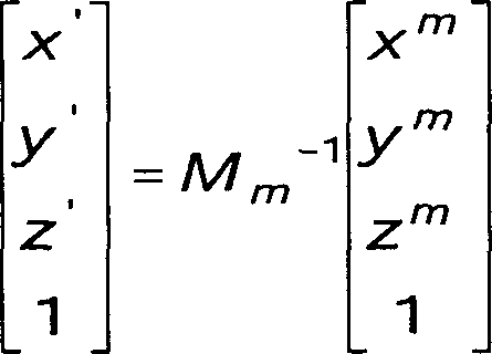
Es
ist somit möglich,
in dem sichtbaren virtuellen Koordinatensystem (O'', x''y''z'') die Koordinaten eines Punktes M als
Funktion seiner Koordinaten in dem Koordinatensystem des Spiegels
(Om, xmymzm) durch die folgende
Matrixbeziehung auszudrücken: 
Um die Position eines reellen Punktes M in dem Koordinatensystem des Spiegels (Om, xmymzm) zu bestimmen, wird die Eigenschaft verwendet, nach der das virtuelle Bild eines Punktes mit den Koordinaten (x, y, z) in einem gegebenen Koordinatensystem, wenn sich der Spiegel in der Ebene Ox, Oy erstreckt, die Koordinaten (x, y, –z) hat.In order to determine the position of a real point M in the coordinate system of the mirror (O m , x m y m z m ), the property is used, according to which the virtual image of a point with the coordinates (x, y, z) in a given coordinate system, when the mirror extends in the plane Ox, Oy, the coordinates (x, y, -z) has.
Somit
werden die Koordinaten (x'', y'', z'') des virtuellen
Bildes im sichtbaren virtuellen Koordinatensystem des Punktes M
mit den Koordinaten (x, y, z) in dem sichtbaren Koordinatensystem
durch Anwendung der folgenden Diagonalmatrix Sy erhalten: 
Die
Koordinaten (x, y, z) eines Punktes M, ausgedrückt in dem sichtbaren Koordinatensystem
(O, xyz), werden als Funktion der Koordinaten (XmymZm) desselben Punktes
in dem Koordinatensystem des Spiegels (Om,
xmymzm)
in der Form 
M0'= M0-V'·Sz, wobei M0' folglich die Übergangsmatrix des Koordinatensystems des Spiegels (Om, xmymzm) zu dem sichtbaren Koordinatensystem (O, xyz) ist.M 0 '= M 0 -V ' * S z , where M 0 'is thus the transition matrix of the coordinate system of the mirror (O m , x m y m z m ) to the visible coordinate system (O, xyz).
Um
die Koordinaten eines Punktes in dem sichtbaren Koordinatensystem
(O, xyz), ausgehend von den Koordinaten (x*, y', z')
desselben Punktes in dem Be obachtungs-Koordinatensystem (O, x'y'z'),
zu bestimmen, wird aus den Beziehungen (1) und (2) die folgende
Matrixbeziehung hergeleitet: 
Somit
ist ersichtlich, dass die zentrale Datenverarbeitungseinheit
Zusätzlich ist gemäß der Erfindung vorgesehen, dass die Anordnung der optischen Systeme und insbesondere der optischen Referenzsysteme in Bezug auf die Senkrechte des Prüfplatzes des Fahrzeuges positioniert wird.In addition is according to the invention provided that the arrangement of the optical systems and in particular of the optical reference systems in relation to the vertical of the test station of the vehicle is positioned.
Zu
diesem Zweck wird ein Bild des Spiegels
Ausgehend
von dem gespeicherten Algorithmus bestimmt die zentrale Datenverarbeitungseinheit
In
Um
zum Beispiel die relative Position der Vorderräder des Fahrzeuges zu bestimmen,
ist es vorteilhaft, die relativen Positionen der Beobachtungs-Koordinatensysteme
zu bestimmen, die den optischen Systemen
Die Übergangsmatrix zwischen dem Beobachtungs-Koordinatensystem C12 und dem sichtbaren Koordinatensystem A12 ist bekannt, da sie durch das oben erläuterte Verfahren bestimmt wird.The transition matrix between the observation coordinate system C12 and the visible one Coordinate system A12 is known as it is by the method explained above is determined.
Um
die relativen Positionen der Beobachtungs-Koordinatensysteme C12
und C14 zu bestimmen, erstellt das optische System
Diese
bestimmt in Kenntnis der geometrischen Konfiguration der Bezugspunktanordnung
der Zielscheibe
In
Kenntnis der Übergangsmatrix
von dem Beobachtungs-Koordinatensystem C12 zu dem sichtbaren Koordinatensystem
A12 und umgekehrt, bestimmt die zentrale Datenverarbeitungseinheit
Somit
bestimmt die zentrale Datenverarbeitungseinheit
Desgleichen
beobachtet das dem optischen System
Abschließend, da
das optische System
In
der Folge, analog zu dem in
Somit wird, wenn ein optisches System ein Referenzsystem wird, die Anordnung im Ganzen durch Vermessung referenziert.Consequently When an optical system becomes a reference system, the arrangement becomes as a whole referenced by surveying.
Nachdem
das Fahrzeug
Wie
in der Anmeldung WO-94/05969 beschrieben, ist jedes Rad mit einem
Target oder einem Anbau
Bevor
man zu der Bestimmung der relativen Position der Targets und folglich
der Räder
vorgeht, ist es vorteilhaft, den Umfang jedes Targets und dessen
Exzentrizität
in Betracht zu ziehen, damit die zentrale Datenverarbeitungseinheit
Ausgehend
von der gleichzeitigen Beobachtung jedes Targets
In
Kenntnis der relativen Positionen der Beobachtungs-Koordinatensysteme
der vier optischen Systeme leitet die zentrale Datenverarbeitungseinheit
Man
versteht, dass mit einer solchen Anordnung die Position der vier
optischen Systeme für
jedes Fahrzeug verändert
werden kann. Zusätzlich
ist es nicht notwendig, für
jeden Messvorgang eine feste Position zwischen den optischen Systemen
beizubehalten. Es ist einfacherweise ausreichend, dass die Einheit
Übrigens können die hier beschriebene Anordnung und das Verfahren für eine beliebige Anzahl Kameras verallgemeinert werden, bei denen sich die einen bezüglich den anderen referenzieren. Somit ist es möglich, das Fahrzeug in verschiedenen Stellungen und in verschiedenen Höhen zu vermessen.by the way can the arrangement described here and the method for any Number of cameras are generalized, where the one in terms of refer to the others. Thus, it is possible to differentiate the vehicle Positions and at different heights to measure.
Claims (7)
Applications Claiming Priority (2)
| Application Number | Priority Date | Filing Date | Title |
|---|---|---|---|
| FR9814660A FR2786267B1 (en) | 1998-11-20 | 1998-11-20 | METHOD AND DEVICE FOR DETERMINING THE POSITION OF THE OPTICAL AXIS OF A CAMERA WITH RESPECT TO A VISIBLE MARKING |
| FR9814660 | 1998-11-20 |
Publications (2)
| Publication Number | Publication Date |
|---|---|
| DE69934472D1 DE69934472D1 (en) | 2007-02-01 |
| DE69934472T2 true DE69934472T2 (en) | 2007-09-27 |
Family
ID=9533014
Family Applications (1)
| Application Number | Title | Priority Date | Filing Date |
|---|---|---|---|
| DE1999634472 Expired - Lifetime DE69934472T2 (en) | 1998-11-20 | 1999-11-16 | Determining the position of the optical axis of a camera |
Country Status (3)
| Country | Link |
|---|---|
| EP (1) | EP1003013B1 (en) |
| DE (1) | DE69934472T2 (en) |
| FR (1) | FR2786267B1 (en) |
Families Citing this family (5)
| Publication number | Priority date | Publication date | Assignee | Title |
|---|---|---|---|---|
| FR2823842B1 (en) * | 2001-04-24 | 2003-09-05 | Romain Granger | MEASURING METHOD FOR DETERMINING THE POSITION AND ORIENTATION OF A MOBILE ASSEMBLY, AND DEVICE FOR CARRYING OUT SAID METHOD |
| ES2335196T3 (en) | 2002-02-04 | 2010-03-23 | Corghi S.P.A. | DEVICE FOR MEASURING THE CHARACTERISTIC POSITION PARAMETERS OF A VEHICLE. |
| CN105757422B (en) * | 2016-04-07 | 2018-05-25 | 福建联迪商用设备有限公司 | A kind of positioner and its method for correcting the camera depth of parallelism and distance |
| DE102016220888A1 (en) | 2016-10-24 | 2018-04-26 | Micro-Epsilon Messtechnik Gmbh & Co. Kg | Reference plate and method for calibrating and / or checking a deflectometry sensor system |
| CN114637121B (en) * | 2022-03-31 | 2023-09-01 | 杭州海康威视数字技术股份有限公司 | Positioning device for camera |
Family Cites Families (4)
| Publication number | Priority date | Publication date | Assignee | Title |
|---|---|---|---|---|
| DE3143173C2 (en) * | 1981-10-30 | 1984-04-12 | Automation W + R GmbH, 8000 München | Measuring arrangement for measuring the angular position of an object to be measured using the reflection method |
| JPS63136892A (en) * | 1986-11-28 | 1988-06-09 | Nec Corp | Calibration device for camera coordinate system |
| US5444481A (en) * | 1993-01-15 | 1995-08-22 | Sanyo Machine Works, Ltd. | Method of calibrating a CCD camera |
| JPH0735644A (en) * | 1993-07-16 | 1995-02-07 | Fujitsu Ltd | Camera calibration equipment |
-
1998
- 1998-11-20 FR FR9814660A patent/FR2786267B1/en not_active Expired - Fee Related
-
1999
- 1999-11-16 DE DE1999634472 patent/DE69934472T2/en not_active Expired - Lifetime
- 1999-11-16 EP EP19990402839 patent/EP1003013B1/en not_active Expired - Lifetime
Also Published As
| Publication number | Publication date |
|---|---|
| FR2786267B1 (en) | 2001-03-30 |
| FR2786267A1 (en) | 2000-05-26 |
| EP1003013A1 (en) | 2000-05-24 |
| EP1003013B1 (en) | 2006-12-20 |
| DE69934472D1 (en) | 2007-02-01 |
Similar Documents
| Publication | Publication Date | Title |
|---|---|---|
| DE69937819T2 (en) | Optical determination of the relative positions of bodies in a room | |
| DE69826753T2 (en) | Optical profile sensor | |
| DE69428686T2 (en) | IMAGING DEVICE AND METHOD FOR DETERMINING FOCUS INFORMATION | |
| EP1497613B1 (en) | Method and device for determining the spatial co-ordinates of an object | |
| DE69213749T2 (en) | METHOD AND DEVICE FOR THE SPOTUAL MEASUREMENT OF SPACE COORDINATES | |
| DE10081029B4 (en) | Image editing to prepare a textual analysis | |
| DE10163027B4 (en) | Object location determination method and a device using this method | |
| EP2034269B1 (en) | Method and device for three-dimensional digitalising of objects | |
| DE4101921B4 (en) | Device for dynamic balancing of a motor vehicle wheel consisting of tires and rims | |
| EP1342051B1 (en) | Calibration of a measuring sensor on a coordinate measuring machine with a ball, whose center is known | |
| EP2105701B1 (en) | Method and device for determining the 3D coordinates of an object | |
| DE60133026T2 (en) | ACCURATE ALIGNMENT OF IMAGES IN DIGITAL PICTURE SYSTEMS BY ADJUSTING POINTS IN THE PICTURES | |
| EP2095068B1 (en) | Apparatus and method for increasing the measurement accuracy of digital 3d geometry measuring systems | |
| EP2574876B1 (en) | Method and device for determining the 3D coordinates of an object | |
| DE102004033114A1 (en) | Method for calibrating a distance image sensor | |
| DE4301538A1 (en) | Method and arrangement for contactless three-dimensional measurement, in particular for measuring denture models | |
| WO2005075936A1 (en) | Method for determining the position of an object in a space | |
| EP0449859B1 (en) | Process and device for observing moire patterns on test surfaces by moireing with phase shifts | |
| DE10137241A1 (en) | Arrangement, for detecting and measuring objects, optically projects markers onto object, records partial views of object in global coordinate system using information re-detected markers | |
| DE19634254B4 (en) | Optical-numerical method for determining the entire surface of a three-dimensional object | |
| EP3642560B1 (en) | System, method and marker for the determination of the position of a movable object in space | |
| WO2016146105A1 (en) | Method and device for calibrating a camera | |
| DE102008027976A1 (en) | Method and device for determining the position of a sensor | |
| DE3102880C2 (en) | Method and device for calibrating scanners | |
| DE102011012611A1 (en) | Method for contactless measurement of angle at which object is arranged relative to axis of outer reference system, involves placing object in collimated beam path of autocollimator, whose orientation is known in reference system |
Legal Events
| Date | Code | Title | Description |
|---|---|---|---|
| 8364 | No opposition during term of opposition |