Technisches GebietTechnical area
Die vorliegende Erfindung bezieht sich auf einen elektrischen Kompressor, bei welchem ein Inverterschaltkreisabschnitt, der einen Motor mit Leistung versorgt, in einem Inverteraufnahmeabschnitt installiert ist, der in einem Gehäuse ausgebildet ist.The present invention relates to an electric compressor in which an inverter circuit section that supplies a motor with power is installed in an inverter housing section formed in a case.
Technischer HintergrundTechnical background
Bisher wurde als elektrischer Kompressor, der in einer Klimaanlage für Fahrzeuge verwendet wird, ein elektrischer Kompressor mit integriertem Inverter verwendet, bei dem ein Inverterschaltkreisabschnitt in einem Inverteraufnahmeabschnitt installiert ist, der in Anbetracht der Schaltgeräusche auf der Außenoberfläche eines Gehäuses eingerichtet ist. In diesem Fall ist es außerdem erforderlich, das Volumen des Inverterschaltkreisabschnitts zu reduzieren, weil der vom Inverteraufnahmeabschnitt des elektrischen Kompressors benötigte Raum so weit wie möglich reduziert werden muss.Heretofore, as an electric compressor used in an air conditioner for vehicles, an inverter-integrated electric compressor in which an inverter circuit section is installed in an inverter housing section which is installed in consideration of switching noise on the outer surface of a case. In this case, it is also necessary to reduce the volume of the inverter circuit section because the space required by the inverter housing section of the electric compressor needs to be reduced as much as possible.
Aus diesem Grund wurde bisher ein Aufbau vorgeschlagen, bei dem eine Sammelschienenanordnung, die mit einer Platine für hohe Wärmeabstrahlung verbunden ist, auf welcher ein Leistungsschaltelement angebracht ist, und eine Steuerplatine, auf welcher ein Steuerschaltkreis angebracht ist, vorbereitet werden, wobei die Sammelschienenanordnung zwischen den beiden Platinen eingefügt und mit diesen integriert ausgeführt ist, und in diesem Zustand an einem Inverteraufnahmeabschnitt angebracht werden (siehe beispielsweise Patentdokument 1).For this reason, a structure has heretofore been proposed in which a busbar assembly, which is connected to a board for high heat radiation on which a power switching element is mounted, and a control board on which a control circuit is mounted, are prepared with the busbar assembly between the is inserted and integrated with both boards, and attached to an inverter housing portion in this state (see, for example, Patent Document 1).
Referenzliste:Reference list:
PatentdokumentPatent document
Patent Dokument 1: Japanische Patentanmeldungsveröffentlichung Nr. 2017-172509 Patent document 1: Japanese Patent Application Publication No. 2017-172509
Übersicht über die ErfindungOverview of the invention
Probleme, die durch die Erfindung zu lösen sindProblems to be solved by the invention
-
Hierbei ist dem Inverterschaltkreisabschnitt auch eine Filterformgussanordnung bereitgestellt, die elektronische Bauteile wie etwa ein Glättungskondensator zum Absorbieren hoher Frequenzkomponenten eines Schaltstroms, etc. aufweist. Weil jedoch der konventionelle Aufbau eine Struktur besitzt, bei welcher Verbindungsanschlüsse der Filterformgussanordnung durch Schrauben an dem Inverterschaltkreisabschnitt befestigt sind, ist die Verbindungsfestigkeit schwach und eine Verbesserung derselben wünschenswert.At this time, the inverter circuit section is also provided with a filter molding assembly comprising electronic components such as a smoothing capacitor for absorbing high frequency components of a switching current, etc. However, since the conventional structure has a structure in which connection terminals of the filter molding assembly are fixed to the inverter circuit portion by screws, the connection strength is weak and improvement thereof is desirable.
Die vorliegende Erfindung wurde gemacht, um die oben genannten konventionellen technischen Probleme zu lösen, und es ist ihre Aufgabe, einen elektrischen Kompressor bereitzustellen, bei welchem die Verbindungsfestigkeit zwischen einem Inverterschaltkreisabschnitt und einem mit diesem verbundenen elektrischen Schaltkreisabschnitt durch einen Verbindungsanschluss verbessert wird.The present invention has been made to solve the above-mentioned conventional technical problems, and its object is to provide an electric compressor in which connection strength between an inverter circuit portion and an electric circuit portion connected thereto by a connection terminal is improved.
Mittel zum Lösen des ProblemsMeans of solving the problem
Ein elektrischer Kompressor gemäß der vorliegenden Erfindung weist ein Gehäuse mit einem darin aufgenommen Motor, einen Inverterschaltkreisabschnitt zum Versorgen des Motors mit Leistung, und einen elektrischen Schaltkreisabschnitt mit einem Verbindungsanschluss auf, und ist dadurch gekennzeichnet, dass der Inverterschaltkreisabschnitt und der elektrische Schaltkreisabschnitt in einem Inverteraufnahmeabschnitt installiert sind, der auf einer Außenoberfläche des Gehäuses ausgebildet ist, und dass der Inverterschaltkreisabschnitt eine Invertersteuerplatine, auf welcher ein Steuerschaltkreis angebracht ist, und eine mit Harz formgegossene Hülsenanordnung aufweist, und dass die Hülsenanordnung eine Hülse, durch welche ein Stift zum Befestigen des Inverterschaltkreisabschnitts an dem Gehäuse eingesteckt ist, und einen Anschlussverbindungsabschnitt aufweist, der eine Schraube mit Außengewinde aufweist, die einen Schraubennutabschnitt besitzt, wobei beide miteinander integral in einem Zustand mit Harz formgegossen sind, in welchem der Schraubennutabschnitt hervorstehend ausgebildet ist, und dass die Invertersteuerplatine und der Verbindungsanschluss des elektrischen Schaltkreisabschnitts gemeinsam durch eine Mutter an dem Anschlussverbindungsabschnitt befestigt sind, die in den Schraubennutabschnitt eingeschraubt ist, wodurch die Invertersteuerplatine und der elektrische Schaltkreisabschnitt elektrisch miteinander verbunden sind.An electric compressor according to the present invention has a housing with a motor housed therein, an inverter circuit section for supplying the motor with power, and an electric circuit section with a connection terminal, and is characterized in that the inverter circuit section and the electric circuit section are installed in an inverter housing section which is formed on an outer surface of the housing, and that the inverter circuit section comprises an inverter control board on which a control circuit is mounted and a sleeve assembly molded with resin, and that the sleeve assembly has a sleeve through which a pin for attaching the inverter circuit section to the Housing is inserted, and has a terminal connection portion including a male screw having a screw groove portion, both of which are integral with each other in one state are molded with resin in which the screw groove portion is protruded, and that the inverter control board and the connection terminal of the electric circuit portion are fixed together by a nut to the terminal connection portion which is screwed into the screw groove portion, whereby the inverter control board and the electric circuit portion are electrically connected to each other are.
Der elektrische Kompressor der Erfindung gemäß Anspruch 2 ist dadurch gekennzeichnet, dass in oben beschriebener Erfindung die Hülsenanordnung eine Vielzahl von Anschlussverbindungsabschnitten besitzt, und die Invertersteuerplatine und ein Verbindungsanschluss, der mit einem Leiteranschluss des Motors verbunden ist, gemeinsam an jedem dieser Anschlussverbindungsabschnitte durch eine Mutter befestigt sind, die in den Schraubennutabschnitt eingeschraubt ist, wodurch die Invertersteuerplatine und der Leiteranschluss elektrisch miteinander verbunden sind.The electric compressor of the invention according to claim 2 is characterized in that, in the invention described above, the sleeve assembly has a plurality of terminal connection portions, and the inverter control board and a connection terminal connected to a lead terminal of the motor are commonly fixed to each of these terminal connection portions by a nut which is screwed into the screw groove portion, whereby the inverter control board and the lead terminal are electrically connected to each other.
Der elektrische Kompressor der Erfindung gemäß Anspruch 3 ist dadurch gekennzeichnet, dass in den oben beschriebenen Erfindungen der Inverterschaltkreisabschnitt ein integrierter Zusammenbau der Invertersteuerplatine und der Hülsenanordnung ist, dass der elektrische Schaltkreisabschnitt ein Filterschaltkreisabschnitt zum Absorbieren einer hohen Frequenzkomponente eines Schaltstroms ist, und eine Höhendimension des Filterschaltkreisabschnitts größer ist als diejenige des Inverterschaltkreisabschnitts, und dass der Inverterschaltkreisabschnitt und der Filterschaltkreisabschnitt wieder entfernbar an dem Gehäuse in einem Zustand angebracht sind, in welchem ein Teil des Filterschaltkreisabschnitts mit dem Inverterschaltkreisabschnitt überlappend ausgebildet ist.The electric compressor of the invention according to claim 3 is characterized in that, in the inventions described above, the inverter circuit portion is an integrated assembly of the inverter control board and the sleeve assembly, that the electric circuit portion is a filter circuit portion for absorbing a high frequency component of a switching current, and a height dimension of the filter circuit portion is larger than that of the inverter circuit section, and that the inverter circuit section and the filter circuit section are removably attached to the case in a state in which a part of the filter circuit section is formed to be overlapped with the inverter circuit section.
Vorteilhafte Wirkung der ErfindungAdvantageous effect of the invention
Gemäß der vorliegenden Erfindung weist in einem elektrischen Kompressor, der ein Gehäuse mit einem darin aufgenommen Motor, einen Inverterschaltkreisabschnitt zum Versorgen des Motors mit Leistung, und einen elektrischen Schaltkreisabschnitt mit einem Verbindungsanschluss aufweist, und bei welchem der Inverterschaltkreisabschnitt und der elektrische Schaltkreisabschnitt in einem Inverteraufnahmeabschnitt installiert sind, der auf einer Außenoberfläche des Gehäuses ausgebildet ist, der Inverterschaltkreisabschnitt eine Invertersteuerplatine, auf, auf welcher ein Steuerschaltkreis angebracht ist, und eine mit Harz formgegossene Hülsenanordnung aufweist, und die Hülsenanordnung besitzt eine Hülse, durch welche ein Stift zum Befestigen des Inverterschaltkreisabschnitts an dem Gehäuse eingesteckt ist, und einen Anschlussverbindungsabschnitt, der eine Schraube mit Außengewinde aufweist, die einen Schraubennutabschnitt besitzt, wobei beide miteinander integral in einem Zustand mit Harz formgegossen sind, in welchem der Schraubennutabschnitt hervorstehend ausgebildet ist. Damit einhergehend sind die Invertersteuerplatine und der Verbindungsanschluss des elektrischen Schaltkreisabschnitts gemeinsam durch eine Mutter an dem Anschlussverbindungsabschnitt befestigt, die in den Schraubennutabschnitt eingeschraubt ist, wodurch die Invertersteuerplatine und der elektrische Schaltkreisabschnitt elektrisch miteinander verbunden sind. folglich können die Invertersteuerplatine und der elektrische Schaltkreisabschnitt durch einen hochgradig festen Verbindungsaufbau miteinander verbunden werden.According to the present invention, an electric compressor comprising a housing with a motor housed therein, an inverter circuit section for supplying the motor with power, and an electric circuit section with a connection terminal, and in which the inverter circuit section and the electric circuit section are installed in an inverter housing section are formed on an outer surface of the housing, the inverter circuit portion has an inverter control board on which a control circuit is mounted and a resin molded sleeve assembly, and the sleeve assembly has a sleeve through which a pin for attaching the inverter circuit portion to the Housing is inserted, and a terminal connection portion having a male screw having a screw groove portion, both integrally molded with each other in a state with resin are cast in which the screw groove portion is formed protruding. Along with this, the inverter control board and the connection terminal of the electric circuit section are fixed together to the terminal connection section by a nut screwed into the screw groove section, whereby the inverter control board and the electric circuit section are electrically connected to each other. consequently, the inverter control board and the electric circuit section can be connected to each other by a highly rigid connection structure.
Weil insbesondere der Verbindungsanschluss des elektrischen Schaltkreisabschnitts direkt mit der Invertersteuerplatine verbunden werden kann, ist es möglich, die Kosten durch eine Reduzierung der Anzahl der Komponenten niedrig zu halten. Außerdem wird der Zusammenbau und die Entfernung von Teilen leichter als bei einer Lötverbindung, und die Hülsenanordnung und die Invertersteuerplatine sind auch integriert, indem sie aneinander durch die Mutter befestigt werden, sodass die Festigkeit der Invertersteuerplatine ebenso verbessert werden kann.In particular, since the connection terminal of the electric circuit section can be directly connected to the inverter control board, it is possible to keep the cost down by reducing the number of components. In addition, the assembly and removal of parts becomes easier than a soldered joint, and the sleeve assembly and the inverter control board are also integrated by being fixed to each other by the nut, so that the strength of the inverter control board can also be improved.
Ferner besitzt gemäß der Erfindung nach Anspruch 2 die Hülsenanordnung eine Vielzahl von Anschlussverbindungsabschnitten, und die Invertersteuerplatine und ein Verbindungsanschluss, der mit einem Leiteranschluss des Motors verbunden ist, werden miteinander an jedem der Anschlussverbindungsabschnitte durch eine Mutter befestigt, die in den Schraubennutabschnitt auf ähnliche Weise eingeschraubt wird, wodurch die Invertersteuerplatine und der Leiteranschluss elektrisch miteinander verbunden sind. Folglich kann der mit dem Leiteranschluss des Motors verbundene Verbindungsanschluss auch mit der Invertersteuerplatine mit einem hochgradig festen Verbindungsaufbau verbunden werden.Further, according to the invention of claim 2, the sleeve assembly has a plurality of terminal connecting portions, and the inverter control board and a connecting terminal connected to a lead terminal of the motor are fixed to each other at each of the terminal connecting portions by a nut screwed into the screw groove portion in a similar manner whereby the inverter control board and the conductor terminal are electrically connected to each other. Accordingly, the connection terminal connected to the lead terminal of the motor can also be connected to the inverter control board with a highly rigid connection structure.
Ferner wird gemäß der Erfindung nach Anspruch 3 der Inverterschaltkreisabschnitt als ein integrierter Zusammenbau der Invertersteuerplatine und der Hülsenanordnung hergenommen, der elektrische Schaltkreisabschnitt wird als ein Filterschaltkreisabschnitt zum Absorbieren einer hohen Frequenzkomponente eines Schaltstroms hergenommen, und wenn eine Höhendimension des Filterschaltkreisabschnitts größer ist als diejenige des Inverterschaltkreisabschnitts, sind der Inverterschaltkreisabschnitt und der Filterschaltkreisabschnitt wieder entfernbar an dem Gehäuse in einem Zustand angebracht, in welchem ein Teil des Filterschaltkreisabschnitts mit dem Inverterschaltkreisabschnitt überlappend ausgebildet ist. folglich kann ein Filterschaltkreisabschnitt, dessen Höhendimension groß ist, problemlos in dem Inverteraufnahmeabschnitt aufgenommen und darin angebracht werden, und es kann der Arbeitsvorgang des gemeinsamen Befestigens des Verbindungsanschlusses des Filterschaltkreisabschnitts (elektrischer Schaltkreisabschnitt) an dem Anschlussverbindungsabschnitt der Hülsenanordnung mit der Invertersteuerplatine und der Mutter kann ebenso leicht durchgeführt werden.Further, according to the invention of claim 3, the inverter circuit section is taken as an integrated assembly of the inverter control board and the sleeve assembly, the electric circuit section is taken as a filter circuit section for absorbing a high frequency component of a switching current, and when a height dimension of the filter circuit section is larger than that of the inverter circuit section, For example, the inverter circuit section and the filter circuit section are removably attached to the housing in a state in which a part of the filter circuit section is formed to be overlapped with the inverter circuit section. consequently, a filter circuit section, the height of which is large, can be easily received and mounted in the inverter receiving section, and the operation of jointly fixing the connection terminal of the filter circuit section (electric circuit section) to the terminal connection section of the sleeve assembly with the inverter control board and the nut can also be easily performed be performed.
FigurenlisteFigure list
-
1 ist eine vertikale seitliche Schnittansicht eines elektrischen Kompressors mit integriertem Inverter gemäß einem Ausführungsbeispiel, auf den die vorliegende Erfindung angewandt wird; 1 Fig. 13 is a vertical sectional side view of an inverter-integrated electric compressor according to an embodiment to which the present invention is applied;
-
2 ist eine Draufsicht eines Zustands, in welchem ein Deckelelement des elektrischen Kompressors abgenommen ist, betrachtet von der Seite (der einen Endseite) eines Inverteraufnahmeabschnitts; 2 Fig. 13 is a plan view of a state in which a lid member of the electric compressor is removed as viewed from the side (the one end side) of an inverter housing portion;
-
3 ist eine vergrößerte vertikale seitliche Schnittansicht eines Teils des Inverteraufnahmeabschnitts des elektrischen Kompressors aus 1; 3 FIG. 13 is an enlarged vertical side sectional view of part of the inverter housing portion of the electric compressor of FIG 1 ;
-
4 ist eine perspektivische Ansicht eines Inverterschaltkreisabschnitts des elektrischen Kompressors aus 1; 4th FIG. 13 is a perspective view of an inverter circuit portion of the electric compressor of FIG 1 ;
-
5 ist eine perspektivische Ansicht einer Rückseitenoberfläche des Inverterschaltkreisabschnitts aus 4; 5 FIG. 14 is a perspective view of a rear surface of the inverter circuit portion of FIG 4th ;
-
6 ist eine perspektivische Ansicht einer Hülsenanordnung des Inverterschaltkreisabschnitts aus 4; 6th FIG. 13 is a perspective view of a sleeve assembly of the inverter circuit portion of FIG 4th ;
-
7 ist eine perspektivische Ansicht einer Rückseitenoberfläche der Hülsenanordnung aus 6; 7th FIG. 14 is a perspective view of a rear surface of the sleeve assembly of FIG 6th ;
-
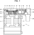
8 ist eine perspektivische Ansicht eines Anschlussverbindungsabschnitts der Hülsenanordnung aus 6; 8th FIG. 14 is a perspective view of a terminal connection portion of the sleeve assembly of FIG 6th ;
-
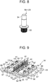
9 ist eine perspektivische Ansicht eines Leistungsmoduls des Inverterschaltkreisabschnitts aus 4; 9 FIG. 13 is a perspective view of a power module of the inverter circuit portion of FIG 4th ;
-
10 ist vertikale seitliche Schnittansicht eines Schaltelementteils des Leistungsmoduls aus 9; 10 FIG. 14 is a vertical sectional side view of a switching element part of the power module of FIG 9 ;
-
11 ist eine perspektivische Ansicht einer Installationsplatte des Leistungsmoduls aus 9; 11 FIG. 13 is a perspective view of an installation plate of the power module of FIG 9 ;
-
12 ist eine perspektivische Explosionsansicht des Leistungsmoduls aus 9; 12 FIG. 13 is an exploded perspective view of the power module of FIG 9 ;
-
13 ist eine perspektivische Explosionsansicht des Inverterschaltkreisabschnitts aus 4; 13 FIG. 13 is an exploded perspective view of the inverter circuit portion of FIG 4th ;
-
14 ist eine perspektivische Explosionsansicht eines Filterschaltkreisabschnitts des elektrischen Kompressors aus 1; 14th FIG. 13 is an exploded perspective view of a filter circuit portion of the electric compressor of FIG 1 ;
-
15 ist eine perspektivische Ansicht einer Rückseitenoberfläche des Filterschaltkreisabschnitts aus 14; 15th FIG. 14 is a perspective view of a rear surface of the filter circuit portion of FIG 14th ;
-
16 ist eine perspektivische Ansicht eines Tragelements des Filterschaltkreisabschnitts aus 14; 16 FIG. 13 is a perspective view of a support member of the filter circuit portion of FIG 14th ;
-
17 ist eine perspektivische Ansicht einer Rückseitenoberfläche des Tragelements aus 16; 17th FIG. 14 is a perspective view of a rear surface of the support member of FIG 16 ;
-
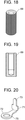
18 ist eine perspektivische Ansicht eines Mutterelements des Filterschaltkreisabschnitts aus 14; 18th FIG. 13 is a perspective view of a nut member of the filter circuit portion of FIG 14th ;
-
19 ist vertikale seitliche Schnittansicht des Mutterelements aus 18; 19th Figure 13 is a vertical side sectional view of the nut member of Figure 1 18th ;
-
20 ist eine perspektivische Ansicht eines filterseitigen Verbindungsabschlusses des Filterschaltkreisabschnitts aus 14; 20th FIG. 14 is a perspective view of a filter-side connection termination of the filter circuit portion of FIG 14th ;
-
21 ist eine perspektivische Explosionsansicht einer Filterschaltkreisplatine des Filterschaltkreisabschnitts aus 14; 21st FIG. 13 is an exploded perspective view of a filter circuit board of the filter circuit portion of FIG 14th ;
-
22 ist ein Diagramm, das einen Ablauf des Anbringens des Inverterschaltkreisabschnitts und des Filterschaltkreisabschnitts in dem Inverteraufnahmeabschnitts des elektrischen Kompressors aus 1 beschreibt; 22nd Fig. 13 is a diagram showing a procedure of mounting the inverter circuit section and the filter circuit section in the inverter housing section of the electric compressor 1 describes;
-
23 ist ein Diagramm, das einen Ablauf des Anbringens des Inverterschaltkreisabschnitts in dem Inverteraufnahmeabschnitt des elektrischen Kompressors aus 1 beschreibt; 23 Fig. 13 is a diagram showing a procedure of mounting the inverter circuit section in the inverter housing section of the electric compressor 1 describes;
-
24 ist eine vergrößerte Draufsicht des Inverteraufnahmeabschnitts an einem motorseitigen Verbindungsanschlussabschnitt des elektrischen Kompressors aus 1; 24 FIG. 13 is an enlarged plan view of the inverter housing portion at a motor-side connection terminal portion of the electric compressor 1 ;
-
25 ist eine vertikale seitliche Schnittansicht des Inverteraufnahmeabschnitts an einem motorseitigen Verbindungsanschlussabschnitt des elektrischen Kompressors aus 1; 25th FIG. 13 is a vertical sectional side view of the inverter housing portion at a motor-side connection terminal portion of the electric compressor of FIG 1 ;
-
26 ist eine Draufsicht eines motorseitigen Verbindungsanschlusses des elektrischen Kompressors aus 1; 26th FIG. 13 is a plan view of a motor-side connection port of the electric compressor of FIG 1 ;
-
27 ist ein Diagramm, das einen Ablauf des Anbringens des motorseitigen Verbindungsanschlusses des elektrischen Kompressors aus 1 beschreibt; 27 Fig. 13 is a diagram showing a procedure of attaching the motor-side connection port of the electric compressor 1 describes;
-
28 ist ein Diagramm, das einen Ablauf des Anbringens des Filterschaltkreisabschnitts in dem Inverteraufnahmeabschnitt des elektrischen Kompressors aus 1 beschreibt; 28 Fig. 13 is a diagram showing a procedure of mounting the filter circuit section in the inverter housing section of the electric compressor 1 describes;
-
29 ist ein Diagramm, das einen Ablauf des Anbringens von leistungsquellenseitigen Verbindungsanschlüssen an dem Filterschaltkreisabschnitt aus 14 beschreibt; 29 Fig. 13 is a diagram showing a procedure of attaching power source side connection terminals to the filter circuit section 14th describes;
-
30 ist eine vergrößerte Draufsicht eines Zustands, in welchem die leistungsquellenseitigen Verbindungsanschlüsse an dem Filterschaltkreisabschnitt aus 14 angebracht sind; und 30th Fig. 13 is an enlarged plan view of a state in which the power source side connection terminals on the filter circuit portion are off 14th are appropriate; and
-
31 ist eine perspektivische Ansicht des Filterschaltkreisabschnitts des Inverteraufnahmeabschnitts in dem Zustand, in welchem die in 29 gezeigten leistungsquellenseitigen Verbindungsanschlüsse angebracht sind. 31 FIG. 13 is a perspective view of the filter circuit portion of the inverter housing portion in the state in which the FIG 29 power source side connection terminals shown are attached.
Art und Weise, in welcher die Erfindung ausgeführt wirdManner in which the invention is carried out
Nachfolgend wird ein Ausführungsbeispiel der vorliegenden Erfindung im Detail mit Bezug auf die Zeichnungen beschrieben. 1 ist eine vertikale seitliche Schnittansicht eines elektrischen Kompressors 1 gemäß einem Ausführungsbeispiel, auf das die vorliegende Erfindung angewandt wird, 2 ist eine Draufsicht eines Zustands, in welchem ein Deckelelement 11 des elektrischen Kompressors 1 abgenommen ist, betrachtet von der Seite (von der einen Endseite) eines Inverteraufnahmeabschnitts 8, und 3 ist eine vergrößerte vertikale seitliche Schnittansicht eines Teils des Inverteraufnahmeabschnitts 8 des elektrischen Kompressors 1.An embodiment of the present invention will be described in detail with reference to the drawings. 1 Fig. 3 is a vertical sectional side view of an electric Compressor 1 according to an embodiment to which the present invention is applied, 2 Fig. 13 is a plan view of a state in which a lid member 11 of the electric compressor 1 is removed when viewed from the side (from the one end side) of an inverter housing section 8th , and 3 Fig. 13 is an enlarged vertical sectional side view of part of the inverter housing portion 8th of the electric compressor 1 .
Aufbau des elektrischen Kompressors 1 insgesamtConstruction of the electric compressor 1 a total of
Der elektrische Kompressor 1 gemäß dem Ausführungsbeispiel ist ein sogenannter elektrischer Kompressor mit integriertem Inverter, und bildet einen Teil eines Kältekreislaufs eine Fahrzeugklimaanlage aus, die Luft eines Fahrzeuginneren eines nicht dargestellten Fahrzeugs aufbereitet. Der elektrische Kompressor 1 weist einen Motor 6, ein Gehäuse 2, in welchem eine Kompressionsvorrichtung 7 aufgenommen ist, die durch eine Drehwelle 5 des Motors 6 anzutreiben ist, einen Inverterschaltkreisabschnitt 3, welcher den Motor 2 antreibt, und einen Filterschaltkreisabschnitt 4 als einen elektrischen Schaltkreisabschnitt zum Absorbieren einer hohen Frequenzkomponente eines Schaltstroms auf.The electric compressor 1 According to the exemplary embodiment is a so-called electric compressor with an integrated inverter, and forms part of a refrigeration circuit from a vehicle air conditioning system that processes the air in the interior of a vehicle (not shown). The electric compressor 1 has an engine 6th , a housing 2 , in which a compression device 7th is added by a rotating shaft 5 of the motor 6th is to be driven, an inverter circuit section 3 which the engine 2 drives, and a filter circuit section 4th as an electric circuit section for absorbing a high frequency component of a switching current.
Ein Inverteraufnahmeabschnitt 8, welcher an der einen Seite des Motors 6 in einer axialen Richtung der Drehwelle 5 angeordnet ist als ein Aufnahmeabschnitt dient, ist auf einer Außenoberfläche des Gehäuses 2 in dem Ausführungsbeispiel ausgebildet. Eine Öffnung 9 des Inverteraufnahmeabschnitts 8 ist durch das Deckelelement 11 verschlossen, wobei die Öffnung wieder geöffnet werden kann. Dann sind der Inverterschaltkreisabschnitt 3 und der Filterschaltkreisabschnitt 4 so ausgelegt, dass sie jeweils einzeln aus der axialen Richtung in den Inverteraufnahmeabschnitt 8 der Drehwelle 5 des Motors 6 aufgenommen werden und wieder entfernbar an dem Gehäuse 2 angebracht sind.An inverter receiving section 8th which is on one side of the engine 6th in an axial direction of the rotating shaft 5 is arranged serving as a receiving portion is on an outer surface of the housing 2 formed in the embodiment. An opening 9 of the inverter receiving section 8th is through the cover element 11 closed, whereby the opening can be opened again. Then are the inverter circuit section 3 and the filter circuit section 4th designed so that they one by one from the axial direction into the inverter receiving portion 8th the rotating shaft 5 of the motor 6th can be received and removed again from the housing 2 are attached.
Es ist anzumerken, dass die entsprechenden Figuren den elektrischen Kompressor 1 des Ausführungsbeispiels in einem Zustand illustrieren, in welchem der Inverteraufnahmeabschnitt 8 auf der oberen Seite gezeigt ist, jedoch ist der elektrische Kompressor 1 tatsächlich in einer seitlichen Richtung angeordnet, sodass der Inverteraufnahmeabschnitt 8 auf der einen Seite angeordnet ist.It should be noted that the corresponding figures show the electric compressor 1 of the embodiment in a state in which the inverter receiving portion 8th shown on the top, however, is the electric compressor 1 actually arranged in a lateral direction so that the inverter receiving portion 8th is arranged on one side.
Der Motor 6 des Ausführungsbeispiels ist aus einem 3-Phasen-Synchronmotor (einem bürstenfreien Gleichstrommotor) aufgebaut und die Kompressionsvorrichtung 7 ist beispielsweise eine Kompressionsvorrichtung vom Scroll-Typ. Die Kompressionsvorrichtung 7 wird durch die Drehwelle 5 des Motors 6 angetrieben, um ein Kühlmittel zu verdichten, wobei sie das Kühlmittel in den Kältekreislauf ausstößt. Dann wird ein Niedrigtemperaturgas-Kühlmittel aus einem Verdampfer (auch als ein Wärmeabsorber bezeichnet) angesaugt, der ebenfalls einen Teil des Kältekreislaufflusses durch das Gehäuse ausbildet. Dadurch wird das Innere des Gehäuses 2 gekühlt. Ferner ist der Inverteraufnahmeabschnitt 8 durch eine Trennwand 12 von dem Inneren des Gehäuses 2 getrennt, in welchem der Motor 6 aufgenommen ist, wobei die Trennwand 12 als eine untere Oberfläche des Inverteraufnahmeabschnitt 8 dient, und die Trennwand 12 wird ebenfalls durch das Niedrigtemperaturgas-Kühlmittel gekühlt.The motor 6th of the embodiment is composed of a 3-phase synchronous motor (a brushless DC motor) and the compression device 7th is, for example, a scroll type compression device. The compression device 7th is made by the rotating shaft 5 of the motor 6th driven to compress a refrigerant, expelling the refrigerant into the refrigeration cycle. A low temperature gas refrigerant is then drawn in from an evaporator (also referred to as a heat absorber) which also forms part of the refrigeration cycle flow through the housing. This will get the inside of the case 2 chilled. Further is the inverter receiving portion 8th through a partition 12 from the inside of the case 2 separated in which the engine 6th is added, the partition 12 as a lower surface of the inverter housing section 8th serves, and the partition 12 is also cooled by the low-temperature gas refrigerant.
Aufbau des Inverterschaltkreisabschnitts 3Structure of the inverter circuit section 3
Als nächstes wird der Aufbau des Inverterschaltkreisabschnitts 3 mit Bezug auf die 4 bis 13 erläutert. Der Inverterschaltkreisabschnitt 3 besitzt ein Leistungsmodul 14, auf welchem sechs Leistungsschaltelemente 13 (in dem Ausführungsbeispiel IGBTs) befestigt sind, die Arme der jeweiligen Phasen des 3-Phasen-Inverterschaltkreises ausbilden, eine Invertersteuerplatine 17, auf welcher ein Steuerschaltkreis 16 angebracht ist, sowie eine aus Harz gebildete Hülsenanordnung 18 mit einer Vielzahl (fünf in dem Ausführungsbeispiel) von Anschlussverbindungsabschnitten 19, 20, 21, 22 und 23.Next, the structure of the inverter circuit section 3 with reference to the 4th to 13 explained. The inverter circuit section 3 has a power module 14th on which six power switching elements 13 (IGBTs in the embodiment) are attached forming arms of the respective phases of the 3-phase inverter circuit, an inverter control board 17th on which a control circuit 16 is attached, and a sleeve assembly formed of resin 18th having a plurality (five in the embodiment) of terminal connection portions 19th , 20th , 21st , 22nd and 23 .
Der Inverterschaltkreisabschnitt 3 wandelt eine von einer Batterie eines hier nicht dargestellten Fahrzeugs gelieferte Gleichspannungsleistung (DC) in eine dreiphasige Wechselspannungsleistung (AC) um, um diese Leistung einer Statorspule 27 des Motors 6 zuzuführen. Daher sind Verbindungspunkte zwischen den Leistungsschaltelementen 13 auf einer Seite des oberen Arms jeder Phase und den Leistungsschaltelementen 13 auf einer Seite des unteren Arms derselben jeweils entsprechend mit Leiteranschlüssen 24, 25 und 26 verbunden, die sich aus der Trennwand 12 des Gehäuses 2 heraus erstrecken und in der axialen Richtung vermittels dreier motorseitiger Verbindungsanschlüsse (Verbindungsanschlüsse) 28 hervorstehen. Leistungsquellenanschlüsse der Leistungsschaltelemente 13 auf der Seite des oberen Arms und Masseanschlüsse der Leistungsschaltelemente 13 auf der Seite des unteren Arms sind mit einem Leistungsquellen-Kabelstrang von der oben erwähnten Batterie über den Filterschaltkreisabschnitt 4 und einen Verbinder (HV-verbinder) 29 für hohe Leistungen verbunden.The inverter circuit section 3 converts a direct voltage power (DC) supplied by a battery of a vehicle (not shown here) into a three-phase alternating voltage power (AC) in order to convert this power to a stator coil 27 of the motor 6th feed. Therefore, there are connection points between the power switching elements 13 on one side of the upper arm of each phase and the power switching elements 13 on one side of the lower arm of the same in each case with conductor connections 24 , 25th and 26th connected emerging from the partition 12 of the housing 2 extend out and in the axial direction by means of three motor-side connection terminals (connection terminals) 28 protrude. Power source connections of the power switching elements 13 on the side of the upper arm and ground connections of the power switching elements 13 on the lower arm side are connected to a power source harness from the above-mentioned battery via the filter circuit section 4th and a connector (HV connector) 29 for high performance.
In diesem Fall erstrecken sich die Leiteranschlüsse 24 bis 26, die jeweils mit dem Verbindungspunkt zwischen dem Leistungsschaltelement 13 auf der Seite des oberen Arms jeder Phase und dem Leistungsschaltelement 13 auf der Seite des unteren Arms derselben verbunden sind, durch die Trennwand 12, um mit der Statorspule 27 des Motors 6 in dem Gehäuse 2 verbunden zu werden. Ferner sind die Leistungsquellenanschlüsse und die Masseanschlüsse elektrisch mit dem Leistungsquellen-Kabelstrang über den Filterschaltkreisabschnitt 4, die leistungsquellenseitigen Verbindungsanschlüsse (Verbindungsanschlüsse) 31, die jeweils an den führenden Enden von zwei Leitungen 98 vorgesehen sind, die sich aus dem vorerwähnten Hochleistungsverbinder 29 heraus erstrecken, und den Hochleistungsverbinder 29 usw. verbunden.In this case, the conductor connections extend 24 to 26th each with the connection point between the power switching element 13 on the side of the upper arm of each phase and the power switching element 13 on the side of the lower arm thereof are connected by the partition wall 12 to go with the stator coil 27 of the motor 6th in the case 2 to be connected. Furthermore, the power source terminals and the Ground connections electrically to the power source harness through the filter circuit section 4th , the power source-side connection terminals (connection terminals) 31 each at the leading ends of two lines 98 are provided, resulting from the aforementioned high-performance connector 29 extend out, and the heavy duty connector 29 etc. connected.
Aufbau der Hülsenanordnung 18Structure of the sleeve assembly 18
Als nächstes wird der Aufbau der Hülsenanordnung 18 mit Bezug auf die 6 bis 8 erläutert. Die vorerwähnten fünf Anschlussverbindungsabschnitte 19, 20, 21, 22 und 23 stehen von der Hülsenanordnung 18 hervor, und die Hülsenanordnung 18 besitzt ferner sechs Hülsen 32. Jeder der Anschlussverbindungsanschlüsse 19, 20, 21, 22 und 23 ist aus einer aus Metall hergestellten Schraube mit Außengewinde wie in dem Ausführungsbeispiel der 8 gezeigt gebildet und besitzt einen eingebetteten Abschnitt 33 (welcher einen Schraubenkopf ausbildet) mit feinen Unebenheiten, die auf dessen Außenoberfläche gebildet sind, sowie einen Schraubennutabschnitt 34, der von dem eingebetteten Abschnitt 34 hervorsteht. Ferner ist die Hülse 32 aus einem Metallzylinder mit einer vorbestimmten Längendimension hergestellt.Next up is building the sleeve assembly 18th with reference to the 6th to 8th explained. The aforementioned five terminal connection sections 19th , 20th , 21st , 22nd and 23 stand by the sleeve assembly 18th out, and the sleeve assembly 18th also has six sleeves 32 . Each of the port connection terminals 19th , 20th , 21st , 22nd and 23 is made of a screw made of metal with an external thread as in the embodiment of FIG 8th shown formed and has an embedded portion 33 (which forms a screw head) having fine asperities formed on the outer surface thereof and a screw groove portion 34 that of the embedded section 34 protrudes. Furthermore, the sleeve 32 made of a metal cylinder with a predetermined length dimension.
Weiters sind diese Anschlussverbindungsabschnitte 19 bis 23 und die Hülse 32 integral mit der Hülsenanordnung 18 formvergossen, indem sie mit einem isolierenden Hartharz umspritzt werden. Dabei werden die eingebetteten Abschnitte 33 der entsprechenden Anschlussverbindungsabschnitte 19 bis 23 in dem Hartharz der Hülsenanordnung 18 eingebettet, und die Schraubennut 34 befindet sich in einem Zustand, in welchem sie nach oben von der Oberfläche der Hülsenanordnung 18 hervorsteht. Außerdem sind die Anschlussverbindungsabschnitte 19 bis 21 an Positionen auf der Seite der Leiteranschlüsse 24 bis 26 angeordnet, und die Anschlussverbindungsabschnitte 22 und 23 sind an Positionen auf der Seite des Filterschaltkreisabschnitts 4 angeordnet. Ferner ist jede Hülse 32 in einem Abschnitt der Hülsenanordnung 18 angeordnet und besitzt obere und untere Enden, die in Bezug auf die Oberfläche der Hülsenanordnung 18 und deren Rückseite frei und geöffnet liegen, und sie ermöglicht es einen Stift 36 für das Befestigen an dem Gehäuse 2, wie nachfolgend beschrieben ist, da hindurch gesteckt zu werden.Furthermore, these are terminal connection sections 19th to 23 and the sleeve 32 integral with the sleeve assembly 18th molded by overmoulding them with an insulating hard resin. In doing so, the embedded sections 33 of the corresponding terminal connection sections 19th to 23 in the hard resin of the sleeve assembly 18th embedded, and the screw groove 34 is in a state in which it is upwardly from the surface of the sleeve assembly 18th protrudes. In addition, the terminal connection sections are 19th to 21st at positions on the side of the conductor terminals 24 to 26th arranged, and the terminal connecting portions 22nd and 23 are at positions on the side of the filter circuit section 4th arranged. Furthermore, each sleeve is 32 in a portion of the sleeve assembly 18th arranged and has upper and lower ends with respect to the surface of the sleeve assembly 18th and its back is exposed and open, and it allows a pen 36 for attaching to the housing 2 as described below to be plugged through.
Außerdem sind drei Positionierungsstifte 37 in Bezug auf die Invertersteuerplatine 17 hervorstehend und integral durch ein Hartharz an vorbestimmten Positionen auf der Oberfläche der Hülsenanordnung 18 ausgebildet. Des Weiteren sind vier Positionierungsstifte 38 in Bezug auf das Leistungsmodul 14 hervorstehend und integral durch ein Hartharz an vorbestimmten Positionen auf der Rückseitenoberfläche der Hülsenanordnung 18 ausgebildet. Ferner sind zwei Positionierungsstifte 39 in Bezug auf das Gehäuse 2 hervorstehend und integral durch ein Hartharz an vorbestimmten Positionen auf der Rückseitenoberfläche der Hülsenanordnung 18 ausgebildet.There are also three positioning pins 37 in relation to the inverter control board 17th protruding and integral with a hard resin at predetermined positions on the surface of the sleeve assembly 18th educated. There are also four positioning pins 38 in relation to the power module 14th protruding and integral by a hard resin at predetermined positions on the rear surface of the sleeve assembly 18th educated. There are also two positioning pins 39 in terms of the housing 2 protruding and integral by a hard resin at predetermined positions on the rear surface of the sleeve assembly 18th educated.
Ferner sind Einstecklöcher 42, die Anschlüsse 41 für Source, Emitter und Drain der entsprechenden Leistungsschaltelemente 13, die an dem Leistungsmodul 14 angebracht sind, dazu veranlassen, durch sie hindurch zu treten, in einer Vielzahl (an 18 Stellen) in dem mittleren Teil der Hülsenanordnung 18 gebildet. Damit hat, wie nachfolgend beschrieben wird, die Hülsenanordnung 18 eine vorbestimmte Dickendimension, die allein ausreicht, zumindest einen Isolationsabstand (den kürzesten Isolationsabstand) zwischen der Invertersteuerplatine 17 und dem Leistungsmodul 14 (eine nachfolgend zu beschreibende Installationsplatte 43) zu gewährleisten.There are also insertion holes 42 who have favourited connections 41 for source, emitter and drain of the corresponding power switching elements 13 that are attached to the power module 14th are arranged to cause them to pass through in a plurality (at 18 locations) in the central portion of the sleeve assembly 18th educated. Thus, as will be described below, the sleeve assembly 18th a predetermined thickness dimension sufficient alone, at least one insulation distance (the shortest insulation distance) between the inverter control board 17th and the power module 14th (an installation plate to be described below 43 ) to guarantee.
Aufbau des Leistungsmoduls 14Structure of the power module 14
Der Aufbau des Leistungsmoduls 14 wird mit Bezug auf die 9 bis 12 erläutert. Das Leistungsmodul 14 wird dadurch gebildet, dass sechs Leistungsschaltelemente 13 auf der Installationsplatte 43 angebracht werden, die aus einer Metallplatte (Aluminium in dem Ausführungsbeispiel) mit einer hohen Wärmeabstrahlung gebildet wird. In diesem Fall sind in der Installationsplatte 43 drei auf drei Einpasslöcher 44 in vorbestimmten Abständen untereinander vorgesehen, welche eine Gesamtzahl zu sechs in zwei Reihen ergeben sich durch sie hindurch erstrecken, und es sind senkt Buchungsabschnitte 46 vorgesehen, die jeweils entsprechend als Ausnehmung in die Oberflächen der entsprechenden Einpasslöcher 44 ausgebildet sind.The structure of the power module 14th is referring to the 9 to 12 explained. The power module 14th is formed by having six power switching elements 13 on the installation plate 43 which is formed from a metal plate (aluminum in the embodiment) with high heat radiation. In this case are in the installation plate 43 three to three fitting holes 44 provided at predetermined distances from one another, which result in a total of six in two rows extending through them, and there are low accounting sections 46 provided, each correspondingly as a recess in the surfaces of the corresponding fitting holes 44 are trained.
Dann wird eine Schraube mit Außengewinde 47 in jedes der Einpasslöcher 44 von der Seite der Rückseitenoberfläche derselben her press-eingepasst und darin fixiert und vertikal auf der Installationsplatte 43 angeordnet. Bei jeder Schraube mit Außengewinde 47 steht ein Schraubennutabschnitt 48 derselben von der Fläche der Installationsplatte 43 in dem angepassten Zustand hervor, und ein jedes einer Anzahl von Harzüberzug-Materialien 49 wird auf der Außenoberfläche der Schraube mit Außengewinde 47 in einem Abschnitt außerhalb des Schraubennutabschnitts 48 der Schraube mit Außengewinde 47 einschließlich des Senkbohrungsabschnitts 46 in Formguß ausgebildet. Dabei bedecken die Harzüberzug-Materialien 49 jeweils die Schraube mit Außengewinde 47 in einem Zustand, in welchem die Schraubennutabschnitte 48 der Schraube mit Außengewinde 47 freiliegen (11).Then a screw with an external thread 47 in each of the fitting holes 44 press-fitted and fixed therein from the side of the back surface thereof and vertically on the installation board 43 arranged. With every screw with an external thread 47 stands a screw groove section 48 same from the face of the installation plate 43 in the fitted state, and each of a number of resin coating materials 49 is on the outside surface of the screw with external thread 47 in a section outside of the screw groove section 48 the screw with external thread 47 including the counterbore portion 46 formed in casting. Thereby cover the resin coating materials 49 each screw with an external thread 47 in a state in which the screw groove portions 48 the screw with external thread 47 exposed ( 11 ).
Auf der anderen Seite sind die Leistungsschaltelement 13 jeweils mit Durchgangslöchern 51 ausgebildet. Dann wird jedes Leistungsschaltelement auf der Installationsplatte 43 (seiner Oberfläche) vermittels einer isolierende Folie 52 mit einer Form angeordnet, die es jeder Schraube mit Außengewinde 47 ermöglicht, durch das Durchgangsloch 51 hindurch zu treten. In diesem Fall sind zwei isolierende Folien 52 in der Form verwendet, um sich über die Leistungsschaltelemente 13 jeder Reihe hinweg zu erstrecken. Jede isolierende Folie 52 ist ferner mit 3 zu 3 Durchgangslöchern 53 ausgebildet. Jede Schraube mit Außengewinde 47 tritt durch das Durchgangsloch 53 der isolierende Folie 52 und das Durchgangsloch 51 des Leistungsschaltelements 13 hindurch, und der Schraubennutabschnitt 48 steht von dem Leistungsschaltelement 13 hervor.On the other hand are the power switching element 13 each with through holes 51 educated. Then each circuit switching element is on the installation board 43 (its surface) by means of an insulating film 52 arranged with a shape that it is each screw with external thread 47 allows through the through hole 51 to step through. In this case there are two insulating foils 52 in the form used to find out about the power switching elements 13 across each row. Any insulating film 52 is also with 3 to 3 through holes 53 educated. Each screw with an external thread 47 enters through the through hole 53 the insulating film 52 and the through hole 51 of the power switching element 13 therethrough, and the screw groove portion 48 stands from the power switching element 13 emerged.
Ferner sind die Anschlüsse 41 der Leistungsschaltelemente 13 jeder Reihe in dem Zustand, in welchem die entsprechenden Leistungsschaltelemente 13 auf der Installationsplatte 43 angeordnet sind, in dem mittleren Teil der Erziehungsplatte 43 benachbart zueinander und so gebogen, dass sie in eine Aufwärtsrichtung von der Installation statt 43 gerichtet sind (in einer Richtung derart, dass sie von deren Oberfläche weg aufsteigen). In diesem Zustand wird eine Mutter 54 auf den Schraubennutabschnitt 48 jeder Schraube mit Außengewinde 47 aufgeschraubt, um dabei jedes Leistungsschaltelement 13 an der Installationsplatte 43 zu befestigen und zu fixieren, sodass das Leistungsmodul 14 ausgebildet ist. In diesem Zustand ist das Harzüberzug-Material 49 zwischen dem Leistungsschaltelement 13 und der isolierenden Folie 52 und der Schraube mit Außengewinde 47 zwischenliegend angeordnet (10).Furthermore, the connections 41 the power switching elements 13 each row in the state in which the corresponding power switching elements 13 on the installation plate 43 are arranged in the central part of the education plate 43 adjacent to each other and bent so that they face in an upward direction from the installation instead of 43 (in a direction such that they rise away from the surface thereof). In this state becomes a mother 54 on the screw groove section 48 each screw with an external thread 47 unscrewed to do each power switching element 13 on the installation plate 43 to attach and fix so that the power module 14th is trained. The resin coating material is in this state 49 between the power switching element 13 and the insulating film 52 and the screw with an external thread 47 arranged in between ( 10 ).
Übrigens wird dann, wenn die Mutter 54 über das Gewinde mit der Schraube mit Außengewinde 47 in Angriff tritt, eine vorbestimmte Schablone verwendet, um jedes Leistungsschaltelement 13 daran zu hindern, sich zu drehen. Somit sind sechs Schraube mit Außengewinden 47, die aufrecht auf der Installationsplatte 43 vorgesehen sind, sowie die jeweils die Schraube mit Außengewinden 47 in einem Zustand überziehenden Harzüberzug-Materialien 49 vorgesehen, in welchem die Schraubennutabschnitte 48 der Schraube mit Außengewinden 47 freiliegen. Die Leistungsschaltelemente 13 und die isolierende Folie 52 sind auf der Installationsplatte 43 in dem Zustand angeordnet, in welchem die Schraube mit Außengewinden 47 da hindurchgetreten sind, und durch die Muttern 54 an der Installationsplatte 43 befestigt sind, die in die Schraubennutabschnitte 48 geschraubt sind, sodass die entsprechenden Leistungsschaltelemente 13 auf der Installationsplatte 43 über die isolierende Folie 52 angebracht sind, wodurch das Leistungsmodul 14 ausgebildet ist. Somit führt jede Schraube mit Außengewinde 47 einen Auftrag aus, dass Leistungsschaltelement 13 und die isolierende Folie 52 relativ zu der Installationsplatte 43 zu positionieren.Incidentally, if the mother will 54 via the thread with the screw with external thread 47 When attacked, a predetermined template is used to design each power switching element 13 from turning. So there are six screws with external threads 47 standing upright on the installation plate 43 are provided, as well as each the screw with external threads 47 in a state of coating resin coating materials 49 provided in which the screw groove sections 48 the screw with external threads 47 exposed. The power switching elements 13 and the insulating film 52 are on the installation plate 43 arranged in the state in which the screw with external threads 47 stepped through there, and through the nuts 54 on the installation plate 43 are fastened into the screw groove sections 48 are screwed so that the corresponding power switching elements 13 on the installation plate 43 over the insulating film 52 are attached, making the power module 14th is trained. Thus, every screw with an external thread leads 47 an order from that circuit breaker 13 and the insulating film 52 relative to the installation plate 43 to position.
Somit kann auch eine Verkleinerung der Größe erzielt werden, weil die Durchführbarkeit des Zusammenbaus beträchtlich verbessert wird, und speziell eingerichtete Positioniermittel ebenfalls nicht mehr benötigt werden. Insbesondere kann auch eine Isolation zwischen der Schraube mit Außengewinde 47 und dem Leistungsschaltelement 13 ohne weitere Hindernisse sichergestellt werden, weil das Harzüberzug-Material 49 zwischen dem Leistungsschaltelement 13 und der isolierenden Folie 52 und der Schraube mit Außengewinde 47 in dem Zustand zwischenliegend angeordnet ist, in welchem diese an der Installationsplatte 43 durch die Muttern 54 fixiert sind.Thus, a reduction in size can also be achieved because the feasibility of assembly is considerably improved and specially designed positioning means are also no longer required. In particular, there can also be insulation between the screw with an external thread 47 and the power switching element 13 can be ensured without further obstacles because of the resin coating material 49 between the power switching element 13 and the insulating film 52 and the screw with an external thread 47 is interposed in the state in which it is attached to the installation plate 43 through the nuts 54 are fixed.
Weil in dem Ausführungsbeispiel insbesondere jede Schraube mit Außengewinde 47 an der Installationsplatte 43 presseingepasst und fixiert ist, und weil das Harzüberzug-Material 49 an der Außenoberfläche der Schraube mit Außengewinde 47 mit Formguß angeformt ist, ist es möglich, eine weitere Verbesserung in der Durchführbarkeit des Zusammenbaus zu erzielen und sogar einen signifikanten Beitrag bei einer Verbesserung der Raumeinsparung zu erhalten.Because in the exemplary embodiment, in particular, each screw with an external thread 47 on the installation plate 43 is press-fitted and fixed, and because the resin coating material 49 on the outer surface of the screw with an external thread 47 is formed with molding, it is possible to make a further improvement in assembling feasibility and even make a significant contribution to an improvement in space saving.
Übrigens sind in dem Randabschnitt der Installationsplatte 43 fünf Einstecklöcher 56 an Positionen entsprechend den vorbestimmten Hülsen 32 der oben beschriebenen Hülsenanordnung 18 ausgebildet. Ferner sind sechs Positionierlöcher 57 in hindurchtretender Weise an den Positionen entsprechend den Positionierstiften 38 und 39 ausgebildet, die auf der Rückseitenoberfläche der Hülsenanordnung 18 ausgebildet sind.Incidentally, are in the edge portion of the installation plate 43 five insertion holes 56 at positions corresponding to the predetermined sleeves 32 the sleeve assembly described above 18th educated. There are also six positioning holes 57 in a penetrating manner at the positions corresponding to the positioning pins 38 and 39 formed on the rear surface of the sleeve assembly 18th are trained.
Aufbau der Invertersteuerplatine 17Structure of the inverter control board 17
Der Steuerschaltkreis 16 der Invertersteuerplatine 17 führt eine Schaltsteuerung jedes der Leistungsschaltelemente 13 des Leistungsmoduls 14 abhängig von externen Befehlen durch. Ferner besitzt der Steuerschaltkreis eine Funktion des Übermittelns eines Antriebszustands des Motors 6 nach außen, und ist so aufgebaut, dass jede Schaltkreiskomponente wie etwa ein Mikrocomputer über eine gedruckte Leitung verbunden ist.The control circuit 16 the inverter control board 17th performs switching control of each of the power switching elements 13 of the power module 14th depending on external commands. Further, the control circuit has a function of transmitting a driving state of the engine 6th to the outside, and is constructed so that each circuit component such as a microcomputer is connected through a printed circuit.
Ferner sind in dem Randabschnitt der Invertersteuerplatine 17 fünf Anschlussverbindungslöcher 58 an Positionen entsprechend den Anschlussverbindungsabschnitten 19, 20, 21, 22 und 23 der oben beschriebenen Hülsenanordnung 18 ausgebildet. Zusätzlich sind acht Einstecklöcher 59 in dem Randabschnitt der Invertersteuerplatine 17 einschließlich Positionen entsprechend den jeweiligen Hülsen 32 der Hülsenanordnung 18 ausgebildet. Darüber hinaus sind drei Positionierlöcher 61 in hindurchtretender Weise an Positionen jeweils entsprechend den Positionierstiften 37 ausgebildet, die auf der Oberfläche der Hülsenanordnung 18 ausgebildet sind. Zusätzlich ist eine Vielzahl von Anschlussverbindungslöchern 62 (an 18 Stellen) sogar auch an Positionen entsprechend den jeweiligen Einstecklöchern 42 der Hülsenanordnung 18 ausgebildet.Also in the edge portion are the inverter control board 17th five connector connection holes 58 at positions corresponding to the terminal connection sections 19th , 20th , 21st , 22nd and 23 the sleeve assembly described above 18th educated. There are also eight insertion holes 59 in the edge portion of the inverter control board 17th including positions corresponding to the respective sleeves 32 the sleeve assembly 18th educated. There are also three positioning holes 61 in a penetrating manner at positions corresponding to the positioning pins, respectively 37 formed on the surface of the sleeve assembly 18th are trained. In addition, there are a variety of terminal connection holes 62 (in 18 places) even in positions corresponding to the respective insertion holes 42 the sleeve assembly 18th educated.
Ablauf des Zusammenbaus des InverterschaltkreisabschnittsFlow of assembling the inverter circuit section
Ein Ablauf des Zusammenbaus des Inverterschaltkreisabschnitts 3 wird als nächstes mit Bezug auf obigen Aufbau erläutert. Übrigens integriert der Inverterschaltkreisabschnitt 3 die Invertersteuerplatine 17, die Hülsenanordnung 18 und das Leistungsmodul 14 in einer Seitenlinie der Fertigung. Hierbei wird als erstes - wie in 13 gezeigt ist - die Invertersteuerplatine 17, auf welcher der Steuerschaltkreis 16 angebracht ist, als die obere Seite genommen, das Leistungsmodul 14, auf welchem die Leistungsschaltelemente 13 angebracht sind, wird als die untere Seite genommen, und die Invertersteuerplatine 17, die Hülsenanordnung 18 und das Leistungsmodul 14 werden eines nach dem anderen in einem Zustand gestapelt, bei welchem die Hülsenanordnung 18 zwischen der Invertersteuerplatine 17 und dem Leistungsmodul 14 zwischenliegend angeordnet ist.A flow of assembling the inverter circuit section 3 will next be explained with reference to the above structure. Incidentally, the inverter circuit section integrates 3 the inverter control board 17th , the sleeve assembly 18th and the power module 14th in a sideline of manufacturing. First - as in 13 shown - the inverter control board 17th on which the control circuit 16 attached, taken as the top side, is the power module 14th on which the power switching elements 13 attached is taken as the bottom side, and the inverter control board 17th , the sleeve assembly 18th and the power module 14th are stacked one by one in a state that the sleeve assembly 18th between the inverter control board 17th and the power module 14th is arranged in between.
Dabei fügen sich die Positionierstifte 37 auf der Oberfläche der Hülsenanordnung 18 in die Positionierlöcher 61 der Invertersteuerplatine 17 ein und stehen von der Invertersteuerplatine 17 hervor. Die Positionierstifte 38 und 39 auf der Rückseitenoberfläche der Hülsenanordnung 18 treten entsprechend in die Positionierlöcher 57 des Leistungsmoduls 14 ein und stehen von dem Leistungsniveau 14 hervor, sodass die Positionen der drei Teile mit hoher Genauigkeit festgelegt werden kann.The positioning pins fit together 37 on the surface of the sleeve assembly 18th into the positioning holes 61 the inverter control board 17th and are available from the inverter control board 17th emerged. The positioning pins 38 and 39 on the back surface of the sleeve assembly 18th step into the positioning holes accordingly 57 of the power module 14th one and stand by the level of performance 14th so that the positions of the three parts can be determined with high accuracy.
In diesem gestapelten Zustand korrespondiert jedes Einsteckloch 56 des Leistungsmoduls 14 mit der Seite der fünf Hülsen 32 zur Rückseitenoberfläche der Hülsenanordnung 18 hin. Die sechs Einstecklöcher 59 der Invertersteuerplatine 17 korrespondieren mit der Seite jeder Hülse 32 zur (vorderen) Oberfläche der Hülsenanordnung 18 hin. Auch treten die Anschlussverbindungsabschnitte 19 bis 23, die in der Hülsenanordnung 18 vorgesehen sind, durch die Anschlussverbindungslöcher 58 hindurch, die in der Invertersteuerplatine 17 ausgebildet sind, und stehen auf der Seite der Oberfläche der Invertersteuerplatine 17 hervor. Ferner treten die Anschlüsse 41 der entsprechenden Leistungsschaltelemente 13 des Leistungsmoduls 14 durch die entsprechenden Einstecklöcher 42 der Hülsenanordnung 18 hindurch und stehen geringfügig von den Anschlussverbindungslöchern 62 der Invertersteuerplatine 17 auf der Seite der Oberfläche der Invertersteuerplatine 17 hervor.In this stacked state, each insertion hole corresponds 56 of the power module 14th with the side of the five pods 32 to the rear surface of the sleeve assembly 18th down. The six insertion holes 59 the inverter control board 17th correspond to the side of each sleeve 32 to the (front) surface of the sleeve assembly 18th down. The terminal connection sections also occur 19th to 23 that are in the sleeve assembly 18th are provided through the terminal connection holes 58 through that in the inverter control board 17th are formed and stand on the side of the surface of the inverter control board 17th emerged. There are also connections 41 the corresponding power switching elements 13 of the power module 14th through the corresponding insertion holes 42 the sleeve assembly 18th through and slightly protrude from the terminal connection holes 62 the inverter control board 17th on the side of the surface of the inverter control board 17th emerged.
In diesem Zustand werden die von der Invertersteuerplatine 17 hervorstehenden Positionierungsstifte 37 und jeder der von dem Leistungsmodul 14 hervorstehenden Positionierstifte 38 wärmeverstemmt, wodurch der Invertersteuerabschnitt 17, die Hülsenanordnung 18, und das Leistungsmodul 14 integral miteinander verbunden werden. Ferner wird der Anschluss 41 des Leistungsschaltelements 13, der von dem Anschlussverbindungsloch 62 hervor steht, an den Invertersteuerschaltkreis 17 gelötet, um das Leistungsschaltelement 13 und die Invertersteuerplatine 17 elektrisch miteinander zu verbinden.In this state, the inverter control board 17th protruding positioning pins 37 and each of those from the power module 14th protruding positioning pins 38 stalked, thereby causing the inverter control section 17th , the sleeve assembly 18th , and the power module 14th be integrally connected to each other. Furthermore, the connection 41 of the power switching element 13 from the terminal connection hole 62 protrudes to the inverter control circuit 17th soldered to the power switching element 13 and the inverter control board 17th to connect electrically to each other.
Durch dieses Wärmeverstemmen und Löten werden die Invertersteuerplatine 17, die Hülsenanordnung 18, und das Leistungsmodul 14 in einer Seitenlinie untereinander integriert hergestellt (4 und 5). Weil hierbei die aus Harz hergestellte Hülsenanordnung 18 eine vorbestimmte Dickendimension besitzt, dient die Hülsenanordnung 18 als ein Abstandhalter, der zwischen dem Invertersteuerblock 17 und dem Leistungsmodul 14 zwischen liegend angeordnet ist. Der Isolationsabstand zwischen dem Invertersteuerabschnitt 17 und dem Leistungsmodul 14 ist dadurch auch bei kürzestem Abstand gewährleistet.This heat staking and soldering becomes the inverter control board 17th , the sleeve assembly 18th , and the power module 14th produced in a sideline integrated with each other ( 4th and 5 ). Because here the sleeve assembly made of resin 18th has a predetermined thickness dimension, the sleeve assembly is used 18th as a spacer between the inverter control block 17th and the power module 14th is arranged between lying. The isolation distance between the inverter control section 17th and the power module 14th is guaranteed even with the shortest distance.
Wie oben beschrieben sind die Positionierstifte 37 und 38 für das Positionieren relativ zur Invertersteuerplatine 17 und dem Leistungsmodul 14 auf der Hülsenanordnung 18 vorgesehen, und die Positionierstifte 37 und 38 werden wärmeverstemmt, wobei die Hülsenanordnung 18 zwischen der Invertersteuerplatine 17 und dem Leistungsmodul 14 zwischenliegt, wodurch die Invertersteuerplatine 17, die Hülsenanordnung 18, und das Leistungsmodul 14 integriert ausgeführt werden. Dadurch wird das Erfordernis gesonderter Befestigungsmittel wie etwa Schrauben zum Integrieren der Invertersteuerplatine 17, der Hülsenanordnung 18, und des Leistungsmoduls 14 des Inverterschaltkreisabschnitt 3 vermieden und eine Reduzierung der Anzahl der Bauteile und eine Reduzierung des Gewichts ermöglicht.The positioning pins are as described above 37 and 38 for positioning relative to the inverter control board 17th and the power module 14th on the sleeve assembly 18th provided, and the positioning pins 37 and 38 are caulked with the sleeve assembly 18th between the inverter control board 17th and the power module 14th interposed, making the inverter control board 17th , the sleeve assembly 18th , and the power module 14th be carried out integrated. This eliminates the need for separate fasteners such as screws to integrate the inverter control board 17th , the sleeve assembly 18th , and the power module 14th of the inverter circuit section 3 avoided and allows a reduction in the number of components and a reduction in weight.
Des Weiteren ist es dadurch, dass die Befestigungsmittel wie etwa Schrauben nicht verwendet werden, nicht weiter notwendig, einen Isolationsabstand derselben sicherzustellen, und es wird sogar möglich, zu einem Downsizing des Inverterschaltkreisabschnitts 3 beizutragen. Weil ferner die aus Harz hergestellte Hülsenanordnung 18 zwischen der Invertersteuerplatine 17 dem Leistungsmodul 14 im integrierten Zustand zwischenliegend angeordnet ist, ist es sichergestellt, dass der Isolationsabstand zwischen der Invertersteuerplatine 17 und dem Leistungsmodul 14 am kürzesten ist. Weil außerdem der Einfluss der von dem Leistungsschaltelement 13 des Leistungsmoduls 14 erzeugten Wärme auf die Invertersteuerplatine 17 durch die aus Harz hergestellte Hülsenanordnung 18 blockiert werden kann, wird durch diese eine weitere Miniaturisierung ermöglicht.Furthermore, since the fastening means such as screws are not used, it is no longer necessary to ensure an insulation distance thereof, and it even becomes possible to downsize the inverter circuit section 3 to contribute. Furthermore, because the sleeve assembly made of resin 18th between the inverter control board 17th the power module 14th is arranged between them in the integrated state, it is ensured that the insulation distance between the inverter control board 17th and the power module 14th is the shortest. In addition, because of the influence of the power switching element 13 of the power module 14th generated heat to the inverter control board 17th by the sleeve assembly made of resin 18th can be blocked, this enables further miniaturization.
Dann wird die Hülsenanordnung 18 mit den Anschlussverbindungsabschnitten 19 bis 23, die aus den Schraube mit Außengewinden mit den Schraubennuten 34 gebildet sind, und den Hülsen 32 versehen, in welche die Stifte 36 zum Befestigen des Inverterschaltkreisabschnitts 3 an dem Gehäuse 2 wie nachfolgend beschrieben eingefügt werden, und die Anschlussverbindungsabschnitte 19 bis 23 und die Hülse 32 werden integral miteinander mit Harz formvergossen, wobei die Schraubennutabschnitte 34 hervorstehend ausgebildet werden. Dadurch erhält die Hülsenanordnung 18 und der Inverterschaltkreisabschnitt 3 eine Struktur, die eine hohe Festigkeit besitzt, wodurch es möglich wird, die Vibrationsbeständigkeit zu verbessern.Then the sleeve assembly 18th with the terminal connection sections 19th to 23 that come from the screw with external threads with the screw grooves 34 are formed, and the sleeves 32 provided in which the pins 36 for fixing the inverter circuit section 3 on the housing 2 as described below, and the terminal connecting sections 19th to 23 and the sleeve 32 are molded integrally with each other with resin with the screw groove portions 34 are formed protruding. This preserves the sleeve assembly 18th and the inverter circuit section 3 a structure having high strength, making it possible to improve vibration resistance.
Aufbau des Filterschaltkreisabschnitts 4Structure of the filter circuit section 4
Als nächstes wird der Aufbau des Filterschaltkreisabschnitts 4 mit Bezug auf die 14 bis 21 erläutert. Der Filterschaltkreisabschnitt 4 wird aus einer Filterschaltkreisplatine 66 als eine Steuerplatine, auf welcher elektronische Bauteile wie etwa ein relativ großer Glättungskondensator (Elektrolytkondensator) 63, der zwischen dem Leistungsquellenanschluss und dem Installationsanschluss des 3-Phasen-Inverterschaltkreises verschaltet ist, eine Spule 64, die ebenfalls echt groß ist, und die mit dem Leistungsquellenanschluss verbunden ist, etc., angebracht sind, und aus einem Tragelement 67 gebildet, das aus einem Hartharz hergestellt ist, und das den Kondensator 63 und die Spule 64 (elektrische Bauteile) in sich aufnimmt.Next is the construction of the filter circuit section 4th with reference to the 14th to 21st explained. The filter circuit section 4th becomes from a filter circuit board 66 as a control board on which electronic components such as a relatively large smoothing capacitor (electrolytic capacitor) 63 connected between the power source terminal and the installation terminal of the 3-phase inverter circuit, a coil 64 which is also really large and which is connected to the power source terminal, etc., are attached, and a support member 67 which is made of a hard resin and which constitutes the capacitor 63 and the coil 64 (electrical components) in itself.
Aufbau des Tragelements 67Structure of the support element 67
Das Tragelement 67 besitzt eine Oberfläche, die offen ist, und besitzt eine Behälterform mit einer Tiefendimension, die ausreicht, den Glättungskondensator 63 und die Spule 64 aufzunehmen, die wie oben beschrieben groß sind. In einem Randabschnitt des Tragelements 67 sind fünf Hülsen 68 die jeweils eine vorbestimmte Längendimension besitzen und aus einem Metallzylinder hergestellt sind, integral mit dem Tragelement 67 durch Umspritzung mit einem isolierenden Hartharz formgegossen, wobei sie auf den vorderen und hinteren Oberflächen des Tragelements 67 freiliegen und offen hergestellt sind. Außerdem sind zwei taschenförmige Metall-Mutterelemente 69 mit auf deren Außenoberflächen ausgebildeten feinen Unebenheiten wie in den 18 und 19 gezeigt an der einen Endseite des Tragelements 67 auf ähnliche Weise integral mit dem Tragelement 67 mit Harz formvergossen, wobei sie auf der Oberfläche des Tragelements 67 freiliegen und offen ausgebildet sind. Dabei werden die entsprechenden Mutterelemente 69 in vorbestimmten Abständen voneinander eingerichtet.The support element 67 has a surface that is open and has a tank shape with a depth dimension sufficient to the smoothing capacitor 63 and the coil 64 which are large as described above. In an edge section of the support element 67 are five pods 68 each having a predetermined length dimension and made of a metal cylinder integral with the support member 67 molded by overmolding with an insulating hard resin, placing them on the front and rear surfaces of the support element 67 exposed and made open. There are also two pocket-shaped metal nut elements 69 with fine unevenness formed on their outer surfaces as in the 18th and 19th shown on one end side of the support element 67 similarly integral with the support member 67 molded with resin, placing them on the surface of the support element 67 are exposed and open. The corresponding nut elements are thereby 69 set up at predetermined intervals from one another.
Ferner sind zwei Führungsabschnitte 76 an der Kante des Tragelements 67 an einer Position ausgebildet, die jedem Mutterelement 69 entspricht, sodass sie hohlförmig zur Innenseite hin ausgebildet sind. Die Führungsabschnitte der 76 besitzen einen vorbestimmten Abstand voneinander. Wie nachfolgend beschrieben ist, wird, während Positionsverschiebungen eingeschränkt werden, wenn die zwei leistungsquellenseitigen Verbindungsanschlüsse 31 elektrisch mit der Filterschaltkreisplatine 66 verbunden werden, ein Isolationsabstand zwischen den leistungsquellenseitigen Verbindungsanschlüssen 31 sichergestellt.There are also two guide sections 76 at the edge of the support element 67 formed at a position corresponding to each nut member 69 corresponds, so that they are designed to be hollow towards the inside. The guide portions of Fig. 76 are spaced a predetermined distance apart. As will be described below, while positional shifts are restricted when the two power source side connection terminals 31 electrically to the filter circuit board 66 are connected, an insulation distance between the power source side connection terminals 31 ensured.
Ferner sind auf die gleiche Weise zwei filterseitige Verbindungsanschlüsse Verbindungsanschlüsse) 71 integral auf der anderen Endseite des Tragelement 67 mit Harz formvergossen. Jeder filterseitige Verbindungsanschluss 71 besitzt einen Flachplatten-Anschlussabschnitt 72 mit einem darin festgelegten Loch 75, wie es in 20 gezeigt ist, und einen Lötabschnitt 73, der in einem rechten Winkel von dem Flachplatten-Anschlussabschnitt 72 weggebogen ist. Der Flachplatten-Anschlussabschnitt 72 steht seitlich von dem Tragelement 67 hervor, und der Lötabschnitt 73 ist in dem Tragelement 67 eingebettet, um von dessen oberer Oberfläche vorzustehen. Des Weiteren ist ein Positionierstift 74 so ausgebildet, dass er von der Oberfläche des Tragelements 67 hervorsteht.Further, in the same manner, two filter-side connection terminals are connection terminals 71 integrally on the other end side of the support member 67 molded with resin. Any filter-side connection port 71 has a flat plate connection section 72 with a hole set in it 75 as it is in 20th and a soldering portion 73 that is at a right angle from the flat plate connector section 72 is bent away. The flat plate connector section 72 stands to the side of the support element 67 emerge, and the soldered portion 73 is in the support element 67 embedded to protrude from its upper surface. There is also a positioning pin 74 formed so that it is from the surface of the support element 67 protrudes.
Aufbau der Filterschaltkreisplatine 66Structure of the filter circuit board 66
Die elektronischen Bauteile wie etwa der Glättungskondensator 63, die Spule 64, etc. sind auf der Seite der Rückseitenoberfläche der Filterschaltkreisplatine 66 angebracht. Ferner sind vier Einstecklöcher 77 in dem Randabschnitt der Filterschaltkreisplatine 66 an Positionen ausgebildet, die den Hülsen 68 des Tragelements 67 wie oben beschrieben entsprechen. Zwei Anschlussverbindungslöcher 78 sind an einer Endseite der Filterschaltkreisplatine 66 jeweils an Positionen ausgebildet, die den Mutterelementen 69 des Tragelements 67 entsprechen. Des Weiteren sind zwei Anschlussverbindungslöcher 79 jeweils auf der anderen Endseite der Filterschaltkreisplatine 66 an Positionen ausgebildet, die den filterseitigen Verbindungsanschlüssen 71 des Tragelements 67 entsprechen.The electronic components such as the smoothing capacitor 63 , the sink 64 , etc. are on the side of the rear surface of the filter circuit board 66 appropriate. There are also four insertion holes 77 in the edge portion of the filter circuit board 66 formed at positions corresponding to the sleeves 68 of the support element 67 as described above. Two port connection holes 78 are on one end side of the filter circuit board 66 each formed at positions corresponding to the nut members 69 of the support element 67 correspond. There are also two port connection holes 79 each on the other end of the filter circuit board 66 formed at positions corresponding to the filter-side connection terminals 71 of the support element 67 correspond.
Ablauf des Zusammenbaus des Filterschaltkreisabschnitts 4Flow of assembling the filter circuit section 4
Als nächstes wird der Ablauf des Zusammenbaus des Filterschaltkreisabschnitts 4 gemäß dem oben beschriebenen Aufbau erläutert. Übrigens integriert auch der Filterschaltkreisabschnitt 4 die Filterschaltkreisplatine 66 und das Tragelement 67 in einer Seitenlinie der Fertigung. Hierbei werden als erstes, wie in 21 gezeigt ist, der Glättungskondensator 64 und die Spule 64 der Filterschaltkreisplatine 66 auf der unteren Seite platziert, und diese werden in dem Tragelement 67 aufgenommen.Next is the flow of assembling the filter circuit section 4th explained according to the structure described above. Incidentally, the filter circuit section is also integrated 4th the filter circuit board 66 and the support element 67 in a sideline of manufacturing. First, as in 21st shown is the smoothing capacitor 64 and the coil 64 the filter circuit board 66 placed on the lower side, and these are in the support element 67 recorded.
Hierbei fügen sich die Lötabschnitte 73 der filterseitigen Verbindungsanschlüsse 71 jeweils in die Anschlussverbindungslöcher 79 der Filterschaltkreisplatine 66 ein und stehen geringfügig von der Filterschaltkreisplatine 66 hervor, und die Einstecklöcher 77 entsprechen jeweils den Hülsen 68 des Tragelements 67. Ferner entsprechen die Anschlussverbindungslöcher 78 der Filterschaltkreisplatine 66 jeweils den Mutterelementen 69 des Tragelements 67.This is where the soldered sections fit together 73 the filter-side connection connections 71 each into the connection connection holes 79 the filter circuit board 66 and are slightly off the filter circuit board 66 and the insertion holes 77 correspond to the sleeves 68 of the support element 67 . Furthermore, the terminal connection holes correspond 78 the filter circuit board 66 each of the mother elements 69 of the support element 67 .
In diesem Zustand werden die Filterschaltkreisplatine 66 und das Tragelement 67 durch Auffüllen des Tragelements 67 mit einem wärmehärtenden Harz 81 (zum Beispiel ein Epoxidharz, das in 3 gezeigt ist) miteinander integriert. Ferner wird der Lötabschnitt 73 des filterseitigen Verbindungsanschlusses 71, der von dem jeweiligen Anschlussverbindungsloch 79 hervorsteht, an die Filterschaltkreisplatine 66 angelötet, um mit der Filterschaltkreisplatine 66 elektrisch verbunden zu werden. Die Filterschaltkreisplatine 66 und das Tragelement 67 werden in einer Seitenlinie der Fertigung durch Auffüllen des wärmewartenden Harzes 81 und Löten wie beschrieben integriert (14 und 15). Hierbei ist das untere Ende der Hülse 68 (das Ende auf der Seite des Gehäuses 2) in der Mitte in der Höhenrichtung des Filterschaltkreisabschnitts 4 oder in einem Bereich nahe der Mitte positioniert (3).In this state, the filter circuit board 66 and the support element 67 by filling the support element 67 with a thermosetting resin 81 (for example an epoxy resin found in 3 is shown) integrated with each other. Furthermore, the soldering portion 73 of the filter-side connection port 71 from the respective terminal connection hole 79 protruding to the filter circuit board 66 soldered to with the filter circuit board 66 to be electrically connected. The filter circuit board 66 and the support element 67 are in a sideline of manufacturing by filling up the heat-waiting resin 81 and soldering integrated as described ( 14th and 15th ). Here is the lower end of the sleeve 68 (the end on the side of the case 2 ) in the middle in the height direction of the filter circuit section 4th or positioned in an area near the center ( 3 ).
Somit sind die Filterschaltkreisplatine 66 und das Tragelement 67 durch Auffüllen des Tragelements 67 mit dem wärmehärtenden Harz 81 in der Seitenlinie der Fertigung in dem Zustand miteinander integriert, in welchem der Glättungskondensator 63 und die Spule 64 in das Tragelement 67 des Filterschaltkreisabschnitts 4 aufgenommen sind. Die filterseitigen Verbindungsanschlüsse 71, deren eine Enden an die Filterschaltkreisplatine 66 angelötet sind, und deren andere Enden elektrisch mit dem mit dem Anschlussverbindungsabschnitten 22 und 23 (Schraube mit Außengewinden) und Muttern 92 des Inverterschaltkreisabschnitts 3 verbunden sind, wie nachfolgend beschrieben wird, sind integral mit dem Tragelement 67 mit Harz formvergossen. Folglich werden das Auffüllen mit Harz und das Löten durchgeführt, bevor das Gehäuse 2 zusammengebaut wird, und zum Zeitpunkt des Zusammenbaus braucht nur noch das Schrauben der Muttern 92 und das Befestigen der Stifte 36 durchgeführt werden, sodass die Durchführbarkeit des Zusammenbaus signifikant verbessert wird. Ferner wird der filterseitige Verbindungsanschluss 71, dessen eines Ende an die Filterschaltkreisplatine 66 angelötet ist, integral mit dem Tragelement 67 mit Harz formvergossen, sodass eine Struktur mit hoher Beständigkeit gegenüber Vibrationen erhalten wird, und es werden keine mechanischen Spannungen in dem Lötabschnitt erzeugt, auch nachdem der Filterschaltkreisabschnitt 4 an dem Gehäuse 2 befestigt wurde.Thus are the filter circuit board 66 and the support element 67 by filling the support element 67 with the thermosetting resin 81 integrated with each other in the sideline of manufacture in the state in which the smoothing capacitor 63 and the coil 64 in the support element 67 of the filter circuit section 4th are included. The filter-side connection connections 71 one end of which to the filter circuit board 66 are soldered, and the other ends thereof are electrically connected to that with the terminal connecting portions 22nd and 23 (Screw with external thread) and nuts 92 of the inverter circuit section 3 as will be described below are integral with the support member 67 molded with resin. Thus, resin filling and soldering are performed before the housing 2 is assembled, and at the time of assembly all that remains is to screw the nuts 92 and attaching the pins 36 can be performed so that assembling workability is significantly improved. Furthermore, the filter-side connection terminal 71 one end of which to the filter circuit board 66 is soldered, integral with the support element 67 molded with resin so that a structure having high resistance to vibration is obtained and no stress is generated in the soldering portion even after the filter circuit portion 4th on the housing 2 was attached.
(4) Ablauf des Anbringens des Inverterschaltkreisabschnitt 3 und des Filterschaltkreisabschnitt 4 an dem Gehäuse 2(4) Procedure for attaching the inverter circuit section 3 and the filter circuit section 4th on the housing 2
Als nächstes wird ein Ablauf des Anbringens des Inverterschaltkreisabschnitt 3 und des Filterschaltkreisabschnitt 4 an dem Gehäuse 2 in einer Hauptlinie der Fertigung mit Bezug auf die 22 und 23 erläutert. Wie in den 22 und 23 gezeigt ist, wird das Gehäuse 2 mit der einen Endseite in der axialen Richtung der Drehwelle 5 des Motors 6 ausgerichtet, in welcher der Inverteraufnahmeabschnitt 8 so ausgelegt ist, dass er nach oben gewandt ist. Dann werden der Inverterschaltkreisabschnitt 3 und der Filterschaltkreisabschnitt 4, die wie oben beschrieben miteinander in der Seitenlinie der Fertigung integriert wurden, jeweils getrennt voneinander aus der axialen Richtung (von oben) im Inverteraufnahmeabschnitt 8 des Gehäuses 2 auf ähnliche Weise aufgenommen.Next, a procedure of attaching the inverter circuit section will be described 3 and the filter circuit section 4th on the housing 2 in a main line of manufacturing with respect to the 22nd and 23 explained. As in the 22nd and 23 shown is the case 2 with the one end side in the axial direction of the rotating shaft 5 of the motor 6th aligned in which the inverter receiving portion 8th is designed to face up. Then the inverter circuit section 3 and the filter circuit section 4th which have been integrated with one another in the manufacturing sideline as described above, each separated from one another from the axial direction (from above) in the inverter receiving portion 8th of the housing 2 recorded in a similar manner.
Hierbei sind zwei Positionierausnehmungen 82 in der Trennwand 12 des Gehäuses 2, die als die Bodenfläche für den Inverteraufnahmeabschnitt 8 dient, an Positionen ausgebildet, die den Positionierstiften 39 des Inverterschaltkreisabschnitts 3 jeweils entsprechen. Acht Stiftbefestigungsausnehmungen 83 sind an Positionen entsprechend den Einstecklöchern 59 der Invertersteuerplatine 17 des Inverterschaltkreisabschnitts 3 ausgebildet. Wenn dann jeder Positionierstift 39 in die entsprechende Positionierausnehmung 82 eingefügt wird, ist die Position des Inverterschaltkreisabschnitt 3 relativ zu dem Gehäuse 2 festgelegt, und in diesem Zustand entsprechen die Einstecklöcher 59 (die Hülsen 32 der Hülsenanordnung 18, die Einstecklöcher 56 des Leistungsmoduls 14) jeweils den Stiftbefestigungsausnehmungen 83 (22).There are two positioning recesses 82 in the partition 12 of the housing 2 used as the bottom surface for the inverter receiving section 8th serves, formed at positions that the positioning pins 39 of the inverter circuit section 3 each correspond. Eight pin mounting recesses 83 are at positions corresponding to the insertion holes 59 the inverter control board 17th of the inverter circuit section 3 educated. If then every positioning pin 39 into the corresponding positioning recess 82 is inserted is the position of the inverter circuit section 3 relative to the housing 2 is set, and in this state, the insertion holes correspond 59 (the pods 32 the sleeve assembly 18th who have favourited the insertion holes 56 of the power module 14th ) each of the pin mounting recesses 83 ( 22nd ).
Weil in diesem Zustand die Installationsplatte 53 des Leistungsmoduls 14 die Trennwand 12 wie in 3 gezeigt kontaktiert, befindet sich das Leistungsschaltelement 13 in einer Wärmeaustauschbeziehung mit der Trennwand 12 durch die Installationsbach 43, und wird somit durch ein Niedrigtemperaturgas-Kühlmittel gekühlt. Übrigens bezeichnet in 3 das Bezugszeichen 96 eine Auslegung, die in der Trennwand 12 ausgebildet ist, um dem wärmeverstemmten Positionierstift 38 eine Ausweichmöglichkeit zu bieten, und das Bezugszeichen 97 bezeichnet eine Ausnehmung, die in der Trennwand 12 gebildet ist, um dem Kopf der Schraube mit Außengewinde 47 der Installationsplatte 43 eine Ausweichmöglichkeit zu bieten.Because in this state the installation plate 53 of the power module 14th the partition 12 as in 3 contacted, the power switching element is located 13 in a heat exchange relationship with the partition 12 through the Installationsbach 43 , and is thus cooled by a low-temperature gas refrigerant. Incidentally, denoted in 3 the reference number 96 a design included in the bulkhead 12 is designed around the heat-staked positioning pin 38 to offer an alternative, and the reference number 97 denotes a recess in the partition 12 is formed around the head of the screw with an external thread 47 the installation plate 43 to offer an alternative.
Auf der anderen Seite sind in der Trennwand 12 des Gehäuses 2 zwei Positionierausnehmungen 84 jeweils an Positionen ausgebildet, die den Positionierstiften 74 des Filterschaltkreisabschnitts 4 entsprechen. Zwei Stiftbefestigungsausnehmungen 86 sind an Positionen entsprechend den zwei Einstecklöchern 77 (Hülsen 68) an Positionen des Filterschaltkreises 4 auf der Seite ausgebildet, die dem Inverterschaltkreisabschnitt 3 gegenüberliegt. Wenn dann jeder Positionierstifte 74 in die Positionierausnehmung 84 eingeführt wird, ist die Position des Filterschaltkreises 4 in Bezug auf das Gehäuse 2 festgelegt. Somit können der Filterschaltkreisabschnitt 4 und das Gehäuse 2 leicht positioniert werden, indem das Tragelement 67 mit dem Positionierstiften 74 für das Gehäuse 2 versehen wird.On the other hand are in the partition 12 of the housing 2 two positioning recesses 84 each formed at positions corresponding to the positioning pins 74 of the filter circuit section 4th correspond. Two pin mounting recesses 86 are at positions corresponding to the two insertion holes 77 (Pods 68 ) at positions of the filter circuit 4th formed on the side facing the inverter circuit section 3 opposite. If then any positioning pins 74 into the positioning recess 84 is the position of the filter circuit 4th in terms of the housing 2 set. Thus, the filter circuit section 4th and the case 2 can be easily positioned by the support element 67 with the positioning pins 74 for the housing 2 is provided.
Hierbei entsprechen die zwei Einstecklöcher 77 (Hülsen 68) an den Positionen auf der dem Inverterschaltkreisabschnitt 3 gegenüberliegenden Seite jeweils den Stiftbefestigungsausnehmungen 86, und jede Hülse 68 kontaktiert das Gehäuse (Trennwand 12) (3). Demgegenüber ist ein Teil des oberen Kantenabschnitts des Tragelements 67 auf derjenigen Seite des Filterschaltkreisabschnitts 4 zum Inverterschaltkreisabschnitt 3 hin im Überlapp mit dem Inverterschaltkreisabschnitt 3 ausgebildet, und die zwei Einstecklöcher (Hülsen 68) auf der Seite zum Inverterschaltkreisabschnitt 3 hin entsprechen jeweils den zwei Einstecklöchern 59 des Inverterschaltkreisabschnitts 3 (22).The two insertion holes correspond here 77 (Pods 68 ) at the positions on the inverter circuit section 3 opposite side each the pin mounting recesses 86 , and every sleeve 68 contacts the housing (partition 12 ) ( 3 ). In contrast, is part of the upper edge portion of the support element 67 on that side of the filter circuit section 4th to the inverter circuit section 3 to overlap with the inverter circuit section 3 formed, and the two insertion holes (sleeves 68 ) on the inverter circuit section side 3 each correspond to the two insertion holes 59 of the inverter circuit section 3 ( 22nd ).
Weil hierbei der Glättungskondensator 64 und die Spule 64 des Filterschaltkreisabschnitts 4 wie oben beschrieben relativ groß sind, wird auch eine Höhendimension H1 des Filterschaltkreisabschnitts 4 größer als eine Höhendimension H2 des Inverterschaltkreisabschnitts 3, wie in 3 gezeigt ist. Jedoch kann - wie im Ausführungsbeispiel - durch wieder entfernbares Anbringen des Inverterschaltkreisabschnitts 3 und des Filterschaltkreisabschnitts 4 an dem Gehäuse 2 einschließlich des Teils des Filterschaltkreisabschnitts 4, der mit dem Inverterschaltkreisabschnitt 3 überlappend ausgebildet ist, der Filterschaltkreisabschnitt 4 mit großer Höhendimension problemlos in dem Inverteraufnahmeabschnitt 8 aufgenommen und darin angebracht werden.Because here the smoothing capacitor 64 and the coil 64 of the filter circuit section 4th are relatively large as described above, there will also be a height dimension H1 of the filter circuit section 4th greater than one height dimension H2 of the inverter circuit section 3 , as in 3 is shown. However, as in the exemplary embodiment, by attaching the inverter circuit section in a removable manner 3 and the filter circuit section 4th on the housing 2 including the portion of the filter circuit section 4th that is associated with the inverter circuit section 3 is formed overlapping, the filter circuit section 4th with a large height dimension easily in the inverter receiving portion 8th be taken up and attached.
Ferner kann auch, wie nachfolgend beschrieben wird, die Arbeit des miteinander verbindenden Befestigens der filterseitigen Verbindungsanschlüsse 71 des Filterschaltkreisabschnitt 4 (elektrischer Schaltkreisabschnitt) mit den Anschlussverbindungsabschnitten 22 und 23 der Hülsenanordnung 18 einschließlich der Invertersteuerplatine 17 und der Muttern 92 leicht durchgeführt werden.Further, as will be described below, the work of connecting the filter-side connection terminals to each other can also be performed 71 of the filter circuit section 4th (electrical circuit section) with the terminal connection sections 22nd and 23 the sleeve assembly 18th including the inverter control board 17th and the nuts 92 easily done.
Im Übrigen stoßen dabei die den zwei Einstecklöchern 59 entsprechenden Hülsen 32 an dem Gehäuse 2 (Trennwand 12) an (3). Ferner entsprechen die Flachplatten-Anschlussabschnitte 72 der filterseitigen Verbindungsanschlüsse 71 des Filterschaltkreisabschnitts 4 jeweils den Anschlussverbindungsabschnitten 22 und 23 des Inverterschaltkreisabschnitts 3, und jeder der Anschlussverbindungsabschnitte 22 und 23 erhält eine Form, mit der sie in das Loch 75 des Flachplatten-Anschlussabschnitts 72 des eingefügt werden.Incidentally, this is where the two insertion holes come into play 59 corresponding sleeves 32 on the housing 2 (Partition wall 12 ) on ( 3 ). Furthermore, the flat-plate terminal sections correspond 72 the filter-side connection connections 71 of the filter circuit section 4th each of the terminal connection sections 22nd and 23 of the inverter circuit section 3 , and each of the terminal connection sections 22nd and 23 gets a shape with which to put it in the hole 75 of the flat-plate connection section 72 des to be inserted.
Nachdem der Inverterschaltkreisabschnitt 3 und der Filterschaltkreisabschnitt 4 in dieser Weise in den Inverteraufnahmeabschnitt 8 angeordnet wurden, werden die Stifte 36 in die Einstecklöcher 59 (Hülsen 32 und Einstecklöcher 56) des Inverterschaltkreisabschnitt 3 und die Einstecklöcher 77 (Hülsen 68) des Filterschaltkreisabschnitts 4 aus der axialen Richtung (von oben) (23) eingesteckt, jeweils in die Stiftbefestigungsausnehmungen 83 und 86 geschraubt, und dann befestigt, wodurch der Inverterschaltkreisabschnitt 3 und der Filterschaltkreisabschnitt 4 wieder entfernbar an dem Gehäuse 2 angebracht sind (2 und 3). In diesem Zustand befinden sich die jeweiligen Anschlussverbindungsabschnitte 19, 20 und 21 des Inverterschaltkreisabschnitts 3 benachbart zu den jeweiligen Leiteranschlüssen 24, 25 und 26, und stehen in derselben axialen Richtung (nach oben) hervor wie die Leiteranschlüsse 24, 25 und 26.After the inverter circuit section 3 and the filter circuit section 4th in this way into the inverter receiving section 8th have been arranged, the pins 36 into the insertion holes 59 (Pods 32 and insertion holes 56 ) of the inverter circuit section 3 and the insertion holes 77 (Pods 68 ) of the filter circuit section 4th from the axial direction (from above) ( 23 ) inserted into the pin mounting recesses 83 and 86 screwed, and then fixed, creating the inverter circuit section 3 and the filter circuit section 4th removable again on the housing 2 are appropriate ( 2 and 3 ). The respective terminal connection sections are in this state 19th , 20th and 21st of the inverter circuit section 3 adjacent to the respective conductor connections 24 , 25th and 26th , and protrude in the same axial direction (upward) as the lead terminals 24 , 25th and 26th .
(5) Ablauf des Verbindens der entsprechenden Verbindungsanschlüsse 28, 31 und 71(5) Flow of connecting the respective connection terminals 28 , 31 and 71
Als nächstes wird der Ablauf des Verbindens des motorseitigen Verbindungsanschlusses 28, des leistungsquellenseitigen Verbindungsanschlusses 31 und des filterseitigen Verbindungsanschlusses 71 (welche alle Verbindungsanschlüsse sind), die oben beschrieben sind, mit Bezug auf die 24 bis 31 erläutert. Der motorseitige Verbindungsanschluss 28 ist aus einer Metallplatte hergestellt, und besitzt, wie in 26 gezeigt ist, einen Flachplatten-Anschlussabschnitt 88 mit einem Loch 87, das auf der einen Endseite festgelegt ist, sowie einen Druckkontakt-Anschlussabschnitt 89 mit einer vorbestimmten Elastizität auf der anderen Endseite.Next, the procedure of connecting the motor-side connection terminal will be described 28 , of the power source-side connection port 31 and the filter-side connection port 71 (which are all connection terminals) described above with reference to FIG 24 to 31 explained. The motor-side connection port 28 is made of a metal plate and has, as in 26th is shown, a flat plate connector portion 88 with a hole 87 fixed on one end side and a pressure contact terminal portion 89 with a predetermined elasticity on the other end side.
Dann werden die drei motorseitigen Verbindungsanschlüsse 28 aus der axialen Richtung (von oben) des Gehäuses 2 in den Inverteraufnahmeabschnitt 8 gesteckt, und die Leiteranschlüsse 24, 25 und 26 werden jeweils entsprechend in die Druckkontakt-Anschlussabschnitte 89 der motorseitigen Verbindungsanschlüsse 28 press-eingepasst. Infolgedessen wird der Druckkontakt-Anschlussabschnitt 89 jedes motorseitigen Verbindungsanschlusses 28 entsprechend gegen jeden der Leiteranschlüsse 24 bis 26 gedrückt und elektrisch mit diesem verbunden. Ferner sind die Anschlussverbindungsabschnitte 19, 20 und 21 so eingerichtet, dass sie in die Löcher 87 der Flachplatten-Anschlussabschnitte 88 eingefügt werden, sodass die motorseitigen Verbindungsanschlüsse 28 jeweils entsprechend zwischen dem Leiteranschluss 24 und dem Anschlussverbindungsabschnitt 19, zwischen dem Leiteranschluss 25 und den Anschlussverbindungsabschnitt 20, und zwischen dem Leiteranschluss 26 und dem Anschlussverbindungsabschnitt 21 angebracht werden.Then the three motor-side connection terminals 28 from the axial direction (from above) of the housing 2 into the inverter receiving section 8th plugged in, and the conductor connections 24 , 25th and 26th are each correspondingly in the pressure contact connection sections 89 the motor-side connection connections 28 press-fitted. As a result, the pressure contact terminal portion becomes 89 each motor-side connection port 28 accordingly against each of the conductor connections 24 to 26th pressed and electrically connected to it. Furthermore, the terminal connection sections are 19th , 20th and 21st set them up in the holes 87 the flat plate connection sections 88 inserted so that the motor-side connection terminals 28 each corresponding between the conductor connection 24 and the terminal connecting portion 19th , between the conductor connection 25th and the terminal connecting portion 20th , and between the conductor connection 26th and the terminal connecting portion 21st be attached.
In diesem Zustand wird die Mutter 91 in den Schraubennutabschnitt 34 von jedem der Anschlussverbindungsabschnitte 19 bis 21 von oben eingeschraubt, um dabei den Flachplatten-Anschlussabschnitt 88 jedes motorseitigen Verbindungsanschlusses 28 zwischen der Mutter 91 und der Invertersteuerplatine 17 zwischenliegend einzuklemmen, wodurch der Flachplatten-Anschlussabschnitt 88 und die Invertersteuerplatine 17 aneinander befestigt werden. Infolgedessen ist jeder motorseitige Verbindungsanschluss 28 entsprechend an jedem der Anschlussverbindungsabschnitte 19 bis 21 über die Invertersteuerplatine 17 befestigt. Auf diese Weise ist jeder motorseitige Verbindungsanschluss 28 an der Invertersteuerplatine 17 fixiert und elektrisch mit dieser verbunden, und die Leiteranschlüsse 24 bis 26 von dem Motor 6 sind elektrisch mit der Invertersteuerplatine 17 durch die motorseitigen Verbindungsanschlüsse 28 verbunden.In this state becomes the mother 91 into the screw groove section 34 from each of the terminal connection sections 19th to 21st screwed in from above, thereby removing the flat plate connection section 88 each motor-side connection port 28 between the mother 91 and the inverter control board 17th clamped in between, whereby the flat-plate connection section 88 and the inverter control board 17th be attached to each other. As a result, each motor side is a connection port 28 correspondingly at each of the terminal connection sections 19th to 21st via the inverter control board 17th attached. In this way, every motor-side connection port is 28 on the inverter control board 17th fixed and electrically connected to this, and the conductor connections 24 to 26th from the engine 6th are electrical with the inverter control board 17th through the connection connections on the motor side 28 connected.
Ferner werden die Muttern 92 jeweils in die entsprechenden Schraubennutabschnitte 34 der Anschlussverbindungsabschnitt 22 und 23 des Inverterschaltkreisabschnitt 3 von oben eingeschraubt, und dabei die Flachplatten-Anschlussabschnitte 72 der filterseitigen Verbindungsanschlüsse 71 zwischen den Muttern 92 und der Invertersteuerplatine 17 zwischenliegend eingeklemmt, wodurch die Flachplatten-Anschlussabschnitte 72 und die Invertersteuerplatine 17 aneinander befestigt werden. Somit sind die filterseitigen Verbindungsanschlüsse 71 an der Invertersteuerplatine 17 fixiert und elektrisch mit dieser verbunden, und die Filterschaltkreisplatine 66 des Filterschaltkreisabschnitts 4 ist elektrisch mit der Invertersteuerplatine 17 über die filterseitigen Verbindungsanschlüsse 71 verbunden.Furthermore, the nuts 92 each in the corresponding screw groove sections 34 the terminal connection section 22nd and 23 of the inverter circuit section 3 screwed in from above, with the flat plate connection sections 72 the filter-side connection connections 71 between the nuts 92 and the inverter control board 17th sandwiched between, whereby the flat plate connection sections 72 and the inverter control board 17th be attached to each other. The filter-side connection connections are thus 71 on the inverter control board 17th fixed and electrically connected to this, and the filter circuit board 66 of the filter circuit section 4th is electrical with the inverter control board 17th via the filter-side connection connections 71 connected.
Auf diese Weise sind die Invertersteuerplatine 17 und die filterseitigen Verbindungsanschluss 71 des Filterschaltkreisabschnitts 4 durch die Muttern 92, die jeweils in den entsprechenden Schraubennutabschnitt 34 eingeschraubt wurden, verbindend an den Anschlussverbindungsabschnitt 22 und 23 befestigt, und die Invertersteuerplatine 17 und der Filterschaltkreisabschnitt 4 sind elektrisch miteinander verbunden, sodass die Invertersteuerplatine 17 und der Filterschaltkreisabschnitt 4 durch einen hochgradig festen Verbindungsaufbau miteinander verbunden werden können. Ferner können der Inverterschaltkreisabschnitt 3 und der Filterschaltkreisabschnitt 4 leicht miteinander verbunden und an dem Gehäuse 2 angebracht bzw. von diesem entfernt werden.This is how the inverter control board are 17th and the filter-side connection port 71 of the filter circuit section 4th through the nuts 92 each in the corresponding screw groove section 34 were screwed, connecting to the terminal connecting portion 22nd and 23 attached, and the inverter control board 17th and the filter circuit section 4th are electrically connected together so that the inverter control board 17th and the filter circuit section 4th can be connected to one another through a highly solid connection. Furthermore, the inverter circuit section 3 and the filter circuit section 4th easily connected to each other and attached to the housing 2 attached or removed from this.
Weil insbesondere die filterseitigen Verbindungsabschnitte 71 des Filterschaltkreisabschnitts 4 direkt mit der Invertersteuerplatine 17 verbunden werden können, ist es möglich, die Kosten durch eine Reduktion der Anzahl der Bauteile niedrig zu halten. Außerdem wird der Zusammenbau und die Entfernung im Vergleich zu einer Lötverbindung erleichtert, und die Hülsenanordnung 18 und die Invertersteuerplatine 17 sind ebenfalls durch ein Aneinanderbefestigen mithilfe der Muttern 92 miteinander integriert, sodass die Festigkeit der Invertersteuerplatine 17 ebenfalls verbessert werden kann.Because in particular the filter-side connecting sections 71 of the filter circuit section 4th directly to the inverter control board 17th can be connected, it is possible to keep costs low by reducing the number of components. In addition, assembly and removal are easier compared to a solder joint, and the sleeve assembly 18th and the inverter control board 17th are also fastened together with the nuts 92 integrated with each other, so that the strength of the inverter control board 17th can also be improved.
Ferner sind die oben beschriebenen zwei leistungsquellenseitigen Verbindungsanschlüsse 31 auch Flachplatten-Anschlüsse mit darin festgelegten Löchern 94, und die Löcher 94 sind so eingerichtet, dass sie den entsprechenden Anschlussverbindungslöchern 78 des Filterschaltkreisabschnitt 4 entsprechen. Wie in 29 gezeigt ist, werden die Schrauben 93 aus der axialen Richtung (von oben) eingesteckt und in die Mutterelemente 69 eingeschraubt, wodurch die leistungsquellenseitigen Verbindungsanschlüsse 31 und die Filterschaltkreisplatine 66 aneinander durch die Mutterelemente 69 befestigt werden. Folglich sind die Filterschaltkreisplatine 66 und die leistungsquellenseitigen Verbindungsanschlüsse 31 elektrisch miteinander verbunden.Further, the above-described two power source side connection terminals are 31 also flat plate connections with holes defined therein 94 , and the holes 94 are arranged so that they match the corresponding port connection holes 78 of the filter circuit section 4th correspond. As in 29 shown are the screws 93 inserted from the axial direction (from above) and into the nut elements 69 screwed in, making the connection ports on the power source side 31 and the filter circuit board 66 to each other by the nut elements 69 attached. Hence the filter circuit board 66 and the power source side connection terminals 31 electrically connected to each other.
Auf diese Weise werden die taschenförmigen Mutterelemente 69 integral auf dem Tragelement 67 des Filterschaltkreisabschnitt 4 mit Harz formvergossen, die Filterschaltkreisplatine 66 und die leistungsquellenseitigen Verbindungsanschlüsse 31 werden miteinander durch die Mutterelemente 69 mit den Schrauben 93 befestigt, und die Filterschaltkreisplatine 66 und die leistungsquellenseitigen Verbindungsanschlüsse 31 werden elektrisch miteinander verbunden. Es ist dadurch möglich, die Filterschaltkreisplatine 66 und die leistungsquellenseitigen Verbindungsanschlüsse 31 mit einem hochgradig festen Verbindungsaufbau zu verbinden.In this way, the pocket-shaped nut elements 69 integral on the support element 67 of the filter circuit section 4th Molded with resin, the filter circuit board 66 and the power source side connection terminals 31 are interconnected by the nut elements 69 with the screws 93 attached, and the filter circuit board 66 and the power source side connection terminals 31 are electrically connected to each other. It is thereby possible to use the filter circuit board 66 and the power source side connection terminals 31 to connect with a highly solid connection establishment.
Insbesondere weil die leistungsquellenseitigen Verbindungsanschlüsse 31 direkt mit der Filterschaltkreisplatine 66 verbunden werden können, ist es möglich, die Kosten durch Reduzierung der Anzahl der Bauteile niedrig zu halten. Außerdem wird der Zusammenbau und die Entfernung einfacher als im Fall einer Lötverbindung, und das Tragelement 67 und die Filterschaltkreisplatine 66 werden ebenfalls durch ein aneinander Befestigen mithilfe der Schrauben 93 integriert, sodass die Festigkeit der Filterschaltkreisplatine 66 zusätzlich verbessert werden kann.In particular, because the power source side connection terminals 31 directly to the filter circuit board 66 can be connected, it is possible to keep costs down by reducing the number of components. In addition, assembly and removal become easier than in the case of a soldered joint, and the supporting member 67 and the filter circuit board 66 are also fastened together with the screws 93 integrated, so the strength of the filter circuit board 66 can also be improved.
Weil des Weiteren die taschenförmigen Mutterelemente 69 verwendet werden, können Reststoffe, die produziert werden, wenn das aneinander Befestigen mithilfe der Schrauben 93 durchgeführt wird, zusätzlich in den Mutterelemente 69 verstaut werden. Dem Auftreten von Unannehmlichkeiten wie etwa Kurzschlüsse, elektrische Kriechströme, etc., die durch eine Verteilung der Reststoffe verursacht werden, kann auch vorgebeugt werden.Because, moreover, the pocket-shaped nut elements 69 can be used Residues that are produced when fastening together using the screws 93 is carried out, in addition in the nut elements 69 be stowed away. The occurrence of inconveniences such as short circuits, electrical leakage currents, etc. caused by the dispersion of the residues can also be prevented.
Hierbei werden die leistungsquellenseitigen Verbindungsanschlüsse 31 jeweils entsprechend in die auf dem Tragelement 67 ausgebildeten Führungsabschnitte 76 eingefügt und von diesen gehalten (30). Weil dabei die Positionsverschiebung jedes leistungsquellenseitigen Verbindungsanschlusses 31 beschränkt ist, wird die Durchführbarkeit des Schraubvorgangs ebenso verbessert, und der Isolationsabstand zwischen den leistungsquellenseitigen Verbindungsanschlüssen 31 ist außerdem sichergestellt (31). Dann wird schließlich das Deckelelement 11 wieder entfernbar an der Öffnung 9 des Inverteraufnahmeabschnitts 8 angebracht, und die Öffnung 9 des Inverteraufnahmeabschnitts 8 ist geschlossen auf eine Weise, dass sie jeweils geöffnet und geschlossen werden kann (1).The connection terminals on the power source side are hereby 31 each corresponding to the one on the support element 67 trained guide sections 76 inserted and held by them ( 30th ). Because there is the positional shift of each power source side connection port 31 is limited, the workability of the screwing operation is also improved, and the insulation distance between the power source-side connection terminals is also improved 31 is also ensured ( 31 ). Then finally the cover element 11 removable again at the opening 9 of the inverter receiving section 8th attached, and the opening 9 of the inverter receiving section 8th is closed in a way that it can be opened and closed respectively ( 1 ).
Wie oben beschrieben wurde ein Aufbau angenommen, bei welchem die Invertersteuerplatine 17, die Hülsenanordnung 18 und das Leistungsmodul 14 des Inverterschaltkreisabschnitt 3 integriert sind, und bei welchem die Filterschaltkreisplatine 66 und das Tragelement 67 des Filterschaltkreisabschnitt 4 integriert sind, und bei welchem der Inverterschaltkreisabschnitt 3 und der Filterschaltkreisabschnitt 4 jeweils einzeln in den Inverteraufnahmeabschnitt 8 aus der gleichen Richtung wieder entfernbar angebracht werden. Daher können der Inverterschaltkreisabschnitt 3 und der Filterschaltkreisabschnitt 4 getrennt voneinander in den Inverteraufnahmeabschnitt 8 aufgenommen werden, wobei der Freiheitsgrad bei dem Vorgang des Zusammenbaus vergrößert werden kann, wenn der Inverterschaltkreisabschnitt 3 und der Filterschaltkreisabschnitt 4 an dem Gehäuse 2 angebracht werden, und die Durchführbarkeit des Zusammenbaus des elektrischen Kompressors 1 kann verbessert werden.As described above, a structure was adopted in which the inverter control board 17th , the sleeve assembly 18th and the power module 14th of the inverter circuit section 3 are integrated, and in which the filter circuit board 66 and the support element 67 of the filter circuit section 4th are integrated, and in which the inverter circuit section 3 and the filter circuit section 4th one at a time in the inverter receiving section 8th can be removed from the same direction. Therefore, the inverter circuit section 3 and the filter circuit section 4th separated from each other in the inverter receiving section 8th and the degree of freedom in the assembling process can be increased when the inverter circuit section 3 and the filter circuit section 4th on the housing 2 and the feasibility of assembling the electric compressor 1 can be improved.
Weil in diesem Fall das Löten des Inverterschaltkreisabschnitts 3, das Löten des Filterschaltkreisabschnitts 4, und das Verfüllen mit Harz in einer Seitenlinie der Fertigung vor dem Zusammenbau am Gehäuse 2 durchgeführt werden können, können Mannstunden in der Hauptlinie reduziert werden. Weil der Inverterschaltkreisabschnitt 3 und der Filterschaltkreisabschnitt 4 ferner getrennt voneinander bereitgestellt werden, wird der Freiheitsgrad beim Design ihrer Anordnung vergrößert, und Raum für den Inverteraufnahmeabschnitt 8 kann eingespart werden. Weil darüber hinaus der relativ große Filterschaltkreisabschnitt 4 getrennt von dem Inverterschaltkreisabschnitt 3 vorgesehen ist, wird auch die Vibrationsbeständigkeit verbessert, und der Filterschaltkreisabschnitt 4 ist ganz besonders geeignet für einen elektrischen Kompressor, wie er in einer Fahrzeugklimaanlage verwendet wird.Because in this case, soldering the inverter circuit section 3 , soldering the filter circuit section 4th , and backfilling with resin in a manufacturing sideline prior to assembly on the housing 2 man-hours in the main line can be reduced. Because the inverter circuit section 3 and the filter circuit section 4th are further provided separately from each other, the degree of freedom in designing their arrangement is increased, and space for the inverter housing portion is increased 8th can be saved. Because, moreover, the relatively large filter circuit section 4th separated from the inverter circuit section 3 is provided, the vibration resistance is also improved, and the filter circuit section 4th is particularly suitable for an electric compressor as used in a vehicle air conditioning system.
Insbesondere weil der Inverterschaltkreisabschnitt 3 und der Filterschaltkreisabschnitt 4 aus der gleichen Richtung in den Inverteraufnahmeabschnitt 8 aufgenommen werden können, entfällt das Erfordernis, die Ausrichtung des Gehäuses 2 zu ändern, wenn der Inverterschaltkreisabschnitt 3 und der Filterschaltkreisabschnitt 4 an dem Gehäuse 2 angebracht werden, und der Arbeitsvorgang des Zusammenbaus wird dadurch weiter verbessert.Especially because of the inverter circuit section 3 and the filter circuit section 4th from the same direction into the inverter receiving section 8th can be included, there is no need to align the housing 2 to change when the inverter circuit section 3 and the filter circuit section 4th on the housing 2 can be attached, and the assembly work is thereby further improved.
Wie in den Ausführungsbeispiel ist der Inverteraufnahmeabschnitt 8 beispielsweise an der einen Endseite des Gehäuses 2 in der axialen Richtung der Drehwelle 5 des Motors 6 ausgebildet, und der Inverterschaltkreisabschnitt 3 und der Filterschaltkreisabschnitt 4 werden jeweils einzeln in den Inverteraufnahmeabschnitt 8 aus der axialen Richtung der Drehwelle 5 des Motors 6 aufgenommen und dort wieder entfernbar an dem Gehäuse 2 angebracht. Folglich können der Inverterschaltkreisabschnitt 3 und der Filterschaltkreisabschnitt 4 leicht von oben in dem Inverteraufnahmeabschnitt 8 installiert werden, wobei die eine Endseite des Gehäuses 2 wie oben beschrieben nach oben gewandt ist.As in the embodiment, the inverter receiving portion 8th for example on one end side of the housing 2 in the axial direction of the rotating shaft 5 of the motor 6th formed, and the inverter circuit section 3 and the filter circuit section 4th are each individually in the inverter receiving section 8th from the axial direction of the rotating shaft 5 of the motor 6th added and there removable again on the housing 2 appropriate. Consequently, the inverter circuit section 3 and the filter circuit section 4th slightly from above in the inverter receiving section 8th be installed, one end side of the housing 2 faces upwards as described above.
Ferner sind in dem Ausführungsbeispiel jeweils entsprechend die mutterseitigen Verbindungsanschlüsse 28 mit den Leiteranschlüssen in 24 bis 26 des Motors 6 verbunden, und die filterseitigen Verbindungsanschlüsse 71 des Filterschaltkreisabschnitts 4 sind an den Anschlussverbindungsabschnitten 19 bis 23 der Hülsenanordnung 18 befestigt, und elektrisch mit der Invertersteuerplatine 17 verbunden. Daher kann die elektrische Verbindung der Invertersteuerplatine 17, des Motors 6 und des Filterschaltkreisabschnitts 4 problemlos durchgeführt werden.Furthermore, in the exemplary embodiment, the nut-side connection terminals are respectively corresponding 28 with the conductor connections in 24 to 26 of the motor 6th connected, and the filter-side connection terminals 71 of the filter circuit section 4th are at the terminal connection sections 19th to 23 the sleeve assembly 18th attached, and electrically to the inverter control board 17th connected. Therefore, the electrical connection of the inverter control board 17th , of the motor 6th and the filter circuit section 4th can be carried out without any problems.
In diesem Fall sind die motorseitigen Verbindungsanschlüsse 28, die mit der Invertersteuerplatine 17 und den Leiteranschlüssen 24 bis 26 des Motors 6 verbunden sind, durch die Muttern 91, die in die Schraubennutabschnitte 34 eingeschraubt sind, gemeinsam an den Anschlussverbindungsabschnitten 19 bis 23 befestigt, und die Invertersteuerplatine 17 und die Leiteranschlüsse 24 bis 26 sind elektrisch verbunden. Folglich können die motorseitigen Verbindungsanschlüsse 28, die mit den Leiteranschlüssen 24 bis 26 des Motors 6 verbunden sind, durch einen hochgradig festen Verbindungsaufbau mit der Invertersteuerplatine 17 verbunden werden.In this case, the motor-side connection terminals are 28 that came with the inverter control board 17th and the conductor connections 24 to 26th of the motor 6th connected by the nuts 91 that go into the screw groove sections 34 are screwed together at the terminal connection sections 19th to 23 attached, and the inverter control board 17th and the conductor connections 24 to 26th are electrically connected. Consequently, the motor-side connection terminals 28 with the conductor connections 24 to 26th of the motor 6th are connected by a highly rigid connection to the inverter control board 17th get connected.
Ferner ist in dem Ausführungsbeispiel jeder der Anschlussverbindungsabschnitte 19 bis 23 aus einer Schraube mit Außengewinde aufgebaut, die den Schraubenabschnitt 34 besitzt, die Hülsenanordnung 18 wird für den Formverguss mit Harz bestimmt, und die entsprechenden Anschlussverbindungsabschnitte 19 bis 23 werden integral in einem bei jedem einzelnen Schraubennutabschnitt 34 hervorstehenden Zustand mit Harz formvergossen. Dadurch wird die Festigkeit der Hülsenanordnung 18 und der Anschlussverbindungsabschnitte 19 bis 23 erhöht, und die Vibrationsbeständigkeit ist beträchtlich verbessert.Further, in the embodiment, each of the terminal connection portions is 19th to 23 composed of a screw with an external thread, which forms the screw section 34 owns that Sleeve assembly 18th is intended for resin molding, and the corresponding terminal connecting portions 19th to 23 become integral in one at every single screw groove portion 34 protruding state molded with resin. This increases the strength of the sleeve assembly 18th and the terminal connection sections 19th to 23 and the vibration resistance is considerably improved.
Dann werden wie in dem Ausführungsbeispiel die motorseitigen Verbindungsanschlüsse 28 und die filterseitigen Verbindungsanschlüsse 71 an den entsprechenden Anschlussverbindungsabschnitten 19 bis 23 über die Invertersteuerplatine 17 durch die Muttern 91 und 92 befestigt, die in die entsprechenden Schraubenabschnitte 34 der Anschlussverbindungsabschnitte 19 bis 23 eingeschraubt werden. Somit können die motorseitigen Verbindungsanschlüsse 28 und die filterseitigen Verbindungsanschlüsse 71 fest angebracht werden, um die Verbindungsstärke und -festigkeit zu erhöhen und einen Aufbau zu erhalten, der beständig gegenüber Vibrationen ist.Then, as in the embodiment, the motor-side connection terminals 28 and the filter-side connection terminals 71 at the corresponding port connection sections 19th to 23 via the inverter control board 17th through the nuts 91 and 92 fastened into the corresponding screw sections 34 the terminal connection sections 19th to 23 be screwed in. Thus, the motor-side connection terminals 28 and the filter-side connection terminals 71 be firmly attached to increase the strength and strength of the connection and to obtain a structure that is resistant to vibration.
Ferner wird die Hülse 32 mit der Hülsenanordnung 18 durch integralen Formverguss der Hülse 32 mit Harz integriert, in welche der Stift 36 zum Fixieren des Inverterschaltkreisabschnitt 3 an dem Gehäuse 2 in der Hülsenanordnung 18 wie in dem Ausführungsbeispiel eingefügt wird. Somit kann die Zahl der Bauteile verringert werden, und die Festigkeit des Inverterschaltkreisabschnitts 3 kann verbessert werden.Furthermore, the sleeve 32 with the sleeve assembly 18th through integral molding of the sleeve 32 with resin integrated into which the pen 36 for fixing the inverter circuit section 3 on the housing 2 in the sleeve assembly 18th as inserted in the exemplary embodiment. Thus, the number of components can be reduced and the strength of the inverter circuit section can be reduced 3 can be improved.
Darüber hinaus sind die Anschlussverbindungsabschnitte 19 bis 21 mit den Schraubennutabschnitten 34 an dem Inverterschaltkreisabschnitt 3 hervorstehend vorgesehen, die motorseitigen Verbindungsanschlüsse 28 sind mit Flachplatten-Anschlussabschnitten 88 versehen, und die Flachplatten-Anschlussabschnitte 88 sind an der Invertersteuerplatine 17 des Inverterschaltkreisabschnitt 3 durch die Muttern 91 befestigt, die in den Schraubennutabschnitt 34 der Anschlussverbindungsabschnitte 19 bis 21 eingeschraubt werden, wodurch sie elektrisch mit dem Inverterschaltkreisabschnitt 3 verbunden sind. Infolgedessen sind die motorseitigen Verbindungsanschluss 28 und der Inverterschaltkreisabschnitt 3 mechanisch befestigt, und die Verbindungsstärke zwischen den motorseitigen Verbindungsanschluss 28 und dem Inverterschaltkreisabschnitt 3 kann auch dann aufrechterhalten werden, wenn eine externe Kraft durch Vibrationen oder Wärme oder ähnlichem ausgeübt wird.In addition, the terminal connection sections 19th to 21st with the screw groove sections 34 at the inverter circuit section 3 provided protruding, the motor-side connection terminals 28 are with flat-plate connector sections 88 provided, and the flat plate terminal sections 88 are on the inverter control board 17th of the inverter circuit section 3 through the nuts 91 fastened into the screw groove section 34 the terminal connection sections 19th to 21st screwed in, making them electrically connected to the inverter circuit section 3 are connected. As a result, the motor-side connection terminals are 28 and the inverter circuit section 3 mechanically fastened, and the connection strength between the motor-side connection terminal 28 and the inverter circuit section 3 can be sustained even when an external force is applied by vibration or heat or the like.
Somit ist es möglich, wirksam das Auftreten einer schlechten Verbindung aufgrund einer Verringerung der Haltekraft zu eliminieren, die einen schleichenden Vorgang begleitet. Ferner sind die Anschlussverbindungsabschnitte 19 bis 21 integral mit der Hülsenanordnung 18 mit Harz formvergossen, wobei die Schraubennutabschnitte 34 hervorstehen. Die Schraubennutabschnitte 34 treten durch die Invertersteuerplatine 17 hindurch, um von dieser hervorzustehen, und die Muttern 91 sind in die Schraubennutabschnitte 34 der Anschlussverbindungsabschnitte 19 bis 21 eingeschraubt, wobei die Flachplatten-Anschlussabschnitte 88 der motorseitigen Verbindungsanschlüsse 28 jeweils entsprechend zwischen den Muttern 91 und der Invertersteuerplatine 17 zwischen liegend angeordnet sind, und in diesem Zustand sind die Flachplatten-Anschlussabschnitte 88 elektrisch mit der Invertersteuerplatine 17 verbunden. Es daher möglich, die Stärke und Festigkeit des Inverterschaltkreisabschnitts 3 um die Anschlussverbindungsabschnitte 19 bis 21 herum zu verbessern, mit welchen die motorseitigen Verbindungsanschlüsse 88 verbunden sind.Thus, it is possible to effectively eliminate the occurrence of poor connection due to a decrease in holding force accompanying a creeping operation. Furthermore, the terminal connection sections are 19th to 21st integral with the sleeve assembly 18th Molded with resin, the screw groove sections 34 protrude. The screw groove sections 34 step through the inverter control board 17th through to protrude from this, and the nuts 91 are in the screw groove sections 34 the terminal connection sections 19th to 21st screwed in, the flat-plate connector sections 88 the motor-side connection connections 28 each corresponding between the nuts 91 and the inverter control board 17th are sandwiched between, and in this state, the flat-plate terminal portions 88 electrically with the inverter control board 17th connected. It is therefore possible to increase the strength and rigidity of the inverter circuit section 3 around the terminal connection sections 19th to 21st around to improve with which the motor-side connection terminals 88 are connected.
Weil ferner die motorseitigen Verbindungsanschlüsse 28 mit den Druckkontakt-Anschlussabschnitten 89 versehen sind, die in Druckkontakt mit den Leiteranschlüssen 24 bis 26 des Motors 6 stehen und elektrisch mit diesen verbunden sind, ist die Seite der Leiteranschlüsse 24 bis 26 wie bei den verwandten Techniken einen Druckkontakt ausgesetzt, um es den motorseitigen Verbindungsanschlüssen 28 zu erlauben, leicht mit diesen verbunden zu werden.Because also the motor-side connection terminals 28 with the pressure contact connection sections 89 are provided that are in pressure contact with the conductor terminals 24 to 26th of the motor 6th stand and are electrically connected to them, is the side of the conductor connections 24 to 26th As with the related techniques, it is subjected to pressure contact to the motor-side connection terminals 28 to allow to be easily connected to these.
Weil in dem Ausführungsbeispiel in diesem Fall in dem Zustand, in welchem der Inverterschaltkreisabschnitt 3 in dem Inverteraufnahmeabschnitt 8 aufgenommen ist, die Anschlussverbindungsabschnitte 19 bis 21 in der gleichen Richtung hervorstehen wie die Leiteranschlüsse 24 bis 26, fällt die Richtung, in welcher die Druckkontakt-Anschlussabschnitte 89 der motorseitigen Verbindungsanschluss 28 mit den Leiteranschlüssen in 24 bis 26 des Motors 6 durch Druckkontakt verbunden sind, mit der Richtung zusammen, in welcher die Flachplatten-Anschlussabschnitte 88 an den Anschlussverbindungsabschnitten 19 bis 21 des Inverterschaltkreisabschnitts 3 durch die Muttern 91 fixiert sind (d.h., Verbindung und Befestigung von oben), sodass der Arbeitsvorgang des Zusammenbaus der motorseitigen Verbindungsanschluss 28 verbessert ist.Because in the embodiment, in this case, in the state in which the inverter circuit section 3 in the inverter housing section 8th is added, the terminal connection sections 19th to 21st protrude in the same direction as the lead terminals 24 to 26th , the direction in which the pressure contact terminal portions falls 89 the motor-side connection port 28 with the conductor connections in 24 to 26 of the motor 6th are connected by pressure contact, with the direction in which the flat-plate terminal portions 88 at the terminal connection sections 19th to 21st of the inverter circuit section 3 through the nuts 91 are fixed (ie, connection and fastening from above), so that the work process of assembling the motor-side connection terminal 28 is improved.
Ferner sind wie oben beschrieben die Hülsen 68, die jeweils die vorbestimmte Längendimension besitzen, durch welche hindurch die Stifte 36 zum Fixieren des Filterschaltkreisabschnitts 4 an dem Gehäuse 2 eingesteckt werden, integral mit dem Tragelement 67 des Filterschaltkreisabschnitts 4 mit Harz formvergossen, und der Filterschaltkreisabschnitt 4 ist an dem Gehäuse 2 durch die Stifte 36 in dem Zustand fixiert, in welchem die Hülsen 68 in Kontakt mit dem Gehäuse 2 stehen. Daher nähert sich die Position, an welcher der Filterschaltkreisabschnitt 4 das Gehäuse 2 kontaktiert, der Seite der Trennwand 12 des Gehäuses 2 um die Längendimension der Hülse 68 - wie die 3 gezeigt ist - an. Folglich ist es möglich, die Vibrationen des Filterschaltkreisabschnitts 4 zu reduzieren, wenn die Vibrationen während des Fahrens des Fahrzeugs auf den elektrischen Kompressor 1 ausgeübt werden, und Unannehmlichkeiten zu unterdrücken, dass in jedem Teil ein Bruch auftritt.Furthermore, the sleeves are as described above 68 each having the predetermined length dimension through which the pins 36 for fixing the filter circuit section 4th on the housing 2 are inserted, integral with the support element 67 of the filter circuit section 4th molded with resin, and the filter circuit section 4th is on the housing 2 through the pens 36 fixed in the state in which the sleeves 68 in contact with the housing 2 stand. Therefore, the position at which the filter circuit section approaches 4th the case 2 contacted, the side of the partition 12 of the housing 2 around the length dimension of the sleeve 68 - as the 3 is shown - on. As a result, it is possible to reduce the vibration of the filter circuit section 4th if to reduce the vibration while driving the vehicle on the electric compressor 1 and suppress inconvenience that breakage occurs in each part.
Insbesondere ist wie in dem Ausführungsbeispiel das Ende jeder Hülse 68 auf der Seite des Gehäuses 2 in der Mitte in der Höhenrichtung des Filterschaltkreisabschnitts 4 oder in dem Gebiet in der Umgebung der Mitte positioniert, wodurch es möglich gemacht wird, wirksam die Vibrationen des Filterschaltkreisabschnitt 4 zu reduzieren, wenn Vibrationen ausgeübt werden.In particular, as in the embodiment, the end of each sleeve 68 on the side of the case 2 in the middle in the height direction of the filter circuit section 4th or positioned in the area around the center, thereby making it possible to effectively suppress the vibrations of the filter circuit section 4th reduce when vibrations are applied.
Im Übrigen sind, obwohl der Filterschaltkreisabschnitt 4 in dem Ausführungsbeispiel als der elektrische Schaltkreisabschnitt angenommen wurde, die Erfindungen außer derjenigen gemäß Anspruch 3 nicht darauf begrenzt, sondern können auf einen elektrischen Schaltkreisabschnitt angewendet werden, der mit verschiedenen elektrischen Bauteilen versehen ist, die elektrisch mit einem Inverterschaltkreisabschnitt durch Verbindungsanschlüsse verbunden sind. Ferner sind die Formen und Aufbaumöglichkeiten des Inverterschaltkreisabschnitts 3, des Filterschaltkreisabschnitts 4 und des Gehäuses 2, die in dem Ausführungsbeispiel gezeigt sind, nicht auf diese begrenzt, und es ist kaum nötig zu sagen, dass verschiedene Abwandlungen innerhalb des Schutzumfangs gemacht werden können, ohne von der Idee der vorliegenden Erfindung abzuweichen.Incidentally, although the filter circuit section 4th In the embodiment adopted as the electric circuit section, the inventions other than that according to claim 3 are not limited thereto but can be applied to an electric circuit section provided with various electrical components electrically connected to an inverter circuit section through connection terminals. Further, the shapes and configurations of the inverter circuit section are 3 , the filter circuit section 4th and the housing 2 shown in the embodiment are not limited to these, and needless to say, various modifications can be made within the scope without departing from the gist of the present invention.
BezugszeichenlisteList of reference symbols
-
11
-
elektrischer Kompressorelectric compressor
-
22
-
Gehäusecasing
-
33
-
InverterschaltkreisabschnittInverter circuit section
-
44th
-
Filterschaltkreisabschnitt (elektrischer Schaltkreisabschnitt)Filter circuit section (electrical circuit section)
-
66th
-
Motorengine
-
88th
-
InverteraufnahmeabschnittInverter receiving section
-
1212
-
Trennwandpartition wall
-
1313
-
LeistungsschaltelementPower switching element
-
1414th
-
LeistungsmodulPower module
-
1616
-
SteuerschaltkreisControl circuit
-
1717th
-
InvertersteuerplatineInverter control board
-
1818th
-
HülsenanordnungSleeve assembly
-
19 bis 2319 to 23
-
AnschlussverbindungsabschnittTerminal connection section
-
24 bis 2624 to 26
-
LeiteranschlussConductor connection
-
2828
-
motorseitigen Verbindungsanschluss (Verbindungsanschluss)motor-side connection port (connection port)
-
3131
-
leistungsquellenseitiger Verbindungsanschluss (Verbindungsanschluss)connection port on the power source side (connection port)
-
32, 6832, 68
-
HülseSleeve
-
3434
-
SchraubennutabschnittScrew groove section
-
3636
-
Stiftpen
-
37 bis 39, 7437 to 39, 74
-
PositionierstiftePositioning pins
-
4343
-
InstallationsplatteInstallation plate
-
4747
-
Schraube mit AußengewindeExternal thread screw
-
4949
-
HarzüberzugmaterialResin coating material
-
5252
-
isolierende Folieinsulating film
-
54, 91, 9254, 91, 92
-
Muttermother
-
6363
-
Glättungskondensator (elektrisches Bauteil)Smoothing capacitor (electrical component)
-
6464
-
Spule (elektrisches Bauteil)Coil (electrical component)
-
6666
-
Filterschaltkreisplatine (Schaltkreisplatine)Filter circuit board (circuit board)
-
6767
-
TragelementSupport element
-
6969
-
MutterelementMother element
-
7171
-
filterseitiger Verbindungsanschluss (Verbindungsanschluss)filter-side connection port (connection port)
-
8888
-
Flachplatten-AnschlussabschnittFlat plate connection section
-
8989
-
Druckkontakt-AnschlussabschnittPressure contact connection section
-
9393
-
Schraube.Screw.
ZITATE ENTHALTEN IN DER BESCHREIBUNGQUOTES INCLUDED IN THE DESCRIPTION
Diese Liste der vom Anmelder aufgeführten Dokumente wurde automatisiert erzeugt und ist ausschließlich zur besseren Information des Lesers aufgenommen. Die Liste ist nicht Bestandteil der deutschen Patent- bzw. Gebrauchsmusteranmeldung. Das DPMA übernimmt keinerlei Haftung für etwaige Fehler oder Auslassungen.This list of the documents listed by the applicant was generated automatically and is included solely for the better information of the reader. The list is not part of the German patent or utility model application. The DPMA assumes no liability for any errors or omissions.
Zitierte PatentliteraturPatent literature cited
-
JP 2017172509 [0004]JP 2017172509 [0004]