DE102023110113A1 - Sensor arrangement and method for producing a plurality of sensor arrangements - Google Patents
Sensor arrangement and method for producing a plurality of sensor arrangements Download PDFInfo
- Publication number
- DE102023110113A1 DE102023110113A1 DE102023110113.7A DE102023110113A DE102023110113A1 DE 102023110113 A1 DE102023110113 A1 DE 102023110113A1 DE 102023110113 A DE102023110113 A DE 102023110113A DE 102023110113 A1 DE102023110113 A1 DE 102023110113A1
- Authority
- DE
- Germany
- Prior art keywords
- circuit carrier
- sensor arrangement
- housing element
- core component
- arrangement according
- Prior art date
- Legal status (The legal status is an assumption and is not a legal conclusion. Google has not performed a legal analysis and makes no representation as to the accuracy of the status listed.)
- Pending
Links
- 238000004519 manufacturing process Methods 0.000 title claims abstract description 7
- 239000008358 core component Substances 0.000 claims abstract description 73
- 239000012530 fluid Substances 0.000 claims description 20
- XUIMIQQOPSSXEZ-UHFFFAOYSA-N Silicon Chemical compound [Si] XUIMIQQOPSSXEZ-UHFFFAOYSA-N 0.000 claims description 9
- 239000000463 material Substances 0.000 claims description 9
- 239000004033 plastic Substances 0.000 claims description 9
- 229910052710 silicon Inorganic materials 0.000 claims description 9
- 239000010703 silicon Substances 0.000 claims description 9
- 238000004382 potting Methods 0.000 claims description 6
- 239000000919 ceramic Substances 0.000 claims description 4
- 229910000831 Steel Inorganic materials 0.000 claims description 3
- 239000011521 glass Substances 0.000 claims description 3
- 239000010959 steel Substances 0.000 claims description 3
- CNQCVBJFEGMYDW-UHFFFAOYSA-N lawrencium atom Chemical compound [Lr] CNQCVBJFEGMYDW-UHFFFAOYSA-N 0.000 description 19
- 230000001681 protective effect Effects 0.000 description 10
- 238000005452 bending Methods 0.000 description 9
- 238000007789 sealing Methods 0.000 description 9
- 239000000306 component Substances 0.000 description 8
- 238000005259 measurement Methods 0.000 description 6
- 238000005266 casting Methods 0.000 description 5
- 238000013461 design Methods 0.000 description 4
- 230000005540 biological transmission Effects 0.000 description 2
- 150000001875 compounds Chemical class 0.000 description 2
- 230000007613 environmental effect Effects 0.000 description 2
- 238000011156 evaluation Methods 0.000 description 2
- 230000007774 longterm Effects 0.000 description 2
- 239000000853 adhesive Substances 0.000 description 1
- 230000001070 adhesive effect Effects 0.000 description 1
- 238000004378 air conditioning Methods 0.000 description 1
- 238000009530 blood pressure measurement Methods 0.000 description 1
- 238000001816 cooling Methods 0.000 description 1
- 230000001419 dependent effect Effects 0.000 description 1
- 238000005516 engineering process Methods 0.000 description 1
- 238000009434 installation Methods 0.000 description 1
- 239000007788 liquid Substances 0.000 description 1
- 230000005226 mechanical processes and functions Effects 0.000 description 1
- 238000002161 passivation Methods 0.000 description 1
- 230000006641 stabilisation Effects 0.000 description 1
- 238000011105 stabilization Methods 0.000 description 1
- 238000012546 transfer Methods 0.000 description 1
- 230000007704 transition Effects 0.000 description 1
Images


Classifications
-
- G—PHYSICS
- G01—MEASURING; TESTING
- G01L—MEASURING FORCE, STRESS, TORQUE, WORK, MECHANICAL POWER, MECHANICAL EFFICIENCY, OR FLUID PRESSURE
- G01L19/00—Details of, or accessories for, apparatus for measuring steady or quasi-steady pressure of a fluent medium insofar as such details or accessories are not special to particular types of pressure gauges
- G01L19/06—Means for preventing overload or deleterious influence of the measured medium on the measuring device or vice versa
- G01L19/0618—Overload protection
-
- G—PHYSICS
- G01—MEASURING; TESTING
- G01L—MEASURING FORCE, STRESS, TORQUE, WORK, MECHANICAL POWER, MECHANICAL EFFICIENCY, OR FLUID PRESSURE
- G01L19/00—Details of, or accessories for, apparatus for measuring steady or quasi-steady pressure of a fluent medium insofar as such details or accessories are not special to particular types of pressure gauges
- G01L19/0061—Electrical connection means
- G01L19/0069—Electrical connection means from the sensor to its support
-
- G—PHYSICS
- G01—MEASURING; TESTING
- G01L—MEASURING FORCE, STRESS, TORQUE, WORK, MECHANICAL POWER, MECHANICAL EFFICIENCY, OR FLUID PRESSURE
- G01L19/00—Details of, or accessories for, apparatus for measuring steady or quasi-steady pressure of a fluent medium insofar as such details or accessories are not special to particular types of pressure gauges
- G01L19/06—Means for preventing overload or deleterious influence of the measured medium on the measuring device or vice versa
- G01L19/0627—Protection against aggressive medium in general
- G01L19/0654—Protection against aggressive medium in general against moisture or humidity
-
- G—PHYSICS
- G01—MEASURING; TESTING
- G01L—MEASURING FORCE, STRESS, TORQUE, WORK, MECHANICAL POWER, MECHANICAL EFFICIENCY, OR FLUID PRESSURE
- G01L19/00—Details of, or accessories for, apparatus for measuring steady or quasi-steady pressure of a fluent medium insofar as such details or accessories are not special to particular types of pressure gauges
- G01L19/14—Housings
- G01L19/142—Multiple part housings
- G01L19/143—Two part housings
Landscapes
- Physics & Mathematics (AREA)
- General Physics & Mathematics (AREA)
- Chemical & Material Sciences (AREA)
- Analytical Chemistry (AREA)
- Measuring Fluid Pressure (AREA)
Abstract
Die vorliegende Anmeldung betrifft eine Sensoranordnung, aufweisend eine Kernkomponente (100), die ein Drucksensorelement (104), einen Schaltungsträger (102) und ein Abstützelement (103) aufweist, und ein oberes Gehäuseelement (200), das die Kernkomponente (100) umschließt, wobei das obere Gehäuseelement (200) an einer Oberseite des Abstützelements (103) anliegt, wobei der Schaltungsträger (102) einen mittleren Bereich (113) und einen Randbereich (114), der den mittleren Bereich (113) umschließt, aufweist, wobei das Abstützelement (103) im mittleren Bereich (113) des Schaltungsträgers (102) und auf einer Oberseite des Schaltungsträgers (102) angeordnet ist. Ein weiterer Aspekt betrifft ein Verfahren zur Herstellung einer Vielzahl von Sensoranordnungen.The present application relates to a sensor arrangement comprising a core component (100) which has a pressure sensor element (104), a circuit carrier (102) and a support element (103), and an upper housing element (200) which encloses the core component (100), wherein the upper housing element (200) rests on an upper side of the support element (103), wherein the circuit carrier (102) has a central region (113) and an edge region (114) which encloses the central region (113), wherein the support element (103) is arranged in the central region (113) of the circuit carrier (102) and on an upper side of the circuit carrier (102). A further aspect relates to a method for producing a plurality of sensor arrangements.
Description
Die vorliegende Erfindung betrifft eine Sensoranordnung, die ein Drucksensorelement aufweist, sowie ein Verfahren zur Herstellung einer Vielzahl der Sensoranordnungen.The present invention relates to a sensor arrangement having a pressure sensor element and to a method for producing a plurality of the sensor arrangements.
Viele Anwendungen in den Bereichen Industrie- und Automobiltechnik, beispielsweise Wärmekraftmaschinen, Filter, Kühlkreisläufe und Klimaanlagen, erfordern eine simultane ortsbezogene messtechnische Erfassung von Druck und Temperatur eines Fluids. Die dazu verwendeten Sensoranordnungen können hohen Druckbelastungen, beispielsweise bis zu 100 Bar, sowie hohen Temperaturen, von beispielsweise bis zu 180° C, sowie sehr niedrigen Temperaturen, von bis zu -40° C, ausgesetzt sein.Many applications in the fields of industrial and automotive technology, for example heat engines, filters, cooling circuits and air conditioning systems, require simultaneous, location-based measurement of the pressure and temperature of a fluid. The sensor arrangements used for this purpose can be exposed to high pressure loads, for example up to 100 bar, as well as high temperatures, for example up to 180° C, as well as very low temperatures, down to -40° C.
Aufgabe der vorliegenden Erfindung ist es eine vorteilhafte Sensoranordnung anzugeben.The object of the present invention is to provide an advantageous sensor arrangement.
Die Aufgabe wird durch eine Sensoranordnung gemäß Anspruch 1 gelöst. Die abhängigen Ansprüche betreffen bevorzugte Ausführungsformen der Sensoranordnung.The object is achieved by a sensor arrangement according to claim 1. The dependent claims relate to preferred embodiments of the sensor arrangement.
Es wird eine Sensoranordnung vorgeschlagen, die eine Kernkomponente und ein oberes Gehäuseelement aufweist. Die Kernkomponente weist ein Drucksensorelement, einen Schaltungsträger und ein Abstützelement auf. Das obere Gehäuseelement umschließt die Kernkomponente. Das obere Gehäuseelement liegt an einer Oberseite des Abstützelementes an. Der Schaltungsträger weist einen mittleren Bereich und einen Randbereich auf, der den mittleren Bereich umschließt. Das Abstützelement ist im mittleren Bereich des Schaltungsträgers angeordnet. Das Abstützelement ist auf einer Oberseite des Schaltungsträgers angeordnet.A sensor arrangement is proposed which has a core component and an upper housing element. The core component has a pressure sensor element, a circuit carrier and a support element. The upper housing element encloses the core component. The upper housing element rests on an upper side of the support element. The circuit carrier has a central region and an edge region which encloses the central region. The support element is arranged in the central region of the circuit carrier. The support element is arranged on an upper side of the circuit carrier.
Der Randbereich des Schaltungsträgers kann frei von dem Abstützelement sein. Das Abstützelement kann insbesondere eine Anschlagsfläche aufweisen, die an einer Anschlagsfläche des oberen Gehäuseelementes anliegt. Über die Anschlagsfläche des Abstützelements wird eine auf die Kernkomponente ausgeübte Kraft auf das obere Gehäuseelement übertragen.The edge region of the circuit carrier can be free of the support element. The support element can in particular have a stop surface that rests against a stop surface of the upper housing element. A force exerted on the core component is transmitted to the upper housing element via the stop surface of the support element.
Ein äußerer Umfang des Abstützelements kann entlang einer Grenze zwischen dem Randbereich und dem mittleren Bereich des Schaltungsträgers verlaufen.An outer circumference of the support element can run along a boundary between the edge region and the central region of the circuit carrier.
Durch die Anordnung des Abstützelements in dem mittleren Bereich des Schaltungsträgers kann eine Kraftübertragung von der Kernkomponente zu dem oberen Gehäuseelement derart gestaltet sein, dass die Biegemomente, die die Kernkomponente erfährt, minimiert werden. Dazu kann die Kraft über einen mittig auf dem Schaltungsträger angeordneten mittleren Bereich übertragen werden, der ausreichend groß ausgestaltet ist, um eine kalottenförmige Verformung des Schaltungsträgers zu verhindern.By arranging the support element in the middle area of the circuit carrier, a force transmission from the core component to the upper housing element can be designed in such a way that the bending moments experienced by the core component are minimized. For this purpose, the force can be transmitted via a middle area arranged centrally on the circuit carrier, which is designed to be sufficiently large to prevent a dome-shaped deformation of the circuit carrier.
Die in der Kernkomponente auftretenden Biegebelastungen können auf diese Weise minimiert werden. Eine Reduzierung der Biegebelastungen kann eine verbesserte Miniaturisierung der Sensoranordnung sowie eine erhöhte Messgenauigkeit ermöglichen. Es können eine kompakte Bauweise der Sensoranordnung und ein geringer Materialeinsatz ermöglicht werden.The bending stresses occurring in the core component can be minimized in this way. A reduction in the bending stresses can enable improved miniaturization of the sensor arrangement and increased measurement accuracy. A compact design of the sensor arrangement and a lower use of materials can be made possible.
Das obere Gehäuseelement kann Teil eines Gehäuses der Sensoranordnung sein. Insbesondere können das obere Gehäuseelement und ein unteres Gehäuseelement, mit welchem das obere Gehäuseelement verbindbar ist, das Gehäuse der Sensoranordnung bilden. Über das untere Gehäuseelement kann dabei ein Fluid, dessen Druck von dem Drucksensorelement gemessen wird, zu dem Drucksensorelement geleitet werden.The upper housing element can be part of a housing of the sensor arrangement. In particular, the upper housing element and a lower housing element, to which the upper housing element can be connected, can form the housing of the sensor arrangement. A fluid, the pressure of which is measured by the pressure sensor element, can be guided to the pressure sensor element via the lower housing element.
Jeder Abstand des Abstützelementes von einem Randpunkt des Schaltungsträgers kann mindestens 5%, vorzugsweise mindestens 10% oder mindestens 20%, einer Länge einer Geraden betragen, die den Randpunkt mit einem gegenüberliegenden Randpunkt des Schaltungsträgers verbindet und durch den Mittelpunkt des Schaltungsträgers verläuft. Durch diese Anordnung des Abstützelements in dem mittleren Bereich des Schaltungsträgers kann sichergestellt werden, dass die von dem Fluid auf die Kernkomponente ausgeübte Kraft von Bereichen der Kernkomponente übertragen werden, die ausreichend weit von den Rändern der Kernkomponente entfernt sind. So kann vermieden werden, dass durch auf die Ränder ausgeübte Kräfte es zu Biegemomenten in der Platte oder in dem Schaltungsträger kommt.Each distance of the support element from an edge point of the circuit carrier can be at least 5%, preferably at least 10% or at least 20%, of a length of a straight line that connects the edge point with an opposite edge point of the circuit carrier and runs through the center of the circuit carrier. This arrangement of the support element in the middle region of the circuit carrier can ensure that the force exerted by the fluid on the core component is transmitted from regions of the core component that are sufficiently far away from the edges of the core component. This can prevent forces exerted on the edges from causing bending moments in the plate or in the circuit carrier.
Ein äußerer Umfang des Abstützelements kann entlang einer Grenze zwischen dem mittleren Bereich und dem Randbereich des Schaltungsträgers verlaufen. Der mittlere Bereich kann zumindest 10 % der Fläche des Schaltungsträgers einnehmen, vorzugsweise nimmt der mittlere Bereich zumindest 25 % der Fläche des Schaltungsträgers ein. Auf diese Weise kann sichergestellt werden, dass das Abstützelement hinreichend groß ist, um eine Kraft flächig und nicht nahezu punktförmig auf das obere Gehäuseelement zu übertragen. Auf diese Weise können Kraftspitzen vermieden werden, die zu Messungenauigkeiten führen könnten und die die Lebensdauer des Bauteils verkürzen können.An outer circumference of the support element can run along a boundary between the central region and the edge region of the circuit carrier. The central region can take up at least 10% of the area of the circuit carrier, preferably the central region takes up at least 25% of the area of the circuit carrier. In this way, it can be ensured that the support element is sufficiently large to transfer a force to the upper housing element over a large area and not almost in a point-like manner. In this way, force peaks can be avoided that could lead to measurement inaccuracies and that could shorten the service life of the component.
Der mittlere Bereich kann nicht mehr als 80 % der Fläche des Schaltungsträgers einnehmen, vorzugsweise nimmt der mittlere Bereich weniger als 60 % der Fläche des Schaltungsträgers ein. Auf diese Weise kann sichergestellt werden, dass die Krafteinwirkungen ausreichend weit vom Rand des Schaltungsträgers entfernt erfolgt, so dass es nicht zu einem Verbiegen des Schaltungsträgers kommt.The middle area cannot occupy more than 80% of the area of the circuit carrier, Preferably, the central region takes up less than 60% of the surface area of the circuit carrier. This ensures that the forces are applied sufficiently far away from the edge of the circuit carrier so that the circuit carrier is not bent.
Das Abstützelement kann einen Rahmen aufweisen, der einen inneren Bereich, in dem das Drucksensorelement angeordnet ist, umschließt. Da das Abstützelement auf der Oberseite des Schaltungsträgers angeordnet ist, wird eine Kraft auf das obere Gehäuseelement weder von dem Schaltungsträger selbst noch von dem Drucksensorelement übertragen. Vielmehr wird hierzu das Abstützelement genutzt. Das Abstützelement hat eine rein mechanische Funktion, so dass die Elemente mit einer messtechnischen Funktion, Schaltungsträger und Drucksensorelement, vor Kraftspitzen geschützt sind.The support element can have a frame that encloses an inner area in which the pressure sensor element is arranged. Since the support element is arranged on the top of the circuit carrier, a force is not transmitted to the upper housing element from the circuit carrier itself or from the pressure sensor element. Instead, the support element is used for this purpose. The support element has a purely mechanical function, so that the elements with a measurement function, circuit carrier and pressure sensor element, are protected from force peaks.
Die Ausgestaltung als Rahmen stellt sicher, dass eine Kraft nicht punktförmig sondern flächig auf das obere Gehäuseelement übertragen wird, so dass es nicht zu punktförmigen Verformungen der Kernkomponente kommt.The frame design ensures that a force is not transferred to the upper housing element in a point-like manner but over a surface, so that point-like deformations of the core component do not occur.
Das Abstützelement kann einen Quersteg aufweisen, der durch einen inneren Bereich verläuft. Alternativ oder ergänzend kann das Abstützelement zumindest eine in den inneren Bereich ragende Nase aufweisen. Die Anschlagsfläche des Abstützelements kann von den Oberseiten des Rahmens, des Querstegs und der zumindest einen Nase gebildet werden. Der Quersteg und die zumindest eine Nase tragen somit auch zur Kraftübertragung auf das obere Gehäuseelement bei und verteilen zusätzlich die Kraft über eine größere Fläche und vermeiden so das Entstehen von mechanischen Spannungsspitzen sowie die Überlastung der genutzten Werkstoffe.The support element can have a crossbar that runs through an inner area. Alternatively or additionally, the support element can have at least one nose that protrudes into the inner area. The stop surface of the support element can be formed by the upper sides of the frame, the crossbar and the at least one nose. The crossbar and the at least one nose therefore also contribute to the transmission of force to the upper housing element and also distribute the force over a larger area, thus preventing the occurrence of mechanical stress peaks and overloading of the materials used.
Die Sensoranordnung kann ein unteres Gehäuseelement aufweisen, dass einen Medienanschlusskanal ausbildet, der dazu ausgestaltet ist, ein Fluid einer Unterseite der Kernkomponente zuzuführen. Insbesondere kann die Sensoranordnung dazu ausgestaltet sein, dass das Fluid zu dem Drucksensorelement geleitet wird, so dass das Drucksensorelement den Druck des Fluids bestimmen kann.The sensor arrangement can have a lower housing element that forms a media connection channel that is designed to supply a fluid to a bottom side of the core component. In particular, the sensor arrangement can be designed to direct the fluid to the pressure sensor element so that the pressure sensor element can determine the pressure of the fluid.
Eine axiale Richtung kann als Richtung entlang des Medienanschlusskanals zur Kernkomponente hin definiert sein. Das untere Gehäuseelement kann sich in der axialen Richtung über die Kernkomponente hinaus erstrecken. Das untere Gehäuseelement kann eine Bördelung aufweisen, die ein in axialer Richtung unteres Ende des oberen Gehäuseelements umschließt. Dabei können das untere und das obere Gehäuseelement derart ausgestaltet sein, dass eine Kraft, die von der Kernkomponente auf die Anschlagsfläche des oberen Gehäuseelements übertragen wird, von dem oberen Gehäuseelement an die Bördelung des unteren Gehäuseelements abgegeben wird. Auf diese Weise kann die Kraft von der Kernkomponente weggeleitet werden und Biegemomente in der Kernkomponente können vermieden werden. Die Kernkomponente kann dazu ausgestaltet sein, eine Kraft über das Abstützelemente auf das obere Gehäuseelement zu übertragen, wobei das obere Gehäuseelement dazu ausgestaltet ist, die von der Kernkomponente aufgenommene Kraft auf die Bördelung der Medienzuführung abzuleiten. Dazu ist das obere Gehäuseelement hinreichend steif ausgestaltet.An axial direction can be defined as a direction along the media connection channel towards the core component. The lower housing element can extend beyond the core component in the axial direction. The lower housing element can have a flange that encloses a lower end of the upper housing element in the axial direction. The lower and upper housing elements can be designed such that a force that is transmitted from the core component to the stop surface of the upper housing element is transferred from the upper housing element to the flange of the lower housing element. In this way, the force can be diverted away from the core component and bending moments in the core component can be avoided. The core component can be designed to transmit a force to the upper housing element via the support element, wherein the upper housing element is designed to divert the force absorbed by the core component to the flange of the media supply. For this purpose, the upper housing element is designed to be sufficiently rigid.
Das obere Gehäuseelement kann unmittelbar an der Bördelung anliegen. Die Bördelung kann mit einem Verguss abgedichtet sein.The upper housing element can be in direct contact with the flange. The flange can be sealed with a potting compound.
Das Drucksensorelement kann ein piezoresistives Silizium MEMS Element sein. Piezoresistive Silizium MEMS Elemente zeichnen sich im Vergleich zu anderen Drucksensorelementen, beispielsweise im Vergleich zu keramischen Drucksensorelementen durch eine kleinere Bauform und einen günstigeren Preis aus. Durch die Verwendung des piezoresistiven MEMS Siliziumelements kann eine Wirkfläche, auf der das Fluid auf das Drucksensorelement wirkt, sehr klein ausgestaltet sein und die auf die Kernkomponente wirkenden Kräfte können so gering gehalten werden. Dieses kann zusätzlich dazu beitragen, den erforderlichen Bauraum und das Gewicht der Sensoranordnung zu verringern.The pressure sensor element can be a piezoresistive silicon MEMS element. Piezoresistive silicon MEMS elements are characterized by a smaller design and a lower price compared to other pressure sensor elements, for example compared to ceramic pressure sensor elements. By using the piezoresistive MEMS silicon element, an effective area on which the fluid acts on the pressure sensor element can be designed to be very small and the forces acting on the core component can thus be kept low. This can also help to reduce the required installation space and the weight of the sensor arrangement.
Das piezoresistive Silizium MEMS Element kann in einem Druckbereich zwischen 50 mbar bis 50 bar sensitiv sein. Das piezoresistive Silizium MEMS Element kann ein Ausgangssignal von bis zu 120 mV liefern. Im Vergleich zu kapazitiven Drucksensoren kann durch das piezoresistive Silizium MEMS Element somit ein größerer Messbereich abgedeckt werden und zudem ein stärkeres Ausgangssignal erzeugt werden, das unempfindlicher gegen Störeinflüsse ist.The piezoresistive silicon MEMS element can be sensitive in a pressure range between 50 mbar and 50 bar. The piezoresistive silicon MEMS element can deliver an output signal of up to 120 mV. Compared to capacitive pressure sensors, the piezoresistive silicon MEMS element can therefore cover a larger measuring range and also generate a stronger output signal that is less sensitive to interference.
Das piezoresistive Silizium MEMS Element kann sowohl zur Absolut- als auch zur Relativdruckmessung verwendet werden. Es kann bei Temperaturen in einem Bereich zwischen -40° C und +180° C eingesetzt werden.The piezoresistive silicon MEMS element can be used for both absolute and relative pressure measurement. It can be used at temperatures in a range between -40° C and +180° C.
Die Sensoranordnung kann ferner ein Temperatursensorelement aufweisen. Bei dem Temperatursensorelement kann es sich um einen NTC-Thermistor handeln. Das Temperatursensorelement kann an dem Schaltungsträger der Kernkomponente befestigt sein.The sensor arrangement can further comprise a temperature sensor element. The temperature sensor element can be an NTC thermistor. The temperature sensor element can be attached to the circuit carrier of the core component.
Die Kernkomponente kann eine Platte aufweisen, die auf der Unterseite des Schaltungsträgers angeordnet ist, wobei das Drucksensorelement auf einer Oberseite der Platte befestigt ist und die Platte einen Kanal aufweist, wobei das Drucksensorelement an einem Ende des Kanals angeordnet ist. Über den Kanal kann ein Fluid durch die Platte hindurch zu dem Drucksensorelement geführt werden. Die Platte kann einen von dem unteren Gehäuseelement gebildeten Medienanschlusskanal gegen den Schaltungsträger abdichten. Die Platte kann ein medienresistentes Material, beispielsweise Stahl, Keramik, Glas oder einen Kunststoff aufweisen oder aus einem dieser Materialien bestehen.The core component can have a plate that is arranged on the underside of the circuit carrier, the pressure sensor element being attached to an upper side of the plate and the plate having a channel, the pressure sensor element being arranged at one end of the channel. A fluid can be guided through the plate to the pressure sensor element via the channel. The plate can seal a media connection channel formed by the lower housing element against the circuit carrier. The plate can have a media-resistant material, for example steel, ceramic, glass or a plastic, or can consist of one of these materials.
Das Temperatursensorelement kann zwei Anschlussdrähte aufweisen, die durch je eine Durchführung in der Platte hindurch verlaufen, wobei die Durchführungen in der Platte durch ein Vergussmaterial abgedichtet sind. Das obere Gehäuseelement kann zumindest ein Kontaktelement aufweisen, das elektrisch mit dem Schaltungsträger verbunden ist.The temperature sensor element can have two connecting wires, each of which runs through a feedthrough in the plate, the feedthroughs in the plate being sealed by a potting material. The upper housing element can have at least one contact element that is electrically connected to the circuit carrier.
Ein weiterer Aspekt betrifft ein Verfahren zur Herstellung einer Vielzahl der oben beschriebenen Sensoranordnungen, wobei die Kernkomponenten im Nutzenverband gefertigt und kalibriert werden.A further aspect relates to a method for producing a plurality of the sensor arrangements described above, wherein the core components are manufactured and calibrated in a panel assembly.
Im Folgenden werden bevorzugte Ausführungsbeispiele der Erfindung anhand der beiliegenden Figuren beschrieben.
-
1 zeigt eine Sensoranordnung zur Messung eines Drucks und einer Temperatur in einer Explosionsdarstellung. -
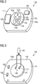
2 zeigt eine Oberseite einer Kernkomponente. -
3 zeigt eine Unterseite der Kernkomponente. -
4 zeigt einen Schaltungsträger. -
5 zeigt eine Querschnittsansicht eines oberen Gehäuseelements. -
6 zeigt eine Querschnittsansicht eines unteren Gehäuseelements. -
7 zeigt einen Kraftfluss in der Sensoranordnung.
-
1 shows a sensor arrangement for measuring pressure and temperature in an exploded view. -
2 shows a top view of a core component. -
3 shows a bottom side of the core component. -
4 shows a circuit carrier. -
5 shows a cross-sectional view of an upper housing element. -
6 shows a cross-sectional view of a lower housing element. -
7 shows a force flow in the sensor arrangement.
Die Sensoranordnung weist eine Kernkomponente 100, ein oberes Gehäuseelement 200 und ein unteres Gehäuseelement 300 auf.The sensor assembly includes a
Die Kernkomponente 100 weist ein Drucksensorelement 104, das dazu ausgestaltet ist, einen Absolut- oder einen Relativdruck eines Fluids, d.h. einer Flüssigkeit oder eines Gases, zu ermitteln. Das Drucksensorelement 104 ist dazu ausgestaltet, einen auf ihn ausgeübten Druck in ein elektrisches Signal umzuwandeln, aus dem die Höhe des Drucks ermittelt werden kann. Eine Medienbeaufschlagung erfolgt auf einer einem Medienanschlusskanal zugewandte Rückseite des Drucksensorelementes 104. Das Drucksensorelement 104 kann eine Biegeplatte aufweisen, deren Fläche und Dicke im Hinblick auf einen gewünschten Messbereich gewählt wird. Bei dem Drucksensorelement 104 handelt es sich um ein piezoresistives Silizium MEMS Element.The
In dem in den Figuren gezeigten Ausführungsbeispielen weist die Kernkomponente 100 zusätzlich ein Temperatursensorelement 105 auf, das dazu ausgestaltet ist, eine Temperatur des Fluids zu ermitteln. In einem alternativen Ausführungsbeispiel weist die Kernkomponente kein Temperatursensorelement 105 auf. Ferner weist die Kernkomponente einen Schaltungsträger 102 auf, über den die Sensorelemente 104, 105 kontaktiert sind.In the embodiments shown in the figures, the
Das Temperatursensorelement 105 ist dazu ausgestaltet, ein elektrisches Signal zu erzeugen, dessen Größe von der Temperatur des Fluids abhängt. Bei dem Temperatursensorelement 105 kann es sich um einen NTC-Thermistor handeln. Das Temperatursensorelement 105 kann in das Messmedium hineinragen, um dessen Temperatur mit möglichst geringer Verfälschung zu erfassen und eine möglichst kurze Ansprechzeit zu gewährleisten.The
Das untere Gehäuseelement 300 bildet einen Medienanschlusskanal, über den das Fluid, dessen Druck und dessen Temperatur gemessen werden sollen, den Sensorelementen 104, 105 der Kernkomponente 100 zugeführt werden kann.The
Das obere Gehäuseelement 200 ist mit dem unteren Gehäuseelement 300 verbunden und umschließt die Kernkomponente 100 und schützt diese auf diese Weise vor Umwelteinflüssen, wobei eine Unterseite der Kernkomponente von dem oberen Gehäuseelement 200 nicht bedeckt wird. Die Sensoranordnung ist derart ausgestaltet, dass von dem Fluid auf die Kernkomponente 100 ausgeübte Kräfte über das obere Gehäuseelement 200 auf das untere Gehäuseelement 300 übertragen werden können.The
Eine axiale Richtung A ist definiert als eine Richtung, die entlang des Medienanschlusskanals verläuft und von einer Unterseite 110 der Kernkomponente 100 zu einer Oberseite 111 der Kernkomponente 100 weist. Als „in axialer Richtung A unten“ werden im Folgenden Elemente bezeichnet, die entgegengesetzt zu der Richtung weisen, aus der das Fluid der Kernkomponente 100 zugeführt wird. Als „in axialer Richtung A oben“ werden im Folgenden Elemente bezeichnet, die in die Richtung weisen, in der das Fluid zu der Kernkomponente 100 geführt wird.An axial direction A is defined as a direction that runs along the media connection channel and points from a
Im Folgenden wird die Kernkomponente 100 beschrieben.
Die Kernkomponente 100 weist das Drucksensorelement 104, das Temperatursensorelement 105, den Schaltungsträger 102, ein Abstützelement 103 und eine Platte 101 auf.The
Eine Oberseite 102a des Schaltungsträgers 102 weist von dem Medienanschlusskanal des unteren Gehäuseelements 300 weg. Eine Unterseite 102b des Schaltungsträgers 102 weist zu dem Medienanschlusskanal des unteren Gehäuseelements 300 hin. A
Auf der Oberseite 102a des Schaltungsträgers 102 sind das Abstützelement 103 und zumindest ein elektronisches Bauteil 106 angeordnet. Der Schaltungsträger 102 weist eine Freistellung 107 auf, in der das Drucksensorelement 104 angeordnet ist. Bei der Freistellung 107 handelt es sich um eine Öffnung, die sich in axialer Richtung A durch den Schaltungsträger erstreckt und die groß genug ist, um das Drucksensorelement 104 aufzunehmen. Das Drucksensorelement 104 ist über Bonddrähte mit dem Schaltungsträger 102 verbunden. Die Bonddrähte überspannen dabei die Freistellung 107.The
Das Abstützelement 103 weist einen Rahmen 103a auf, das das Drucksensorelement 104 und die Freistellung 107 des Schaltungsträgers 102 umschließt. Das Abstützelement 103 weist ferner einen Quersteg 103b auf, der einen von dem Rahmen 103a umschlossenen inneren Bereich in zwei Kammern unterteilt. Das Abstützelement 103 weist zwei in den inneren Bereich hineinragende Nasen 103c auf.The
In einer ersten der beiden Kammern, die von dem Rahmen 103a und dem Quersteg 103b gebildet werden, ist das Drucksensorelement 104 angeordnet. Die Kammer, in der das Drucksensorelement 104 angeordnet ist, kann mit einer Passivierung gefüllt sein, die das Drucksensorelement 104 bedecken kann.The
Das Abstützelement 103 steht in axialer Richtung von dem Schaltungsträger 102 nach oben weg und bildet eine Anschlagsfläche, an der das obere Gehäuseelement 200 anliegt und über die Kräfte auf das obere Gehäuseelement 200 übertragen werden. Eine Oberseite des Rahmens 103a, eine Oberseite des Querstegs 103b und Oberseiten der in den inneren Bereich ragenden Nasen 103c liegen dabei an dem oberen Gehäuseelement 200 an.The
In einer zweiten der beiden Kammern, die von dem Rahmen 103a und dem Quersteg 103b gebildet werden sind, sind elektrische Kontakte 108 des Temperatursensorelementes 105 angeordnet.In a second of the two chambers formed by the
Die auf dem Schaltungsträger 102 angeordneten elektronischen Bauteile 106 bilden eine Ansteuer- und Auswerteelektronik, die mit dem Drucksensorelement 104 und dem Temperatursensorelement 105 verschaltet ist. Der Schaltungsträger 102 weist ein Leiterplattenmaterial auf, beispielsweise FR4.The
Auf der Unterseite 102b des Schaltungsträgers 102 ist die Platte 101 angeordnet, die ein medienbeständiges Material aufweist, beispielsweise Keramik, Stahl, Glas oder einen Kunststoff. Die Platte 101 ist derart angeordnet, dass sie den von dem unteren Gehäuseelement 300 gebildeten Medienanschlusskanal gegen den Schaltungsträger 102 abdichtet. Die Platte 101 weist einen Kanal 109 auf, durch den ein Fluid aus dem Medienanschlusskanal zu dem Drucksensorelement 104 gelangen kann. Auf einer von dem Medienanschlusskanal abgewandten Seite des Kanals 109 ist das Drucksensorelement 104 angeordnet.The
Die Platte 101 weist Durchführungen 112 für Anschlussdrähte des Temperatursensorelementes 105 auf. Sind die Anschlussdrähte in den Durchführungen 112 angeordnet, werden die Durchführungen 112 durch ein Vergussmaterial verschlossen und auf diese Weise abgedichtet. Auf der Unterseite 102b des Schaltungsträgers 102 können weitere elektronische Bauteile 106 angeordnet sein, die Bestandteile der Ansteuer- und Auswerteelektronik sind.The
Der Schaltungsträger 102 ermöglicht eine mechanische und elektrische Anbindung der elektronischen Bauteile 106 und der Sensorelemente 104, 105. Ferner ist der Schaltungsträger 102 mit in dem oberen Gehäuseelement 200 angeordneten Kontaktelementen 202 elektrisch und mechanisch verbunden.The
Das Abstützelement 103 und die Platte 101 können mit dem Schaltungsträger 102 jeweils über einen Klebstoff verbunden sein.The
Der mittlere Bereich 113 umfasst den geometrischen Mittelpunkt des Schaltungsträgers. Der mittlere Bereich 113 umfasst zumindest 10 % der Fläche des Schaltungsträgers 102, vorzugsweise zumindest 25 % der Fläche des Schaltungsträgers 102. Eine äußere Kontur des mittleren Bereichs 113 wird durch den von dem Abstützelement 103 gebildeten Rahmen 103a festgelegt, wobei der äußere Rand des Rahmens 103a eine Grenze zwischen dem mittleren Bereich 113 und dem Randbereich 114 bildet.The
Jeder Abstand AA des Abstützelements 103 von einem Randpunkt P1 des Schaltungsträgers 102 beträgt mindestens 5%, vorzugsweise 10% oder 20%, einer Länge L einer Geraden beträgt, die den Randpunkt P1 mit einem gegenüberliegende Randpunkt P2 des Schaltungsträgers 102 verbindet und durch einen Mittelpunkt MP des Schaltungsträgers 102 verläuft. Die Länge der Geraden gibt einen Durchmesser des Schaltungsträgers 102 an. Die beschriebene Anordnung ermöglicht es, dass das Abstützelement 103 mittig auf dem Schaltungsträger 102 angeordnet ist und von den Rändern des Schaltungsträgers 102 einen hinreichend großen Abstand aufweist.Each distance AA of the
Eine auf die Kernkomponente 100 durch das Fluid ausgeübte Kraft wird über das Abstützelement 103 auf das obere Gehäuseelement 200 weitergeleitet. Durch die Anordnung des Abstützelements 103 im mittleren Bereich 113 des Schaltungsträgers 102 wird sichergestellt, dass die Biegemomente, die von der Kraft auf die Kernkomponente 100 ausgeübt werden, minimiert werden. Die Kraft wird durch das Abstützelement 103 über den mittleren Bereich 113, und somit auch über den Mittelpunkt der Kernkomponente 100, auf das obere Gehäuseelement 200 übertragen. Da der mittlere Bereich 113 zur Kraftübertragung genutzt wird, kann ein Verbiegen der Kernkomponente 100 vermieden werden, zu dem es kommen könnte, wenn die Kraft über den Randbereich 114 übertragen würde.A force exerted on the
Da der mittlere Bereich 113 zumindest 10 %, vorzugsweise 25 %, der Fläche des Schaltungsträgers 102 umfasst und durch den Rahmen 103a festgelegt wird, wird sichergestellt, dass die Kraft über eine ausreichend große Fläche, und nicht etwa annähernd punktförmig, übertragen wird, so dass das Auftreten einer einzelnen Kraftspitze in der Kernkomponente 100 vermieden wird, die sonst zu Messungenauigkeiten und/oder zu einer verringerten Langzeitstabilität führen könnte.Since the
Im Folgenden wird das obere Gehäuseelement 200 beschrieben.
Das obere Gehäuseelement 200 weist ein Kunststoffelement 201 und Kontaktelemente 202 auf. Das Kunststoffelement 201 erstreckt sich im Wesentlichen in axialer Richtung A. In seinem unteren Bereich weist das Kunststoffelement 201 einen Kragen 203 auf, das heißt einen Bereich, der gegenüber den anderen Bereichen des oberen Gehäuseelementes 200 einen größeren Querschnitt aufweist.The
Der Kragen 203 des oberen Gehäuseelementes 200 weist eine Steifigkeit auf, die ausreicht, um eine Kraft in axialer Richtung A auf eine an dem Kragen 203 in axialer Richtung anliegende Bördelung 301 des unteren Gehäuseelements 300 umzuleiten.The
Der Kragen 203 ist dazu ausgestaltet, die Kernkomponente 100 zu umschließen und in axialer Richtung A nach unten über die Kernkomponente 100 hinauszuragen. Im Inneren des Kragens 203 ist eine Anschlagsfläche 204 ausgebildet, an der das Abstützelement 104 der Kernkomponente 100 anliegt. Über die Anschlagsfläche 204 werden Kräfte von dem Abstützelement 104 auf das obere Gehäuseelement 200 übertragen. Das obere Gehäuseelement 200 ist dazu ausgestaltet, diese Kräfte auf die Bördelung 301 des unteren Gehäuseelements 300 abzuleiten.The
Ferner weist das obere Gehäuseelement die Kontaktelemente 202 auf, die elektrisch mit dem Schaltungsträger 102 verbunden sind. Die Kontaktelemente 202 ermöglichen eine elektrische Kontaktierung des Schaltungsträgers 102 mit einer externen Elektronik. Die Kontaktelemente 202 sind als metallische, federnde Kontaktstifte ausgeführt. Sie sind dazu ausgestaltet, in Kontaktanschlüsse des Schaltungsträgers 102 eingesteckt zu werden und auf diese Weise die Kernkomponente 100 bei der Montage zu positionieren.Furthermore, the upper housing element has the
Jeder der Kontaktelemente 202 weist zwei Biegungen auf, wobei die Kontaktelemente 202 in einem in axialer Richtung A oberen Bereich des oberen Gehäuseelementes 200 parallel zueinander in einem geringen Abstand verlaufen und in dem Kragen 203 des oberen Gehäuseelementes 200 weiter voneinander entfernt angeordnet sind. Durch die beiden Biegungen sind die Kontaktelemente 202 gefedert. Das Kunststoffteil 201 weist Führungselemente auf, die den Verlauf der Kontaktelemente 202 festlegen und die eine Freistellung aufweisen, so dass auf diese Weise ein Federn der Kontaktelemente 202 ermöglicht wird. Dadurch können Fertigungstoleranzen ausgeglichen werden.Each of the
An einer Außenfläche 205 des Kragens 203, die an der Bördelung 301 des unteren Gehäuseelements 300 anliegt, wird ferner ein Verguss 206 aufgebracht, über den das obere Gehäuseelement 200 und das untere Gehäuseelement 300 miteinander verbunden und abgedichtet werden. Durch den Verguss 206 wird das Innere des oberen Gehäuseelementes 200 und des unteren Gehäuseelements 300 gegen Umwelteinflüsse abgedichtet. Außerdem sorgt der Verguss 206 für eine mechanische Stabilisierung der Verbindung der Gehäuseelemente 200, 300. Der Verguss 206 kann eine Dichtmasse aufweisen, die Unterschiede in den Ausdehnungskoeffizienten des oberen und des unteren Gehäuseelementes 200, 300 ausgleicht. Auf diese Weise kann das Entstehen von mechanischen Spannungen reduziert oder vermieden werden, so dass eine langzeitstabile Abdichtung der Verbindung der Bördelung mit dem Kragen gewährleistet ist.On an
Das untere Gehäuseelement 300 ist dazu ausgestaltet mit dem oberen Gehäuseelement 200 verbunden zu werden. Das untere Gehäuseelement 300 weist einen im Inneren liegenden ersten Dichtungsring 302 auf und kann ferner einen an der Außenseite des unteren Gehäuseelements liegenden zweiten Dichtungsring 303 aufweisen. Das untere Gehäuseelement kann ferner ein stutzenförmiges Schutzelement 304 aufweisen.The
Das untere Gehäuseelement 300 weist einen oberen Bereich mit einem großen Querschnitt auf, der dazu ausgestaltet ist, die Kernkomponente 100 zu umschließen und den Kragen 203 des oberen Gehäuseelementes 200 ebenfalls zu umschließen. Der obere Bereich weist dabei an seinem oberen Ende die nach innen weisende Bördelung 301 auf. Diese liegt entweder unmittelbar oder über den Verguss 206 an der Außenfläche 205 des Kragens 203 des oberen Gehäuseelementes 200 an.The
Der erste innenliegende Dichtungsring 302 dichtet den Medienanschlusskanal gegen die Platte 101 ab. Der innenliegende Dichtungsring 302 bildet mit dem unteren Gehäuseelement 300 und der Platte 101 eine axiale Dichtung aus.The first
Ein unterer Bereich des unteren Gehäuseelements 300 weist einen im Vergleich zum oberen Bereich kleineren Durchmesser auf. Der untere Bereich ist rohrförmig ausgestaltet und in seinem Inneren hohl. Das Innere des unteren Bereichs bildet den Medienanschlusskanal, über den ein Fluid zu der Kernkomponente 100 geleitet wird. Die Außenwand des unteren Bereichs kann als Gewinde ausgestaltet sein. An der Außenseite des unteren Gehäuseelements 300 kann in dem Übergang vom unteren Bereich zum oberen Bereich der zweite Dichtungsring 303 angeordnet sein. Dieser ist dazu ausgestaltet, beim Verbau der Sensoranordnung das untere Gehäuseelement 300 abzudichten. Alternative Ausgestaltungen des Dichtungsbereichs des unteren Gehäuseelements 300 sind möglich.A lower region of the
Das Schutzelement 304 kann so ausgestaltet sein, dass es das Temperatursensorelement 105 einschießt und auf diese Weise mechanisch schützt. Gleichzeitig muss es einen guten Zugang des Messmediums zum Temperatursensorelement 105 ermöglichen.The
Ferner kann das Schutzelement 304 das Temperatursensorelement 105 gegen das untere Gehäuseelement 300 elektrisch und thermisch isolieren und auf diese Weise die Messgenauigkeit erhöhen.Furthermore, the
Das Schutzelement 304 kann ein Kunststoffteil sein, wobei es mittels eines Formschlusses im unteren Gehäuseelement 300 fixiert sein kann. Da das Schutzelement 304 nicht an der Kernkomponente 100 befestigt ist, wird von dem Schutzelement 304 keine mechanische Belastung auf die Kernkomponente 100 ausgeübt. Ein beidseitiger Formschluss zwischen dem Schutzelement 304 und dem unteren Bereich des unteren Gehäuseelements 300 stellt sicher, dass das Schutzelement 304 im unteren Gehäuseelement 300 gehalten wird. Der Formschluss kann beispielsweise durch eine Umformung, beispielsweise Wärmeverstemmen, gebildet sein. In einem alternativen Ausführungsbeispiel kann die Sensoranordnung kein Schutzelement 304 aufweisen.The
In dem in unteren Gehäuseelement 300 gebildeten Medienanschlusskanal zeigen die Pfeile einen Druck p, der sowohl in radialer als auch in axialer Richtung wird. In der Kernkomponente 100 und im oberen Gehäuseelement 200 zeigen die Pfeile eine Kraft f.In the media connection channel formed in the
Das durch den Medienanschluss geführte Fluid übt mit seinem Druck eine in axialer Richtung A nach oben gerichtete Kraft auf die Kernkomponente 100 aus. Diese Kraft wird zunächst auf die Platte 101 ausgeübt, die den Medienanschlusskanal abdichtet. Über die Platte 101 und den Schaltungsträger 102 wird die Kraft auf das Abstützelement 103 übertragen. Das Abstützelement 103 bildet eine Anschlagsfläche, die an der Anschlagsfläche 204 des oberen Gehäuseelementes 200 anliegt, sodass die Kraft von dem Abstützelement 103 auf das obere Gehäuseelement 200 übertragen wird. Das obere Gehäuseelement 200 ist nunmehr derart ausgestaltet, dass die Kraft auf die Bördelung 301 des unteren Gehäuseelements 300 überträgt, an die der Kragen 203 des oberen Gehäuseelements 200 in axialer Richtung anliegt.The fluid guided through the media connection exerts a force directed upwards in the axial direction A on the
Im Schaltungsträger 102 wirkt die Kraft in dem mittleren Bereich 113. Die Kraft wirkt nicht auf den Randbereich 114 des Schaltungsträgers 102. Da das Abstützelement 103 im mittleren Bereich 113 des Schaltungsträgers 102 angeordnet ist und an der Anschlagsfläche 204 des oberen Gehäuseelements 200 anliegt, nimmt das Abstützelement 103 die Kraft auf und leitet sie an das obere Gehäuseelement 200 weiter. Dadurch wird ein Verbiegen des Schaltungsträgers 102 verhindert. Auf Auflager im Randbereich 114 des Schaltungsträgers 102 kann verzichtet werden. Der Randbereich 114 des Schaltungsträgers 102 kann für die elektronischen Bauelemente genutzt werden.In the
Die Kernkomponente wird im Nutzenverband hergestellt und kalibriert. Auf diese Weise kann das Herstellungsverfahren verbessert werden und insbesondere kostengünstiger werden.The core component is manufactured and calibrated in a panel assembly. In this way, the manufacturing process can be improved and, in particular, made more cost-effective.
Bezugszeichenreference sign
- 100100
- Kernkomponentecore component
- 101101
- Platteplate
- 102102
- Schaltungsträgercircuit carrier
- 102a102a
- Oberseite des Schaltungsträgerstop of the circuit carrier
- 102b102b
- Unterseite des Schaltungsträgersunderside of the circuit carrier
- 103103
- Abstützelementsupport element
- 103a103a
- RahmenFrame
- 103b103b
- Querstegcrossbar
- 103c103c
- NaseNose
- 104104
- Drucksensorelementpressure sensor element
- 105105
- Temperatursensorelementtemperature sensor element
- 106106
- Elektronisches BauteilElectronic component
- 107107
- Freistellungexemption
- 108108
- Elektrischer Kontakt des TemperatursensorelementsElectrical contact of the temperature sensor element
- 109109
- Kanalchannel
- 110110
- Unterseite der Kernkomponentebottom of the core component
- 111111
- Oberseite der Kernkomponentetop of the core component
- 112112
- Durchführungimplementation
- 113113
- mittlerer Bereichmiddle range
- 114114
- Randbereich edge area
- 200200
- oberes Gehäuseelementupper housing element
- 201201
- Kunststoffelementplastic element
- 202202
- Kontaktelementcontact element
- 203203
- Kragencollar
- 204204
- Anschlagsflächestop surface
- 205205
- Außenfläche des Kragensouter surface of the collar
- 206206
- Verguss casting
- 300300
- unteres Gehäuseelementlower housing element
- 301301
- Bördelungflanging
- 302302
- Dichtungsringsealing ring
- 303303
- Dichtungsringsealing ring
- 304304
- Schutzelement protective element
- AA
- axiale Richtungaxial direction
- AAAA
- Abstand Abstützelement zu RandpunktDistance support element to edge point
- P1P1
- Randpunktedge point
- P2P2
- Randpunktedge point
- MPMP
- Mittelpunktcenter
- LL
- Länge der Geraden von P1 zu P2Length of the line from P1 to P2
Claims (16)
Priority Applications (5)
| Application Number | Priority Date | Filing Date | Title |
|---|---|---|---|
| DE102023110113.7A DE102023110113A1 (en) | 2023-04-20 | 2023-04-20 | Sensor arrangement and method for producing a plurality of sensor arrangements |
| CN202480025627.4A CN120936855A (en) | 2023-04-20 | 2024-03-22 | Sensor device and method for producing a plurality of sensor devices |
| JP2025558894A JP2026512085A (en) | 2023-04-20 | 2024-03-22 | Method for manufacturing a sensor device and multiple sensor devices |
| EP24716664.8A EP4698874A1 (en) | 2023-04-20 | 2024-03-22 | Sensor assembly and method for producing a plurality of sensor assemblies |
| PCT/EP2024/057836 WO2024217823A1 (en) | 2023-04-20 | 2024-03-22 | Sensor assembly and method for producing a plurality of sensor assemblies |
Applications Claiming Priority (1)
| Application Number | Priority Date | Filing Date | Title |
|---|---|---|---|
| DE102023110113.7A DE102023110113A1 (en) | 2023-04-20 | 2023-04-20 | Sensor arrangement and method for producing a plurality of sensor arrangements |
Publications (1)
| Publication Number | Publication Date |
|---|---|
| DE102023110113A1 true DE102023110113A1 (en) | 2024-10-24 |
Family
ID=90718746
Family Applications (1)
| Application Number | Title | Priority Date | Filing Date |
|---|---|---|---|
| DE102023110113.7A Pending DE102023110113A1 (en) | 2023-04-20 | 2023-04-20 | Sensor arrangement and method for producing a plurality of sensor arrangements |
Country Status (5)
| Country | Link |
|---|---|
| EP (1) | EP4698874A1 (en) |
| JP (1) | JP2026512085A (en) |
| CN (1) | CN120936855A (en) |
| DE (1) | DE102023110113A1 (en) |
| WO (1) | WO2024217823A1 (en) |
Citations (7)
| Publication number | Priority date | Publication date | Assignee | Title |
|---|---|---|---|---|
| DE10014992A1 (en) * | 2000-03-25 | 2001-10-04 | Bosch Gmbh Robert | Sensor arrangement for high pressure sensor has electric connections provided between hybrid circuit and sensor circuit and earth connection to housing |
| US20060144156A1 (en) * | 2005-01-03 | 2006-07-06 | Borzabadi Hamid R | Integrated pressure sensor and method of manufacture |
| US7216547B1 (en) * | 2006-01-06 | 2007-05-15 | Honeywell International Inc. | Pressure sensor with silicon frit bonded cap |
| US20180306659A1 (en) * | 2017-04-20 | 2018-10-25 | Honeywell International Inc. | Pressure sensor assembly |
| DE102017126121A1 (en) * | 2017-11-08 | 2019-05-09 | Tdk Electronics Ag | Pressure sensor system with protection against freezing medium |
| CN215374270U (en) * | 2021-06-16 | 2021-12-31 | 布瑞特智联科技(杭州)有限公司 | Pressure and temperature integrated sensor for new energy automobile |
| CN218121028U (en) * | 2022-08-04 | 2022-12-23 | 孝感华工高理电子有限公司 | Temperature and pressure sensor |
Family Cites Families (5)
| Publication number | Priority date | Publication date | Assignee | Title |
|---|---|---|---|---|
| US4850227A (en) * | 1987-12-22 | 1989-07-25 | Delco Electronics Corporation | Pressure sensor and method of fabrication thereof |
| US5703296A (en) * | 1995-06-27 | 1997-12-30 | Delco Electronics Corp. | Pressure sensor having reduced hysteresis and enhanced electrical performance at low pressures |
| DE102007054828A1 (en) * | 2007-08-08 | 2009-03-12 | Hahn-Schickard-Gesellschaft für angewandte Forschung e.V. | Sensor element and a method for producing a capacitive sensor |
| KR101740014B1 (en) * | 2015-06-15 | 2017-05-26 | 주식회사 아이티엠반도체 | Pressure sensor device and method of fabricating the same |
| DE102019208013A1 (en) * | 2019-05-31 | 2020-12-03 | Robert Bosch Gmbh | Sensor arrangement for determining a pressure of a fluid medium |
-
2023
- 2023-04-20 DE DE102023110113.7A patent/DE102023110113A1/en active Pending
-
2024
- 2024-03-22 CN CN202480025627.4A patent/CN120936855A/en active Pending
- 2024-03-22 EP EP24716664.8A patent/EP4698874A1/en active Pending
- 2024-03-22 WO PCT/EP2024/057836 patent/WO2024217823A1/en not_active Ceased
- 2024-03-22 JP JP2025558894A patent/JP2026512085A/en not_active Withdrawn
Patent Citations (7)
| Publication number | Priority date | Publication date | Assignee | Title |
|---|---|---|---|---|
| DE10014992A1 (en) * | 2000-03-25 | 2001-10-04 | Bosch Gmbh Robert | Sensor arrangement for high pressure sensor has electric connections provided between hybrid circuit and sensor circuit and earth connection to housing |
| US20060144156A1 (en) * | 2005-01-03 | 2006-07-06 | Borzabadi Hamid R | Integrated pressure sensor and method of manufacture |
| US7216547B1 (en) * | 2006-01-06 | 2007-05-15 | Honeywell International Inc. | Pressure sensor with silicon frit bonded cap |
| US20180306659A1 (en) * | 2017-04-20 | 2018-10-25 | Honeywell International Inc. | Pressure sensor assembly |
| DE102017126121A1 (en) * | 2017-11-08 | 2019-05-09 | Tdk Electronics Ag | Pressure sensor system with protection against freezing medium |
| CN215374270U (en) * | 2021-06-16 | 2021-12-31 | 布瑞特智联科技(杭州)有限公司 | Pressure and temperature integrated sensor for new energy automobile |
| CN218121028U (en) * | 2022-08-04 | 2022-12-23 | 孝感华工高理电子有限公司 | Temperature and pressure sensor |
Also Published As
| Publication number | Publication date |
|---|---|
| WO2024217823A1 (en) | 2024-10-24 |
| JP2026512085A (en) | 2026-04-14 |
| EP4698874A1 (en) | 2026-02-25 |
| CN120936855A (en) | 2025-11-11 |
Similar Documents
| Publication | Publication Date | Title |
|---|---|---|
| DE60031869T2 (en) | CAPACITIVE DRUCKWANDLER | |
| EP1269135B1 (en) | Pressure sensor module | |
| DE10196145B3 (en) | Pressure transducer with improved isolator system | |
| DE112004000818B4 (en) | Pressure sensors capsule | |
| DE102007029356B4 (en) | Differential pressure sensor with symmetrically provided sensor chips and pressure introduction channels | |
| EP1182432B1 (en) | Flow sensor with housing | |
| DE102007042439B4 (en) | pressure sensor | |
| DE10311977B4 (en) | Pressure transducer with process coupling | |
| DE102004041388A1 (en) | Pressure sensor cell for hydraulic actuators and cars has pressure sensor chip on thin film coated glass base in resin housing with output signal connections | |
| EP0759547A1 (en) | Pressure sensor | |
| DE2709834A1 (en) | CAPACITIVE PRESSURE SENSOR | |
| DE2117271C2 (en) | Acceleration-compensated capacitive pressure transducer | |
| DE10130375B4 (en) | Differential Pressure Sensor | |
| WO2013160019A2 (en) | Pressure sensor | |
| EP1611422B1 (en) | Relative pressure transducer | |
| WO2008025182A2 (en) | Sensor unit | |
| AT504485B1 (en) | PIEZOELECTRIC PRESSURE SENSOR | |
| DE102014119407A1 (en) | Differential pressure sensor and differential pressure transducer with such a differential pressure sensor | |
| DE102012102020A1 (en) | Micromechanical measuring element | |
| DE10393943B3 (en) | Differential Pressure Sensor | |
| WO2006061035A1 (en) | Differential pressure transducer unit | |
| DE102023110113A1 (en) | Sensor arrangement and method for producing a plurality of sensor arrangements | |
| DE102016124024A1 (en) | Pressure sensor for determining a differential pressure | |
| DE10130376B4 (en) | Differential Pressure Sensor | |
| DE102007015476A1 (en) | Pressure transfer medium comprising mixture of liquid and solid, e.g. oil and ceramic particles, useful in pressure sensors for providing reliable results at varying temperatures |
Legal Events
| Date | Code | Title | Description |
|---|---|---|---|
| R012 | Request for examination validly filed | ||
| R016 | Response to examination communication |