DE102020118370B3 - Device and method for converting thermal energy into electrical energy - Google Patents
Device and method for converting thermal energy into electrical energy Download PDFInfo
- Publication number
- DE102020118370B3 DE102020118370B3 DE102020118370.4A DE102020118370A DE102020118370B3 DE 102020118370 B3 DE102020118370 B3 DE 102020118370B3 DE 102020118370 A DE102020118370 A DE 102020118370A DE 102020118370 B3 DE102020118370 B3 DE 102020118370B3
- Authority
- DE
- Germany
- Prior art keywords
- thermomagnetic
- magnetic flux
- components
- component
- magnetic
- Prior art date
- Legal status (The legal status is an assumption and is not a legal conclusion. Google has not performed a legal analysis and makes no representation as to the accuracy of the status listed.)
- Active
Links
Images

Classifications
-
- H—ELECTRICITY
- H02—GENERATION; CONVERSION OR DISTRIBUTION OF ELECTRIC POWER
- H02N—ELECTRIC MACHINES NOT OTHERWISE PROVIDED FOR
- H02N11/00—Generators or motors not provided for elsewhere; Alleged perpetua mobilia obtained by electric or magnetic means
- H02N11/002—Generators
-
- H—ELECTRICITY
- H10—SEMICONDUCTOR DEVICES; ELECTRIC SOLID-STATE DEVICES NOT OTHERWISE PROVIDED FOR
- H10N—ELECTRIC SOLID-STATE DEVICES NOT OTHERWISE PROVIDED FOR
- H10N15/00—Thermoelectric devices without a junction of dissimilar materials; Thermomagnetic devices, e.g. using the Nernst-Ettingshausen effect
- H10N15/20—Thermomagnetic devices using thermal change of the magnetic permeability, e.g. working above and below the Curie point
Landscapes
- General Induction Heating (AREA)
Abstract
Die Erfindung bezieht sich auf das Gebiet der Energietechnik und betrifft eine Vorrichtung und ein Verfahren zur Umwandlung von thermischer Energie in elektrische Energie. Nachteilig bei den bekannten Lösungen ist, dass thermomagnetische Generatoren zu hohe thermische Verluste, einen geringen Systemwirkungsgrad und einen zu langsamen Wärmeaustausch aufweisen.Mit der erfindungsgemäßen Lösung wird ein thermomagnetischer Generator bereitgestellt, der zwei im Wesentlichen baugleiche Baugruppen enthält, wobei jede Baugruppe mindestens ein Bauelement aus magnetflussleitendem Material, mindestens eine Spule und mindestens ein Bauelement aus hartmagnetischem Material aufweist, und bei dem die beiden Baugruppen zwei Magnetkreise bilden. Zudem weist jede Baugruppe mindestens zwei Einlasskanäle auf, die direkt im Bauelement aus magnetflussleitendem Material ausgebildet sind Die Vorrichtung kann beispielsweise in der Automobilindustrie, in der Lebensmittelindustrie, in der chemischen Industrie oder an Großrechnern zur Umwandlung von Abwärme in elektrische Energie, aber auch zur Umwandlung von Wärme aus der Umwelt in elektrische Energie eingesetzt werden.The invention relates to the field of energy technology and relates to a device and a method for converting thermal energy into electrical energy. The disadvantage of the known solutions is that thermomagnetic generators have too high thermal losses, a low system efficiency and too slow heat exchange. With the solution according to the invention, a thermomagnetic generator is provided which contains two essentially structurally identical assemblies, each assembly consisting of at least one component Has magnetic flux-conducting material, at least one coil and at least one component made of hard magnetic material, and in which the two assemblies form two magnetic circuits. In addition, each assembly has at least two inlet channels, which are formed directly in the component made of magnetic flux-conducting material Heat from the environment can be used in electrical energy.
Description
Die Erfindung bezieht sich auf das Gebiet der Energietechnik und betrifft eine Vorrichtung und ein Verfahren zur Umwandlung von thermischer Energie in elektrische Energie. Die erfindungsgemäße Vorrichtung betrifft einen thermomagnetischen Generator, der beispielsweise in der Automobilindustrie, in der Lebensmittelindustrie, in der chemischen Industrie oder an Großrechnern zur Umwandlung von Abwärme in elektrische Energie, aber auch zur Umwandlung von Wärme aus der Umwelt (Geothermie) in elektrische Energie eingesetzt werden kann.The invention relates to the field of energy technology and relates to a device and a method for converting thermal energy into electrical energy. The device according to the invention relates to a thermomagnetic generator which is used, for example, in the automotive industry, in the food industry, in the chemical industry or on mainframes to convert waste heat into electrical energy, but also to convert heat from the environment (geothermal energy) into electrical energy can.
Das Prinzip des thermomagnetischen Generators ist bereits seit dem 19. Jahrhundert bekannt. Die theoretisch fundierte Wirkungsweise eines thermomagnetischen Generators wurde insbesondere durch die Erkenntnisse von Brillouin und Iskenderian aufgezeigt [
Der besondere Vorteil thermomagnetischer Generatoren besteht darin, dass thermische Energie direkt in elektrische Energie umgewandelt wird, indem eine magnetische Phasenumwandlung eines thermomagnetischen Materials ausgenutzt wird, wodurch keine Zwischenumwandlung in mechanische Energie erforderlich ist. Für thermomagnetische Motoren [
In neuer Zeit werden als thermomagnetisches Material für thermomagnetische Generatoren auch Materialen eingesetzt, die einen magnetokalorischen Effekt (MCE) zeigen. In einem Material, das einen magnetokalorischen Effekt zeigt, führt die Ausrichtung von zufällig orientierten magnetischen Momenten durch ein externes Magnetfeld zu einer verstärkten Erwärmung des thermomagnetischen Materials. Diese Wärme kann vom MCE-Material in die Umgebungsatmosphäre durch einen Wärmetransfer abgeführt werden. Wenn das Magnetfeld daraufhin abgestellt oder entfernt wird, gehen die magnetischen Momente wieder in eine Zufallsanordnung über, was zu einem Abkühlen des Materials unter Umgebungstemperatur führt. Dieser Effekt kann einerseits zu Kühlzwecken ausgenutzt werden, andererseits, um Wärme in elektrische Energie umzuwandeln.Recently, materials that show a magnetocaloric effect (MCE) have also been used as thermomagnetic materials for thermomagnetic generators. In a material that shows a magnetocaloric effect, the alignment of randomly oriented magnetic moments by an external magnetic field leads to increased heating of the thermomagnetic material. This heat can be dissipated from the MCE material into the surrounding atmosphere by means of heat transfer. If the magnetic field is then switched off or removed, the magnetic moments go back into a random arrangement, which leads to a cooling of the material below ambient temperature. This effect can be used for cooling purposes on the one hand, and to convert heat into electrical energy on the other.
Der besondere Vorteil von thermomagnetischen Materialien mit ausgeprägtem MCE besteht insbesondere darin, dass sich deren Magnetisierung in einem relativ kleinen Temperaturbereich stark ändert und dass die Curie-Temperatur dieser Materialien im Bereich natürlicher Umgebungstemperaturen liegt. Damit sind thermomagnetische Generatoren besonders bei geringen Temperaturunterschieden im Bereich unterhalb von 100°C effektiv einsetzbar. Für den Einsatz in thermomagnetischen Generatoren empfehlen sich beispielsweise folgende Materialien: LaFe11.8Si1.2H1, Ni45Co5Mn36.7In13.3, Mn1.25Fe0.7P0.5Si0.5, Y2Fe17 sowie Gadolinium [Dzekan, D. et al., Efficient and affordable thermomagnetic materials for harvesting low grade waste heat, arxiv/2001.03375 (2020)]. Ebenfalls einsetzbar ist das Material La(FeCoSi)13, das kommerziell unter dem Handelsnamen CaloriVAC C (Firma Vacuumschmelze Hanau) erhältlich ist.The particular advantage of thermomagnetic materials with a pronounced MCE is in particular that their magnetization changes significantly in a relatively small temperature range and that the Curie temperature of these materials is in the range of natural ambient temperatures. This means that thermomagnetic generators can be used effectively, particularly with small temperature differences in the range below 100 ° C. For example, the following materials are recommended for use in thermomagnetic generators: LaFe 11.8 Si 1.2 H 1 , Ni 45 Co 5 Mn 36.7 In 13.3 , Mn 1.25 Fe 0.7 P 0.5 Si 0.5 , Y 2 Fe 17 and gadolinium [Dzekan, D. et al ., Efficient and affordable thermomagnetic materials for harvesting low grade waste heat, arxiv / 2001.03375 (2020)]. The material La (FeCoSi) 13 , which is commercially available under the trade name CaloriVAC C (Vacuumschmelze Hanau), can also be used.
Trotz dieses signifikanten Fortschrittes erreichen bisher bekannte thermomagnetische Generatoren lediglich einen thermodynamischen Wirkungsgrad von ηrel = 1.7*10-3 %, relativ zum Carnot-Wirkungsgrad ηCarnot=ΔT/Thot, der das thermodynamische Limit darstellt. [Waske, A. et al. Energy harvesting near room temperature using a thermomagnetic generator with a pretzel-like magnetic flux topology. Nat. Energy 4(68-74) (2019).]Despite this significant progress, known thermomagnetic generators only achieve a thermodynamic efficiency of η rel = 1.7 * 10 -3 %, relative to the Carnot efficiency η Carnot = ΔT / T hot , which represents the thermodynamic limit. [Waske, A. et al. Energy harvesting near room temperature using a thermomagnetic generator with a pretzel-like magnetic flux topology. Nat. Energy 4 (68-74) (2019).]
Zur Umwandlung von thermischer Energie in elektrische Energie sind aus dem Stand der Technik verschiedene Lösungen bekannt.Various solutions are known from the prior art for converting thermal energy into electrical energy.
Bekannt ist aus der
Aus der
Aus der
Die
Aus der
Aus der
Aus der
Aus der
Aus der
Auch bekannt aus der
Zudem sind aus der
Nachteilig bei den aus dem Stand der Technik bekannten Lösungen ist, dass bisherige thermomagnetische Generatoren, insbesondere auch im Vergleich zu thermoelektrischen Generatoren, zu hohe thermische Verluste, einen zu geringen Systemwirkungsgrad und einen zu langsamen Wärmeaustausch aufweisen. Zudem können die bekannten thermomagnetischen Generatoren nicht flexibel an sich ändernde Einsatzbedingungen angepasst werden.A disadvantage of the solutions known from the prior art is that previous thermomagnetic generators, in particular also in comparison to thermoelectric generators, have too high thermal losses, too low a system efficiency and too slow a heat exchange. In addition, the known thermomagnetic generators cannot be flexibly adapted to changing conditions of use.
Aufgabe der Erfindung ist es, einen thermomagnetischen Generator bereitzustellen, der gegenüber den Lösungen des Standes der Technik geringere thermische Verluste, einen verbesserten Systemwirkungsgrad und einen schnelleren Wärmeaustausch aufweist. Zudem besteht die Aufgabe der Erfindung darin, einen thermomagnetischen Generator bereit zu stellen, der mit geringem Aufwand flexibel an sich ändernde Einsatzbedingungen angepasst werden kann.The object of the invention is to provide a thermomagnetic generator which, compared to the solutions of the prior art, has lower thermal losses, an improved system efficiency and a faster heat exchange. In addition, the object of the invention is to provide a thermomagnetic generator which can be flexibly adapted to changing conditions of use with little effort.
Die Aufgabe wird durch die in den Ansprüchen angegebene Erfindung gelöst. Vorteilhafte Ausgestaltungen sind Gegenstand der Unteransprüche, wobei die Erfindung auch Kombinationen der einzelnen abhängigen Ansprüche im Sinne einer und-Verknüpfung einschließt, solange sie sich nicht gegenseitig ausschließen.The object is achieved by the invention specified in the claims. Advantageous refinements are the subject matter of the subclaims, the invention also including combinations of the individual dependent claims in the sense of an and link, as long as they are not mutually exclusive.
Die erfindungsgemäße Aufgabe wird mit einer Vorrichtung zur Umwandlung thermischer Energie in elektrische Energie gelöst, umfassend mindestens einen thermomagnetischen Generator, wobei der thermomagnetische Generator mindestens eine Baugruppe aufweist, die aus einem ersten und einem zweiten Bauteil gebildet ist, wobei das erste und zweite Bauteil jeweils mindestens ein Bauelement aus magnetflussleitendem Material, mindestens eine Spule und mindestens ein Bauelement aus hartmagnetischem Material aufweist und, wobei jedes erste und zweite Bauteil mindestens zwei Einlasskanäle für die Zuführung von Fluiden aufweist, und wobei die mindestens eine Spule eines jeden Bauteils in einem stegartig ausgebildeten Abschnitt des mindestens einen Bauelementes aus magnetflussleitendem Material angeordnet ist, und wobei das erste und zweite Bauteil durch mindestens zwei Verbindungselemente miteinander verbunden sind, die jeweils ein thermomagnetisches Material aufweisen, wodurch mindestens zwei Magnetkreisläufe ausgebildet sind, und wobei die Verbindungselemente jeweils getrennte Öffnungen für die Zu- und Abführung von Fluiden aufweisen, durch die ein wechselseitiges Durchströmen von unterschiedlich temperierten Fluiden durch die mindestens zwei Verbindungselemente und deren thermomagnetisches Material realisierbar ist, wobei das erste und zweite Bauteil baugleich sind, bis auf eine entgegengesetzt ausgerichtete Magnetisierung des mindestens einen Bauelementes aus hartmagnetischem Material des ersten Bauteils gegenüber der Magnetisierung des mindestens einen Bauelementes aus hartmagnetischem Material des zweiten Bauteils.The object of the invention is achieved with a device for converting thermal energy into electrical energy, comprising at least one thermomagnetic generator, the thermomagnetic generator having at least one assembly which is formed from a first and a second component, the first and second component each at least a component made of magnetic flux-conducting material, at least one coil and at least one component made of hard magnetic material and, wherein each first and second component has at least two inlet channels for the supply of fluids, and wherein the at least one coil of each component is in a web-like section of the at least one component made of magnetic flux-conducting material is arranged, and wherein the first and second components are connected to one another by at least two connecting elements, each having a thermomagnetic material, whereby at least two Magnetk rice courses are formed, and wherein the connecting elements each have separate openings for the supply and discharge of fluids through which a reciprocal flow of fluids at different temperatures through the at least two connecting elements and their thermomagnetic material can be realized, the first and second components being structurally identical, except for an oppositely oriented magnetization of the at least one component made of hard magnetic material of the first component compared to the magnetization of the at least one component made of hard magnetic material Material of the second component.
Vorteilhafterweise weisen das erste und zweite Bauteil jeweils zwei Bauelemente aus hartmagnetischem Material auf und sich das erste und zweite Bauelement spiegelbildlich gegenüberliegen.Advantageously, the first and second components each have two components made of hard magnetic material and the first and second components are mirror images of one another.
In einer vorteilhaften Ausgestaltung ist das Verbindungselement mit dem thermomagnetischen Material im Wesentlichen aus parallel und beabstandet angeordneten Rundstäben, Halbrundstäben, Quadrat- oder Rechteckstäben, mittels Powder-In-Tube-Technologie hergestellten magnetokalorischen Drähten und/oder mittels additivem Verfahren hergestellten Formkörpern gebildet.In an advantageous embodiment, the connecting element with the thermomagnetic material is essentially formed from round bars, semicircular bars, square or rectangular bars, magnetocaloric wires produced by means of powder-in-tube technology and / or molded bodies produced by means of an additive process.
Auch vorteilhafterweise weisen die Rundstäbe, Halbrundstäbe Quadrat- oder Rechteckstäbe, magnetokalorischen Drähte und/oder Formkörper eine Höhe oder einen Durchmesser von 0,1 mm bis 0,5 mm auf, wobei besonders vorteilhaft ist, wenn die Rundstäbe, Halbrundstäbe Quadrat- oder Rechteckstäbe, magnetokalorischen Drähte und/oder Formkörper ein Verhältnis Breite zu Höhe von 0,2 bis 1 aufweisen, und auch, wenn das thermomagnetische Material der Verbindungselemente eine Korrosionsschutzschicht aufweist.The round bars, semicircular bars, square or rectangular bars, magnetocaloric wires and / or shaped bodies also advantageously have a height or a diameter of 0.1 mm to 0.5 mm, it being particularly advantageous if the round bars, semicircular bars, square or rectangular bars, magnetocaloric wires and / or shaped bodies have a width to height ratio of 0.2 to 1, and also when the thermomagnetic material of the connecting elements has a corrosion protection layer.
Auch vorteilhaft ist es, wenn sich zwischen den Verbindungselementen aus thermomagnetischem Material und den magnetflussleitenden Materialien mindestens ein thermisch isolierendes Material befindet, das mit dem thermomagnetischen Material des Verbindungselementes und den Bauelementen aus magnetflussleitendem Material kraft-, form- und oder stoffschlüssig verbunden ist und das mindestens eine Öffnung aufweist, durch die der Zufluss von Fluid aus einem Einlasskanal zum thermomagnetischen Material möglich ist, wobei besonders vorteilhafterweise das thermisch isolierende Material eine relative Permeabilität größer als 1000 oder ferromagnetische Ordnung aufweist, und auch vorteilhafterweise, wenn das thermisch isolierende Material auf beiden Seiten des thermomagnetischen Materials der Verbindungselemente in Form von thermischen Isolationsschichten, Folien oder Platten angeordnet ist.It is also advantageous if there is at least one thermally insulating material between the connecting elements made of thermomagnetic material and the magnetic flux-conducting materials, which is non-positively, positively and or cohesively connected to the thermomagnetic material of the connecting element and the components made of magnetic flux-conducting material and which is at least has an opening through which the inflow of fluid from an inlet channel to the thermomagnetic material is possible, the thermally insulating material particularly advantageously having a relative permeability greater than 1000 or ferromagnetic order, and also advantageously if the thermally insulating material on both sides of the thermomagnetic material of the connecting elements is arranged in the form of thermal insulation layers, foils or plates.
Ebenso ist es vorteilhaft, wenn das thermomagnetische Material aus Ferrit oder eine Aerogelschicht ist.It is also advantageous if the thermomagnetic material is made of ferrite or an airgel layer.
In einer vorteilhaften Ausgestaltung der Vorrichtung ist das Bauelement aus magnetflussleitendem Material aus einer niedrigkoerzitiven Permalloy-Legierung, einer hochremanenten FeCo-Legierung oder aus FeSi-Transformatorblechen hergestellt.In an advantageous embodiment of the device, the component is made of magnetic flux-conducting material from a low-coercivity permalloy alloy, a highly retentive FeCo alloy or from FeSi transformer sheets.
Weiterhin ist vorteilhaft, wenn mindestens die Verbindungselemente aus thermomagnetischem Material, die das erste und zweite Bauteil miteinander verbinden, als Module austauschbar sind.It is also advantageous if at least the connecting elements made of thermomagnetic material, which connect the first and second components to one another, can be exchanged as modules.
Und auch vorteilhafterweise sind das erste und zweite Bauteil thermisch voneinander isoliert sind.And the first and second components are also advantageously thermally insulated from one another.
Die erfindungsgemäße Aufgabe wird auch durch ein Verfahren zur Umwandlung thermischer Energie in elektrische Energie mittels der erfindungsgemäßen Vorrichtung gelöst, bei dem über einen ersten von zwei Einlasskanälen, die in einem ersten Bauelement aus magnetflussleitendem Material ausgebildet sind, ein erstes Fluid mit einer Temperatur ϑ1 zugeführt wird und bei dem über einen zweiten von zwei Einlasskanälen, die in einem zweiten Bauelement aus magnetflussleitendem Material ausgebildet sind, ein zweites Fluid mit einer Temperatur ϑ2 zugeführt wird und beide Fluide zu jeweils einem Verbindungselement mit einem thermomagnetischen Material geleitet werden, wodurch das thermomagnetische Material eines ersten Verbindungselementes erwärmt und gleichzeitig das thermomagnetische Material eines zweiten Verbindungselementes abgekühlt wird und die Magnetisierung im thermomagnetischen Material der Verbindungselemente verändert wird und gleichzeitig in einem ersten Magnetkreislauf durch Bauelemente aus hartmagnetischem Material ein gerichteter magnetischer Fluss realisiert wird, der in mindestens einer Spule, die in einem stegartig ausgebildeten Anschnitt der Bauelementen aus magnetflussleitendem Material angeordnet ist, durch die erzeugte magnetische Flussänderung in den Bauelementen aus magnetflussleitendem Material eine elektrische Spannung induziert, und anschließend über den zweiten von zwei Einlasskanälen, die in einem ersten Bauelement aus magnetflussleitendem Material ausgebildet sind, ein erstes Fluid mit einer Temperatur ϑ1 zugeführt wird und bei dem über einen ersten von zwei Einlasskanälen, die in einem zweiten Bauelement aus magnetflussleitendem Material ausgebildet sind, ein zweites Fluid mit einer Temperatur ϑ2 zugeführt wird und beide Fluide zu jeweils einem Verbindungselement mit einem thermomagnetischen Material geleitet werden, wodurch das thermomagnetische Material des gleichen ersten Verbindungselementes nunmehr gekühlt und gleichzeitig das thermomagnetische Material des gleichen zweiten Verbindungselementes nunmehr erwärmt wird und dabei die Magnetisierung im thermomagnetischen Material der Verbindungselemente verändert wird und gleichzeitig in einem zweiten Magnetkreislauf durch die Bauelemente aus hartmagnetischem Material ein gerichteter magnetischer Fluss realisiert wird, der die mindestens eine Spule nunmehr in entgegengesetzter Richtung durchläuft und dabei aufgrund seiner Änderung in derselben mindestens einen Spule eine Spannung mit entgegengesetztem Vorzeichen induziert.The object according to the invention is also achieved by a method for converting thermal energy into electrical energy by means of the device according to the invention, in which a first fluid with a temperature ϑ 1 is supplied via a first of two inlet channels formed in a first component made of magnetic flux-conducting material is and in which a second fluid with a temperature ϑ 2 is supplied via a second of two inlet channels, which are formed in a second component made of magnetic flux-conducting material, and both fluids are each conducted to a connecting element with a thermomagnetic material, whereby the thermomagnetic material a first connecting element is heated and at the same time the thermomagnetic material of a second connecting element is cooled and the magnetization in the thermomagnetic material of the connecting elements is changed and at the same time in a first magnetic circuit through components te a directed magnetic flux is realized from hard magnetic material, which induces an electrical voltage in at least one coil, which is arranged in a web-like section of the components made of magnetic flux-conducting material, through the magnetic flux change generated in the components made of magnetic flux-conducting material, and then over the second of two inlet channels, which are formed in a first component made of magnetic flux-conducting material, a first fluid with a temperature ϑ 1 is supplied and in which a second is supplied via a first of two inlet channels, which are formed in a second component made of magnetic flux-conducting material Fluid with a temperature ϑ 2 is supplied and both fluids are each passed to a connecting element with a thermomagnetic material, whereby the thermomagnetic material of the same first connecting element is now cooled and at the same time the thermomagneti cal material of the same second connecting element is now heated and the magnetization in the thermomagnetic material of the connecting elements is changed and at the same time in a second magnetic circuit the components made of hard magnetic material, a directed magnetic flux is realized, which now runs through the at least one coil in the opposite direction and induces a voltage with the opposite sign due to its change in the same at least one coil.
Mit der erfindungsgemäßen Lösung wird erstmals ein thermomagnetischer Generator bereitgestellt, der gegenüber den Lösungen des Standes der Technik geringere thermische Verluste, einen verbesserten Systemwirkungsgrad, einen schnelleren Wärmeaustausch und somit eine höhere Leistungsdichte ermöglicht. Zudem ist der thermomagnetische Generator in einfacher Weise mit geringem Aufwand flexibel an sich ändernde Einsatzbedingungen anpassbar.With the solution according to the invention, a thermomagnetic generator is provided for the first time which, compared to the solutions of the prior art, enables lower thermal losses, improved system efficiency, faster heat exchange and thus a higher power density. In addition, the thermomagnetic generator can be easily and flexibly adapted to changing conditions of use with little effort.
Erreicht werden die technischen Vorteile und Wirkungen durch einen neuartigen thermomagnetischen Generator, der zwei im Wesentlichen baugleiche Bauteile enthält, wobei jede Baugruppe aus einem ersten und einem zweiten Bauteil gebildet ist, wobei das erste und das zweite Bauteil jeweils mindestens ein Bauelement aus magnetflussleitendem Material, mindestens eine Spule und mindestens ein Bauelement aus hartmagnetischem Material aufweist, und bei dem die beiden Bauteile als Baugruppe zwei Magnetkreise bilden.The technical advantages and effects are achieved by a new type of thermomagnetic generator that contains two essentially structurally identical components, each assembly being formed from a first and a second component, the first and the second component each having at least one component made of magnetic flux-conducting material, at least has a coil and at least one component made of hard magnetic material, and in which the two components form two magnetic circuits as an assembly.
Zudem weist erfindungsgemäß jedes Bauteilmindestens zwei Einlasskanäle auf, die direkt im Bauelement aus magnetflussleitendem Material ausgebildet sind und die wechselseitige Zuführung unterschiedlich temperierter Fluide zu den erfindungsgemäßen Verbindungselementen aus thermomagnetischem Material ermöglichen. Der technische Vorteil der Anordnung von mindestens zwei Einlasskanälen in jedem ersten und zweiten Bauteil aus magnetflussleitendem Material besteht darin, dass die erfindungsgemäßen Einlasskanäle konkret in das Bauelement aus magnetflussleitendem Material (Magnetjoch) eingebracht sind und so das warme Fluid bzw. das kalte Fluid in den thermomagnetischen Generator eingeleitet und direkt dem thermomagnetischen Material der Verbindungselemente zugeführt werden kann. Zudem bietet dies die Möglichkeit, eines der Magnetjoche nur mit warmem (Warmjoch) und das andere Magnetjoch nur mit kaltem Fluid (Kaltjoch) anzusteuern, wodurch thermische Verluste reduziert werden. Durch diesen Aufbau unterscheiden sich die Temperaturen beider Magnetjoche voneinander, die hierfür erforderliche Wärme wird jedoch nur beim Hochfahren der Anlage benötigt und nicht während des Betriebes, so dass hierdurch keine Wärmeverluste entstehen. Dabei ist es auch möglich, dass entweder das warme Fluid oder aber das kalte Fluid auf dem Niveau der Umgebungstemperatur liegt.In addition, according to the invention, each component has at least two inlet channels, which are formed directly in the component from magnetic flux-conducting material and enable the alternating supply of fluids at different temperatures to the connecting elements according to the invention made of thermomagnetic material. The technical advantage of the arrangement of at least two inlet channels in each first and second component made of magnetic flux-conducting material is that the inlet channels according to the invention are specifically introduced into the component made of magnetic flux-conducting material (magnetic yoke) and so the warm fluid or the cold fluid in the thermomagnetic Initiated generator and can be fed directly to the thermomagnetic material of the connecting elements. In addition, this offers the possibility of controlling one of the magnet yokes only with warm fluid (warm yoke) and the other magnet yoke only with cold fluid (cold yoke), whereby thermal losses are reduced. Due to this structure, the temperatures of the two magnet yokes differ from one another, but the heat required for this is only required when the system is started up and not during operation, so that this does not result in any heat losses. It is also possible that either the warm fluid or the cold fluid is at the level of the ambient temperature.
Im Gegensatz zum Stand der Technik, bei dem eine Mischkammer für die Zuführung der Fluide verwendet wird, um dem thermomagnetischen Plattenmaterial alternierend kalte und warme Kühlflüssigkeit zuzuführen, kann durch die erfindungsgemäßen Einlasskanäle im Bauelement aus magnetflussleitendem Material auf eine Mischkammer verzichten werden, wodurch die Durchmischung des warmen und kalten Fluids vermieden wird. Dies führt zu einer Reduzierung der thermischen Verluste und damit zu einer Erhöhung des Systemwirkungsgrades des thermomagnetischen Generators.In contrast to the prior art, in which a mixing chamber is used to supply the fluids in order to alternately supply cold and warm cooling liquid to the thermomagnetic plate material, the inlet channels according to the invention in the component made of magnetic flux-conducting material make it possible to dispense with a mixing chamber, whereby the mixing of the hot and cold fluids are avoided. This leads to a reduction in thermal losses and thus to an increase in the system efficiency of the thermomagnetic generator.
Erfindungsgemäß wird vorgeschlagen, die im Wesentlichen baugleichen Bauteile durch mindestens zwei Verbindungselemente, die jeweils ein thermomagnetisches Material aufweisen, zu mindestens zwei Magnetkreisläufen zu verbinden.According to the invention, it is proposed that the essentially structurally identical components be connected to at least two magnetic circuits by at least two connecting elements, each of which has a thermomagnetic material.
Als Verbindungselement mit einem thermomagnetischen Material soll im Rahmen der Erfindung ein Bauelement verstanden werden, bei dem durch eine Änderung der Temperatur des thermomagnetischen Materials eine Änderung der Magnetisierung realisiert wird. Dabei ist es vorteilhaft, wenn durch das thermomagnetische Material eine Änderung der Magnetisierung > 50 % (bezogen auf den ferromagnetischen Zustand) bei einem Temperaturgradienten unterhalb von ca. 30 Kelvin erreicht wird.A connecting element with a thermomagnetic material is to be understood in the context of the invention as a component in which a change in the magnetization is implemented by changing the temperature of the thermomagnetic material. It is advantageous if the thermomagnetic material changes the magnetization> 50% (based on the ferromagnetic state) at a temperature gradient below approx. 30 Kelvin.
Über die Verbindungselemente mit einem thermomagnetischen Material wird die Verbindung der im Wesentlichen baugleichen Bauteile miteinander hergestellt. Die Verbindungselemente mit dem thermomagnetischen Material weisen Öffnungen für die Zu- und Abführung von Fluiden auf, durch die eine wechselseitige Durchströmung unterschiedlich temperierter Fluide realisierbar ist. Die alternierende Zuführung der Fluide erfolgt somit direkt über die erfindungsgemäßen Einlasskanäle im jeweiligen Bauelement aus magnetflussleitendem Material zu den Verbindungselementen, die ein thermomagnetisches Material aufweisen. Die Fluide durchströmen die Verbindungselemente, somit auch das thermomagnetische Material und verlassen anschließend die Verbindungselemente vorteilhafterweise über seitlich ausgebildete Öffnungen, wobei durch die zentrale Lage der Zuführung und die seitliche Abführung der Fluide nach vorn und hinten eine Halbierung der Aufwärm- bzw. Abkühldauer des thermomagnetischen Materials und damit der Zyklusdauer erreicht wird.The connection of the essentially structurally identical components to one another is established via the connecting elements with a thermomagnetic material. The connecting elements with the thermomagnetic material have openings for the supply and discharge of fluids, through which a reciprocal flow of fluids at different temperatures can be realized. The alternating supply of the fluids thus takes place directly via the inlet channels according to the invention in the respective component made of magnetic flux-conducting material to the connecting elements which have a thermomagnetic material. The fluids flow through the connecting elements, thus also the thermomagnetic material and then leave the connecting elements advantageously via laterally formed openings, the central position of the feed and the lateral discharge of the fluids to the front and back halving the heating or cooling time of the thermomagnetic material and thus the cycle time is reached.
Durch das alternierende Zuführen der Fluide wird erreicht, dass jeweils nur ein kaltes oder ein warmes Fluid zu den Verbindungselementen mit dem thermomagnetischen Material fließt. Dadurch ändern sich die Temperaturen des thermomagnetischen Materials innerhalb der Verbindungselemente. Durch die Anordnung der thermomagnetischen Verbindungselemente zwischen den Bauelementen aus magnetflussleitendem Material wird erfindungsgemäß eine besonders vorteilhafte thermische Isolierung gegenüber der Umgebung erreicht, wodurch Wärmeverluste reduziert werden. Die Einlasskanäle im Magnetjoch schneiden nahezu keine Magnetfeldlinien und reduzieren daher auch nicht die erzielbare elektrische Nutzleistung.The alternating supply of fluids ensures that only one cold or one warm fluid flows to the connecting elements with the thermomagnetic material. This changes the temperatures of the thermomagnetic material within the connecting elements. Due to the arrangement of the thermomagnetic connecting elements between the components Magnetic flux-conducting material, according to the invention, achieves particularly advantageous thermal insulation from the environment, as a result of which heat losses are reduced. The inlet channels in the magnet yoke almost do not intersect any magnetic field lines and therefore do not reduce the useful electrical power that can be achieved.
Besonders vorteilhafte Eigenschaften werden dann erreicht, wenn das thermomagnetische Material der Verbindungselemente aus im Wesentlichen parallel angeordneten Rundstäben, Halbrundstäben, Quadrat- oder Rechteckstäben und/oder magnetokalorischen Drähten gebildet ist. Ebenfalls ist es in einer vorteilhaften Ausführung möglich, dass das thermomagnetische Material des Verbindungselementes Formkörper ist, der mittels additiver Verfahren hergestellt ist. Ein mittels additiver Verfahren hergestellter Formkörper bietet den Vorteil, dass verschiedene Formen und Ausbildungen des Formkörpers realisiert werden können, die individuell an die gewünschten Einsatzbedingungen und Anforderungen angepasst werden können.Particularly advantageous properties are achieved when the thermomagnetic material of the connecting elements is formed from round bars, semicircular bars, square or rectangular bars and / or magnetocaloric wires arranged essentially in parallel. In an advantageous embodiment, it is also possible for the thermomagnetic material of the connecting element to be a molded body which is produced by means of additive processes. A molded body produced by means of additive processes offers the advantage that different shapes and designs of the molded body can be implemented, which can be individually adapted to the desired conditions of use and requirements.
Ganz besonders vorteilhaft ist es, wenn die Rundstäbe, Halbrundstäbe Quadrat- und/oder Rechteckstäbe oder die Formkörper ein Verhältnis Breite zu Höhe von 0,2 bis 1 aufweisen. Als thermomagnetisches Material können außerdem auch magnetokalorische Drähte eingesetzt werden, die mittels Powder-in-Tube (PIT) Technologie hergestellt sind. Der Vorteil dieser Drähte für thermomagnetische Anwendungen liegt nicht nur in ihrem sehr hohen Aspektverhältnis, sondern auch im verbesserten Korrosionsschutz durch die den magnetokalorischen Draht umgebende Edelstahlhülle. So besteht die Möglichkeit, Drähte mit einem Durchmesser von etwa 0,5 mm mit dünnerer Drahthülle zur Verfügung zu stellen und als thermomagnetisches Material einzusetzen.It is particularly advantageous if the round bars, semicircular bars, square and / or rectangular bars or the shaped bodies have a width to height ratio of 0.2 to 1. Magnetocaloric wires produced using powder-in-tube (PIT) technology can also be used as thermomagnetic material. The advantage of these wires for thermomagnetic applications lies not only in their very high aspect ratio, but also in the improved corrosion protection provided by the stainless steel sheath surrounding the magnetocaloric wire. It is possible to provide wires with a diameter of about 0.5 mm with a thinner wire sheath and to use them as thermomagnetic material.
Für eine gute magnetische Anbindung zwischen thermomagnetischem Material und Magnetjoch ist deren Verbindung derart ausgebildet, dass der Magnetfluss durch den Stab möglichst ungehindert von Magnetjoch zu Magnetjoch fließen kann.For a good magnetic connection between the thermomagnetic material and the magnet yoke, their connection is designed in such a way that the magnetic flux can flow through the rod from magnet yoke to magnet yoke as unhindered as possible.
Statt der bisher im Stand der Technik verwendeten Platten als thermomagnetisches Material wird vorteilhafterweise ein stabförmig ausgebildetes thermomagnetisches Material eingesetzt, das beispielsweise durch Sägen oder Erodieren hergestellt ist. Instead of the plates previously used in the prior art as thermomagnetic material, a rod-shaped thermomagnetic material is advantageously used, which is produced, for example, by sawing or eroding.
Es ist bekannt, dass das thermomagnetische Material, dass bisher als Platten vorgelegen hat, als Schalter des magnetischen Flusses betrachtet werden kann. Die Wärme, die zum Heizen bzw. Abkühlen des thermomagnetischen Materials benötigt wird, ist dabei proportional zum Volumen des thermomagnetischen Plattenmaterials mit V = d*h*l. Geschaltet wird in einem thermomagnetischen Generator jedoch nur der Magnetfluss durch den Querschnitt d*l. Die erfindungsgemäße Änderung der Geometrie des thermomagnetischen Materials von einer Plattenform in ein stabförmig ausgebildetes thermomagnetisches Material führt dazu, dass die Verlustleistung direkt proportional reduziert wird. Die Auswirkungen der vorgeschlagenen stabförmigen Geometrie des thermomagnetischen Materials und somit der reduzierten Plattenhöhe auf die Funktion als magnetischer Schalter konnten mittels numerischer Rechnungen bestimmt werden. Die für die elektrische Nutzleistung notwendige Änderung des magnetischen Flusses reduziert sich mit reduzierter Plattenhöhe nur langsam. Wird die Plattenhöhe um einen Faktor 20 beispielsweise von 10 mm auf 0,5 mm reduziert, so reduziert sich der magnetische Fluss nur um ca. 50 % und somit die Leistung, die quadratisch von der Flussänderung abhängt, auf 25 %. Da allerdings auch die zum Schalten des thermomagnetischen Materials erforderliche Wärmemenge linear mit der Plattenhöhe skaliert, reduziert sich die hierfür erforderliche Wärmemenge sogar um 95 %.It is known that the thermomagnetic material, which was previously present as plates, can be regarded as a switch of the magnetic flux. The heat that is required for heating or cooling the thermomagnetic material is proportional to the volume of the thermomagnetic plate material with V = d * h * l. However, only the magnetic flux through the cross-section d * l is switched in a thermomagnetic generator. The change in the geometry of the thermomagnetic material according to the invention from a plate shape to a rod-shaped thermomagnetic material results in the power loss being reduced in direct proportion. The effects of the proposed rod-shaped geometry of the thermomagnetic material and thus the reduced plate height on the function as a magnetic switch could be determined by means of numerical calculations. The change in the magnetic flux required for the useful electrical power only decreases slowly with a reduced plate height. If the plate height is reduced by a factor of 20, for example from 10 mm to 0.5 mm, the magnetic flux is only reduced by approx. 50% and thus the power, which depends on the square of the change in flux, is reduced to 25%. However, since the amount of heat required to switch the thermomagnetic material also scales linearly with the plate height, the amount of heat required for this is even reduced by 95%.
Eine Verbesserung der Geometrie des thermomagnetischen Materials durch Reduktion der Plattenhöhe hat damit einen positiven Einfluss auf die Baugröße und insbesondere auf die zum Schalten des thermomagnetischen Materials erforderliche Wärmemenge, wodurch Leistungsdichte und Effizienz des thermomagnetischen Generators verbessert werden.An improvement in the geometry of the thermomagnetic material by reducing the plate height thus has a positive influence on the size and in particular on the amount of heat required to switch the thermomagnetic material, whereby the power density and efficiency of the thermomagnetic generator are improved.
Die neuartige Geometrie des thermomagnetischen Materials der Verbindungselemente in Kombination mit der direkten Zuführung der Fluide über die erfindungsgemäßen Einlasskanäle im Bauelement aus magnetflussleitendem Material ohne Einsatz einer Mischkammer ermöglicht eine wesentliche Verbesserung des Systemwirkungsgrades.The novel geometry of the thermomagnetic material of the connecting elements in combination with the direct supply of fluids via the inlet channels according to the invention in the component made of magnetic flux-conducting material without the use of a mixing chamber enables a significant improvement in the system efficiency.
Die vorgeschlagene Lösung für die erfindungsgemäßen Verbindungselemente benötigt keine Mischkammer, der gewonnene zeitliche Vorteil kann direkt für eine höhere Schaltfrequenz genutzt werden, was wiederum eine verbesserte Systemleistung ermöglicht. Des Weiteren führt die zentrale Anordnung der Eintrittsöffnungen an Ober- und Unterseite des Verbindungselementes in Verbindung mit den beiden seitlichen Austrittsöffnungen zu einer Halbierung der Anströmlänge am thermomagnetischen Material, wodurch sich ein weiterer zeitlicher Vorteil ergibt, der ebenfalls zur Erhöhung der Schaltfrequenz genutzt werden kann.The proposed solution for the connecting elements according to the invention does not require a mixing chamber, the time advantage gained can be used directly for a higher switching frequency, which in turn enables improved system performance. Furthermore, the central arrangement of the inlet openings on the top and bottom of the connecting element in connection with the two lateral outlet openings halves the inflow length on the thermomagnetic material, which results in a further advantage in terms of time that can also be used to increase the switching frequency.
Die Erhöhung der Schaltfrequenz führt linear zu einer Erhöhung der erzielbaren elektrischen Leistung. Bei gleicher Baugröße erhöht sich damit auch die Leistungsdichte des thermomagnetischen Generators.The increase in the switching frequency leads linearly to an increase in the achievable electrical power. With the same size, the power density of the thermomagnetic generator also increases.
Positiver Nebeneffekt einer höheren Frequenz bei der wechselseitigen Zuführung unterschiedlich temperierter Fluide ist eine weitere Reduktion der Wärmeleitungsverluste im Magnetjoch. Da die Diffusionslängen und damit die Wärmeverluste mit der Quadratwurzel der Zeit skalieren, wird durch die Erhöhung der Frequenz eine signifikante Steigerung des Wirkungsgrades erreicht.A positive side effect of a higher frequency with the alternating supply of fluids at different temperatures is a further reduction in heat conduction losses in the magnet yoke. Since the diffusion lengths and thus the heat losses scale with the square root of the time, increasing the frequency results in a significant increase in efficiency.
Zur Vermeidung von Wärmeverlusten weisen in einer vorteilhaften Ausgestaltung der Erfindung die Verbindungselemente mit dem thermomagnetischen Material mindestens eine thermische Isolationsschicht auf, die zwischen dem thermomagnetischen Material und dem Bauelement aus magnetflussleitendem Material angeordnet ist. Möglich ist auch, dass die Verbindungselemente mit dem thermomagnetischen Material beidseitig eine thermische Isolationsschicht aufweisen. Durch die vorteilhafte Isolationsschicht zwischen Magnetjoch und thermomagnetischem Material können vorteilhafterweise weitere Wärmeleitungsverluste durch das Magnetjoch minimiert werden. Von Vorteil ist, wenn diese Isolationsschicht den magnetischen Fluss möglichst nicht behindert und somit eine hohe magnetische Permeabilität besitzt oder sogar ferromagnetisch mit einer hohen Magnetisierung ist. Zur zusätzlichen thermischen Isolation wird zwischen dem thermomagnetischen Material der Verbindungselemente und den beiden Magnetjochen der Bauelemente aus magnetflussleitendem Material beispielsweise eine Platte oder Folie aus Ferrit oder eine nichtmagnetische Aerogelschicht angeordnet. Im Vergleich zu Eisen weist beispielsweise Ferrit bei Raumtemperatur eine deutlich geringere Wärmeleitfähigkeit auf (λFerrit=4,0 W/(m*K), λFe=76,2 W/(m*K)). Dadurch werden Wärmeleitverluste deutlich reduziert und der Wirkungsgrad des erfindungsgemäßen thermomagnetischen Generators wird weiter verbessert. Durch die Verwendung von Keratherm-Folie anstelle von Ferrit könnte sogar eine Wärmeleitfähigkeit von nur 1,0 W/(m*K) erreicht werden, vorteilhafterweise würde dabei auch die thermische Isolationsschicht dünner ausgebildet.To avoid heat losses, in an advantageous embodiment of the invention, the connecting elements with the thermomagnetic material have at least one thermal insulation layer which is arranged between the thermomagnetic material and the component made of magnetic flux-conducting material. It is also possible that the connecting elements with the thermomagnetic material have a thermal insulation layer on both sides. The advantageous insulation layer between the magnetic yoke and the thermomagnetic material can advantageously minimize further heat conduction losses through the magnetic yoke. It is advantageous if this insulation layer does not hinder the magnetic flux as far as possible and thus has a high magnetic permeability or is even ferromagnetic with a high magnetization. For additional thermal insulation, a plate or foil made of ferrite or a non-magnetic airgel layer is arranged between the thermomagnetic material of the connecting elements and the two magnetic yokes of the components made of magnetic flux-conducting material, for example. Compared to iron, for example, ferrite has a significantly lower thermal conductivity at room temperature (λ ferrite = 4.0 W / (m * K), λ Fe = 76.2 W / (m * K)). As a result, heat conduction losses are significantly reduced and the efficiency of the thermomagnetic generator according to the invention is further improved. By using Keratherm foil instead of ferrite, a thermal conductivity of only 1.0 W / (m * K) could be achieved; the thermal insulation layer would advantageously also be made thinner.
In einer weiteren vorteilhaften Ausgestaltung des thermomagnetischen Generators weist jedes Bauteil mindestens ein Bauelement aus hartmagnetischem Material auf. Zur Verbesserung der thermischen Isolation des thermomagnetischen Generators können vorteilhafterweise zwei Bauelemente aus hartmagnetischem Material je Bauteil vorhanden sein, die dann in den Bauteilen der Baugruppe gegenüberliegend und voneinander beabstandet angeordnet sind. Durch die beabstandete Anordnung der Bauelemente aus hartmagnetischem Material wird insbesondere eine thermische Entkopplung der beiden Bauteile erreicht, die zu einer weiteren Reduzierung der thermischen Verluste und zur Steigerung des Systemwirkungsgrades führt. Da beide beabstandete Bauelemente aus hartmagnetischen Materialien die gleiche, konstante Magnetisierungsrichtung aufweisen, trägt die Beabstandung nicht zu magnetischen Verlusten bei, wie sie sonst durch Spalte im Magnetfeldkreis entstehen.In a further advantageous embodiment of the thermomagnetic generator, each component has at least one component made of hard magnetic material. To improve the thermal insulation of the thermomagnetic generator, two components made of hard magnetic material can advantageously be present per component, which are then arranged in the components of the assembly opposite one another and at a distance from one another. Due to the spaced-apart arrangement of the components made of hard magnetic material, a thermal decoupling of the two components is achieved in particular, which leads to a further reduction in thermal losses and an increase in system efficiency. Since both spaced apart components made of hard magnetic materials have the same, constant direction of magnetization, the spacing does not contribute to magnetic losses that otherwise arise from gaps in the magnetic field circuit.
Um Hystereseverluste zu vermeiden und einen möglichst hohen magnetischen Fluss zu erreichen wird vorgeschlagen, als magnetflussleitendes Material eine niedrigkoerzitive Permalloy-Legierung, eine hochremanente FeCo-Legierung oder FeSi-Transformatorbleche einzusetzen. Außerdem ist es vorteilhaft, die Bauelemente aus magnetflussleitendem Material in geblechter Bauweise auszuführen, um frequenzabhängige Wirbelstromverluste zu reduzieren.In order to avoid hysteresis losses and to achieve the highest possible magnetic flux, it is proposed to use a low-coercivity permalloy alloy, a highly retentive FeCo alloy or FeSi transformer sheets as the magnetic flux-conducting material. In addition, it is advantageous to make the components made of magnetic flux-conducting material in a laminated construction in order to reduce frequency-dependent eddy current losses.
In einer besonders vorteilhaften Ausgestaltung des thermomagnetischen Generators ist mindestens das Verbindungselement mit dem thermomagnetischen Material als Modul der Baugruppen austauschbar. Das Modul kann dabei das Verbindungselement mit dem thermomagnetischen Material und zudem auch die mindestens eine Isolationsschicht enthalten. Das Verbindungselement kann nach dem Trennen der im Wesentlichen baugleich ausgebildeten Bauteile von den Verbindungselementen entfernt und durch ein anderes Modul ausgetauscht werden, dass beispielsweise auf ein anderes Fluid oder andere Einsatztemperaturen abgestimmt ist. Die im Wesentlichen baugleich ausgebildeten Bauteile werden kostensparend wiederverwendet.In a particularly advantageous embodiment of the thermomagnetic generator, at least the connecting element with the thermomagnetic material as a module of the assemblies can be exchanged. The module can contain the connecting element with the thermomagnetic material and also the at least one insulation layer. After the essentially structurally identical components have been separated from the connecting elements, the connecting element can be removed and exchanged for another module that is adapted, for example, to a different fluid or different operating temperatures. The essentially structurally identical components are reused in a cost-saving manner.
Nachfolgend wird die Erfindung anhand eines Ausführungsbeispiels näher erläutert. Dabei zeigen
-
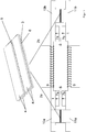
1 - den schematischen Aufbau des thermomagnetischen Generators mit Detailansicht des thermomagnetischen Bauelementes, und -
2 - eine einzelnes Bauelement aus magnetflussleitendem Material in Ansicht von unten (a), Vorderansicht (b) und Draufsicht (c).
-
1 - The schematic structure of the thermomagnetic generator with a detailed view of the thermomagnetic component, and -
2 - A single component made of magnetic flux-conducting material in view from below (a), front view (b) and top view (c).
Ausführungsbeispiel 1
Eine erfindungsgemäße Vorrichtung mit einem thermomagnetischen Generator weist zwischen horizontal angeordneten oberen und unteren Bauelementen aus magnetflussleitendem Material
Neben den Verbindungselementen mitt dem thermomagnetischen Material
Im Ruhezustand des thermomagnetischen Generators weisen die Verbindungselemente mit einem thermomagnetischen Material
Es konnte festgestellt werden, dass die Wärmeleitung für einen Temperaturausgleich mit einem Fluid in 0,5 mm dicken und stabförmig ausgebildeten thermomagnetischen Material nur 0,06 s erfordert. Eine deutlich längere Zeit von 0,19 s konnte in Vorversuchen ermittelt werden, sofern ein Fluid entlang einer aus dem Stand der Technik bekannten 10 mm langen Platte fließt, um die Temperatur am Ende der Platten zu ändern. Weitere 0,22 s benötigte das Fluid, um durch eine aus dem Stand der Technik bekannte Mischkammer zu fließen.It was found that the heat conduction for a temperature equalization with a fluid in 0.5 mm thick and rod-shaped thermomagnetic material requires only 0.06 s. A significantly longer time of 0.19 s could be determined in preliminary tests, provided that a fluid flows along a 10 mm long plate known from the prior art in order to change the temperature at the end of the plates. The fluid took another 0.22 s to flow through a mixing chamber known from the prior art.
BezugszeichenlisteList of reference symbols
- 11
- Bauelement aus magnetflussleitendem Material (Magnetjoch)Component made of material that conducts magnetic flux (magnetic yoke)
- 2a2a
- erstes Verbindungselement mit einem thermomagnetischen Materialfirst connecting element with a thermomagnetic material
- 2b2 B
- zweites Verbindungselement mit einem thermomagnetischen Materialsecond connecting element with a thermomagnetic material
- 33
- rechteckige Stäbe aus thermomagnetischem Materialrectangular bars made of thermomagnetic material
- 44th
- thermisch isolierendes Materialthermally insulating material
- 55
- DurchgangPassage
- 66th
- Öffnungopening
- 7a, 7b7a, 7b
- Bauelement aus hartmagnetischem MaterialComponent made of hard magnetic material
- 88th
- LuftspaltAir gap
- 99
- SpulenWash
- 10a, 10b10a, 10b
- Einlasskanal im ersten Bauelement aus magnetflussleitendem Material, z.B. WarmjochInlet channel in the first component made of material that conducts magnetic flux, e.g. warm yoke
- 11a, 11b11a, 11b
- Einlasskanal im zweiten Bauelement aus magnetflussleitendem Material, z.B. KaltjochInlet channel in the second component made of material that conducts magnetic flux, e.g. cold yoke
Claims (14)
Priority Applications (1)
| Application Number | Priority Date | Filing Date | Title |
|---|---|---|---|
| DE102020118370.4A DE102020118370B3 (en) | 2020-07-13 | 2020-07-13 | Device and method for converting thermal energy into electrical energy |
Applications Claiming Priority (1)
| Application Number | Priority Date | Filing Date | Title |
|---|---|---|---|
| DE102020118370.4A DE102020118370B3 (en) | 2020-07-13 | 2020-07-13 | Device and method for converting thermal energy into electrical energy |
Publications (1)
| Publication Number | Publication Date |
|---|---|
| DE102020118370B3 true DE102020118370B3 (en) | 2021-11-04 |
Family
ID=78267736
Family Applications (1)
| Application Number | Title | Priority Date | Filing Date |
|---|---|---|---|
| DE102020118370.4A Active DE102020118370B3 (en) | 2020-07-13 | 2020-07-13 | Device and method for converting thermal energy into electrical energy |
Country Status (1)
| Country | Link |
|---|---|
| DE (1) | DE102020118370B3 (en) |
Citations (11)
| Publication number | Priority date | Publication date | Assignee | Title |
|---|---|---|---|---|
| US396121A (en) | 1889-01-15 | Nikola Tesla | Thermo-Magnetic Motor | |
| US2619603A (en) | 1949-05-31 | 1952-11-25 | Technical Assets Inc | Thermomagnetic generator and refrigerator |
| DE3106520A1 (en) | 1981-02-21 | 1982-12-23 | Heinrich J. 5880 Lüdenscheid Brungsberg | Device for converting thermal energy into electrical or mechanical energy by means of a magnetic system |
| EP0308611A1 (en) | 1987-09-25 | 1989-03-29 | Hans-Wilhelm Stephan | Magnetocaloric, monostable and bistable generator for producing electrical power and for producing cold |
| DE3732312A1 (en) | 1987-09-25 | 1989-04-13 | Heinz Munk | Magnetocaloric inductor for producing electrical energy |
| JPH07107764A (en) | 1992-01-07 | 1995-04-21 | Hodaka Denshi Kogyo Kk | Thermomagnetic power generation apparatus using thermosensitive magnetic substance |
| WO2009133047A2 (en) | 2008-04-28 | 2009-11-05 | Basf Se | Thermomagnetic generator |
| WO2011018347A1 (en) | 2009-08-10 | 2011-02-17 | Basf Se | Heat exchanger bed made of a cascade of magnetocaloric materials |
| DE102012020486A1 (en) | 2011-10-28 | 2013-05-02 | Delta Electronics, Inc. | Thermomagnetic generator |
| EP2408033B1 (en) | 2010-07-13 | 2016-01-27 | Delta Electronics, Inc. | Power generation device |
| DE102017126803A1 (en) | 2016-11-18 | 2018-05-24 | Leibniz-Institut Für Festkörper- Und Werkstoffforschung Dresden E.V. | DEVICE AND METHOD FOR CONVERTING THERMAL ENERGY TO ELECTRICAL ENERGY |
-
2020
- 2020-07-13 DE DE102020118370.4A patent/DE102020118370B3/en active Active
Patent Citations (12)
| Publication number | Priority date | Publication date | Assignee | Title |
|---|---|---|---|---|
| US396121A (en) | 1889-01-15 | Nikola Tesla | Thermo-Magnetic Motor | |
| US2619603A (en) | 1949-05-31 | 1952-11-25 | Technical Assets Inc | Thermomagnetic generator and refrigerator |
| DE3106520A1 (en) | 1981-02-21 | 1982-12-23 | Heinrich J. 5880 Lüdenscheid Brungsberg | Device for converting thermal energy into electrical or mechanical energy by means of a magnetic system |
| EP0308611A1 (en) | 1987-09-25 | 1989-03-29 | Hans-Wilhelm Stephan | Magnetocaloric, monostable and bistable generator for producing electrical power and for producing cold |
| DE3732312A1 (en) | 1987-09-25 | 1989-04-13 | Heinz Munk | Magnetocaloric inductor for producing electrical energy |
| JPH07107764A (en) | 1992-01-07 | 1995-04-21 | Hodaka Denshi Kogyo Kk | Thermomagnetic power generation apparatus using thermosensitive magnetic substance |
| WO2009133047A2 (en) | 2008-04-28 | 2009-11-05 | Basf Se | Thermomagnetic generator |
| WO2011018347A1 (en) | 2009-08-10 | 2011-02-17 | Basf Se | Heat exchanger bed made of a cascade of magnetocaloric materials |
| EP2465119A1 (en) | 2009-08-10 | 2012-06-20 | Basf Se | Heat exchanger bed made of a cascade of magnetocaloric materials |
| EP2408033B1 (en) | 2010-07-13 | 2016-01-27 | Delta Electronics, Inc. | Power generation device |
| DE102012020486A1 (en) | 2011-10-28 | 2013-05-02 | Delta Electronics, Inc. | Thermomagnetic generator |
| DE102017126803A1 (en) | 2016-11-18 | 2018-05-24 | Leibniz-Institut Für Festkörper- Und Werkstoffforschung Dresden E.V. | DEVICE AND METHOD FOR CONVERTING THERMAL ENERGY TO ELECTRICAL ENERGY |
Non-Patent Citations (8)
| Title |
|---|
| BRILLOUIN, L. ; ISKENDERIAN, H.P.: Thermomagnetic generator. In: Electrical communication, Vol. 25, 1948, No. 3, S. 300-311. ISSN 0013-4252 (P) |
| Brillouin, L. and Iskenderian H.P., Thermomagnetic Generator, Electrical communication 25(8), 300-311 (1948) |
| DEEPAK, K. [u.a.]: Hybrid thermomagnetic oscillator for cooling and direct waste heat conversion to electricity. In: Applied Energy, Vol. 233-234, 2019, S. 312-320. - ISSN 0306-2619 (P); 1872-9118 (E). DOI: 10.1016/j.apenergy.2018.10.057 |
| DZEKAN, Daniel [u.a.]: Efficient and affordable thermomagnetic materials for harvesting low grade waste heat. 10-01-2020. arXiv:2001.03375. S. 1-24. URL: https://arxiv.org/pdf/2001.03375 [abgerufen am 2020-09-28] |
| Gueltig, M. et al. High-performance thermomagnetic generators based on heusler alloy films, Adv. Energy Mater. 7(5), 1601879 (2017) |
| GUELTIG, Marcel [u.a.]: High-performance thermomagnetic generators based on Heusler alloy films. In: Advanced Energy Materials, Vol. 7, 2017, No. 5, Artikelnummer: 1601879 (7 S.). - ISSN 1614-6832 (P); 1614-6840 (E). DOI: 10.1002/aenm.201601879. URL: https://onlinelibrary.wiley.com/doi/pdf/10.1002/aenm.201601879?casa_token=mBjwQ__BNi4AAAAA:Th2VzHyqobdY7pW97CgmwPxKpjoZfS80-NpOsjCJV2HTElPTwMIDERWdHXjUi6vdtCdrhx7bDidhV0Mr [abgerufen am 2020-09-28] |
| Tesla, N. US Patent 396121A (1889)] und Oszillatoren [Deepak, K., Varma, V., Prasanna, G., and Ramanujan, R. Hybrid thermomagnetic oscillator for cooling and direct waste heat conversion to electricity, Appl. Energy 233-234, 312 - 320 (2019) |
| WASKE, Anja [u.a.]: Energy harvesting near room temperature using a thermomagnetic generator with a pretzel-like magnetic flux topology. In: Nature Energy, Vol. 4, 2019, No. 1, S. 68-74. - ISSN 2058-7546 (E). DOI: 10.1038/s41560-018-0306-x |
Similar Documents
| Publication | Publication Date | Title |
|---|---|---|
| DE602005004272T2 (en) | DEVICE AND METHOD FOR PRODUCING HEATING UNITS WITH MAGNETO-CALORIC MATERIAL | |
| EP2465119B1 (en) | Heat-exchange bed based on a magnetocaloric materials cascade | |
| EP2272111B1 (en) | Thermomagnetic generator | |
| DE69200080T2 (en) | Static magnetic cooler. | |
| DE102008040281A1 (en) | Device and method for cooling components | |
| DE112006001628B4 (en) | Ferromagnetic shape memory alloy and its application | |
| DE3687290T2 (en) | METHOD AND DEVICE FOR LIQUID-METAL FLOW CONTROL. | |
| DE102012020486A1 (en) | Thermomagnetic generator | |
| EP3400642B1 (en) | Compressed air energy storage plant | |
| DE102018213497A1 (en) | Means for heat exchange with an elastocaloric element which encloses a fluid line | |
| DE102009054790A1 (en) | Superconducting device and associated vacuum container | |
| DE69008945T2 (en) | Device for the application of superconductivity. | |
| DE102012217990A1 (en) | Superconducting coil device and manufacturing method | |
| DE102013219536A1 (en) | Charging station for wireless energy-related coupling of an electrically driven vehicle | |
| DE112015006390T5 (en) | Cryostat and associated maglev transport vehicle and system | |
| DE102020118370B3 (en) | Device and method for converting thermal energy into electrical energy | |
| DE102017126803B4 (en) | DEVICE AND METHOD FOR CONVERSING THERMAL ENERGY INTO ELECTRICAL ENERGY | |
| CH406388A (en) | Magnetohydrodynamic generator | |
| EP2976830A2 (en) | Magnetic switching element in a magnetic circuit arranged in a defined manner including inductor coil and method for providing electrical energy | |
| DE4002286C2 (en) | Magnet drive, especially for a magnetic metering pump | |
| DE102011079725A1 (en) | Electric machine and method for its operation | |
| DE102016216655A1 (en) | reluctance motor | |
| DE102007023505B4 (en) | Apparatus for obtaining electrical energy from heat energy | |
| DE1054148B (en) | Arrangement in which the conductivity state of a conductor can be reversed | |
| DE1464415A1 (en) | Electromagnet |
Legal Events
| Date | Code | Title | Description |
|---|---|---|---|
| R012 | Request for examination validly filed | ||
| R016 | Response to examination communication | ||
| R018 | Grant decision by examination section/examining division | ||
| R020 | Patent grant now final | ||
| R081 | Change of applicant/patentee |
Owner name: HELMHOLTZ-ZENTRUM DRESDEN - ROSSENDORF E. V., DE Free format text: FORMER OWNER: LEIBNIZ-INSTITUT FUER FESTKOERPER- UND WERKSTOFFFORSCHUNG DRESDEN E.V. (IFW DRESDEN E.V.), 01069 DRESDEN, DE |
|
| R082 | Change of representative |