[Technisches Gebiet][Technical area]
Die vorliegende Erfindung betrifft eine rotierende elektrische Maschine.The present invention relates to a rotary electric machine.
[Hintergrund der Technik][Background of the technique]
Eine rotierende elektrische Maschine, wie sie in JP 2012-196095 A offenbart ist, ist bekannt. In dieser bekannten rotierenden elektrischen Maschine werden Schenkelpole eines Rotors magnetisiert, indem Ströme durch Rotorspulen geleitet werden, wobei diese Ströme durch eine elektromotorische Kraft induziert werden, die aufgrund von Raumharmonischen erzeugt wird, welche mit den durch einen Stator erzeugten Magnetischen Fluss überlagert sind, und die Ströme durch Dioden gleichgerichtet werden.A rotating electric machine, as in JP 2012-196095 A is disclosed is known. In this known rotary electric machine, salient poles of a rotor are magnetized by passing currents through rotor coils, which currents are induced by an electromotive force generated due to space harmonics superimposed on the magnetic flux generated by a stator, and the like Currents are rectified by diodes.
[Stand der Technik][State of the art]
[Patentliteratur][Patent Literature]
Patentliteratur 1: JP 2012-196095 A Patent Literature 1: JP 2012-196095 A
[Zusammenfassung der Erfindung]Summary of the Invention
[Technische Aufgabe][Technical task]
In der bekannten rotierenden elektrischen Maschine ist jedoch die in jedem der Rotoren erzeugte induzierte elektromotorische Kraft während eines Betriebs in einem Niedrigdrehzahlbereich klein, weil die Frequenz, mit der sich der magnetische Fluss ändert, niedrig ist. Somit werden die durch die Rotorspulen strömenden und durch die Dioden gleichgerichteten Ströme klein. Aus diesem Grund kann die bekannte rotierende elektrische Maschine während eines Betriebs bei niedrigen Rotordrehzahlen kein hohes Drehmoment erzeugen.However, in the known rotary electric machine, the induced electromotive force generated in each of the rotors during operation in a low speed region is small because the frequency with which the magnetic flux changes is low. Thus, the currents flowing through the rotor coils and rectified by the diodes become small. For this reason, the known rotary electric machine can not generate high torque during operation at low rotor speeds.
Ein Gegenstand der vorliegenden Erfindung besteht darin, eine rotierende elektrische Maschine bereitzustellen, die dazu geeignet ist, selbst während eines Betriebs bei niedrigen Rotordrehzahlen, ein ausreichend hohes Drehmoment zu erzeugen.An object of the present invention is to provide a rotary electric machine capable of generating a sufficiently high torque even during low rotor speed operation.
[Lösung der Aufgabe][Solution of the task]
Als eine Ausführungsform der vorliegenden Erfindung wird eine rotierende elektrische Maschine bereitgestellt, die Folgendes umfasst: einen um eine Rotationsachse gegenüber einem Stator drehbar montierten Rotor, wobei der Stator fähig ist, einen magnetischen Fluss zu erzeugen, indem eine Statorwicklung unter Spannung gesetzt wird, wobei der Rotor Folgendes umfasst: erste Schenkelpole, die Permanentmagnete aufweisen, eine Rotorwicklung, die die Induktion von Strömen, in Abhängigkeit einer mit dem magnetischen Fluss überlagerten hochfrequenten Harmonischen, erlaubt, wenn die hochfrequente Harmonische mit der Rotorwicklung zusammenwirkt; und Gleichrichter zur Gleichrichtung der Induktionsströme, und zweite Schenkelpole, um die die Rotorwicklung gewickelt ist.As one embodiment of the present invention, there is provided a rotary electric machine, comprising: a rotor rotatably mounted about a rotation axis opposite to a stator, the stator being capable of generating a magnetic flux by voltage-biasing a stator winding; A rotor comprising: first salient poles having permanent magnets; a rotor winding permitting the induction of currents in response to a high frequency harmonic superimposed with the magnetic flux when the high frequency harmonic is co-operating with the rotor winding; and rectifiers for rectifying the induced currents, and second salient poles around which the rotor winding is wound.
[Vorteilhafte Wirkung der Erfindung][Advantageous Effect of the Invention]
Die vorliegende Erfindung stellt eine rotierende elektrische Maschine bereit, die fähig ist, selbst bei niedrigen Rotordrehzahlen, ein ausreichend hohes Drehmoment zu erzeugen.The present invention provides a rotary electric machine capable of generating a sufficiently high torque even at low rotor speeds.
Figurenlistelist of figures
-
1 ist eine perspektivische Ansicht einer rotierenden elektrischen Maschine gemäß einer Ausführungsform der vorliegenden Erfindung. 1 FIG. 12 is a perspective view of a rotary electric machine according to an embodiment of the present invention. FIG.
-
2 ist eine Explosionsdarstellung der rotierenden elektrischen Maschine. 2 is an exploded view of the rotating electrical machine.
-
3 ist eine fragmentarische Explosionsdarstellung eines Stators der rotierenden elektrischen Maschine. 3 is a fragmentary exploded view of a stator of the rotary electric machine.
-
4 ist eine Explosionsdarstellung des Stators der rotierenden elektrischen Maschine, die ein Montageverfahren des Stators zeigt. 4 Fig. 10 is an exploded view of the stator of the rotary electric machine showing a stator mounting method.
-
5 ist eine fragmentarische Schnittdarstellung entlang einer kreisförmigen Linie entlang des Umfangs des Stators, die einen zusammengebauten Zustand der Statorkerne und einer Halterung im Stator der rotierenden elektrischen Maschine darstellt. 5 Fig. 12 is a fragmentary sectional view taken along a circular line along the circumference of the stator, showing an assembled state of the stator cores and a support in the stator of the rotary electric machine.
-
6 ist eine Explosionsdarstellung eines zweiten Rotors der rotierenden elektrischen Maschine. 6 is an exploded view of a second rotor of the rotating electrical machine.
-
7 ist ein Schaltplan einer Gleichrichterschaltung der rotierenden elektrischen Maschine. 7 is a circuit diagram of a rectifier circuit of the rotating electrical machine.
-
8 ist eine schematische Darstellung der rotierenden elektrischen Maschine. 8th is a schematic representation of the rotating electrical machine.
-
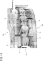
9 ist eine perspektivische Ansicht eines vom zweiten Rotor getrennten ersten Rotors der rotierenden elektrischen Maschine. 9 FIG. 12 is a perspective view of a first rotor of the rotary electric machine separated from the second rotor. FIG.
-
10(a) ist ein Ersatzschaltbild der d-Achse der rotierenden elektrischen Maschine. 10 (a) is an equivalent circuit diagram of the d-axis of the rotating electrical machine.
-
10(b) ist ein Ersatzschaltbild der q-Achse der rotierenden elektrischen Maschine. 10 (b) is an equivalent circuit diagram of the q-axis of the rotating electrical machine.
-
11 ist ein Schema, das den ersten und den zweiten Rotorabschnitt in einer ersten Konfiguration darstellt. 11 FIG. 12 is a diagram illustrating the first and second rotor sections in a first configuration. FIG.
-
12 ist ein Simulationsergebnis, das die Magnetflussdichte im Falle der ersten Konfiguration des ersten und des zweiten Rotorabschnitts darstellt. 12 is a simulation result representing the magnetic flux density in the case of the first configuration of the first and second rotor sections.
-
13 ist ein Schema, das den ersten und den zweiten Rotorabschnitt in einer zweiten Konfiguration darstellt. 13 FIG. 12 is a diagram illustrating the first and second rotor sections in a second configuration. FIG.
-
14 ist ein Simulationsergebnis, das die Magnetflussdichte im Falle der zweiten Konfiguration des ersten und des zweiten Rotorabschnitts darstellt. 14 is a simulation result representing the magnetic flux density in the case of the second configuration of the first and second rotor sections.
-
15 zeigt einen Vergleich eines statischen Drehmoments in einer Rotorposition, wobei eine Maschine gemäß der ersten Konfiguration mit einer Maschine gemäß der zweiten Konfiguration verglichen werden. 15 FIG. 12 shows a comparison of a static torque in a rotor position comparing a machine according to the first configuration with a machine according to the second configuration. FIG.
-
16(a) ist ein Schema, das die Flüsse darstellt, die gebildet werden, wenn die um die zweiten Schenkelpole gewickelten Spulen die zweiten Schenkelpole mit einer derartigen magnetischen Polarität magnetisieren, dass eine Flussabschwächung erzielt wird. 16 (a) FIG. 12 is a diagram illustrating the fluxes formed when the coils wound around the second salient poles magnetize the second salient poles with a magnetic polarity such that flux relaxation is achieved.
-
16(b) ist ein Schema, das die Flüsse darstellt, die gebildet werden, wenn die um die zweiten Schenkelpole gewickelten Spulen die zweiten Schenkelpole mit einer derartigen magnetischen Polarität magnetisieren, dass eine Flussverstärkung erzielt wird. 16 (b) FIG. 12 is a diagram illustrating the fluxes formed when the coils wound around the second salient poles magnetize the second salient poles with a magnetic polarity such that flux gain is achieved.
-
17 ist ein Simulationsergebnis, das die Magnetflussdichte in einem Fall darstellt, in dem die zweiten Schenkelpole zur Erzielung einer Flussabschwächung magnetisiert werden. 17 is a simulation result representing the magnetic flux density in a case where the second salient poles are magnetized to achieve flux relaxation.
-
18 ist ein Simulationsergebnis, das die Magnetflussdichte in einem Fall darstellt, in dem die zweiten Schenkelpole zur Erzielung einer Flussverstärkung magnetisiert werden. 18 is a simulation result representing the magnetic flux density in a case where the second salient poles are magnetized to obtain a flux gain.
-
19 ist ein Simulationsergebnis, das die Magnetflussdichte in einem Fall darstellt, in dem die Schaltung der Rotorwicklung in einem Leerlaufzustand liegt. 19 is a simulation result representing the magnetic flux density in a case where the circuit of the rotor winding is in an idle state.
-
20 zeigt einen Vergleich von Drehmoment/Phasen-Kennlinien, wobei eine den Fluss abschwächende Maschine und einen den Fluss verstärkende Maschine verglichen werden. 20 FIG. 12 shows a comparison of torque / phase characteristics comparing a flow-weakening engine and a flow-augmenting engine. FIG.
-
21 zeigt einen Vergleich eines Drehmoments bei einer magnetomotorischen Kraft des Stators, wobei die den Fluss abschwächende Maschine und die den Fluss verstärkende Maschine verglichen werden. 21 shows a comparison of a torque in a magnetomotive force of the stator, wherein the flow-weakening machine and the flow-enhancing machine are compared.
-
22 zeigt einen Vergleich der Drehmoment-/Drehzahl-Kennlinien, wobei die den Fluss abschwächende Maschine und die den Fluss verstärkende Maschine verglichen werden. 22 shows a comparison of the torque / speed characteristics, comparing the flow-weakening machine and the flow-enhancing machine.
-
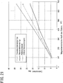
23 zeigt einen Vergleich der Außenleiterspannung bei einer Drehzahl, wobei die den Fluss abschwächende Maschine und die den Fluss verstärkende Maschine verglichen werden. 23 shows a comparison of the outer conductor voltage at a speed, wherein the flow-attenuating machine and the flow-enhancing machine are compared.
-
24(a) ist ein Vektordiagramm, das die den Fluss abschwächende Maschine mit verschiedenen Vektoren in einem mit dem Rotor verbundenen dq-Rahmen darstellt. 24 (a) Figure 12 is a vector diagram illustrating the flux-weakening machine with various vectors in a dq-frame connected to the rotor.
-
24(b) ist ein Vektordiagramm, das die den Fluss verstärkende Maschine mit verschiedenen Vektoren im dq-Rahmen darstellt. 24 (b) is a vector diagram representing the flux-enhancing machine with various vectors in the dq frame.
-
24(c) ist ein Vektordiagramm, das die den Fluss verstärkende Maschine mit verschiedenen Vektoren im dq-Rahmen darstellt, wobei die Norm eines Vektors des Eingangsstromes reduziert ist. 24 (c) Figure 4 is a vector diagram illustrating the flux-enhancing machine with various vectors in the dq frame, with the norm of a vector of the input current being reduced.
-
25 ist eine perspektivische Ansicht einer Änderung eines Rotors, die einen von einem zweiten Rotorabschnitt getrennten ersten Rotorabschnitt zeigt. 25 FIG. 15 is a perspective view of a change of a rotor showing a first rotor portion separated from a second rotor portion. FIG.
-
26 ist ein Diagramm, das die Flüsse darstellt, die gebildet werden, wenn die um die zweiten Schenkelpole des zweiten Rotorabschnitts gewickelten Spulen die zweiten Schenkelpole mit einer derartigen magnetischen Polarität magnetisieren, dass eine Flussverstärkung erzielt wird. 26 FIG. 12 is a diagram illustrating the fluxes formed when the coils wound around the second salient poles of the second rotor section magnetize the second salient poles with a magnetic polarity such that flux gain is achieved.
[Detaillierte Beschreibung][Detailed description]
Vorliegend wird eine rotierende elektrische Maschine offenbart. Die Maschine umfasst: einen um eine Rotationsachse gegenüber einem Stator drehbar montierten Rotor, wobei der Stator fähig ist, einen magnetischen Fluss zu erzeugen, indem eine Statorwicklung unter Spannung gesetzt wird, wobei der Rotor Folgendes umfasst: erste Schenkelpole, die Permanentmagnete aufweisen, eine Rotorwicklung, die die Induktion von Strömen, in Abhängigkeit einer mit dem magnetischen Fluss überlagerten hochfrequenten Harmonischen, erlaubt; und Gleichrichter zur Gleichrichtung der Induktionsströme, und zweite Schenkelpole, um die die Rotorwicklung gewickelt ist. Somit kann die rotierende elektrische Maschine selbst bei niedrigen Rotordrehzahlen, ein ausreichend hohes Drehmoment erzeugen.In the present case, a rotating electrical machine is disclosed. The machine comprises: a rotor rotatably mounted about a rotational axis opposite a stator, the stator being capable of generating a magnetic flux by stressing a stator winding, the rotor comprising: first salient poles having permanent magnets, a rotor winding which allows the induction of currents in response to a high-frequency harmonic superimposed with the magnetic flux; and rectifiers for rectifying the induced currents, and second salient poles around which the rotor winding is wound. Thus, the rotating electric machine can generate a sufficiently high torque even at low rotor speeds.
[Ausführungsform(en)][Embodiment (s)]
In der Folge werden beispielhafte Ausführungsformen der Erfindung unter Bezugnahme auf die beigefügten Zeichnungen beschrieben, wobei dieselben Bezugszeichen gleiche Elemente bezeichnen.In the following, exemplary embodiments of the invention will be described with reference to the accompanying drawings, wherein like reference numerals designate like elements.
Eine mit 1 bezeichnete rotierende elektrische Maschine oder Maschine mit einem inneren doppelten Rotor mit Permanentmagneten, einem einzelnen Stator, und axialem Fluss gemäß der vorliegenden Ausführungsform ist in 1 in einer perspektivischen Ansicht und in 2 in einer Explosionsdarstellung gezeigt. Die Maschine 1 umfasst einen Stator 10 und einen um eine Rotationsachse gegenüber dem Stator 10 drehbar montierten Rotor 20. Ein dreiphasiger elektrischer Eingang, d.h. dreiphasige Wechselströme, versorgt den Stator 10 mit Leistung. Im Einzelnen kann der Stator 10, wenn die Spulen einer Statorwicklung 11 unter Strom gesetzt werden, einen magnetischen Fluss erzeugen. Der Rotor 20 umfasst einen ersten Rotorabschnitt 20A und einen zweiten Rotorabschnitt 20B.A rotary electric machine denoted by 1 or having an inner double permanent magnet rotor, a single stator, and axial flux according to the present embodiment is shown in FIG 1 in a perspective view and in 2 shown in an exploded view. The machine 1 includes one stator 10 and one about an axis of rotation relative to the stator 10 rotatably mounted rotor 20 , A three-phase electrical input, ie three-phase alternating currents, supplies the stator 10 with power. In detail, the stator 10 when the coils of a stator winding 11 be energized, generate a magnetic flux. The rotor 20 includes a first rotor section 20A and a second rotor section 20B ,
In der vorliegenden Ausführungsform ist die Maschine 1 eine Maschine mit Axialspalt, in der der Rotor 20 in Bezug auf die Rotationsachse axial neben dem Stator 10 liegt, aber vom Stator 10 durch einen axialen Spalt axial beabstandet ist. Wie in der Folge beschrieben, wird keine externe Stromversorgung des Rotors 20 benötigt.In the present embodiment, the machine is 1 a machine with axial gap in which the rotor 20 with respect to the axis of rotation axially adjacent to the stator 10 lies, but from the stator 10 axially spaced by an axial gap. As described below, there is no external power supply to the rotor 20 needed.
(Stator)(Stator)
Ebenfalls bezugnehmend auf die 3 umfasst der Stator 10 eine Vielzahl von Statorkernen 12, die in Umfangsrichtung gleichmäßig verteilt sind, wobei Spulen der Statorwicklungen 11 um die Statorkerne 12 gewickelt sind, und eine Halterung 13, um die Statorkerne 12 derart zu halten, dass sie voneinander magnetisch getrennt sind. In diesem Beispiel sind die Statorkerne 12 voneinander getrennte Einzelstücke. Sie können aber auch einstückig ausgebildet sein, vorausgesetzt, dass sie magnetisch getrennt sind.Referring also to the 3 includes the stator 10 a variety of stator cores 12 which are evenly distributed in the circumferential direction, wherein coils of the stator windings 11 around the stator cores 12 are wrapped, and a bracket 13 to the stator cores 12 such that they are magnetically separated from each other. In this example, the stator cores 12 separate individual pieces. But they can also be integrally formed, provided that they are magnetically separated.
In der vorliegenden Ausführungsform bestehen die Statorkerne 12 aus einem aus Pulver gebildeten magnetischen Kern, der sich aus einem Formpressen eines feinen ferromagnetischen metallischen Pulvers ergibt. Um eine hervorragende elektrische Isolierung zu gewährleisten, sind die Statorkerne 12 mit einem Harzpulver pulverbeschichtet. Um die Statorkerne 12 befinden sich konzentriert gewickelte W-Phasen-Spulen, V-Phasen-Spulen und U-Phasen-Spulen.In the present embodiment, the stator cores exist 12 of a magnetic core formed of powder resulting from molding a fine ferromagnetic metallic powder. To ensure excellent electrical insulation, are the stator cores 12 powder-coated with a resin powder. Around the stator cores 12 There are concentrated wound W-phase coils, V-phase coils and U-phase coils.
Im Stator 10 sind die Statorkerne 12 magnetisch voneinander getrennt, da, wie zuvor beschrieben, die Statorkerne 12 voneinander getrennte Einzelstücke sind, wobei die Halterung 13, die aus einem nicht magnetischen Material besteht, die Statorkerne 12 hält. Dies sorgt dafür, dass sich der Fluss der jeden der Statorkerne 12 verlassenden zweiten Raumharmonischen, im Vergleich zu einem herkömmlichen Stator, der ein hinteres Joch umfasst, das einen Weg für Streuflüsse der zweiten Raumharmonischen von einem Statorkern zum nächsten benachbarten Statorkern frei lässt, wirksam und erfolgreich mit den in der Folge beschriebenen zweiten Schenkelpolen 32 verkettet, weil ein solcher Streufluss durch ein hinteres Joch verhindert wird. Außerdem sorgt die konzentriert gewickelte Statorwicklung 11 dafür, dass sich der von beiden Seiten jedes der Statorkerne 12 austretende Fluss der zweiten Raumharmonischen wirksam und erfolgreich mit den zweiten Schenkelpolen 32 verkettet. Die Herstellung der Statorkerne 12 kann vereinfacht werden, indem ein hinteres Joch aus einem magnetischen Material verwendet wird.In the stator 10 are the stator cores 12 magnetically separated from each other because, as previously described, the stator cores 12 are separate individual pieces, wherein the holder 13 , which consists of a non-magnetic material, the stator cores 12 holds. This ensures that the flow of each of the stator cores 12 leaving second space harmonics effectively and successfully with the second salient poles described below, as compared with a conventional stator including a rear yoke which leaves a path for leakage fluxes of the second space harmonic from one stator core to the next adjacent stator core 32 linked, because such leakage flux is prevented by a rear yoke. In addition, the concentrated wound stator winding ensures 11 for that of each side of each of the stator cores 12 exiting flow of the second space harmonic effectively and successfully with the second salient poles 32 concatenated. The production of the stator cores 12 can be simplified by using a rear yoke made of a magnetic material.
Weiter bezugnehmend auf die 3 umfasst jeder Statorkerne 12 einen ersten und einen zweiten (d.h. zwei) Statorkernabschnitt 12A und 12B, die einer Teilung gemäß einem in Bezug auf die Rotationsachse senkrechten Schnitt durch den Statorkern 12 entsprechen.Further referring to the 3 each includes stator cores 12 a first and a second (ie, two) stator core section 12A and 12B which is a pitch in accordance with a section through the stator core which is perpendicular to the axis of rotation 12 correspond.
Der Stator 10 umfasst die Halterung 13. Die Halterung 13 ist ringförmig und besteht aus einem nicht magnetischen Material, wie zum Beispiel Edelstahl. Die Halterung 13 ist dazu ausgebildet, die Statorkerne 12 zu halten, um die Spulen der Statorwicklung 11 gewickelt sind. Die Halterung 13 ist mit einer in Umfangsrichtung angeordneten oder sich in Umfangsrichtung erstreckenden Reihe von Halterungslöchern 13a ausgebildet, die gleichmäßig verteilt sind und jeweils einen der Statorkerne 12 halten, d.h. jeweils eine erste sich in Umfangsrichtung erstreckende Reihe von ersten Statorkernabschnitten 12A und eine zweite axial ausgerichtete sich in Umfangsrichtung erstreckende Reihe von zweiten Statorkernabschnitten 12B. Ein nicht dargestelltes Motorgehäuse kann an seinem äußeren Umfang mit der Halterung 13 verbunden werden.The stator 10 includes the bracket 13 , The holder 13 is annular and made of a non-magnetic material, such as stainless steel. The holder 13 is designed to the stator cores 12 to hold around the coils of the stator winding 11 are wound. The holder 13 is provided with a circumferentially extending or circumferentially extending series of mounting holes 13a formed, which are evenly distributed and each one of the stator cores 12 hold, ie in each case a first circumferentially extending series of first stator core sections 12A and a second axially aligned circumferentially extending series of second stator core sections 12B , An unillustrated motor housing may at its outer periphery with the holder 13 get connected.
In der Folge wird das Montageverfahren des Stators 10 unter Bezugnahme auf die 4 beschrieben.As a result, the assembly process of the stator 10 with reference to the 4 described.
Die Spulen der Statorwicklung 11 sind Spulen mit einer Alphawicklung und sind zur Aufnahme der Statorkerne 12 geformt. Bei Alphawicklungen können sich ein Anfang und ein Ende eines Drahts in derselben Richtung nach außen erstrecken.The coils of the stator winding 11 are coils with an alpha winding and are for accommodating the stator cores 12 shaped. In alpha windings, a beginning and an end of a wire may extend outward in the same direction.
Bei einer Alphawicklung der Spulen des Stators 11 besteht ein besseres Flächenverhältnis des Querschnitts eines Drahts. Keine anderen Spulen können dichter gewickelt werden. Die Alphawicklung der Spulen vereinfacht deren externe Verbindung, weil sich der Anfang und das Ende jedes Drahts vom äußeren Umfang des Stators 10 in dieselbe Richtung erstrecken.In an alpha winding of the coils of the stator 11 There is a better area ratio of the cross section of a wire. No other coils can be wound more tightly. The alpha winding of the coils simplifies their external connection because the beginning and the end of each wire from the outer circumference of the stator 10 extend in the same direction.
3 zeigt einen Teil einer ersten in Umfangsrichtung angeordneten Reihe von W-, V- und U-Phasen-Spulen der Statorwicklung 11 und einer zweiten durch einen Spalt 11a axial beabstandeten in Umfangsrichtung angeordneten Reihe von W-, V- und U-Phasen-Spulen der Statorwicklung 11. Im zusammengebauten Zustand ist die Halterung 13 in diesem Spalt 11a zwischen der ersten und der zweiten Reihe von W-, V-, und U-Phasen-Spulen angeordnet. 3 shows a portion of a first circumferentially arranged series of W, V and U phase coils of the stator winding 11 and a second through a gap 11a axially spaced circumferentially arrayed W, V and U phase coils of the stator winding 11 , When assembled, the bracket 13 in this gap 11a disposed between the first and second series of W, V, and U-phase coils.
Die Halterung 13 umfasst eine in Umfangsrichtung angeordnete Reihe von Halterungslöchern 13a, die sich jeweils radial und nach innen, in einer radialen Richtung, von einem radial äußeren breiten Rand zu einem radial inneren engen Rand erstrecken. Die W-, V- und U-Phasenspulen der ersten oberen sich in Umfangsrichtung erstreckenden Reihe und die W-, V- und U-Phasenspulen der zweiten in Umfangsrichtung angeordneten Reihe sind auf der oberen und der unteren Seite der Halterung 13 angeordnet, so dass jede der durch die Phasenspulen der ersten in Umfangsrichtung angeordneten Reihe umgebenen Öffnungen mit einem der Halterungslöcher 13a und außerdem mit einer Öffnung axial ausgerichtet ist, die durch die Phasenspulen der zweiten axial beabstandeten in Umfangsrichtung angeordneten Reihe begrenzt oder umgeben ist. The holder 13 comprises a circumferentially arranged series of mounting holes 13a each extending radially and inwardly, in a radial direction, from a radially outer wide edge to a radially inner narrow edge. The W, V and U phase coils of the first upper circumferentially extending row and the W, V and U phase coils of the second circumferentially arranged row are on the upper and lower sides of the holder 13 arranged so that each of the openings surrounded by the phase coils of the first row arranged in the circumferential direction with one of the mounting holes 13a and is also axially aligned with an opening bounded or surrounded by the phase coils of the second axially spaced circumferentially array.
In der vorhergehenden Beschreibung und in der folgenden Beschreibung bezieht sich der Begriff „radiale Richtung“ auf eine Richtung, die senkrecht zur Rotationsachse des Rotors 20 verläuft. Der Begriff „radial außen“ und der Begriff „radial innen“ bezeichnen von der Rotationsachse in einer radialen Richtung senkrecht zur Rotationsachse jeweils entfernte und weniger entfernte Positionen.In the foregoing description and in the following description, the term "radial direction" refers to a direction perpendicular to the axis of rotation of the rotor 20 runs. The term "radially outward" and the term "radially inward" respectively designate remote and less distant positions from the axis of rotation in a radial direction perpendicular to the axis of rotation.
Da die Phasenspulen der Statorwicklung 11 auf beiden Seiten der Halterung 13 angeordnet sind, werden die ersten Statorkernabschnitte 12A durch die durch die Phasenspulen begrenzten Öffnungen in die Halterungslöcher 13a axial eingeführt und die zweiten Statorkernabschnitte 12B werden durch die durch die Phasenspulen begrenzten Öffnungen in die Halterungslöcher 13a eingeführt, bis sie innerhalb der Halterungslöcher 13a aufeinander treffen, wodurch die Phasenspulen der Statorwicklung 11 gegen die Halterung 13 gedrückt werden (siehe 5).Because the phase coils of the stator winding 11 on both sides of the bracket 13 are arranged, the first stator core sections 12A through the openings bounded by the phase coils in the mounting holes 13a axially inserted and the second stator core sections 12B become through the openings defined by the phase coils in the mounting holes 13a Introduced until they are inside the mounting holes 13a meet, causing the phase coils of the stator winding 11 against the holder 13 be pressed (see 5 ).
Ein Vergießen der zusammengebauten Anordnung der Phasenspulen der Statorwicklung 11 mit den ersten und zweiten Statorkernabschnitten 12A und 12B und der Halterung 13 wird bevorzugt. Im Vergussverfahren wird die Anordnung in eine Form eingelegt, die dann mit einem isolierenden flüssigen Harz gefüllt wird, wodurch die Anordnung geschützt wird. Die Form ist Teil des fertigen Stators 10 und kann elektromagnetische Vibrationen einschränken und die thermische Leitfähigkeit zur Abkühlung verbessern.A potting of the assembled arrangement of the phase coils of the stator winding 11 with the first and second stator core sections 12A and 12B and the holder 13 is preferred. In the potting process, the assembly is placed in a mold, which is then filled with an insulating liquid resin, thereby protecting the assembly. The mold is part of the finished stator 10 and can limit electromagnetic vibrations and improve the thermal conductivity for cooling.
Wie zuvor beschrieben, sind die Statorkerne 12 in der vorliegenden Ausführungsform zur Isolierung mit einem Harzpulver pulverbeschichtet. Die Spulen der Statorwicklung 11 können aber auch über Isolatoren um die Statorkerne 12 gewickelt werden, wobei die Isolatoren durch Formung aus einem nicht magnetischen Material, wie zum Beispiel einem isolierenden Harz, gebildet werden, um eine hervorragende Isolierung der Statorkerne 12 zu bieten.As previously described, the stator cores are 12 in the present embodiment, powder-coated for isolation with a resin powder. The coils of the stator winding 11 But you can also use insulators around the stator cores 12 wherein the insulators are formed by molding from a non-magnetic material such as an insulating resin, for excellent insulation of the stator cores 12 to offer.
5 ist eine schematische Schnittansicht des wie soeben beschrieben zusammengebauten Stators 10. 5 FIG. 12 is a schematic sectional view of the stator assembled as just described. FIG 10 ,
Wie in 5 gezeigt, ist jeder der ersten und zweiten Statorkernabschnitte 12A und 12B mit einer Kante oder einem hervorragenden Rand 12a ausgebildet, um die entsprechende Spule der Statorwicklung 11 in Position zu halten. Dadurch wird verhindert, dass die Spulen der Statorwicklung 11 aus den ersten und zweiten Statorkernabschnitten 12A und 12B herausrutschen.As in 5 is shown, each of the first and second stator core sections 12A and 12B with an edge or a prominent edge 12a formed to the corresponding coil of the stator winding 11 to hold in position. This will prevent the coils of the stator winding 11 from the first and second stator core sections 12A and 12B slip out.
Der oben beschriebene Stator 10 ist fähig, ein rotierendes Magnetfeld zu erzeugen, indem die Spulen der Statorwicklung 11 mit einem dreiphasigen Wechselstrom versorgt werden. Der magnetische Fluss des Stators 10 verkettet sich mit dem Rotor 20, was die Erzeugung eines am Rotor 20 angewendeten Drehmoments verursacht.The stator described above 10 is capable of generating a rotating magnetic field by the coils of the stator winding 11 be supplied with a three-phase alternating current. The magnetic flux of the stator 10 linked to the rotor 20 what the generation of a rotor 20 applied torque caused.
(Rotor)(Rotor)
Wieder bezugnehmend auf die 1 und 2 umfasst der Rotor 20 einen ersten Rotorabschnitt 20A und einen zweiten Rotorabschnitt 20B.Referring again to the 1 and 2 includes the rotor 20 a first rotor section 20A and a second rotor section 20B ,
Der erste Rotorabschnitt 20A grenzt axial an einer Seite des Stators 10 an und der zweite Rotorabschnitt 20B grenzt axial an der gegenüberliegenden Seite des Stators 10 an, so dass sie um die Rotationsachse rotieren können.The first rotor section 20A is axially adjacent to one side of the stator 10 on and the second rotor section 20B is axially adjacent to the opposite side of the stator 10 so that they can rotate about the axis of rotation.
In der vorliegenden Ausführungsform ist der erste Rotorabschnitt 20A von der einen Seite des Stators 10 durch einen axialen Luftspalt axial beabstandet, während der zweite Rotorabschnitt 20B von der gegenüberliegenden Seite des Stators 10 durch einen axialen Luftspalt axial beabstandet ist, so dass der Stator 10 zwischen ihnen liegt. Der erste und der zweite Rotorabschnitt 20A und 20B weisen dieselbe Struktur und Anordnung auf. Demnach wird in der Folge nur der zweite Rotorabschnitt 20B beschrieben, und die Beschreibung des ersten Rotorabschnitts 20A der Kürze halber unterlassen.In the present embodiment, the first rotor section is 20A from one side of the stator 10 axially spaced by an axial air gap, while the second rotor section 20B from the opposite side of the stator 10 axially spaced by an axial air gap, so that the stator 10 lies between them. The first and second rotor sections 20A and 20B have the same structure and arrangement. Accordingly, only the second rotor section will follow in the sequence 20B described, and the description of the first rotor section 20A omit for the sake of brevity.
Bezugnehmend auf die 2 und die 6 umfasst der zweite Rotorabschnitt 20B einen ringförmigen Rotorkern 21, eine Rotorwicklung 23 und Gleichrichterschaltungen 24 (siehe 7).Referring to the 2 and the 6 includes the second rotor section 20B an annular rotor core 21 , a rotor winding 23 and rectifier circuits 24 (please refer 7 ).
Der Rotorkern 21 umfasst eine sich in Umfangsrichtung erstreckende oder angeordnete Reihe von Schenkelpolen 22. Der Rotorkern 21 ist ein Kern aus einem magnetischen Pulver, der aus komprimierten ferromagnetischen feinen Pulvern besteht.The rotor core 21 includes a circumferentially extending or arranged series of salient poles 22 , The rotor core 21 is a core of a magnetic powder consisting of compressed ferromagnetic fine powders.
Die sich in Umfangsrichtung erstreckende Reihe von Schenkelpolen 22 ist eine Reihe von abwechselnden ersten Schenkelpolen 31 und zweiten Schenkelpolen 32. Jeder erste Schenkelpol 31 weist einen Permanentmagnet 30 auf. Um jeden zweiten Schenkelpol 32 ist eine Rotorwicklung 23 gewickelt. Wie in 2 am besten sichtbar, sind die ersten und die zweiten Schenkelpole 31 und 32 abwechselnd angeordnet.The circumferentially extending series of salient poles 22 is a series of alternating first salient poles 31 and second salient poles 32 , Every first salient pole 31 has a permanent magnet 30 on. For every second leg pole 32 is a rotor winding 23 wound. As in 2 The best visible are the first and second salient poles 31 and 32 arranged alternately.
Jeder der ersten Schenkelpole 31 weist ein Paar von hervorragenden Rippen 31a auf. Die Rippen 31a jedes Paars ragen in derselben Richtung wie jeder der zweiten Schenkelpole 32 hervor. Ein Permanentmagnet 30 ist zwischen den Rippen 31a jedes Paars eingebettet und ist anhand eines Klebstoffs mit einem der ersten Schenkelpole 31 verklebt. Beispiele eines solchen Klebstoffs sind siliziumbasierte Klebstoffe, Acrylklebstoffe und Epoxid-Klebstoffe. Der Klebstoff ist eines der oben erwähnten Klebstoffe, ist aber nicht auf diese beschränkt.Each of the first salient poles 31 has a pair of excellent ribs 31a on. Ribs 31a each pair protrude in the same direction as each of the second salient poles 32 out. A permanent magnet 30 is between the ribs 31a embedded each pair and is based on an adhesive with one of the first salient poles 31 bonded. Examples of such an adhesive are silicon-based adhesives, acrylic adhesives, and epoxy adhesives. The adhesive is one of the above-mentioned adhesives, but is not limited to these.
Die Rippen 31a jedes Paars dienen der Einschränkung der Umfangsbewegung des Permanentmagnets 30. Außerdem dienen sie der Halterung des Permanentmagneten 30 in der richtigen Position bis der Permanentmagnet 30 mit einem der ersten Schenkelpole 31 verklebt ist. Somit wird zur Verklebung keine exklusive Vorrichtung zur Positionierung jedes der Permanentmagnete 30 an einem der ersten Schenkelpole 31 benötigt. Dies verbessert die Arbeitseffizienz während des Klebevorgangs, wodurch Herstellungskosten reduziert werden.Ribs 31a each pair serve to limit the circumferential movement of the permanent magnet 30 , In addition, they serve to hold the permanent magnet 30 in the correct position until the permanent magnet 30 with one of the first salient poles 31 is glued. Thus, bonding does not become an exclusive device for positioning each of the permanent magnets 30 at one of the first salient poles 31 needed. This improves the working efficiency during the bonding operation, thereby reducing manufacturing costs.
Die zweiten Schenkelpole 32 ragen von der dem Stator 10 gegenüberliegenden Oberfläche 21a des Statorkerns 21 axial in Richtung des Stators 10 hervor. Zwischen den zwei in Umfangsrichtung benachbarten Schenkelpolen, nämlich zwischen jedem der zweiten Schenkelpole 32 und dem daran angrenzenden ersten Schenkelpol 31, befindet sich ein Rotorschlitz 34. Die Spulen der Rotorwicklung 23 sind in den Rotorschlitzen 24 um die zweiten Schenkelpole 32 gewickelt.The second salient poles 32 protrude from the stator 10 opposite surface 21a of the stator core 21 axially in the direction of the stator 10 out. Between the two circumferentially adjacent salient poles, namely between each of the second salient poles 32 and the first salient pole adjacent thereto 31 , there is a rotor slot 34 , The coils of the rotor winding 23 are in the rotor slots 24 around the second salient poles 32 wound.
Die Rotorwicklung 23 erlaubt eine Induktion von Wechselströmen in Abhängigkeit einer mit dem magnetischen Fluss des Stators 10 überlagerten hochfrequenten Harmonischen. Im Einzelnen umfasst die Rotorwicklung 23 Induktionsspulen 23a und Feldspulen 23b.The rotor winding 23 allows induction of alternating currents as a function of the magnetic flux of the stator 10 superimposed high-frequency harmonics. In detail, the rotor winding comprises 23 inductors 23a and field coils 23b ,
Die Induktionsspulen 23a sind vom Stator 10 axial getrennt aber am Stator 10 angrenzend angeordnet. In jeder der Induktionsspulen 23a wird durch die Zusammenwirkung mit einer mit dem magnetischen Fluss des Stators 10 überlagerten hochfrequenten Harmonischen, d.h. einer Raumharmonischen, ein Strom erzeugt. Die Induktionsspulen 23a sind über in der Folge beschriebene Gleichrichter mit den Feldspulen 23b verbunden.The induction coils 23a are from the stator 10 axially separated but at the stator 10 arranged adjacent. In each of the induction coils 23a is due to the interaction with one with the magnetic flux of the stator 10 superimposed high-frequency harmonics, ie a room harmonic, generates a current. The induction coils 23a are about rectifiers described below with the field coils 23b connected.
Es ist bekannt, dass das am Stator 10 erzeugte rotierende Magnetfeld zusätzlich zur Grundschwingung eine Raumharmonische enthält. Die Raumharmonische ist nicht mit der Grundschwingung synchronisiert.It is known that on the stator 10 generated rotating magnetic field in addition to the fundamental vibration contains a space harmonic. The space harmonic is not synchronized with the fundamental.
Die Feldspulen 23b sind dazu eingerichtet, zur Magnetisierung der zweiten Schenkelpole 32, Feldströme zu leiten, die sich aus der Gleichrichtung der induzierten Ströme durch die Gleichrichterschaltungen 24 (in 7 gezeigt) ergeben.The field coils 23b are arranged to magnetize the second salient poles 32 To conduct field currents resulting from the rectification of the induced currents through the rectifier circuits 24 (in 7 shown).
Jede der Gleichrichterschaltungen 24 ist eine Schaltung zur Gleichrichtung von durch die Rotorwicklungen 23 geleiteten induzierten Wechselströmen. Im Einzelnen sind diese Schaltungen dazu ausgebildet, in den Induktionsspulen 23a induzierte Wechselströme gleichzurichten, um einen Gleichstrom den Feldspulen 23b zuzuführen (siehe 7).Each of the rectifier circuits 24 is a circuit for rectification by the rotor windings 23 directed induced alternating currents. In particular, these circuits are designed to be in the induction coils 23a rectified induced AC currents to a DC current to the field coils 23b to be supplied (see 7 ).
Weiter bezugnehmend auf die 7 umfasst die Gleichrichterschaltung 24 zwei Dioden D1 und D2 als Gleichrichter. Ebenfalls bezugnehmend auf die 8 ist jede der Gleichrichterschaltungen 24 ein geschlossener Kreis, der die Dioden D1 und D2, eine Induktionsspule 23a und eine Feldspule 23b, die um einen zweiten Schenkelpol 32 am ersten Rotorabschnitt 20A gewickelt sind, und eine Induktionsspule 23a und eine Feldspule 23b, die um einen zweiten Schenkelpol 32 am zweiten Rotorabschnitt 20B gewickelt sind, miteinander verbindet.Further referring to the 7 includes the rectifier circuit 24 two diodes D1 and D2 as a rectifier. Referring also to the 8th is each of the rectifier circuits 24 a closed circle, the diodes D1 and D2 , an induction coil 23a and a field coil 23b around a second salient pole 32 at the first rotor section 20A are wound, and an induction coil 23a and a field coil 23b around a second salient pole 32 on the second rotor section 20B are wound, connecting with each other.
Da der zweite Rotorabschnitt 20B um eine Polteilung (siehe 8) in Umfangsrichtung vom ersten Rotorabschnitt 20A versetzt ist, verbindet jede der Gleichrichterschaltungen 24 einen Satz von Induktions- und Feldspulen 23a und 23b um einen zweiten Schenkelpol 32 am ersten Rotorabschnitt 20A mit Induktions- und Feldspulen23a und 23b um einen benachbarten Schenkelpol 32 am zweiten Rotorabschnitt 20B. Somit ist die Anzahl von durch die Maschine 1 benötigten Gleichrichterschaltungen eine Funktion der Anzahl von Polen.Since the second rotor section 20B around a pole pitch (see 8th ) in the circumferential direction of the first rotor section 20A is offset, each of the rectifier circuits connects 24 a set of induction and field coils 23a and 23b around a second salient pole 32 at the first rotor section 20A with induction and field coils 23a and 23b around an adjacent salient pole 32 on the second rotor section 20B , Thus, the number of passes through the machine 1 required rectifier circuits a function of the number of poles.
Die Dioden D1 und D2 sind in einem nicht gezeigten Diodengehäuse untergebracht und am Rotor 20 montiert. Die Dioden D1 und D2 können innerhalb des Rotors 20 montiert sein. Die Gleichrichter sind Dioden, sind aber nicht darauf beschränkt und können Halbleitervorrichtungen, wie z.B. Schaltgeräte, sein.The diodes D1 and D2 are housed in a diode housing, not shown, and on the rotor 20 assembled. The diodes D1 and D2 can be inside the rotor 20 be mounted. The rectifiers are diodes but are not limited thereto and may be semiconductor devices such as switching devices.
Die Gleichrichterschaltung 24 ist ein Vollwellengleichrichter vom Typ Mittelpunktschaltung, der nach einer Wechselrichtung einer der zwei induzierten Eingangs-ACs zur Erzeugung einer 180° Phasendifferenz, positive Halbwellen von zwei induzierten Eingangswechselströmen (AC) anhand von zwei Dioden D1 und D2 in einen pulsierenden Ausgangsgleichstrom (DC) wandelt.The rectifier circuit 24 is a full-wave rectifier of the type of mid-point switching, which, following an alternating direction of one of the two induced input ACs to produce a 180 ° phase difference, positive half-waves of two induced input alternating currents (AC) using two diodes D1 and D2 into a pulsating DC output current (DC).
Anhand der Dioden D1 und D2 wandelt die Gleichrichterschaltung 24 die induzierten Eingangs-Wechselströme, welche in zwei Induktionsspulen 23a induziert werden, in einen Ausgangs-Gleichstrom. Der Ausgangs-Gleichstrom wird den Feldspulen 23b als Feldstrom zugeführt, wodurch die Feldspulen 23b die zugeordneten zweiten Schenkelpole 32 magnetisieren. On the basis of the diodes D1 and D2 converts the rectifier circuit 24 the induced input alternating currents, which in two induction coils 23a be induced in an output DC. The output DC becomes the field coils 23b fed as a field current, causing the field coils 23b the associated second salient poles 32 magnetize.
In der vorliegenden Ausführungsform sind die Feldspulen 23b derart gewickelt, dass jeder der zweiten Schenkelpole 32 auf jedem der ersten und zweiten Rotorabschnitte 20A und 20B an einer inneren, dem Stator 10 gegenüberliegenden Fläche einen Magnetpol S und an einer äußeren Fläche einen Magnetpol N (siehe 9) bildet, so dass die Pole in der axialen Richtung ausgerichtet sind.In the present embodiment, the field coils 23b wrapped so that each of the second salient poles 32 on each of the first and second rotor sections 20A and 20B on an inner, the stator 10 a magnetic pole S and on an outer surface a magnetic pole N (see 9 ) so that the poles are aligned in the axial direction.
Wie zuvor beschrieben, wird in Abhängigkeit einer mit dem am Stator 10 erzeugten magnetischen Fluss überlagerten Raumharmonischen ein Strom in jeder der Induktionsspulen 23a induziert. Die Raumharmonische wird in Abhängigkeit einer Änderung der magnetischen Reluktanz in einem Luftspalt zwischen dem Stator 10 und jedem der ersten Rotorabschnitte 20A und zweiten Rotorabschnitte 20B zur Rotation der ersten und zweiten Rotorabschnitte 20A und 20B erzeugt, welche die in Umfangsrichtung angeordneten Reihen von abwechselnden ersten und zweiten Schenkelpolen 31 und 32 aufweisen.As described above, depending on a with the stator 10 generated magnetic flux superimposed spatial harmonics a current in each of the induction coils 23a induced. The space harmonic becomes dependent on a change in magnetic reluctance in an air gap between the stator 10 and each of the first rotor sections 20A and second rotor sections 20B for rotation of the first and second rotor sections 20A and 20B generating the circumferentially arranged rows of alternating first and second salient poles 31 and 32 respectively.
Die Raumharmonische wird in einem im Ruhezustand liegenden mit dem Stator 10 verbundenen Koordinatensystem als zweite Raumharmonische bezeichnet; wird aber in einem mit dem rotierenden Magnetfeld synchronisierten rotierenden Koordinatensystem als dritte Raumharmonische bezeichnet.The room harmonic becomes in a state of rest with the stator 10 connected coordinate system referred to as second spatial harmonics; but is called in a synchronized with the rotating magnetic field rotating coordinate system as a third spatial harmonics.
In der vorliegenden Ausführungsform ist die Anzahl von Schlitzen im Stator 10 „18“, und die Anzahl von Polen in jedem der ersten und zweiten Rotorabschnitte 20A und 20B des Rotors 20 ist „12“, so dass das Verhältnis zwischen den Polen und Schlitzen „3: 2“ ist. Da eine Harmonische, die das Dreifache der Grundfrequenz darstellt, ein Pulsieren der Permeanzverteilung an jedem der ersten und zweiten Schenkelpole 31 und 32 verursacht, erreicht der magnetische Kopplungskoeffizient aufgrund der dritten Raumharmonischen einen Höhepunkt, wodurch die Wahrscheinlichkeit, dass sich die dritte Raumharmonische mit den zweiten Schenkelpolen 32 verkettet, erhöht wird.In the present embodiment, the number of slots in the stator 10 "18", and the number of poles in each of the first and second rotor sections 20A and 20B of the rotor 20 is "12", so the ratio between the poles and slots is "3: 2". Since a harmonic that is three times the fundamental frequency pulsates the permeance distribution at each of the first and second salient poles 31 and 32 caused the magnetic coupling coefficient due to the third spatial harmonic reaches a peak, thereby increasing the likelihood that the third spatial harmonics with the second salient poles 32 chained, increased.
Die Induktivität in einer positiven Richtung entlang der d-Achse und die Induktivität in einer negativen Richtung entlang der d-Achse unterscheiden sich in ihrer Größenordnung, so dass sie, in dem Fall, in dem das Verhältnis zwischen den Polen und den Schlitzen bei 3 : 2 liegt, nicht symmetrisch sind. So erscheinen die zweite Raumharmonische im ruhenden Koordinatensystem oder die dritte Raumharmonische im rotierenden Koordinatensystem.The inductance in a positive direction along the d-axis and the inductance in a negative direction along the d-axis differ in their order of magnitude, so that, in the case where the relationship between the poles and the slots at 3: 2 is not symmetrical. Thus, the second spatial harmonics appear in the stationary coordinate system or the third spatial harmonics in the rotating coordinate system.
Die dritte Raumharmonische verkettet sich mit und induziert in jeder der Induktionsspulen 22 einen induzierten Wechselstrom, weil sie mit der Grundfrequenz nicht symmetrisch ist.The third space harmonic links with and induces in each of the induction coils 22 an induced alternating current because it is not symmetrical with the fundamental frequency.
(Oberflächenstruktur des Rotorkerns)(Surface structure of the rotor core)
Wieder bezugnehmend auf die 1 und 2 besteht der Rotorkern 21, der auf seiner dem Stator 10 gegenüberliegenden inneren Fläche die sich in Umfangsrichtung erstreckende Reihe von ersten Schenkelpolen 31 und zweiten Schenkelpolen 32 aufweist, auf seiner gegenüberliegenden Außenfläche 21b aus einer Vielzahl von erhöhten Segmenten 40. Die Vielzahl von erhöhten Segmenten 40 sind in Umfangsrichtung angeordnet und gleichmäßig verteilt.Referring again to the 1 and 2 consists of the rotor core 21 on his the stator 10 opposite inner surface of the circumferentially extending series of first salient poles 31 and second salient poles 32 has, on its opposite outer surface 21b from a variety of elevated segments 40 , The variety of elevated segments 40 are arranged in the circumferential direction and evenly distributed.
Jedes der erhöhten Segmente 40 weist eine flache Außenfläche 40a auf, die mit einem Positionierungsloch 40b ausgebildet ist, das dazu verwendet wird, ein nicht dargestelltes Diodengehäuse an der Außenfläche 40a zu montieren. Im Diodengehäuse sind die zuvor erwähnten Dioden D1 und D2 einer Gleichrichterschaltung 24 untergebracht. Jedes der Diodengehäuse ist ringförmig und weist eine Vielzahl von Vorsprüngen an seiner Oberfläche auf, die in eines der Positionierungslöcher 40b passen, um es gegenüber dem Rotorkern 21 zu positionieren. Die Außenfläche 40a ist an ihrem Rand verjüngt.Each of the elevated segments 40 has a flat outer surface 40a on that with a positioning hole 40b is formed, which is used to an unillustrated diode housing on the outer surface 40a to assemble. In the diode housing are the aforementioned diodes D1 and D2 a rectifier circuit 24 accommodated. Each of the diode cases is annular and has a plurality of protrusions on its surface that fit into one of the positioning holes 40b match it to the rotor core 21 to position. The outer surface 40a is rejuvenated on its edge.
In der vorliegenden Ausführungsform bietet die Vielzahl von erhöhten Segmenten 40 eine unebene Oberflächenstruktur an einer Oberfläche 21b des Rotorkerns 21, wodurch die Fläche des Rotorkerns 21 erhöht wird. Dies erhöht die Steifigkeit des abgeflachten Rotorkerns 21, wodurch durch seine Eigenschwingung verursachte Oberflächenvibrationen eingeschränkt werden.In the present embodiment, the plurality of elevated segments provides 40 an uneven surface structure on a surface 21b of the rotor core 21 , reducing the area of the rotor core 21 is increased. This increases the rigidity of the flattened rotor core 21 , which restricts surface vibrations caused by its natural vibration.
Wenn ein Rotorkern nicht mit erhöhten Segmente ausgebildet ist, ist es schwierig, die durch seine Eigenschwingung verursachten Oberflächenvibrationen zur Rotation eines Rotors einzuschränken, da die Steifigkeit des Rotorkerns niedrig ist.When a rotor core is not formed with raised segments, it is difficult to limit the surface vibrations caused by its natural vibration to rotate a rotor because the rigidity of the rotor core is low.
(Struktur des Folgepols)(Structure of the following pole)
Bezugnehmend auf die 9 und weiter bezugnehmend auf die 2, umfassen Folgepolstrukturen eine Struktur, bei der in der vorliegenden Ausführungsform jeder der ersten und zweiten Rotorabschnitte 20A und 20B der rotierenden elektrischen Maschine 1 einen Rotorkern 21 mit einer in Umfangsrichtung angeordneten oder sich in Umfangsrichtung erstreckenden Reihe von abwechselnden ersten Schenkelpolen 31 und zweiten Schenkelpolen 32, die abwechselnd angeordnet und gleichmäßig verteilt sind, umfasst, wobei: jeder der ersten Schenkelpole 31 in Form eines einen Permanentmagnet 30 tragenden Permanentmagnetpols vorliegt; und jeder der zweiten Schenkelpole in Form eines eine Induktionsspule 23a und eine Feldspule 23b umfassenden Polschuhs vorliegt. Der zweite Schenkelpol 32 trägt kein Permanentmagnet.Referring to the 9 and further referring to FIGS 2 , follower pole structures include a structure in which, in the present embodiment, each of the first and second rotor sections 20A and 20B the rotating electric machine 1 a rotor core 21 with a circumferentially or circumferentially extending series of alternating ones first leg poles 31 and second salient poles 32 which are alternately arranged and evenly distributed, wherein: each of the first salient poles 31 in the form of a permanent magnet 30 supporting permanent magnet pole is present; and each of the second salient poles in the form of an induction coil 23a and a field coil 23b comprehensive pole piece is present. The second leg pole 32 does not carry a permanent magnet.
Es gibt Folgepol-Rotoren, bei denen Schenkelpole mit Permanentmagneten und magnetische Schenkelpole ohne Permanentmagneten, oft „Folgepole“ genannt, abwechselnd in Umfangsrichtung entlang eines Kreises um die Mittelachse einer rotierenden elektrischen Maschine angeordnet sind. Wenn ein derartiger Folgepol-Rotor in einer rotierenden elektrischen Maschine verwendet wird, wirken die durch die Schenkelpole mit Permanentmagneten erzeugten Magnetfelder mit den angrenzenden Folgepolen derart zusammen, dass sie diese magnetisieren, so dass jeder der Folgepole eine magnetische Polarität erzeugt, die der durch den benachbarten Schenkelpol mit Permanentmagnet erzeugten Polarität entgegengesetzt ist.There are follower pole rotors in which salient poles with permanent magnets and magnetic salient poles without permanent magnets, often called "follower poles", are alternately arranged circumferentially along a circle about the central axis of a rotating electrical machine. When such a follower pole rotor is used in a rotary electric machine, the magnetic fields generated by the salient poles with permanent magnets cooperate with the adjacent follower poles to magnetize them so that each of the follower poles generates a magnetic polarity similar to that of the adjacent ones Salient pole with the permanent magnet generated opposite polarity.
Folgepol-Rotoren sind im Vergleich zu andersartigen Rotoren, die nur Schenkelpole mit Permanentmagneten aufweisen, dahingehend vorteilhaft, dass die Verwendung von Permanentmagneten um die Hälfte verringert wird, haben aber ein Problem, das wie folgt gelöst werden soll. Im Einzelnen ist bei Folgepol-Rotoren die magnetische Reluktanz (oder Widerstand) in einem durch einen Folgepol führenden magnetischen Kreis nicht weniger als die magnetische Reluktanz in einem durch einen Schenkelpol mit einem Permanentmagneten führenden magnetischen Kreis, so dass die Dichte des durch einen Spalt geführten magnetischen Flusses, d.h. eine Luftspalt-Flussdichte, zwischen dem Folgepol und einem Stator weniger als die Flussdichte durch einen Spalt zwischen dem Schenkelpol mit einem Permanentmagneten und dem Stator wird. Dies führt zu einer beträchtlichen Drehmomentwelligkeit (mit einer beträchtlichen Größenordnung).Following pole rotors are advantageous in that the use of permanent magnets is reduced by half compared to other type rotors having only salient poles with permanent magnets, but have a problem to be solved as follows. Specifically, in follow-on pole rotors, the magnetic reluctance (or resistance) in a magnetic circuit passing through a tracking pole is not less than the magnetic reluctance in a magnetic circuit passing through a salient pole with a permanent magnet, so that the density of the magnetic flux guided through a gap River, ie an air gap flux density, between the follower pole and a stator becomes less than the flux density through a gap between the salient pole with a permanent magnet and the stator. This results in a considerable torque ripple (of a considerable order of magnitude).
In der vorliegenden Ausführungsform darf die magnetische Reluktanz in jedem der zweiten Schenkelpole 32, aufgrund einer Induktionsspule 23a und einer Feldspule 23b, die in jedem der ersten und zweiten Rotorabschnitte 20A und 20B um den zweiten Schenkelpol 32 gewickelt sind, variieren.In the present embodiment, the magnetic reluctance in each of the second salient poles 32 , due to an induction coil 23a and a field coil 23b in each of the first and second rotor sections 20A and 20B around the second leg pole 32 are wound, vary.
Die magnetische Reluktanz in jedem der zweiten Schenkelpole 32 variiert in Abhängigkeit der Amplitude einer induzierten elektromotorischen Kraft (oder induzierte EMK) in der zugeordneten Induktionsspule 23a, die um den zweiten Schenkelpol 32 gewickelt ist. Die induzierte EMK in der zugeordneten Induktionsspule 23a variiert in Abhängigkeit der zweiten Raumharmonischen eines durch die zweiten Schenkelpole 32 geleiteten Magnetfelds. Der magnetische Fluss der zweiten Raumharmonischen variiert in Abhängigkeit des Statorstroms, der Stromphase und der Drehzahl des Rotors 20.The magnetic reluctance in each of the second salient poles 32 varies depending on the amplitude of an induced electromotive force (or induced EMF) in the associated induction coil 23a around the second leg pole 32 is wound. The induced EMF in the associated induction coil 23a varies depending on the second space harmonic one through the second salient poles 32 guided magnetic field. The magnetic flux of the second spatial harmonic varies as a function of the stator current, the current phase and the rotational speed of the rotor 20 ,
Somit variiert die magnetische Reluktanz in jedem der zweiten Schenkelpole 32 in Abhängigkeit des Statorstroms, der Stromphase und der Drehzahl des Rotors 20. Wie durch ein in 10(b) gezeigtes Ersatzschaltbild der q-Achse dargestellt, variiert die magnetische Reluktanz in Abhängigkeit des Statorstroms, der Stromphase und der Drehzahl des Rotors 20, so dass die zweiten Schenkelpole 32 in der vorliegenden Ausführungsform als variable Feldpole dienen können. Die 10(a) zeigt ein Ersatzschaltbild der d-Achse. In den 10(a) und 10(b) sind vd: eine d-Achsen-Komponente der Ankerspannung; vq: eine q-Achsen-Komponente der Ankerspannung; id: eine d-Achsen-Komponente des Ankerstroms; iq: eine q-Achsen-Komponente des Ankerstroms; Ra: ein Wicklungswiderstand; Rc: ein Eisenverlustwiderstand; ω: eine Winkelgeschwindigkeit; Ld: eine d-Achsen-Induktivität; Lq: eine q-Achsen-Induktivität; und Ψm: ein durch Permanentmagneten erzeugter magnetischer Fluss.Thus, the magnetic reluctance varies in each of the second salient poles 32 depending on the stator current, the current phase and the speed of the rotor 20 , As by a in 10 (b) As shown in the equivalent q-axis equivalent circuit, the magnetic reluctance varies depending on the stator current, the current phase and the rotational speed of the rotor 20 so that the second salient poles 32 in the present embodiment can serve as variable field poles. The 10 (a) shows an equivalent circuit diagram of the d-axis. In the 10 (a) and 10 (b) are vd: a d-axis component of the armature voltage; vq: a q-axis component of the armature voltage; id: a d-axis component of the armature current; iq: a q-axis component of the armature current; Ra: a winding resistance; Rc: an iron loss resistance; ω: an angular velocity; Ld: a d-axis inductance; Lq: a q-axis inductance; and Ψm: a magnetic flux generated by permanent magnets.
In der in der Folge beschriebenen vorliegenden Ausführungsform ist jeder der zweiten Schenkelpole 32 ein den Fluss verstärkender Schenkelpol. Dies erlaubt eine Verringerung der magnetischen Reluktanz in jedem der zweiten Schenkelpole 32 indem die induzierte EMK, die in Abhängigkeit des Statorstroms, der Stromphase und der Drehzahl des Rotors 23a variiert, in der zugeordneten Induktionsspule 23a erhöht wird. Infolgedessen wird die Drehmomentwelligkeit, die sich aus einem Unterschied zwischen einer Luftspalt-Flussdichte zwischen jedem der ersten Schenkelpole 31 und dem Stator 10 und einer Luftspalt-Flussdichte zwischen jedem der zweiten Schenkelpole 32 und dem Stator 10 ergibt, eingeschränkt, weil eine Verringerung des magnetischen Widerstands die Luftspalt-Flussdichte zwischen den zweiten Schenkelpolen 32 und dem Stator 10 erhöht.In the present embodiment described below, each of the second salient poles is 32 a salmon pole reinforcing the river. This allows a reduction in the magnetic reluctance in each of the second salient poles 32 by the induced EMF, which depends on the stator current, the current phase and the speed of the rotor 23a varies in the associated induction coil 23a is increased. As a result, the torque ripple resulting from a difference between an air-gap flux density between each of the first salient poles becomes 31 and the stator 10 and an air gap flux density between each of the second salient poles 32 and the stator 10 results in limited, because a reduction of the magnetic resistance, the air gap flux density between the second salient poles 32 and the stator 10 elevated.
(Konfiguration der ersten und zweiten Rotorabschnitte) Der Rotor 20, der in der Form eines Doppelrotors vorliegt, umfasst in der vorliegenden Ausführungsform einen ersten Rotorabschnitt 20A und einen zweiten Rotorabschnitt 20. Der erste und der zweite Rotorabschnitt 20A und 20B sind um eine Rotationsachse drehbar und am Stator 10 axial angrenzend auf gegenüberliegenden Seiten des Stators montiert. Es bestehen zwei in der Folge beschriebene relative Konfigurationsmöglichkeiten des ersten und des zweiten Rotorabschnitts 20A und 20B:(Configuration of the first and second rotor sections) The rotor 20 which is in the form of a double rotor comprises, in the present embodiment, a first rotor portion 20A and a second rotor section 20 , The first and second rotor sections 20A and 20B are rotatable about an axis of rotation and on the stator 10 mounted axially adjacent to opposite sides of the stator. There are two relative configurations of the first and second rotor sections described below 20A and 20B :
In der in 11 schematisch gezeigten ersten Konfiguration sind die ersten Schenkelpole 31 der ersten sich in Umfangsrichtung erstreckenden oder angeordneten Reihe von abwechselnden ersten Schenkelpolen 31 und zweiten Schenkelpolen 32 des ersten Rotorabschnitts 20A und die ersten Schenkelpole 31 der zweiten sich in Umfangsrichtung erstreckenden oder angeordneten Reihe von abwechselnden ersten Schenkelpolen 31 und zweiten Schenkelpolen 32 des zweiten Rotorabschnitts 20B axial fluchtend ausgerichtet. In der in 11 gezeigten ersten Konfiguration sind die Permanentmagnete 30 des ersten Rotorabschnitts 20A derart angeordnet, dass sie eine der Polarität der Permanentmagnete 30 des zweiten Rotorabschnitts 20B entgegengesetzte Polarität aufweisen.In the in 11 schematically shown first configuration are the first salient poles 31 the first extending in the circumferential direction or arranged series of alternating first salient poles 31 and second salient poles 32 of the first rotor section 20A and the first salient poles 31 the second circumferentially extending or arranged series of alternating first salient poles 31 and second salient poles 32 of the second rotor section 20B axially aligned. In the in 11 shown first configuration are the permanent magnets 30 of the first rotor section 20A arranged so that it is one of the polarity of the permanent magnets 30 of the second rotor section 20B have opposite polarity.
In der in 13 schematisch gezeigten zweiten Konfiguration, ist der zweite Rotorabschnitt 20B vom ersten Rotorabschnitt 20A um eine Polteilung in Umfangsrichtung versetzt. Mit anderen Worten sind die ersten Schenkelpole 31 der ersten in Umfangsrichtung angeordneten Reihe von abwechselnden ersten Schenkelpolen 31 und zweiten Schenkelpolen 32 des ersten Rotorabschnitts 20A und die zweiten Schenkelpole 32 der zweiten in Umfangsrichtung angeordneten Reihe von abwechselnden ersten Schenkelpolen 31 und zweiten Schenkelpolen 32 des zweiten Rotorabschnitts 20B axial fluchtend ausgerichtet. In der in 13 gezeigten zweiten Konfiguration sind die Permanentmagnete 30 des ersten Rotorabschnitts 20A derart angeordnet, dass sie eine einer Seite des Stators 10 zugewandte Polarität aufweisen, und die Permanentmagnete 30 des zweiten Rotorabschnitts 20B sind derart angeordnet, dass sie eine der gegenüberliegenden Seite des Stators 10 zugewandte entgegengesetzte Polarität aufweisen.In the in 13 schematically shown second configuration, is the second rotor section 20B from the first rotor section 20A offset by one pole pitch in the circumferential direction. In other words, the first salient poles 31 the first circumferentially arranged series of alternating first salient poles 31 and second salient poles 32 of the first rotor section 20A and the second salient poles 32 the second circumferentially arranged series of alternating first salient poles 31 and second salient poles 32 of the second rotor section 20B axially aligned. In the in 13 shown second configuration are the permanent magnets 30 of the first rotor section 20A arranged so as to be one side of the stator 10 facing polarity, and the permanent magnets 30 of the second rotor section 20B are arranged so that they are one of the opposite side of the stator 10 facing opposite polarity.
Ebenfalls bezugnehmend auf die 12 und 14 wird in der Folge der Flussabschwächungsvorgang der ersten Konfiguration mit dem der zweiten Konfiguration verglichen.Referring also to the 12 and 14 Subsequently, the flow weakening process of the first configuration is compared with that of the second configuration.
Die 12 ist ein Simulationsergebnis, das die Magnetflussdichte in einer rotierenden elektrischen Maschine mit ersten und zweiten Rotorabschnitten 20A und 20B in der ersten Konfiguration gemäß der 11 darstellt, deren Rotorwicklung 23 um zweite Schenkelpole 32 auf jedem der ersten und zweiten Rotorabschnitte 20A und 20B auf eine Weise gewickelt sind, die für den Flussabschwächungsvorgang geeignet ist, um die Luftspalt-Flussdichte zu reduzieren. Wie in 12 gut sichtbar, sind während des Flussabschwächungsvorgangs eine durch die Pfeile Fpm bezeichnete Flussrichtung des Flusses vom Permanentmagneten 30 und eine durch die Pfeile Fem bezeichnete Flussrichtung des Flusses von den Polstücken der zweiten Schenkelpole 32 entgegengesetzte Richtungen.The 12 is a simulation result showing the magnetic flux density in a rotary electric machine having first and second rotor sections 20A and 20B in the first configuration according to the 11 represents whose rotor winding 23 around second salient poles 32 on each of the first and second rotor sections 20A and 20B are wound in a manner suitable for the flow attenuation process to reduce the air gap flux density. As in 12 well visible, one is through the arrows during the flux weakening process F pm Designated flow direction of the flow from the permanent magnet 30 and one by the arrows F em designated flow direction of the flow of the pole pieces of the second salient poles 32 opposite directions.
Die 14 ist ein Simulationsergebnis, das die Magnetflussdichte in einer rotierenden elektrischen Maschine mit ersten und zweiten Rotorabschnitten 20A und 20B in der zweiten Konfiguration gemäß der 13 darstellt, deren Rotorwicklung 23 um zweite Schenkelpole 32 auf jedem der ersten und zweiten Rotorabschnitte 20A und 20B auf eine Weise gewickelt sind, die für den Flussabschwächungsvorgang geeignet ist, um die Luftspalt-Flussdichte zu reduzieren. Wie in 13 gut sichtbar, sind während des Flussabschwächungsvorgangs eine durch die Pfeile Fpm bezeichnete Flussrichtung des Flusses vom Permanentmagneten 30 und eine durch die Pfeile Fem bezeichnete Flussrichtung des Flusses von den Polstücken der zweiten Schenkelpole 32 entgegengesetzte Richtungen.The 14 is a simulation result showing the magnetic flux density in a rotary electric machine having first and second rotor sections 20A and 20B in the second configuration according to the 13 represents whose rotor winding 23 around second salient poles 32 on each of the first and second rotor sections 20A and 20B are wound in a manner suitable for the flow attenuation process to reduce the air gap flux density. As in 13 well visible, one is through the arrows during the flux weakening process F pm Designated flow direction of the flow from the permanent magnet 30 and one by the arrows F em designated flow direction of the flow of the pole pieces of the second salient poles 32 opposite directions.
Wie in 12 gut sichtbar, zeigt die Maschine mit den ersten und zweiten Rotorabschnitten 20A und 20B in der in 11 gezeigten ersten Konfiguration, dass die Luftspalt-Flussdichte von einer Rotorposition des Rotors 20, in der einer der ersten Schenkelpole 31 am ersten Rotorabschnitt 20A und der entsprechende erste Schenkelpol 31 am zweiten Rotorabschnitt 20B axial miteinander fluchten, zur nächsten Position, in der einer der zweiten Schenkelpole 32 am ersten Rotorabschnitt 20A und der entsprechende zweite Schenkelpol 32 am zweiten Rotorabschnitt 20B axial miteinander fluchten, sehr unterschiedlich ist. Außerdem ist bei jeder Rotorposition, in der einer der ersten Schenkelpole 31 und sein entsprechender Schenkelpol oder einer der zweiten Schenkelpole 32 und sein entsprechender Schenkelpol axial miteinander fluchten, die Luftspalt-Flussdichte zwischen dem Stator 10 und dem ersten Rotorabschnitt 20A ungefähr gleich der Luftspalt-Flussdichte zwischen dem Stator 10 und dem zweiten Rotorabschnitt 20B.As in 12 clearly visible, shows the machine with the first and second rotor sections 20A and 20B in the in 11 shown first configuration that the air gap flux density of a rotor position of the rotor 20 in which one of the first salient poles 31 at the first rotor section 20A and the corresponding first salient pole 31 on the second rotor section 20B axially aligned with each other, to the next position in which one of the second salient poles 32 at the first rotor section 20A and the corresponding second salient pole 32 on the second rotor section 20B axially aligned with each other, is very different. In addition, at each rotor position where one of the first salient poles is 31 and its corresponding salient pole or one of the second salient poles 32 and its corresponding salient pole are axially aligned with each other, the air gap flux density between the stator 10 and the first rotor section 20A approximately equal to the air gap flux density between the stator 10 and the second rotor section 20B ,
Bezugnehmend auf die 15 wird in der Folge ein statisches Drehmoment mit Rotorpositionseigenschaften beschrieben. Die 15 zeigt, dass im Falle der Maschine mit den ersten und zweiten Rotorabschnitten 20A und 20B gemäß der ersten Konfiguration (siehe 11), die statische Drehmoment-Wellenform eines Drehmoments zur Rotation des ersten Rotorabschnitts 20A mit der eines Drehmoments zur Rotation des zweiten Rotorabschnitts 20B in Phase ist, so dass die Drehmomentspitzen gleichzeitig auftreten. Somit wird die Größenordnung der Gipfel der statischen Drehmoment-Wellenform eines gesamten Drehmoments zur Rotation des ersten und des zweiten Rotorabschnitts 20A und 20B erhöht, aber die Drehmomentwelligkeit wird auf ein nicht unerheblich hohes Niveau erhöht.Referring to the 15 In the following, a static torque with rotor position characteristics will be described. The 15 shows that in the case of the machine with the first and second rotor sections 20A and 20B according to the first configuration (see 11 ), the static torque waveform of a torque for rotating the first rotor section 20A with a torque for rotation of the second rotor section 20B is in phase so that the torque peaks occur simultaneously. Thus, the magnitude of the peaks of the static torque waveform of a total torque becomes the rotation of the first and second rotor sections 20A and 20B increases, but the torque ripple is increased to a not insignificantly high level.
Die Maschine mit den ersten und zweiten Rotorabschnitten 20A und 20B gemäß der zweiten Konfiguration (siehe 13) unterscheidet sich von der zuvor erwähnten Maschine, bei der der erste und der zweite Rotorabschnitt 20A und 20B in der ersten Konfiguration vorliegen (siehe 11), dadurch, dass in jeder Rotorposition, in der einer der abwechselnden ersten Schenkelpole 31 und zweiten Schenkelpole 32 am ersten Rotorabschnitt 20A und der entsprechende erste Schenkelpol 31 und zweite Schenkelpol 32 am zweiten Rotorabschnitt 20B axial miteinander fluchten, sich die Luftspalt-Flussdichte zwischen dem Stator 10 und dem ersten Rotorabschnitt 20A von der Luftspalt-Flussdichte zwischen dem Stator 10 und dem zweiten Rotorabschnitt 20B unterscheidet, weil der zweite Rotorabschnitt 20B vom ersten Rotorabschnitt 20A um eine Polteilung in Umfangsrichtung versetzt ist. Im Einzelnen ist in einer Rotorposition in der beispielsweise einer der ersten Schenkelpole 31 am ersten Rotorabschnitt 20A und der entsprechende zweite Schenkelpol 32 am zweiten Rotorabschnitt 20B axial miteinander fluchten, oder einer der zweiten Schenkelpole 32 am ersten Rotorabschnitt 20A und der entsprechende erste Schenkelpol 31 am zweiten Rotorabschnitt 20B axial miteinander fluchten, die Luftspalt-Flussdichte zwischen dem Stator 10 und dem ersten Rotorabschnitt 20A oder die Luftspalt-Flussdichte zwischen dem Stator 10 und dem zweiten Rotorabschnitt 20B hoch, während die andere niedrig ist. Bezugnehmend auf die 14 ist in einer Rotorposition, in der beispielsweise einer der zweiten Schenkelpole 32 am ersten Rotorabschnitt 20A und der entsprechende erste Schenkelpol 31 am zweiten Rotorabschnitt 20B axial miteinander fluchten, die Luftspalt-Flussdichte zwischen dem Stator 10 und dem ersten Rotorabschnitt 20A hoch, während die Luftspalt-Flussdichte zwischen dem Stator 10 und dem zweiten Rotorabschnitt 20B niedrig ist.The machine with the first and second rotor sections 20A and 20B according to the second configuration (see 13 ) differs from the aforementioned machine in which the first and second rotor sections 20A and 20B in the first configuration (see 11 ), in that in each rotor position in which one of the alternating first salient poles 31 and second salient poles 32 at the first rotor section 20A and the corresponding first salient pole 31 and second salient pole 32 on the second rotor section 20B axially aligned with each other, the air gap flux density between the stator 10 and the first rotor section 20A from the air gap flux density between the stator 10 and the second rotor section 20B differs because the second rotor section 20B from the first rotor section 20A offset by one pole pitch in the circumferential direction. Specifically, in a rotor position in the example of one of the first salient poles 31 at the first rotor section 20A and the corresponding second salient pole 32 on the second rotor section 20B axially aligned with each other, or one of the second salient poles 32 at the first rotor section 20A and the corresponding first salient pole 31 on the second rotor section 20B axially aligned, the air gap flux density between the stator 10 and the first rotor section 20A or the air gap flux density between the stator 10 and the second rotor section 20B high, while the other is low. Referring to the 14 is in a rotor position, in which, for example, one of the second salient poles 32 at the first rotor section 20A and the corresponding first salient pole 31 on the second rotor section 20B axially aligned, the air gap flux density between the stator 10 and the first rotor section 20A high, while the air gap flux density between the stator 10 and the second rotor section 20B is low.
Somit ist im Falle der Maschine mit den ersten und zweiten Rotorabschnitten 20A und 20B in der zweiten Konfiguration (siehe 13) die statische Drehmoment-Wellenform eines Drehmoments zur Rotation des ersten Rotorabschnitts 20A um 120 Grad gegenüber der eines Drehmoments zur Rotation des zweiten Rotorabschnitts 20B phasenverschoben, so dass die Drehmomentspitzen, wie in 15 gezeigt, zu verschiedenen Zeitpunkten stattfinden. Somit wird die Größenordnung der Spitzen der statischen Drehmoment-Wellenform eines gesamten Drehmoments zur Rotation der ersten und zweiten Rotorabschnitte 20A und 20B reduziert und die Drehmomentwelligkeit wird auf ein niedrigeres Niveau reduziert als das nicht unerheblich hohe Niveau, auf das die Drehmomentwelligkeit der Maschine mit den ersten und zweiten Rotorabschnitten 20A und 20B in der ersten Konfiguration (siehe 11) erhöht wird.Thus, in the case of the engine having the first and second rotor sections 20A and 20B in the second configuration (see 13 ) The static torque waveform of a torque for rotation of the first rotor section 20A by 120 degrees relative to a torque for rotation of the second rotor section 20B out of phase, so the torque peaks, as in 15 shown to take place at different times. Thus, the magnitude of the peaks of the static torque waveform of total torque becomes the rotation of the first and second rotor sections 20A and 20B reduced and the torque ripple is reduced to a lower level than the not insignificant high level, on the torque ripple of the machine with the first and second rotor sections 20A and 20B in the first configuration (see 11 ) is increased.
Wie soeben beschrieben, kann die Maschine mit den ersten und zweiten Rotorabschnitten 20A und 20B in der zweiten Konfiguration (siehe 13) zur Reduzierung der Drehmomentwelligkeit beitragen. In der vorliegenden Ausführungsform wird die in 13 gezeigte zweite Konfiguration verwendet.As just described, the machine can with the first and second rotor sections 20A and 20B in the second configuration (see 13 ) contribute to the reduction of torque ripple. In the present embodiment, the in 13 used second configuration shown.
(Feldeinstellung)(Field setting)
Bezugnehmend auf die 16 bis 24, stellt die 16(a) den Luftspaltfluss bei einem positiven Erregerspulenstrom, der die zweiten Schenkelpole 32 in der zweiten Position (siehe 13) umströmt, während die 16(b) den Luftspaltfluss bei einem die zweiten Schenkelpole 32 umströmenden negativen Erregerspulenstrom darstellt. Die soeben beschriebenen Feldeinstellungen sind bei Maschinen mit in der ersten Position (siehe 11) angeordneten zweiten Schenkelpolen anwendbar.Referring to the 16 to 24 , provides the 16 (a) the air gap flux at a positive excitation coil current, the second salient poles 32 in the second position (see 13 ) flows around while the 16 (b) the air gap flux at a second salient poles 32 represents around negative negative excitation coil current. The field settings just described are for machines in the first position (see 11 ) arranged second salient poles applicable.
Wie in 16(a) dargestellt, wird der durchschnittliche Luftspaltfluss reduziert, wenn ein positiver Strom an die den zweiten Schenkelpol 32 umgebende Erregerwicklung angelegt wird, weil die Flussrichtungen über den Permanentmagneten 30 und den zweiten Schenkelpolen 32 entgegengesetzt sind, wodurch eine Feldabschwächung erzielt wird. Wie in 16(b) dargestellt, wird der durch die Erregerwicklung erzeugte Fluss dem Fluss der Permanentmagnete hinzugezählt, wenn ein negativer Strom an die den zweiten Schenkelpol 32 umgebende Erregerwicklung angelegt wird, wodurch eine Feldverstärkung erzielt wird. In den 16(a) und 16(b) sind die durch die ersten Schenkelpole 31 am ersten Rotorabschnitt 20A getragenen Permanentmagnete 30 derart angeordnet, dass sie eine der Polarität der durch die ersten Schenkelpole 32 am zweiten Rotorabschnitt 20B getragenen Permanentmagnete 30 entgegengesetzte Polarität aufweisen, wobei ihre Nordpole dem Stator 10 gegenüberliegen. Alternativ können die Permanentmagnete 30 mit ihren dem Stator 10 gegenüberliegenden Südpolen derart angeordnet sein, dass sie eine der Polarität der durch die ersten Schenkelpole 32 am zweiten Rotorabschnitt 20B getragenen Permanentmagnete 30 entgegengesetzte Polarität aufweisen. In diesem Fall wird der durchschnittliche Luftspaltfluss reduziert, wenn ein negativer Strom an die den zweiten Schenkelpol 32 umgebende Erregerwicklung angelegt wird, weil die Flussrichtungen über den Permanentmagneten 30 und den zweiten Schenkelpolen 32 entgegengesetzt sind, wodurch eine Feldabschwächung erzielt wird. Wird die Richtung des Feldstroms dahingehend geändert, dass er positiv wird, wird die Flussrichtung über den zweiten Schenkelpolen 32 dem durch die Permanentmagneten erzeugten Fluss hinzugezählt, wodurch das Magnetfeld verstärkt wird und der den Stator 10 verkettende Fluss erhöht wird.As in 16 (a) shown, the average air gap flux is reduced when a positive current to the second salient 32 surrounding excitation winding is applied, because the flow directions over the permanent magnet 30 and the second salient poles 32 are opposite, whereby a field weakening is achieved. As in 16 (b) is shown, the flux generated by the excitation winding is added to the flow of the permanent magnets when a negative current to the second salient pole 32 surrounding field winding is applied, whereby a field gain is achieved. In the 16 (a) and 16 (b) are those through the first salient poles 31 at the first rotor section 20A worn permanent magnets 30 arranged so that it has one of the polarity of the first salient poles 32 on the second rotor section 20B worn permanent magnets 30 have opposite polarity, with their north poles the stator 10 are opposite. Alternatively, the permanent magnets 30 with her the stator 10 opposite south poles be arranged so that they are one of the polarity of the first salient poles 32 on the second rotor section 20B worn permanent magnets 30 have opposite polarity. In this case, the average air gap flux is reduced when a negative current is applied to the second salient pole 32 surrounding excitation winding is applied, because the flow directions over the permanent magnet 30 and the second salient poles 32 are opposite, whereby a field weakening is achieved. When the direction of the field current is changed to become positive, the flow direction becomes over the second salient poles 32 added to the flux generated by the permanent magnets, whereby the magnetic field is amplified and the stator 10 Chaining flow is increased.
Um eine Flussabschwächung zu erzielen, sind die Spulen der Rotorwicklung 23 um die zweiten Schenkelpole 32 derart gewickelt, dass, wenn eine Richtung eines durch die Rotorspulen 23 geleiteten Stroms dieselbe wie die Wicklungsrichtung der Spulen der Rotorwicklung 23 ist, die zweiten Schenkelpole 32 einen Feldfluss mit einer Richtung erzeugen, die dazu tendiert, den durch den Permanentmagneten 30 erzeugten magnetischen Fluss zu reduzieren. In 16(a) sind die Spulen der Rotorwicklung 23 um die zweiten Schenkelpole 32 an jedem der ersten und zweiten Rotorsegmente 20A und 20B derart gewickelt, dass wenn eine Richtung eines durch jede Spule der Rotorwicklung 23 geleiteten Stroms dieselbe wie die Wicklungsrichtung der Spulen der Rotorwicklung 23 ist, die zweiten Schenkelpole 32 den durch die Pfeile Fem in 16(a) bezeichneten Fluss erzeugen, welcher eine Richtung aufweist, die der durch die Pfeile Fpm in 16(a) bezeichneten Flussrichtung an den Permanentmagneten 30 entgegengesetzt ist.To achieve flux relaxation, the coils are the rotor winding 23 around the second salient poles 32 wrapped so that when a direction of one through the rotor coils 23 conducted current the same as the winding direction of the coils of the rotor winding 23 is, the second salient poles 32 generate a field flux with a direction tending to pass through the permanent magnets 30 to reduce generated magnetic flux. In 16 (a) are the coils of the rotor winding 23 around the second salient poles 32 at each of the first and second rotor segments 20A and 20B such that when a direction of one through each coil of the rotor winding 23 conducted current the same as the winding direction of the coils of the rotor winding 23 is, the second salient poles 32 the one by the arrows F em in 16 (a) generate designated river, which has a direction that by the arrows F pm in 16 (a) Designated flow direction of the permanent magnet 30 is opposite.
Somit sind bei Erreichung einer Flussabschwächung die Richtung des durch die Permanentmagneten 30 erzeugten Flusses Fpm und die Richtung des Flusses Fem an den zweiten Schenkelpolen 32 entgegengesetzte Richtungen. In diesem Fall wird die Flussdichte am zweiten Schenkelpol 32, wie in 17 sichtbar, reduziert, da die magnetische Reluktanz an jedem der zweiten Schenkelpole 32 erhöht wird, so dass eine Einführung des die Schenkelpole 32 verkettenden Flusses des Stators 10 in den in Umfangsrichtung angrenzenden ersten Schenkelpol 31 schwierig ist. Infolgedessen wird der Maximalwert der durch den Rotor 20 erzeugten Drehmoment-Wellenform, wie in 20 gezeigt, reduziert.Thus, when a flux relaxation is achieved, the direction of the through the permanent magnets 30 generated river F pm and the direction of the river F em at the second leg poles 32 opposite directions. In this case, the flux density at the second salient pole becomes 32 , as in 17 Visible, reduced, as the magnetic reluctance at each of the second salient poles 32 is increased, so that an introduction of the salient poles 32 Chaining flow of the stator 10 in the circumferentially adjacent first salient pole 31 difficult. As a result, the maximum value of the rotor 20 generated torque waveform, as in 20 shown, reduced.
Um andererseits eine Flussverstärkung zu erreichen, sind die Spulen der Rotorwicklung 23 derart um die zweiten Schenkelpole 32 gewickelt, dass, wenn die Richtung eines durch die Spulen der Rotorwicklung 23 geleiteten Stroms dieselbe wie die Wicklungsrichtung der Spulen der Rotorwicklung 23 ist, die zweiten Schenkelpole 32 einen Feldfluss mit einer Richtung erzeugen, die dazu tendiert, den durch die Permanentmagnete 30 erzeugten magnetischen Fluss zu verstärken. In 16(b) sind die Spulen der Rotorwicklung 23 um die zweiten Schenkelpole 32 an jedem der ersten und zweiten Rotorsegmente 20A und 20B derart gewickelt, dass, wenn eine Richtung eines durch jede Spule der Rotorwicklung 23 geleiteten Stroms dieselbe wie die Wicklungsrichtung der Spulen der Rotorwicklung 23 ist, die zweiten Schenkelpole 32 den durch die Pfeile Fem in 16(b) bezeichneten Fluss erzeugen, welcher dieselbe Richtung wie die durch die Pfeile Fpm in Fig. (16b) bezeichnete Flussrichtung an den Permanentmagneten 30 aufweist.On the other hand, to achieve flux amplification, the coils are the rotor winding 23 so around the second salient poles 32 that wound when the direction of one through the coils of the rotor winding 23 conducted current the same as the winding direction of the coils of the rotor winding 23 is, the second salient poles 32 generate a field flux with a direction tending to pass through the permanent magnets 30 amplify generated magnetic flux. In 16 (b) are the coils of the rotor winding 23 around the second salient poles 32 at each of the first and second rotor segments 20A and 20B such that when a direction of one through each coil of the rotor winding 23 conducted current the same as the winding direction of the coils of the rotor winding 23 is, the second salient poles 32 the one by the arrows F em in 16 (b) generate the designated flow, which is the same direction as that through the arrows F pm in Fig. (16b) designated flow direction of the permanent magnet 30 having.
Somit sind bei Erreichung einer Flussabschwächung die Richtung des durch die Permanentmagneten 30 erzeugten Flusses Fpm und die Richtung des Flusses Fem an den zweiten Schenkelpolen 32 dieselbe Richtung. In diesem Fall wird die Flussdichte am zweiten Schenkelpol 32, wie in 18 sichtbar, erhöht, da die magnetische Reluktanz an jedem der zweiten Schenkelpole 32 reduziert wird, so dass eine Einführung des die Schenkelpole 32 verkettenden Flusses des Stators 10 in den in Umfangsrichtung angrenzenden ersten Schenkelpol 31 einfach ist. Infolgedessen wird der Maximalwert des Drehmoments zur Rotation des Rotors 20, wie in 20 gezeigt, erhöht.Thus, when a flux relaxation is achieved, the direction of the through the permanent magnets 30 generated river F pm and the direction of the river F em at the second leg poles 32 the same direction. In this case, the flux density at the second salient pole becomes 32 , as in 18 Visible increases, since the magnetic reluctance at each of the second salient poles 32 is reduced, so that an introduction of the salient poles 32 Chaining flow of the stator 10 in the circumferentially adjacent first salient pole 31 easy. As a result, the maximum value of the torque becomes the rotation of the rotor 20 , as in 20 shown, increased.
Die 19 ist ein Simulationsergebnis, das die Magnetflussdichte in einem Referenzbeispiel darstellt, in dem die Rotorwicklung 23 (einschließlich der Rotorspulen) in einem Leerlaufzustand liegt. In diesem Fall ist die Flussdichte an den zweiten Schenkelpolen 32 höher als im Falle einer Flussabschwächung (siehe 19 im Vergleich zu 17), aber niedriger als im Falle einer Flussverstärkung (siehe 19 im Vergleich zu 18). Somit zeigen die in 20 gezeigten Drehmoment-Wellenformen, dass der Maximalwert des Drehmoments zur Rotation des Rotors 20 im Referenzbeispiel (siehe 19) grösser als im Falle der Flussabschwächung (siehe 16(a) und 17), aber kleiner als im Falle der Flussverstärkung (siehe 16(b) und 18) ist.The 19 is a simulation result representing the magnetic flux density in a reference example in which the rotor winding 23 (including the rotor coils) is in an idle state. In this case, the flux density is at the second salient poles 32 higher than in the case of a flux weakening (see 19 compared to 17 ), but lower than in the case of flux amplification (see 19 compared to 18 ). Thus, the in 20 shown torque waveforms that the maximum value of the torque for rotation of the rotor 20 in the reference example (see 19 ) greater than in the case of flux weakening (see 16 (a) and 17 ), but smaller than in the case of flux amplification (see 16 (b) and 18 ).
Bezugnehmend auf 21 ist in den grafischen Darstellungen des Drehmoments der d-Achsen-Strom gleich null (id=0). Die Stärke der magnetomotorischen Kraft (MMK) gleicht dem Produkt des Stroms in den Spulen und der Anzahl von Windungen der Spule.Referring to 21 In the graphs of torque, the d-axis current is zero (id = 0). The magnitude of the magnetomotive force (MMK) is equal to the product of the current in the coils and the number of turns of the coil.
Wie in 21 dargestellt, weist jede der Maschinen der flussabschwächenden Art und der flussverstärkenden Art Eigenschaften auf, gemäß denen je höher die magnetomotorische Kraft ist, desto höher das Drehmoment zur Rotation des Rotors wird. Die Maschine der flussverstärkenden Art ist der Maschine der flussabschwächenden Art überlegen, weil die Größe des Drehmoments für jede magnetomotorische Kraft grösser ist und die Erhöhung des Drehmoments grösser ist.As in 21 As shown, each of the flow-attenuating type and flux-enhancing type machines has characteristics according to which the higher the magnetomotive force, the higher the torque for rotating the rotor becomes. The flux-enhancing type machine is superior to the flow-attenuating type machine because the magnitude of the torque is larger for each magnetomotive force and the increase of the torque is larger.
22 ist eine grafische Darstellung des Drehmoments in Abhängigkeit der Rotordrehzahl bei einem maximalen Drehmoment per Ampere (Maximum Torque per Ampere; MTPA). Das MTPA wird zum Beispiel erreicht, indem der Magnetfeld-Vektor mit den Eingangs-Wechselströmen variiert wird, um das Reluktanz-Drehmoment wirksam auszunützen. 22 is a graphical representation of the torque as a function of the rotor speed at a maximum torque per ampere (MTPA). The MTPA is achieved, for example, by varying the magnetic field vector with the input AC currents to take advantage of the reluctance torque.
Wie in 22 gezeigt, weist die Maschine der flussabschwächenden Art eine Drehmoment-/Drehzahl-Kennlinie auf, bei der das Drehmoment zusammen mit der Drehzahl bis zu einer vorbestimmten Drehzahl abnimmt, die im in 22 gezeigten Beispiel, 1000 U/min beträgt. Bei Drehzahlen, die diese vorbestimmte Drehzahl überschreiten, nimmt das Drehmoment nicht weiter mit der Drehzahl ab, weil die Selbsterregung ausreichend elektrische Energie erzeugt.As in 22 As shown, the flow-attenuating type engine has a torque / speed characteristic in which the torque decreases along with the rotational speed up to a predetermined rotational speed which is in the in 22 shown example, 1000 rpm. At speeds that exceed this predetermined speed, the torque does not decrease further with the speed, because the self-excitation generates sufficient electrical energy.
Andererseits weist die Maschine der flussverstärkenden Art eine Drehmoment-/Drehzahl-Kennlinie auf, bei der das Drehmoment zusammen mit der Drehzahl bis zu einer vorbestimmten Drehzahl zunimmt, die im in 22 gezeigten Beispiel 2000 U/min. beträgt. Bei Drehzahlen, die diese vorbestimmte Drehzahl überschreiten, nimmt das Drehmoment nicht weiter mit der Drehzahl zu, weil die Selbsterregung ausreichend elektrische Energie erzeugt. On the other hand, the flux-enhancing type engine has a torque / speed characteristic in which the torque increases along with the rotational speed up to a predetermined rotational speed, which in the in 22 example shown 2000 U / min. is. At speeds that exceed this predetermined speed, the torque does not increase with the speed because the self-excitation generates sufficient electrical energy.
Die 23 ist eine grafische Darstellung einer Außenleiterspannung in Abhängigkeit der Rotordrehzahl unter MTPA Bedingungen, wobei die Maschine der flussabschwächenden Art und die Maschine der flussverstärkenden Art verglichen werden.The 23 FIG. 12 is a graph of outer conductor voltage versus rotor speed under MTPA conditions, comparing the flux-attenuating type machine and the flux-enhancing type machine. FIG.
Die 23 zeigt, dass sowohl die Maschine der flussabschwächenden Art als auch die Maschine der flussverstärkenden Art ähnliche Drehmoment-/Drehzahl-Kennlinien aufweisen, bei denen das Drehmoment zusammen mit der Rotordrehzahl zunimmt. Die Maschine der flussverstärkenden Art ist der Maschine der flussabschwächenden Art überlegen, weil die Größe des Drehmoments für jede Drehzahl und die Drehmoment-Steigerungsrate grösser sind.The 23 shows that both the flow-attenuating type engine and the flow-enhancing type engine have similar torque / speed characteristics in which the torque increases along with the rotor speed. The flux-enhancing type machine is superior to the flow-attenuating type machine because the magnitude of the torque is greater for each speed and the torque increase rate.
Bezugnehmend auf die 24(a), 24(b) und 24(c) werden die Maschine der flussabschwächenden Art, die Maschine der flussverstärkenden Art und die Maschine mit einer Rotorwicklung im Leerlaufzustand miteinander verglichen. In jeder der 24(a), 24(b) und 24(c) wird die Maschine, dessen Rotorwicklung im Leerlaufzustand ist (d.h. Ψe-coil = 0), durch als gepunktete Linien gezeichnete Vektoren dargestellt, wobei: Ia , der Stromvektor; Ψm , der Rotorfluss durch die Permanentmagnete; Ψe-coil , der Rotorfluss aufgrund der in den Rotorspulen erzeugten elektromotorischen Kraft; j, die Trägheit des Rotors; ω die Winkelgeschwindigkeit des mit dem Rotor verbundenen dq-Rahmens; id , der d-Achsen-Strom; iq , der q-Achsen-Strom; Ld , die d-Achsen-Induktivität; Lq , die q-Achsen-Induktivität; R, die Reluktanz; und Vs , die Außenleiterspannung sind.Referring to the 24 (a) . 24 (b) and 24 (c) For example, the flow-weakening type machine, the flow-enhancing type machine, and the machine are compared with a rotor winding in the idle state. In each of the 24 (a) . 24 (b) and 24 (c) the machine whose rotor winding is in the idling state (ie Ψ e-coil = 0), represented by vectors drawn as dotted lines, where: I a , the current vector; Ψ m the rotor flux through the permanent magnets; Ψ e-coil the rotor flux due to the electromotive force generated in the rotor coils; j , the inertia of the rotor; ω the angular velocity of the dq frame connected to the rotor; i d , the d-axis current; i q , the q-axis current; L d , the d-axis inductance; L q , the q-axis inductance; R , the reluctance; and V s which are outer conductor voltage.
Wie aus den in 24(a) gezeigten durch eine durchgehende Linie dargestellten Vektoren erkennbar ist, wird die magnetische Reluktanz in der Maschine der flussabschwächenden Art an den zweiten Schenkelpolen 32 erhöht, weil die Richtungen des Rotorflusses Ψe-coil und des Rotorflusses Ψm entgegengesetzte Richtungen sind.As from the in 24 (a) As shown by a solid line shown vectors, the magnetic reluctance in the machine of the flux-relaxing type at the second salient poles 32 increased because the directions of the rotor flux Ψ e-coil and the rotor flux Ψ m are opposite directions.
Dies reduziert die Außenleiterspannung Vs in der Maschine der flussabschwächenden Art, wie aus dem Vergleich des durch eine durchgehende Linie dargestellten Vektors der Außenleiterspannung Vs mit dem durch eine gepunktete Linie dargestellten Vektor der Außenleiterspannung in 24(a) erkennbar ist.This reduces the outer conductor voltage V s in the flow-attenuating-type machine, as compared with the vector of the outer-conductor voltage shown by a solid line V s with the vector of the outer conductor voltage shown in dotted line in FIG 24 (a) is recognizable.
Andererseits wird, wie aus den in 24(b) gezeigten durch eine durchgehende Linie dargestellten Vektoren erkennbar, die magnetische Reluktanz in der Maschine der flussverstärkenden Art an den zweiten Schenkelpolen 32 erhöht, weil die Richtungen des Rotorflusses Ψe-coil und des Rotorflusses Ψm dieselbe Richtung sind.On the other hand, as from the in 24 (b) shown by a solid line vectors shown, the magnetic reluctance in the machine of the flux-enhancing type at the second salient poles 32 increased because the directions of the rotor flux Ψ e-coil and the rotor flux Ψ m same direction.
Dies erhöht die Außenleiterspannung Vs in der Maschine der flussverstärkenden Art, wie aus dem Vergleich des durch eine durchgehende Linie dargestellten Vektors der Außenleiterspannung Vs mit dem durch eine gepunktete Linie dargestellten Vektor der Außenleiterspannung in 24(b) erkennbar ist.This increases the outer conductor voltage V s in the flux-enhancing type machine, as compared with the vector of the outer-conductor voltage shown by a solid line V s with the vector of the outer conductor voltage shown in dotted line in FIG 24 (b) is recognizable.
In einem Fall, in dem die Maschine der flussverstärkenden Art eine Reduzierung der Außenleiterspannung Vs erfordert, kann der Verstärkungsbetrag des Flusses reduziert werden, indem die Vektornorm (oder Größenordnung) des Stromvektors Ia , wie durch den in 24(c) durch die gepunktete Linie dargestellten Vektor angegeben, reduziert wird, weil der Rotorfluss Ψe-coil in Abhängigkeit einer Änderung des mit dem Rotor verketteten Magnetfelds variiert.In a case where the flux-enhancing type machine reduces the outer conductor voltage V s requires, the gain amount of the flux can be reduced by the vector norm (or magnitude) of the current vector I a as by the in 24 (c) indicated by the dotted line vector, is reduced because the rotor flux Ψ e-coil varies as a function of a change in the magnetic field linked to the rotor.
In einem Fall, in dem eine Maschine der flussverstärkenden Art eine d-Achsen-Induktivität Ld aufweist, die grösser als eine q-Achsen-Induktivität Lq ist (Ld > Lq ), ist eine q-Achsen-Spannung Vq grösser als eine d-Achsen-Spannung Vd , so dass eine dq-Rahmen-Spannungsbegrenzungsellipse gebildet wird, bei der die d-Achsen-Spannung Vq einen Radius seiner langen Achse darstellt. Somit ist es notwendig, dass die den Fluss verstärkende Maschine mit einer reduzierten Vektornorm eines Stromvektors arbeitet.In a case where a flux-enhancing type machine has a d-axis inductance L d which is larger than a q-axis inductance L q is ( L d > L q ), is a q-axis voltage V q greater than a d-axis voltage V d so that a dq-frame voltage limiting ellipse is formed, at which the d-axis voltage V q represents a radius of its long axis. Thus, it is necessary for the flux-enhancing machine to operate with a reduced vector standard of a current vector.
Aus den vorhergenannten Gründen ist es besser eine den Fluss verstärkende Maschine anstatt einer den Fluss abschwächenden Maschine zu wählen und die Vektornorm des Stromvektors zu variieren, um einen Betriebspunkt einer Außenleiterspannung einzustellen, wodurch das Drehmoment verbessert wird und ein Kupferverlust für eine gute Wirksamkeit reduziert wird.For the foregoing reasons, it is better to select a flow enhancing machine rather than a flux weakening machine and to vary the vector norm of the current vector to set an operating point of an outer conductor voltage, thereby improving torque and reducing copper loss for good performance.
Somit wird in der vorliegenden Ausführungsform die Wicklungsrichtung der Spulen der Rotorwicklung 23 um die zweiten Schenkelpole 32 vorzugsweise derart bestimmt, dass die von einem Eingangs-Gleichstrom abhängige Richtung des durch die Spulen der Rotorwicklung 23 geleiteten Flusses und die Richtung des Flusses der Permanentmagnete 30, wie in 16(b) gezeigt, dieselbe Richtung sind, um eine den Fluss verstärkende Maschine mit internen Permanentmagneten bereitzustellen.Thus, in the present embodiment, the winding direction of the coils of the rotor winding 23 around the second salient poles 32 preferably determined such that the direction of an input DC dependent direction of the through the coils of the rotor winding 23 directed river and the direction of the flow of permanent magnets 30 , as in 16 (b) shown are the same direction to provide a flux-enhancing machine with internal permanent magnets.
Wie zuvor beschrieben, kann die rotierende elektrische Maschine 1 gemäß der vorliegenden Ausführungsform, zusätzlich zum Reluktanz-Drehmoment, von den Permanentmagneten 30 ein magnetisches Drehmoment gewinnen, weil die ersten Schenkelpole 31 jedes der ersten und zweiten Rotorabschnitte 20A und 20B Permanentmagnete 30 tragen. Somit kann die vorliegende Ausführungsform der rotierenden elektrischen Maschine 1, selbst bei niedrigen Drehzahlen des Rotors 20, ein ausreichend hohes Drehmoment erzeugen.As described above, the rotary electric machine 1 according to the present Embodiment, in addition to the reluctance torque, of the permanent magnets 30 gain a magnetic torque because the first salient poles 31 each of the first and second rotor sections 20A and 20B permanent magnets 30 carry. Thus, the present embodiment of the rotary electric machine 1 even at low rotor speeds 20 to generate a sufficiently high torque.
In der vorliegenden Ausführungsform werden Gleichströme, die sich aus der Gleichrichtung, durch die Dioden D1 und D2 des Gleichrichters 24, von induzierten Wechselströmen ergeben, die in den um die zweiten Schenkelpole 32 ohne Permanentmagnete 30 an jedem der ersten und zweiten Rotorabschnitte 30A und 20B gewickelten Spulen der Rotorwicklung 23 induziert werden, durch die Spulen der Rotorwicklung 23 um die zweiten Schenkelpole 32 gelassen, so dass sie dabei die zweiten Schenkelpole 32 magnetisieren, so dass die zweiten Schenkelpole 32 infolgedessen als Magnetpole mit variablem Fluss dienen.In the present embodiment, DC currents resulting from the rectification are through the diodes D1 and D2 of the rectifier 24 , resulting from induced alternating currents in the around the second salient poles 32 without permanent magnets 30 at each of the first and second rotor sections 30A and 20B wound coils of the rotor winding 23 be induced by the coils of the rotor winding 23 around the second salient poles 32 left, leaving it the second salient poles 32 magnetize so that the second salient poles 32 as a result serve as magnetic poles with variable flux.
Außerdem bewirkt die Variation des Flusses der Raumharmonischen durch die Einstellung des Flusses des Stators durch die Einstellung von Dreiphasenströmen eine Variation des Leistungsbereichs der rotierenden elektrischen Maschine 1, weil die zweiten Schenkelpole 32 als Magnetpole mit variablem Fluss arbeiten. Zum Beispiel erstreckt sich der Leistungsbereich in Richtung einer höheren Drehzahl, indem der Fluss des Stators zur Reduzierung des Flusses der Raumharmonischen bei hohen Drehzahlen abgeschwächt wird.In addition, the variation of the flow of the space harmonics by the adjustment of the flow of the stator by the adjustment of three-phase currents causes a variation of the power range of the rotary electric machine 1 because the second salient poles 32 work as magnetic poles with variable flux. For example, the power range extends toward a higher speed by attenuating the flow of the stator to reduce the flow of the room harmonics at high speeds.
In der vorliegenden Ausführungsform umfasst eine in Umfangsrichtung angeordnete Reihe von abwechselnden ersten und zweiten Schenkelpolen 22 an jedem der Rotorabschnitte 20A und 20B abwechselnd erste Schenkelpole 31 (mit Permanentmagneten 30) und zweite Schenkelpole 32 (ohne Permanentmagneten), so dass die Spulen der Rotorwicklung 23 im jeden der zweiten Schenkelpole 32 umgebenden und sich bis zu den beiden angrenzenden ersten Schenkelpolen 31 erstreckenden Raum um die zweiten Schenkelpole 32 gewickelt werden können. Dies erlaubt eine Erhöhung der Anzahl von Windungen der um jeden der zweiten Schenkelpole 32 gewickelten Spulen, wodurch der sich mit jedem der zweiten Schenkelpole 32 verkettende Fluss verstärkt wird.In the present embodiment, a circumferentially arranged series of alternating first and second salient poles comprises 22 at each of the rotor sections 20A and 20B alternately first salient poles 31 (with permanent magnets 30 ) and second salient poles 32 (without permanent magnets), so that the coils of the rotor winding 23 in each of the second salient poles 32 surrounding and up to the two adjacent first salient poles 31 extending space around the second salient poles 32 can be wound. This allows an increase in the number of turns around each of the second salient poles 32 coiled coils, which makes contact with each of the second salient poles 32 linking flux is amplified.
Ferner sind die zweiten Schenkelpole 32 in der vorliegenden Ausführungsform nicht mit Permanentmagneten ausgestattet, wodurch das Vorsprungsverhältnis (Lq/Ld) erhöht wird, um im Vergleich zur im Stand der Technik in Umfangsrichtung angeordneten Reihe von Permanentmagnetpolen ein verbessertes Reluktanzdrehmoment zu erzielen. Außerdem ist eine Reduzierung der Anzahl von Permanentmagneten und der Herstellungskosten zu erwarten.Furthermore, the second salient poles 32 in the present embodiment are not provided with permanent magnets, whereby the projection ratio (L q / L d ) is increased to achieve an improved reluctance torque as compared to the prior art circumferentially array of permanent magnet poles. In addition, a reduction in the number of permanent magnets and the manufacturing cost is expected.
In der vorliegenden Ausführungsform wird eine Entmagnetisierung der Permanentmagnete 30 eingeschränkt, indem die Verwendung von Spulen auf die zweiten Schenkelpole 32 eingeschränkt wird und die ersten Schenkelpole 31 nicht durch Spulen umgeben werden, um die Menge an Strahlungswärme der Spulen, der die Permanentmagnete 30 ausgesetzt sind, zu reduzieren.In the present embodiment, demagnetization of the permanent magnets becomes 30 restricted by the use of coils on the second salient poles 32 is restricted and the first salient poles 31 Do not be surrounded by coils to control the amount of radiant heat of the coils that make up the permanent magnets 30 are exposed to reduce.
In der vorliegenden Ausführungsform wird eine gegenseitige magnetische Störung zwischen zwei der in Umfangsrichtung verteilten Permanentmagnete 30 reduziert, weil jeder der ersten und zweiten Rotorabschnitte 20A und 20B eine in Umfangsrichtung angeordnete Reihe von abwechselnden ersten Schenkelpolen 31 und zweiten Schenkelpolen 32 umfasst.In the present embodiment, a mutual magnetic interference between two of the circumferentially distributed permanent magnets 30 reduced, because each of the first and second rotor sections 20A and 20B a circumferentially arranged series of alternating first salient poles 31 and second salient poles 32 includes.
In der vorliegenden Ausführungsform wird die Drehmomentdichte erhöht, weil der Bereich, in dem das Drehmoment erzeugt wird, vergrößert wird, weil der Rotor 20 ein sogenannter Doppelrotor ist, der den an einer Seite des Stators 10 axial angrenzenden ersten Rotorabschnitt 20A und den an der gegenüberliegenden Seite des Stators 10 axial angrenzenden zweiten Rotorabschnitt 20B umfasst. Dies verbessert die Leistungsabgabe.In the present embodiment, the torque density is increased because the range in which the torque is generated is increased because of the rotor 20 a so-called double rotor is that on one side of the stator 10 axially adjacent first rotor section 20A and the one on the opposite side of the stator 10 axially adjacent second rotor section 20B includes. This improves the power output.
In der vorliegenden Ausführungsform sind der erste und der zweite Rotorabschnitt 20A und 20B derart angeordnet, dass jeder der ersten Schenkelpole 31 am ersten oder zweiten der Rotorabschnitte 20A und 20B mit einem der zweiten Schenkelpole 32 am anderen der ersten oder zweiten Rotorabschnitte 20A und 20B fluchtet. Da der erste Rotorabschnitt 20A um einen elektrischen Winkel von 180° vom zweiten Rotorabschnitt 20B in Umfangsrichtung versetzt ist, drehen sich die ersten und der zweiten Rotorabschnitte 20A und 20B. Somit wirken die Drehmomentwelligkeit des ersten Rotorabschnitts 20A und die Drehmomentwelligkeit des zweiten Rotorabschnitts 20B derart zusammen, dass sie einander ausgleichen (siehe 15), wodurch die Drehmomentwelligkeit des gesamten Drehmoments reduziert wird.In the present embodiment, the first and second rotor sections are 20A and 20B arranged such that each of the first salient poles 31 at the first or second of the rotor sections 20A and 20B with one of the second salient poles 32 at the other of the first or second rotor sections 20A and 20B flees. Since the first rotor section 20A by an electrical angle of 180 ° from the second rotor section 20B offset in the circumferential direction, rotate the first and the second rotor sections 20A and 20B , Thus, the torque ripple of the first rotor section act 20A and the torque ripple of the second rotor section 20B in such a way that they balance each other (see 15 ), whereby the torque ripple of the entire torque is reduced.
In der vorliegenden Ausführungsform umfassen die Spulen der Rotorwicklung 23 die Induktionsspulen 23a und die Feldspulen 23b. Die Induktionsspulen 23a und die Feldspulen 23b sind getrennt, um den Betrieb der Induktionsspulen 23a zur Strominduktion vom Betrieb der Feldspulen 23b zur Erzeugung des Magnetfelds zu trennen. Dies verhindert eine Reduzierung der Effizienz des Vorgangs zur Induktion von Strom und des Vorgangs zur Erzeugung des Magnetfelds, aufgrund einer gegenseitigen magnetischen Störung zwischen dem Vorgang zur Induktion von Strom und dem Vorgang zur Erzeugung des Magnetfelds.In the present embodiment, the coils comprise the rotor winding 23 the induction coils 23a and the field coils 23b , The induction coils 23a and the field coils 23b are separated to the operation of the induction coils 23a for current induction from the operation of the field coils 23b to separate the generation of the magnetic field. This prevents a reduction in the efficiency of the process of inducing current and the process of generating the magnetic field due to mutual magnetic interference between the process of inducing current and the process of generating the magnetic field.
Da, in der vorliegenden Ausführungsform, die Statorkerne 12 durch die Halterung 13 aus einem nicht magnetischen Material getragen werden, ist jeder der Statorkerne 12 vom benachbarten Statorkern 12 magnetisch getrennt. Dies verhindert eine Streuung der an einem der Statorkerne 12 erzeugten Raumharmonischen in einen oder mehrere der anderen Statorkerne 12, wodurch die Verkettung der Raumharmonischen mit den Induktionsspulen 23a während der Rotation des Rotors 20 erleichtert wird. Somit wird die Raumharmonische wirksamer ausgenutzt.There, in the present embodiment, the stator cores 12 through the holder 13 are made of a non-magnetic material, each of the stator cores 12 from the neighboring stator core 12 magnetically isolated. This prevents scattering on one of the stator cores 12 generated room harmonics in one or more of the other stator cores 12 , whereby the concatenation of the Raumharmonischen with the induction coils 23a during the rotation of the rotor 20 is relieved. Thus, the space harmonic is used more effectively.
In der vorliegenden Ausführungsform sind eine Induktionsspule 23a und eine Feldspule 23b unterschiedliche Spulen. Sie können aber auch eine gemeinsame Spule sein. In diesem Fall können die gemeinsame Spule und eine Diode zur Bildung eines geschlossenen Kreises verwendet werden.In the present embodiment, an induction coil 23a and a field coil 23b different coils. But they can also be a common coil. In this case, the common coil and a diode may be used to form a closed loop.
Außerdem sind der erste und der zweite Rotorabschnitt 20A und 20B in der vorliegenden Ausführungsform gemäß der zweiten Konfiguration ausgebildet (siehe 13). Sie können aber auch gemäß der ersten Konfiguration (siehe 11) ausgebildet werden.In addition, the first and second rotor sections 20A and 20B formed in the present embodiment according to the second configuration (see 13 ). But you can also according to the first configuration (see 11 ) be formed.
In der vorliegenden Ausführungsform umfasst jeder der ersten und zweiten Rotorabschnitte 20A und 20B eine in Umfangsrichtung angeordnete Reihe von abwechselnden ersten Schenkelpolen 31 (mit Permanentmagneten 30) und zweiten Schenkelpolen 32 (mit Rotorwicklungen 23), wobei der erste Rotorabschnitt 20A und der zweite Rotorabschnitt 20B aber auch wie in den 25 und 26 gezeigt ausgebildet werden können.In the present embodiment, each of the first and second rotor sections includes 20A and 20B a circumferentially arranged series of alternating first salient poles 31 (with permanent magnets 30 ) and second salient poles 32 (with rotor windings 23 ), wherein the first rotor section 20A and the second rotor section 20B but also like in the 25 and 26 shown can be formed.
Wie in den 25 und 26 gezeigt, kann der erste Rotorabschnitt 20A im Einzelnen eine in Umfangsrichtung angeordnete Reihe von Schenkelpolen aufweisen, die jeweils als erste Schenkelpole 31 mit einem Permanentmagneten 30 ausgebildet sind, und der zweite Rotorabschnitt 20B eine in Umfangsrichtung angeordnete Reihe von Schenkelpolen aufweisen, die jeweils als zweite Schenkelpole 32 mit einer oder mehreren Rotorspulen einer Rotorwicklung 23 ausgebildet sind.As in the 25 and 26 shown, the first rotor section 20A In detail, a circumferentially arranged series of salient poles, each as a first salient poles 31 with a permanent magnet 30 are formed, and the second rotor section 20B a circumferentially arranged series of salient poles, each as a second salient poles 32 with one or more rotor coils of a rotor winding 23 are formed.
Bezüglich des zweiten Rotorabschnitts 20B gemäß den Änderungen in den 25 und 26, sind die Spulen der Rotorwicklung 23 um zweite Schenkelpole 32 gewickelt, so dass Gleichströme im Uhrzeigersinn oder gegen den Uhrzeigersinn strömen können, um die zweiten Schenkelpole 32 derart zu magnetisieren, dass benachbarte zweite Schenkelpole 32 nacheinander ihre magnetische Polarität wechseln. Die zweiten Schenkelpole 32 sind voneinander beabstandet und in einem Ring mit zwei axialen Endflächen angeordnet. Jeder der Schenkelpole 32 weist eine magnetische Polarität an der einen axialen Endfläche auf, und eine entgegengesetzte magnetische Polarität an der anderen axialen Endfläche auf, so dass eine Ausrichtung der Pole in der axialen Richtung gebildet wird. Durch die ersten Schenkelpole 31 getragene Permanentmagnete 30 wechseln nacheinander ihre magnetische Polarität. Die Permanentmagnete 30 sind voneinander beabstandet und in einem Ring mit zwei axialen Endflächen angeordnet. Jeder Permanentmagnet 30 weist eine magnetische Polarität an der einen axialen Endfläche auf, und eine entgegengesetzte magnetische Polarität an der anderen axialen Endfläche auf, so dass eine Ausrichtung der Pole in der axialen Richtung gebildet wird.With respect to the second rotor section 20B according to the changes in the 25 and 26 , the coils are the rotor winding 23 around second salient poles 32 wound so that DC currents can flow clockwise or counterclockwise around the second salient poles 32 to magnetize such that adjacent second salient poles 32 change their magnetic polarity one after the other. The second salient poles 32 are spaced apart and arranged in a ring with two axial end surfaces. Each of the salient poles 32 has a magnetic polarity at one axial end surface, and an opposite magnetic polarity at the other axial end surface, so that alignment of the poles in the axial direction is formed. Through the first salient poles 31 worn permanent magnets 30 Change their magnetic polarity one after the other. The permanent magnets 30 are spaced apart and arranged in a ring with two axial end surfaces. Every permanent magnet 30 has a magnetic polarity at one axial end surface, and an opposite magnetic polarity at the other axial end surface, so that alignment of the poles in the axial direction is formed.
Gemäß der Änderung in den 25 und 26 kann der zweite Rotorabschnitt 20B ein höheres Drehmoment als der erste Rotorabschnitt 20A erzeugen. Somit kann diese Änderung bei anderen Lasten Anwendung finden.According to the change in the 25 and 26 can the second rotor section 20B a higher torque than the first rotor section 20A produce. Thus, this change can be applied to other loads.
Die rotierende elektrische Maschine 1 kann nicht nur in Motoren für Fahrzeuge, sondern auch in Generatoren zur Erzeugung von Windkraftenergie und in Motoren für Werkzeugmaschinen Anwendung finden.The rotating electric machine 1 Not only can be used in engines for vehicles, but also in generators for the production of wind power energy and in motors for machine tools.
In der vorliegenden Ausführungsform wird eine rotierende elektrische Maschine 1 als eine Maschine mit einem axialen Spalt ausgeführt. Sie kann aber auch als eine rotierende elektrische Maschine mit einem radialen Spalt ausgeführt werden. In der vorliegenden Ausführungsform ist eine rotierende elektrische Maschine 1 als ein Dreiphasenmotor ausgebildet. Sie kann aber auch als Vierphasen- oder Fünfphasen- oder Zweiphasen-Motor ausgebildet werden.In the present embodiment, a rotary electric machine 1 as a machine with an axial gap. But it can also be performed as a rotating electric machine with a radial gap. In the present embodiment, a rotary electric machine 1 designed as a three-phase motor. But it can also be designed as a four-phase or five-phase or two-phase motor.
In der vorliegenden Ausführungsform kann ein Stator 10 eine Toroidspule mit konzentrierten Wicklungen auf jedem Statorpol verwenden. In diesem Fall wird zusätzlich zu Drehmoment-Erzeugungsbereichen neben den axialen Enden ein Drehmoment-Erzeugungsbereich am äußeren Umfang des Stators 10 bereitgestellt. Diese drei Drehmoment-Erzeugungsbereiche können eine verbesserte Drehmomenterzeugung bereitstellen.In the present embodiment, a stator 10 Use a toroidal coil with concentrated windings on each stator pole. In this case, in addition to torque generating areas adjacent to the axial ends, a torque generating area is formed on the outer circumference of the stator 10 provided. These three torque generating areas may provide improved torque generation.
Obwohl die Offenbarung die vorliegende Ausführungsform betrifft, wobei sie aber nicht darauf beschränkt ist, ist für den Fachmann offensichtlich, dass Änderungen vorgenommen werden können, ohne vom Grundsatz der vorliegenden Erfindung abzuweichen. Somit sind alle möglichen Änderungen und Äquivalente der gezeigten Ausführungsformen als durch die vorliegende Erfindung bedeckt zu betrachten.Although the disclosure is directed to, but not limited to, the present embodiment, it will be obvious to those skilled in the art that changes may be made without departing from the spirit of the present invention. Thus, all possible changes and equivalents of the embodiments shown are to be considered covered by the present invention.
BezugszeichenlisteLIST OF REFERENCE NUMBERS
-
1.1.
-
rotierende elektrische Maschinerotating electrical machine
-
10.10th
-
Statorstator
-
11.11th
-
Statorwicklungstator
-
12.12th
-
Statorkernstator core
-
13.13th
-
Halterungholder
-
20.20th
-
Rotorrotor
-
20A.20A.
-
erster Rotorabschnittfirst rotor section
-
20B.20B.
-
zweiter Rotorabschnittsecond rotor section
-
21.21st
-
Rotorkernrotor core
-
22.22nd
-
in Umfangsrichtung angeordnete Reihe von abwechselnden ersten Schenkelpolen und zweiten Schenkelpolenarranged in the circumferential direction series of alternating first salient poles and second salient poles
-
23.23rd
-
RotorwiclungRotorwiclung
-
23a.23a.
-
Induktionsspuleinduction coil
-
23b.23b.
-
Feldspulefield coil
-
24.24th
-
GleichrichterschaltungRectifier circuit
-
30.30th
-
Permanentmagnetpermanent magnet
-
31.31st
-
erster Schenkelpol (Permanentmagnetpol)first salient pole (permanent magnet pole)
-
32.32nd
-
zweiter Schenkelpol (Polstück)second salient pole (pole piece)
-
D1, D2D1, D2
-
Diode (Gleichrichter)Diode (rectifier)
ZITATE ENTHALTEN IN DER BESCHREIBUNG QUOTES INCLUDE IN THE DESCRIPTION
Diese Liste der vom Anmelder aufgeführten Dokumente wurde automatisiert erzeugt und ist ausschließlich zur besseren Information des Lesers aufgenommen. Die Liste ist nicht Bestandteil der deutschen Patent- bzw. Gebrauchsmusteranmeldung. Das DPMA übernimmt keinerlei Haftung für etwaige Fehler oder Auslassungen.This list of the documents listed by the applicant has been generated automatically and is included solely for the better information of the reader. The list is not part of the German patent or utility model application. The DPMA assumes no liability for any errors or omissions.
Zitierte PatentliteraturCited patent literature
-
JP 2012196095 A [0002, 0003]JP 2012196095 A [0002, 0003]